Vacuum Chamber
6
State of the Art Vibration Isolation Internal to Large Aerospace Vacuum Chambers for Space Simulation Testing Jack Dankowski, P.E. Fabreeka International (United States and Europe) Abstract Progress of the aerospace and other industries requires higher resolution for precision measurement resulting in creation of the need for low vibration environments in thermal vacuum chambers. Development of space applications for such systems requires ground-based simulation of space environments. It became evident that ground vibrations play a significant role in payload performance degradations, as precision measurement increased. This created the need for unique equipment which would provide a virtual vibration free environment that functions in a hard vacuum. This paper presents a brief overview of design considerations and test results of a vacuum compatible, soft vibration isolation system that would be subjected to various inputs caused by the ever present cultural ground vibrations and typical induced environmental vibrational sources including earthquakes. Introduction Consideration will be given to two different approaches to attenuate any shock and ground vibration or base inputs into a thermal vacuum. Normally, a structure or platform(s) are required to be attached to the isolation system. Three or more isolators may be required depending on the payload weight. The physical size of the isolators will also vary. Isolator load ranges will also vary along with their moments of inertia. There are many additional factors, which will be examined, that must be considered. The approaches used in this paper are of completed programs and all are operational. Design Philosophy and Considerations In almost all cases where isolator low naturals are required, the choice of employing pneumatics is far superior to any other types of
Transcript of Vacuum Chamber
8/13/2019 Vacuum Chamber
http://slidepdf.com/reader/full/vacuum-chamber 1/6
State of the Art Vibration Isolation Internalto Large Aerospace Vacuum Chambersfor Space Simulation Testing
Jack Dankowski, P.E.
Fabreeka International (United States and Europe)
AbstractProgress of the aerospace and other industries requires higher resolution for precision measurement resulting in creation of theneed for low vibration environments in thermal vacuum chambers.Development of space applications for such systems requiresground-based simulation of space environments. It became evidentthat ground vibrations play a significant role in payload performancedegradations, as precision measurement increased.
This created the need for unique equipment which would provide avirtual vibration free environment that functions in a hard vacuum.This paper presents a brief overview of design considerations andtest results of a vacuum compatible, soft vibration isolation systemthat would be subjected to various inputs caused by the ever presentcultural ground vibrations and typical induced environmentalvibrational sources including earthquakes.
IntroductionConsideration will be given to two different approaches to attenuateany shock and ground vibration or base inputs into a thermalvacuum. Normally, a structure or platform(s) are required to beattached to the isolation system. Three or more isolators may berequired depending on the payload weight. The physical size of theisolators will also vary. Isolator load ranges will also vary along with
their moments of inertia. There are many additional factors, whichwill be examined, that must be considered. The approaches used inthis paper are of completed programs and all are operational.
Design Philosophy and ConsiderationsIn almost all cases where isolator low naturals are required, thechoice of employing pneumatics is far superior to any other types of

8/13/2019 Vacuum Chamber
http://slidepdf.com/reader/full/vacuum-chamber 2/6
Fabreeka International
2
spring element. Using this as a basic criteria, it enables isolator manufacturers to be versatile in establishing a design which will fitalmost any reasonable configuration which will interface with thepayload internal to the chamber. Most applications require aninterface platform(s) internal to the chamber to support the payloads.However, under rare circumstances the payload and/or the payloadfixtures supporting a payload could interface with the isolator directly.This latter approach is not used often since it limits the versatilitywhen using the chamber for future consideration. Again, the primaryconcern is decoupling ground shock and vibrations, so since thepayload is internal to the vacuum chamber, acoustical couplingconsiderations become nil. One of the most important but often notconsidered details is the placement of the isolators such that theeffect “elastic plane” passes through the total composite center of gravity of whatever is to be isolated, such as the payload, platformand fixture which, when combined, has a total composite center of gravity (TCCG) all with its mass moment of inertia. When properlyapplying these known factors, the isolator interface is defined. Thereason for this approach is that any pitching or rolling effects arevertically eliminated so only the vertical and horizontal effects can beconsidered for optimum isolation. There are a few cases where
“TCCG” is not at or near the elastic plane of the isolators, thecompensation for the pitch and roll must be introduced, in such away that the isolation system can compensate for these additionalpayload responses. The obvious approach is to increase the isolator stiffness. However, the isolator natural frequencies will increase tothe point where isolation is compromised. The remaining approach isto let the isolator system provide this need. However, there is a pointof “no return” where the payload will then just oscillate for a longer period of time, which is in most cases very undesirable when theisolation system is too soft.
The choice of the spring element is pneumatic and can be clean dryair or gaseous nitrogen, but other safety compatible gases can be
used but may also affect the isolation system performance. Becauseof the ratio of the specific heat and constant pressure, the basicconcept of a pneumatic isolator may be considered simple in a purestate, however it will be shown that many complexities arise and areaccommodated.

8/13/2019 Vacuum Chamber
http://slidepdf.com/reader/full/vacuum-chamber 3/6
Fabreeka International
3
Figure 1
Assuming a polytropic adiabatic process, when the weight isincreased, the pressure in the isolator must also increase while servovalves control the piston height. The vertical natural frequency of such an ideal air spring supporting a weight would then be given by,
where k = spring rate, g = gravity, W = weight, A2 = piston area, n =
specific heat ratio of the gas and VEFF
= effective volume.
For such an air spring, the damping would essentially be zero. Itwould, therefore, be desirable to add some damping mechanism tothe pneumatic isolator. This was accomplished through the additionof a damping chamber which is integral with theisolator assembly.
A schematic representation of an air springisolator is shown in fig. 1. The piston action isprovided by a diaphragm clamped to a circular
cylinder. The diaphragm is also attached to acircular piston which supports the weight to beisolated since the spring chamber is pressurized. A structural separation containing a flow
restriction separates the spring chamber from thedamping chamber. The type and size of therestriction is primarily a function of the linearity and amount of damping desired in the isolator.When finding the vertical natural frequency of a typical pneumaticisolator such as in fig. 1, an assumption
1 must be made. Since the
isolator uses an integral plate which separates the spring chamber from the damping chamber, the restriction must be of small openarea so that the damping chamber volume does not become part of
the isolator stiffness equation. Therefore, an effective springchamber volume (V
EFF) is used, and then the vertical natural
frequency may be expressed as shown in equation 1 which showstwo springs in series and therefore the transmissibility is 12db/octave roll off
2. The use of these constraints has rendered an
effective vertical natural frequency accuracy of 10%.
EFF nv
WV
g nPA
W
kg f
2
2
1
2
1
(1)

8/13/2019 Vacuum Chamber
http://slidepdf.com/reader/full/vacuum-chamber 4/6
Fabreeka International
4
Since this isolator used a restriction between the damping chamber and spring chamber, the gas was displaced by piston movementforcing the gas from the spring chamber into the damping chamber.The restriction may vary using discrete diameters or a series of added baffles resulting in laminar flow which yields constant dampingwith frequency. This system required low to moderate damping in thevertical direction. This approach tends to be partially amplitudesensitive, but since the change in damping is usually small, it did nothave a significant effect on the system performance.
Considering damping in the vertical direction, it would appear that for micro-inch amplitudes the damping should be essentially zero.However, this does not mean that damping provided by the entireisolator will be negligible. Even at micro-inch amplitudes, thediaphragm has flex and/or strain. The damping ratio for thediaphragm material (Viton) is about .03 to .05.
The horizontal natural frequency is determined much more simplyand is accomplished by using a dual pendulum approach, twopendulums in series. The remaining consideration is the tuned
pendulum apparent stiffness. A tuned rod which has a modifiedshape to reduce bending stiffness. When designing to the overallhorizontal stiffness, it is found that the effective pendulum stiffness ismuch less for moderate to heavy loads, but should be considered inmost cases. When considering the light load case, the stiffnessbecomes significant and must be used to establish the totalhorizontal stiffness. Horizontal damping is accomplished by using anon-friction corrosion resistant steel pad which is of a doughnutshape. When larger displacements occur, such as during test set upor loading and unloading, the damper provides damping up to 10percent of critical.
The diaphragm is a preconvoluted design which produces a small
spring gradient and a centering effect that tends to return thediaphragm to its neutral radial position. The diaphragm composite ismade up of a layer of specially woven Dacron fabric, impregnatedwith a thin layer of elastomer. The total thickness of the convolute is.1 cm. The Dacron fabric gives high tensile strength to thediaphragm. A thin diaphragm was selected to minimize anyhysteresis effect, since thicker or multi-ply diaphragms, bladders and

8/13/2019 Vacuum Chamber
http://slidepdf.com/reader/full/vacuum-chamber 5/6
Fabreeka International
5
air bags do transmit vibrations of low amplitude.
Viton was selected and subsequently approved by the NASAMaterials Group for this application. The diaphragms were baked at
250C (482F) for 20 hours to accomplish the required postcure.This procedure removes virtually all volatiles which would eventuallyout gas and cause contamination to be introduced in the vacuum
chamber. Under hard vacuum conditions, this material, which is aViton impregnated Dacron fabric, exhibits a Total Mass Loss (TML)of only .85 percent and a Collected Volatile Condensable Material(CVCM) of .09 percent indicating that it is virtually immune to outgassing.
Each isolator incorporates an integral pneumaticservo valve which is mounted to the bottom of the piston. Small sealed ports house valve armadjustment screws which control the valve gainand system floating height. Vacuum sealedscrews are removed from each port for adjustment access. The flexible valve supplyand exhaust lines feed through the lower portion
of the tank. External corrosion resistant flexlines attach to the tank and terminate at the upper portion of theouter housing for ease of connection to the vacuum chamber bulkhead by means of supplied rigid lines.
Each isolator base is bolted to a common frame external to thechamber for a fixed orientation. The test bench rests on the isolator tapered surfaces for registration. The isolator piston does not contactthe table when non-pressurized at the rest condition. The loadingand unloading of the bench payload is accomplished when thesystem is at rest.
When the system is pressurized in the vacuum chamber, each
isolator piston engages the table and within minutes raises the tableone centimeter which is the preadjusted floating height.Depressurization occurs in a reverse fashion but at a slower rate.Counter balances are used to maintain the isolator elastic plane atthe “TCCG.”
Figure 2
8/13/2019 Vacuum Chamber
http://slidepdf.com/reader/full/vacuum-chamber 6/6
Fabreeka International
6
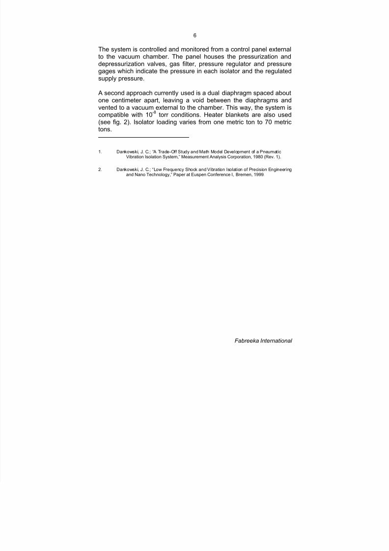
The system is controlled and monitored from a control panel externalto the vacuum chamber. The panel houses the pressurization anddepressurization valves, gas filter, pressure regulator and pressuregages which indicate the pressure in each isolator and the regulatedsupply pressure.
A second approach currently used is a dual diaphragm spaced aboutone centimeter apart, leaving a void between the diaphragms andvented to a vacuum external to the chamber. This way, the system iscompatible with 10
-8 torr conditions. Heater blankets are also used
(see fig. 2). Isolator loading varies from one metric ton to 70 metrictons.
1. Dankowski, J. C.; “A Trade-Off Study and Math Model Development of a PneumaticVibration Isolation System,” Measurement Analysis Corporation, 1980 (Rev. 1).
2. Dankowski, J. C.; “Low Frequency Shock and Vibration Isolation of Precision Engineeringand Nano Technology,” Paper at Euspen Conference I, Bremen, 1999.