-H ry-5 111 H I ENH E 11 · -H ry-5 111 H I E"NH E 11 . Created Date: 8/7/2016 1:02:55 PM
VACUCELL_S_en_np_mmm 0211 V 1.04_Blue Line
Vacuum cabinetsline Standard
VACUCELL 22, 55, 111Operating instructions
MMM Medcenter Einrichtungen GmbH Producer:
MMM MedcenterEinrichtungen GmbHSchulstrasse 29D – 82 166 Gräfelfing
Tel.: +49 89 89 92 26 20Fax: +49 89 89 92 26 30
Operating instructions VACUCELL-line Standard Page 1
VACUCELL_S_en_np_mmm 0211 V 1.04_Blue Line
Contents6.11.2002
1 GENERALLY.................................................................................................................................. 31.1 PURPOSE ..................................................................................................................................... 31.2 USE ............................................................................................................................................. 3
2 IMPORTANT INSTRUCTIONS ...................................................................................................... 32.1 UNPACKING, CHECKING, TRANSPORT AND HANDLING ...................................................................... 32.2 BEFORE PUTTING INTO OPERATION ................................................................................................ 42.3 USEFUL SPACE ............................................................................................................................. 5
3 DESCRIPTION OF THE UNIT ....................................................................................................... 63.1 GENERAL VIEW ............................................................................................................................. 63.2 CONTROL PANEL IN THE DOOR OF THE BOX .................................................................................... 73.3 CONTROL PANEL IN THE SUPERSTRUCTURE.................................................................................... 83.3 MAINS CONNECTION AND CONNECTORS ......................................................................................... 8
4 FUNCTION AND OPERATION...................................................................................................... 94.1 SWITCHING ON ............................................................................................................................. 94.2 SWITCHING OFF .......................................................................................................................... 104.3 SETTING-UP REQUIRED VALUES OF TEMPERATURE, TIME-DELAYED SWITCHING-OFF, NUMBER OFCYCLES, TIME-DELAYED SWITCHING-ON. ............................................................................................... 104.4 USER'S SUPPORTING FUNCTIONS................................................................................................. 124.5 LIST OF THE ERROR MESSAGES ................................................................................................... 124.6 PROTOCOL PRINTING .................................................................................................................. 124.7 SAFETY THERMOSTAT FUNCTION AND SETTING ............................................................................. 134.8 CREATION OF VACUUM IN THE CHAMBER ...................................................................................... 144.9 SEALING EXCHANGE AND DOOR SETTING..................................................................................... 14
5 SPECIFICATIONS OF THE UNIT................................................................................................ 155.1 ELECTRIC CONNECTION............................................................................................................... 16
6 CLEANING ................................................................................................................................... 16
7 MAINTENANCE ........................................................................................................................... 16
8 WARRANTY CONDITIONS AND SERVICE ............................................................................... 16
9 TRANSPORT AND STORAGE.................................................................................................... 17
10 METHOD OF LIQUIDATION OF THE PACKING AND OF THE DISCARDED UNIT................. 17
11 OPTIONS...................................................................................................................................... 1711.1 COMMUNICATION SW WARMCOMM FOR PC UNDER WINDOWS................................................. 1711.2 BOX „VACUSTATION“ .............................................................................................................. 1811.3 CHEMICALLY RESISTANT VACUUM PUMP................................................................................... 1811.4 SEPARATOR AND EMISSION CONDENSER.................................................................................. 1811.5 SYSTEM OF VACUUM CONTROL................................................................................................ 18
Operating instructions VACUCELL-line Standard Page 2
V 1.04_Blue Line VACUCELL_S_en_np_mmm 0211
Operating instructions VACUCELL-line Standard Page 3
VACUCELL_S_en_np_mmm 0211 V 1.04_Blue Line
1 Generally
1.1 Purpose
VACUCELL is an electrically heated and evacuated chamber which may be used afterevacuation to heat the objects located in it. Evacuated objects are placed on the shelves inthe chamber.The unit operates up to the temperature of 200 °C. The temperature course is controlled bymodern microprocessor (Fuzzy-logic) with digital display and Pt 100 temperature sensor.This system secures high precision of the temperature regulation and reliability of thetempering process. The unit is designed in accordance with appropriate standards ČSN EN- see 2.2, 5.1 and fulfils requirements of directions EU 89/336/EHS, 73/23/EHS (resp.93/42/EHS). Made of high-quality materials and using the latest technology. Each piecegoes through a careful output checking.
1.2 UseVACUCELL is designed to perform:- vacuum drying of easy oxidable matters with possible displacement of oxygen by inert gas- accelerated drying of form-simple and complicated parts- drying of samples up to constant weight at adjustable temperature and selectable timemode.
The unit may be used primarily in the following branches:- biology- cosmetics- pharmaceutics- food industry- chemistry- electric technology- plastics processing- engineeringThe unit is designed to be used and handled by the persons familiar with dealing with thelaboratory equipment and apparatuses.
2 Important instructions
2.1 Unpacking, checking, transport and handlingAfter unpacking please check that the unit and the accessories are complete andundamaged ). Possible damage must be immediately reported to the transporter. Whenhandling - lifting the box, etc - the box must not be lifted using the hand rail or the door! Liftthe box using the four hooks that you push into the openings in the side of longitudinal legsof the box.Standard delivery consists of the cabinet and two shelves.(order No.: V459046 - volume 22, V 459047 – volume 55, V 459048 – volume 111),silicon hose 8 x 18 for connection chamber/ vacuum source (order No. 0662132 ).

Operating instructions VACUCELL-line Standard Page 4
V 1.04_Blue Line VACUCELL_S_en_np_mmm 0211
2.2 Before putting into operation• Before beginning the work with the unit please read the operating instructions
carefully!
• The unit is designed to work in interior spaces within the ambient temperatures of5 °C up to 40 °C, at maximum relative humidity of 80 %.
• Install the instrument by plugging the power cord to a line voltage socket. Prescribedparameters of the supplies are stated in chapter Electric Connection.
♦ In case of temperatures above 100 °C a yellowed stain of the inner chamber wallscan occur. This stain is neither the material nor the unit’s defect..
♦ After the first switching-on the heating bodies start to be burnt, which results in acharacteristic smell; this smell disappears after several operating cycles.
• Minimum distance of the unit from the rear and side walls is 100 mm. Do not placeinflammable or explosive matters into the unit!
• Ovens are designed to be operated indoor within ambient temperatures from 5 °C to40 °C and at maximum relative humidity 80 %.
• Carrying capacity of the floor during installation of the device must correspond to theweight of the unit itself taking the weight of the maximum charge into consideration (seechapter Parameters of the unit).
• Goods are only to be put on trays into ovens, never directly on the bottom of theoven !
• No inflammable, explosive or toxic materials may be put into ovens! The sameapplies to materials that could give off such a stuff.
• The unit is not designed for warming of liquids and does not contain any liquids.
• In case of any manipulation with the unit, other than its normal use, disconnect itfrom electric mains by pulling the supply cord from the socket ! When depressing the key
the unit is set only in the stand-by mode, but it is not disconnected from electricmains !
• In case the unit is not in use for a longer time period, disconnect it from the mainsby the mains switch (position 2 - panel of the upper piece) or by pulling the supply cordfrom the socket.
• Protection of the thermal box, its surrounding and of the treated material againstinadmissible temperature rise is secured by the protection thermostat The class ofprotection of the unit is 2 according to the EN 61010-2-010. Check regularly – daily – thefunction of protection thermostat
Operating instructions VACUCELL-line Standard Page 5
VACUCELL_S_en_np_mmm 0211 V 1.04_Blue Line
• The unit must not be placed on a pad that could cause a danger of fire orsmothering in case of falling some hot object out of the cabinet.
• Maximum permissible load: see chapter Specifications of the unit.
• Do not put any object on the outer surfaces of the ovens.
• During the operation of the ovens at high temperatures the maximal permittedtemperature of 70 °C can be surpassed on their outer surface (neighbourhood of thechamber sealing, glass door), where a danger of burn can occur. Please pay the highestattention.
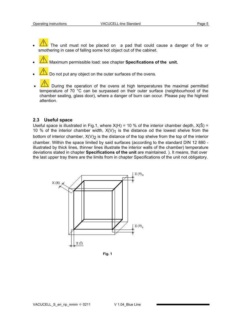
2.3 Useful spaceUseful space is illustrated in Fig.1, where X(H) = 10 % of the interior chamber depth, X(Š) =10 % of the interior chamber width, X(V)1 is the distance od the lowest shelve from thebottom of interior chamber, X(V)2 is the distance of the top shelve from the top of the interiorchamber. Within the space limited by said surfaces (according to the standard DIN 12 880 -illustrated by thick lines, thinner lines illustrate the interior walls of the chamber) temperaturedeviations stated in chapter Specifications of the unit are maintained. ). It means, that overthe last upper tray there are the limits from in chapter Specifications of the unit not obligatory.
Fig. 1

Operating instructions VACUCELL-line Standard Page 6
V 1.04_Blue Line VACUCELL_S_en_np_mmm 0211
3 Description of the unit
3.1 General view
Fig. 2
1 Panel of the regulator 8 Power supply cord2 Control panel 9 built-in socket for the vacuum pump3 Control panel cover 10 vacuum fittings4 Panel of the superstructure 11 inlet to connect the vacuum pump5 Pt 100 temperature sensor
and12 heat resisting glass of the door
Safety thermostatsensor 13 measuring feedthrough6 Heating bodies 14 RS-232C connector7 Power part 15 supply of inert gas to the needle valve
16 ball valve
Operating instructions VACUCELL-line Standard Page 7
VACUCELL_S_en_np_mmm 0211 V 1.04_Blue Line
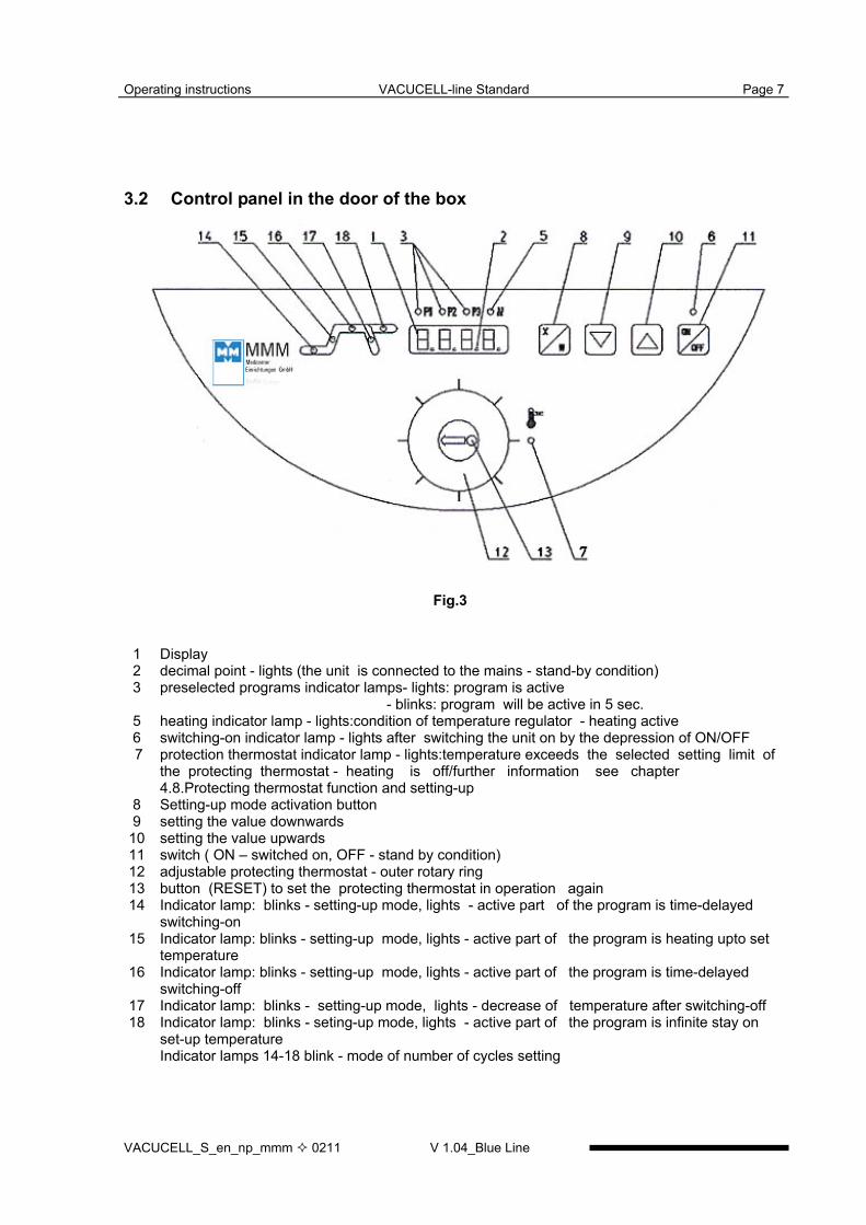
3.2 Control panel in the door of the box
Fig.3
1 Display2 decimal point - lights (the unit is connected to the mains - stand-by condition)3 preselected programs indicator lamps- lights: program is active
- blinks: program will be active in 5 sec.5 heating indicator lamp - lights:condition of temperature regulator - heating active6 switching-on indicator lamp - lights after switching the unit on by the depression of ON/OFF 7 protection thermostat indicator lamp - lights:temperature exceeds the selected setting limit of
the protecting thermostat - heating is off/further information see chapter4.8.Protecting thermostat function and setting-up
8 Setting-up mode activation button9 setting the value downwards
10 setting the value upwards11 switch ( ON – switched on, OFF - stand by condition)12 adjustable protecting thermostat - outer rotary ring13 button (RESET) to set the protecting thermostat in operation again14 Indicator lamp: blinks - setting-up mode, lights - active part of the program is time-delayed
switching-on15 Indicator lamp: blinks - setting-up mode, lights - active part of the program is heating upto set
temperature16 Indicator lamp: blinks - setting-up mode, lights - active part of the program is time-delayed
switching-off17 Indicator lamp: blinks - setting-up mode, lights - decrease of temperature after switching-off18 Indicator lamp: blinks - seting-up mode, lights - active part of the program is infinite stay on
set-up temperatureIndicator lamps 14-18 blink - mode of number of cycles setting
Operating instructions VACUCELL-line Standard Page 8
V 1.04_Blue Line VACUCELL_S_en_np_mmm 0211
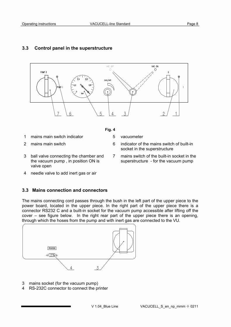
3.3 Control panel in the superstructure
Fig. 4
3.3 Mains connection and connectors
The mains connecting cord passes through the bush in the left part of the upper piece to thepower board, located in the upper piece. In the right part of the upper piece there is aconnector RS232 C and a built-in socket for the vacuum pump accessible after lifting off thecover – see figure below. In the right rear part of the upper piece there is an opening,through which the hoses from the pump and with inert gas are connected to the VU.
3 mains socket (for the vacuum pump)4 RS-232C connector to connect the printer
1 mains main switch indicator 5 vacuometer2 mains main switch 6 indicator of the mains switch of built-in
socket in the superstructure3 ball valve connecting the chamber and
the vacuum pump , in position ON isvalve open
7 mains switch of the built-in socket in thesuperstructure - for the vacuum pump
4 needle valve to add inert gas or air
Operating instructions VACUCELL-line Standard Page 9
VACUCELL_S_en_np_mmm 0211 V 1.04_Blue Line
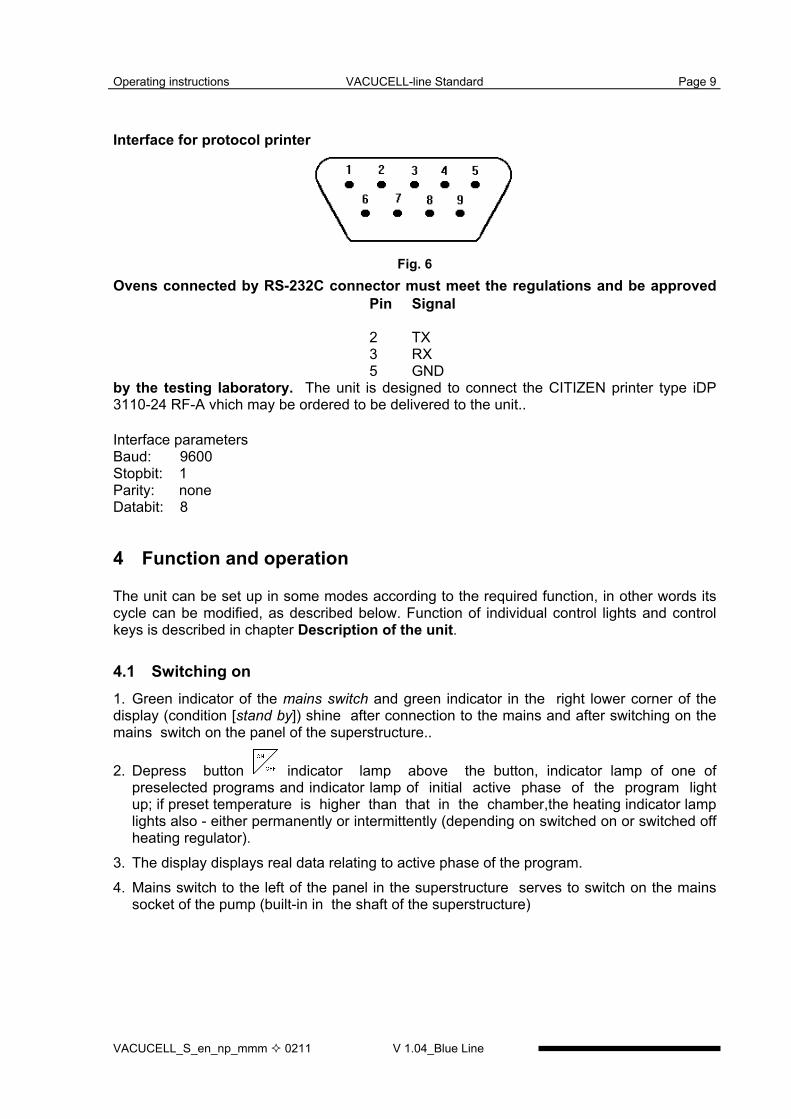
Interface for protocol printer
Ovens connected by RS-232C connector must meet the regulations and be approved
by the testing laboratory. The unit is designed to connect the CITIZEN printer type iDP3110-24 RF-A vhich may be ordered to be delivered to the unit..
Interface parametersBaud: 9600Stopbit: 1Parity: noneDatabit: 8
4 Function and operation
The unit can be set up in some modes according to the required function, in other words itscycle can be modified, as described below. Function of individual control lights and controlkeys is described in chapter Description of the unit.
4.1 Switching on1. Green indicator of the mains switch and green indicator in the right lower corner of thedisplay (condition [stand by]) shine after connection to the mains and after switching on themains switch on the panel of the superstructure..
2. Depress button indicator lamp above the button, indicator lamp of one ofpreselected programs and indicator lamp of initial active phase of the program lightup; if preset temperature is higher than that in the chamber,the heating indicator lamplights also - either permanently or intermittently (depending on switched on or switched offheating regulator).
3. The display displays real data relating to active phase of the program.4. Mains switch to the left of the panel in the superstructure serves to switch on the mains
socket of the pump (built-in in the shaft of the superstructure)
Fig. 6
Pin Signal
2 TX3 RX5 GND

Operating instructions VACUCELL-line Standard Page 10
V 1.04_Blue Line VACUCELL_S_en_np_mmm 0211
4.2 Switching off
Press the key . The display turns off, only the green control light in the lower right corneris on (stand by). Disconnection from the mains is performed by switching off the mainsswitch, in case of longer setting out of operation or during the repair by pulling the plug of themains cable from the socket. The total unplugging from mains (in case of a long-term puttingout of operation or a maintenance) is achieved by pulling the service cord from a socket –see also chapter Pre-installation.
4.3 Setting-up required values of temperature, time-delayed switching-off,number of cycles, time-delayed switching-on.
1. Set preselection of program 1 or 2 or 3 by means of or . After depressing
or the control lamp of further program starts to flicker. This program will be activated
within ca. 5 sec, if no other button is depressed during this time. Setting by means of
or will cause the stop of the running cycle and starting a new cycle with the pre-selected parameters.
Setting-up cycle begins with setting required temperature,
2. Depress , indicator lamps 15, 16 (Fig.3) begin to flicker, by means of setrequired temperature in °C on the display
The lowest adjustable and displayable temperature interval is 1 °C. Indicator lamps of the segments flicker permanently.
3. By depressing change to the segment of setting the time-delayed switching-
off, by means of set required value in hours and minutes from 0 (symbol---)to 99 hrs 59 min on the display, indicator lamps 16, 17 (Fig.4) flicker.
4. By depressing change to the segment of setting the number of cycles and by
means of set the number of cycles from 1 up to 255 (more information onthe cycles see 4.4) - all indicator lamps flicker during setting up.
This function can be used with time-delayed switching-off ≠ 0 only. Set the possibility to select the cycles by means of the user'supporting function.
5. By depressing change to the segment of setting the time-delayed switching-
on and by means of set the required value in minutes from 0 up to 99 hrs 59min, indicator lamp 14 (Fig.3) flickers.
6. Start the program by double depressing (start of the program is announced by an acoustic signal), data on real temperature with time count-down flickers on the display during the phase of time-delayed switching on. The heating is switched on after
reaching the time of zero and the display shows the real temperature in the chamber. After reaching the required temperature

Operating instructions VACUCELL-line Standard Page 11
VACUCELL_S_en_np_mmm 0211 V 1.04_Blue Line
a) in case of setting the time-delayed switching-off, the chamber temperature with the settime count-down begins to flicker on the display
b) or in case of unlimited switching-off, the chamber temperature with the rising time flickeron the display.Permanently lighting indicator lamps give information on just active program segment.
7.Individual set values can be checked during the run of the program - by depressing
the required value is shown on the display, indicator lamps flicker, by another
depressing within 5 seconds you change to the next segment, in this way allsettings can be checked successively.
Original program continues if you use no control element within 5 seconds.
8. Similarly, during the course of the program, you can change the already set values,when
a) after setting the last value - time-delayed switching-on - you wait approximately 5seconds, the program continues with changed values from the point of interruption
b)after setting the value you start the program by double depressing , the programstarts with new values from the beginning.
9. Total course of one cycle is illustrated in Fig.7.
Fig. 7
Phase function0 time-delayed switching-ona temperature riseb time-delayed switching-offc temperature drop after switching-off
Operating instructions VACUCELL-line Standard Page 12
V 1.04_Blue Line VACUCELL_S_en_np_mmm 0211
4.4 User's supporting functions
Entry the function by simultaneous depressing +
By means of set on the displaya) U1 - setting the period of print of the printer from 0 up to 255 min, enter the setting by
means of b) U2 - ON or OFF - permission or prohibition of cycles (for all pre-selections at the same
time), enter the setting by depressing ; a cycle means multiple repetition of theprogram with set time-delayed switching-off and switching-on.
Leave the setting by depressing and leave the function by depressing .c) U3 – Prn or PC – data transfer via interface RS 232 either on the printer (Prn) or, in caseof using the program DS Com, on the computer (PC); set Prn or PC by means of
4.5 List of the error messages
Err 1 - not calibrated (the service engineer performs compensation of measuring conduitsof the sensor).
Err 2 - freeErr 3 - freeErr 4 - Err 10 - HW error (report this event to the producer)
4.6 Protocol printingPrinting the protocol with the help of CITIZEN printer, type iDP 3110-24 RF-A.By setting the interval of the printer you determine the time intervals in which the actual valueof the temperature in the chamber will be printed. Magnitude of this interval is stated in theheading of the excerpt. Interval of the printer can be set on the display within: tmin = 1minute, tmax = 255 minutes ( 4 hours 15 minutes) by 1 minute.1. We start from the condition, when the display displays real value of the temperature.
Connect the printer to the hot air box by means of the cable with serial connector (RS-232C) into the socket for the printer (see Fig.4), the other end of the cable connect to theconnector in the rear part of the printer. Connect the printer to the mains by connectingthe connector of the adapter AC 230 V, 50 Hz, 0.1 A/DC 7 V,1.6 A into the socket in therear part of the printer and by pushing the adapter into the mains socket. Switch on theswitch on the right side of the printer. Indicator POWER and SEL start shining. Theprinter is in the ON-LINE mode and it prints in this mode only! If you want to feedthe paper, depress the key LF. This may be performed only in the OFF-LINEmode, i.e. after depressing the key SEL, when the indicator SEL stops shining.Re-depress the SEL key to restore the ON-LINE mode, indicator
2. According to par. Setting-up required values of temperature set the required intervalupwards or downwards

Operating instructions VACUCELL-line Standard Page 13
VACUCELL_S_en_np_mmm 0211 V 1.04_Blue Line
3. The printer prints the head containing the type of the unit, set temperature and selectedtime interval. Values of the following data are printed in one line under this heading:
time from starting the program and actual temperature in the chamber.4. Switching the print off is performed by setting the print interval to 0 (symbol ---).5. In case of change of set operation conditions of the oven or in case of change of print
interval a new heading will be printed (this is not valid when set interval is 0 (symbol---)).6. If the power supplying the apparatus fails , after the power recovery the printer prints the
sign Power recovery! and the actual temperature value. Time intervals start counting
immediately after power recovery. After switching-off and switching-on by means of again a new head is printed.
7. If the power supplying the printer fails or the printer is turned off, no message is printedafter turning the printer on again or after power recovery .
8. Setting of the DIP / switches of the printer: all four pins are in lower position OFF.
4.7 Safety thermostat function and setting
Safety thermostat serves to protect the thermal box, its surrounding and treated materialagainst inadmissible exceeding the set temperature (e.g. it prevents damage or destroying ofmaterial samples in case of a damage to the temperature regulator or unintentional setting ofhigher temperature in the chamber of the unit than respective sample is able to bear).
In case of correct setting, the safety thermostatswitches off at approximately by 5 °C up to10 °C, higher temperature than the temperature set on the regulator of the unit. Setting thethermostat:1. Press the external rotary ring of the thermostat towards the control panel and with
simultaneous slight pressure turn it to the right (clockwise) up to the limit position(maximum). The center with the knob turn together with the external ring.
2. Thermal box is heated up to required operation temperature and left to stabilize forapproximately 10 minutes at this temperature.
3. Then turn the ring slightly to the right and depress the key of the thermostat. A slight clickis heard and indicator safety thermostat stops shining. If the click is not to be heard andthe indicator does not stop shining turn the ring slightly more to the right and depress thekey again. Repeat this procedure as long as the indictor stops shining. Only in such caseis the thermostat set onto required temperature. If the unit is set to maximum temperatureturn the ring to the right to maximum according to item
4. Operation of the unit continues..
NOTICE:Used safety thermostatis of class 2 (according to EN 61010-2-010) - mark TWB. Whensurpassing set temperature in the chamber, the thermostat switches the heating bodies offand the indicatorsafety thermostat starts shining (the unit does not heat even if the indicatorheating shines). Even after the drop of the temperature below set limit of the protectionthermostat, heating remains switched off. It is necessary to depress the knob of the safetythermostatto restore the operation. Indicatorsafety thermostat stops shining.

Operating instructions VACUCELL-line Standard Page 14
V 1.04_Blue Line VACUCELL_S_en_np_mmm 0211
4.8 Creation of vacuum in the chamber
Push the hose from the vacuum pump onto the end of the vacuum piping of the unit (Fig.2,position 11) which is accessible through the side cut-out in the superstructure. Connect themains cord of the vacuum pump into the socket in the shaft of the superstructure and switchthe pump on. Set the ball valve on the front panel of the superstructure into the position VACON. Value of vacuum begins to rise on the vacuometer in the front panel after several tens ofseconds (the needle valve and the door must be properly closed).
4.9 Sealing exchange and door settingTake the whole sealing off, begin in the middle bottom part.Fix the new sealing on the edge of the chamber, begin in the middle bottom part. Slam thesealing between the chamber and the outer cover.To check up the tighteness place a sheet of paper between the door and the chamber whenclosing the door. Pull it out slowly, you should feel a stronger resistance.The door is adjustable at four points (see Fig.12):Pins of the lock – on the left front part of the jacket – at the top and at the bottom: these pinscan be loosened by means of the lock nut and they can be adjusted forwards/backwards bymeans of the thread.Door hinge, lower: by loosening the screw M8 at the front on the right side of the foot it ispossible to adjust the door forwards/backwards in the horizontal direction.Door hinge, upper 2: after removing the cover of the extension part the screws M8 in thefront right corner become accessible. After loosening these screws the position of the doorcan be adjusted.Adjust the door so that when closed the rubber sealing of the chamber would fit to the sheetof the floating door along the whole perimeter. To check it up place a sheet of paper betweenthe sealing and the metal sheet of the floating door before it is closed, it is possible to takethe paper out against a small resistance.
Operating instructions VACUCELL-line Standard Page 15
VACUCELL_S_en_np_mmm 0211 V 1.04_Blue Line
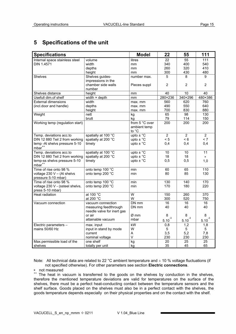
5 Specifications of the unit
Specifications Model 22 55 111Internal space stainless steelDIN 1.4571
volumewidthdepthsheight
litresmmmmmm
22340260300
55400320430
111540410480
Shelves Shelves guides-impressions in thechamber side wallsnumber
number max.
Pieces suppl
5
2
8
2
9
2
Shelves distance height mm 40 10 40Usefull dim.of shelf width × depth mm 280×236 340×296 480×386External dimensions(incl.door and handle)
widthdepthsheight
max. mmmax. mmmax. mm
560490700
620550830
760640880
Weight nettbrutt
kgkg
6579
98114
130150
Working temp (regulation start) from 5 °C overambient tempto °C
200 200 200
Temp. deviations acc.toDIN 12 880 Teil 2 from workingtemp -Al shelvs pressure 5-10mbar++
spatially at 100 °Cspatially at 200 °Ctimely
upto ± °Cupto ± °Cupto ± °C
2< 50,4
2< 60,4
2< 70,4
Temp. deviations acc.toDIN 12 880 Teil 2 from workingtemp-ss shelvs pressure 5-10mbar++
spatially at 100 °Cspatially at 200 °Ctimely
upto ± °Cupto ± °Cupto ± °C
10180,5
10180,5
11∗
1,0
Time of rise onto 98 %voltage 230 V – (Al shelvspressure 5-10 mbar)
onto temp 100 °Conto temp 200 °C
minmin
6080
6585
110130
Time of rise onto 98 %voltage 230 V - (ssteel shelvs,press 5-10 mbar)
onto temp 100 °Conto temp 200 °C
minmin
130170
140180
170220
Heat radiation at 100 °Cat 200 °C
WW
150300
260520
370750
Vacuum connection vacuum connectionmeasuring feedthroughneedle valve for inert gasor airattainable vacuum
DN mmDN mm
Ø mmmbar
1640
85.10
-3
1640
85.10
-3
1640
85.10
-3
Electric parameters –mains 50/60 Hz
max. inputinput in stand by modecurrentnominal voltage
kWWAV
0,85
3,5230
1,25
5,2230
1,85
7,8230
Max.permissible load of theshelves
one shelftotally per unit
kgkg
2035
2545
2565
Note: All technical data are related to 22 °C ambient temperature and ± 10 % voltage fluctuations (ifnot specified otherwise). For other parameters see section Electric connections.
∗ not measured++ The heat in vacuum is transferred to the goods on the shelves by conduction in the shelves,therefore the mentioned temperature deviations are valid for temperatures on the surface of theshelves, there must be a perfect heat-conducting contact between the temperature sensors and theshelf surface. Goods placed on the shelves must also be in a perfect contact with the shelves, thegoods temperature depends especially on their physical properties and on the contact with the shelf.
Operating instructions VACUCELL-line Standard Page 16
V 1.04_Blue Line VACUCELL_S_en_np_mmm 0211
5.1 Electric connection
voltage system TNC or TNSclass of protection against dangerous touch Iexternal circuits insulation double insulation (tested by 4 kV voltage)type of plug of the unit CEE-7/VII, IEC-83/CH, 16 A/250 Vsocket protection min. 10 Aprotection according to EN 60529 IP 20overvoltage category according to IEC 664(EN 61010) II in case of pollution degree 2used fuses 2xF10 A,1xT400mA (î 5x20 mm)plug CEE-7/VII, IEC-83/CH, 16 A/250 V (event. some other according to the customer’swish)Recommended cable leading from the switchboard to the socket 3 × 2,5 mm2 Cu.With one-phase units the cable is 3 × 2,5 mm2 Cu. The type of the socket corresponds to thetype of the plug.
6 Cleaning
Cleaning is to be performed only after cooling the unit down and after disconnection of themains cord from the mains. Internal walls of the chamber and the surface of the unit is to becleaned with water and detergent or suitable chemical means, it is necessary to use rags thatare not rough and do not release fibres. Abrasive cleaning means are not recommended,they could couse scratching of the metal sheets.In case of contamination of the oven either outside or inside by dangerous material the useris responsible to carry out a proper decontamination of all contaminated surfaces with asuitable and approved disinfecting agent.Before using of any method of cleaning or decontamination different from ourrecommendations we recommend to verify at the producer the compatibility of the procedure.
7 Maintenance
The unit requires no special maintenance. In case of troubles, please, contact the service.
8 Warranty conditions and service
MMM guarantees faultless delivery and function within the frame of contract rules andwarranty time. Fixed sale and delivery conditions of MMM are valid.MMM assumes no responsibility for the faults or other losses originated due to normal wear,chemical of physical influences, natural disasters, extreme loading, incorrect operation orimproper or inadequate use, especialy when not observing the appended operatinginstructions, in case of incorrect installation, in case of damages originated due to the effectof foreign bodies, as well as in case of faulty or improper maintenance or repair. In the caseof sending back to the producer (to repair or exchange at claim), use the original package. Inthe other case you accept the responsibility for eventuel damage during transport and theproducer will exact from you a compensation of necessary coherent repairs.
Operating instructions VACUCELL-line Standard Page 17
VACUCELL_S_en_np_mmm 0211 V 1.04_Blue Line
For a correct connection to the mains observe the technical data and Operatinginstructions.
Important notice:MMM (producer) is responsible for safety and technical properties of the unit only in case,when the repairs and modifications of the unit are performed by herself or by the organizationspecifically authorized by her, and when the parts will be during the repair substituted by thespare parts admitted by the producer and spare parts satisfying the quality standard of MMM.
MMM recommends the user of the unit to ask the one who carried out the repair for thecertificate on the kind and extent of work, if need be with the data concerning the change ofnominal data or work extent, date of performance, name of the company and signature.
9 Transport and storage
The unit is being prepared for transport by an authorized person (who dismounts theconnections). The unit shall be transported in its original package. If you send the deviceback (for instance to repair or in case of reclamation), use the original package. Otherwiseyou take responsibility for possible damaging during the transport and producer will claimthe costs for appropriate repairing of you. The device shall be stored in the range oftemperatures from 0 °C to 40 °C.
10 Method of liquidation of the packing and of the discarded unit
a) pallet – liquidation in the refuse incinerating plantb) cardboard - recyclable wastea) discarded unit - liquidation to be done by a company authorized to handle the waste, the
unit contains no poisons.
11 Options
11.1 Communication SW DS Com for PC under Windows
The software DS Com is designed to record the temperature course in the thermal cabinets.Data obtained during the regulation are displayed in form of a graph (with time on thehorizontal axis and obtained data on the vertical axis). The software enables to follow theregulation in real time, to store the regulation course to a file on the disc and to view thealready stored files.Operation instructions of this software are delivered together with the installation software,minimal requirements on PC hardware for the program DS Com 2.1 are:• IBM-compatible PC (386 and above)• Operation system Windows 95 and above• 80 MB RAM• one-hour-record of data requires free space of about 60 KB on the hard disc• free serial port

Operating instructions VACUCELL-line Standard Page 18
V 1.04_Blue Line VACUCELL_S_en_np_mmm 0211
11.2 Box „Vacustation“Serves for placing the vacuum pump MZ2C, resp. MD4C (event. another vacuum pump withappropriate dimensions) in the space of the box, the vacuum box Vacucell is placed on top ofit. Both elements are screwed together.
11.3 Chemically resistant vacuum pumpFor instance membrane vacuum pumps MZ2C (suction power cca 1.7 m3/h, achievablevacuum cca 9 mbar) and MD4C (suction power cca 3 m3/h, achievable vacuum cca 2 mbar)are recommended.
11.4 Separator and emission condenserThe separator of the gas/steam exhausted from the chamber is placed between the chamberand the pump (the separating has a favourable influence on the power of the vacuum pump),emission condenser with water cooler is placed on the pump outlet and reduces the amountof emissions of the exhausted gas/steam in the outer space. Both parts are made of glassand are fixed on the pump.
11.5 System of vacuum controlConsists of the part CVC II and an electromagnetic suction valve. It enables to keep theconstant value of vacuum in the chamber and to show the measured values on the displayCVC II. CVC II is placed separately outside the box Vacucell and the suction valve isinstalled in the extension part of Vacucell.