Vacon NXP HXT070 Cooling Unit Installation Manual
61
Commissioning and Maintenance Manual HXT070 cooling unit, SS-Piping / PVC-C Piping Version 1.0
-
Upload
tanutiganu -
Category
Documents
-
view
61 -
download
1
description
v
Transcript of Vacon NXP HXT070 Cooling Unit Installation Manual

Commissioning and Maintenance ManualHXT070 cooling unit, SS-Piping / PVC-C Piping
Version 1.0


VACON • 3
24-hour support +358 (0)40 837 1150 • Email: [email protected]
QUICK START-UP GUIDE
THE FOLLOWING STEPS OF THE QUICK START-UP GUIDE MUST BE PERFORMED DURING THEINSTALLATION AND COMMISSIONING.
If any problems occur, contact your local distributor.
1. Check that delivery corresponds to your order.
2. Before starting commissioning, read carefully the safety instructions in Chapter 1 SAFETY.
3. Check that the specified installation location and ambient conditions comply with thespecifications. Refer to Chapter 2.3.2, Required ambient conditions.
4. Any customer made piping must be thoroughly flushed before connecting to the HX-unit.
5. Check that the liquid quality is approved. Refer to Chapter 2.3.1, Liquid quality.
6. Connect the mechanical and electrical couplings. Refer to Chapter 3.1.2, Pipe connectionsand 3.2 STEP 2, ELECTRICAL PART.
7. Adjust the HX control unit parameters to match the specific project requirements. Refer toChapter 3.3.2, Application parameter list.
8. Perform a pressure test to the primary circuit and secondary circuit connections. Refer toChapter 3.1.4, Pressure test.
9. Add coolant to the circuits and de-air them according to the instructions in 3.1.6, Addingliquid and de-airing.
10. Adjust the primary circuit flow and temperature to match the project requirements. Refer toChapter 3.4.2, Adjusting the system flow and setting the switch point of the FTSA11.
11. Do not energize the main drives before the HX-unit has been running for 30 min without anyalarms. Refer to Chapter 3.4.3, Checklist before starting main NX drives.
Vacon Plc is not responsible for the use of its products contrary to these instructions.

4 • VACON
Tel. +358 (0)201 2121 • Fax +358 (0)201 212 205
ABOUT THE VACON HX-UNIT MANUAL
The Commissioning and Maintenance Manual provides you with the necessary information about themaintenance and commissioning of a Vacon HX-unit. We recommend that you carefully study theseinstructions before powering up a Vacon liquid-cooled drive and HX-unit for the first time.
This manual is available both in paper and electronic editions. We recommend you use the electronicversion if possible. If you use the electronic version, you benefit from the following features:
The manual contains several links and cross-references, which make it easier for the readerto move around in the manual, to check and find things faster.
The manual contains hyperlinks to web pages. To visit these web pages through the links,you must have access to the Internet and have an Internet browser installed in yourcomputer.

VACON • 5
24-hour support +358 (0)40 837 1150 • Email: [email protected]
VOCABULARY
Primary circuit,HXT070-PS01
A closed circuit filled with coolant that connects the drive to the HX-unit.
Secondary circuit,HXT070-P002
A circuit filled with coolant that connects the HX-unit to thecustomer piping.
HX-unit HXT070 cooling unit (see the front picture of the manual). Theordering code for the unit on the front page is HXT-M-070-N-P/S, butit is referred to as HXT070 or just plain HX-unit for short.
Drive Liquid cooled frequency converters or inverters that are connectedto the HX-unit.
Main drive A term used in some contexts for the Vacon NX liquid Cooledconverters so that they are more easily separated from the air-cooled Vacon NXP 0009 used in the HX-unit. The main drive conceptmight also include other liquid cooled electrical equipment.
HX control unit The air-cooled NXP 0009 drive that is placed inside the HX-unit forthe purpose of controlling and monitoring the primary circuit pumpand instruments.

6 • VACON
Tel. +358 (0)201 2121 • Fax +358 (0)201 212 205
INDEX
1. SAFETY .......................................................................................................................... 8
1.1 USE OF SYMBOLS .......................................................................................................................... 81.2 GENERAL WARNINGS AND NOTES WHEN WORKING WITH THE HX-UNIT ............................. 9
2. INTRODUCTION ............................................................................................................ 10
2.1 ABOUT THIS MANUAL ................................................................................................................. 102.2 PROCESS AND INSTRUMENTATION .......................................................................................... 11
2.2.1 Primary circuit components and function ..................................................................... 122.2.2 Secondary circuit components and function ................................................................. 122.2.3 Control unit ...................................................................................................................... 132.2.4 Instruments and their function ...................................................................................... 132.2.5 Control / supervision parameters.................................................................................. 142.2.6 HX-unit electrical box ..................................................................................................... 15
2.3 INSTALLATION SPECIFICATIONS .............................................................................................. 162.3.1 Liquid quality ................................................................................................................... 162.3.2 Required ambient conditions ......................................................................................... 17
3. COMMISSIONING .......................................................................................................... 18
3.1 STEP 1, MECHANICAL PART ...................................................................................................... 183.1.1 General installation instructions ................................................................................... 183.1.2 Pipe connections ............................................................................................................. 183.1.3 Pipe flushing.................................................................................................................... 193.1.4 Pressure test ................................................................................................................... 203.1.5 Setting up the primary circuit ........................................................................................ 213.1.6 Adding liquid and de-airing ............................................................................................ 223.1.7 Adding corrosion inhibitor when using a fresh water system ..................................... 23
3.2 STEP 2, ELECTRICAL PART ........................................................................................................ 253.2.1 Power supply ................................................................................................................... 253.2.2 Signal cables ................................................................................................................... 25
3.3 STEP 3, CONTROL UNIT SETUP ................................................................................................. 263.3.1 Basic setup ...................................................................................................................... 263.3.2 Application parameter list .............................................................................................. 263.3.3 Parameter description.................................................................................................... 273.3.4 General information about alarms and shutoff limits .................................................. 293.3.5 FTSA11 flow switch function .......................................................................................... 293.3.6 Temperature set points .................................................................................................. 313.3.7 Temperature alarm settings .......................................................................................... 363.3.8 Low pressure alarm ....................................................................................................... 373.3.9 Leak switch alarm specifications .................................................................................. 373.3.10 Three-way valve actuator settings................................................................................. 38
3.4 STEP 4, ADJUSTING THE FLOW ................................................................................................. 393.4.1 Starting the pump ........................................................................................................... 393.4.2 Adjusting the system flow and setting the switch point of the FTSA11 ...................... 403.4.3 Checklist before starting main NX drives ..................................................................... 41
4. UNIT MAINTENANCE .................................................................................................... 42
4.1 GENERAL MAINTENANCE .......................................................................................................... 424.1.1 Renewing liquid in the primary circuit .......................................................................... 424.1.2 Maintenance schedule .................................................................................................... 42

VACON • 7
24-hour support +358 (0)40 837 1150 • Email: [email protected]
4.2 MAINTENANCE BY COMPONENT............................................................................................... 424.2.1 Pump ................................................................................................................................ 424.2.2 Heat exchanger ............................................................................................................... 444.2.3 Pressure vessel .............................................................................................................. 46
5. TROUBLESHOOTING ..................................................................................................... 47
5.1 Alarms and shutoffs .................................................................................................................... 475.1.1 Flow fault ......................................................................................................................... 475.1.2 Temperature alarms and shutoffs ................................................................................. 495.1.3 Low pressure alarm ....................................................................................................... 525.1.4 Leak alarms .................................................................................................................... 53
6. TECHNICAL SPECIFICATION ......................................................................................... 54

8 • VACON SAFETY
Tel. +358 (0)201 2121 • Fax +358 (0)201 212 205
1. SAFETY
This chapter contains the general safety instructions, which you must follow when installing,commissioning, operating and maintaining the HX-unit. Read the safety instructions before you startto work on the unit.
1.1 USE OF SYMBOLS
For your own safety, please pay special attention to the instructions marked with the followingsymbols:
Risk of death. Instructions on preventing a possible severehazard to persons or equipment.
Risk of damage. Instructions on preventing possible damageto equipment.
Hot surface. Instructions on preventing a possible minorhazard to persons or equipment.
NOTE
Notification

SAFETY VACON • 9
24-hour support +358 (0)40 837 1150 • Email: [email protected]
1.2 GENERAL WARNINGS AND NOTES WHEN WORKING WITH THE HX-UNIT
These safety instructions are intended for all who work on the HX-unit. These instructions includeonly a part of the complete safety instructions. Read the Vacon NX Liquid Cooled User’s Manualsafety instructions as well. Ignoring the instructions can cause physical injury or death. It can alsocause serious malfunctions to the HX-unit that is not covered by the warranty. When working on theHX-unit generally acknowledged safety standards, EU directives and national regulations must alsobe followed.
1 Only qualified and authorized electricians and mechanics are allowed tocarry out the installation and maintenance work on the HX-unit.
2 Do not open the drive section doors while the drives are online. If yoususpect a coolant leak in the drive section, shut down the drives anddisconnect the power to them before opening the drive section cubicledoors.
3 When working with the HX-unit together with the frequency converter, alsofollow the Vacon NX Liquid Cooled Drive User’s Manual safety instructions toprevent any accidents.
4 Any installation work on the HX-unit must be done with power off. The powermust not be reconnected before the installation work is complete.
5 The primary cooling circuit can contain hot coolant (over +50 C) duringnormal operation. Serious burns are possible. Before performingmaintenance, switch off the unit and allow it to cool down.
6 The primary cooling circuit can contain high-pressure coolant (6 bar) duringoperation. Release the pressure in the HX-unit before performingmaintenance. Use safety goggles.
7 The HX-unit must be positioned in a non-hazardous area where it can’t posea threat to any main systems or persons.
8 The coolant consists, depending on the project, of plain drinking water or ofa mix of water, propylene glycol and corrosion inhibitors. Glycol andcorrosion inhibitors are dangerous to health. If you get coolant mixed withglycol or corrosion inhibitors in your eyes, on your skin, or in your mouth,seek medical advice.
NOTE
1 It is the customer’s and/or end-user’s responsibility to provide flow andtemperature control to the secondary circuit. If the project specified flowand temperature for the secondary circuit is not met the warranty is notvalid.
2 Retain these operating instructions during the entire life cycle of the HX-unit.
3 The HX-unit should always be transported empty (that is, without coolant) toprevent damage caused by low and high ambient temperatures.
4 Do not allow any force or vibrations to enter the unit through the secondarycircuit pipe connections or through the fixing points of the HX-unit. This willshorten the MTBF (mean time between failure) of the HX-unit.
5 If the HX-unit is purchased without a cubicle, place it inside a cubicle ofchoice and fix the HX-unit frame to the cubicle frame.
6 Always install a filter before the HX-unit if the secondary circuit coolingliquid contains particles larger than 2 mm. If the secondary circuit liquidcontains chemical or biological residue the MTTM (Mean time toMaintenance) is significantly reduced due to clogging in the plate heatexchanger inside the HX-unit.

10 • VACON INTRODUCTION
Tel. +358 (0)201 2121 • Fax +358 (0)201 212 205
2. INTRODUCTION
2.1 ABOUT THIS MANUAL
This manual provides information on commissioning and maintenance issues of the HXT070 coolingunit. The manual is intended to be used by Vacon’s own personnel as well as the customer and/orend-user.
To follow the instructions in this manual, the reader must have a reasonable knowledge ofmechanics and electrics.
Only a qualified and authorized mechanic is allowed to perform commissioningor maintenance of the HX-unit. A qualified and authorized electrician shouldaccompany the mechanic performing maintenance or commissioning on theunit.
This manual is divided into following chapters:
Chapter 1 SAFETY explains the symbols used in this manual and contains the general safetyinstructions. Read the safety instructions before continuing.
Chapter 2 INTRODUCTION explains how the HX-unit is built by looking into the unit process andinstrumentation. The idea is to give the reader a basic understanding of the process and controlphilosophy. This chapter also includes specifications on correct ambient conditions for the HX-unit.
Chapter 3 COMMISSIONING provides information on how to install and how to start-up the unit.The chapter explains, among other things, how the unit is to be filled with liquid and how the systemis to be de-aired. The chapter also shows the user the correct valve positions for start-up and how toset up the HX control unit.
Chapter 4 UNIT SERVICE explains required maintenance and some repair instructions for thecomponents inside the cooling unit. More unit maintenance instructions can be found in thecomponent maintenance handbooks. They are found at the end of the HX-unit Commissioning andMaintenance folder that is supplied with the unit.
Chapter 5 TROUBLESHOOTING includes fault tracing to help the user identify and solve a problemwhen the HX control unit (air-cooled Vacon NXP 0009) has an active alarm or fault.
Chapter 6 TECHNICAL SPECIFICATION

INTRODUCTION VACON • 11
24-hour support +358 (0)40 837 1150 • Email: [email protected]
2.2 PROCESS AND INSTRUMENTATION
The HX-unit’s principle of operation is based on liquid-to-liquid transfer of heat. The primary circuittransports the heat load from the frequency converter to the plate heat exchanger. The secondarycircuit liquid flowing through the plate heat exchanger then collects the heat load and transports itto an external condenser. This external condenser (which does not appearon the diagram) is part of the customer and/or end-user’s existing coolingsystem. Another way to dispose of the heat load is to use existing naturalresources e.g. a lake or river. The use and choice of a system for disposingof the heat load is the customer’s and/or end-user’s responsibility.
Primary circuit, HXT070-PS01 (red colour in the Figure 2.2-1)
Secondary circuit, HXT070-P002 (blue colour in the Figure 2.2-1)
The FTSA11 flow switch, which monitors the flow in the primary circuit, alsoincludes a temperature sensor. This temperature sensor controls theprimary circuit temperature. This sensor sends out an analogue signal tothe HX control unit. The control unit application adjusts the primary circuitflow through the plate heat exchanger (HX11) by adjusting the 3-way valveactuator (FV11) to match the temperature setup value for the primarycircuit. This temperature setup value is project specific and is adjusted atcommissioning. The temperature setup value is dependent on the ambienttemperature in the drive cubicle and on the maximum temperature of thecustomer inlet liquid. The calculation of this value is explained in chapter3.3.6, Temperature set points.
Figure 2.2-1
HX_070-PS01-4
V205CUSTOMEROUTLET
CUSTOMERINLET
V203
V201
HX_070-P002-2
V18
0
V20
4
MF2
2
V20
2
MF2
1
V17
0V130
HXA11HX11
FILLING
AD11
V162
DRAIN V160
V16
1
V150
EV11
V31x+1
V302
DRAIN
V31x+3
V31xV301
DRAIN
V31x+2
V190
V191
V140
V141
V142PU11
V143
PU12
V31x+5
V31x+4
DRAIN
NXP0009 5
M
M
V211
DRAIN
V210
DRAIN
HX_070-P002-1
HX_070-PS01-2
HXT070-PS01-3V212
V120
S3
S4S1
S2
HXT070-PS01-1
V240
V241
V220
DRAINDRAIN
Figure 2.2-2 Piping and instrumentation diagram (P&ID)
A larger P&ID is found in the Commissioning and Maintenance folder that is supplied with the unit.
The HX-unit is equipped with flow, temperature, pressure and leak supervision. The HX control unitapplication monitors these quantities. The application generates alarms or shut-offs from theinstrument’s I/O (input/output) signals depending on the parameter settings. The HX control unitinterface panel allows the user to access these settings. The settings are found as editableparameters in the HX control unit application. Apart from the leak sensor, LS11, which is placed onthe HX-unit floor, all instruments are placed in the primary circuit. Therefore the temperature andflow monitoring in the secondary circuit is the responsibility of the customer and/or end-user.

12 • VACON INTRODUCTION
Tel. +358 (0)201 2121 • Fax +358 (0)201 212 205
2.2.1 Primary circuit components and function
The primary circuit is a closed circuit with an expansion vessel (EV11, blue part in Figure 2.2-3) thatcompensates for temperature changes. The primary circuit flow and temperature must match therequirements of the drives that they are connected to. These requirements can be calculated byfollowing the instructions in the Vacon NX Liquid Cooled DriveUser’s Manual.
As mentioned earlier, the system includes a plate heat exchanger,HX11 (grey colour in Figure 2.2-3). This unit separates the primarycircuit from the secondary circuit so therefore it is actually a partof both the primary and the secondary circuits. On the highestposition on the primary pipe is the automatic de-airing valve(AD11, violet part in Figure 2.2-3), which removes air from theprimary circuit without letting water out.
A 3-way valve V130 (black part in Figure 2.2-3) controls the watertemperature through the drives. The valve is regulated by ananalogue temperature signal delivered by the flow switch FTSA11.By reducing the flow through the heat exchanger, watertemperature through the drives increases, and vice versa.
Figure 2.2-3
The default valve regulation set point is +30 C. If the temperature drops below the set point, the 3-way valve starts to reduce the flow through the plate heat exchanger and directs more liquid throughthe bypass. Keeping the temperature as high as possible in the primary circuit, with regards to thetype and load of the main drive, lowers the risk of condensation inside the drive cubicle.
The centrifugal pumps (PU11/12, red parts in Figure 2.2-3) circulate the primary circuit liquid. Thepumps are run in sequence, never at the same time. The pumps are as default setup making asequence switch every 168 hours. The flow can be adjusted to match the need of the connecteddrives by changing the frequency of the pump motor. The main function of the pump is to deliverenough flow for an optimal liquid-to-liquid heat transfer of the Vacon NX Liquid Cooled series. Othersignificant parts are the safety valve (V120, green) and the instruments; flow switch (FTSA11, lightblue), pressure transmitter (PT11, brown) and the pressure gauge (PI11, yellow). The valves used formaintenance such as filling or de-airing are described in chapter 3.1.6, Adding liquid and de-airing.
2.2.2 Secondary circuit components and function
The secondary circuit (Figure 2.2-4) transports the heat load fromthe primary circuit to a customer-specific object. Through the plateheat exchanger, the heat load from the drives is transferred to thesecondary circuit. The HX-unit does not have a control/supervisionsystem for the secondary circuit therefore the customer shoulduse a suitable option to control/supervise the secondary circuit’sflow and temperature e.g. flow meter and temperature sensor.
Figure 2.2-4

INTRODUCTION VACON • 13
24-hour support +358 (0)40 837 1150 • Email: [email protected]
2.2.3 Control unit
The frequency converter, Vacon NXP-series (Figure 2.2-5), works as a control/supervision unit forthe primary circuit’s temperature and flow, and adjusts the frequency of the cooling pump motor(PU11/12). The frequency converter is programmed to read the I/O signals from the flow switch(FTSA11), pressure sensor (PT11) and leak switch (LS11).
Information on the alarms and how to calculate their limits is found in chapter 3.3STEP 3, CONTROL UNIT SETUP. Information on how to modify the control unitparameters can be found in the Vacon NXP User’s Manual that is supplied withthe cooling unit.
The frequency converter includes a Fieldbus link card. By connecting to this card,the customer can view eight different values (parameters), e.g. primary circuittemperatures, pressures, warnings and shutoffs. This is very useful if the HX-unitis not monitored locally. Information regarding the connection type is found in theVacon NXP User’s Manual that is supplied with the HX-unit.
Figure 2.2-5
2.2.4 Instruments and their function
The flow switch FTSA11 (Figure 2.2-6) measures the speed of the flow inside the pipe. This flowspeed is shown as 0-100% of the measuring range of the instrument. The FTSA11 has two differentflow measuring ranges to choose from, 15-150 cm/s or 30-300 cm/s of which the higher range isused in the HX-units. The unit also sends the primary circuit temperature as a 4...20mA signal to theFV11 3-way valve actuator. Both the analogue temperature signal and the ‘on/off’ switch signal aresent to the HX control unit. The analogue signal is used to control the temperature in the primarycircuit and also to generate temperature alarms and shutoffs. The PNP switch output that monitorsthe flow is used to generate a shutdown command.
The flow speed shown in % on the FTSA11 can easily be modified to flow (l/min)by using the converting formula in chapter 3.4.2, Adjusting the system flow andsetting the switch point of the FTSA11. Note that this converting formula iscorrect only when using the FTSA11 high measuring range (30-300 cm/s) and theoriginal pipe inner diameter.
This flow meter (SW600H-RSB-S4/T) is suitable for concentration of maximum25% glycol (75% water). If there is more glycol than 25%, a different type of flowmeter must be used (e.g. Uniflow SW600K-RSB-S4/T).
Figure 2.2-6
The other instruments found on the HX-unit are a pressure transmitter (PT11) and a pressure gauge(PI11). The pressure transmitter sends a 4...20mA signal to the HX control unit. The control unitapplication then converts this signal into pressure (bar). This pressure input is then used tomonitoring the pump inlet pressure. The idea is to give the user an early warning in case there is aleak in the primary circuit somewhere outside of the HX-unit. The pressure gauge is used whenfilling the primary circuit with liquid or when performing a pressure test on the unit. It can also beused to get a pressure reference value if the pressure transmitter is thought to be malfunctioning.

14 • VACON INTRODUCTION
Tel. +358 (0)201 2121 • Fax +358 (0)201 212 205
2.2.5 Control / supervision parameters
When the HX-unit is working within the pre-set limits, it sends a ‘cooling OK’ signal to the maindrives. The HX-unit supervision system is programmed to generate alarms to alert the user to amalfunction in the unit. If the malfunction is more severe, the control unit removes the ‘cooling OK’signal to the main drive and takes them offline.The project-specific minimum flow speed is to be set as switching point for the flow switch FTSA11.The flow switch sends a digital signal to the HX control unit, if the flow speed drops under the presetparameter values. If the signal is active longer than 5 seconds, the HX control unit disconnects the‘cooling OK’ signal to the drives. This fault (fault number F87) also stops the HX-unit pumps.
The flow switch FTSA11 also sends out a temperature signal that controls the 3-way valve in theprimary circuit. The FTSA11 sends out a 4…20mA signal, which is then sent to the actuator (FV11) onvalve V130.
The temperature parameters are adjusted at commissioning, depending on the maximumtemperature of the inlet secondary circuit liquid and the ambient temperature in the main drivearea. If the temperature drops below the set point in the primary circuit, the valve decreases theamount of liquid going through the plate heat exchanger (HX11) in order to increase the temperaturein the primary circuit.
The temperature signal from FTSA11 also generates low- and high-temperature alarms and high-temperature shutoff. The high-temperature alarm and shutoff functions protect the main drivesfrom overheating, and the low temperature alarm protects the main drives from condensation.
If the temperature goes above the high-temperature shutoff limit, the ‘cooling OK’ signal to the driveis disconnected. In this case, the HX-unit cooling pump continues running, but the main drive is shutdown, that is, the ‘cooling OK’ signal to the drive is disconnected. The default setting for thisparameter is 45°C.
The leak switch’s sensor (LS11) is located on the leakage plate at the bottom of the HX-unit. Thefunction of the switch is to give a signal to the HX control unit, in case there is liquid on the leakageplate. The liquid can be from a leak in one of the circuits, or from condensation on colder pipesurfaces due to high relative humidity of the air.
NOTE
The HX-unit provides no control of the temperature or flow in the secondarycircuit. It is strongly recommended that the customer and/or end-user add atemperature and flow control on the secondary circuit piping outside the HX-unit.
Depending on the quality of the secondary circuit liquid, the plate heat exchanger might clog andaffect the efficiency and flow of the unit. Because the primary circuit is a closed circuit, it containsonly a small amount of liquid. This means that it will react fast to changes in temperature or flow inthe secondary piping.
NOTE
If the flow for some reason is shut down in the secondary circuit, the HX-unit willdisconnect the ‘cooling OK’ signal to the drive within seconds, depending on themain drive load, due to a high-temperature shutoff.

INTRODUCTION VACON • 15
24-hour support +358 (0)40 837 1150 • Email: [email protected]
If there is no monitoring equipment in the secondary circuit, it is harder to determine the reason fora possible alarm from the HX-unit. Secondary circuit flow (or pressure difference) and temperaturemonitoring might in some cases help to prevent an unexpected shutdown of the drive.
2.2.6 HX-unit electrical box
The electrical box inside the HX-unit consists of a motor protection relay, circuit breakers,contactors, 400/24 V DC power supply and a terminal.
There are four switches attached to the electrical box door; main power switch, two pump powerswitches and leak sensor reset switch.
Main power switch (red/yellow in Figure 2.2-7) is connectedto the motor protection relay. Positions “0” (zero) and “1”.The contact breaker controls the main power to the HX-unit,including the HX control unit.
Pump power switch (black and red in Figure 2.2-7), positions“0” (zero) and “1”. The contact breaker controls the power tothe HX-unit pumps (PU11 and PU12). The pump can bestarted by turning the switch to position “1”, and stopped byturning it back to position “0”. If both switches are in position“1” then the pumps are automatically working in sequence,changing every 168 hours (or acc. to project specific value).
LS11 leak sensor reset switch (white in Figure 2.2-7) resetsthe leak alarm. To reset the alarm, the liquid must first beremoved from the sensor on the HX-unit leakage plate.
Figure 2.2-7
There are also five indication lights on the electrical box door. The colours indicate the following:
Red indicates that the HX-unit is not working within correct parameter values. Either thetemperature has reached the high-temperature shutoff limit or the flow is too low in theprimary circuit. This light also indicates that the ‘cooling OK’ signal to the main drives isdisconnected, therefore the main drives are offline.
Yellow indicates that there is an active alarm in the HX-unit, meaning that the HX-unit isworking outside the optimal temperature and/or pressure range or that there is a leak insidethe unit.
Green indicates that the ‘cooling OK’ signal to the main drives is connected.
White indicators show which of the HX-pumps are activated during operation.
The troubleshooting guide is found in chapter 5 TROUBLESHOOTING. If the yellow or red indicator isactive then you can find more information by accessing the HX control box interface panel.Information on how work the panel is found in the Vacon NXP User’s Manual that is supplied with theunit.

16 • VACON INTRODUCTION
Tel. +358 (0)201 2121 • Fax +358 (0)201 212 205
2.3 INSTALLATION SPECIFICATIONS
2.3.1 Liquid quality
In the primary circuit, the quality of the liquid has to be as presented in Table 2.3-1, Liquid quality.The liquid should not contain organic sediment or chemically active qualities. The liquid can betreated with corrosion inhibitors suitable for AISI pipes, PTFE and Tesnit BA-S seals. When addingliquid to the primary circuit it is recommended that a filter be used so that no particles larger than0.3 mm can enter the primary circuit.
The temperature of the liquid going to the main drives must never be lower than the ambienttemperature in the cabinet at the point of a start-up of the main drives. If the system is shut downduring a cold period and the liquid runs a risk of freezing, a maximum of 20% of glycol can be addedto the primary circuit system. If more glycol than 20% is needed to keep the liquid from freezing thencontact your local distributor for additional information regarding a load reduction for the maindrive.
To prevent corrosion, add the corrosion inhibitor Cortec VpCI-649 to the primary circuit liquid. Usethe additive according to the product specification found in the Component Specifications andMaintenance Instructions section of the Commissioning and Maintenance folder.
Primary circuit liquid quality Unit ValuepH 6…8Hardness of liquid dH < 10Conductivity S/cm < 10Chlorine, Cl mg/l < 10Iron, Fe mg/l < 0,1Maximum particle size m < 300
Table 2.3-1, Liquid quality
The secondary circuit liquid quality is not expected to be as clean as the primary circuit liquidbearing in mind that clean liquid will prolong the time between cleaning the plate heat exchanger(HX11). If the customer and/or end-user are using a natural source of water for the secondarycircuit, one can assume that the water will include some kind of organic sediment. This organicsediment will attach itself to the plates inside the HX11 and therefore the liquid-to-liquid heattransfer between the primary circuit and the secondary circuit will, over time, be less efficient.Another problem with this organic sediment is that the pressure loss over the HX11 will alsoincrease and therefore the flow will decrease, which will also lead to poor liquid-to-liquid heattransfer between the primary and secondary circuit.
Because of possible organic sediment in the liquid circulation, it is strongly recommended that flowmeasuring equipment or a pressure difference measurement be installed on the secondary circuit.This equipment should generate an alarm if the flow is below requirements. When there is a need toclean the heat exchanger, refer to the Alfa Laval, AlfaCaus, Heat Exchanger Cleaning material foundin the Component Specifications and Maintenance Instructions section of the Commissioning andMaintenance folder.
In the secondary circuit, the liquid should not contain particles larger that 2 mm. If there are largerparticles in the liquid circulation, the heat exchanger might clog within a short period of time.Therefore it is strongly recommended that a filter (MF21) be installed at the secondary circuit inlet,which will filter out particles larger than 2 mm. For more information regarding this filter unitplease contact our local distributor.

INTRODUCTION VACON • 17
24-hour support +358 (0)40 837 1150 • Email: [email protected]
The secondary circuit liquid should not include any chemical residue that might be harmful for thematerial used in the HX-unit e.g. high amounts of chlorine, oil etc. The HX-unit with the PVC-C pipesuses EPDM rubber seals that will deteriorate if they come in contact with oil.
2.3.2 Required ambient conditions
The HX-unit must always be installed to a cubicle. The HX-unit is designed to work within ambienttemperatures between +5...+50°C. It is the customer and/or end-user’s responsibility to ensure thatthe temperature remains within this limit during operation. The HX-unit is not built to withstand rain,sand- or snowstorms. If the HX-unit is positioned outside it must be equipped with temperature andhumidity control.
There is no condensation allowed in the main drive. As the primary circuit piping is located inside thesame cubicle as the main drive it is vital that the primary circuit water temperature doesn’t go belowthe dew-point temperature. The primary circuit temperature is set accordingly to ambienttemperature and relative humidity. The most secure way of preventing condensation inside the maindrives is to keep the water temperature in the primary circuit higher than the ambient temperature.
If the temperature in the drive room is higher than the temperature of the liquid in the primarycircuit piping it can, depending on the relative humidity of the air, cause condensation on the pipingas well as inside the drive.
A dew-point chart can be used to optimize the primary circuit minimum temperature. It isrecommended that the primary circuit temperature is higher than the ambient temperature but insome cases this will cause an unnecessary reduction of load in the main drive. If this is the case themaximum relative humidity (RH) at the installation must be specified. When the maximum RH andthe maximum ambient temperature have been determined, the Dew-Point Chart found in chapter3.3.6, Temperature set points can be used to define the minimum primary circuit temperature.

18 • VACON COMMISSIONING
Tel. +358 (0)201 2121 • Fax +358 (0)201 212 205
3. COMMISSIONING
3.1 STEP 1, MECHANICAL PART
Only qualified and authorized mechanics are allowed to perform mechanicalwork on the HX-unit.
3.1.1 General installation instructions
The HX-unit can be delivered pre-fitted to a VEDA or Rittal cubicle. TheHX-unit can also be delivered without cubicle (shown in Figure 3.1-1.), butthen the customer must place the HX-unit in the cubicle of their choice.The unit is designed to fit inside a VEDA or Rittal 800x600x2000 mm (W xD x H) cubicle. If the customer and/or end-user are using another kind ofcubicle it is their responsibility to ensure that the HX-unit fits inside thecubicle of choice.
If the customer positions the HX-unit in their own cubicle, it is thecustomer’s and/or end-user’s responsibility to make sure that the unit isfixed according to requirements. The HX-unit should be fixed to thecubicle frame with suitable and robust supports to prevent the unit frommoving or being damaged by vibrations.
Figure 3.1-1
NOTE
HX-unit must always be installed to a cubicle VEDA, Rittal or customer’s ownchoice.
3.1.2 Pipe connections
Standard connections are DN50 flanges according to DIN2642. Flange adapters are delivered in aseparate box. When placing the HX-unit inside a cubicleit might be necessary to remove also the 2” connectorparts that are screwed on to the pipes on the primaryconnections. This is because the total width is about751 mm when the connectors are on, and the width(door opening) on e.g. Rittals’ 800 mm cubicle is 712mm.
Figure 3.1-2 Figure 3.1-3

COMMISSIONING VACON • 19
24-hour support +358 (0)40 837 1150 • Email: [email protected]
The material of the primary circuit and secondarycircuit flanges is AISI 316.
The wall penetration is made according to IP54requirements.
Figure 3.1-4 Figure 3.1-5
If the HX-unit isn’t placed in the same line-up as the drives, therefore creating piping between theHX-unit and the main drives, the pressure loss of the piping between the HX-unit and the drive mustnot exceed 0.7 bar. If the calculated pressure loss is higher than 0.7 bar then the HX-unit will not beable to produce the maximum flow of 200 l/min that is specified for the HXT070.
Secondary circuitinlet/outlet
Additional piping betweenHX-unit and the main drives
Figure 3.1-6
If the HX-unit is delivered as a part of NX Liquid Cooled switchgear, therefore being in the same line-up, then the connections between the HX-unit and the drive are ready and the customer only needsto connect the secondary circuit piping.
3.1.3 Pipe flushing
All piping in the primary or secondary system made by the customer and/or end-user must beflushed before being connected to the HX-unit. If the pipes have been welded with a TIG, it issufficient to clean the pipes by blowing pressurized air through them. If the welding has been doneby other means the pipes have to be thoroughly flushed with water at a minimum of 3 m/s for 5minutes.

20 • VACON COMMISSIONING
Tel. +358 (0)201 2121 • Fax +358 (0)201 212 205
3.1.4 Pressure test
A pressure test has already been performed on the HX-unit before delivery but because some of theconnections are made on site, additional pressure testing is required. The pressure test performedon site should be done according to EU-directives or national regulations, whichever has priority onsite.
NOTE
The safety valve V120 (marked green in Figure 2.2-3) in the primary circuit is setto 6 bar and has to be removed during the pressure test. The V120 valveconnection must be plugged during this pressure test.During the pressure test the de-airing valve AD11 (Figure 3.1-7) has to beclosed. The threaded top plug must be replaced with tight plug or add an extraseal under the top plug. After the test change back the originally plug, tighten toend and then open 360 degrees.
To ensure that every site connection is sufficiently tightened, it is recommended that apressure test be performed for the primary circuit using pressurized air. Thepressurized air can be added through the liquid filling point of the unit, e.g. at valve V161in the primary circuit.
Figure 3.1-7
When performing a pressure test on the HX-unit, generally acknowledged safetystandards, EU directives and national regulations must also be followed. Usesafety goggles.
Unless national regulations say otherwise the pressure during the pressure test should be 1.5 timesthe maximum work pressure.
The maximum pressures are as follows:Primary circuit AISI 304 piping = 6 bar, therefore the test pressure is 9 barSecondary circuit PVC-C piping = 10 bar, therefore the maximum test pressure is 15 barIf the customer only uses a PN6 piping system on the secondary circuit, the pressure test can bedone with pressurized air to 9 bar.
If the secondary circuit is pressure tested higher than 10 bar the test must bedone with water. Compressed air should not be used at pressures over 10 bardue to the risk of high-speed debris at a compressed pipe failure.
The pressures mentioned here are only valid for the HX-unit. The customerand/or end-user are responsible for all other piping made to either the primaryor secondary circuit. If the customer and/or end-user make any changes to thepiping on the HX-unit they are responsible for them.
The pressure in the primary circuit can be monitored from the pressure indicator PI11 during thepressure test. If the pressure remains constant for 15 minutes, the system is airtight. If the pressureis decreasing, look for the leak by soaking the pipe connections with soap-liquid. When the leak islocated tighten the connection and redo the pressure test.
If the pressure test is done with water the leaks can be located visually, therefore no soap-water isnecessary.
COMMISSIONING VACON • 21
24-hour support +358 (0)40 837 1150 • Email: [email protected]
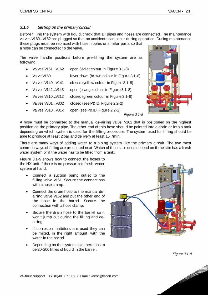
3.1.5 Setting up the primary circuit
Before filling the system with liquid, check that all pipes and hoses are connected. The maintenancevalves V160…V162 are plugged so that no accidents can occur during operation. During maintenancethese plugs must be replaced with hose nipples or similar parts so thata hose can be connected to the valve.
The valve handle positions before pre-filling the system are asfollowing:
Valves V161...V162 open (violet colour in Figure 3.1-8)
Valve V160 lever down (brown colour in Figure 3.1-8)
Valves V140...V141 closed (yellow colour in Figure 3.1-8)
Valves V142…V143 open (orange colour in Figure 3.1-8)
Valves V210…V212 closed (green colour in Figure 3.1-8)
Valves V301...V302 closed (see P&ID, Figure 2.2-2)
Valves V310...V31x open (see P&ID, Figure 2.2-2)Figure 3.1-8
A hose must be connected to the manual de-airing valve, V162 that is positioned on the highestposition on the primary pipe. The other end of this hose should be pointed into a drain or into a tankdepending on which system is used for the filling procedure. The system used for filling should beable to produce at least 2 bar and delivery at least 15 l/min.
There are many ways of adding water to a piping system like the primary circuit. The two mostcommon ways of filling are presented next. Which of these are used depend on if the site has a freshwater system or if the water has to be filled from a tank.
Figure 3.1-9 shows how to connect the hoses tothe HX-unit if there is no pressurized fresh-watersystem at hand.
Connect a suction pump outlet to thefilling valve V161. Secure the connectionswith a hose clamp.
Connect the drain hose to the manual de-airing valve V162 and put the other end ofthe hose in the barrel. Secure theconnection with a hose clamp.
Secure the drain hose to the barrel so itwon’t jump out during the filling and de-airing.
If corrosion inhibitors are used they canbe mixed, in the right amount, with thewater in the barrel.
Depending on the system size there has tobe 20-200 litres of liquid in the barrel.
Figure 3.1-9

22 • VACON COMMISSIONING
Tel. +358 (0)201 2121 • Fax +358 (0)201 212 205
Figure 3.1-10 shows how to connect the hoses to the HX-unit if there is a pressurized fresh-watersystem at hand.
Connect the hose from the faucet to thefilling valve V161. Secure theconnections with a hose clamp.
Connect the drain hose to the manualde-airing valve V162 and put the otherend of the hose into a drain. Secure theconnection with a hose clamp.
Secure the drain hose to the drain so itwon’t jump out during the filling and de-airing.
For adding corrosion inhibitor readchapter 3.1.7.
Figure 3.1-10
If a local sink or floor-drain is used and corrosion inhibitors are added to the liquid in the primarycircuit then it is the customer and/or end-user’s responsibility to check that the coolant mix can bedisposed of through the local sewer system.3.1.6 Adding liquid and de-airing
Follow the instructions for the pre-filling process before starting the pump at commissioning orafter maintenance.
How to fill the primary circuit HXT070-PS01 (See P&ID in Figure 2.2-2):
1. Prepare the unit according to the recommendations in chapter 3.1.5 Setting up the primarycircuit. Use valve V161 to regulate the flow during the filling and de-airing of the unit.
2. It is recommended that the flow, from the external pump or water supply system, is low inthe beginning of the filling process. This ensures that a minimum amount of air pockets isleft in the piping.
3. Close valve V161. Open the faucet or start the external pump depending on which fillingsystem you are using. Slowly open valve V161 to a 30-50% of maximum.
4. After a short while liquid starts to come out of the drain-hose (connected to the valve V162).During the first minutes you will hear a rattling sound in the pipes. This is the air transportedout of the system by the water. After the rattling sound stops you should open the filling valveV161 to 100%.
5. Keep the water flowing until you can’t hear any more rattles, and then close the V161 valve.Also close all the main drive valves, V310…V3xx, both the inlet and the outlet valves.
Now it is time to de-air the drives. De-air the main drives one hose pair at a time, for example V310and V311 (See Figure 2.2-2):
6. Open valve V310 first then valve V311, this means that this path will be the only way for thewater to pass when you continue filling. Then open the filling valve V161. The water will againcome out from the hose connected to the manual de-airing valve V162. Keep the waterrunning until the rattling sound disappears, that is to say the air has been removed afterwhich the V161 filling valve is closed again.
7. Close the valve V310 first, and then the valve V311. This procedure will leave the specificdrive section filled with water.

COMMISSIONING VACON • 23
24-hour support +358 (0)40 837 1150 • Email: [email protected]
8. Repeat this procedure until every frequency converter/inverter is de-aired, that is, open thevalve V312 and V313 next and so on.
9. After all the main drive hoses have been de-aired and closed, open valve V140…V141 andthen open the filling valve V161. After no more rattling can be heard due to air in the system,close valve V162, the manual de-airing valve.
10. When valve V162 is closed the pressure (see at the PI11, pressure indicator) will start to risein the primary system. When the pressure in the primary system has raised to two (2) barclose the V161 filling-valve. If you are using an external pump for adding the water it can nowbe turned off.
11. Keep the two (2) bar pressure for about 10 minutes, letting the air bubbles in the system riseup to the HX11 heat exchanger. Then open the manual de-airing valve V162 to let thepressure back down to 1.5 bar. Close valve V162.
12. Now the system is almost completely de-aired. After this the pumps must be run for shortperiods to get the rest of the air out from the HX-unit. Refer to chapter 3.4.1 Starting thepump for the rest of the de-airing instructions.
The pre-pressure in the primary circuit should be set to 1.5 bar. During operation the pre-pressureshould be between 1.0 to 1.5 bar. If the pre-pressure is reduced to below 1.0 bar during operationliquid must be added. The HX control unit will generate a ‘Low-pressure’ alarm if the pre-pressureis below 0.5 bar.
3.1.7 Adding corrosion inhibitor when using a fresh water system
If you are using a fresh water system to add water it is more difficult to add the corrosion inhibitor.The corrosion inhibitor can be added through the manual de-airing valve V162. To do this the waterlevel has to be lowered in the HX11 and a funnel has to be used (Figure 3.1-11).
1. The corrosion inhibitor should be added after all the main drives have been de-aired. Checkthat all the main drive valves, V310...V3xx, are closed.
2. Lower the liquid level in the plate heat exchanger HX11 by opening the valve V301 (or V210)and letting out 2 litres of water. This will lower the level inside the HX11 and make thenecessary space for the corrosion inhibitor.
3. Remove the hose from the valve V162 and replace it with a one (1) meter long hose. Connecta funnel to the loose end of the hose.
4. Keep the funnel higher up than the heat exchanger HX11, and pour the corrosion inhibitorinto the HX11 using a jug. Refer to the Cortec VpCl-649 product description for calculatingthe right amount of corrosion inhibitor (refer to the technical specifications for Cortec foundin the Commissioning and Maintenance folder).
If the external water system used for the filling can produce more than 6 barsthere is a risk of the safety valve (V120) opening. This might cause unnecessaryproblems if some particles are left on the sealing surface of the safety valve andtherefore causing a leak. If this happens the safety valve must be cleaned.

24 • VACON COMMISSIONING
Tel. +358 (0)201 2121 • Fax +358 (0)201 212 205
5. After all the corrosion inhibitor is added use thesame jug to fill the HX11 all the way up withwater. When no more water will go into the HX11then close the manual de-airing valve V162 andremove the hose.
6. Now open the filling valve V161 and increase thepressure back to 1.5 bar. The corrosion inhibitorwill get mixed when the pump is rotated for awhile.
Figure 3.1-11

COMMISSIONING VACON • 25
24-hour support +358 (0)40 837 1150 • Email: [email protected]
3.2 STEP 2, ELECTRICAL PART
Only qualified and authorized electricians are allowed to perform electrical workon the HX-unit.
3.2.1 Power supply
The HX-unit uses 3 ~, 400 VAC (50Hz) or 3 ~, 440VAC (60Hz), 16 A power supply. There are twoalternatives to bring the supply cables to HX-unit:from under or from above (Figure 3.2-1, Figure3.2-2).
Figure 3.2-1 Figure 3.2-2
Connect the power supply to the motor protection relay (marked green inFigure 3.2-3) in the HX-unit electrical box.
Figure 3.2-3
3.2.2 Signal cables
A signal cable must be connected between the main drive and the HX-unitelectrical box. It should be connected from the main drive basic I/O boardNXOPTA1, terminal number 6 or 12 (24V out) to the HX-unit X1 terminal block(marked green in Figure 3.2-4) terminal number 16 (cooling OK in), and backfrom X1, terminal number 17 (cooling OK out) to the main drive, terminalnumber 14 (DI 4). For more information refer to the project specific electricaldiagram and to the Vacon NX Liquid Cooled drive User’s Manual that issupplied with the main drives.
Figure 3.2-4
A 24V auxiliary voltage from the main drive is sent through the cable to the HX-unit. If the HX-unit isworking within the preset parameters then the signal is rerouted back to the main drive. When thesignal is active in the main drive basic I/O board NXOPTA1 (terminal number 14), then the main driveapplication will activate a ‘Cooling OK’ function that will allow starting and operating the main drive(=”Run Enable”).
When a flow fault or high temperature fault is active in the HX-unit, the digital output (“cooling OK”)contact in the HX control unit will disconnect the 24V signal and the main drives will shut down. Themain drive cannot be brought online before the flow fault or high temperature fault is removed.

26 • VACON COMMISSIONING
Tel. +358 (0)201 2121 • Fax +358 (0)201 212 205
3.3 STEP 3, CONTROL UNIT SETUP
3.3.1 Basic setup
The control unit application includes ‘Flow control’ parameters that have to be modified for everyproject. Primary circuit inlet temperature and primary circuit flow are two equally importantquantities that have to be monitored at all times. How to calculate the optimum flow is found inchapter 3.4.2, Adjusting the system flow and setting the switch point of the FTSA11. How to correctlyset up temperature alarms and shutoffs is found in chapter 3.3.6, Temperature set points.
If the customer and/or end-user cause a malfunction in the HX-unit or the maindrive by neglecting the parameter setup instructions in this manual, thewarranty is no longer valid.
To modify the ‘Flow control’ parameters one has to be able to use the NXP control panel.Information on how to operate the NXP control panel is found in the Vacon NX Liquid Cooled User’sManual that is supplied with the HX-unit.
The control unit also includes a Fieldbus uplink card (Profibus). The customer can use this uplink toget any of the Vacon NXP parameter values linked to a ‘higher’ control system. By using this uplinkthe customer can monitor the HX-unit from an external interface at a chosen location. Moreinformation regarding this uplink interface is found in the Vacon NX Liquid Cooled User’s Manualthat is supplied with the HX-unit.
3.3.2 Application parameter list
The application parameters and their default values are shown in table 3.3-1. The project specificparameters are calculated using the rules found in chapters 3.3.6 to 3.3.7. The values that are usedwhen setting up the HX-unit during commissioning should be written down in the ‘Custom, settings’column. If the values must be changed at a later time the new value should be written in the lastcolumn (Changes, customer). The parameters that must be edited at commissioning are markedwith a *) in the table 3.3-1. More information about these parameters is found in chapter 3.3.3,Parameter description.
COMMISSIONING VACON • 27
24-hour support +358 (0)40 837 1150 • Email: [email protected]
3.3.3 Parameter description
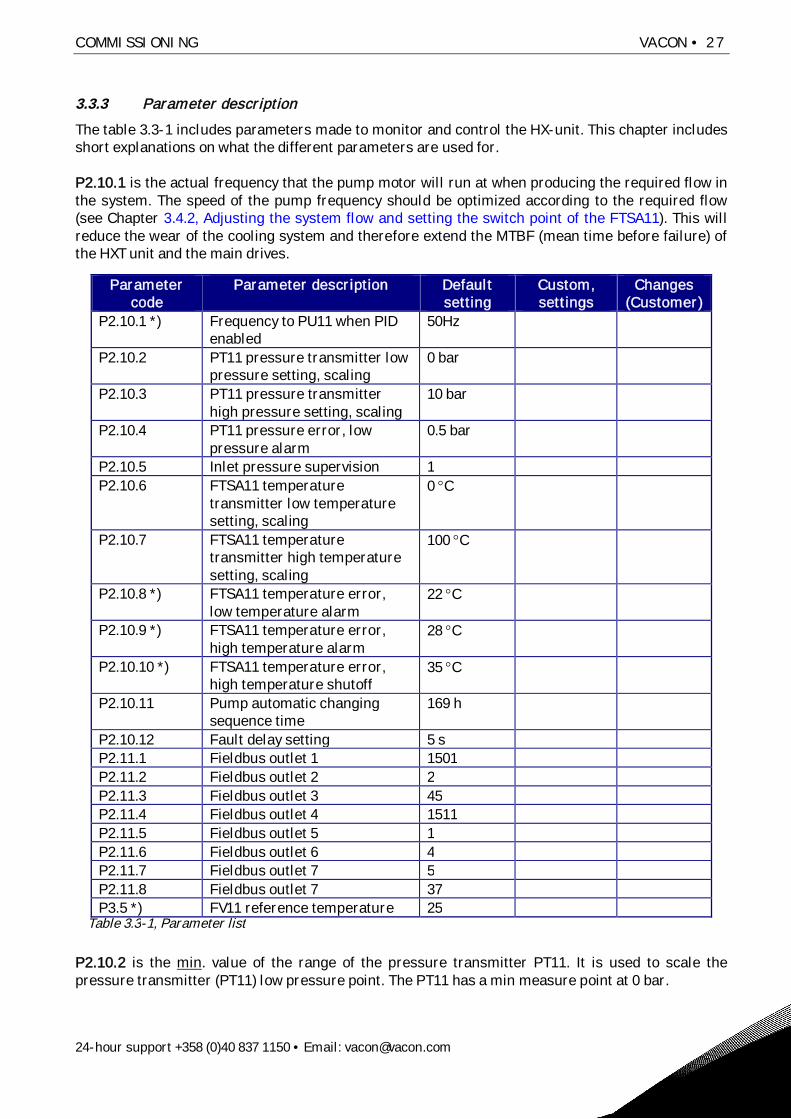
The table 3.3-1 includes parameters made to monitor and control the HX-unit. This chapter includesshort explanations on what the different parameters are used for.
P2.10.1 is the actual frequency that the pump motor will run at when producing the required flow inthe system. The speed of the pump frequency should be optimized according to the required flow(see Chapter 3.4.2, Adjusting the system flow and setting the switch point of the FTSA11). This willreduce the wear of the cooling system and therefore extend the MTBF (mean time before failure) ofthe HXT unit and the main drives.
P2.10.2 is the min. value of the range of the pressure transmitter PT11. It is used to scale thepressure transmitter (PT11) low pressure point. The PT11 has a min measure point at 0 bar.
Parametercode
Parameter description Defaultsetting
Custom,settings
Changes(Customer)
P2.10.1 *) Frequency to PU11 when PIDenabled
50Hz
P2.10.2 PT11 pressure transmitter lowpressure setting, scaling
0 bar
P2.10.3 PT11 pressure transmitterhigh pressure setting, scaling
10 bar
P2.10.4 PT11 pressure error, lowpressure alarm
0.5 bar
P2.10.5 Inlet pressure supervision 1P2.10.6 FTSA11 temperature
transmitter low temperaturesetting, scaling
0 C
P2.10.7 FTSA11 temperaturetransmitter high temperaturesetting, scaling
100 C
P2.10.8 *) FTSA11 temperature error,low temperature alarm
22 C
P2.10.9 *) FTSA11 temperature error,high temperature alarm
28 C
P2.10.10 *) FTSA11 temperature error,high temperature shutoff
35 C
P2.10.11 Pump automatic changingsequence time
169 h
P2.10.12 Fault delay setting 5 sP2.11.1 Fieldbus outlet 1 1501P2.11.2 Fieldbus outlet 2 2P2.11.3 Fieldbus outlet 3 45P2.11.4 Fieldbus outlet 4 1511P2.11.5 Fieldbus outlet 5 1P2.11.6 Fieldbus outlet 6 4P2.11.7 Fieldbus outlet 7 5P2.11.8 Fieldbus outlet 7 37P3.5 *) FV11 reference temperature 25
Table 3.3-1, Parameter list

28 • VACON COMMISSIONING
Tel. +358 (0)201 2121 • Fax +358 (0)201 212 205
P2.10.3 is the max. value of the range of the pressure transmitter PT11. It is used to scale thepressure transmitter (PT11) high pressure point. The PT11 has a max measure point at 10 bar.
P2.10.4 is a PT11 low temperature, alarm limit. The default setting for this is set at 0.5 bar. Moreinformation can be found in chapter 3.3.8, Low-pressure alarm.
P2.10.5 is a selection parameter that should be set to 1. If the PT11 pressure transmittermalfunctions the parameter can be set to 0 therefore overriding the pump suction side pressuresupervision. The pressure transmitter MUST BE REPLACED as soon as possible, the warranty is notvalid if this parameter is set to “0”.
P2.10.6 is the min. value of the range of the temperature transmitter FTSA11. It is used to scale thetemperature transmitter (FTSA11) low-temperature point. The FTSA11 has a min measure point at 0°C.
P2.10.7 is the max. value of the range of the temperature transmitter FTSA11. It is used to scale thetemperature transmitter (FTSA11) high-temperature point. The FTSA11 has a max measure point at100°C.
P2.10.8 is a FTSA11 low-temperature, alarm limit. The default setting for this is set at 22°C. Moreinformation can be found in chapter 3.3.7, Temperature alarm settings.
P2.10.9 is a FTSA11 high-temperature, alarm limit. The default setting for this is set at 28°C. Moreinformation can be found in chapter 3.3.7, Temperature alarm settings.
P2.10.10 is a FTSA11 high-temperature, trip limit. The default setting for this is set at 35°C. Thismeans that the drive will shut down (‘cooling OK‘ signal going to the main drives will bedisconnected) when the temperature is over 35°C. The HXT unit will stay online (pump running).More information can be found in chapter 3.3.7, Temperature alarm settings.
P2.10.11 the default setting is 169 ‘hours’. If the setting is between 1-168 (hour) the system will tryto change the pumps according to the time setting. This is to be used ONLY when operating the HX-series model HXT070 (double pumps). If this value is set to 0h, the pump change will occur every 30seconds. This is useful for testing and commissioning purposes because all shutoffs are alsodeactivated during these 30 seconds. The value, 169, will deactivate the attempt to change the pumpand should be used when operating the HXS070.
P2.10.12 is the parameter that sets the delay time between when the parameters are exceeded andthe activation of a warning/shutdown. The value can be varied from 1 to 5 seconds. The defaultsetting is 5 seconds. During commissioning and maintenance the value is to be set to 5 seconds.
P2.11.1-8 are parameters for the Fieldbus (Profibus) output. The customer and/or end-user canchoose any 8 of the NXP 0009 parameters to be sent out to a higher control system for externalmonitoring. The default values are as follows:
- P2.11.1, Primary side temperature from FTSA11 (°C)- P2.11.2, HX pump motor speed (rpm)- P2.11.3, HX pump motor current (A)- P2.11.4, Primary side pump inlet pressure (bar)- P2.11.5, Output frequency to HX pump motor (Hz)- P2.11.6, Motor torque as % (+1000 equals +100%)- P2.11.7, Motor shaft power in % (1000 equals 100%)- P2.11.8, Fault (trip) history

COMMISSIONING VACON • 29
24-hour support +358 (0)40 837 1150 • Email: [email protected]
P3.5 is the FV11 actuator reference temperature. Default value is 25 °C. This value is the liquid inlettemperature value to the main drives. More information can be found in chapter 3.3.6 Temperatureset points.
NOTE
Only an authorized person is allowed to make changes to the parametersettings. If the drive or HXT unit is malfunctioning or if they break due to acustomer and/or end-user parameter setup error the warranty is not valid.
3.3.4 General information about alarms and shutoff limits
Apart from the standard NXP frequency converter alarms, found in the Vacon NXP User’s Manual,the HX-unit application can generate alarms or shut-offs from one flow switch (FTSA11) with a builtin analogue temperature transmitter, a pressure sensor (PT11) and one leak sensor (LS11). Allalarm and shutoff limits have a default value. These default values should, if needed, be modified atthe commissioning phase.
NOTE
Refer to the Vacon NX USER’S MANUAL to change the parameters. Onlyauthorized personnel are allowed to make modifications to the parameters.
The parameters and their settings can be found in chapter 3.3.2, Application parameter list. Whenyou change the default settings during commissioning, you should write down the new settingincluding the date and your name to keep track of changes. Write down the new parameters to thecustom setting column of the flow control parameter table 3.3-1.
3.3.5 FTSA11 flow switch function
The flow switch is set to shut down the HX-unit if the flow does not meet the requirements, refer tochapter 3.4.2, Adjusting the system flow and setting the switch point of the FTSA11. The unit settingsshould be modified, during commissioning, through the switch interface panel. The default settingfor the switch is 50% (050).
Adjusting the FTSA11 flow switch:
1. Turn the pump power switch (the black and red switch in Figure 2.2-7) to the position “1” toconnect the power to the HX-unit. This will activate the FTSA11.
2. When the power is connected, the display flashes for approximately 30 seconds with “888”for initialization. When the flashing stops, the device is ready for programming.
30 • VACON COMMISSIONING
Tel. +358 (0)201 2121 • Fax +358 (0)201 212 205
"2" 2
1 "2""1" 2actual switching
point"12"
normally closed"n.c."
normally open"n.o."
(standard)
"on"
"oFF"(standard)
switching pointtemperature
"SPt"
normally open /normally closed
"0-C"
high range"HI"
low range"L0"
measurementrange"rAn"
End
small hysteresis"h05"
standardhysteresis
"h10"
1 "3" 3
1 "2" 3 1 2 "3""1" 2 3actual switching
point"123"
hysteresis"HuS"
switching point"SP"
switching output"S0"Start
2x2x
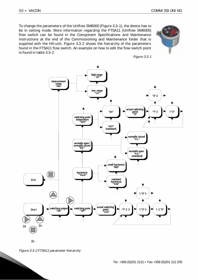
To change the parameters of the Uniflow SW6000 (Figure 3.3-1), the device has tobe in setting mode. More information regarding the FTSA11 (Uniflow SW6000)flow switch can be found in the Component Specifications and MaintenanceInstructions at the end of the Commissioning and Maintenance folder that issupplied with the HX-unit. Figure 3.3-2 shows the hierarchy of the parametersfound in the FTSA11 flow switch. An example on how to edit the flow switch pointis found in table 3.3-2.
Figure 3.3-1
Figure 3.3-2 FTSA11 parameter hierarchy
2x

COMMISSIONING VACON • 31
24-hour support +358 (0)40 837 1150 • Email: [email protected]
Table 3.3-2 shows an example on how to set the flow switching point to 68.
Description Push buttons Display1. Change to setting mode 2 x , 2 x , 2 x “SO” (switching output)
2. 1 x “SP” (switching point)
3. 1 x “050” (actual switching point)
4. Display hundred digit 1 x “050” (hundred digit isflashing)
5. Display ten digit 1 x “050” (ten digit is flashing)
6. Increase ten digit 1 x “060” (ten digit is flashing)
7. Display one digit 1 x “060” (one digit is flashing)
8. Increase one digit 8 x “068” (one digit is flashing)
9. Save new switching point 4 x “068”, “SP”, “SO”, “123”(actual flow)
Table 3.3-2 Setting flow switching point
The settings on the FTSA11 should be the following:
Measuring range, HI, high range 30 to 300 cm/s.Hysteresis, h05, 5% hysteresis.Switching order, n.c, normally closed.Temperature switch, OFF, no temperature switch point used.Flow switch point, according to calculations in chapter 3.4.2, Adjusting the system flow andsetting the switch point of the FTSA11.
3.3.6 Temperature set points
If the primary circuit temperature isn’t set correctly the main drive might malfunction because ofcondensation. The default setting of the parameter P3.5 in the HX control unit application is 25°C.This means that the 3-way valve adjusts the flow in the primary circuit to keep the liquidtemperature at 25°C (measured by the FTSA11 before the drives).
There are three factors that will affect the nominal temperature of the primary circuit:Ambient maximum temperature at the main drive installationAmbient maximum relative humidity at the main drive installationSecondary circuit maximum temperature
All of these factors have to be taken into consideration when calculating the primary circuittemperature set point.
If the humidity is high, condensation will occur in the piping inside the main drives andtherefore cause a malfunction.If the ambient temperature is too high the load of the drive must be reduced.And if the customer and/or end-user have an existing cooling system, which is going to beconnected to the secondary circuit, the temperature of this circuit might be the decidingfactor.
The primary circuit temperature is individual for every project. Here are three examples that showhow the primary circuit temperature is calculated depending on which of the three above-mentionedfactors is the deciding one:

32 • VACON COMMISSIONING
Tel. +358 (0)201 2121 • Fax +358 (0)201 212 205
Example 1, high ambient temperatureIf the customer and/or end-user have a high ambient temperature, 35°C, at the main drive thatwould require the primary circuit temperature to be equal or higher than 35°C. This would normallyrequire a load reduction of the main drive. If the maximum relative humidity at the main drive isknown, the dew-point chart (Chart 3.3-1) can be used to determine a more optimized temperaturefor the primary circuit.
Ambient temperature = 35°CMaximum relative humidity = 60%Acc. to chart 3.3-1 Dew point is @ 26°C
It is recommended to use a 2°C safety margin. Therefore the primary circuit temperature should inthis case be set to 28°C (26°C +2°C). In this case no reduction of load in the main drive is needed,even if the ambient temperature is high, due to a rather low maximum relative humidity.
Maximum ambient temperature +35°CMaximum ambient relative humidity 60%
Primary circuit minimum +28°C (26°C+2°C)
Secondary circuitmaximum +23°C(28°C-5°C)
VACON LIQUID COOLED NX DRIVE HXT070
Figure 3.3-3 Example 1
The secondary circuit maximum temperature should always be 5°C lower that the primary circuittemperature to ensure a good thermal load transfer between the two circuits. In example 1 thismeans that the secondary circuit should be between +5...+23°C during operation. The 3-way valvewill then keep the primary circuit temperature at 28°C regardless of the main drive load.
Example 2, high ambient relative humidityIf the customer and/or end-user have a high ambient temperature, 40°C, at the main drives thatwould require the primary circuit temperature to be equal or higher than 40°C. This would normallyrequire a significant load reduction of the main drive. If the maximum relative humidity at the maindrive is known, the dew-point chart can be used to determine a more optimized temperature for theprimary circuit.
Ambient temperature = 40°CMaximum relative humidity = 80%Acc. to chart 3.3-1 Dew point is @ 36°C

COMMISSIONING VACON • 33
24-hour support +358 (0)40 837 1150 • Email: [email protected]
It is recommended to use a 2°C safety margin. Therefore the primary circuit temperature should inthis case be set to 38°C (36°C +2°C). Using a 38°C temperature, instead of 40°C, on the primarycircuit will reduce the required load reduction of the main drive. For more information regarding theload reduction of the drives refer to the Vacon NX Liquid Cooled User’s Manual that is supplied withthe main drive.
Maximum ambient temperature +40°CMaximum ambient relative humidity 80%
Primary circuit minimum +38°C (36°C+2°C)
VACON LIQUID COOLED NX DRIVESecondary circuitmaximum +33°C(38°C-5°C)
HXT070
Figure 3.3-4 Example 2
The secondary circuit maximum temperature should always be 5°C lower that the primary circuittemperature to ensure a good thermal load transfer between the two circuits. In example 2 thismeans that the secondary circuit should be between +5...+33°C during operation. The 3-way valvewill then keep the primary circuit temperature at 38°C regardless of the main drive load.
Example 2b, reducing the ambient relative humidityIf the load reduction isn’t acceptable for the specified drive it is recommended that a humidityremover be installed that can reduce the maximum RH to an acceptable level. In example 2, areduction of the maximum RH from 80% to 50% will allow the primary circuit temperature to be30°C and therefore give the possibility to run the main drive at full load.
Ambient temperature = 40°CMaximum relative humidity = 80% 50%Acc. to chart 3.3-1 Dew point is @ 28°C
When adding the safety margin of 2°C the primary circuit temperature can be set to 30°C. In thiscase a reduction of the maximum RH from 80% to 50%, by using a humidity remover, will allow theprimary circuit temperature to be set to 30°C therefore allowing the main drives to be run at fullload.

34 • VACON COMMISSIONING
Tel. +358 (0)201 2121 • Fax +358 (0)201 212 205
Maximum ambient temperature +40°CMaximum ambient relative humidity 50%
Primary circuit minimum +30°C (28°C+2°C)
VACON LIQUID COOLED NX DRIVESecondary circuitmaximum +25°C(30°C-5°C)
HXT070
Figure 3.3-5 Example 2b
The secondary circuit maximum temperature should always be 5°C lower than the primary circuittemperature to ensure a good thermal load transfer between the two circuits. In example 2b thismeans that the secondary circuit should be between +5...+25°C during operation. The 3-way valvewill then keep the primary circuit temperature at 30°C regardless of the main drive load.
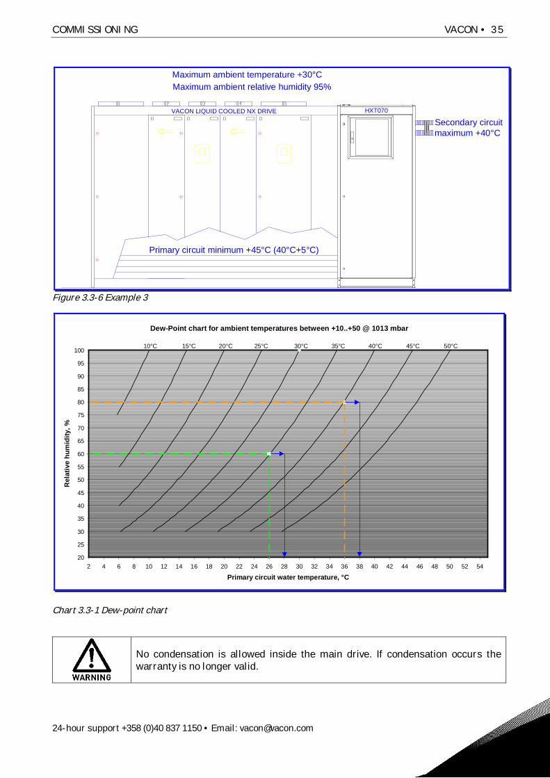
Example 3, high secondary circuit temperatureIf the customer has an existing cooling system that delivers liquid at a temperature of 40°C then theprimary circuit temperature has to be 5°C warmer to maintain a sufficient heat transfer between theprimary and secondary circuit. This means that the primary circuit temperature cannot be colderthan 45°C. This results in a significant reduction of the main drive load. In this case the only way ofincreasing the load of the main drive is to lower the temperature in the secondary circuit byinstalling additional coolers or a new cooling system with a lower water temperature. Next the dewpoint must be checked.
Secondary circuit maximum temperature = 40°CPrimary circuit maximum temperature = 45°C (40°C+5°C)Ambient temperature = 30°CMaximum relative humidity = 95%
Because the ambient temperature is beneath the primary circuit temperature there is no risk ofcondensation in the main drive.
COMMISSIONING VACON • 35
24-hour support +358 (0)40 837 1150 • Email: [email protected]
Maximum ambient temperature +30°CMaximum ambient relative humidity 95%
Primary circuit minimum +45°C (40°C+5°C)
VACON LIQUID COOLED NX DRIVE
Secondary circuitmaximum +40°C
HXT070
Figure 3.3-6 Example 3
Dew-Point chart for ambient temperatures between +10..+50 @ 1013 mbar
20
25
30
35
40
45
50
55
60
65
70
75
80
85
90
95
100
2 4 6 8 10 12 14 16 18 20 22 24 26 28 30 32 34 36 38 40 42 44 46 48 50 52 54
Primary circuit water temperature, °C
Rel
ativ
e hu
mid
ity, %
10°C 15°C 20°C 25°C 30°C 35°C 40°C 45°C 50°C
Chart 3.3-1 Dew-point chart
No condensation is allowed inside the main drive. If condensation occurs thewarranty is no longer valid.

36 • VACON COMMISSIONING
Tel. +358 (0)201 2121 • Fax +358 (0)201 212 205
Note that some Vacon liquid-cooled drives have a maximum ambient temperature of 40°C thatwould make a scenario with an ambient temperature over 40°C impossible. In a case like this it isrecommended to add a water/air condenser with built in fan to reduce the temperature inside themain drive cubicle. If a water/air condenser is used to regulate the temperature inside the maindrive cubicle the drive must be made airtight (e.g. IP54).
A last resort is to install an air conditioner that can regulate both the humidity and the temperatureat the installation (electrical room). This is a safe but usually a very expensive option.
If the temperature of the liquid in the secondary circuit is lower than the room temperature, and therelative humidity is high, condensation might occur on the secondary circuit piping and the plateheat exchanger inside the HX-unit. This is not dangerous, however nor is it desirable. If thereappears condensation inside the HX-unit it might trigger the leak sensor (LS11) on the HX-unit floorand therefore giving some ‘false’ leak alarms. In a case like this it is recommended that thecustomer insulate the secondary circuit piping and the plate heat exchanger inside the HX-unit tostop the condensation and therefore avoid any more ‘false’ alarms.
On request the HX-unit secondary circuit and the plate heat exchanger can be insulated beforedelivery.
3.3.7 Temperature alarm settings
The temperature alarm levels depend on the primary circuit temperature set point. Refer to chapter3.3.6, Temperature set points.
The over temperature alarmActivates a function that will activate the yellow indicator light on the HX-unit electrical box.The value is set to 3°C higher than the primary circuit temperature set point. The defaultsetting of the high-temperature shutoff is 28°C.When this alarm is activated the HX-control unit panel will show the text ‘A83 OverTempA’.
Example, over temperature alarmThe primary circuit temperature set point is set to 35 degrees, then the over temperature alarmparameter (P2.10.9) should be set to 38 degrees.
The over temperature faultActivates a function that will shut down the drives but will keep the HX-unit running, is set to10°C higher than the primary circuit temperature set point. The default setting of the high-temperature shutoff is 40°C.When this alarm is activated the HX-control unit panel will show the text ‘A83 OverTempA’.And both the red and the yellow indicators on the electrical box will be active.
Example, over temperature faultThe primary circuit temperature set point is set to 35 degrees, then the over temperature faultparameter (P2.10.10) should be set to 45 degrees.
The HX-unit over temperature fault is designed to work as protection in case of a sudden change inthe primary circuit for example if the flow in the secondary circuit for some reason is stopped.

COMMISSIONING VACON • 37
24-hour support +358 (0)40 837 1150 • Email: [email protected]
The low temperature alarmActivates a function that will activate the yellow indicator light on the HX-unit electrical box.The parameter is set to 3°C lower than the primary circuit temperature set point. The defaultsetting of the high-temperature shutoff is 22°C.When this alarm is activated the HX-control unit panel will show the text ‘A86 LowTemp’.
Example, low temperature alarmThe primary circuit temperature set point is set to 35 degrees, and then the low temperature alarmshould be set to 32 degrees.
Example, all temperature valuesA primary circuit temperature set point of 35°C has been calculated for a specific installation. Thetemperature parameters should be adjusted the following way:
The primary circuit temperature set point (parameter P3.5) is set to 35°C
New over-temperature alarm value (parameter 2.10.9) 38°C
New low-temperature alarm value (parameter 2.10.8) 32°C
New over-temperature fault value (parameter 2.10.10) 45°C
The parameters are modified by using the HX Control box interface (Vacon NXP frequency converterpanel). Instructions on how to access and modify the parameters can be found in the Vacon NXPUser’s Manual that is supplied with the HX-unit.
3.3.8 Low pressure alarm
The function of the pressure sensor placed on the pump suctions side is to give the user a warning oflow pressure before the FTSA11 flow switch generates a sudden unwanted shutdown. If there is aleak in the primary circuit, outside of the HX-unit, the pressure starts to reduce in the system. Theset point for the pressure sensor is 0.5 bar, so if the pressure on the primary circuit suction sidegoes under 0.5 bar the yellow indicator light on the electrical box will activate. The correct systempre-pressure is found in the chapter 3.1.6, Adding liquid and de-airing.
If the suction pressure in the primary circuit is reduced due to a leak, the flow inthe circuit will within a short period of time be insufficient and therefore activatea FTSA11 flow switch shutdown.
The low-pressure parameter number is P2.10.4. Follow the instructions in the Vacon NXP User’sManual on how to access and modify the parameters.
3.3.9 Leak switch alarm specifications
The leak sensor is a free standing sensor on to the leakage plate in the floor of the HX-unit. Thefunction of the switch is only to alert the user, by switching on the yellow alarm indicator placed onthe control box. The leak sensor generates an alarm if there is liquid on the floor plate inside theHX-unit due to a leak in the unit. If there is condensation inside the HX-unit, the leak switch cangenerate ‘false’ leak alarms.
NOTE
Note that no condensation is allowed. However, if the relative humidity within thecubicle is high and the ambient temperature is higher than the secondary circuitinlet temperature, condensation will occur on the secondary circuit piping.

38 • VACON COMMISSIONING
Tel. +358 (0)201 2121 • Fax +358 (0)201 212 205
If the secondary circuit inlet liquid temperature is not temperature controlled by the customer, thereis a risk of condensation on the secondary circuit inlet piping.
Example: If the secondary circuit liquid inlet is 10°C and the ambient relative humidity inside theHX-unit cubical is 25% with a temperature of 20°C, condensation starts to occur in the secondarycircuit inlet piping. These values can be found on a Mollier diagram that shows the behaviour ofmoist air in normal (1.013 bar) pressure.
If any condensation occurs, the customer must add insulation on the HX11 heat exchanger and onthe secondary circuit piping, or increase the temperature in the secondary circuit inlet liquid. Themaximum temperature of the secondary circuit inlet liquid is 25°C without having to reduce the loadin the main drive. More information regarding the secondary circuit temperature is found in chapter3.3.6, Temperature set points.
3.3.10 Three-way valve actuator settings
Please check that the SW-switch is in “normal” position in electronic positioner ES11. Installationinstructions are found at the end of the HX-unit Commissioning and Maintenance folder that issupplied with the unit.

COMMISSIONING VACON • 39
24-hour support +358 (0)40 837 1150 • Email: [email protected]
3.4 STEP 4, ADJUSTING THE FLOW
3.4.1 Starting the pump
Note that de-airing of the unit has to be done before the HX-pump can be started. To start the pumpsfor the first time:
1. Open the maintenance valves for the main drives (V310 to V31x) that are to be used.
2. Check that the valves V140…V143 are open and that V160 has the lever turned downwards.
3. Check that the valves V161…V162 and V210…V212 are closed. And that the pre-pressure is at1.5 bar.
4. If the customer has added some valves these must also be in checked.
5. Check that there are no visible leaks.
6. If the electrical cables have been connected and checked, refer to chapter 3.2 STEP 2,ELECTRICAL PART, turn the main power switch (the red / yellow switch in Figure 2.2-7) toposition “1”.
7. It is recommended that the parameter P2.10.1 be changed to 30 Hz at first start-up. Laterwhen the HX-unit is completely de-aired the P2.10.1 should be set to the correct value, referto chapter 3.4.2, Adjusting the system flow and setting the switch point of the FTSA11.
8. Start up the pump PU11 or PU12 by turning the pump control switch to position “1” (the blackand red switch in Figure 2.2-7). The liquid starts to circulate in the primary circuit. Run thepump for max. 30 sec. then do the same to the other pump.
9. Wait for 5 min. and open the manual de-airing valve V162 to let out any air that might havebeen stuck in the pump housing.
10. Add water to get the pressure back up to 1.5 bars. Then start one of the pumps again andleave it running.
11. The LED-display on the FTSA11 should register that there is flow in the system. If not, stopthe pump and re-check that all valves are open, e.g. in the drive section, in the HX-unit and ifthere is piping/valves made by customer in the primary circuit then check them also. Theflow switch is set to 50% as default and has a 5 second delay (the 5 second delay isprogrammed into the HX control unit application). What this means is that the flow has to getover the 50% limit within 5 seconds of starting the pump, or the HX control unit will shutdown the pump.
12. If the pump is shut down and the HX control unit display is registering a flow fault, reset thefault from the Vacon NXP control panel, turn the pump control switch back to position “0”and try again (refer to the NXP ‘All in one’ manual on how to work the panel). If the pumpdoes not stay online after three (3) attempts, de-airing has not been done correctly or someof the valves mentioned in step 1 and 2 are still closed. De-air the system again; refer toChapter 3.1.6 Adding liquid and de-airing.
13. Check that all valves except V161…V162, V210…V212 and V301…V302 are open. If the pumpdoes not stay online after a new de-airing, try to temporarily lower the flow switching pointfor the FTSA11 to 10% (50% as default). Information on how to modify the FTSA11 switchingpoint is found in chapter 3.3.5, FTSA11 flow switch function.
The pumps must not be run dry under any circumstances. Running the pump dryeven for a short period of time might cause the shaft seal in the pump to startleaking.

40 • VACON COMMISSIONING
Tel. +358 (0)201 2121 • Fax +358 (0)201 212 205
14. If the pump stays online, run it for 15 minutes and then change the flow switch point back tothe project-specific setup value. The flow switch point can be changed during operation.
During the first days of operation, the pre-pressure decreases because some air might be left in thesystem after de-airing.
To adjust the pressure:
1. Connect a filling hose to valve V161. De-air the filling hose before adding liquid to avoid airgetting into the primary circuit.
2. Add liquid to increase the pressure back to 1.5 bar on the PI11 pressure gauge.
3. Close valve V161 and remove the hose.
3.4.2 Adjusting the system flow and setting the switch point of the FTSA11
The pump flow should be adjusted according to the required flow of the connected drives. Beforeadjusting the flow, the primary circuit has to be correctly filled and de-aired. The target flow can becalculated by adding up the nominal flow for the main drives connected to the HX-unit. Forinformation on how to calculate the optimum system flow see the example below. To adjust thesystem flow:
1. Start up the pump and run it at 50 Hz, which is the default value in the HX control unitapplication.
2. Check the actual flow speed in percent from the flow switch FTSA11 and convert it into l/minby using the converting formula.
3. Adjust the frequency of the pump to match the required total nominal flow + 10% (seeexample).
Example: If you are using 5 x Ch72 drive, the nominal flow according to the NX Liquid drive manualis 175 l/min. The flow should then be set to ‘nominal flow’ x 10%.
Adjust the flow to 193 l/min (175 x 1.1) that is 53% according the converting formula, bychanging the frequency parameter P2.10.1 in the ‘Flow control’ part of the control unitapplication. The default value of the parameter is 50Hz. Reduce the frequency by 2 Hz at atime until the FTSA11 display shows the value ~53%. The value shown on the FTSA11 issomewhat irregular in the beginning.The setting point for FTSA11 should be set at the nominal required flow -10%. The nominalflow for a Ch72 is 175 l/min, therefore the switch point should be set to 158 l/min (175 x 0.9).From the converting formula we can establish that 158 l/min corresponds to 46% on theFTSA11. Information on how to modify the switch point of the FTSA11 is found in chapter3.3.5, FTSA11 flow switch function.If the actual flow goes under 41% (set point 46% - 5% hysteresis), the FTSA11 flow switch willopen the switch (when the FTSA11 is set to ‘normally closed’, N.C). If the alarm disappearswithin 5 seconds, the control unit application filters out the alarm. If the alarm is still activeafter 5 seconds, the ‘cooling OK’ signal to the drives is disconnected, and both the HX-unitpump and the drives shut down.
Converting formula for the FTSA11 flow switch:
HXT070 AISI
x = 5 * y – 14.7 ( y = x / 5 + 14.7) , where y = FTSA11 display (%) x = flow l/min

COMMISSIONING VACON • 41
24-hour support +358 (0)40 837 1150 • Email: [email protected]
3.4.3 Checklist before starting main NX drives
After the de-airing, when the control unit setup and the flow adjustment are performed and the HX-unit has been running for 30 minutes without any alarms, the main drive can be brought online. Ifthere is more than one converter, it is recommended that they be started up one by one to avoid anysudden changes in the temperature. The load of the drives should also be increased step by step,otherwise the temperature might change too fast and cause an alarm, or in the worst case, a drivemalfunction.
Before starting the drives:
1. Check that the HX-unit flow and temperature are within the given parameter values (noalarms).
2. Check that there is no air left in the plate heat exchanger by carefully opening the manualde-airing valve V162 and letting out a small amount (about 1 centilitre) of water.
3. Check that the PI11 pressure gauge is at about 1.5 bar.
4. Check that the maintenance valves to the converters (in use) V310…V31x are open.
5. Check that the flow (refer to FTSA11 converting formula above) is according to the connectedconverter requirements.
6. Check that the primary circuit temperature is according to the setup value.
7. Check that there is no condensation in the main drive cubical. If there is condensation insidethe drive cubicles, the drives must be dried out before start-up.
After successfully performing the different steps of commissioning presented in chapter 3, the HX-unit and the connected drives are ready to be moved from the commissioning stage to operationmode. Troubleshooting information and unit service information is located in the last two chapters ofthis manual. For further information contact your local distributor.
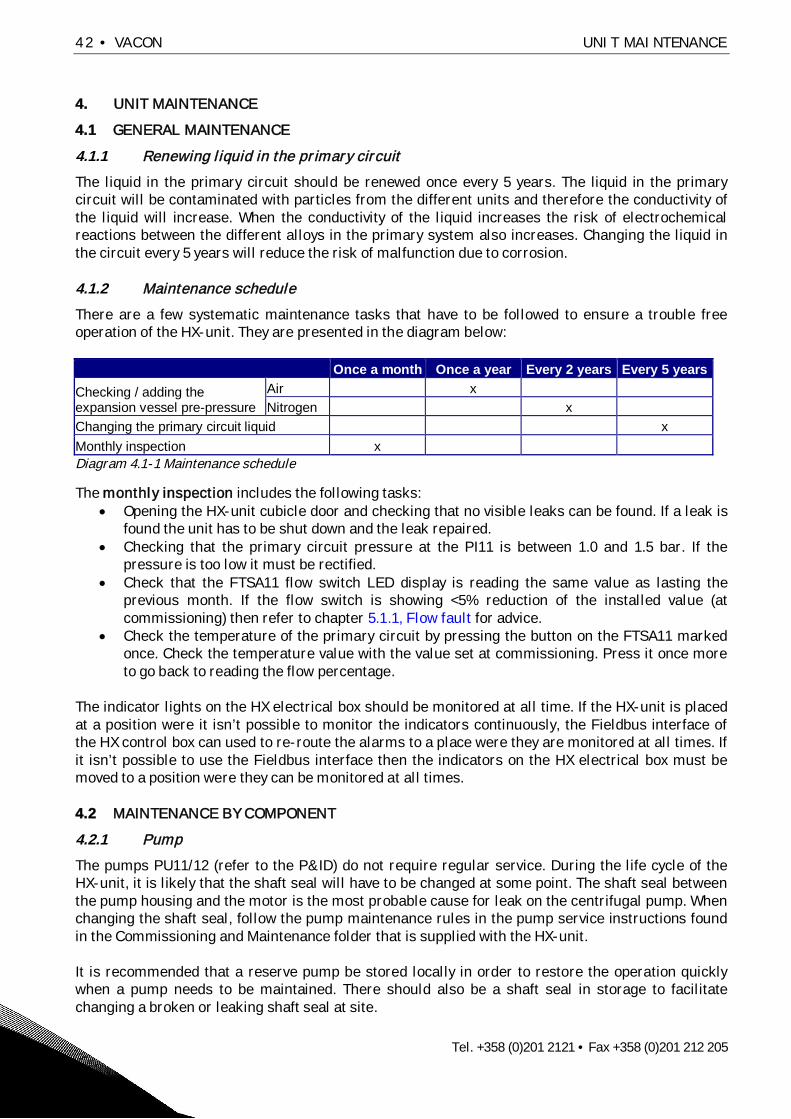
42 • VACON UNIT MAINTENANCE
Tel. +358 (0)201 2121 • Fax +358 (0)201 212 205
4. UNIT MAINTENANCE
4.1 GENERAL MAINTENANCE
4.1.1 Renewing liquid in the primary circuit
The liquid in the primary circuit should be renewed once every 5 years. The liquid in the primarycircuit will be contaminated with particles from the different units and therefore the conductivity ofthe liquid will increase. When the conductivity of the liquid increases the risk of electrochemicalreactions between the different alloys in the primary system also increases. Changing the liquid inthe circuit every 5 years will reduce the risk of malfunction due to corrosion.
4.1.2 Maintenance schedule
There are a few systematic maintenance tasks that have to be followed to ensure a trouble freeoperation of the HX-unit. They are presented in the diagram below:
Once a month Once a year Every 2 years Every 5 yearsChecking / adding theexpansion vessel pre-pressure
Air xNitrogen x
Changing the primary circuit liquid xMonthly inspection xDiagram 4.1-1 Maintenance schedule
The monthly inspection includes the following tasks:Opening the HX-unit cubicle door and checking that no visible leaks can be found. If a leak isfound the unit has to be shut down and the leak repaired.Checking that the primary circuit pressure at the PI11 is between 1.0 and 1.5 bar. If thepressure is too low it must be rectified.Check that the FTSA11 flow switch LED display is reading the same value as lasting theprevious month. If the flow switch is showing <5% reduction of the installed value (atcommissioning) then refer to chapter 5.1.1, Flow fault for advice.Check the temperature of the primary circuit by pressing the button on the FTSA11 markedonce. Check the temperature value with the value set at commissioning. Press it once moreto go back to reading the flow percentage.
The indicator lights on the HX electrical box should be monitored at all time. If the HX-unit is placedat a position were it isn’t possible to monitor the indicators continuously, the Fieldbus interface ofthe HX control box can used to re-route the alarms to a place were they are monitored at all times. Ifit isn’t possible to use the Fieldbus interface then the indicators on the HX electrical box must bemoved to a position were they can be monitored at all times.
4.2 MAINTENANCE BY COMPONENT
4.2.1 Pump
The pumps PU11/12 (refer to the P&ID) do not require regular service. During the life cycle of theHX-unit, it is likely that the shaft seal will have to be changed at some point. The shaft seal betweenthe pump housing and the motor is the most probable cause for leak on the centrifugal pump. Whenchanging the shaft seal, follow the pump maintenance rules in the pump service instructions foundin the Commissioning and Maintenance folder that is supplied with the HX-unit.
It is recommended that a reserve pump be stored locally in order to restore the operation quicklywhen a pump needs to be maintained. There should also be a shaft seal in storage to facilitatechanging a broken or leaking shaft seal at site.

UNIT MAINTENANCE VACON • 43
24-hour support +358 (0)40 837 1150 • Email: [email protected]
When the pump is leaking, remove the broken pump and replace it with a reserve pump. The brokenpump should be fixed immediately and stored for later use in case a similar pump failure occurs.Purchase a new shaft seal from the unit manufacturer, and keep this in storage as well.
High-pressure hot coolant (6 bar, +60 C) may be present in the primary coolingcircuit. The coolant consists of liquid, propylene glycol and corrosion inhibitors,depending on the project. Glycol and corrosion inhibitors are damaging for theeyes. If you get coolant in your eyes, on your skin, or in your mouth, seekmedical advice. Use safety goggles.
To change a pump:
1. Check that it is safe to turn off the drives connected to the HX-unit, and that there is enoughtime reserved for the maintenance.
2. Prepare the HX-unit for liquid filling by connecting a hose to the filling valve (V161). ReadChapter 3.1.6, Adding liquid and de-airing before continuing.
3. Take the main drives connected to the HX-unit offline, according to the Vacon NX LiquidCooled User’s Manual.
4. Shut down the power to the HX-unit by first turning both the pump control switches to “0”,therefore shutting down the pump, then turning the main power switch to position “0”, referto Figure 2.2-7.
5. Check that there is no power coming to the pumps by removing the cover of the pumpelectrical connection box and measuring the voltage. No work on the unit is allowed when thepower is connected.
6. Disconnect the electrical cables from the pump that is to be changed. Write down the orderof the phases for later use.
7. Close the maintenance valves of the pump that is to be maintained (V140-V143). Refer to theP&ID in Figure 2.2-2 or the project specific P&ID if one is available.
NOTE
If the liquid contains corrosion inhibitors or other additives then check nationalor local ecological directives for information on how to dispose of the drainedliquid. Information regarding the recommended corrosion inhibitor Cortec isfound in the end of the Commissioning and Maintenance folder that is suppliedwith the unit.

44 • VACON UNIT MAINTENANCE
Tel. +358 (0)201 2121 • Fax +358 (0)201 212 205
8. Remove the bolts and nuts from the pump motor flange.Therefore leaving the pump housing in place (Figure 4.2-1).Note that there is a pre-pressure of 1.5 bars in the system;use safety goggles.
9. Lift out the pump from the HX-unit. Note the pump weight isabout 50kg. It is recommended that there are two personspresent when the pump is removed.
10. Perform the necessary maintenance on the pump andreconnect the pump to the pump housing. Or simply replacethe pump if a spare pump is available.
11. Connect the electrical cables to the (new) pump motor.
12. Open the maintenance valves V140-V143.
13. Refill and de-air the pipes according to the instructions inchapter 3.1.5 and 3.1.6.
Figure 4.2-1
There are replacement parts available if there is a leak (e.g. shaft seal), or if the pumps are not ableto keep sufficient pressure. Refer to the technical specifications of the pump for the replacementparts. The specifications can be found in the end of the Commissioning and Maintenance folder thatis supplied with the HX-unit.
4.2.2 Heat exchanger
The heat exchanger does not need regular service. If the primary circuit temperature is too high(high-temperature alarm is active), the flow is too low in one of the circuits or the temperature in thesecondary circuit inlet is outside the defined parameter values. If the flow in the secondary circuit istoo low, there may be some biological residue clogging the heat exchanger.
Because the primary circuit is filled with clean liquid, it is unlikely that the primary circuit’s side ofthe heat exchanger clogs. Refer to the heat exchanger cleaning instructions found in the end of theCommissioning and Maintenance folder that is supplied with the HX-unit.
If the liquid used in the secondary circuit contains biological or chemical residue, it is recommendedthat a spare heat exchanger be stored locally. When the flow in the secondary circuit is too low, theHX-unit should be shut down and the heat exchanger replaced. The dirty heat exchanger should becleaned according to manufacturer’s instructions and placed in storage for the next time HX11needs to be changed.

UNIT MAINTENANCE VACON • 45
24-hour support +358 (0)40 837 1150 • Email: [email protected]
The HX11 can, if needed, be removed without removing the HX-unitfrom the cubicle:
1. Drain both the primary circuit and the secondary circuit. Thesecondary circuit is drained through the V220 valve (markedyellow in Figure 4.2-2). The primary circuit is drained throughthe valves V210 and V212 (marked green in Figure 4.2-2).
2. Disconnect the primary and secondary circuit connections(marked violet in Figure 4.2-2) from the unit. AISI pipeconnections can be opened with a box wrench. PVC-C pipeconnections can be opened by hand, or if needed use oil filterremover (used to remove the oil filter from cars). Be careful notto damage the connections.
Figure 4.2-2
3. Remove the three heat exchanger fasteners, M10 screwconnections (marked violet in Figure 4.2-3).
4. The plate heat exchanger weights about 42 kg. Carefully pull / lift /turn out the HX11 (Figure 4.2-4).
5. Replace the unit with a clean one, or clean the unit according tothe manufacturer’s instructions found in the end of theCommissioning and Maintenance folder that is supplied with theHX-unit.
Figure 4.2-3
6. Connect the clean unit in reverse order using the instructionsabove. Add liquid and de-air the unit according to the instructionsin chapter 3.1.5 and 3.1.6.
Figure 4.2-4
The manufacturer provides cleaning chemicals that improve the cleaning result. If the secondaryliquid quality is bad, it is recommended that these chemicals, and a reserve plate heat exchanger, bekept in storage.

46 • VACON UNIT MAINTENANCE
Tel. +358 (0)201 2121 • Fax +358 (0)201 212 205
4.2.3 Pressure vessel
If the vessel is pre-pressured with nitrogen, the vessel pre-pressure needs to be checked everyother year. If air is used as the pre-pressuring gas, it has to be checked once a year. In time, the gasescapes through the butyl rubber membrane into the liquid circuit, and gas or air must be added.The pre-pressure can be checked without draining the primary circuit.
It is recommended that this procedure be done during a yearly maintenance.
When performing maintenance work on a pressurized system generallyacknowledged safety standards, EU directives and national regulations mustalso be followed. Use safety goggles.
To check the pre-pressure:
1. Remove the plug on valve V160 and replace it with a hose connector.
2. Place an eight (8) litre jar under the valve (if the expansion vessel air nozzle or membrane isbroken there might be up to 8 litres in the vessel).
3. Turn the lever (marked yellow in Figure 4.2-5) on valveV160 90° so that it points away from you (pointstowards the back wall). This will close off the primarycircuit and therefore only the liquid in the expansionvessel will come out. (There is line mark in the end ofthe stem, where you can also ensure the right positionof the 3-way valve. This mark shows the open flowdirection.)
4. When the pressure vessel is drained check the pre-pressure with a portable pressure gauge. The airnozzle can be found under the black rubber top on thevessel. The portable pressure gauge should have asimilar interface to that used to fill a car tyre.
Figure 4.2-5
5. The pressure can be added with a nitrogen tank (pressure over 2 bar) or if air is used then acompressed air system or even a hand pump can be used.
6. Refill pressure if necessary. The pressure should be 100 kPa (1 bar). Use nitrogen if possible;otherwise air can also be used.
7. Reconnect the plug to valve V160, change the plug O-ring if necessary.
8. Turn back the lever on valve V160 90° so that it points down.
9. The pressure in the primary circuit will decrease due to the water that is removed during thisprocess. Therefore water must be added through the filling valve V161 until the pressure onthe pressure gauge (PI11) is back at 1.5 bar. Remember to de-air the filling hose before youconnect it to valve V161, otherwise the air in the filling hose will enter the unit during filling.
10. Due to the small amount of liquid removed during this process it is not necessary to add anycorrosion inhibitor.

TROUBLESHOOTING VACON • 47
24-hour support +358 (0)40 837 1150 • Email: [email protected]
5. TROUBLESHOOTING
5.1 Alarms and shutoffs
This chapter provides help in case the HX-control unit activates an alarm or fault. An alarm or faultis activated, because the HX-unit is working outside the parameter settings in the HX-control unit.The pre-set parameters for the HX-unit are shown in chapter 3.3.2, Application parameter list.
5.1.1 Flow fault
If the flow fault shutoff is active (acc. To panel below) the HX-unit pump has stopped and the‘Cooling OK’ signal to the main drive has been disconnected. The red indicator light on the electricalbox door is also active. Check the following issues to solve why the alarm has been activated:
Figure 5.1-1, Flow fault on the NXP panel
Malfunction Reasons for malfunction Correction measuresThe pre-pressure istoo low in the primarycircuit, i.e. below 0.5bar.
The pre-pressure in theexpansion vessel EV11has been reduced.
Check the EV11 pre-pressure and addpressure if necessary.Add pre-pressure to the primarycircuit by adding liquid through valveV161.
There is a leak in theprimary circuit.
Check the primary circuit for leaks. If aleak is found the unit must be drainedand the leak fixed before the unit isrestarted.
The pump isn’tdelivering enoughpressure i.e. the flowis too low.
A valve in the primarycircuit is closed.
Check if any of the following valves inthe primary circuit is closed (refer tothe P&ID):
V140…143V310…3xxAny valves in the primarycircuit added by thecustomer
The pump is broken. Replace the broken pump.
The FTSA11 is setincorrectly (this is afault that is mostlikely to appear duringmaintenance or at the
The flow requirementhas changed after thecommissioning stage.
Check the current flow requirements,they might have changed if e.g. aconverter is taken offline (and itsvalves closed) because ofmaintenance.
F1.87 FlowFaultF F1 F11
STOP FAULT
I/O term
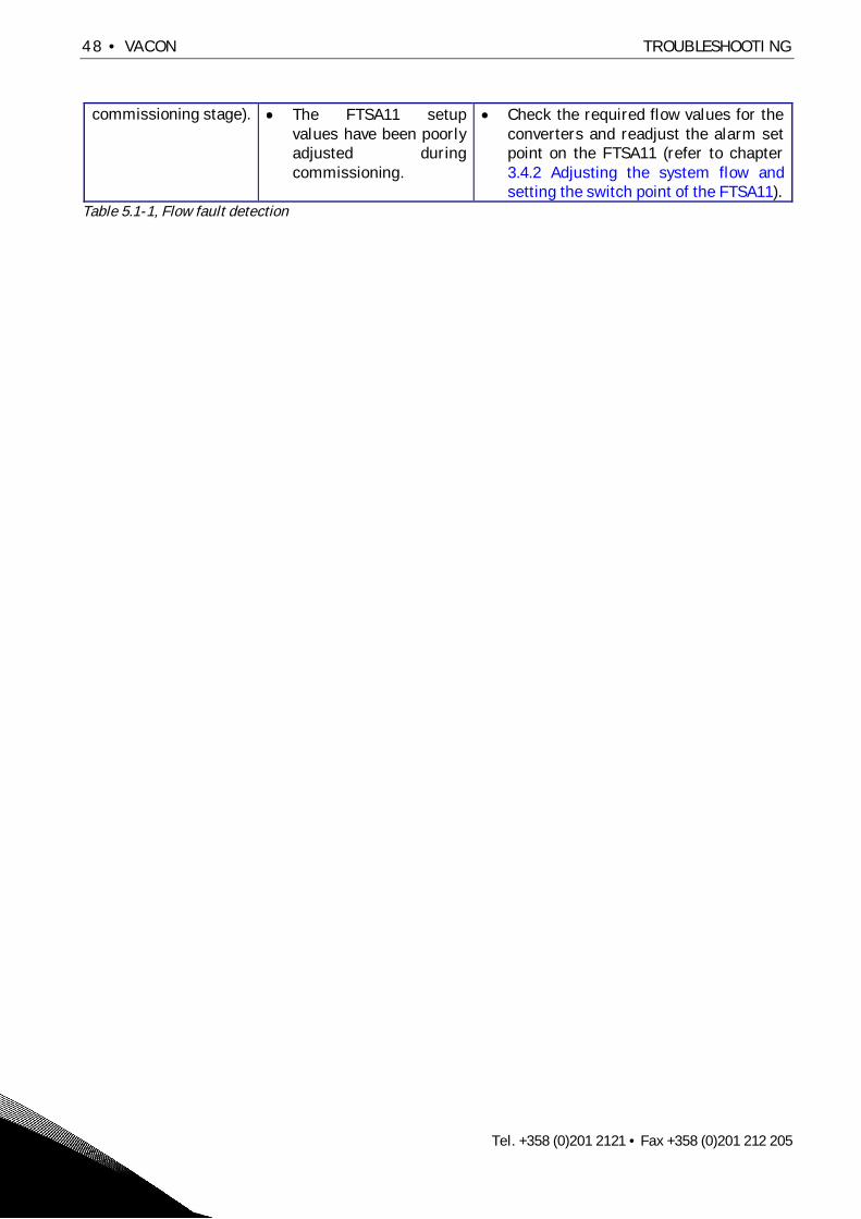
48 • VACON TROUBLESHOOTING
Tel. +358 (0)201 2121 • Fax +358 (0)201 212 205
commissioning stage). The FTSA11 setupvalues have been poorlyadjusted duringcommissioning.
Check the required flow values for theconverters and readjust the alarm setpoint on the FTSA11 (refer to chapter3.4.2 Adjusting the system flow andsetting the switch point of the FTSA11).
Table 5.1-1, Flow fault detection

TROUBLESHOOTING VACON • 49
24-hour support +358 (0)40 837 1150 • Email: [email protected]
5.1.2 Temperature alarms and shutoffs
If the high temperature alarm is active (acc. To panel below) the HX-unit is still online and the‘Cooling OK’ signal to the main drive is connected. The yellow and green indicator lights on theelectrical box door are also active. Check the following issues to solve why the alarm has beenactivated:
Figure 5.1-2, High temperature alarm on the NXP panel
Malfunction Reasons for malfunction Correction measuresThe flow in thesecondary circuit istoo low.
The customer filter,outside the HX-unit, MF21(refer to the P&ID) isclogged.
Clean the filter.
The plate heat exchangerHX11 (refer to the P&ID) isclogged on the secondaryside.
Clean the heat exchanger. Refer tothe cleaning instructions found inthe HX-unit folder that is suppliedwith the unit. Instructions on how toremove the plate heat exchangerare found in chapter 4.2.2, Heatexchanger.
The customer pump in thesecondary circuit ismalfunctioning andtherefore not able toproduce enough flow.
Maintain or replace the customercircuit pump.
The temperature ofthe secondary circuitliquid is too high.
Maintaining the HX-unitcannot solve the reason forthis malfunction.
The temperature of the liquid in thesecondary circuit inlet has to be 5degrees lower than the primarycircuit temperature set point, e.g. ifthe primary circuit temperature setpoint is set to 35°C then thesecondary circuit inlet temperaturemust be 30°C or lower.
The regulating valveV130 ismalfunctioning
The 3-way valve V130 ismalfunctioning andtherefore not directingenough flow through theplate heat exchanger toensure a satisfactory heattransfer between theprimary and secondarycircuit.
If the 3-way valve or the valveactuator is malfunctioning it mustbe replaced.
F1.83 OverTempAA T1 T16
RUN READY ALARM
I/O term

50 • VACON TROUBLESHOOTING
Tel. +358 (0)201 2121 • Fax +358 (0)201 212 205
The FTSA11 setup valueshave been wronglyadjusted duringcommissioning.
Check the project parameters (referTable 3.3-1, Parameter list) andcompare it with the actualtemperature.
Table 5.1-2 High temperature fault detection
If the high temperature shutoff is active (same panel layout as high temperature alarm) the HX-unitis online but the ‘Cooling OK’ signal to the main drive has been disconnected. The yellow and redindicator lights on the electrical box door are active. The reasons for this shutoff are the same as forthe high temperature alarm.
If the low temperature alarm is active (acc. To panel below) the HX-unit is still online and the‘Cooling OK’ signal to the main drive is connected. The yellow and green indicator lights on theelectrical box door are also active. Check the following issues to solve why the alarm has beenactivated:
Figure 5.1-3, Low temperature alarm on the NXP panel
Malfunction Reasons for malfunction Correction measuresThe regulating valveV130 (refer to theP&ID) ismalfunctioning
The 3-way valve V130is malfunctioning andtherefore directing toomuch flow through theplate heat exchanger.
If the 3-way valve or the valve actuator ismalfunctioning it must be replaced.
The inlet temperatureon the secondarycircuit is decreasingtoo fast, and the 3-wayvalve is not able toadjust the flow in theprimary circuit fastenough.
Wait for two minutes and see if the alarmis reset automatically. If the alarm is activelonger than two minutes, check the 3-wayvalve’s function. If the 3-way valve or thevalve actuator is malfunctioning it must bereplaced. If the temperature in the primarycircuit is too low it will result incondensation in the main drive section. Nocondensation is allowed.The temperature in the secondary circuitshould not be allowed to decrease orincrease too fast. A change of 1°C / minuteshould not be exceeded.
F1.86 LowTempA T1 T16
RUN READY ALARM
I/O term

TROUBLESHOOTING VACON • 51
24-hour support +358 (0)40 837 1150 • Email: [email protected]
The FTSA11 (refer tothe P&ID) flowsensor with theanalogicaltemperature outletis malfunctioning.
The FTSA11 flowsensor with theanalogicaltemperature outlet isbroken.
Check the temperature by comparing theFTSA11 temperature with the secondarycircuit temperature indicator TI21. Thetemperature of FTSA11 should be higherthan the TI21 temperature. Replace theFTSA11 if necessary.If a TI21 is not installed then check theprimary circuit temperature (using aportable measuring device) and compare itto FTSA11. To get an accurate value theportable temperature gauge must beconnected close to the FTSA11. Replacethe FTSA11 if necessary.
Table 5.1-3, Low temperature fault detection

52 • VACON TROUBLESHOOTING
Tel. +358 (0)201 2121 • Fax +358 (0)201 212 205
5.1.3 Low pressure alarm
If the low pressure alarm is active (acc. to panel below) the HX-unit is still online and the ‘CoolingOK’ signal to the main drive is connected. The yellow and green indicator lights on the electrical boxdoor are also active. Check the following issues to solve why the alarm has been activated:
Figure 5.1-4, Low pressure alarm on the NXP panel
Malfunction Reasons for malfunction Correction measuresLeak in the primarycircuit outside theHX-unit.
Loose connection. Tighten the connection until the leak stops.Add liquid to the primary circuit until thecorrect pre-pressure is reached. Followthe instructions in chapter 3.1.6, Addingliquid and de-airing.
Faulty connection. Replace the broken parts. Then add liquidto the primary circuit until the correct pre-pressure is reached. Follow theinstructions in chapter 3.1.6, Adding liquidand de-airing.
Hose failure in themain drive section.
Replace the hose. Refer to the NX LiquidCooled User’s Manual. Then add liquid tothe primary circuit until the correct pre-pressure is reached. Follow theinstructions in chapter 3.1.6, Adding liquidand de-airing.
Pressure vesselEV11 (refer to theP&ID) is withoutpre-pressure.
The gas (air ornitrogen) has escapedthrough the butylrubber membrane intothe primary circuit.
Check and refill the pre-pressureaccording to the instructions in chapter4.2.3 Pressure vessel.
The EV11 filling valveis broken andtherefore letting outgas.
Replace the valve and refill the pre-pressure according to the instructions inchapter 4.2.3 Pressure vessel.
The butyl membraneinside the expansionvessel is broken.
Replace the expansion vessel and refill thepre-pressure according to the instructionsin chapter 4.2.3 Pressure vessel.
Other reason. Faulty pressure sensor Compare the value from the pressuregauge, PI11, with the value from thepressure transmitter PT11. If the pressuretransmitter is broken it has to be replaced.
Table 5.1-4, Pressure fault detection
F1.82 InletPressLowA T1 T16
RUN READY ALARM
I/O term

TROUBLESHOOTING VACON • 53
24-hour support +358 (0)40 837 1150 • Email: [email protected]
5.1.4 Leak alarms
If the leak alarm is active (acc. to panel below) the HX-unit is still online and the ‘Cooling OK’ signalto the main drive is connected. The yellow and green indicator lights on the electrical box door arealso active. Check the following issues to solve why the alarm has been activated:
Figure 5.1-5, Leak alarm on the NXP panel
Malfunction Reasons for malfunction Correction measuresLeak Loose connection. Tighten the connection until the leak stops.
Add liquid to the primary circuit until thecorrect pre-pressure is reached. Followthe instructions in chapter 3.1.6, Addingliquid and de-airing.
Faulty connection. Replace the broken parts. Then add liquidto the primary circuit until the correct pre-pressure is reached. Follow theinstructions in chapter 3.1.6, Adding liquidand de-airing.
Condensation The secondary circuitliquid temperature istoo low in regard to theambient temperatureand relative humidity.
If the cooling process allows it thenincrease the secondary circuit inlet liquidtemperature until the condensation stops.Decrease the humidity or the temperaturein the cubicle until the condensation stops.If there is condensation on the secondarycircuit piping, insulate the secondarycircuit pipes and the plate heat exchanger,HX11.
Other reason No condensation orleak is found but thealarm is still active.
Try resetting the alarm on the resetswitch. It is the push button in the lowerright corner of the HX-unit electrical boxdoor. Try to wipe off the sensor and theleakage plate with a dry cloth. If the yellowlight is still on then the sensor is mostlikely broken and will need to be replaced.
Figure 5.1-5, Leak fault detection
F1.51 External FaultF F1 F12
RUN READY ALARM
I/O term

54 • VACON TECHNICAL SPECIFICATION
Tel. +358 (0)201 2121 • Fax +358 (0)201 212 205
6. TECHNICAL SPECIFICATION
Physical size (without cubicle):Width, 705 mm (1005 mm)Height, 1872 mmDepth, 540 mm (603 mm)
Liquid connections:Primary circuit, Rp 2” (ISO 7/1) or DN50 DIN2642Secondary circuit, DN50 DIN 2642
Electrical supply:3 ~, 400VAC (50Hz) or 3 ~, 440VAC (60Hz), 16A
Other electrical connection:24V auxiliary voltage (between HX-unit andmain drive)Option, Fieldbus (Profibus) connection from the HX-control unit to customer monitoringsystem
Ambient conditions:+5..+50°CRH 5..96%, no condensation allowed
Pressure ratings:Primary circuit, PN6Secondary circuit (customer piping), PN10
Temperature ratings:Primary circuit, +5..+50ºCSecondary circuit, +5..+50ºC
Storage temperature rating:-40..+60ºCAll liquid must be removed from the unit during storage if the temperature is below 0ºC.
Cooling capacity:69 kW
Rate of flow range: 1)
120-200 l/min
Maximum input power:3.6 kW
Supply pressure / Supply distance (primary circuit): 2)
0.7 bar / 25 m + 25 m straight pipe 3)
Liquid volume, primary side:34 liter
(Width)
Width
Depth
(Depth)
Hei
ght

TECHNICAL SPECIFICATION VACON • 55
24-hour support +358 (0)40 837 1150 • Email: [email protected]
Concentration of glycolmaximum 25%
Maximum flow secondary circuit:200 l/min
1) Note! Combined nominal flow of frequency converters must not exceed 90% of the maximum rateof flow.
2) Maximum straight pipe distance between HX-unit and drive for achieving maximum flow. Elbowsand other components will reduce the pipe distance.
3) Pipeline to frequency converter (25 m) and back (25 m).

56 • VACON TECHNICAL SPECIFICATION
Tel. +358 (0)201 2121 • Fax +358 (0)201 212 205
NOTES:

58 • VACON TECHNICAL SPECIFICATION
Tel. +358 (0)201 2121 • Fax +358 (0)201 212 205


VaasaVacon Oyj (Headquarters and Production)Runsorintie 7, 65380 [email protected]. +358 (0) 201 2121fax: +358 (0) 201 212 205
HelsinkiVacon OyjÄyritie 12, 01510 Vantaatel. +358 (0)201 212 600fax: +358 (0)201 212 699
TampereVacon OyjAlasniitynkatu 30, 33700 Tamperetel. +358 (0)201 2121fax: +358 (0)201 212 750
Rotatek Finland OyLaserkatu 6, 53850 Lappeenrantatel. +358 (0)5 6243 870fax: +358 (0)5 6243 871
Vacon Traction OyAlasniitynkatu 30, 33700 Tamperetel. +358 (0)201 2121fax: +358 (0)201 212 710
sales companies and representative offices:
AustriaVacon AT Antriebssysteme GmbHAumühlweg 212544 [email protected]. +43 2256 651 66fax: +43 2256 651 66 66
BelgiumVacon Benelux NV/SAInterleuvenlaan 623001 Heverlee (Leuven)[email protected]. +32 (0)16 394 825fax: +32 (0)16 394 827
FranceVacon France s.a.s.Batiment le Sextant462 rue Benjamin DelessertZl de Moissy CramayelBP 8377 554 Moissy Cramayelwww.vacon-france.frtel. +33 (0)1 64 13 54 11fax: +33 (0)1 64 13 54 21
GermanyVacon GmbHGladbecker Str. 42545329 Essentel. +49 (0)201/80670-0fax: +49 (0)201/80670-93
Great BritainVacon Drives (UK) Ltd.Unit 11, Sunnyside ParkWheatfield Way, HinckleyLE10, 1PJ, [email protected]. +44 (0)1455 611 515fax: +44 (0)1455 611 517
ItalyVacon S.p.A.Via F.lli Guerra, 3542100 Reggio [email protected]. +39 0522 276811fax: +39 0522 276890
The NetherlandsVacon Benelux BVWeide 40, 4206 CJ [email protected]. +31 (0)183 642 970fax: +31 (0) 183 642 971
NorwayVacon ASLanggata 23080 [email protected]. +47 330 96120fax: +47 330 96130
PR ChinaVacon PlcBeijing Representative OfficeA205, Grand Pacific Garden Mansion8A Guanhua RoadBeijing [email protected]. +86 10 6581 3734fax: +86 10 6581 3754
RussiaZAO Vacon DrivesBolshaja Jakimanka 31stroenie 18109180 Moscowwww.ru.vacon.comtel. +7 (095) 974 1541fax: +7 (095) 974 1554ZAO Vacon Drives2ya Sovetskaya 7, office 210A191036 St. Petersburgwww.ru.vacon.comtel. +7 (812) 332 1114fax: +7 (812) 279 9053
SingaporeVacon PlcSingapore Representative Office102F Pasir Panjang Road#02-06 Citilink Warehouse ComplexSingapore [email protected]. +65 6278 8533fax: +65 6278 1066
SpainVacon Drives Ibérica S.A.Miquel Servet, 2. P.l. Bufalvent08240 [email protected]. +34 93 877 45 06fax: +34 93 877 00 09
SwedenVacon ABTorget 1172 67 Sundbybergtel. +46 (0)8 293 055fax: +46 (0)8 290 755
Vacon distributor: