Vacon NXL Multi Motor ALFIFF26 Application Manual
40
nx frequency converters Multi-Motor Application alfiff26 User’s manual
-
Upload
tanutiganu -
Category
Documents
-
view
34 -
download
2
description
v
Transcript of Vacon NXL Multi Motor ALFIFF26 Application Manual
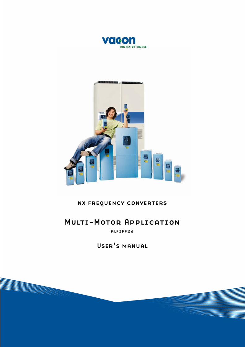
nx frequency converters
Multi-Motor Application
alfiff26
User’s manual
2 • vacon
Tel. +358 (0)201 2121 • Fax +358 (0)201 212 205
Vacon Multi-Motor Application (Software ALFIFF26) Ver. 1.02
INDEX
1. INTRODUCTION ....................................................................................................................3 2. CONTROL I/O......................................................................................................................4 3. MULTI-MOTOR APPLICATION – PARAMETER LISTS....................................................................5
3.1 Monitoring values (Control keypad: menu M1)........................................................... 5 3.2 Basic parameters (Control keypad: Menu P2 P2.1) ............................................... 6 3.3 Input signals (Control keypad: Menu P2 P2.2) ....................................................... 9 3.4 Output signals (Control keypad: Menu P2 P2.3)................................................... 11 3.5 Drive control parameters (Control keypad: Menu P2 P2.4)................................. 12 3.6 Prohibit frequency parameters (Control keypad: Menu P2 P2.5)........................ 12 3.7 Motor control parameters (Control keypad: Menu P2 P2.6)................................ 12 3.8 Protections (Control keypad: Menu P2 P2.7) ....................................................... 13 3.9 Autorestart parameters (Control keypad: Menu P2 P2.8) ................................... 13 3.10 Keypad control (Control keypad: Menu K3) .............................................................. 14 3.11 System menu (Control keypad: Menu S6)................................................................. 14 3.12 Expander boards (Control keypad: Menu E7) ........................................................... 14
4. DESCRIPTION OF PARAMETERS ............................................................................................15 4.1 BASIC PARAMETERS................................................................................................. 15 4.2 INPUT SIGNALS......................................................................................................... 20 4.3 OUTPUT SIGNALS...................................................................................................... 23 4.4 DRIVE CONTROL........................................................................................................ 26 4.5 PROHIBIT FREQUENCIES ......................................................................................... 29 4.6 MOTOR CONTROL...................................................................................................... 30 4.7 PROTECTIONS ........................................................................................................... 31 4.8 AUTO RESTART PARAMETERS ................................................................................. 38 4.9 KEYPAD CONTROL PARAMETERS............................................................................ 39
Introduction vacon • 3
24-hour support +358 (0)40 837 1150 • Email: [email protected] 1
Multicontrol Application 1. Introduction
The Multi-Motor Application for Vacon NXL is based on NXL Multi-Control Application. PID-control, PFC and motor potentiometer-feature are removed. The purpose of this application is to use two different parameter sets, which are selected using digital input. When the drive is commissioned, the only visible parameter group is P2.1 (Basic parameters). The special parameters can be browsed and edited after changing the value of par. 2.1.11 (Parameter conceal). The direct frequency reference can be selected from the analogue inputs, fieldbus, keypad or using preset speeds.
• Digital inputs DIN2, DIN3, (DIN4) and optional dig. inputs DIE1, DIE2, DIE3 are freely programmable.
• Internal and optional digital/relay and analogue outputs are freely programmable. • Analogue input 1 can be programmed as current input, voltage input or digital input DIN4. NOTE! If the analogue input 1 has been programmed as DIN4 with parameter 2.2.6 (AI1 Signal Range), check that the jumper selections (Error! Reference source not found.) are correct.
Additional functions:
• Programmable Start/Stop and Reverse signal logic • Reference scaling • 2 Preset speeds • Analogue input range selection, signal scaling, inversion and filtering • Frequency limit supervision • Programmable start and stop functions • DC-brake at start and stop • Prohibit frequency area • Programmable U/f curve and U/f optimisation • Adjustable switching frequency • Autorestart function after fault • Protections and supervisions (all fully programmable; off, warning, fault):
• Current input fault • External fault • Output phase • Under voltage • Earth fault
• Motor thermal, stall and underload protection • Thermistor • Fieldbus communication • Option board
4 • vacon Control I/O
Tel. +358 (0)201 2121 • Fax +358 (0)201 212 205
2
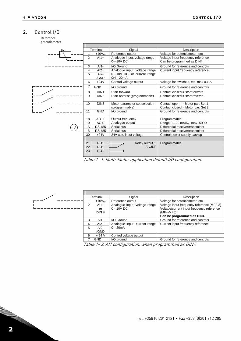
2. Control I/O
Terminal Signal Description 1 +10Vref Reference output Voltage for potentiometer, etc. 2 AI1+
Analogue input, voltage range 0—10V DC.
Voltage input frequency reference Can be programmed as DIN4
3 AI1- I/O Ground Ground for reference and controls 4 AI2+ 5 AI2-
/GND
Analogue input, voltage range 0—10V DC, or current range 0/4—20mA
Current input frequency reference
6 +24V Control voltage output Voltage for switches, etc. max 0.1 A 7 GND I/O ground Ground for reference and controls 8 DIN1 Start forward Contact closed = start forward 9 DIN2 Start reverse (programmable) Contact closed = start reverse
10 DIN3 Motor parameter set selection
(programmable) Contact open = Motor par. Set 1 Contact closed = Motor par. Set 2
11 GND
I/O ground Ground for reference and controls
18 AO1+ 19 AO1-
Output frequency Analogue output
Programmable Range 0—20 mA/RL, max. 500Ω
A RS 485 Serial bus Differential receiver/transmitter B RS 485 Serial bus Differential receiver/transmitter
30 +24V 24V aux. input voltage Control power supply backup 21 RO1 22 RO1 23 RO1
Relay output 1 FAULT
Programmable
Table 1- 1. Multi-Motor application default I/O configuration.
Terminal Signal Description
1 +10Vref Reference output Voltage for potentiometer, etc. 2 AI1+
or DIN 4
Analogue input, voltage range 0—10V DC
Voltage input frequency reference (MF2-3) Voltage/current input frequency reference (MF4-MF6) Can be programmed as DIN4
3 AI1- I/O Ground Ground for reference and controls 4 AI2+ 5 AI2-
/GND
Analogue input, current range 0—20mA
Current input frequency reference
6 + 24 V Control voltage output 7 GND I/O ground Ground for reference and controls
Table 1- 2. AI1 configuration, when programmed as DIN4
Reference potentiometer
mA
Multi-Motor Application – Parameter lists vacon • 5
24-hour support +358 (0)40 837 1150 • Email: [email protected] 3
3. Multi-Motor Application – Parameter lists
On the next pages you will find the lists of parameters within the respective parameter groups. The parameter descriptions are given on pages 15 to 38. Column explanations: Code = Location indication on the keypad; Shows the operator the present param. number Parameter = Name of parameter Min = Minimum value of parameter Max = Maximum value of parameter Unit = Unit of parameter value; Given if available Default = Value preset by factory Cust = Customer’s own setting ID = ID number of the parameter (used with PC tools) = On the parameter code: parameter value can only be changed after the FC has
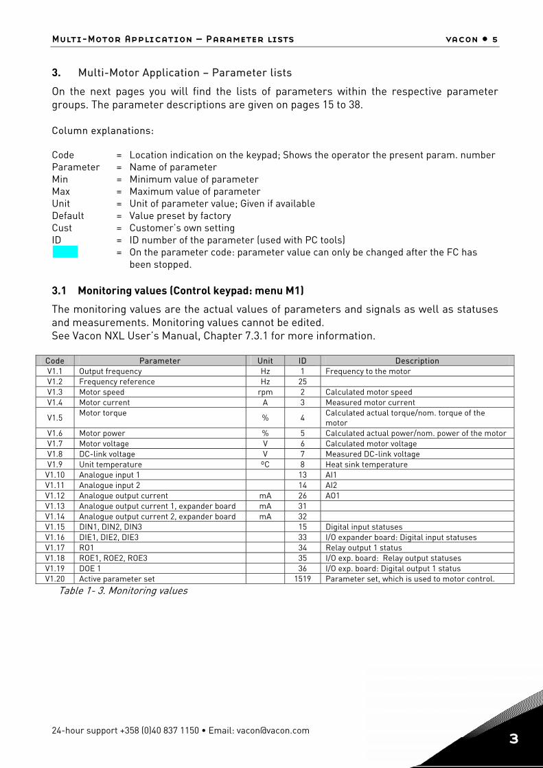
been stopped. 3.1 Monitoring values (Control keypad: menu M1)
The monitoring values are the actual values of parameters and signals as well as statuses and measurements. Monitoring values cannot be edited. See Vacon NXL User’s Manual, Chapter 7.3.1 for more information.
Code Parameter Unit ID Description V1.1 Output frequency Hz 1 Frequency to the motor V1.2 Frequency reference Hz 25 V1.3 Motor speed rpm 2 Calculated motor speed V1.4 Motor current A 3 Measured motor current
V1.5 Motor torque
% 4 Calculated actual torque/nom. torque of the motor
V1.6 Motor power % 5 Calculated actual power/nom. power of the motor V1.7 Motor voltage V 6 Calculated motor voltage V1.8 DC-link voltage V 7 Measured DC-link voltage V1.9 Unit temperature ºC 8 Heat sink temperature
V1.10 Analogue input 1 13 AI1 V1.11 Analogue input 2 14 AI2 V1.12 Analogue output current mA 26 AO1 V1.13 Analogue output current 1, expander board mA 31 V1.14 Analogue output current 2, expander board mA 32 V1.15 DIN1, DIN2, DIN3 15 Digital input statuses V1.16 DIE1, DIE2, DIE3 33 I/O expander board: Digital input statuses V1.17 RO1 34 Relay output 1 status V1.18 ROE1, ROE2, ROE3 35 I/O exp. board: Relay output statuses V1.19 DOE 1 36 I/O exp. board: Digital output 1 status V1.20 Active parameter set 1519 Parameter set, which is used to motor control.
Table 1- 3. Monitoring values
6 • vacon Multi-Motor Application – Parameter lists
Tel. +358 (0)201 2121 • Fax +358 (0)201 212 205
3
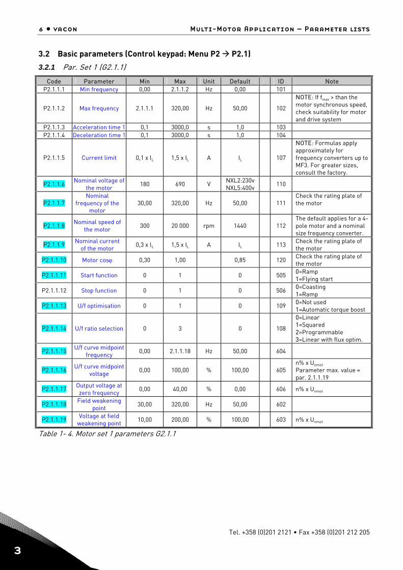
3.2 Basic parameters (Control keypad: Menu P2 P2.1)
3.2.1 Par. Set 1 (G2.1.1)
Code Parameter Min Max Unit Default ID Note P2.1.1.1 Min frequency 0,00 2.1.1.2 Hz 0,00 101
P2.1.1.2 Max frequency 2.1.1.1 320,00 Hz 50,00
102
NOTE: If fmax > than the motor synchronous speed, check suitability for motor and drive system
P2.1.1.3 Acceleration time 1 0,1 3000,0 s 1,0 103 P2.1.1.4 Deceleration time 1 0,1 3000,0 s 1,0 104
P2.1.1.5 Current limit 0,1 x IL 1,5 x IL A IL
107
NOTE: Formulas apply approximately for frequency converters up to MF3. For greater sizes, consult the factory.
P2.1.1.6 Nominal voltage of the motor
180 690 V NXL2:230v NXL5:400v
110
P2.1.1.7 Nominal
frequency of the motor
30,00 320,00 Hz 50,00
111 Check the rating plate of the motor
P2.1.1.8 Nominal speed of
the motor 300 20 000 rpm 1440
112
The default applies for a 4-pole motor and a nominal size frequency converter.
P2.1.1.9 Nominal current of the motor
0,3 x IL 1,5 x IL A IL 113 Check the rating plate of
the motor
P2.1.1.10 Motor cosϕ 0,30 1,00 0,85 120 Check the rating plate of the motor
P2.1.1.11 Start function 0 1 0 505 0=Ramp 1=Flying start
P2.1.1.12 Stop function 0 1 0 506 0=Coasting 1=Ramp
P2.1.1.13 U/f optimisation 0 1 0 109 0=Not used 1=Automatic torque boost
P2.1.1.14 U/f ratio selection 0 3 0
108
0=Linear 1=Squared 2=Programmable 3=Linear with flux optim.
P2.1.1.15 U/f curve midpoint frequency
0,00 2.1.1.18 Hz 50,00 604
P2.1.1.16 U/f curve midpoint
voltage 0,00 100,00 % 100,00
605 n% x Unmot
Parameter max. value = par. 2.1.1.19
P2.1.1.17 Output voltage at zero frequency
0,00 40,00 % 0,00 606 n% x Unmot
P2.1.1.18 Field weakening point
30,00 320,00 Hz 50,00 602
P2.1.1.19 Voltage at field weakening point
10,00 200,00 % 100,00 603 n% x Unmot
Table 1- 4. Motor set 1 parameters G2.1.1
Multi-Motor Application – Parameter lists vacon • 7
24-hour support +358 (0)40 837 1150 • Email: [email protected] 3
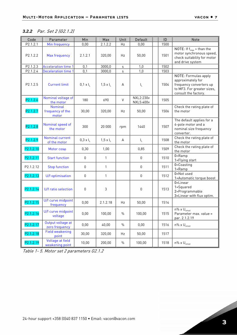
3.2.2 Par. Set 2 (G2.1.2)
Code Parameter Min Max Unit Default ID Note P2.1.2.1 Min frequency 0,00 2.1.2.2 Hz 0,00 1500
P2.1.2.2 Max frequency 2.1.2.1 320,00 Hz 50,00
1501
NOTE: If fmax > than the motor synchronous speed, check suitability for motor and drive system
P2.1.2.3 Acceleration time 1 0,1 3000,0 s 1,0 1502 P2.1.2.4 Deceleration time 1 0,1 3000,0 s 1,0 1503
P2.1.2.5 Current limit 0,1 x IL 1,5 x IL A IL
1504
NOTE: Formulas apply approximately for frequency converters up to MF3. For greater sizes, consult the factory.
P2.1.2.6 Nominal voltage of the motor
180 690 V NXL2:230v NXL5:400v
1505
P2.1.2.7 Nominal
frequency of the motor
30,00 320,00 Hz 50,00
1506 Check the rating plate of the motor
P2.1.2.8 Nominal speed of
the motor 300 20 000 rpm 1440
1507
The default applies for a 4-pole motor and a nominal size frequency converter.
P2.1.2.9 Nominal current of the motor
0,3 x IL 1,5 x IL A IL 1508 Check the rating plate of
the motor
P2.1.2.10 Motor cosϕ 0,30 1,00 0,85 1509 Check the rating plate of the motor
P2.1.2.11 Start function 0 1 0 1510 0=Ramp 1=Flying start
P2.1.2.12 Stop function 0 1 0 1511 0=Coasting 1=Ramp
P2.1.2.13 U/f optimisation 0 1 0 1512 0=Not used 1=Automatic torque boost
P2.1.2.14 U/f ratio selection 0 3 0
1513
0=Linear 1=Squared 2=Programmable 3=Linear with flux optim.
P2.1.2.15 U/f curve midpoint frequency
0,00 2.1.2.18 Hz 50,00 1514
P2.1.2.16 U/f curve midpoint
voltage 0,00 100,00 % 100,00
1515
n% x Unmot
Parameter max. value = par. 2.1.2.19
P2.1.2.17 Output voltage at zero frequency
0,00 40,00 % 0,00 1516 n% x Unmot
P2.1.2.18 Field weakening point
30,00 320,00 Hz 50,00 1517
P2.1.2.19 Voltage at field weakening point
10,00 200,00 % 100,00 1518 n% x Unmot
Table 1- 5. Motor set 2 parameters G2.1.2
8 • vacon Multi-Motor Application – Parameter lists
Tel. +358 (0)201 2121 • Fax +358 (0)201 212 205
3
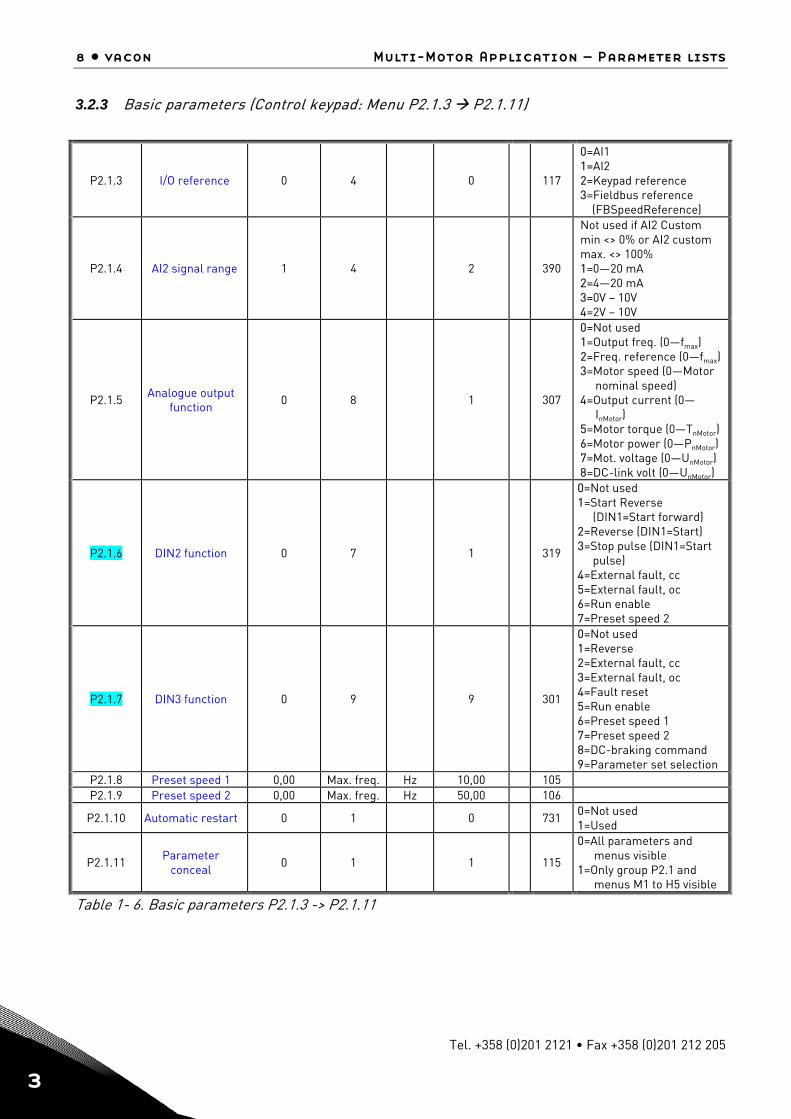
3.2.3 Basic parameters (Control keypad: Menu P2.1.3 P2.1.11)
P2.1.3 I/O reference 0 4 0
117
0=AI1 1=AI2 2=Keypad reference 3=Fieldbus reference (FBSpeedReference)
P2.1.4 AI2 signal range 1 4 2
390
Not used if AI2 Custom min <> 0% or AI2 custom max. <> 100% 1=0—20 mA 2=4—20 mA 3=0V – 10V 4=2V – 10V
P2.1.5 Analogue output
function 0 8 1
307
0=Not used 1=Output freq. (0—fmax) 2=Freq. reference (0—fmax) 3=Motor speed (0—Motor
nominal speed) 4=Output current (0—
InMotor) 5=Motor torque (0—TnMotor) 6=Motor power (0—PnMotor) 7=Mot. voltage (0—UnMotor) 8=DC-link volt (0—UnMotor)
P2.1.6 DIN2 function 0 7 1
319
0=Not used 1=Start Reverse
(DIN1=Start forward) 2=Reverse (DIN1=Start) 3=Stop pulse (DIN1=Start
pulse) 4=External fault, cc 5=External fault, oc 6=Run enable 7=Preset speed 2
P2.1.7 DIN3 function 0 9 9
301
0=Not used 1=Reverse 2=External fault, cc 3=External fault, oc 4=Fault reset 5=Run enable 6=Preset speed 1 7=Preset speed 2 8=DC-braking command 9=Parameter set selection
P2.1.8 Preset speed 1 0,00 Max. freq. Hz 10,00 105 P2.1.9 Preset speed 2 0,00 Max. freg. Hz 50,00 106
P2.1.10 Automatic restart 0 1 0
731 0=Not used 1=Used
P2.1.11 Parameter
conceal 0 1 1
115
0=All parameters and menus visible
1=Only group P2.1 and menus M1 to H5 visible
Table 1- 6. Basic parameters P2.1.3 -> P2.1.11
Multi-Motor Application – Parameter lists vacon • 9
24-hour support +358 (0)40 837 1150 • Email: [email protected] 3
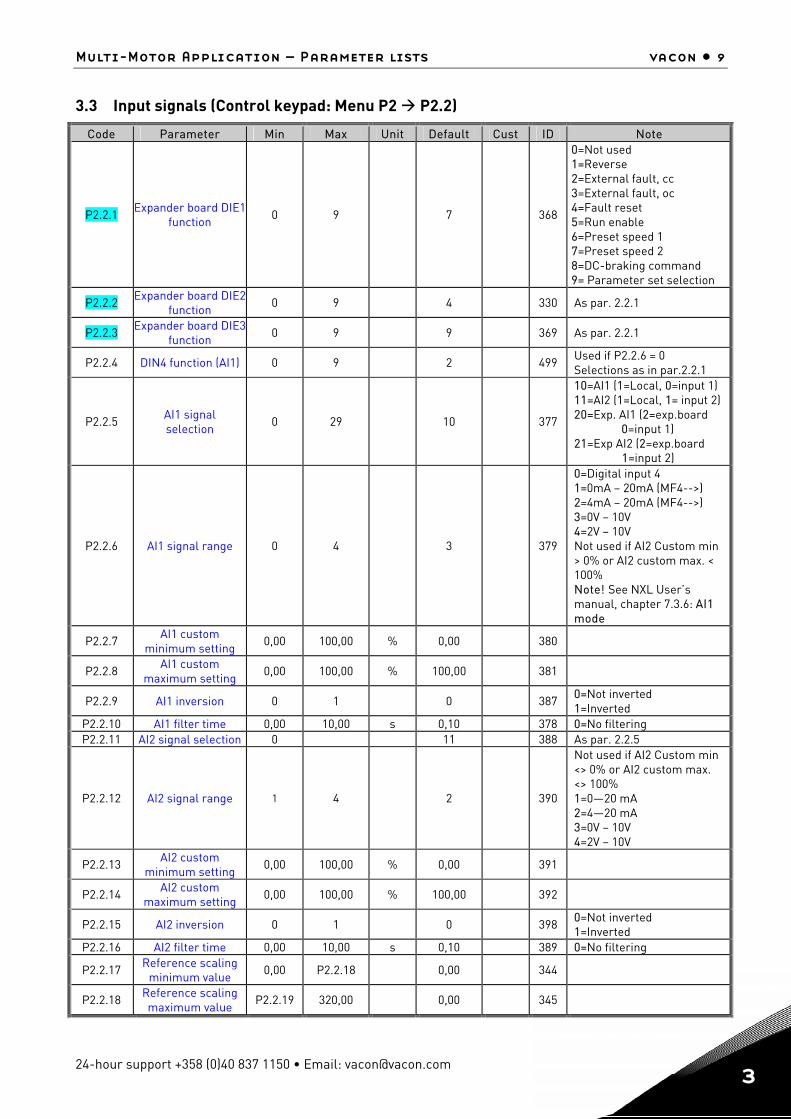
3.3 Input signals (Control keypad: Menu P2 P2.2)
Code Parameter Min Max Unit Default Cust ID Note
P2.2.1 Expander board DIE1
function 0 9 7
368
0=Not used 1=Reverse 2=External fault, cc 3=External fault, oc 4=Fault reset 5=Run enable 6=Preset speed 1 7=Preset speed 2 8=DC-braking command 9= Parameter set selection
P2.2.2 Expander board DIE2 function
0 9 4 330 As par. 2.2.1
P2.2.3 Expander board DIE3 function
0 9 9 369 As par. 2.2.1
P2.2.4 DIN4 function (AI1) 0 9 2 499 Used if P2.2.6 = 0 Selections as in par.2.2.1
P2.2.5 AI1 signal selection
0 29 10
377
10=AI1 (1=Local, 0=input 1) 11=AI2 (1=Local, 1= input 2) 20=Exp. AI1 (2=exp.board
0=input 1) 21=Exp AI2 (2=exp.board
1=input 2)
P2.2.6 AI1 signal range 0 4 3
379
0=Digital input 4 1=0mA – 20mA (MF4-->) 2=4mA – 20mA (MF4-->) 3=0V – 10V 4=2V – 10V Not used if AI2 Custom min > 0% or AI2 custom max. < 100% Note! See NXL User’s manual, chapter 7.3.6: AI1 mode
P2.2.7 AI1 custom minimum setting
0,00 100,00 % 0,00 380
P2.2.8 AI1 custom maximum setting
0,00 100,00 % 100,00 381
P2.2.9 AI1 inversion 0 1 0 387 0=Not inverted 1=Inverted
P2.2.10 AI1 filter time 0,00 10,00 s 0,10 378 0=No filtering P2.2.11 AI2 signal selection 0 11 388 As par. 2.2.5
P2.2.12 AI2 signal range 1 4 2
390
Not used if AI2 Custom min <> 0% or AI2 custom max. <> 100% 1=0—20 mA 2=4—20 mA 3=0V – 10V 4=2V – 10V
P2.2.13 AI2 custom minimum setting
0,00 100,00 % 0,00 391
P2.2.14 AI2 custom maximum setting
0,00 100,00 % 100,00 392
P2.2.15 AI2 inversion 0 1 0 398 0=Not inverted 1=Inverted
P2.2.16 AI2 filter time 0,00 10,00 s 0,10 389 0=No filtering
P2.2.17 Reference scaling minimum value
0,00 P2.2.18 0,00 344
P2.2.18 Reference scaling maximum value
P2.2.19 320,00 0,00 345
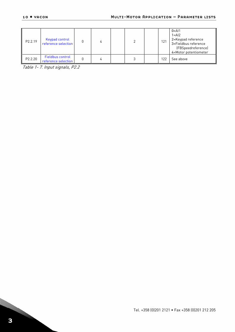
10 • vacon Multi-Motor Application – Parameter lists
Tel. +358 (0)201 2121 • Fax +358 (0)201 212 205
3
P2.2.19 Keypad control reference selection
0 4 2
121
0=AI1 1=AI2 2=Keypad reference 3=Fieldbus reference
(FBSpeedreference) 4=Motor potentiometer
P2.2.20 Fieldbus control reference selection
0 4 3 122 See above
Table 1- 7. Input signals, P2.2
Multi-Motor Application – Parameter lists vacon • 11
24-hour support +358 (0)40 837 1150 • Email: [email protected] 3
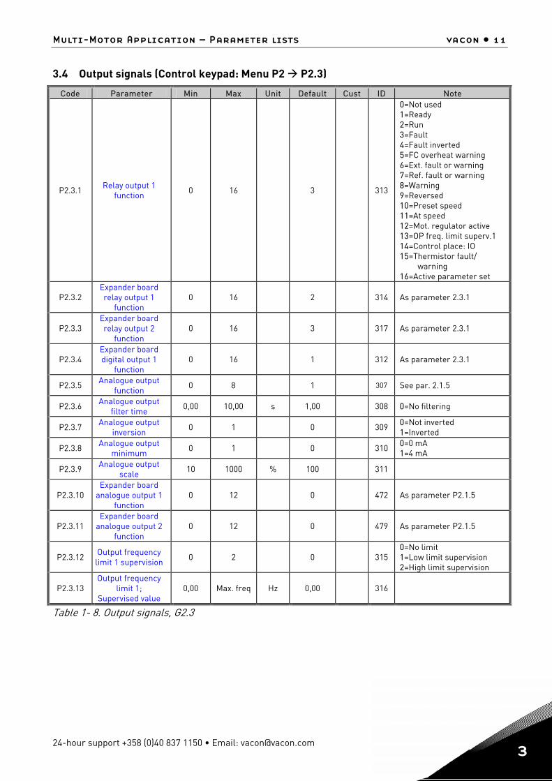
3.4 Output signals (Control keypad: Menu P2 P2.3)
Code Parameter Min Max Unit Default Cust ID Note
P2.3.1 Relay output 1 function
0 16 3
313
0=Not used 1=Ready 2=Run 3=Fault 4=Fault inverted 5=FC overheat warning 6=Ext. fault or warning 7=Ref. fault or warning 8=Warning 9=Reversed 10=Preset speed 11=At speed 12=Mot. regulator active 13=OP freq. limit superv.1 14=Control place: IO 15=Thermistor fault/
warning 16=Active parameter set
P2.3.2 Expander board relay output 1
function 0 16 2
314 As parameter 2.3.1
P2.3.3 Expander board relay output 2
function 0 16 3
317 As parameter 2.3.1
P2.3.4 Expander board digital output 1
function 0 16 1
312 As parameter 2.3.1
P2.3.5 Analogue output function
0 8 1
307 See par. 2.1.5
P2.3.6 Analogue output filter time
0,00 10,00 s 1,00 308 0=No filtering
P2.3.7 Analogue output inversion
0 1 0 309 0=Not inverted 1=Inverted
P2.3.8 Analogue output minimum
0 1 0 310 0=0 mA 1=4 mA
P2.3.9 Analogue output scale
10 1000 % 100 311
P2.3.10 Expander board
analogue output 1 function
0 12 0 472 As parameter P2.1.5
P2.3.11 Expander board
analogue output 2 function
0 12 0
479 As parameter P2.1.5
P2.3.12 Output frequency
limit 1 supervision 0 2 0
315
0=No limit 1=Low limit supervision 2=High limit supervision
P2.3.13 Output frequency
limit 1; Supervised value
0,00 Max. freq Hz 0,00
316
Table 1- 8. Output signals, G2.3
12 • vacon Multi-Motor Application – Parameter lists
Tel. +358 (0)201 2121 • Fax +358 (0)201 212 205
3
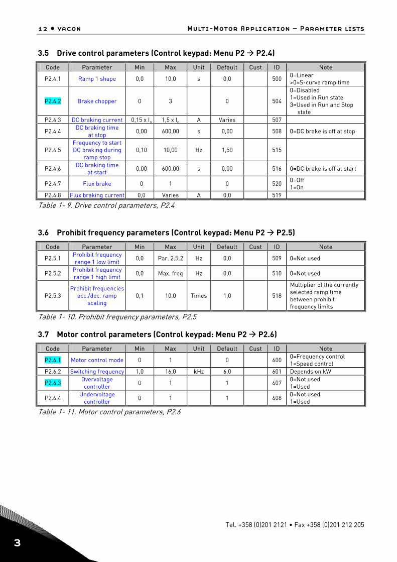
3.5 Drive control parameters (Control keypad: Menu P2 P2.4)
Code Parameter Min Max Unit Default Cust ID Note
P2.4.1 Ramp 1 shape 0,0 10,0 s 0,0 500 0=Linear >0=S-curve ramp time
P2.4.2 Brake chopper 0 3 0
504
0=Disabled 1=Used in Run state 3=Used in Run and Stop
state P2.4.3 DC braking current 0,15 x In 1,5 x In A Varies 507
P2.4.4 DC braking time at stop
0,00 600,00 s 0,00 508 0=DC brake is off at stop
P2.4.5 Frequency to start DC braking during
ramp stop 0,10 10,00 Hz 1,50
515
P2.4.6 DC braking time at start
0,00 600,00 s 0,00 516 0=DC brake is off at start
P2.4.7 Flux brake 0 1 0 520 0=Off 1=On
P2.4.8 Flux braking current 0,0 Varies A 0,0 519
Table 1- 9. Drive control parameters, P2.4
3.6 Prohibit frequency parameters (Control keypad: Menu P2 P2.5)
Code Parameter Min Max Unit Default Cust ID Note
P2.5.1 Prohibit frequency range 1 low limit
0,0 Par. 2.5.2 Hz 0,0 509 0=Not used
P2.5.2 Prohibit frequency range 1 high limit
0,0 Max. freq Hz 0,0 510 0=Not used
P2.5.3 Prohibit frequencies
acc./dec. ramp scaling
0,1 10,0 Times 1,0
518
Multiplier of the currently selected ramp time between prohibit frequency limits
Table 1- 10. Prohibit frequency parameters, P2.5
3.7 Motor control parameters (Control keypad: Menu P2 P2.6)
Code Parameter Min Max Unit Default Cust ID Note
P2.6.1 Motor control mode 0 1 0 600 0=Frequency control 1=Speed control
P2.6.2 Switching frequency 1,0 16,0 kHz 6,0 601 Depends on kW
P2.6.3 Overvoltage controller
0 1 1 607 0=Not used 1=Used
P2.6.4 Undervoltage controller
0 1 1 608 0=Not used 1=Used
Table 1- 11. Motor control parameters, P2.6
Multi-Motor Application – Parameter lists vacon • 13
24-hour support +358 (0)40 837 1150 • Email: [email protected] 3
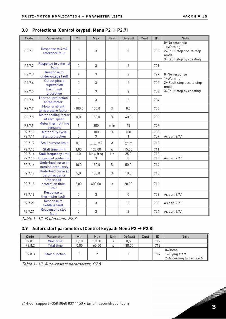
3.8 Protections (Control keypad: Menu P2 P2.7)
Code Parameter Min Max Unit Default Cust ID Note
P2.7.1 Response to 4mA
reference fault 0 3 0
700
0=No response 1=Warning 2=Fault,stop acc. to stop mode 3=Fault,stop by coasting
P2.7.2 Response to externalfault
0 3 2 701
P2.7.3 Response to undervoltage fault
1 3 2 727
P2.7.4 Output phase supervision
0 3 2 702
P2.7.5 Earth fault protection
0 3 2 703
P2.7.6 Thermal protection of the motor
0 3 2 704
0=No response 1=Warning 2= Fault,stop acc. to stop mode 3=Fault,stop by coasting
P2.7.7 Motor ambient temperature factor
–100,0 100,0 % 0,0 705
P2.7.8 Motor cooling factor at zero speed
0,0 150,0 % 40,0 706
P2.7.9 Motor thermal time constant
1 200 min 45 707
P2.7.10 Motor duty cycle 0 100 % 100 708 P2.7.11 Stall protection 0 3 1 709 As par. 2.7.1
P2.7.12 Stall current limit 0,1 Inmotor x 2 A Inmotor x1.3
710
P2.7.13 Stall time limit 1,00 120,00 s 15,00 711 P2.7.14 Stall frequency limit 1,0 Max. freq Hz 25,0 712 P2.7.15 Underload protection 0 3 0 713 As par. 2.7.1
P2.7.16 Underload curve at nominal frequency
10,0 150,0 % 50,0 714
P2.7.17 Underload curve at zero frequency
5,0 150,0 % 10,0 715
P2.7.18 Underload
protection time limit
2,00 600,00 s 20,00
716
P2.7.19 Response to thermistor fault
0 3 0 732 As par. 2.7.1
P2.7.20 Response to fieldbus fault
0 3 2 733 As par. 2.7.1
P2.7.21 Response to slot fault
0 3 2 734 As par. 2.7.1
Table 1- 12. Protections, P2.7
3.9 Autorestart parameters (Control keypad: Menu P2 P2.8)
Code Parameter Min Max Unit Default Cust ID Note P2.8.1 Wait time 0,10 10,00 s 0,50 717 P2.8.2 Trial time 0,00 60,00 s 30,00 718
P2.8.3 Start function 0 2 0
719 0=Ramp 1=Flying start 2=According to par. 2.4.6
Table 1- 13. Auto-restart parameters, P2.8
14 • vacon Multi-Motor Application – Parameter lists
Tel. +358 (0)201 2121 • Fax +358 (0)201 212 205
3
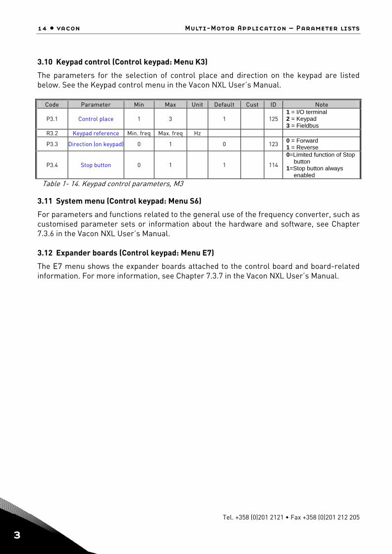
3.10 Keypad control (Control keypad: Menu K3)
The parameters for the selection of control place and direction on the keypad are listed below. See the Keypad control menu in the Vacon NXL User’s Manual.
Code Parameter Min Max Unit Default Cust ID Note
P3.1 Control place 1 3 1
125 1 = I/O terminal 2 = Keypad 3 = Fieldbus
R3.2 Keypad reference Min. freq Max. freq Hz
P3.3 Direction (on keypad) 0 1 0 123 0 = Forward 1 = Reverse
P3.4 Stop button 0 1 1
114
0=Limited function of Stop button
1=Stop button always enabled
Table 1- 14. Keypad control parameters, M3
3.11 System menu (Control keypad: Menu S6)
For parameters and functions related to the general use of the frequency converter, such as customised parameter sets or information about the hardware and software, see Chapter 7.3.6 in the Vacon NXL User’s Manual. 3.12 Expander boards (Control keypad: Menu E7)
The E7 menu shows the expander boards attached to the control board and board-related information. For more information, see Chapter 7.3.7 in the Vacon NXL User’s Manual.
Description of parameters vacon • 15
24-hour support +358 (0)40 837 1150 • Email: [email protected] 4
4. Description of parameters
4.1 BASIC PARAMETERS
2.1.1.1, 2.1.2.1, 2.1.1.2, 2.1.2.2 Minimum/maximum frequency
Defines the frequency limits of the frequency converter. The maximum value for these parameters is 320 Hz.
2.1.1.3, 2.1.2.3, 2.1.1.4, 2.1.2.4 Acceleration time 1, deceleration time 1
These limits correspond to the time required for the output frequency to accelerate from the zero frequency to the set maximum frequency.
2.1.1.5, 2.1.2.5 Current limit
This parameter determines the maximum motor current from the frequency converter. To avoid motor overload, set this parameter according to the rated current of the motor. The current limit is equal to the rated converter current (IL) by default.
2.1.1.6, 2.1.2.6 Nominal voltage of the motor
Find this value Un on the rating plate of the motor. This parameter sets the voltage at the field weakening point to 100% x Unmotor.
2.1.1.7, 2.1.2.7 Nominal frequency of the motor
Find this value fn on the rating plate of the motor. This parameter sets the field weakening point to the same value.
2.1.1.8, 2.1.2.8 Nominal speed of the motor
Find this value nn on the rating plate of the motor.
2.1.1.9, 2.1.2.9 Nominal current of the motor
Find this value In on the rating plate of the motor.
2.1.1.10, 2.1.2.10 Motor cos phi
Find this value “cos phi” on the rating plate of the motor.
2.1.1.11, 2.1.2.11 Start function
Ramp: 0 The frequency converter starts from 0 Hz and accelerates to maximum
frequency within the set acceleration time. (Load inertia or starting friction may cause prolonged acceleration times).
Flying start: 1 The frequency converter is able to start into a running motor by applying a
small torque to motor and searching for the frequency corresponding to the speed the motor is running at. The searching starts from the maximum frequency towards the actual frequency until the correct value is detected.
16 • vacon Description of parameters
Tel. +358 (0)201 2121 • Fax +358 (0)201 212 205
4
Thereafter, the output frequency will be increased/decreased to the set reference value according to the set acceleration/deceleration parameters. Use this mode if the motor is coasting when the start command is given. With the flying start, it is possible to ride through short mains voltage interruptions.
2.1.1.12, 2.1.2.12 Stop function
Coasting: 0 The motor coasts to a halt without control from the frequency converter after
the Stop command.
Ramp: 1 After the Stop command, the speed of the motor is decelerated according to
the set deceleration parameters. If the regenerated energy is high it may be necessary to use an external braking resistor for faster deceleration.
2.1.1.13, 2.1.2.13 U/f optimisation
0 Not used 1 Automatic torque boost
The voltage to the motor changes automatically, which makes the motor produce sufficient torque to start and run at low frequencies. The voltage increase depends on the motor type and power. Automatic torque boost can be used in applications where starting torque due to starting friction is high, e.g. in conveyors.
NOTE! In high torque – low speed applications – it is likely that the motor
will overheat. If the motor has to run a prolonged time under these conditions, special attention must be paid to cooling the motor. Use external cooling for the motor if the temperature tends to rise too high.
2.1.1.14, 2.1.2.14 U/f ratio selection
Linear: The voltage of the motor changes linearly with the frequency in the constant 0 flux area from 0 Hz to the field weakening point where the nominal voltage is
supplied to the motor. Linear U/f ratio should be used in constant torque applications.
This default setting should be used if there is no special need for another setting.
Squared: The voltage of the motor changes following a squared curve form 1 with the frequency in the area from 0 Hz to the field weakening point where
the nominal voltage is also supplied to the motor. The motor runs under magnetised below the field weakening point and produces less torque and electromechanical noise. Squared U/f ratio can be used in applications where torque demand of the load is proportional to the square of the speed, e.g in centrifugal fans and pumps.
vacon Multi-Motor Application Page 17
24-hour support +358 (0)40 837 1150 • Email: [email protected]
1
4
Programmable U/f curve: 2 The U/f curve can be programmed with three different points. Programmable
U/f curve can be used if the other settings do not satisfy the needs of the application.
Linear with flux optimisation: 3 The frequency converter starts to search for the minimum motor
current and in order to save energy, lower the disturbance level and the noise. Can be used in applications with constant motor load, such as fans, pumps etc.
2.1.1.15, 2.1.2.15 U/f curve, middle point frequency
If the programmable U/f curve has been selected, this parameter defines the middle point frequency of the curve.
2.1.1.16, 2.1.2.16 U/f curve, middle point voltage
If the programmable U/f curve has been selected, this parameter defines the middle point voltage of the curve.
2.1.1.17, 2.1.2.17 Output voltage at zero frequency
This parameter defines the zero frequency voltage of the curve.
2.1.1.18, 2.1.2.18 Field weakening point
The field weakening point is the output frequency at which the output voltage reaches the value set with parameter 2.1.1.19/2.1.2.19.
2.1.1.19, 2.1.2.19 Voltage at field weakening point
Above the frequency at the field weakening point, the output voltage remains at the value set with this parameter. Below the frequency at the field weakening point, the output voltage depends on the setting of the U/f curve parameters. When the motor nominal voltage and nominal frequency are set, the FWP and voltage at FWP are automatically given the corresponding values. If you need different values for the field weakening point and the voltage, change these parameters after setting the nominal voltage and frequency parameters.
2.1.3 I/O Reference selection
Defines the selected frequency reference source when the drive is controlled from the I/O terminal. 0 AI1 reference (terminals 2 and 3, e.g. potentiometer) 1 AI2 reference (terminals 5 and 6, e.g. transducer) 2 Keypad reference (parameter 3.2) 3 Reference from Fieldbus (FBSpeedReference)
Page 18 Multi-Motor Application vacon
Tel. +358 (0)201 2121 • Fax +358 (0)201 212 205
1
4
2.1.4 AI2 (Iin) signal range
1 Signal range 0…20 mA 2 Signal range 4…20 mA 3 Signal range 0...10V 4 Signal range 2...10V
Note! The selections have no effect if par. 2.2.13 > 0%, or par. 2.2.14 < 100%.
2.1.5 Analogue output function
This parameter selects the desired function for the analogue output signal. See the table on page 7 for the parameter values.
2.1.6 DIN2 function
This parameter has 7 selections. If digital input DIN2 need not be used, set the parameter value to 0.
1 Start reverse 2 Reverse 3 Stop pulse 4 External fault Contact closed: Fault is displayed and motor stopped when the input is active 5 External fault Contact open: Fault is displayed and motor stopped when the input is not active 6 Run enable Contact open: Start of motor disabled Contact closed: Start of motor enabled Coast stop if dropped during RUN 7 Preset speed 2
2.1.7 DIN3 function
This parameter has 9 selections. If digital input DIN3 need not be used, set the param. value to 0.
1 Reverse Contact open: Forward Contact closed: Reverse
2 External fault Contact closed: Fault is displayed and motor stopped when the input is active
3 External fault Contact open: Fault is displayed and motor stopped when the input is not active 4 Fault reset Contact closed: All faults reset 5 Run enable Contact open: Start of motor disabled Contact closed: Start of motor enabled
Coast stop if dropped during RUN
vacon Multi-Motor Application Page 19
24-hour support +358 (0)40 837 1150 • Email: [email protected]
1
4
6 Preset speed 1 7 Preset speed 2 8 DC braking command Contact closed: In Stop mode, the DC braking operates until the contact is opened.
DC-braking current is about 10% of the value selected with par. 2.4.3. 9 Parameter set selection
Contact open: Parameter set 1 is active (Parameter group G2.1.1) Contact close: Parameter set 2 is active (Parameter group G2.1.2)
2.1.8 Preset speed 1 2.1.9 Preset speed 2
Parameter values are automatically limited between the minimum and maximum frequencies.
2.1.10 Automatic restart function
The automatic restart is taken into use with this parameter 0 = Disabled 1 = Enabled (3 automatic restarts, see par. 2.8.1 – 2.8.3)
2.1.11 Parameter conceal
With this parameter you can hide all other parameter groups except the basic parameter group (P2.1). Note! The factory default of this parameter is 1, i.e. all parameter groups except P2.1 have been hidden. The other parameter groups cannot be browsed or edited before the value of this parameter is set to 0. 0 = Disabled (all parameter groups can be browsed with the keypad) 1 = Enabled (only the basic parameters, P2.1, can be browsed with the keypad)
Page 20 Multi-Motor Application vacon
Tel. +358 (0)201 2121 • Fax +358 (0)201 212 205
1
4
4.2 INPUT SIGNALS
2.2.1 Expander board DIE1 function
This parameter has 9 selections. If the expander board digital input DIN1 need not be used, set the parameter value to 0. Selections are as in parameter 2.1.7
2.2.2 Expander board DIE2 function
The selections are the same as in parameter 2.1.7
2.2.3 Expander board DIE3 function
The selections are the same as in parameter 2.1.7.
2.2.4 DIN4 Function
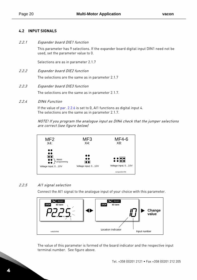
If the value of par. 2.2.6 is set to 0, AI1 functions as digital input 4. The selections are the same as in parameter 2.1.7. NOTE! If you program the analogue input as DIN4 check that the jumper selections are correct (see figure below)
2.2.5 AI1 signal selection
Connect the AI1 signal to the analogue input of your choice with this parameter.
The value of this parameter is formed of the board indicator and the respective input terminal number. See figure above.
STOP I/O termREADY
STOP I/O termREADY
nxlk29.fh8
Changevalue
Input numberLocation indicator
MF2 X4:
MF3 X4:
Jumperdin4.fh8
MF4-6 X8:
Voltage input; 0...10V Voltage input; 0...10V
RS485programming
Voltage input; 0...10V
vacon Multi-Motor Application Page 21
24-hour support +358 (0)40 837 1150 • Email: [email protected]
1
4
%
100%
63%
Par. 2.2.10
t [s]
N X 1 2K78
Fi l t e r e d s i g n a l
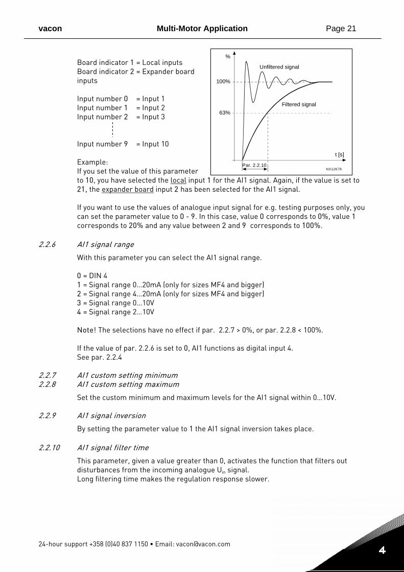
Unfiltered s i g n a l Board indicator 1 = Local inputs Board indicator 2 = Expander board inputs Input number 0 = Input 1 Input number 1 = Input 2 Input number 2 = Input 3 Input number 9 = Input 10
Example: If you set the value of this parameter to 10, you have selected the local input 1 for the AI1 signal. Again, if the value is set to 21, the expander board input 2 has been selected for the AI1 signal. If you want to use the values of analogue input signal for e.g. testing purposes only, you can set the parameter value to 0 - 9. In this case, value 0 corresponds to 0%, value 1 corresponds to 20% and any value between 2 and 9 corresponds to 100%.
2.2.6 AI1 signal range
With this parameter you can select the AI1 signal range. 0 = DIN 4 1 = Signal range 0…20mA (only for sizes MF4 and bigger) 2 = Signal range 4…20mA (only for sizes MF4 and bigger) 3 = Signal range 0…10V 4 = Signal range 2…10V Note! The selections have no effect if par. 2.2.7 > 0%, or par. 2.2.8 < 100%. If the value of par. 2.2.6 is set to 0, AI1 functions as digital input 4. See par. 2.2.4
2.2.7 AI1 custom setting minimum 2.2.8 AI1 custom setting maximum
Set the custom minimum and maximum levels for the AI1 signal within 0…10V.
2.2.9 AI1 signal inversion
By setting the parameter value to 1 the AI1 signal inversion takes place. 2.2.10 AI1 signal filter time
This parameter, given a value greater than 0, activates the function that filters out disturbances from the incoming analogue Uin signal. Long filtering time makes the regulation response slower.
Page 22 Multi-Motor Application vacon
Tel. +358 (0)201 2121 • Fax +358 (0)201 212 205
1
4
2.2.11 AI2 signal selection
Connect the AI2 signal to the analogue input of your choice with this parameter. See par. 2.2.5 for the value setting procedure.
2.2.12 AI2 signal range
1 = Signal range 0…20mA 2 = Signal range 4…20mA 3 = Signal range 0…10V 4 = Signal range 2…10V Note! The selections have no effect if par. 2.2.13 > 0%, or par.2.2.14 < 100%.
2.2.13 AI2 custom minimum 2.2.14 AI2 custom maximum
These parameters allow you to scale the input current signal between 0 and 20 mA.
2.2.15 Analogue input AI2 signal inversion
By setting the parameter value to 1 the AI2 signal inversion takes place.
2.2.16 Analogue input AI2 signal filter time
See corresponding parameter 2.2.10.
2.2.17 Reference scaling minimum value 2.2.18 Reference scaling maximum value
You can choose a scaling range for the frequency reference between the Minimum and Maximum frequency. If no scaling is desired set the parameter value to 0. In the figures below, voltage input AI1 with signal range 0…10V is selected for reference.
2.2.19 Keypad frequency reference selection
Defines the selected reference source when the drive is controlled from the keypad 0 AI1 reference (by default AI1, terminals 2 and 3, e.g. potentiometer) 1 AI2 reference (by default AI2, terminals 5 and 6, e.g. transducer) 2 Keypad reference (parameter 3.2) 3 Reference from Fieldbus (FBSpeedReference)
2.2.20 Fieldbus frequency reference selection
Defines the selected reference source when the drive is controlled from the fieldbus. Same selections as 2.2.19 above.

vacon Multi-Motor Application Page 23
24-hour support +358 (0)40 837 1150 • Email: [email protected]
1
4
4.3 OUTPUT SIGNALS
2.3.1 Relay output 1 function 2.3.2 Expander board relay output 1 function 2.3.3 Expander board relay output 2 function 2.3.4 Expander board digital output 1 function
Setting value Signal content
0 = Not used Out of operation
Relay output RO1 and expander board programmable relays (RO1, RO2) are activated when:
1 = Ready The frequency converter is ready to operate
2 = Run The frequency converter operates (motor is running)
3 = Fault A fault trip has occurred
4 = Fault inverted A fault trip not occurred 5 = Frequency converter overheat
warning The heat-sink temperature exceeds +70°C
6 = External fault or warning Fault or warning depending on par. 2.7.2
7 = Reference fault or warning Fault or warning depending on par. 2.7.1 - if analogue reference is 4—20 mA and signal is <4mA
8 = Warning Always if a warning exists
9 = Reversed The reverse command has been selected
10 = Preset speed A preset speed has been selected
11 = At speed The output frequency has reached the set reference
12 = Motor regulator activated Overvoltage or overcurrent regulator was activated
13 = Output frequency limit 1 supervision
The output frequency goes outside the set supervision low limit/high limit (see parameters 2.3.12 and 2.3.13 below)
14 = Control from I/O terminals Selected control place (Menu K3; par. 3.1) is “I/O terminal”
15 = Thermistor fault or warning The thermistor input of option board indicates overtemperature. Fault or warning depending on parameter 2.7.19.
16 = Active parameter set indication Open contactor=Set 1, closed contactor=Set2
Table 1- 15. Output signals via RO1 and expander board RO1, RO2 and DO1.
2.3.5 Analogue output function
This parameter selects the desired function for the analogue output signal. See the table on page 7 for the parameter values.
Page 24 Multi-Motor Application vacon
Tel. +358 (0)201 2121 • Fax +358 (0)201 212 205
1
4
%
t [s]
NX12K16
Filtered signal
Unfiltered signal
Par. 2.3.6
1.00
20 mA
4 mA
10 mA
0.50 mA
12 mA
NX12K17
Param. 2.3.9= 200%
Param. 2.3.9= 100%
Param. 2.3.9= 50%
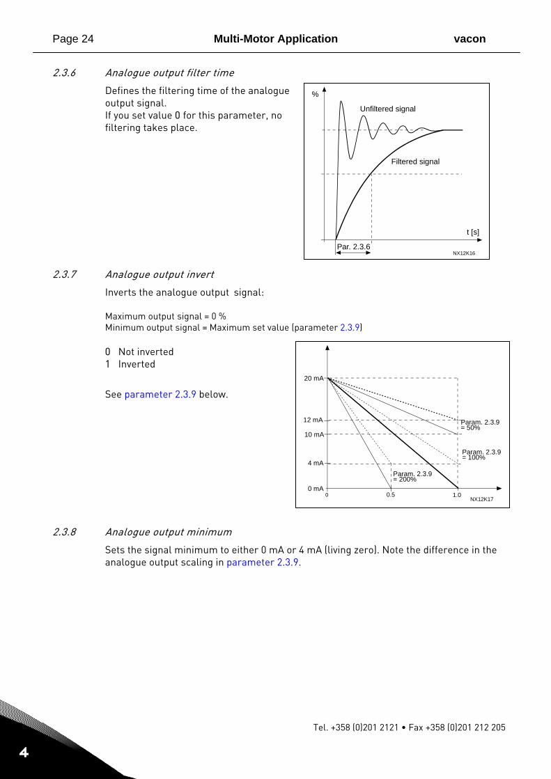
2.3.6 Analogue output filter time
Defines the filtering time of the analogue output signal. If you set value 0 for this parameter, no filtering takes place.
2.3.7 Analogue output invert
Inverts the analogue output signal: Maximum output signal = 0 % Minimum output signal = Maximum set value (parameter 2.3.9) 0 Not inverted 1 Inverted
See parameter 2.3.9 below.
2.3.8 Analogue output minimum
Sets the signal minimum to either 0 mA or 4 mA (living zero). Note the difference in the analogue output scaling in parameter 2.3.9.
vacon Multi-Motor Application Page 25
24-hour support +358 (0)40 837 1150 • Email: [email protected]
1
4
1.00
20 mA
4 mA
10 mA
0.50 mA
nxlk49.fh8
12 mA
Par. 2.3.8 = 1
Par. 2.3.8 = 0
Par. 2.3.9=200% Par. 2.3.9=
100%
Par. 2.3.9=50%
Analogueoutputcurrent
Max. value of signalselected by param. 2.1.16
2.3.9 Analogue output scale
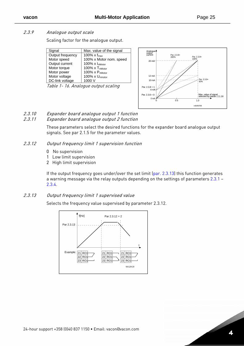
Scaling factor for the analogue output.
Signal Max. value of the signal Output frequency 100% x fmax Motor speed 100% x Motor nom. speed Output current 100% x InMotor Motor torque 100% x TnMotor Motor power 100% x PnMotor Motor voltage 100% x Unmotor DC-link voltage 1000 V
Table 1- 16. Analogue output scaling
2.3.10 Expander board analogue output 1 function 2.3.11 Expander board analogue output 2 function
These parameters select the desired functions for the expander board analogue output signals. See par 2.1.5 for the parameter values.
2.3.12 Output frequency limit 1 supervision function
0 No supervision 1 Low limit supervision 2 High limit supervision If the output frequency goes under/over the set limit (par. 2.3.13) this function generates a warning message via the relay outputs depending on the settings of parameters 2.3.1 – 2.3.4.
2.3.13 Output frequency limit 1 supervised value
Selects the frequency value supervised by parameter 2.3.12.
f[Hz]
t
21 RO122 RO123 RO1
21 RO122 RO123 RO1
21 RO122 RO123 RO1
NX12K19
Example:
Par 2.3.13
Par 2.3.12 = 2
Page 26 Multi-Motor Application vacon
Tel. +358 (0)201 2121 • Fax +358 (0)201 212 205
1
4
4.4 DRIVE CONTROL
2.4.1 Acceleration/Deceleration ramp 1 shape
The start and end of the acceleration and deceleration ramp can be smoothed with this parameter. Setting value 0 gives a linear ramp shape, which causes acceleration and deceleration to act immediately to the changes in the reference signal. Setting value 0.1…10 seconds for this parameter produces an S-shaped acceleration/deceleration.
2.4.2 Brake chopper
Note! An internal brake chopper is installed in all other sizes but MF2 0 No brake chopper used 1 Brake chopper used in Run state 3 Used in Run and Stop state When the frequency converter is decelerating the motor, the inertia of the motor and the load are fed into an external brake resistor. This enables the frequency converter to decelerate the load with a torque equal to that of acceleration (provided that the correct brake resistor has been selected). See separate Brake resistor installation manual.
2.4.3 DC-braking current
Defines the current injected into the motor during DC-braking.
2.4.4 DC-braking time at stop
Determines if braking is ON or OFF and the braking time of the DC-brake when the motor is stopping. The function of the DC-brake depends on the stop function. 0 DC-brake is not used >0 DC-brake is in use and its function depends on the Stop function. The DC-
braking time is determined with this parameter
vacon Multi-Motor Application Page 27
24-hour support +358 (0)40 837 1150 • Email: [email protected]
1
4
t = Par. 2.4.4
t
par. 2.4.5
NX12K23
Motor speed
Output frequency
DC-braking
RUNSTOP
fout
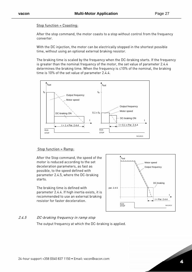
Stop function = Coasting: After the stop command, the motor coasts to a stop without control from the frequency converter. With the DC injection, the motor can be electrically stopped in the shortest possible time, without using an optional external braking resistor. The braking time is scaled by the frequency when the DC-braking starts. If the frequency is greater than the nominal frequency of the motor, the set value of parameter 2.4.4 determines the braking time. When the frequency is ≤10% of the nominal, the braking time is 10% of the set value of parameter 2.4.4.
Stop function = Ramp: After the Stop command, the speed of the motor is reduced according to the set deceleration parameters, as fast as possible, to the speed defined with parameter 2.4.5, where the DC-braking starts. The braking time is defined with parameter 2.4.4. If high inertia exists, it is recommended to use an external braking resistor for faster deceleration.
2.4.5 DC-braking frequency in ramp stop
The output frequency at which the DC-braking is applied.
fn fn
t t
t = 1 x Par. 2.4.4 t = 0,1 x Par. 2.4.4
NX12K21
0,1 x fn
RUNSTOP
RUNSTOP
Output frequency
Motor speed
Output frequency
Motor speed
DC-braking ON
DC-braking ON
fout fout
Page 28 Multi-Motor Application vacon
Tel. +358 (0)201 2121 • Fax +358 (0)201 212 205
1
4
t
NX12K80
Par 2.4.6
RUNSTOP
Outputfrequency
2.4.6 DC-braking time at start
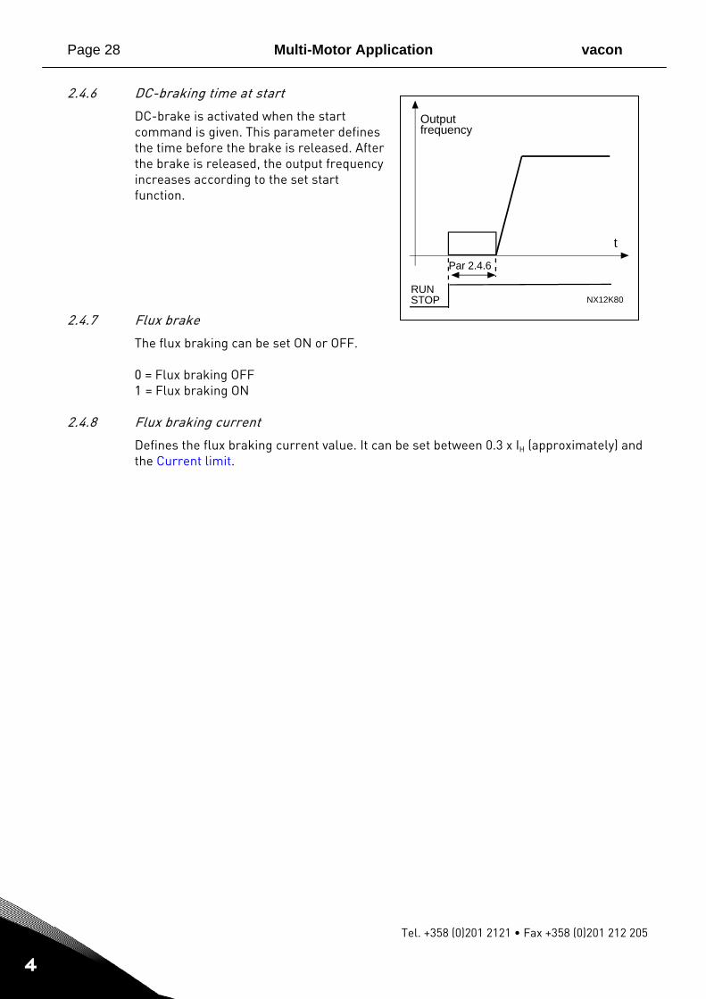
DC-brake is activated when the start command is given. This parameter defines the time before the brake is released. After the brake is released, the output frequency increases according to the set start function.
2.4.7 Flux brake
The flux braking can be set ON or OFF. 0 = Flux braking OFF 1 = Flux braking ON
2.4.8 Flux braking current
Defines the flux braking current value. It can be set between 0.3 x IH (approximately) and the Current limit.
vacon Multi-Motor Application Page 29
24-hour support +358 (0)40 837 1150 • Email: [email protected]
1
4
2.5.1 2.5.2
NX12K33
Reference [Hz]
Outputfrequency [Hz]
Par. 2.5.2
Par. 2.5.1
Par. 2.5.3 = 0,2
Par. 2.5.3 = 1,2
nxlk37.fh8
fout [Hz]
Time [s]
4.5 PROHIBIT FREQUENCIES
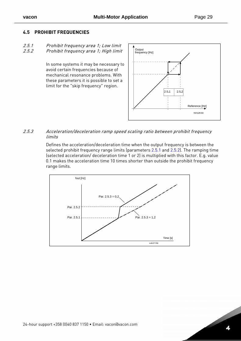
2.5.1 Prohibit frequency area 1; Low limit 2.5.2 Prohibit frequency area 1; High limit
In some systems it may be necessary to avoid certain frequencies because of mechanical resonance problems. With these parameters it is possible to set a limit for the "skip frequency" region.
2.5.3 Acceleration/deceleration ramp speed scaling ratio between prohibit frequency limits
Defines the acceleration/deceleration time when the output frequency is between the selected prohibit frequency range limits (parameters 2.5.1 and 2.5.2). The ramping time (selected acceleration/ deceleration time 1 or 2) is multiplied with this factor. E.g. value 0.1 makes the acceleration time 10 times shorter than outside the prohibit frequency range limits.
Page 30 Multi-Motor Application vacon
Tel. +358 (0)201 2121 • Fax +358 (0)201 212 205
1
4
4.6 MOTOR CONTROL
2.6.1 Motor control mode
0 Frequency control: The I/O terminal and keypad references are frequency references and the frequency converter controls the output frequency (output frequency resolution = 0.01 Hz)
1 Speed control: The I/O terminal and keypad references are speed references and the frequency converter controls the motor speed (accuracy ± 0,5%).
2.6.2 Switching frequency
Motor noise can be minimised using a high switching frequency. Increasing the switching frequency reduces the capacity of the frequency converter unit. Switching frequency for Vacon NXL: 1…16 kHz
2.6.3 Overvoltage controller 2.6.4 Undervoltage controller
These parameters allow the under-/overvoltage controllers to be switched out of operation. This may be useful, for example, if the mains supply voltage varies more than –15% to +10% and the application will not tolerate this over-/undervoltage. This regulator controls the output frequency taking the supply fluctuations into account. Note: Over-/undervoltage trips may occur when controllers are switched out of operation. 0 Controller switched off 1 Controller switched on
vacon Multi-Motor Application Page 31
24-hour support +358 (0)40 837 1150 • Email: [email protected]
1
4
4.7 PROTECTIONS
2.7.1 Response to 4mA reference fault
0 = No response 1 = Warning 2 = Fault, stop mode after fault according to stop function parameter 3 = Fault, stop mode after fault always by coasting A warning or a fault action and message is generated if the 4…20 mA reference signal is used and the signal falls below 3.5 mA for 5 seconds or below 0.5 mA for 0.5 seconds. The information can also be programmed into relay outputs.
2.7.2 Response to external fault
0 = No response 1 = Warning 2 = Fault, stop mode after fault according to stop function parameter 3 = Fault, stop mode after fault always by coasting A warning or a fault action and message is generated from the external fault signal in the programmable digital inputs. The information can also be programmed into relay outputs.
2.7.3 Response to undervoltage fault
1 = Warning 2 = Fault, stop mode after fault according to stop function parameter 3 = Fault, stop mode after fault always by coasting For the undervoltage limits see Vacon NXL, User’s Manual, Table 4-3. Note: This protection can not be inactivated.
2.7.4 Output phase supervision
0 = No response 1 = Warning 2 = Fault, stop mode after fault according to stop function parameter 3 = Fault, stop mode after fault always by coasting Output phase supervision of the motor ensures that the motor phases have an approximately equal current.
2.7.5 Earth fault protection
0 = No response 1 = Warning 2 = Fault, stop mode after fault according to stop function parameter 3 = Fault, stop mode after fault always by coasting Earth fault protection ensures that the sum of the motor phase currents is zero. The overcurrent protection is always working and protects the frequency converter from earth faults with high currents.
Page 32 Multi-Motor Application vacon
Tel. +358 (0)201 2121 • Fax +358 (0)201 212 205
1
4
ffn
par.2.7.8=40%
100%
0N X 1 2 k 6 2
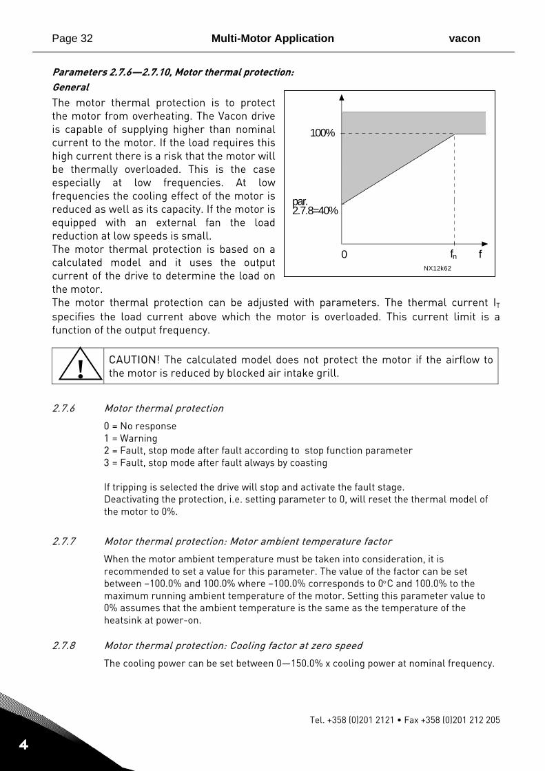
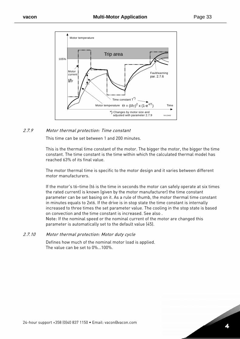
Parameters 2.7.6—2.7.10, Motor thermal protection: General The motor thermal protection is to protect the motor from overheating. The Vacon drive is capable of supplying higher than nominal current to the motor. If the load requires this high current there is a risk that the motor will be thermally overloaded. This is the case especially at low frequencies. At low frequencies the cooling effect of the motor is reduced as well as its capacity. If the motor is equipped with an external fan the load reduction at low speeds is small. The motor thermal protection is based on a calculated model and it uses the output current of the drive to determine the load on the motor. The motor thermal protection can be adjusted with parameters. The thermal current IT specifies the load current above which the motor is overloaded. This current limit is a function of the output frequency.
CAUTION! The calculated model does not protect the motor if the airflow to the motor is reduced by blocked air intake grill.
2.7.6 Motor thermal protection
0 = No response 1 = Warning 2 = Fault, stop mode after fault according to stop function parameter 3 = Fault, stop mode after fault always by coasting If tripping is selected the drive will stop and activate the fault stage. Deactivating the protection, i.e. setting parameter to 0, will reset the thermal model of the motor to 0%.
2.7.7 Motor thermal protection: Motor ambient temperature factor
When the motor ambient temperature must be taken into consideration, it is recommended to set a value for this parameter. The value of the factor can be set between –100.0% and 100.0% where –100.0% corresponds to 0°C and 100.0% to the maximum running ambient temperature of the motor. Setting this parameter value to 0% assumes that the ambient temperature is the same as the temperature of the heatsink at power-on.
2.7.8 Motor thermal protection: Cooling factor at zero speed
The cooling power can be set between 0—150.0% x cooling power at nominal frequency.
!
vacon Multi-Motor Application Page 33
24-hour support +358 (0)40 837 1150 • Email: [email protected]
1
4
2.7.9 Motor thermal protection: Time constant
This time can be set between 1 and 200 minutes. This is the thermal time constant of the motor. The bigger the motor, the bigger the time constant. The time constant is the time within which the calculated thermal model has reached 63% of its final value. The motor thermal time is specific to the motor design and it varies between different motor manufacturers. If the motor's t6–time (t6 is the time in seconds the motor can safely operate at six times the rated current) is known (given by the motor manufacturer) the time constant parameter can be set basing on it. As a rule of thumb, the motor thermal time constant in minutes equals to 2xt6. If the drive is in stop state the time constant is internally increased to three times the set parameter value. The cooling in the stop state is based on convection and the time constant is increased. See also . Note: If the nominal speed or the nominal current of the motor are changed this parameter is automatically set to the default value (45).
2.7.10 Motor thermal protection: Motor duty cycle
Defines how much of the nominal motor load is applied. The value can be set to 0%…100%.
1 0 5 %
par. 2.7.6
Θ = (I/IT)2 x (1-e-t/T)
I /IT
NX12k8 2
Trip area
Mot o r t e m p e r a t u r e
Tim e M otor temperature
Time constant T*)
*) Changes by motor size andadjusted with parameter 2.7.9
Fault/warningM oto r c urre n t
Page 34 Multi-Motor Application vacon
Tel. +358 (0)201 2121 • Fax +358 (0)201 212 205
1
4
f
I
Par. 2.7.12
P a r . 2 . 7 . 1 4 NX12k63
S t a l l a r e a
Par. 2.7.13
NX12k64
Trip a r e a
T i me
Stall time co u n t e r
StallNo stall
T r i p / w a r n i ngp a r . 2 . 7 . 1 1
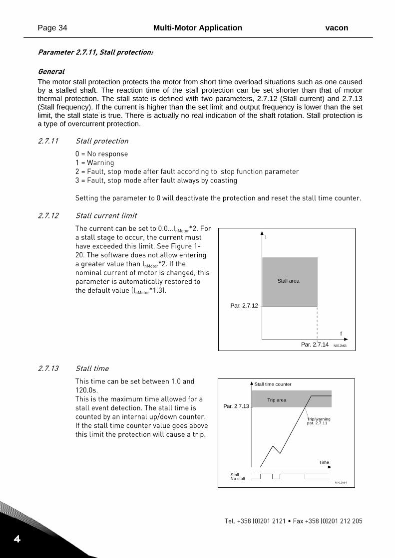
Parameter 2.7.11, Stall protection: General The motor stall protection protects the motor from short time overload situations such as one caused by a stalled shaft. The reaction time of the stall protection can be set shorter than that of motor thermal protection. The stall state is defined with two parameters, 2.7.12 (Stall current) and 2.7.13 (Stall frequency). If the current is higher than the set limit and output frequency is lower than the set limit, the stall state is true. There is actually no real indication of the shaft rotation. Stall protection is a type of overcurrent protection. 2.7.11 Stall protection
0 = No response 1 = Warning 2 = Fault, stop mode after fault according to stop function parameter 3 = Fault, stop mode after fault always by coasting Setting the parameter to 0 will deactivate the protection and reset the stall time counter.
2.7.12 Stall current limit
The current can be set to 0.0…InMotor*2. For a stall stage to occur, the current must have exceeded this limit. See Figure 1- 20. The software does not allow entering a greater value than InMotor*2. If the nominal current of motor is changed, this parameter is automatically restored to the default value (InMotor*1.3).
2.7.13 Stall time
This time can be set between 1.0 and 120.0s. This is the maximum time allowed for a stall event detection. The stall time is counted by an internal up/down counter. If the stall time counter value goes above this limit the protection will cause a trip.
vacon Multi-Motor Application Page 35
24-hour support +358 (0)40 837 1150 • Email: [email protected]
1
4
Par. 2.7.16
NX12k65
Par. 2.7.17
f5 Hz
Underload area
Torque
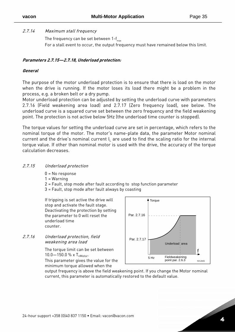
Fieldweakeningpoint par. 2.6.3
2.7.14 Maximum stall frequency
The frequency can be set between 1-fmax For a stall event to occur, the output frequency must have remained below this limit.
Parameters 2.7.15—2.7.18, Underload protection: General The purpose of the motor underload protection is to ensure that there is load on the motor when the drive is running. If the motor loses its load there might be a problem in the process, e.g. a broken belt or a dry pump. Motor underload protection can be adjusted by setting the underload curve with parameters 2.7.16 (Field weakening area load) and 2.7.17 (Zero frequency load), see below. The underload curve is a squared curve set between the zero frequency and the field weakening point. The protection is not active below 5Hz (the underload time counter is stopped). The torque values for setting the underload curve are set in percentage, which refers to the nominal torque of the motor. The motor's name-plate data, the parameter Motor nominal current and the drive's nominal current IL are used to find the scaling ratio for the internal torque value. If other than nominal motor is used with the drive, the accuracy of the torque calculation decreases. 2.7.15 Underload protection
0 = No response 1 = Warning 2 = Fault, stop mode after fault according to stop function parameter 3 = Fault, stop mode after fault always by coasting If tripping is set active the drive will stop and activate the fault stage. Deactivating the protection by setting the parameter to 0 will reset the underload time counter.
2.7.16 Underload protection, field
weakening area load
The torque limit can be set between 10.0—150.0 % x TnMotor. This parameter gives the value for the minimum torque allowed when the output frequency is above the field weakening point. If you change the Motor nominal current, this parameter is automatically restored to the default value.
Page 36 Multi-Motor Application vacon
Tel. +358 (0)201 2121 • Fax +358 (0)201 212 205
1
4
Par. 2.7.18
NX12k66
Trip area
Time
Underload time counter
UnderloadNo underl.
Trip/warningpar. 2.7.15
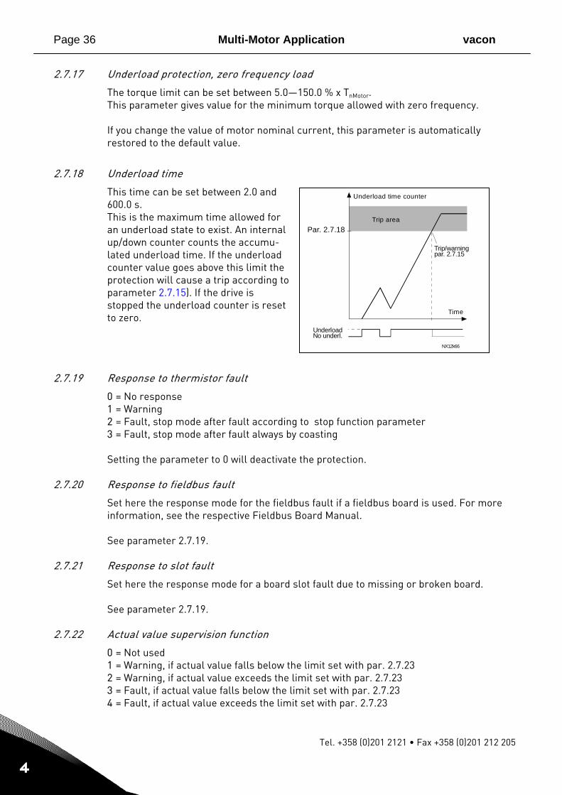
2.7.17 Underload protection, zero frequency load
The torque limit can be set between 5.0—150.0 % x TnMotor. This parameter gives value for the minimum torque allowed with zero frequency. If you change the value of motor nominal current, this parameter is automatically restored to the default value.
2.7.18 Underload time
This time can be set between 2.0 and 600.0 s. This is the maximum time allowed for an underload state to exist. An internal up/down counter counts the accumu-lated underload time. If the underload counter value goes above this limit the protection will cause a trip according to parameter 2.7.15). If the drive is stopped the underload counter is reset to zero.
2.7.19 Response to thermistor fault
0 = No response 1 = Warning 2 = Fault, stop mode after fault according to stop function parameter 3 = Fault, stop mode after fault always by coasting Setting the parameter to 0 will deactivate the protection.
2.7.20 Response to fieldbus fault
Set here the response mode for the fieldbus fault if a fieldbus board is used. For more information, see the respective Fieldbus Board Manual. See parameter 2.7.19.
2.7.21 Response to slot fault
Set here the response mode for a board slot fault due to missing or broken board. See parameter 2.7.19.
2.7.22 Actual value supervision function
0 = Not used 1 = Warning, if actual value falls below the limit set with par. 2.7.23 2 = Warning, if actual value exceeds the limit set with par. 2.7.23 3 = Fault, if actual value falls below the limit set with par. 2.7.23 4 = Fault, if actual value exceeds the limit set with par. 2.7.23
vacon Multi-Motor Application Page 37
24-hour support +358 (0)40 837 1150 • Email: [email protected]
1
4
2.7.23 Actual value supervision limit
With this parameter you can set the limit of actual value supervised by par. 2.7.22
2.7.24 Actual value supervision delay
Set here the delay for the actual value supervision function (par. 2.7.22) If this parameter is in use, the function of par. 2.7.22 will be active only when the actual value stays outside the defined limit for the time determined by this parameter.
Page 38 Multi-Motor Application vacon
Tel. +358 (0)201 2121 • Fax +358 (0)201 212 205
1
4
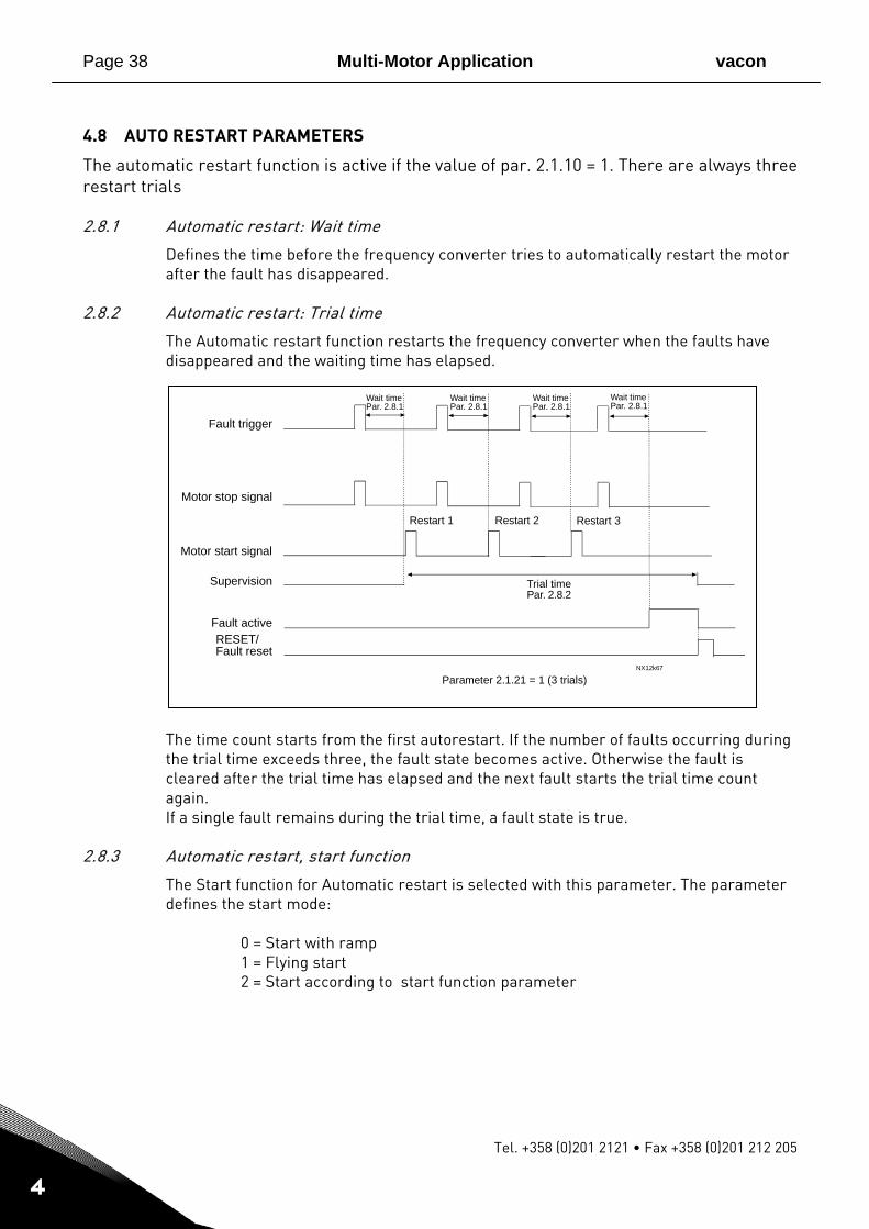
4.8 AUTO RESTART PARAMETERS
The automatic restart function is active if the value of par. 2.1.10 = 1. There are always three restart trials
2.8.1 Automatic restart: Wait time
Defines the time before the frequency converter tries to automatically restart the motor after the fault has disappeared.
2.8.2 Automatic restart: Trial time
The Automatic restart function restarts the frequency converter when the faults have disappeared and the waiting time has elapsed.
The time count starts from the first autorestart. If the number of faults occurring during the trial time exceeds three, the fault state becomes active. Otherwise the fault is cleared after the trial time has elapsed and the next fault starts the trial time count again. If a single fault remains during the trial time, a fault state is true.
2.8.3 Automatic restart, start function
The Start function for Automatic restart is selected with this parameter. The parameter defines the start mode: 0 = Start with ramp 1 = Flying start 2 = Start according to start function parameter
NX12k67
Fault trigger
Motor stop signal
Motor start signal
Supervision
Wait timePar. 2.8.1
Restart 1 Restart 2
Trial timePar. 2.8.2
Fault activeRESET/Fault reset
Parameter 2.1.21 = 1 (3 trials)
Wait timePar. 2.8.1
Wait timePar. 2.8.1
Restart 3
Wait timePar. 2.8.1
vacon Multi-Motor Application Page 39
24-hour support +358 (0)40 837 1150 • Email: [email protected]
1
4
4.9 KEYPAD CONTROL PARAMETERS
3.1 Control place
The active control place can be changed with this parameter. For more information, see Vacon NXL User's Manual, Chapter 7.3.3.
3.2 Keypad reference
The frequency reference can be adjusted from the keypad with this parameter. For more information, see Vacon NXL User's Manual, Chapter 7.3.3.2.
3.3 Keypad direction
0 Forward: The rotation of the motor is forward, when the keypad is the active control place.
1 Reverse: The rotation of the motor is reversed, when the keypad is the active
control place. For more information, see Vacon NXL User's Manual, Chapter 7.3.3.3.
3.4 Stop button activated
If you wish to make the Stop button a "hotspot" which always stops the drive regardless of the selected control place, give this parameter the value 1 (default). See Vacon NXL User's Manual, Chapter 7.3.3. See also parameter 3.1
Vaasa Vacon Plc (Head office and production) Runsorintie 7 65380 Vaasa [email protected] telephone: +358 (0)201 2121 fax: +358 (0)201 212 205
Helsinki Vacon Plc Äyritie 12 01510 Vantaa telephone: +358 (0)201 212 600 fax: +358 (0)201 212 699 Tampere Vacon Plc Vehnämyllynkatu 18 33580 Tampere telephone: +358 (0)201 2121 fax: +358 (0)201 212 750
Vacon Traction Oy Vehnämyllynkatu 18 33580 Tampere telephone: +358 (0)201 2121 fax: +358 (0)201 212 710
sales companies and representative offices:
Austria Vacon AT Antriebssysteme GmbH Aumühlweg 21 2544 Leobersdorf telephone: +43 2256 651 66 fax: +43 2256 651 66 66 Belgium Vacon Benelux NV/SA Interleuvenlaan 62 3001 Heverlee (Leuven) telephone: +32 (0)16 394 825 fax: +32 (0)16 394 827 France Vacon France ZAC du Fresne 1 Rue Jacquard – BP72 91280 Saint Pierre du Perray CDIS telephone: +33 (0)1 69 89 60 30 fax: +33 (0)1 69 89 60 40 Germany Vacon GmbH Gladbecker Strasse 425 45329 Essen telephone: +49 (0)201 806 700 fax: +49 (0)201 806 7099 Great Britain Vacon Drives (UK) Ltd. 18, Maizefield Hinckley Fields Industrial Estate Hinckley LE10 1YF Leicestershire telephone: +44 (0)1455 611 515 fax: +44 (0)1455 611 517
Italy Vacon S.p.A. Via F.lli Guerra, 35 42100 Reggio Emilia telephone: +39 0522 276811 fax: +39 0522 276890 The Netherlands Vacon Benelux BV Weide 40 4206 CJ Gorinchem telephone: +31 (0)183 642 970 fax: +31 (0)183 642 971 Norway Vacon AS Langgata 2 3080 Holmestrand telephone: +47 330 96120 fax: +47 330 96130 PR China Vacon Suzhou Drives Co. Ltd. Building 13CD 428 Xinglong Street Suchun Industrial Square Suzhou 215126 telephone: +86 512 6283 6630 fax: +86 512 6283 6618
Vacon Suzhou Drives Co. Ltd. Beijing Office A205, Grand Pacific Garden Mansion 8A Guanhua Road Beijing 100026 telephone: +86 10 6581 3734 fax: +86 10 6581 3754
Russia ZAO Vacon Drives Bolshaja Jakimanka 31, stroenie 18 109180 Moscow telephone: +7 (095) 974 14 47 fax: +7 (095) 974 15 54
ZAO Vacon Drives 2ya Sovetskaya 7, office 210A 191036 St. Petersburg telephone: +7 (812) 332 1114 fax: +7 (812) 279 9053 Singapore Vacon Plc Singapore Representative Office 102F Pasir Panjang Road #02-06 Citilink Warehouse Complex Singapore 118530 telephone: +65 6278 8533 fax: +65 6278 1066 Spain Vacon Drives Ibérica S.A. Miquel Servet, 2. P.I. Bufalvent 08243 Manresa telephone: +34 93 877 45 06 fax: +34 93 877 00 09 Sweden Vacon AB Torget 1 172 67 Sundbyberg telephone: +46 (0)8 293 055 fax: +46 (0)8 290 755
Vacon distributor: