Vacon Baltic Days
22
Vacon Baltic Days 22.-23.9.2011 Tallinn, Estonia Vacon Technology Yrjö Karvonen Technical Account Manager
Transcript of Vacon Baltic Days

Vacon Baltic Days22.-23.9.2011 Tallinn, Estonia Vacon Technology
Yrjö KarvonenTechnical Account Manager

9/22/2011 2
Frequency converter
Why to use
Energy saving
Easy to control (mA, V, digital I/O, Fieldbusses)
Better process quality
More volyme in production
No stress for supply network when starting motor
Limits mechanical stress for machines
Applications
Pums, fans
Conveyors
Compressors
Cranes, lifts
Extruders, mixer
Paper machines etc.

9/22/2011 3
Use of frequency converters started to be more and more common after 1980 thanks to to new semiconductor technology which made possible to make new speed regulation system the industry was waiting for i.e at the same time:
• stepless
• easy to control
• almost maintenance free
Frequency converters

9/22/2011 4
0 1500
T/Tn
1
2
2
4
6I/In
n/rpm
1
2
3
4
5
1. Supply starting current DOL
2. Starting torque DOL
3. Starting motor torque VSD
(Depends on set current limit and ramp up time )
4. Supply starting current VSD
5. Starting motor current VSD
Starting current and torque
FC M3-ph
Torque <0.5*Torque of DOL
Supply start current <1/6*Current DOL
Supply voltage drop <1/6*drop DOL
9/22/2011 5
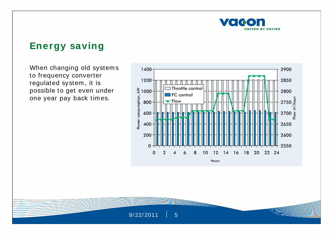
Energy saving
When changing old systems to frequency converter regulated system, it is possible to get even under one year pay back times.

9/22/2011 6
Pulse width modulation ( PWM ) frequency converter
Uin 50Hz 3 vSinus mode
0- Uin, 0…500 Hz3 v, PWM
Control I/O
Monitor
Motor control

9/22/2011 7
Supply of frequency converter
Standard freq. converters have 6-pulse rectifier
• cos > 0.98 No need for copmpensation batteries ( Note. Not allowed to connectcompensation capacitors to VSD output )
• Supply network powerproportional to shaft power P =
*T
• Supply current has harmonics of order n*p(+/- 1 ), p=pulsenumber of rectifier. Orders of harmonic components of 6-pulse rectifier are 5th,7th,11th,13th ... = ( 250Hz ,350Hz ... )
Typical input current waveform of 6-pulse rectifier.

9/22/2011 8
Supply of frequency converter/harmonics
Amplitude of harmonic currents is strongly depending on whether fc has provided with choke or not. Choke can be whether in AC or DC circuit.
Choke / %
Total current distortion/ %

9/22/2011 9
Supply of frequency converter/harmonics
Harmonic current of individual devices is notmost important but the influence of totalharmonic current content generated by all equipmentconnected to network ( SUM In ( n=2.... ) whichis then generating voltage distortion . Total voltage distortion ( THD ) is then meter to evaluate the condition of network. Standards take into account both THD and set also limitsfor individual voltage harmonics components.
High voltage distortion causes:• Extra load for cables and transformers• Extra load for compensation capacitors• Can cause malfunctions or extra losses on units
connected to distorted network

9/22/2011 10
Supply of frequency converter/harmonicsHow to decrease
3~M
~~
=
=
YLV
LV= 30°
3~M
~~
=
=
3~M
~~
=
=
3~M
~~
=
=
3~M
~
~=
=
~
=
LV
3~M
~
~=
=
Passive filter
Active filter
12 - or 18 – pulse rectifier
Dividing the loads after different vector groups
9/22/2011 11
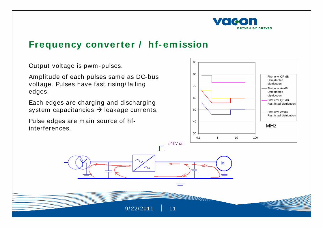
Frequency converter / hf-emission
Output voltage is pwm-pulses.
Amplitude of each pulses same as DC-bus voltage. Pulses have fast rising/falling edges.
Each edges are charging and discharging system capacitancies leakage currents.
Pulse edges are main source of hf-interferences.
30
40
50
60
70
80
90
0,1 1 10 100
First env. QP dBUnrestricteddistributionFirst env. Av dBUnrestricteddistributionFirst env. QP dB.Restricted distribution
First env. Av dB.Restricted distribution
MHz

9/22/2011 12
Frequency converter / hf-emission
EMC standard concerning frequency converters
( EMC = Electromagnetic compatibility)
EN 61800 –3 + Amendment A11 ( Adjustable speed electrical power drive systems. Part 3: EMC product standard including specific test methods. )
Standard defines limits/tests for immunity and emission .
There are 2 separate classes for environment:
1) First environment = Public network
2) Second environment = own distribution transformer ( industrial network ) = C3 = Class 3
First environment is having 2 separate sub categories:
1) Unrestricted distribution = C1 = Class 1
2) Restricted distribution = C2 = Class 2

9/22/2011 13
Frequency converter / hf-emission
Net owner has his own ” responsibility and freedom ”.
PCC ( Point of common coupling ).
Standard makes no requirements:
• When IT- network
• When rated current over 400 A
• When voltage over 1000 V
• When filtering makes some other major problems

9/22/2011 14
Frequency converter / hf-emission
To prevent emc-problems
• Select correct type of VSD; Vacon has different inbuilt filters available .External filters available as well.
• Select correct power cable types. Best is to use special cable types which have hf-screen. For example MCCMK. MCMK is standard under ground cable and screen of it is not made for hf-protection. Motor cable is the major source of interference.
• Interferences produced by VSD are having high frequencies. That’s why earthing of cable screens should be done in both ends of cable. This concerns both power cables and control cables.
•360 degree earthing is best. If not easy to make in practise, make hf-earhing so close the cable jacket stripping point as possible ( within 0...3 cm )
• Keep motor cables separate from other cables.

9/22/2011 15
Frequency converter/ motor
• FC makes possible to regulate standard squirrel cage motor stepless within wide speed area
• Can be used also with slip ring motors and permanents magnet motors.
Constant flux areaField weakening area
Motor loadability
Starting torque
Overload 1 min
Motor nominal torque
Motor continousloadability when fedBy frequency converter

9/22/2011 16
Frequency converter/ motor• Constant flux area
- Motor internal flux can be kept constant by increasing U as function of f ( U/f=constant )
- When constant flux, T is proportional to effective current.
- At very low frequencies U/f-curve has to be lifted in order to keep constant flux ( IR-compensation )
- Continous loadability of motor goes down at low frequencies due lower speed of motor shaft cooling fan.
• Field weakening area
- Motor flux goes down due U/f goes down.
- Motor max. torque goes down ( fn/f )²
- Motor continous torque goes down ( fn/f ) ( constant current )
- Life time of bearings is shorter

9/22/2011 17
Frequency converter/ motor
• Motor protection
-FC calculates motor thermal image as a function of set motor datas, actual motor current and speed.
-Ultra fast short circuit protection ( < 10 us ) , when short circuit on motor cable or inside motor.

9/22/2011 18
Frequency converter/ motor/ motor insulation
Udc
dU
dt
Typical switching times
for different components
SCR 4.0 us
GTO 1.0 us
GTR 0.8 us
IGBT 0.1-0.2 us
IGBTdU/dt = 5…10 kV/us
Edges of PWM pulses make extra stress for motor insulation.
High du/dt increases risk of partial discharges inside insulation.
9/22/2011 19
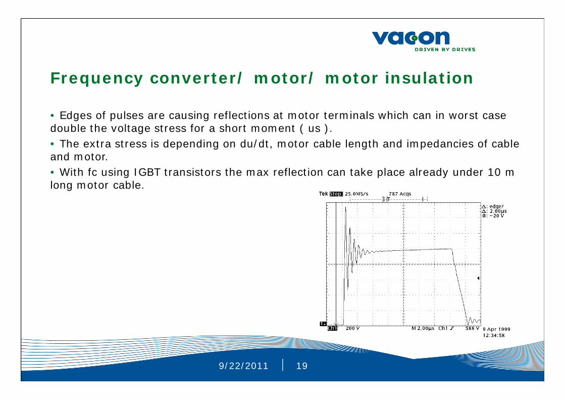
Frequency converter/ motor/ motor insulation
• Edges of pulses are causing reflections at motor terminals which can in worst case double the voltage stress for a short moment ( us ). • The extra stress is depending on du/dt, motor cable length and impedancies of cable and motor.• With fc using IGBT transistors the max reflection can take place already under 10 m long motor cable.

9/22/2011 20
Frequency converter/ motor/ motor insulation
Motor suitability to frequency converter use has to be checked from motor supplier !!!
Some common practise with few big motor suppliers:
400 V net: Standard motor series can be used
500 V net: On the limit. Some of motor suppliers promise to use standard motor.
690 V net: Typically combination is motor with reinforced insulation + du/dt filter after fc.
9/22/2011 21
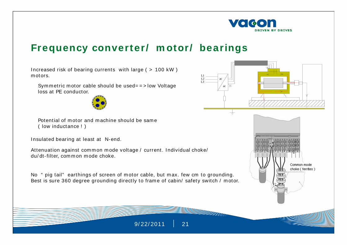
Frequency converter/ motor/ bearings
ac
ac
L1L2L3
Increased risk of bearing currents with large ( > 100 kW ) motors.
Symmetric motor cable should be used==>low Voltage loss at PE conductor.
Potential of motor and machine should be same ( low inductance ! )
Insulated bearing at least at N-end.
Attenuation against common mode voltage / current. Individual choke/ du/dt-filter, common mode choke.
No “ pig tail” earthings of screen of motor cable, but max. few cm to grounding. Best is sure 360 degree grounding directly to frame of cabin/ safety switch / motor.

9/22/2011 22
THANK YOU