
Vaccuperm VGB-103 - Grundfosnet.grundfos.com/Appl/WebCAPS/Grundfosliterature-1665250.pdf · warning...
24
GRUNDFOS ALLDOS INSTRUCTIONS Vaccuperm VGB-103 Compact dosing regulator Service instructions
Transcript of Vaccuperm VGB-103 - Grundfosnet.grundfos.com/Appl/WebCAPS/Grundfosliterature-1665250.pdf · warning...

GRUNDFOS ALLDOS INSTRUCTIONS
Vaccuperm VGB-103Compact dosing regulator
Service instructions
2 / 24
Contents
1. Of general interest ............................................................................................................ 31.1 Structure of the documentation .........................................................................................................31.2 About this manual .............................................................................................................................31.3 User/target groups ............................................................................................................................31.4 Responsibilities of the operator.........................................................................................................41.5 Maintenance and service personnel ..................................................................................................41.6 Correct usage ...................................................................................................................................41.7 Inappropriate usage ..........................................................................................................................42. Technical Data................................................................................................................... 52.1 Type key VGB-103............................................................................................................................52.2 General data.....................................................................................................................................62.3 Dimensioned drawing .......................................................................................................................73. Installation ......................................................................................................................... 73.1 Transport and storage.......................................................................................................................73.2 Unpacking ........................................................................................................................................73.3 Typical installation ............................................................................................................................83.4 Mounting...........................................................................................................................................84. Commissioning ................................................................................................................. 94.1 Preparations for commissioning ........................................................................................................94.2 Checks before commissioning ........................................................................................................105. Maintenance .................................................................................................................... 125.1 Possible faults ................................................................................................................................125.2 Cleaning the Inlet Valve ..................................................................................................................135.3 Cleaning the measuring tube ..........................................................................................................145.4 Cleaning the rate valve ...................................................................................................................165.5 Cleaning the vacuum regulator .......................................................................................................186. Spare Parts ...................................................................................................................... 19
1. Of general interest
1.1 Structure of the documentationThe Grundfos Alldos device VGB-103 is a state-of-the-art solution, which complies with recognised safety regulations.Conformity with applicable standards, directives and laws has been verified. Nevertheless, certain risks which cannot be prevented by the manufacturer are associated with the use of the system.Purpose of this manual: • Inform users of optimum use.• Warn users of possible residual risks when using correctly and identify measures that should be taken to avoid
damage.• Caution users against obvious misuse or inappropriate use and inform them of the necessary care that must be
taken when operating the system.
1.2 About this manualThis manual contains the following standardised safety instructions about possible residual risks:
Information about possible residual risks is provided:• On warning signs displayed in the installation location.• At the start of each section in this manual.• Directly before any operating procedures that could involve residual risks.
1.3 User/target groupsUsers are persons who are responsible for operating and monitoring the device VGB-103 at the installation location. The system may only be operated by trained and qualified personnel. Personnel must have appropriate technical knowledge and be familiar with the basic principles of measuring and control technology.
1.3.1 Responsibilities of the usersThe users’ responsibilities• Read this manual before operating the VGB-103.• Be trained by qualified personnel from Grundfos Alldos in the operation of the system.• Observe the recognised regulations governing safety in the workplace and accident prevention.• Wear appropriate protective clothing in accordance with national regulations for the prevention of accidents when
operating the system and handling chemicals (German GUV-V D05).
WarningThese operating instructions are also available on www.Grundfosalldos.com.Prior to installation, read these installation and operating instructions. Installation and operation must comply with local regulations and accepted codes of good practice.
WarningIf these safety instructions are not observed, it may result in personal injury!
CautionIf these safety instructions are not observed, it may result in malfunction or damage to the equipment!
Note Notes or instructions that make the job easier and ensure safe operation.
3 / 24

1.4 Responsibilities of the operatorThe owner of the building or operator of the VGB-103 is responsible for the following:• Consider this manual to be part of the product and ensure that it is kept clearly accessible in the immediate vicinity
of the system for the entire service life of the system.• Meet the installation requirements specified by the manufacturer (required water connections and fittings,
environmental conditions, electrical connection, protective pipe for dosing line if necessary, audible or optical warning device for alarm messages if necessary).
• Ensure that water lines and fixings are regularly checked, serviced and maintained.• Obtain official approval for storing chemicals, if necessary.• Train users in the operation of the system.• Ensure that the regulations for the prevention of accidents are observed in the installation location (German GUV-
V D05 regulation for the prevention of accidents, "Chlorination of Water" dated January 1997).• Provide all users and service personnel with protective clothing in accordance with GUV-V D05 (face mask, gloves,
protective apron).
1.5 Maintenance and service personnelThe system may only be maintained and serviced by authorised service personnel from Grundfos Alldos.
1.6 Correct usageThe Grundfos Alldos VGB-103 may be used for dosing chlorine, Cl2, as being described in this manual.
1.7 Inappropriate usageApplications other than those listed in section 1.6 Correct usage are considered not to be in accordance with the intended use and are not permitted. The manufacturer, Grundfos Alldos, accepts no liability for any damage resulting from incorrect use.The system comprises state-of-the-art components and has undergone safety-related testing.
WarningUnauthorised structural modifications to the system may result in serious damage to equipment and personal injury. It is forbidden to open, modify, change the structure of, bridge, remove, bypass or disable components, especially safety equipment.
4 / 24

2. Technical Data
2.1 Type key VGB-103Example: Compact dosing regulator Type key VGB-103-250/1-S-1-O, BO
Code Example VGB-103 -250 /1 -S -1 -O , -B 0
Vaccuperm Gas Basic = VGB
Dosing flow
100 5 - 100 g/h250 10 - 250 g/h500 25 - 500 g/h
1000 50 - 1000 g/h2000 100 - 2000 g/h3000 150 - 3000 g/h4000 400 - 4000 g/h
Pressure connection
1 G 12 G 3/43 Yoke USA
Inlet valve
B Basic only with bottleS Short only with bottleL Long, 230-240V/50-60Hz only with drumM Long, 110-115V/50-60Hz only with drum
Pressure indication
0 No pressure gauge1 With pressure gauge bottle: connection left drum: connection on top
Filter
O OutsideU Inside
Direct installation
B Bottle, pressure input frontalD Drum, pressure input left
Residual pressure device
1 Yes0 No
5 / 24

2.2 General data
2.2.1 Dosing Flow
2.2.2 Pressure indication
2.2.3 Pressure connection (inlet)
2.2.4 Accessories (not including)
Accuracy ± 4 % of upper limitControl range 1 : 20Empty indication Optical empty indicationFlow meter According to the floater principle, length of the measuring tube 70 mmWeight 1 kg
5-100 g/h 0.2-5 lbs/day10-250 g/h 0.5-14 lbs/day25-500 g/h 1.5-26 lbs/day50-1000 g/h 2.5-50 lbs/day100-2000 g/h 5-100 lbs/day150-3000 g/h 10-150 lbs/day400-4000 g/h 30-220 lbs/day
VersionWith pressure gaugeNo pressure gauge
VersionClosed yoke (USA)Union nut G 1Union nut G 3/4
Vacuum connection (to the injector) for hose 8/11Overpressure connection for hose 8/11
Installation material: Hoses of different lengthsHolding plate for wall fixing at change of containerTest medium for leak search
6 / 24

0
2.3 Dimensioned drawing
Fig. 1 Dimensioned drawing of chlorine compact device
3. Installation
3.1 Transport and storage• Handle with care, do not throw!• Dry and cool storage place.
3.2 Unpacking• Observe when unpacking:
– No humidity should get into gas-leading parts!– No foreign matter should get into gas-leading parts!
• Check the scope of delivery.• Mount as soon as possible after unpacking.
TM04
070
6 09
08
VGB-103
131.7
82.492
31.4 ca. 197
101
71.1
14 40.3
126
146
63
bar 160
Cl 2
0°C
ALL
DO
S2
187.8
81.8
125
ca.
100
31.4
ca. 257
Closed yoke,G1 or G3/4
Pressure gauge G1
7 / 24
3.3 Typical installation
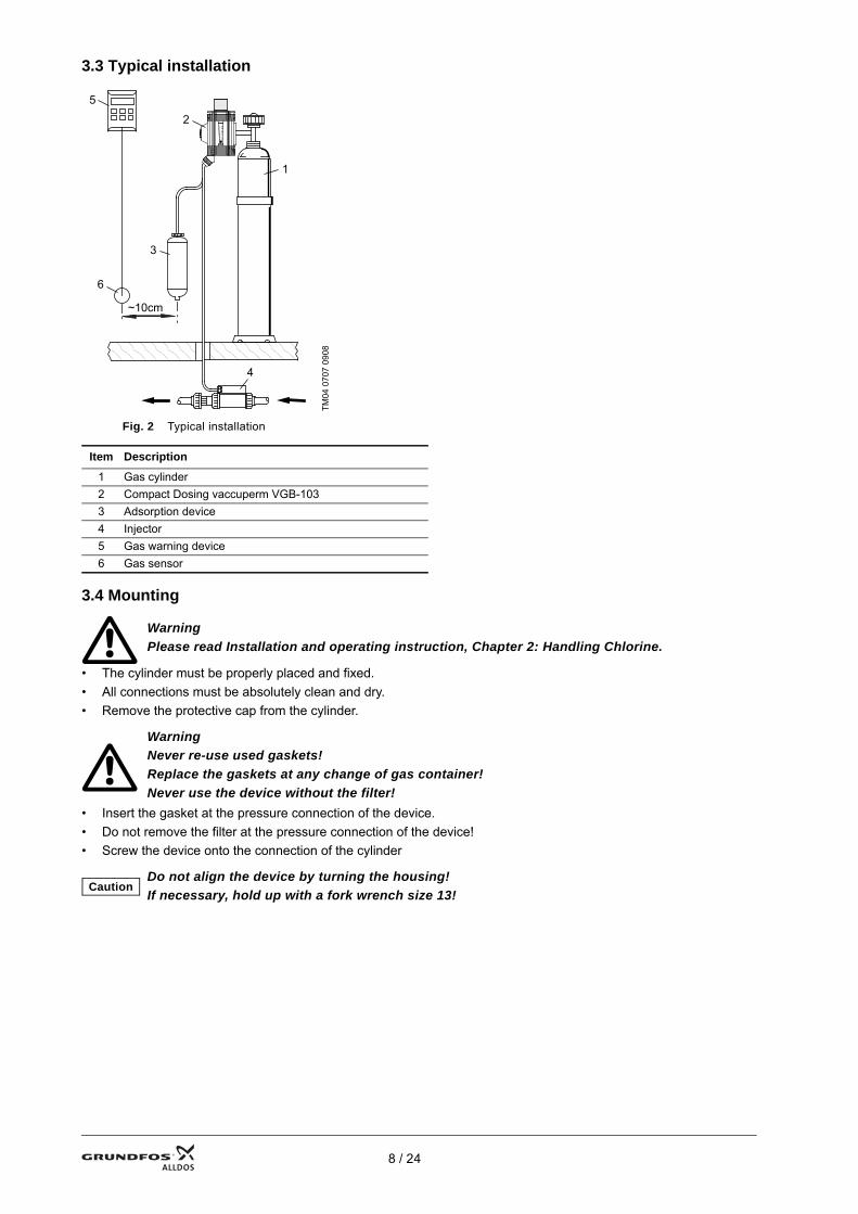
Fig. 2 Typical installation
3.4 Mounting
• The cylinder must be properly placed and fixed.• All connections must be absolutely clean and dry.• Remove the protective cap from the cylinder.
• Insert the gasket at the pressure connection of the device.• Do not remove the filter at the pressure connection of the device!• Screw the device onto the connection of the cylinder
TM04
070
7 09
08
Item Description
1 Gas cylinder2 Compact Dosing vaccuperm VGB-1033 Adsorption device4 Injector5 Gas warning device6 Gas sensor
WarningPlease read Installation and operating instruction, Chapter 2: Handling Chlorine.
WarningNever re-use used gaskets! Replace the gaskets at any change of gas container!Never use the device without the filter!
CautionDo not align the device by turning the housing!If necessary, hold up with a fork wrench size 13!
1
2
3
4
5
6
~10cm
8 / 24
4. Commissioning
4.1 Preparations for commissioning
4.1.1 Vacuum connections
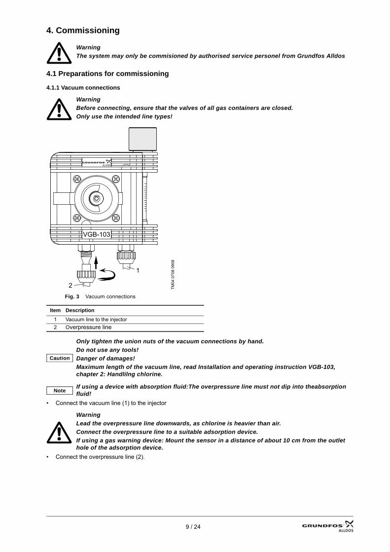
Fig. 3 Vacuum connections
• Connect the vacuum line (1) to the injector
• Connect the overpressure line (2).
WarningThe system may only be commisioned by authorised service personel from Grundfos Alldos
WarningBefore connecting, ensure that the valves of all gas containers are closed.Only use the intended line types!
TM04
070
8 09
08
Item Description
1 Vacuum line to the injector2 Overpressure line
Caution
Only tighten the union nuts of the vacuum connections by hand.Do not use any tools!Danger of damages!Maximum length of the vacuum line, read Installation and operating instruction VGB-103, chapter 2: Handlilng chlorine.
NoteIf using a device with absorption fluid:The overpressure line must not dip into theabsorption fluid!
WarningLead the overpressure line downwards, as chlorine is heavier than air.Connect the overpressure line to a suitable adsorption device.If using a gas warning device: Mount the sensor in a distance of about 10 cm from the outlet hole of the adsorption device.
1
2
VGB-103
9 / 24

4.2 Checks before commissioningCheck tightness of the total plant before start-up
4.2.1 Checking the gas solution lines and the non-return diaphragm of the injector• Observe the manual of the injector!
4.2.2 Checking the tightness (media Cl2)
Fig. 4 No liquid ammonia
Checking the pressure connections (after changing gas cylinder)• Open the cylinder valve and quickly close it again.• Slowly pass the open ammonia bottle along gas-leading parts.
– Slightly presss the bottle in a pumping manner, allowing the ammonia mist to rise up.– Formation of white mist: Leakage at the pressure connection!
• Depressurize the plant!• Eliminate leakage!• Check tightness againFormation of white mist --> pressure connection is not tight
Fig. 5 Ammonia + chlorine gas --> formation of white mist
No formation of white mist --> pressure connection is tight
Fig. 6 No chlorine gas --> no formation of white mist
WarningCheck the tightness not until the total plant is ready for start-up.Danger of gas leakage!
WarningLiquid ammonia must not come in contact with parts of the plant!Danger of leakages by corrosion!
TM04
070
9 09
08
TM04
071
0 09
08
TM04
071
1 09
08
!!
✓
10 / 24

Checking the inlet valve• Remove the union nut at the overpressure connection and take off the overpressure line.• Close the rate valve.• Open the cylinder valve.• Slowly pass the open ammonia bottle along the overpressure connection.
– Slightly press the bottle in a pumping manner, allowing the ammonia mist to rise up.– Formation of white mist: The inlet valve is not tight!
• Depressurize the plant!• Check the inlet valve and repair it!• Check tightness againFormation of white mist --> the inlet valve is not tight!
Fig. 7 Ammonia + chlorine gas --> formation of white mist
No formation of white mist --> the inlet valve is tight!
Fig. 8 No chlorine gas --> no formation of white mist
TM04
071
2 09
08
TM04
071
3 09
08
VGB-103
VGB-103
✓
11 / 24

5. MaintenanceRates for cleaning and maintenance:• at least every 12 months• in case of malfunction
5.1 Possible faults
WarningSwitch off the whole plant before doing cleaning and maintenance work!Danger of gas break-out!
WarningBefore re-starting, check the tightness!Danger of gas break-out!
Fault Cause Correction
Gas leakage at the pressure connection.
The sealing surface at the pressure connection of the device is damaged. If necessary, replace the inlet valve.
The gasket at the pressure connection is damaged. Replace the gasket.Sealingsurfaces are dirty, there are rests of old gaskets on the sealing surfaces. Clean the sealing surfaces.
The sealing surface at the connection of the gas cylinder is damaged. Use a different gas cylinder.
The pressure connection is loose. Tighten the pressure connection.
Gas escapes at the overpressure line.
The inlet valve is soiled or damaged. Clean the inlet valve, replace damaged parts.
Re-liquefacted gas enters the inlet valve. Reduce the extraction amount, ensure correct course of temperature.
Formation of ice on the gas cylinder.
The extraction amount per hours is higher than 1% of the contents of the gas cylinder, the system is too small.
Use a dosing system with more than one gas cylinders.
Desired dosing flow is not reached.
Wrong adjusting spindle (diameter too low). Mount the correct adjusting spindle.
Insufficient injector vacuum.
Check the injector, repair it if necessary. Observe the manual of the injector.Check the motive water pump, repair it if necessary.Check the dirt trap before the injector, clean it if necessary.
Leakage in vacuum line between dosing unit and injector. Eliminate the leackage.
Vacuum line is dirty. Replace the vacuum line.The valve of the gas cylinder is closed. Open the valve of the gas cylinder.The gas cylinder is empty. Replace the empty gas cylinder by a new one.
The ball in the measuring tube is caught. Measuring tube and/or ball are soiled. Clean the measuring tube and the ball.
Water in the measuring tube. Non-return diaphragm of the injector is defective.
Repair the injector. Completely disassemble the dosing unit, clean it and dry it perfectly! Dry the vacuum line to the injector or replace it.
12 / 24

5.2 Cleaning the Inlet Valve
5.2.1 Required tools and accessories• Hot water (ca. 40°C)• Soft brush• Crosstip screwdriver• Screwdriver• Cylindrical pin (Ø ca. 5 mm)
5.2.2 Procedure• Unscrew the cover at the inlet side and take it off.
Fig. 9 Take off inlet valve
• Take out the filter and the gasket
Fig. 10 Take off gasket and filter
• Unscrew the valve cone. Take out the screw part and the spring. • Press out the valve seat with the cylindrical pin
Fig. 11 Inlet valve demount
TM04
071
8 09
08
TM04
071
9 09
08
TM04
072
0 09
08
13 / 24
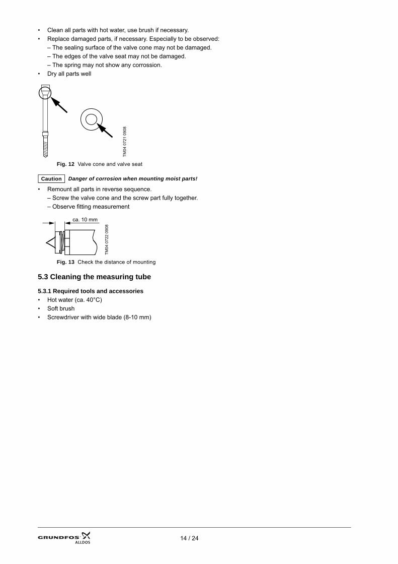
• Clean all parts with hot water, use brush if necessary.• Replace damaged parts, if necessary. Especially to be observed:
– The sealing surface of the valve cone may not be damaged.– The edges of the valve seat may not be damaged.– The spring may not show any corrossion.
• Dry all parts well
Fig. 12 Valve cone and valve seat
• Remount all parts in reverse sequence.– Screw the valve cone and the screw part fully together.– Observe fitting measurement
Fig. 13 Check the distance of mounting
5.3 Cleaning the measuring tube
5.3.1 Required tools and accessories• Hot water (ca. 40°C)• Soft brush• Screwdriver with wide blade (8-10 mm)
TM04
072
1 09
08
Caution Danger of corrosion when mounting moist parts!
TM04
072
2 09
08
ca. 10 mm
14 / 24
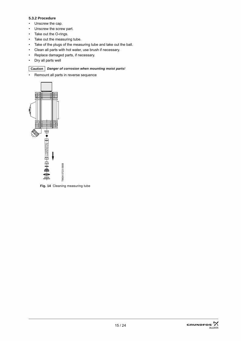
5.3.2 Procedure• Unscrew the cap.• Unscrew the screw part.• Take out the O-rings.• Take out the measuring tube.• Take of the plugs of the measuring tube and take out the ball.• Clean all parts with hot water, use brush if necessary.• Replace damaged parts, if necessary.• Dry all parts well
• Remount all parts in reverse sequence
Fig. 14 Cleaning measuring tube
Caution Danger of corrosion when mounting moist parts!
TM04
072
3 09
08
15 / 24

5.4 Cleaning the rate valve
5.4.1 Required tools and accessories• Hot water (ca. 40°C)• Soft brush• Special tool 91835362 (48.541)• Cylindrical pin (Ø ca. 5 mm)• PTFE grease
Fig. 15 Inlet valve mounted
TM04
072
4 09
08
16 / 24

5.4.2 Procedure• Unscrew the adjustment knob.• Unscrew the rate valve cartridge.• Take out the flat gasket
• Remove the O-ring of the rate valve cartridge.• Press out the seat with the cylindrical pin.• Take off the cap of the adjustment knob.• Remove the locking ring and take out the spindle.• Remove the O-rings of the spindle.• Clean all parts with hot water, use brush if necessary• Replace damaged parts, if necessary.• Dry all parts well
• Replace the flat gasket by a new one
• Replace the O-rings of the spindle by new ones, slightly apply Teflon grease to them.• Replace the O-ring of the rate valve cartridge.• Remount all parts in reverse sequence.
– Observe fitting position of the valve seat
Fig. 16 Observe fitting position of the valve seat
Caution Do not damage the sealing edge of the valve seat!
Caution Danger of corrosion when mounting moist parts!
Caution No grease must get into the longitudinal groove of the spindle!
TM04
072
5 09
08
17 / 24
5.5 Cleaning the vacuum regulator
5.5.1 Required tools and accessories• Hot water (ca. 40°C)• Soft brush• Crosstip screwdriver
5.5.2 Procedure
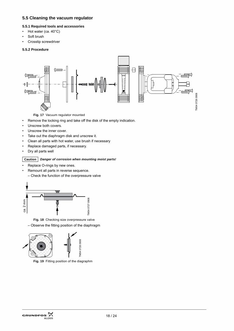
Fig. 17 Vacuum regulator mounted
• Remove the locking ring and take off the disk of the empty indication.• Unscrew both covers.• Unscrew the inner cover.• Take out the diaphragm disk and unscrew it.• Clean all parts with hot water, use brush if necessary• Replace damaged parts, if necessary.• Dry all parts well
• Replace O-rings by new ones.• Remount all parts in reverse sequence.
– Check the function of the overpressure valve
Fig. 18 Checking size overpressure valve
– Observe the fitting position of the diaphragm
Fig. 19 Fitting position of the diagraphm
TM04
072
6 09
08
Caution Danger of corrosion when mounting moist parts!
TM04
072
7 09
08
TM04
072
8 09
08
ca. 2
mm
18 / 24
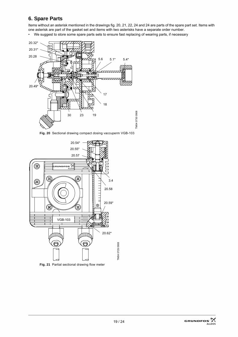
6. Spare PartsItems without an asterisk mentioned in the drawings fig. 20, 21, 22, 24 and 24 are parts of the spare part set. Items with one asterisk are part of the gasket set and items with two asterisks have a separate order number.• We suggest to store some spare parts sets to ensure fast replacing of wearing parts, if necessary
Fig. 20 Sectional drawing compact dosing vaccuperm VGB-103
Fig. 21 Partial sectional drawing flow meter
TM04
073
0 09
08
TM04
072
9 09
08
17
18
19 23 30
20.32*
5.6 5.1* 5.4*
20.31*
20.28
20.49*
20.54*
20.62*
3.4
20.59*
20.55*
20.57
20.58
VGB-103
19 / 24
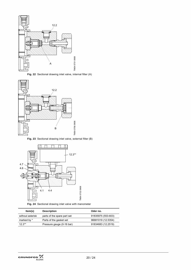
Fig. 22 Sectional drawing inlet valve, internal filter (A)
Fig. 23 Sectional drawing inlet valve, external filter (B)
Fig. 24 Sectional drawing inlet valve with manometer
TM04
073
1 09
08TM
04 0
756
0908
TM04
073
2 09
08
Item(s) Description Oder no.
without asterisk parts of the spare part set 91835975 (553-603)marked by * Parts of the gasket set 96681019 (12.5354)12.3** Pressure gauge (0-16 bar) 91834683 (12.2519)
12.2
A
12.2
B
4.4 4.1
4.7 4.6
12.3**
20 / 24

21 / 24

22 / 24

23 / 24
24
ArgentinaBombas GRUNDFOS de Argentina S.A.Ruta Panamericana km. 37.500 Lote 34A1619 - GarinPcia. de Buenos AiresPhone: +54-3327 414 444Telefax: +54-3327 411 111AustraliaGrundfos AlldosDosing & DisinfectionALLDOS Oceania Pty. Ltd.Unit 3 / 74 Murdoch CircuitAcacia Ridge QLD 4100Phone: +61 (0)7 3712 6888Telefax: +61 (0)7 3272 5188E-mail: [email protected] AustraliaGRUNDFOS Pumps Pty. Ltd. P.O. Box 2040 Regency Park South Australia 5942 Phone: +61-8-8461-4611 Telefax: +61-8-8340 0155 AustriaGRUNDFOS Pumpen Vertrieb Ges.m.b.H.Grundfosstraße 2 A-5082 Grödig/Salzburg Tel.: +43-6246-883-0 Telefax: +43-6246-883-30 BelgiumN.V. GRUNDFOS Bellux S.A. Boomsesteenweg 81-83 B-2630 Aartselaar Tél.: +32-3-870 7300 Télécopie: +32-3-870 7301BelorussiaПредставительство ГРУНДФОС в Минске220123, Минск,ул. В. Хоружей, 22, оф. 1105Телефон: (37517) 233-97-65Факс: (37517) 233-97-69Bosnia/HerzegovinaGRUNDFOS SarajevoParomlinska br. 16,BiH-71000 SarajevoPhone: +387 33 713290Telefax: +387 33 231795BrazilMark GRUNDFOS Ltda.Av. Humberto de Alencar Castelo Branco, 630CEP 09850 - 300São Bernardo do Campo - SPPhone: +55-11 4393 5533Telefax: +55-11 4343 5015BulgariaGRUNDFOS Pumpen VertriebRepresentative Office - BulgariaBulgaria, 1421 SofiaLozenetz District105-107 Arsenalski blvd. Phone: +359 2963 3820, 2963 5653Telefax: +359 2963 1305CanadaGRUNDFOS Canada Inc. 2941 Brighton Road Oakville, Ontario L6H 6C9 Phone: +1-905 829 9533 Telefax: +1-905 829 9512 ChinaGrundfos AlldosDosing & DisinfectionALLDOS (Shanghai) Water Technology Co. Ltd.West Unit, 1 Floor, No. 2 Building (T 4-2)278 Jinhu Road, Jin Qiao Export Processing ZonePudong New Area Shanghai, 201206Phone: +86 21 5055 1012Telefax: +86 21 5032 0596E-mail: [email protected] ChinaGRUNDFOS Pumps (Shanghai) Co. Ltd.22 Floor, Xin Hua Lian Building755-775 Huai Hai Rd, (M)Shanghai 200020PRCPhone: +86-512-67 61 11 80Telefax: +86-512-67 61 81 67CroatiaGRUNDFOS predstavništvo ZagrebCebini 37, BuzinHR-10010 ZagrebPhone: +385 1 6595 400 Telefax: +385 1 6595 499Czech RepublicGRUNDFOS s.r.o.Čapkovského 21779 00 OlomoucPhone: +420-585-716 111Telefax: +420-585-716 299
DenmarkGRUNDFOS DK A/S Martin Bachs Vej 3 DK-8850 Bjerringbro Tlf.: +45-87 50 50 50 Telefax: +45-87 50 51 51 E-mail: [email protected]/DKEstoniaGRUNDFOS Pumps Eesti OÜPeterburi tee 92G11415 TallinnTel: + 372 606 1690Fax: + 372 606 1691FinlandOY GRUNDFOS Pumput AB Mestarintie 11 FIN-01730 Vantaa Phone: +358-3066 5650 Telefax: +358-3066 56550FranceGrundfos AlldosDosing & DisinfectionALLDOS S.A.R.L.7, rue GutenbergF-67610 La WantzenauTél.: +33-3 88 59 26 26Télécopie: +33-3 88 59 26 00E-mail : [email protected] FrancePompes GRUNDFOS Distribution S.A. Parc d’Activités de Chesnes 57, rue de Malacombe F-38290 St. Quentin Fallavier (Lyon) Tél.: +33-4 74 82 15 15 Télécopie: +33-4 74 94 10 51 GermanyGrundfos AlldosDosing & DisinfectionALLDOS Eichler GmbHReetzstraße 85D-76327 Pfinztal (Söllingen)Tel.: +49 7240 61-0 Telefax: +49 7240 61-177E-mail: [email protected] GermanyGRUNDFOS GMBHSchlüterstr. 33D-40699 ErkrathTel.: +49-(0) 211 929 69-0 Telefax: +49-(0) 211 929 69-3799E-mail: [email protected] in Deutschland:E-mail: [email protected] Hellas A.E.B.E. 20th km. Athinon-Markopoulou Av. P.O. Box 71 GR-19002 Peania Phone: +0030-210-66 83 400 Telefax: +0030-210-66 46 273Hong KongGRUNDFOS Pumps (Hong Kong) Ltd. Unit 1, Ground floor Siu Wai Industrial Centre 29-33 Wing Hong Street & 68 King Lam Street, Cheung Sha Wan Kowloon Phone: +852-27861706 / 27861741 Telefax: +852-27858664 HungaryGRUNDFOS Hungária Kft.Park u. 8H-2045 Törökbálint, Phone: +36-23 511 110Telefax: +36-23 511 111IndiaGRUNDFOS Pumps India Private Limited118 Old Mahabalipuram RoadThoraipakkamChennai 600 096Phone: +91-44 2496 6800IndonesiaPT GRUNDFOS Pompa Jl. Rawa Sumur III, Blok III / CC-1 Kawasan Industri, Pulogadung Jakarta 13930 Phone: +62-21-460 6909 Telefax: +62-21-460 6910 / 460 6901 IrelandGRUNDFOS (Ireland) Ltd. Unit A, Merrywell Business ParkBallymount Road LowerDublin 12 Phone: +353-1-4089 800 Telefax: +353-1-4089 830 ItalyGRUNDFOS Pompe Italia S.r.l. Via Gran Sasso 4I-20060 Truccazzano (Milano)Tel.: +39-02-95838112 Telefax: +39-02-95309290 / 95838461 JapanGRUNDFOS Pumps K.K.Gotanda Metalion Bldg. 5F,5-21-15, Higashi-gotandaShiagawa-ku, Tokyo, 141-0022 JapanPhone: +81 35 448 1391Telefax: +81 35 448 9619
KoreaGRUNDFOS Pumps Korea Ltd.6th Floor, Aju Building 679-5Yeoksam-dong, Kangnam-ku, 135-916Seoul, KoreaPhone: +82-2-5317 600Telefax: +82-2-5633 725LatviaSIA GRUNDFOS Pumps Latvia Deglava biznesa centrsAugusta Deglava ielā 60, LV-1035, Rīga,Tālr.: + 371 714 9640, 7 149 641Fakss: + 371 914 9646LithuaniaGRUNDFOS Pumps UABSmolensko g. 6LT-03201 VilniusTel: + 370 52 395 430Fax: + 370 52 395 431MalaysiaGRUNDFOS Pumps Sdn. Bhd.7 Jalan Peguam U1/25Glenmarie Industrial Park40150 Shah AlamSelangor Phone: +60-3-5569 2922Telefax: +60-3-5569 2866MéxicoBombas GRUNDFOS de México S.A. de C.V. Boulevard TLC No. 15Parque Industrial Stiva AeropuertoApodaca, N.L. 66600Phone: +52-81-8144 4000 Telefax: +52-81-8144 4010NetherlandsGrundfos AlldosDosing & DisinfectionALLDOS BVLeerlooiersstraat 6NL-8601 WK SneekTel.: +31-51 54 25 789Telefax: +31-51 54 30 550E-mail: [email protected] NetherlandsVeluwezoom 351326 AE AlmerePostbus 22015 1302 CA ALMERE Tel.: +31-88-478 6336 Telefax: +31-88-478 6332 e-mail: [email protected] ZealandGRUNDFOS Pumps NZ Ltd.17 Beatrice Tinsley CrescentNorth Harbour Industrial EstateAlbany, AucklandPhone: +64-9-415 3240Telefax: +64-9-415 3250NorwayGRUNDFOS Pumper A/S Strømsveien 344 Postboks 235, Leirdal N-1011 Oslo Tlf.: +47-22 90 47 00 Telefax: +47-22 32 21 50 PolandGRUNDFOS Pompy Sp. z o.o.ul. Klonowa 23Baranowo k. PoznaniaPL-62-081 PrzeźmierowoTel: (+48-61) 650 13 00Fax: (+48-61) 650 13 50PortugalBombas GRUNDFOS Portugal, S.A. Rua Calvet de Magalhães, 241Apartado 1079P-2770-153 Paço de ArcosTel.: +351-21-440 76 00Telefax: +351-21-440 76 90RomâniaGRUNDFOS Pompe România SRLBd. Biruintei, nr 103 Pantelimon county IlfovPhone: +40 21 200 4100Telefax: +40 21 200 4101E-mail: [email protected]ООО ГрундфосРоссия, 109544 Москва, ул. Школьная 39Тел. (+7) 495 737 30 00, 564 88 00Факс (+7) 495 737 75 36, 564 88 11E-mail [email protected] GRUNDFOS Predstavništvo BeogradDr. Milutina Ivkovića 2a/29YU-11000 Beograd Phone: +381 11 26 47 877 / 11 26 47 496Telefax: +381 11 26 48 340SingaporeGRUNDFOS (Singapore) Pte. Ltd. 24 Tuas West Road Jurong Town Singapore 638381 Phone: +65-6865 1222 Telefax: +65-6861 8402
SloveniaGRUNDFOS PUMPEN VERTRIEB Ges.m.b.H.,Podružnica LjubljanaBlatnica 1, SI-1236 TrzinPhone: +386 01 568 0610Telefax: +386 01 568 0619E-mail: [email protected] AfricaGrundfos AlldosDosing & DisinfectionALLDOS (Pty) LTD98 Matroosberg Road, Waterkloof ParkP.O. Box 36505, Menlo Park 01020181 ZA Pretoria E-mail: [email protected] GRUNDFOS España S.A. Camino de la Fuentecilla, s/n E-28110 Algete (Madrid) Tel.: +34-91-848 8800 Telefax: +34-91-628 0465 SwedenGRUNDFOS AB (Box 333) Lunnagårdsgatan 6 431 24 Mölndal Tel.: +46(0)771-32 23 00 Telefax: +46(0)31-331 94 60 SwitzerlandGrundfos AlldosDosing & DisinfectionALLDOS International AGSchönmattstraße 4 CH-4153 ReinachTel.: +41-61-717 5555Telefax: +41-61-717 5500E-mail: [email protected] Pumpen AG Bruggacherstrasse 10 CH-8117 Fällanden/ZH Tel.: +41-1-806 8111 Telefax: +41-1-806 8115 TaiwanGRUNDFOS Pumps (Taiwan) Ltd. 7 Floor, 219 Min-Chuan Road Taichung, Taiwan, R.O.C. Phone: +886-4-2305 0868Telefax: +886-4-2305 0878ThailandGRUNDFOS (Thailand) Ltd. 92 Chaloem Phrakiat Rama 9 Road,Dokmai, Pravej, Bangkok 10250Phone: +66-2-725 8999Telefax: +66-2-725 8998TurkeyGRUNDFOS POMPA San. ve Tic. Ltd. Sti.Gebze Organize Sanayi Bölgesi Ihsan dede Caddesi,2. yol 200. Sokak No. 20441490 Gebze/ KocaeliPhone: +90 - 262-679 7979Telefax: +90 - 262-679 7905E-mail: [email protected]ТОВ ГРУНДФОС УКРАЇНА 01010 Київ, Вул. Московська 8б, Тел.:(+38 044) 390 40 50 Фах.: (+38 044) 390 40 59E-mail: [email protected] Arab EmiratesGRUNDFOS Gulf DistributionP.O. Box 16768Jebel Ali Free ZoneDubaiPhone: +971-4- 8815 166Telefax: +971-4-8815 136United KingdomGrundfos AlldosDosing & DisinfectionALLDOS Ltd.39 Gravelly Industrial Park, Tyburn RoadBirmingham B24 8TGPhone: +44-121-3283336Telefax: +44-121-3284332E-mail: [email protected] United KingdomGRUNDFOS Pumps Ltd. Grovebury Road Leighton Buzzard/Beds. LU7 8TL Phone: +44-1525-850000 Telefax: +44-1525-850011 U.S.A.GRUNDFOS Pumps Corporation 17100 West 118th TerraceOlathe, Kansas 66061Phone: +1-913-227-3400 Telefax: +1-913-227-3500 UsbekistanПредставительство ГРУНДФОС в Ташкенте700000 Ташкент ул.Усмана Носира 1-й тупик 5Телефон: (3712) 55-68-15Факс: (3712) 53-36-35
Addresses revised 18.12.2008
15.710221 V1.0 95 713933 0209GB
Repl. 15.710091 V. 1.015.710001 V. 1.0 Repl. 96 681349 1104
96 681297 1004