Vac™ VACUUM CIRCUIT BREAKER - docs.natlswgr.com · ge.nae vacuum circuit breaker gek-89760 + i ....
36
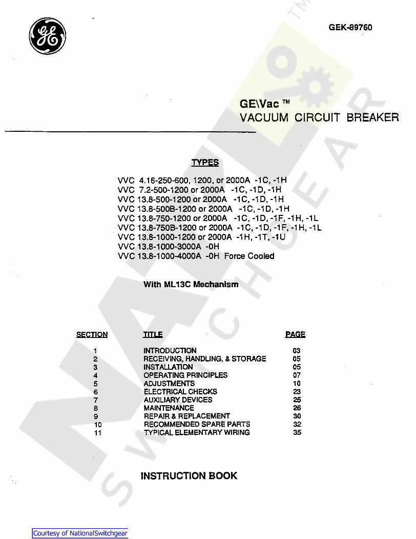
• SECTION 1 2 3 4 5 6 7 8 9 10 11 GEK-89760 GE\Vac™ VACUUM CIRCUIT BREAKER TYPES VVC 4.16-250-600, 1200, or2000A -1C, -1H VVC 7.2-500-1200 or2000A -1C, -10, -1H VVC 13.8-500-1200 or2000A -1C, -10, -1H WC 13.8-5008-1200 or 2000A -1C, -10, -1 H WC 13.8-750-1200 or 2000A -1 C, -1 D, -1 F, -1 H, -1 L VVC 13.8-7508-1200 or 2000A -1 C, -10, -1 F, -1 H, -1 L VVC 13.8-1000-1200 or 2000A -1 H, -1T, -1 U VVC 13.8-1000-3000A -OH VVC 13.8-1000-4000A -OH Force Cooled With ML 13C Mechanism IIIl£ EAaE INTRODUCTION 03 RECEIVING, HANDLING, & STORAGE 05 INSTALLATION 05 OPERATING PRINCIPLES 07 ADJUSTMENTS 10 ELECTRICAL CHECKS 23 AUXILIARY DEVICES 25 MAINTENANCE 26 REPAIR & REPLACEMENT 30 RECOMMENDED SPARE PARTS 32 TYPICAL ELEMENTARY WIRING 35 INSTRUCTION BOOK
Transcript of Vac™ VACUUM CIRCUIT BREAKER - docs.natlswgr.com · ge.nae vacuum circuit breaker gek-89760 + i ....
•
SECTION
1 2 3 4 5 6 7 8 9 10 11
GEK-89760
GE\Vac™ VACUUM CIRCUIT BREAKER
TYPES
VVC 4.16-250-600, 1200, or2000A -1C, -1H VVC 7.2-500-1200 or2000A -1C, -10, -1H VVC 13.8-500-1200 or2000A -1C, -10, -1H WC 13.8-5008-1200 or 2000A -1C, -10, -1 H WC 13.8-750-1200 or 2000A -1 C, -1 D, -1 F, -1 H, -1 L VVC 13.8-7508-1200 or 2000A -1 C, -10, -1 F, -1 H, -1 L VVC 13.8-1000-1200 or 2000A -1 H, -1T, -1 U VVC 13.8-1000-3000A -OH VVC 13.8-1000-4000A -OH Force Cooled
With ML 13C Mechanism
IIIl£ EAaE
INTRODUCTION 03 RECEIVING, HANDLING, & STORAGE 05 INSTALLATION 05 OPERATING PRINCIPLES 07 ADJUSTMENTS 10 ELECTRICAL CHECKS 23 AUXILIARY DEVICES 25 MAINTENANCE 26 REPAIR & REPLACEMENT 30 RECOMMENDED SPARE PARTS 32 TYPICAL ELEMENTARY WIRING 35
INSTRUCTION BOOK
Courtesy of NationalSwitchgear.com
GE.Nae VACUUM CIRCUIT BREAKER GEK-89760
+ I
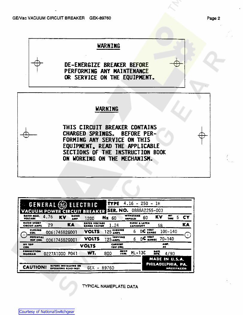
WARNING
DE-ENERGIZE BREAKER BEFORE PERFORMING ANY MAINTENANCE CR SERVICE ON THE EQUIPMENT.
WARNING
THIS CIRCUIT BREAKER CONTAINS CHARGED SPRINGS. BEFORE PERFORMING ANY SERVICE ON THIS EQUIPMENT, READ THE APPLICABLE SECTIONS OF THE INSTRUCTION BOOK ON WORKING ON THE MECHANISM.
· GE. N .ER AL @ ELECT RI C VACUUM POW!R CIRCUIT BREAKER
TYPE 4.16 - 250 - lH
SER. NO. 0888A2255-003 UllD Mila. 4 7 6 KV H11D ¥0UAOI • AMP. 1200 Hz 60
WRKSIAND 60 IMPUUI KV ::, 5 CY
•&llD SllDaf 29 KA Cl8CURAM"I. ~
e&llD VOl.1&01 l 24 ...... f&C1Da •
VOLTS 125 CLOSINO •-s. ~o:tNO 0061745826001 0 .-011N11AL fttl'COU 00617 45826001 VOLTS
UY telf' COil VOLTS CUHllll
HIPCOIL
CONNICflCMC .. aoaa• 0227A1000 P041 YIT • 800 ~:
CAUTION I arroa1 tNUALLINO OD CWHATING HAD tNS1. GEK - 89760
ClOSI & LAICll CAPAD"n'f
6 DC ::.101
58 KA 100-140
6 oC ::;.. 70-140 0
ML-13C
AW. AC
MAb£ IN U.S.A. PHILADELPHIA, PA.
HP0227AS>>o
TYPICAL NAMEPLATE DATA
Page2
Courtesy of NationalSwitchgear.com
GE/Vac VACUUM CIRCUIT BREAKER GEK-89760 Page 3
1. INTRODUCTION
1.1 SCOPE The GE/Vac Vacuum Circuit Breaker is a removable and interchangeable interrupting element for use in vertical lift metalclad switchgear and provides protection and control of electrical apparatus and power systems. This instruction book provides information needed by the user to properly check out, install, and maintain the GENac Circuit Breaker. It does not proport to cover all details or variations in equipment nor to provide for every possible contingency to be met in connection with installation, operation, or maintenance. Should further information be desired or should particular problems arise which are not covered sufficiently for the purchaser's purposes, the matter should be referred to the General Electric Company. To the extent required, applicable ANSI, IEEE and NEMA Standards are met. No such assurance is given with respect to local codes and ordinances because they vary greatly.
1.2 SAFETY . Each user has the responsibility to instruct all personnel associated with this equipment on all safety precautions which must be observed. The following are recommendations to be considered in a user's safety program. These recommendations are not intended to supplant the user's responsibility for devising a complete safety program and shall not be considered as such. They are rather, suggestions, to cover the most important aspects of personnel safety related to circuit breakers. GE neither condones nor assumes any responsibility for user practices which deviate from these recommendations.
1. All personnel associated with installation, operation, and maintenance of power circuit breakers should be thoroughly instructed and supervised regarding the power equipment with which they are working. Instruction books should be closely studied and followed.
2. Maintenance programs must be well planned and carried out consistent with both customer experience and manufacturer's recommendations. Good maintenance is essential to breaker reliability and safety.
3. Local environment and breaker application must be considered in such programs, including such variables as ambient temperatures, actual continuous current, number of operations, type of interrupting duty, and any unusual local condition such as corrosive atmosphere or vermin problems.
4. DO NOT WORK ON AN ENERGIZED BREAKER. IF WORK HAS TO BE PERFORMED ON THE BREAKER, TAKE IT OUT OF SERVICE AND REMOVE IT FROM THE METALCLAD SWITCHGEAR.
· 5. DO NOT WORK ON ANY PART OF THE BREAKER WITH THE TEST COUPLER ENGAGED.
6. All spring charged mechanisms related to a breaker must be serviced only by skilled and knowledgeable personnel capable of gagging or releasing each spring load in a controlled manner. PARTICULAR CARE MUST BE EXERCISED TO KEEP PERSONNEL CLEAR OF MECHANISMS WHICH ARE TO BE OPERATED OR RELEASED. Information on construction of such mechanisms is provided in this instruction book.
7. Operational tests and checks should be made on a breaker after maintenance, before it is returned to service, to ensure that it is capable of operating properly. The extent of such tests and checks should be-consistent with the level of maintenance performed.
8. If maintenance on the GE/Vac breaker is being performed to an extended schedule, it is recommended that the Vacuum Interrupter Integrity Test (Section 6.3) be performed whenever the breaker is removed from the metalclad switchgear and it has been more than one year since the last vacuum interrupter integrity test.
9. Refer to Instruction Book GEH-1802 for a description of the procedure to insert a GE/Vac breaker into the metalclad switchgear. All personnel associated with the installation and operation of the power circuit breakers should be thoroughly instructed on the interlock systems which interface between the circuit breaker and switchgear. NEVER TRY TO DEFEAT OR BY-PASS AN INTERLOCK.
Courtesy of NationalSwitchgear.com

GE/Vac VACUUM CIRCUIT BREAKER GEK-89760 Page4
1.3 GENERAL GE/Vac circuit breakers are interchangeable with breakers having positive type interlocks and single (16 point) secondary disconnect couplers. A double coupler breaker, designated by -10, is available in certain ratings for use in older type switchgear; however, the switchgear must be modified to accommodate this breaker.
The letter designation at the end of the model number given on the nameplate indicates the type switchgear in which the breaker can be used and the type mechanism it will replace. (See Table I)
GE/Vac breakers are designed and tested in accordance with applicable industry standards as shown in Table II. The nameplate describes specific breaker rating and control requirements. The application of a breaker must be such that its voltage, ament, and interrupting rating are never exceeded.
Proper installation and maintenarice are necessary to insure continued satisfactory operation of the breaker. The following instructions provide information normally required for placing the breaker in service and for maintaining satisfactory operation.
TABLE I. DESCRIPTION OF LEITER DESIGNATION
I I BREAKER I TYPE OF I I LETTER RATlNG SWITCHGEAR TYPE OF MECHANISM
·1H ,.1&250 M2l6 ML·t1 or ML·13 7.2-500 M36 ML·t1 or ML-13 13.MOO 1136 ML·11 orML·13 13.1-750 M3llHN ML·11 orML·13
·1C ,.1&-250 M2l6 MS.13 7.2-alO 111311 MS-13 13.MOO 11136 MS.13 13.a.750 M3llHN MS-13
·1L 13.8-750 M36H ML·11 or ML-13
·1F 13.8-750 M36H MS.13
.Qf, 1aa.1000 ·1H
M3&MH ML-12 or ML-13
·1T 13.1-1000 M36H MS.13
·1U 13.a.1000 M3llH ML·11, 12or 13
4i 13.8-1000 .M31H! ML·12 or ML·13 FmmCODl9d
-10 7.2-alO .. ~ Airy MS type. 13.8-500 M3SY 13.8-750
TABLE II. SYMMETRICAL BASIS OF RATING, PER ANSI C37.06-1987
VDLTA81£ C:OllTHUOUS S""'!TUCAL CLOSE A11D MAllMIM RAllGE CultaDT 5HDRT•CHCU%T ltrnRRUPTZll8 LATCH
GEIVAC VOL TAU FACTOR AT 60 Hz CunltlT CAPUILJTY CAPASJLJTY TYPE KV, - IC AMPs, - ICA, - ICA, - KA
nc 4.16-2so 4.76 1.24 1200,2000 29 36 51
nc 7.2-500 8.ZS 1.ZS 1200,2000 33 41 " nc 13.8-500 15.0 1.30 1200,2000 18 23 37 nc 13.8-500.e 15.0 1.30 1200,2000 18 23 58
nc 13.8-750 15.0 l.30 1200,2000 28 36 58 YVC 13.8-7506 15.0 1.30 1200,2000 28 36 77
YVC 13.8-1000 15.0 1.30 1200,2000,3000 37 41 77
Courtesy of NationalSwitchgear.com

GE/Vac VACUUM CIRCUIT BREAKER GEK-89760 Pages
2. RECEIVING, HANDLING, AND STORAGE
2.1 RECEIVING Each breaker is carefully inspected and packed for shipment. Immediately upon receipt of the breaker, an examination should be made for any shipping damage. If damage or rough handling is evident, a claim should be filed immediately with the transportation company and the nearest General Electric Sales Office should be notified.
2.2 HANDLING It is expected that due care will be exercised during the unpacking and installation of the breaker so that no damage will occur from careless or rough handling, or from exposure to humidity, moisture or dirt. Loose parts associated with the breakers are sometimes included in the same crate. Check all parts against the packing list to be sure that no parts have been overlooked.
2.3 STORAGE It is recommended that the breaker be put into service immediately in its permanent location. If this is not possible, the following precautions must be taken to insure the proper storage of the breaker.
1. The breaker should be carefully protected against humidity and condensation. Preferably, store tt in a wann dry room. Breakers for outdoor metalclad switchgear should be stored in the equipment only when power is available and the heaters are in operation, to prevent condensation.
2. The breaker should be stored in a clean location, free from corrosive gases, or fumes. Particular care should be taken to protect the equipment from moisture and cement dust, as this combination has a very corrosive effect on many parts.
3. Unplated surfaces of rollers, latches, and other such parts, should be coated with grease to prevent rusting.
If the breaker is stored for any length of time, it should be inspected periodically to see that rusting has not started. Should the breaker be stored under unfavorable atmospheric conditions, it should be cleaned, dried out, and tested before being placed into service.
3. INSTALLATION
3.1 PREINSTALLATION CHECKOUT Before the initial installation of the GE/Vac circuit breaker in the metalclad switchgear, inspect and check for proper operation and adjustment as follows.
1. Check the breaker nameplate to see that the breaker rating meets the intended application.
2. Remove the shipping wires and open the breaker as described in section 3.2.
3. Check that both the closing spring and opening spring have been discharged.
4. Perform a slow closing operation and make mechanical checks per section 3.3.
5. Perform electrical checks per section 3.4.
6. Check the position of the erosion indicator per section 5.8.
WARNING: DO NOT WORK ON EITHER THE BREAKER OR MECHANISM UNLESS THE CLOSING SPRING AND THE OPENING SPRING HAVE BEEN DISCHARGED. THIS PRECAUTION IS REQUIRED TO PREVENT ACCIDENTAL CLOSING OR TRIPPING. ANYONE WORKING ON THE CIRCUIT BREAKER SHOULD BE FAMILIAR WITH THE DEVICE AS DESCRIBED IN THIS INSTRUCTION BOOK AND SHOULD BE COGNIZANT OF ALL SAFETY PRECAUTIONS. DO NOT WORK ON ANY PART OF THE BREAKER WITH THE TEST COUPLER ENGAGED.
Courtesy of NationalSwitchgear.com
GENac VACUUM CIRCUIT BREAKER GEK-89760 Page6
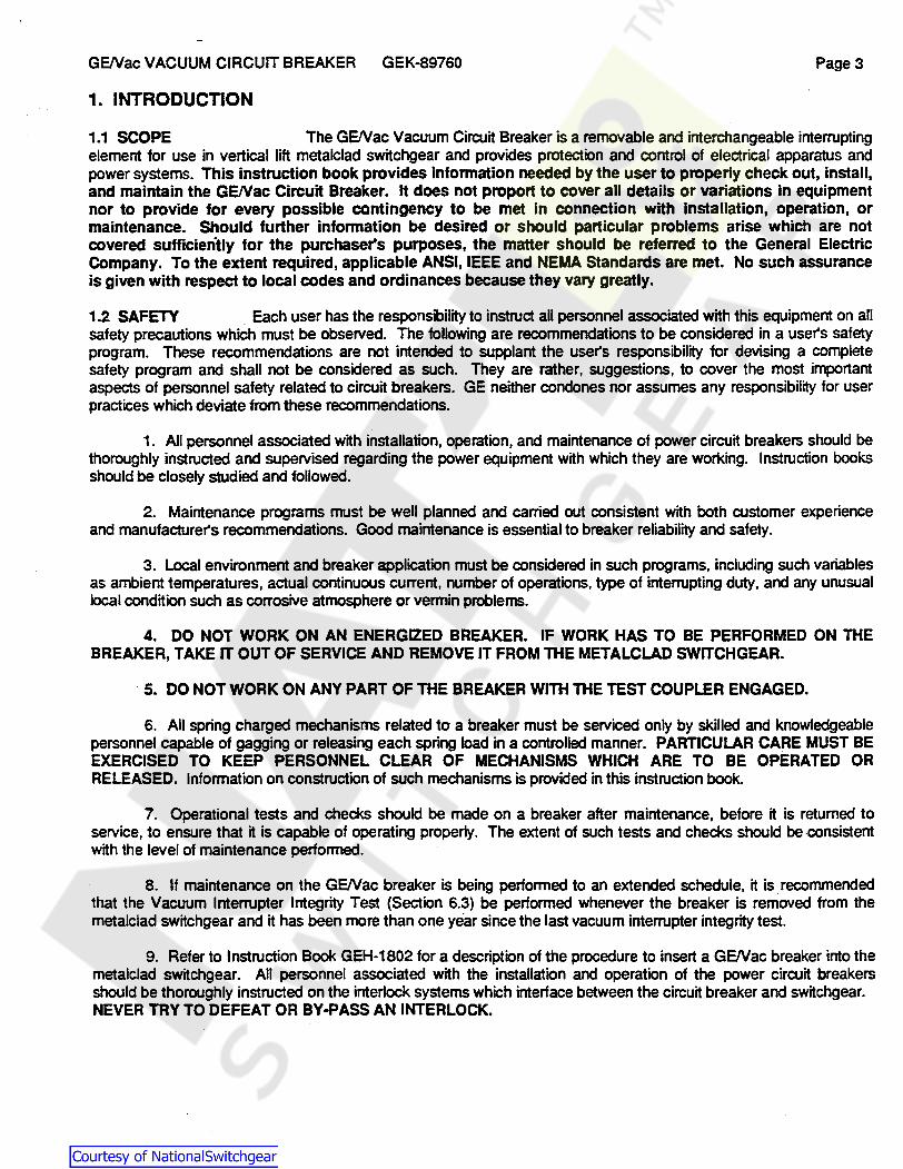
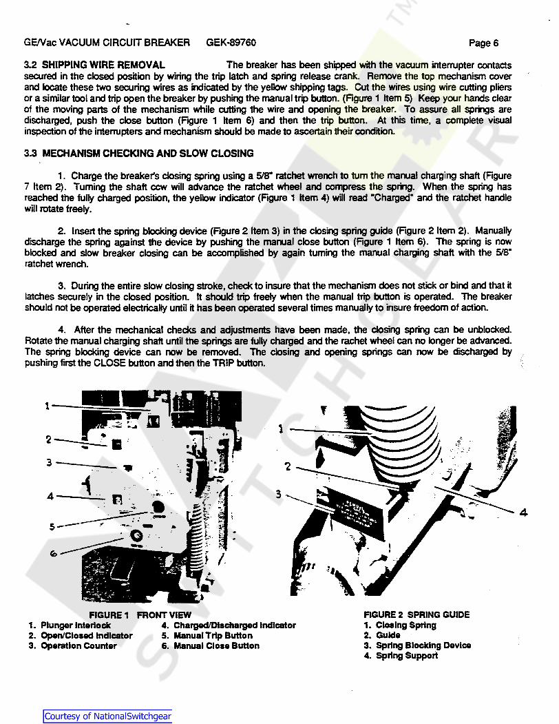
3.2 SHIPPING WIRE REMOVAL The breaker has been shipped with the vacuum interrupter contacts secured in the closed position by wiring the trip latch and spring release crank. Remove the top mechanism cover and locate these two securing wires as indicated by the yellow shipping tags. Cut the wires using wire cutting pliers or a similar tool and trip open the breaker by pushing the manual trip button. (Figure 1 Item 5) Keep your hands clear of the moving parts of the mechanism while cutting the wire and opening the breaker. To assure all springs are discharged, push the close button (Figure 1 Item 6) and then the trip button. At this time, a complete visual inspection of the interrupters and mechanism should be made to ascertain their condition.
3.3 MECHANISM CHECKING AND SLOW CLOSING
1. Charge the breaker's closing spring using a 51a• ratchet wrench to tum the manual charging shaft (Figure 7 Item 2). Turning the shaft ccw wm advance the ratchet wheel and compress the spring. When the spring has reached the fully charged position, the yellow indicator (Figure 1 Item 4) will read ·charged" and the ratchet handle will rotate freely.
2. Insert the spring blocking device (Figure 2 Item 3) in the closing spring guide (Figure 2 Item 2). Manually discharge the spring against the device by pushing the manual close button (Figure 1 Item 6). The spring is now blocked and slow breaker closing can be accomplished by again turning the manual charging shaft with the 518" ratchet wrench.
3. During the entire slow closing stroke, check to insure that the mechanism does not stick or bind and that it latches securely in the closed position. It should trip freely when the manual trip button is operated. The breaker should not be operated electrically until it has been operated several times manually to insure freedom of action.
4. After the mechanical checks and adjustments have been made, the closing spring can be unblocked. Rotate the manual charging shaft until the springs are fully charged and the rachet wheel can no longer be advanced. The spring blocking device can now be removed. The closing and opening springs can now be discharged by pushing first the CLOSE button and then the TRIP button.
t
3----- ..
4_1_ ... F-\ -_ -<~. • •.
····~·-· ~ :.··-· s ------ .... ·-···.~ . - • . 0:. "~--.
FIGURE 1 FRONT VIEW FIGURE 2 SPRING GUIDE 1. Plunger Interlock 4. Charged/Discharged Indicator 1. Closing Spring 2. Open/Closed Indicator 5. Manual Trip Button 2. Gulde 3. Operation Counter 6. Manual Close Button 3. Spring Blocking Device
4. Spring Support
Courtesy of NationalSwitchgear.com
GE/Vac VACUUM CIRCUIT BREAKER GEK-89760 Page7
3.4 ELECTRICAL CHECKING
1. Attach the test coupler to the breaker and operate electrically several times. Check the interrupter gap and wipe per section 5.5. Check the control voltage as described in section 6.1.
2. Perform the vacuum interrupter integrity test described in section 6.3.
4. OPERATING PRINCIPLES
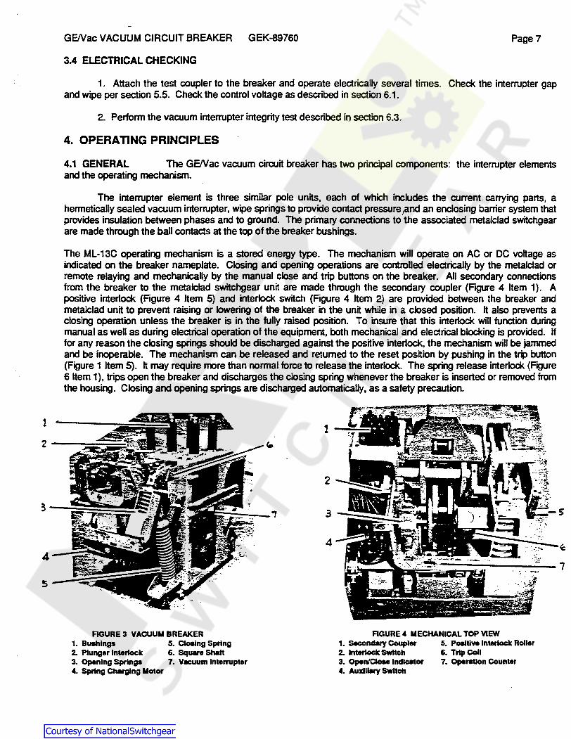
4.1 GENERAL The GE/Vac vacuum circuit breaker has two principal components: the interrupter elements and the operating mechanism.
The interrupter element is three similar pole units, each of which includes the current carrying parts, a hermetically sealed vacuum interrupter, wipe springs to provide contact pressure 1and an enclosing barrier system that provides insulation between phases and to ground. The primary connections to the associated metalclad switchgear are made through the ball contacts at the top of the breaker bushings.
The ML-13C operating mechanism is a stored energy type. The mechanism will operate on AC or DC voltage as indicated on the breaker nameplate. Closing and opening operations are controlled electrically by the metalclad or remote relaying and mechanically by the manual close and trip buttons on the breaker. All secondary connections from the breaker to the metalclad switchgear unit are made through the secondary coupler (Figure 4 Item 1). A positive interlock (Figure 4 Item 5) and interlock switch (Figure 4 Item 2) are provided between the breaker and metalclad unit to prevent raising or lowering of the breaker in the unit while in a closed position. It also prevents a closing operation unless the breaker is in the fully raised position. To insure that this interlock will function during manual as well as during electrical operation of the equipment, both mechanical and electrical blocking is provided. If for any reason the closing springs should be discharged against the positive interlock, the mechanism will be jammed and be inoperable. The mechanism can be released and returned to the reset position by pushing in the trip button (Figure 1 Item 5). It may require more than normal force to release the interlock. The spring release interlock (Figure 6 Item 1), trips open the breaker and discharges the closing spring whenever the breaker is inserted or removed from the housing. Closing and opening springs are discharged automatically, as a safety precaution.
FIGURE 3 VACUUM BREAKER FIGURE 4 MECHANICAL TOP VIEW 1. Bushings 5. Closing Spring 1. Secondary Coupler 5. Positive Interlock Roller 2. Plunger Interlock 6. Square Shalt 2. Interlock Switch 6. Trip Coil 3. Opening Springs 7. Vecuum lntenupter 3. Open/Cloee Indicator 7. Operation Counter 4. Spring Charging Motor 4. Auxiliary Switch
Courtesy of NationalSwitchgear.com

GE/Vac VACUUM CIRCUIT BREAKER GEK-89760 Pages
4.2 PLUNGER INTERLOCK A plunger interlock {Figure 1 Item 1) can be provided to operate a stationary auxiliary switch and/or a rod interlock mounted in the metalclad switchgear unit.
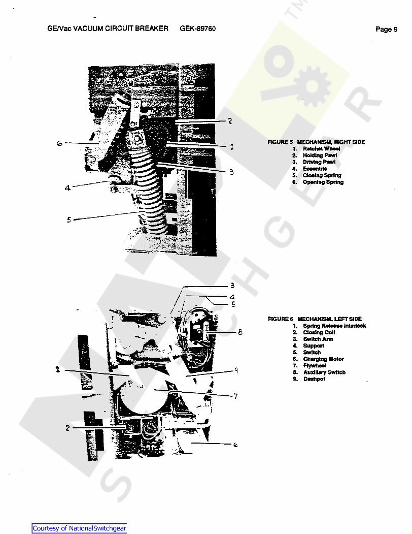
4.3 SPRING CHARGING The ML-13C mechanism has a high speed gear motor that compresses a closing spring through the action of an eccentric, pawl, and ratchet assembly. The rotary action of the motor (Figure 6 Item 6) is converted to a straight stroke pumping action through the eccentric (Figure 5 Item 4) that carries a spring loaded driving pawl (Figure 5 Item 3). The pawl advances the ratchet wheel (Figure 5 Item 1) only a few degrees each stroke where it is held in position by the latching pawl {Figure 5 Item 2). When the ratchet wheel has been rotated approximately 180 degrees, the closing spring will be fully compressed. As the ratchet wheel continues to rotate, tlie spring load will shift over center and atte"l)t to discharge. After only a few degrees of rotation, the closing roller (Figure 8 Item 6) will engage the closing latch (Figure 8 Item 8) and the compressed spring will be held until a closing operation is required. During the last few degrees of the ratchet wheel rotation, the motor and relay switches (Figure 8 Item 7) are released and the driving pawl is on a smooth portion of the ratchet wheel. This allows the motor and driving mechanism to coast to a natural stop expending all residual energy.
The closing spring may be charged manually if control voltage is not available. A 518" ratchet wrench must be used to rotate the manual charging shaft continuously in a ccw direction until the yellow indicator reads "Charged" and the ratchet handle is free. The use of the ratchet handle provides for maximum safety in the event that control power is suddenly restored without warning. In this event, the motor will take over again and continue to charge the spring. Do not use anything but a ratchet wrench if electrical control power can be restored.
4.4 CLOSING OPERATION The breaker is closed by energizing the closing coil (Figure 6 Item 2) or by pressing the manual close button (Figure 1 Item 6). In either case, the closing latch rotates to release the energy of the closing spring which powers the cam (Figure 9 Item 7) that closes the breaker through a simple linkage that remains trip-free at all times. A monitoring switch (Figure 8 Item 13) and power switch (Figure 8 Item 7) control the operation of the spring charging motor.
4.5 OPENING OPERATION The breaker is opened by energizing the trip coil (Figure 4 Item 6) or by f;/ pushing the manual trip button (Figure 1 Item 5). In each method the trip latch {Figure 9 Item 14) is rotated permitting the operating mechanism to collapse. The energy stored in the opening spring is released to open the breaker. During the last part of the opening stroke, the dashpot (Figure 9 Item 5) is engaged. It functions to reduce contact bounce by absorbing excess system energy. During this operation, the trip coil circuit is deenergized and upon completion of the opening operation, the operating mechanism is returned to its reset position, ready for closing.
4.6 TRIP FREE OPERATION If the trip coil circuit is energized while the breaker is closing, the trip plunger.will move the trip latch (Figure 9 Item 14) away from the trip roller {Figure 9 Item .16), causing the mechanism linkage to collapse and the breaker to perform a close-open operation. The closing cam (Figure 9 Item 7) will complete its closirig stroke and the springs will recharge as in a normal closing operation.
Courtesy of NationalSwitchgear.com
GE/Vac VACUUM CIRCUIT BREAKER GEK-89760
1 I -9
-7 ~.
--- .. 1.; .. -2 ~,
1
RGURE 5 MECHANISM, RIGHT SIDE 1. Ratchet Wheel 2. Holding Pawl 3. Driving Pawl ... Eccentric 5. Closing Spring 6. Opening Spring
RGURE 6 MECHANISM, LEFT SIDE 1. Spring A ...... Interlock 2. Closing Coll 3. SWltch Ann 4. support 5. SWltch 6. Charging Motor 7. Flywheel 8. Auxiliary SWltch 9. Dashpot
Page9
Courtesy of NationalSwitchgear.com

GE/Vac VACUUM CIRCUIT BREAKER GEK-89760 Page 10
5. MECHANICAL ADJUSTMENTS AND CHECKS
5.1 GENERAL All adjustments should be checked during periodic inspection and whenever it becomes ·. necessary to repair or replace parts. First, remove the breaker from the metalclad unit, then remove the front mechanism cover, and finally remove the interphase barriers.
WARNING DO NOT WORK ON EITHER BREAKERS OR MECHANISM UNLESS THE CLOSING SPRING AND THE OPENING SPRING HAVE BEEN DISCHARGED. THIS MEASURE IS REQUIRED TO PREVENT ACCIDENTAL CLOSING OR TRIPPING. DO NOT WORK ON ANY PART OF THE BREAKER OR MECHANISM WITH THE TEST COUPLER ENGAGED.
5.2 TRIP LATCH WIPE The wipe of the trip latch (Figure 9 Item 14) on the trip roller (Figure 9 Item 16) should be from .187" to .250·. This can be measured by putting a film of grease on the latch (Figure 9 Item 14), closing the breaker, and then tripping the breaker. The wipe is the width of indentation in the grease. If the latch is resting against the stop pin {Figure 9 Item 15), the wipe should be correct. No adjustment is provided and a visual inspedion is usually all that is required. If this setting is not correct, look for insufficient travel of the trip shaft {Figure 9Item13).
5.3 RELEASE LATCH WIPE The wipe between the release latch (Figure 8 Item 8) and roller (Figure 8 Item 6) should be .187" to .25o·. If re-setting is required, loosen. set, and retighten the adjustment nut and screw (Figure 8Item10), and refer to section 5.10.
5.4 TRIP ARMATURE TRAVEL The trip armature (Figure 9 Item 10) should have .062" to .187" travel plus .032" minimum overtravel before the trip latch (Ftgure 9 Item 14} starts to move. This can be adjusted by moving the trip coil support (Figure 9 Item 8) and/or by adjusting the trip armature screw (Figure 7 Item 3). A locking screw located behind the trip armature screw must first be loosened. Retighten the locking screw after making adjustments.
• - . ~ . .
--- "2
FIGURE 7 LOWER MECHANISM 1. Charging Motor 2. U.nUlll Oulrglng Shaft 3. Trip Ann Screw
I ...... - . FIGURE 8 MECHANISM
4 s
1. Latch Checking SWltch 10. Latch Adjusting Screw 2. SWltct. Cam 11. R..._e Coll Bolts 3. SWltch Striker 12. Closing Latch Spring 4. SWltch SUpport Bolts 13. Latch Monitoring SWltch s. SWltch SUpport 14. SWltch Mounting Br.ckel 6. Closing Latch Roller 15. Closing Coll 7. Power SWltc:hea 16. Qoslng Coll SUpport a. Closing Latch 11. Control Relay 9. Cloelng Latch Shaft
Courtesy of NationalSwitchgear.com

GE/Vac VACUUM CIRCUIT BREAKER GEK-89760
FIGURE 9 ML·13C OPERATING MECHANISM (SHOWN WITH BREAKER CLOSED)
1. Crank 2. Dahpot Coupling 3. Square Shaft 4. Center Crank 5. Dashpot 6. Prop 7. Cem 8. Trip Coll support
9. TrlpColl 10. Armature 11. Trip Crank 12. Closing Roller 13. Trip Shaft 14. Trip Latch 1.5. Stop Pin 16. Trip Roller
17. Clevis 18. Pin 19. Check Nut 20. Adjustment Plate 21. Buffer 22. ·Spring Support 23. Outer Spring 24. Inner Spring
'l DASHPOT 1 1 i;y I z~ lOPENING '-1;-I ~4- ~4 I SPRING
r-x ll 3
4 11 ii 4 .1 11
2 lh . .fl-lfH"'l-- 18
5 r I I
20 21
23 24 25
25. Rod 26. Sliding Plate 1:1. Pin 28. Operating Crank 29. Flywheel ao. cam Wheel 31. Nut Plate 32. Spring Block
'-x ~Y z-i VIEW Z-Z
FRONT VIEW OF MECH
5
4 p::."9 I I i I
·-~ r--· I
i--__,,10 --11
1-~~~-12
13
14 15
ji i 16 Ii 1. ~ ·· ·It lL·-·-·-·-. -·-·- _J; o: -·-·--·..__ .. __ ._.. L..
VIEW Y-Y
Page 11
Courtesy of NationalSwitchgear.com

GE/Vac VACUUM CIRCUIT BREAKER GEK-89760 Page 12
FIGURE 10 TYPICAL SECTION OF 4.16-250 AND 13.8-500 BREAKERS (SHOWN IN OPEN POSmON)
1. R.., Bushing 12. Rnr Insulator 2. Connection Block 13. Wipe cage Auernbly C.tlng 3. SUrge Suppressor (Optional) 14. Wheel 8aM Assembly 4. surge suppressor cable 15. Front Insulator 5. lnterphaae Barrier 16. Wipe Spring 6. V11euum Interrupter 17. Low9r Barrier Gulde 7. Gulde 18. Wipe/Gap Adjustment Nut 8. ContllCt Finger Cluster 19. Connection Bar 9. lloveble Contact Rod 20. Operating Rod 10. a.mp 21. UpperBarrlerGulde 11. Wnr lncllcator Bolt 22. Front Bushing
4
7
18
ll ___ ~
Courtesy of NationalSwitchgear.com
GE/Vac VACUUM CIRCUIT BREAKER GEK-89760
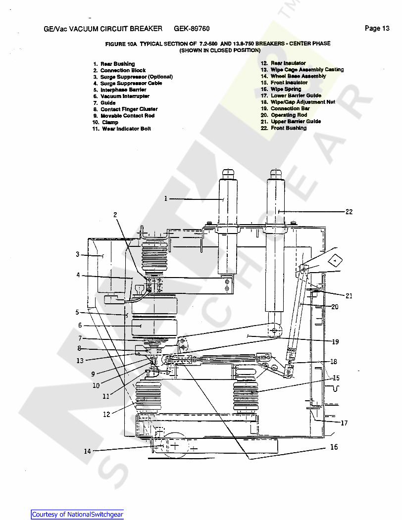
FIGURE 10A TYPICAL SECTION OF 7.2-500 AND 13.8-750 BREAKERS - CENTER PHASE (SHOWN IN CLOSED POSITION)
1. RMI' Bushing 12. Rear Insulator 2. Connection Block 13. Wipe cage Aaembly Casting 3. Surge Suppr ... or (Optional} 14. Wheel a... Assembly 4. Surge Suppresaor Cllble 15. Front Insulator 5. lnterphMe Barrier 16. Wipe Spring 6. V11euum Interrupter 17. Lower Barrier Gulde 7. Gulde 18. Wipe/Gap Adjustment Nut 8. ConlllCt Finger Cluster 19. Connection Bar 9. Movable ConlllCt Rod 20. Operating Rod 10. Clamp 21. Upper Barrier Gulde 11. Wear Indicator Bolt 22. Front Bushing
5-+~-.lr :===:::±=~ 6---~--~-
19
12
16
Page 13
21
Courtesy of NationalSwitchgear.com
GENac VACUUM CIRCUIT BREAKER GEK-89760 Page 14
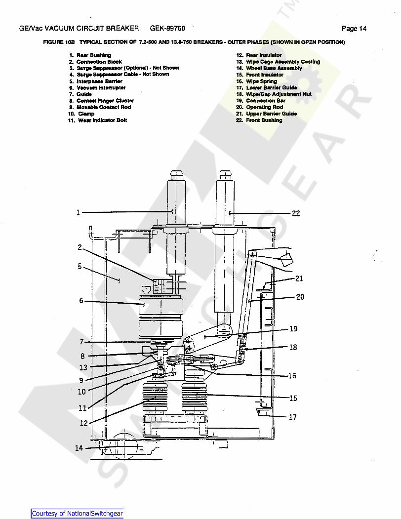
FIGURE 10B TYPICAL SECTION OF 7.2-500 AND 13.8-750 BREAKERS· OUTER PHASES (SHOWN IN OPEN POSITION)
1. A ... Bushing 12. A ... Insulator 2. Connection Block 13. Wipe e.g. Aaernbly Casting 3. SUrge SUppreuor (Optional) - Not Shown 14. WhHI a... Assembly 4. Burge SUppreaor Ceble - Not Shown 15. Front Insulator 5. lnterphMe e.m.r 16. Wipe Spring 6. Vecuum Interrupter 17. Lo .. r Bllrrier Gulde 7. Gulde 18. Wipe/Galp Adjustment Nut a. Contect Finger Cluster 19. Connection Bar 9. Movable Contact Roel 20. Operating Roel 10. Clemp 21. Upper Bllrrier Gulde 11. We• Indicator Bolt 22. Front Bushing
n
2
21
7-l--U--2~~=-J s.J-~---t~
13 .i.-.-4-----::::::--
9 ~~~~~~C..---U.::tl-16 10
' .. ....J
Courtesy of NationalSwitchgear.com
GE/Vac VACUUM CIRCUIT BREAKER GEK-89760 Page 15
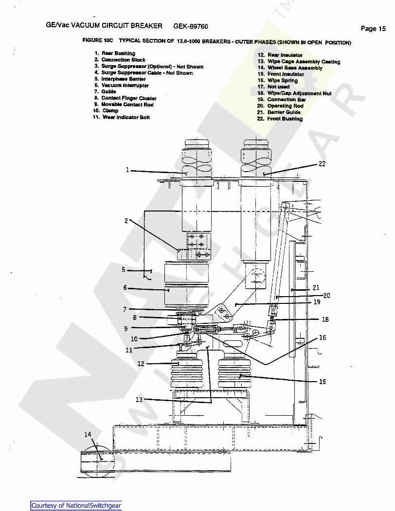
FIGURE 10C TYPICAL SECTION OF 13.8-1000 BREAKERS• OUTER PHASES (SHOWN IN OPEN POSmON)
1. Rur Bushing 12. RNI' Insulator 2. Connection Block 3. SUrge SUppreasor (Optional) • Not Shown 4. SUrge SUppreaor Cable ·Not Shown
13. Wipe Cllge Asaembty Casting 14. Wheel Bae Anembly 15. Front Insulator
5. lnterphase Barrier 6. Vecuum Interrupter 7. Gulde . 8. Contect Finger Cluster
16. Wipe Spring 17. Not used 18. Wipe/Gap Adjustment Nut 19. Connection B•
9. Movable Contect Rod 10. Cl.mp
20. Operating Rod 21. Barrier Gulde
11. We• Indicator Bolt 22. Front Bushing
111
-----1·- --l- --1-----...;
2 I
_I_
14 :- ... - - - - - - --.:-=;~ -, - i- - ·- :r ---------1- - ::-- -::--r --- ------- -1- i- -:
11 I II '.J I ll 11 11 I
i 11 11 11 _..
t. _ - - - - - - - - ~ - - J. - - -~ - - - - - - - - - - ~ - - - - - - - - - - - - - - - - L.] -- ----~------ -----~
Courtesy of NationalSwitchgear.com
GENac VACUUM CIRCUIT BREAKER GEK-89760
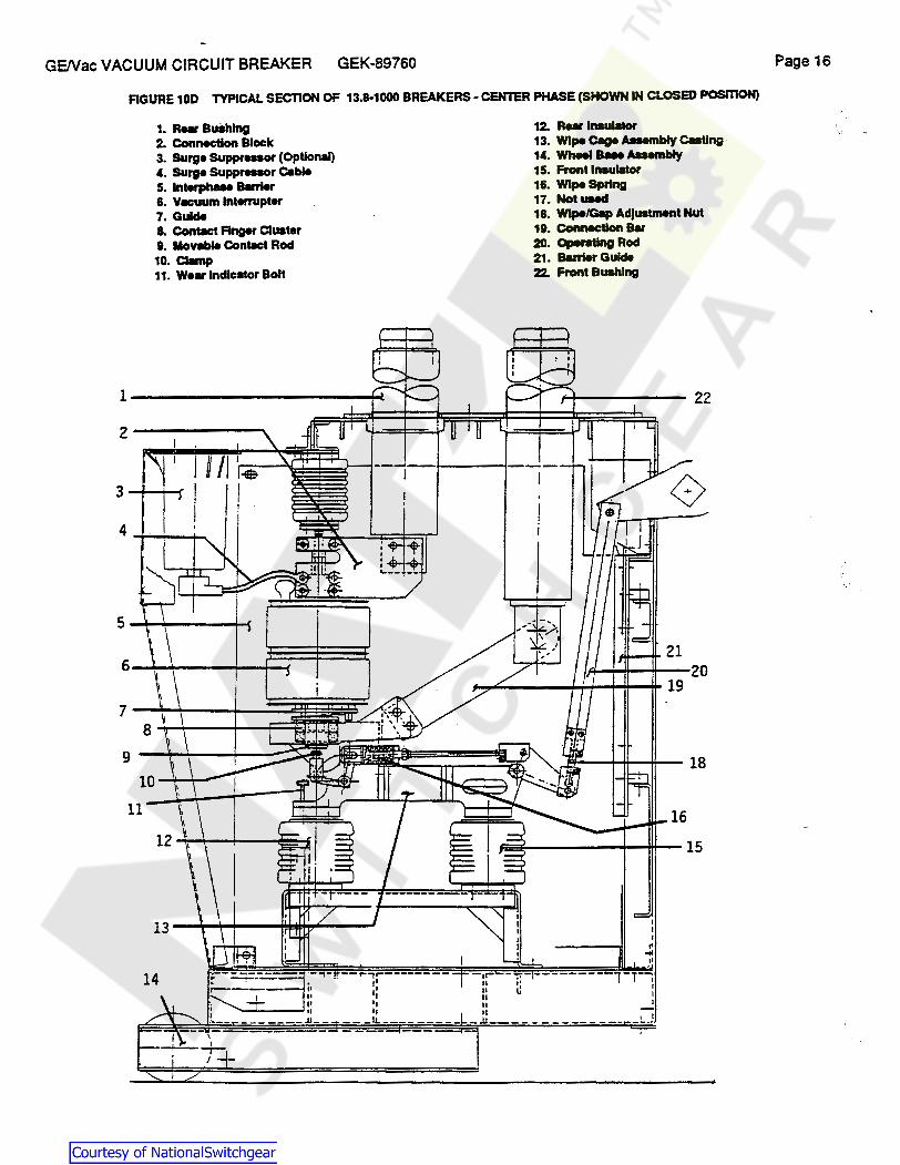
FIGURE 10D TYPICAL SECTION OF 13.8-1000 BREAKERS· CENTER PHASE {SHOWN IN CLOSED POSITION)
1. R ... BuShlng 2. Connection Block 3. surge SUppr ... or {Optional) 4. SUrge SUppreaor Cable 5. lnterpheN Berrier 6. Vecuum Interrupter 7. Gulde 8. Conlllct Finger Cluster 9. llovllble Conlllct Rod 10. Cl.mp 11. Wear Indicator Bolt
2-------.. l /I'•
3-...... - I i
5
6
7
9
10
11
12. RMI' Insulator 13. Wipe C8ge Aaumbly C..Ung 14. Wheel a.. Auembly 15. Front Insulator 16. Wipe Spring 17. Notmed 18. Wipe/Gap Adjuatment Nut 19. Connection Bar 20. Operating Rod 21. Barrier Gulde 22. Front Bushing
I I I ~
-of !'
22
20 19
18
15
·- -.. --r,,...-------- -.r-1• II
1; ;~ l1 II 11 II ---'L---- ----- _JJ ___ - ------ ---
Page 16
Courtesy of NationalSwitchgear.com
GE/Vac VACUUM CIRCUIT BREAKER GEK-89760
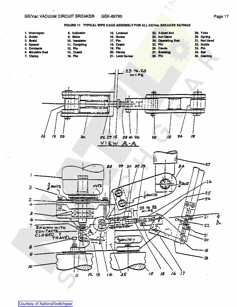
FIGURE 11 TYPICAL WIPE CAGE ASSEMBLY FOR ALLGE/Yac BREAKER RATINGS
1. Interrupter 8. Indicator 2. Gulde 9. Shim 3. Braid 10. Insulator 4. Spacer 11. Coupling 5. Contacts 12. Pin 6. Movable Rod 13. Cnlnk 7. Clamp 14. Pin
1-----'
dl ,....,..
5 ---~:::;;....--; 6--------~~-t____:~ 7 ------....... """'~--
15. Locknut 16. Screw 17. Pin 18. Crank 19. Pin 20. Clevla 21. Lock ScNW
. 2.3 To.2a vvl P£
3316 ~"'
A-A
s 9----J~=~~~~~~=-,
10----_,t._
22. Adjust Nut 23. Not Used 24. Operating Rod 25. Pin 26. Clevis 27. Bushing 28. Pin
18 'Z4-
11
Page 17
29. Yoke 30. Spring 31. Not Used 32. Gulde 33. Pin 34. Bar 35. Casting
19
Courtesy of NationalSwitchgear.com

GE/Vac VACUUM CIRCUIT BREAKER GEK-89760 Page 18
5.5 CONT ACT WIPE AND GAP
1. GENERAL Wipe is the additional compression of the pre-loaded wipe spring (F19ure 11 lterr1 It insures that the vacuum interrupter contacts will stay in the closed position. It also helps to increase the breaker opening speed. Gap is the distance between the two vacuum interrupter contacts when the breaker is open. Wipe and gap are related in such a way that decreasing the wipe increases the gap and increasing the wipe decreases the gap. These two adjustments must be coordinated to bring both to within the required settings simultaneously.
2. MEASUREMENTS With the breaker open, mark the position of the top of the coupling (Figure 13 Item 3) on an index card (Figure 13 Item 6) while the edge of the card is resting on the surface of the casting (Figure 13 Item 5). Mark and label a different card for each phase. Close the breaker and block the opening spring with the opening spring blocking tool (Figure 20 Item 3), to prevent accidental tripping. Mark the position of the top of the coupling (Figure 13 Item 3) on the index card (Figure 13 item 6). The distance between the two marks is the contact gap. Measure the contact gap in this manner on all three phases. While the breaker is still closed and blocked from accidental tripping, measure the wipe distance between the base of the yoke (Figure 11 Item 29) and the locknut (Figure 11 Item 15). A "go - no-go" gauge (Figure 20 Item 1) is available to simplify measuring the wipe. Compare the measured wipe and gap distances with those shown in Table Ill. If distances are outside the limits, make adjustments per the next section.
3. ADJUSTMENT Determine the amount of adjustment required for each phase to bring the wipe and gap within limits. In the closed position, loosen both screws (Figure 11 Item 21 ). Tum the adjusting hex nut (Figure 11 Item 22) clockwise to increase wipe (and reduce gap) and counterclockwise to decrease the wipe (and increase the gap). The adjusting hex nut is designed such that turning the hex 1/6 tum clockwise (as shown in Figure 11), results in a .011" increase in wipe and .011" decrease in gap. If both the wipe and gap cannot be brought within the limits of Table Ill, the total stroke can be adjusted by loosening the check nut (Figure 9 Item 19) and turning the adjusting plate (Figure 9 Item 20) to increase or decrease the total stroke; however, the clearance between the trip latch (Figure 9 Item 14) and the trip roller (Figure 9 Item 16) must not be reduced to less than .005". The final y.rir and gap measurements are based on a normal electrical rather than a manual slow close operation. This is ~ after a manual slow close, the linkage may seat further closed than normal due to frictional effects. In such a Cc.-.._, the "no-go" gauge will go.
FIGURE 12 CLOSING SPRING CHECK AT RATCHET WHEEL
1. Ratchet Wheel 2. Outllr Holding Pawl 3. ~Hole 4. Closing Spring
--- - --- - - --- - ----
Courtesy of NationalSwitchgear.com

GE/Vac VACUUM CIRCUIT BREAKER GEK-89760 Page 19
.-----/
_----3 FIGURE 13 CONTACT GAP MEASUREMENT
1. Movable Operating Rod 2. Clamp 3. Coupling 4. Erosion Indicator Groove 5. C.Sllng 6. Index Card
s
2------1
J-----FIGURE 14 EROSION INDICATOR (BREAKER CLOSED)
1. Movable Operating Rod 2. Clamp 3. Coupling , __ _ 4. Indicator Bolt 5. Locknut 6. Catlng
-
Courtesy of NationalSwitchgear.com

GE/Vac VACUUM CIRCUIT BREAKER GEK-89760 Page20
5.6 CLOSING OPERATION CHECK With the closing spring fully charged, breaker open, and control power disconnected, push the manual close button (Figure 1 Item 6). The breaker has closed proper1y when / between 8 and 14 teeth on the rachet wheel (Figure 12 Item 1) have passed by the outer holding pawl (Figure 12( Item 2). The total tooth count starts from the indexing hole (Figure 12 Item 3). No adjustment should be necessary · but changing the opening spring length could increase or decrease the tooth count. The maximum opening spring length is shown in Table Ill.
5.7 OPENING SPRING LENGTH With the breaker in the open position, the opening spring length is measured from the underside of the top of the spring support (Figure 9 Item 22) to the top of the sliding plate (Figure 9 Item 26). This length should be within the limits given in Table Ill. To increase or decrease the spring length, remove pin (Figure 9 Item 18), pull spring assembly to a vertical position, and tum clevis (Figure 9 Item 17) 1/2 tum at a time.
5.8 CONT ACT EROSION When the vacuum interrupters are new and the breaker is in the closed position, the top of the indicator bolt (Figure 14 Item 4) will line up with the top of the .125" wide groove in the coupling (Figure 14 Item 3).
Contact erosion will occur as the breaker performs its intended service. The wipe must be adjusted within limits as described in Section 5.5 as erosion occurs. When the bottom of the groove reaches the top of the indicator bolt (Figure 14 Item 4), the vacuum interrupter should be replaced. Do not adjust the indicator bolt except when installing a new vacuum interrupter, wipe cage assembly, or operating rod.
5.9 DRIVING PAWL ADJUSTMENT The driving pawl must advance the rachet wheel sufficiently on each stroke to allow the latching pawls to fall into the ratchet teeth. This should be checked with the closing spring load against the driving members. With the mechanism unblocked, hand charge the closing springs with the manual charging wrench until they are slightly more than half charged. Slowly rotate the charging wrench until the driving pawl has traveled through its return stroke and check the maximum clearance between the pawl and the ratchet tooth. Rotate the charging wrench until the driving pawl has advanced the ratchet tooth to its maximum travel. Now; check the clearance between the ratchet tooth and the latching pawl. The clearance should be approximately equal
1
for both the driving and latching pawls and not less than .015" in either case.
If adjustment is required for either pawl, the springs must first be fully charged and blocked. Loosen seven motor support bolts. If the latching pawl clearance is less than .015", move the entire motor assembly to the rear. If the driving pawl clearance is less than .015", move the . motor assembly to the front. Move the motor assembly approximately twice the dimensional increase required at the pawl. Be certain the motor assembly is moved straight forward or rearward and tighten the one bolt on the right side of the mounting frame first to assure proper alignment. After tightening the remaining bolts, the springs should be released and the clearance again checked as described above.
5.1 O RELEASE LATCH MONITORING SWITCH The release latch must be fully reset and the latch monitoring switch (Figure 8 Item 13) operated before the motor will start. When the latch is fully reset, the clearance between the switch striker arm and the switch mounting bracket (Figure 8 Item 14) is .032" or less. Adjust by bending the striker arm.
5.11 MOTOR AND RELAY SWITCHES With the closing springs blocked, rotate the switch cam (Figure 8 Item 2) about 180 degrees, until the switch striker (Figure 8 Item 3) has traveled the maximum amount. At this point the clearance between the striker and the switch support (Figure 8 Item 5) should be .032" or less. Adjust by loosening the switch support mounting bolts (Figure 8 Item 4) and rotating the support.
5.12 INTERLOCK SWITCH WIPE With the positive interlock in the reset, or normal position, the clearance between the interlock switch arm (Figure 6 Item 3) and the switch mounting plate (Figure 6 Item 4) should be .032" or less. Adjust by bending the switch arm.
Courtesy of NationalSwitchgear.com

GENac VACUUM CIRCUIT BREAKER GEK-89760 Page 21
5.13 DASHPOT The dashpot has been adjusted at the factory to constrain contact overtravel and rebound within safe limitations. Adjustment is not required unless it has been removed from the breaker and replaced. If there is any indication of oil leakage, the oil level should be checked with the breaker in the closed position and the opening springs blocked. Remove the fill plug (Figure 15 Item 11) and add GE 050H27 dashpot grade oil to the lower level of the hole. Oashpot action can be checked by using a travel recorder such as a "Cincinnati Recorder". An adapter is available for this purpose. Contact your local GE Sales Office. To obtain less dafl1)ening, screw the piston shaft into the coupling. Adjust one half tum (180 degrees) at a time.
@ .. . ·,. ... . , -. ·' ,, \' ·.. ; / .'
>i' . , ·1---:;0. • .. - ~ 11, 12
VIEW X·X
FIGURE 15 DASHPOT ASSEMBLY
OIL LEVEL WITH
1. Coupling 2. Cover 3. 0 Ring 4. ORlng 5. Cylinder I ........ 81181t
.
\ \
BRKRCLOSED
7. Piston I. Piston Ring I. Waher 10. Groov. Pin 11. Fiii Plug 12. ORlng
BRKR CLOSED
::±::-. ----. ---- ---
l
6
2 3 4
5
6
Courtesy of NationalSwitchgear.com

GE/Vac·VACUUM CIRCUIT BREAKER GEK-89760 Page 22
5.14 SUMMARY OF ADJUSTMENTS AND CHECKS
1. Gap, wipe, and opening spring length. See Table Ill below. 2. Trip latch wipe .187 to .250" 3. Release latch wipe .187 to .250" 4. Closing prop wipe .187 to .375" 5. Latch checking switch contacts make when the gap between the trip latch and the stop is .062" max. 6. Switches - clearance from support .015 to .032". 7. Check all nuts, washers, bolts, cotter pins, and terminal connections for tightness. 8. Inspect all wiring to make sure that no damage has resulted during installation, and test for possible
grounds or short circuits. 9. See that all bearing surfaces of the mechanism have been lubricated. Refer to Section 8.4. 1 o. Operate the breaker slowly with the manual charging wrench and note that there is no excessive binding
or friction and that the breaker can be· moved to the fully opened and fully closed positions. 11. See that any place where the surface of the paint has been damaged is repainted immediately. 12. Check the trip coil plunger and the release coil plunger to see that they move freely. 13. Check that there is no hardware missing.
TABLE Ill GAP, WIPE, AND OPENING SPRING
Opening Spring lnterructer Breaker Type Length Gap Wipe
4.16-250 7.25 TO 7.44" .56 TO .62" .23 TO .28"
13.8-500 7.25 TO 7.44" .56 TO .62" .23 TO .28"
13.8-SOOB 7.25 TO 7.44" .56 TO .62" .23 TO .28"
ALL OTHERS 7.06 TO 7.19" .68 TO .75" .23 TO .28"
FIGURE 16 SCHEMATIC ML·13C MECHANISM
CLOSING SPRING
Courtesy of NationalSwitchgear.com
GE/Vac VACUUM CIRCUIT BREAKER GEK-89760 Page23
6. ELECTRICAL CHECKS
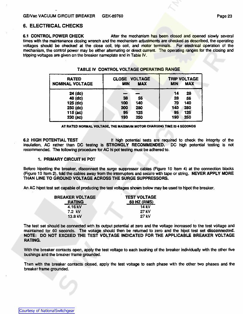
6.1 CONTROL POWER CHECK After the mechanism has been closed and opened slowly several times with the maintenance closing wrench and the mechanism adjustments are checked as described, the operating voltages should be checked at the close coil, trip coil, and motor terminals. For electrical operation of the mechanism, the control power may be either alternating or direct current. The operating ranges for the closing and tripping voltages are given on the breaker nameplate and in Table IV.
TABLE IV CONTROL VOLTAGE OPERATING RANGE
RATED CLOSE VOLTAGE TRIP VOLTAGE NOMINAL VOLTAGE MIN MAX MIN MAX
24 (de) - - 14 28 48 (de) 38 56 28 56
125 (de) 100 140 70 140 250(de) 200 280 140 280 115 (ae) 95 125 95 125 230 (ae) 190 250 190 250
AT RATED NORMAL VOLTAGE, THE MAXIMUM MOTOR CHARGING TIME IS 4 SECONDS
6.2 HIGH POTENTIAL TEST If high potential tests are required to check the integrity of the insulation, AC rather than DC testing is STRONGLY RECOMMENDED. DC high potential testing is not recommended. The following procedure for AC hi pot testing must be adhered to.
1. PRIMARY CIRCUIT HI POT
Before hipotting the breaker, disconnect the surge suppressor cables (Figure 1 O Item 4) at the connection blocks (Figure 10 Item 2), fold the cables away from the interrupters and secure with tape or string. NEVER APPLY MORE THAN LINE TO GROUND VOLTAGE ACROSS THE SURGE SUPPRESSORS.
An AC hipot test set capable of producing the test voltages shown below may be used to hipot the breaker.
BREAKER VOLTAGE RATING 4.16 kV 7.2 kV 13.8 kV
TEST VOLTAGE 60HZ (RMS)
14kV 27kV 27kV
The test set should be connected with its output potential at zero and the voltage increased to the test voltage and maintained for 60 seconds. The voltage should then be returned to zero and the hipot test set disconnected. NOTE: DO NOT EXCEED THE TEST VOLTAGE INDICATED FOR THE APPLICABLE BREAKER VOLTAGE RATING.
With the breaker contacts open, apply the test voltage to each bushing of the breaker individually with the other five bushings and the breaker frame grounded.
Then with the breaker contacts closed, apply the test voltage to each phase with the other two phases and the breaker frame grounded.
Courtesy of NationalSwitchgear.com
GENac VACUUM CIRCUIT BREAKER GEK-89760 Page 24
2. SECONDARY CIRCUIT HI POT
To hipot the breaker secondary circuit, thread a wire through all of the 16 disconnect pins on the secondary coupler {Figure 4 Item 1). Remove the two motor leads from the two point terminal block. Attach the threaded wire to the hipot test set and increase the voltage to 1125 volts {RMS - 60Hz) and maintain for 60 seconds. Reduce the voltage to zero, remove all hipot wires and reconnect the motor leads.
6.3 VACUUM INTERRUPTER INTEGRITY TEST This test will determine the integrity of the vacuum interrupters. It is made with the breaker in the open position and the contact gap properly adjusted.
FOR 4.16 kV BREAKERS, THIS TEST CANNOT BE PERFORMED WHILE THE VACUUM INTERRUPTER IS ASSEMBLED IN THE BREAKER. (Refer to Section 9.2)
The breaker must be in the open position. X-Radiation may be produced if an abnormally high voltage is applied across a pair of electrodes in a vacuum. X-Radiation increases rapidly with an increase in voltage and/or a decrease in contact separation.
CAUTION: DO NOT APPLY VOLTAGE THAT IS HIGHER THAN THE RECOMMENDED VALUE. CONTACT GAP MUST BE WITHIN LIMITS OF TABLE 111 AS DESCRIBED IN SECTION 5.5.
During a high potential or vacuum integrity test, any X-Radiation which may be produced will not be hazardous at a distance safe for high potential testing, if the test is conducted at the recommended voltage and with the specified gap.
Before applying high voltage to the vacuum interrupter, disconnect the surge suppressor cables (Figure 10 Item 4) from the connection block (Figure 10 Item 2}. Fold the cables away from the interrupters and secure with tape or string.
With the breaker open, and the contact gap property adjusted, individually check each interrupter by connecting the -hipot test set "hot" lead to the rear bushing and the ground lead to the front bushing. If the test set has a center point ground, the connections may be made either way. Apply 36kV ac or SOkV de and hold a minimum of five seconds. (Maximum 1 O seconds). If no breakdown occurs, the interrupter is in acceptable condition. If a breakdown occurs, the interrupter should be replaced.
No attempt should be made to compare vacuum interrupters by measuring de leakage current. There is no significant correlation.
After the high potential voltage is removed, discharge any electrical charge that may be retained by touching both ends with a ground stick.
CAUTION: MANY DC HIGH POTENTIAL TEST SETS ARE HALFWAVE RECTIFIERS. THIS TYPE OF HIPOT TESTER MUST NOT BE USED TO TEST VACUUM INTERRUPTERS. THE CAPACITANCE OF THE VACUUM INTERRUPTERS IS VERY LOW AND THE LEAKAGE IN THE RECTIFIER AND ITS DC VOLTAGE MEASURING EQUIPMENT IS SUCH THAT THE PULSE FROM THE HALFWAVE RECTIFIER MAY BE IN THE NEIGHBORHOOD OF 120 kV WHEN THE METER IS ACTUALLY READING 40kV. IN THIS CASE, SOME PERFECTLY GOOD VACUUM INTERRUPTERS CAN SHOW A RELATIVELY HIGH LEAKAGE CURRENT SINCE IT IS THE PEAK VOLTAGE OF 120kV THAT IS PRODUCING ERRONEOUS VACUUM INTERRUPTER LEAKAGE CURRENT. IN ADDITION, ABNORMAL X·RADIATION MAY BE PRODUCED.
An acceptable high potential test set is available from the GE Switchgear Business Department, Burlington Iowa {catalog# 0282A2610P001). The following machines are also acceptable:
Hipotronics Model 860PL, Model 880PL, and Model 7BT60A James G. Biddle Catalog 222060
Courtesy of NationalSwitchgear.com
GE/Vac VACUUM CIRCUIT BREAKER GEK-89760 Page25
6.4 POWER FACTOR TESTING During normal maintenance, some customers perform a routine power factor test. If such a test is performed, be sure to disconnect the surge suppressors. Based on a 60 hertz test voltage of 5kV for 4.16 bushings and 10 kV for 7.2 or 13.8 bushings, the power factor of each bushing should not exceed 5 percent. A bushing with a power factor in excess of 5% when isolated from other components should be replaced.
7. AUXILIARY DEVICES
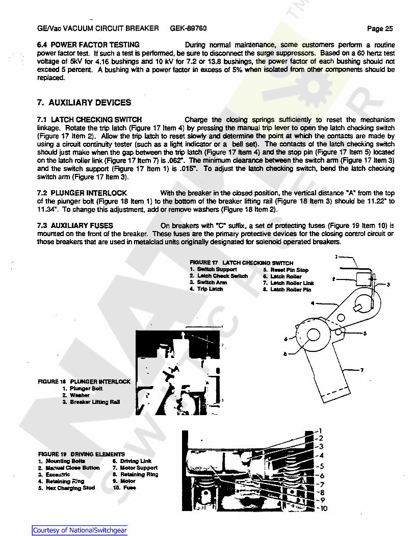
7.1 LATCH CHECKING SWITCH Charge the closing springs sufficiently to reset the mechanism linkage. Rotate the trip latch (Figure 17 Item 4) by pressing the manual trip lever to open the latch checking switch (Figure 17 Item 2). Allow the trip latch to reset slowly and determine the point at which the contacts are made by using a circuit continuity tester (such as a light indicator or a bell set}. The contacts of the latch checking switch should just make when the gap between the trip latch (Figure 17 Item 4) and the stop pin (Figure 17 Item 5) located on the latch roller link (Figure 17 Item 7) is .062". The minimum clearance between the switch arm (Figure 17 Item 3) and the switch support (Figure 17 Item 1) is .015". To adjust the latch checking switch, bend the latch checking switch arm (Figure 17 Item 3).
7.2 PLUNGER INTERLOCK With the breaker in the closed position, the vertical distance ·A· from the top of the plunger bolt (Figure 18 Item 1) to the bottom of the breaker lifting rail (Figure 18 Item 3) should be 11.22" to 11.34". To change this adjustment, add or remove washers (Figure 18 Item 2).
7.3 AUXILIARY FUSES On breakers with ·c· suffix, a set of protecting fuses (Figure 19 Item 10) is mounted on the front of the breaker. These fuses are the primary protective devices for the closing control circuit or those breakers that are used in metalclad units originally designated for solenoid operated breakers.
FIGURE 17 LATCH CHECKING SWITCH 1. Switch Support 5. Raet Pin Stop 2. Latch Check SWhch &. Latch Roller 3. Switch Ann 7. Latch Roller Unk 4. Trip Latch 8. Latch Roller Pin
.. e
FIGURE18 PLUNGERINTERLOCK 1. Plunger Bolt 2. WMher 3. Breaker Uftlng Rall
. , r ~ ~I
/lii. ;l . . . l
'. ·~ i! . ~-·
FIGURE 19 DRMNG ELEMENTS 1. Mounting Bolts I. Driving Unk 2. lla."'lu.I aoae Button 7. Motor Support 3. Eccen'!rlc 8. Retaining Ring 4. Retlllnlng ~!ng 9. Motor 5. Hex Ch#glng Stud 10. FUN
Courtesy of NationalSwitchgear.com
GE/Vac VACUUM CIRCUIT BREAKER · GEK-89760 Page26
7.4 OPTIONAL SURGE SUPPRESSORS GE/Vac Vacuum Circuit Breakers have provision for mounting surge suppressors in the rear of the breaker as shown in Figure 1 O Item 3. Surge suppressors are requirer" on circuits utilizing equipment with low BIL ratings such as motors and dry type transformers. Given thl interchangeability feature of GENac breakers it is recommended that suppressors be used on all breakers that may be interchanged into low BIL applications.
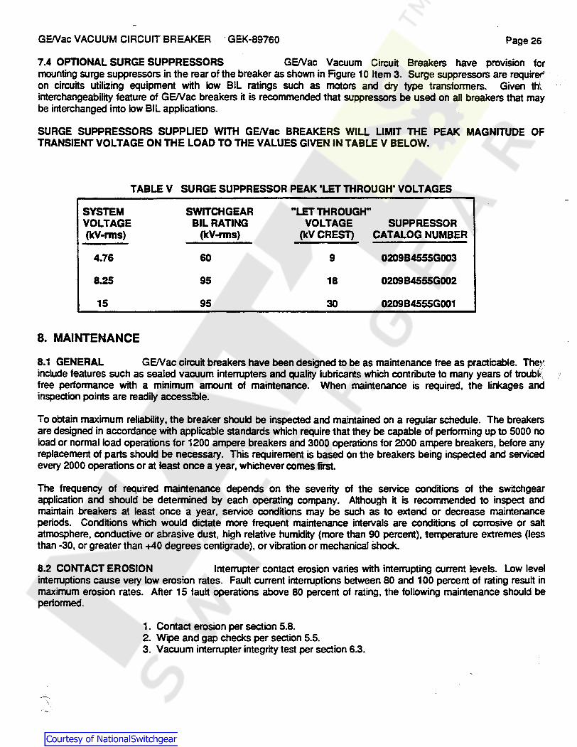
SURGE SUPPRESSORS SUPPLIED WITH GENac BREAKERS WILL LIMIT THE PEAK MAGNITUDE OF TRANSIENT VOLTAGE ON THE LOAD TO THE VALUES GIVEN IN TABLE V BELOW.
TABLEV SURGE SUPPRESSOR PEAK 'LET THROUGH' VOLTAGES
SYSTEM SWITCHGEAR "LET THROUGH" VOLTAGE BIL RATING VOLTAGE SUPPRESSOR (kV-rms) (kV-nns) (kV CREST) CATALOG NUMBER
4.76 60 9 020984555G003
8.25 95 18 020984555G002
15 95 30 020984555G001
8. MAINTENANCE
8.1 GENERAL GE/Vac circuit breakers have been designed to be as maintenance free as practicable. Thev include features such as sealed vacuum interrupters and quality lubricants which contribute to many years of troubl~, free performance with a minimum amount of maintenance. When maintenance is required, the linkages and inspection points are readily accessible.
To obtain maximum reliability, the breaker should be inspected and maintained on a regular schedule. The breakers are designed in accordance with applicable standards which require that they be capable of performing up to 5000 no load or normal load operations for 1200 ampere breakers and 3000 operations for 2000 ampere breakers, before any replacement of parts should be necessary. This requirement is based on the breakers being inspected and serviced every 2000 operations or at least once a year, whichever comes first.
The frequency of required maintenance depends on the severity of the service conditions of the switchgear application and should be determined by each operating company. Although it is recommended to inspect and maintain breakers at least once a year, service conditions may be such as to extend or decrease maintenance periods. Conditions which would dictate more frequent maintenance intervals are conditions of corrosive or salt atmosphere, conductive or abrasive dust, high relative humidity (more than 90 percent), temperature extremes (less than -30, or greater than +40 degrees centigrade), or vibration or mechanical shock.
8.2 CONTACT EROSION Interrupter contact erosion varies with interrupting current levels. Low level interruptions cause very low erosion rates. Fault current interruptions between 80 and 100 percent of rating result in maximum erosion rates. After 15 fault operations above 80 percent of rating, the following maintenance should be performed.
1. Contact erosion per section 5.8. 2. Wipe and gap checks per section 5.5. 3. Vacuum interrupter integrity test per section 6.3.
Courtesy of NationalSwitchgear.com

GENac VACUUM CIRCUIT BREAKER GEK"'89760 Page27
RGURE 20 MAINTENANCE TOOLS (S .. Table VII) 1. Wipe Gauge 2. Closing Spring Block 3. Opening Spring Block 4. Spllnner Wrench 5. Re..anlng Ring Pliers .
1. 3. 2.
5. 4.
WARNING BEFORE ANY MAINTENANCE WORK IS PERFORMED, MAKE CERTAIN THAT ALL CONTROL CIRCUITS ARE DE-ENERGIZED AND THAT THE BREAKER IS REMOVED FROM THE METALCLAD UNIT.
DO NOT WORK ON EITHER BREAKERS OR MECHANISMS UNLESS THE CLOSING SPRING AND OPENING SPRING HAVE BEEN DISCHARGED. THIS MEASURE IS REQUIRED TO PREVENT ACCIDENTAL CLOSING OR TRIPPING. DO NOT WORK ON ANY PART OF THE BREAKER OR MECHANISM WITH THE TEST COUPLER ENGAGED.
8.3 RECOMMENDED MAINTENANCE period.
The following checks should be performed at each maintenance
1. Perform a visual inspection of the breaker. Check for loose or damaged parts. 2. Check the contact erosion indicator and the wipe and gap measurements per section 5.8 and 5.5. 3. Perform the vacuum interrupter integrity test per section 6.3. 4. Check that all stnlcers for operating the interlock switches are adjusted to a clearance ot .015 to
.032" between the striker and the support. 5. Wipe all insulating surfaces clean with a lint free dry cloth or industrial wiper. Clean the barriers,
primary bushing studs, porcelain insulators, operating rods, and the vacuum interrupters. 6. Make a careful inspection of the mechanism to check for loose nuts or bolts and damaged parts.
All cam, roller, and latch surfaces should be inspected for any evidence of damage or excessive wear. Lubricate the mechanism per section 8.4 and perform a slow closing operation to verify that the mechanism operates freely throughout its stroke. Check all control wire terminal connections. Finally, make all the mechanical checks described under Adjustments in section 5.
Courtesy of NationalSwitchgear.com

GE/Vac VACUUM CIRCUIT BREAKER GEK-89760 Page28
8.4 LUBRICATION In order to maintain reliable operations, it is important that all circuit breakers be properly lubricated at all times. Some of the bearings and rolling surfaces utilize a new type of dry lubrication that will , require no maintenance and will last the life of the equipment. Bearings and surfaces listed in Table VI require lubrication. These areas have been property lubricated during assembly at the factory, using the finest grades of lubricants available. However, even the finest oils and greases have a tendency to oxidize with age, as evidenced by hardening and darkening in color. Elimination of the hardened lubricant is essential for the proper operation of the breaker. Also, frequent operation of the breaker causes the lubricant to be forced out from between the bearing surfaces. A simple lubrication will often clear up minor disturbances which might be mistaken for more serious trouble.
A definite lubrication schedule should be set up taking into consideration the frequency of operation of the breaker and local conditions. Until such a schedule is worked out, the breaker should be lubricated in accordance with Table VI, at each periodic inspection and also whenever it is overhauled. It is also recommended that all breakers be operated at regular intervals to insure the user that the equipment is operating freely.
Table VI is divided into two methods of lubrication. The first method outlines the maintenance lubrication which should be performed at the time of periodic maintenance, and requires no disassembly. The second method outlines a lubrication procedure similar to that performed on the breaker at the factory, but should be used only in cases of general overhaul or disassembly for other reasons.
8.5 METHOD OF CLEANING BEARINGS following procedure is recommended.
Whenever cleaning is required, as indicated in Table VI, the
1. SLEEVE BEARINGS The breaker sleeve bearings located in the driving element and the mechanism linkage and frame should be cleaned and relubricated with GE 06A 1SA1 lubricant at general overhaul periods. This includes the bearings in the driving pawl (Figure 5 Item 3), latching pawls, cranks, bearings in the mechanism frame and interconnecting links. Bearings that are pressed into the frame or other mechanism members should not be removed. The main shaft bearings should be removed, cleaned, and lubricated with GE D6A15A1 lubricant at general overhaul periods.
2. ROLLER AND NEEDLE BEARINGS The cam follower (Figure 9 Item 12) and latch roller bearing (Figure 9 Item 16) should be first removed from the mechanism and the inner race disassembled. They should then be placed in a container of clean petroleum solvent or similar cleaner. DO NOT USE CARBON TETRACHLORIDE.
If the grease in the bearings has become badly oxidized, it may be necessary to use alcohol (type used for thinning shellac) to remove it. Ordinarily, by agitating the bearings in the cleaning solution, and using a stiff brush to remove the solid particles, the bearings can be satisfactorily cleaned. Do not handle the bearings with bare hands, as deposits from the skin into the bearings are inductive to corrosion. If the bearings are touched, the contamination can be removed by washing. in alcohol. After the bearings have been thoroughly cleaned, spin them in a clean new light machine oil until the cleaner or solvent is entirely removed. Allow this oil to drain off and then repack them immediately with GE 06A 1SA1 lubricant, being sure all metal parts are greased. The removeable seals should -then be replaced.
NOTE: IF IT BECOMES NECESSARY TO CLEAN THE BEARINGS IN ALCOHOL (SHELLAC THINNER), BE SURE THE ALCOHOL IS PERFECTLY CLEAN, AND DO NOT ALLOW THE BEARINGS TO REMAIN IN THE ALCOHOL MORE THAN A FEW HOURS. IF IT IS DESIRABLE TO LEAVE THE BEARINGS IN THE ALCOHOL FOR A LONGER TIME, AN INHIBITED ALCOHOL SUCH AS IS USED FOR ANTIFREEZE SHOULD BE USED. EVEN THEN THE BEARINGS SHOULD BE REMOVED FROM THE ALCOHOL WITHIN TWENTY-FOUR HOURS. PRECAUTIONS AGAINST THE TOXIC EFFECTS OF THE ALCOHOL MUST BE EXERCISED BY WEARING RUBBER GLOVES AND BY USING ALCOHOL IN A WELL VENTILATED ROOM. EXCESSIVE EXPOSURE TO THE FUMES IS SOMETIMES UNPLEASANT TO PERSONNEL. WASHING THE BEARINGS IN THE LIGHT OIL AND DRAINING SHOULD FOLLOW IMMEDIATELY, THEN APPLY THE LUBRICANT. BEARINGS THAT ARE PRESSED INTO THE FRAME OR OTHER MEMBERS SUCH AS THE BEARINGS. TRIP AND CLOSE SHAFT BEARINGS SHOULD NOT BE REMOVED. AFTER REMOVING THE SHAFT AND INNER RACE, THE BEARING
Courtesy of NationalSwitchgear.com

GENac VACUUM CIRCUIT BREAKER GEK-89760 Page29
CAN USUALLY BE CLEANED SATISFACTORILY WITH PETROLEUM SOLVENT OR A SIMILAR CLEANER AND A STIFF BRUSH. FOLLOW THE PROCEDURE OUTLINED ABOVE USING A LIGHT MACHINE OIL AND GE D6A16A1 LUBRICANT BEFORE REASSEMBLING THE INNER RACE AND SHAFT.
8.6 ROLLING SURFACES The surfaces of the ratchet wheel, cam and pawls are lubricated with a dry molybdenum disulfide coating. This requires no maintenance and should last the life of the breaker.
TABLE VI LUBRICATION
LUBRICATION AT AL TERNA TE PERIOD PARTS MAINTENANCE PERIOD (DISASSEMBLY REQUIRED)
Sleeve bearings - main crank shaft, Light application of Remove Bearings or links, operating rod, opening spring machine oil. clean per instructions and connections, pawls, etc. (Bronze) SAE 20 or SAE 30 apply GE D6A15A1 lubricant
liberally.
Roller and needle bearings Light application of Clean per Instructions and machine oil. SAE 20 or repack with GE D6A15A1 SAE30 lubricant.
Ground surfaces, such as cams, No lubrication required. No lubrication required. ratchet teeth, etc. (Surfaces coated with MOS2)
Ground surfaces such as latches, Wipe clean and apply GE Wipe clean and apply GE rollers, etc •• D6A 15A 1 lubricant. D6A15A1 lubricant.
Silver plated primary disconnect Wipe clean and apply GE Wipe clean and apply GE studs and wipe fingers. D6A 15A 1 lubricant. D6A15A1 lubricant.
Dash pot Check oll level , add oll H Check oll level , add oll H necessary. Fiii to level of necessary.· Fill to level of plug plug hole In side of hole In side of cylinder. Use cylinder. Use GE D50H%7 GE D50H%7 dashpot oil with dashpot oil with the the breaker In the closed breaker In the closed position. position.
Courtesy of NationalSwitchgear.com
GE/Vac VACUUM CIRCUIT BREAKER GEK-89760 Page 30
9. REPAIR AND REPLACEMENT
9.1 GENERAL The following information covers the proper method of removing and replacing· various elements of the breaker. Upon completion of any kind of repair work the mechanical and electrical checks described in Section 5 MUST BE MADE.
9.2 INTERRUPTERS To replace the interrupter, it is first necessary to close the breaker contacts to "K" point (that point where the contacts first touch). ·rhis is done to take the load off the pins to allow easier removal. To close the breaker contacts to the "K" point, follow the slow-close procedure described in Section 3.3, but stop at the "K" point as indicated by a bell set or flashing light set across the front and rear bushings (Figure 1 O Items 22 and 1 ).
1. Disconnect the cables (Figure 1 O Item 4) at the blocks {Figure 1 O Item 2) and remove the complete surge suppressor and support assembly.
2. Remove the two 1/2x13 bolts holding the connection block (Figure 10 Item 2) to the rear bushing.
3. Remove pin (Figure 11 Item 19) after noting the quantity and location of any washers.
4. Remove the 3/4x1 O bolt holding the connection bar (Figure 11 Item 34) to the front bushing {Figure 11 Item 27).
5. Remove the four 3/8x16 bolts holding the casting (Figure 11 Item 35) to the porcelain insulators (Figure 11 Item 10). Be careful to keep the shims used between the casting and insulators in place.
6. Slide the interrupter and wipe cage assembly to the rear and remove to a bench where the assembly can be secured.
7. Remove the clamp (Figure 11 Item 7).
8. Remove the two 3/8x16 bolts holding the guide (Figure 11 Item 2) to the casting (Figure 11 Item 35).
9. Remove the interrupter (Figure 11 Item 1) with its guide (Figure 11 Item 2) attached from the sliding contacts (Figure 11 Item 5) and held in the casting (Figure 11 Item 35). Remove by pulling straight up with a minimum of rocking.
1 O. Disassemble the guide (Figure 11 Item 2) from the interrupter (Figure 11 Item 1) by removing the three nuts.
11 . Remove the two 3/8x16 clamping bolts holding the connection block (Figure 1 o Item 2) to the stationary end of the interrupter (Figure 1 O Item 6).
12. It may be necessary to spread the connection block (Figure 1 O Item 2) in order to reassemble it qn the stationary end of the new interrupter. Do not tighten the two 3/8x16 clamping bolts.
13. Reassemble in the reverse order.
A. Connection block (Figure 10 Item 2). B. Interrupter guide (Figure 11 Item 2). C. Interrupter and guide {Figure 11 Item 1 ). D. Clamp (Figure 11 Item 7) E. Slide assembly into breaker. F. Line connection bar (Figure 11 Item 34) with contact surface. G. Pin and washers {Figure 11 Item 19).
Courtesy of NationalSwitchgear.com
GENac VACUUM CIRCUIT BREAKER GEK-89760 Page31
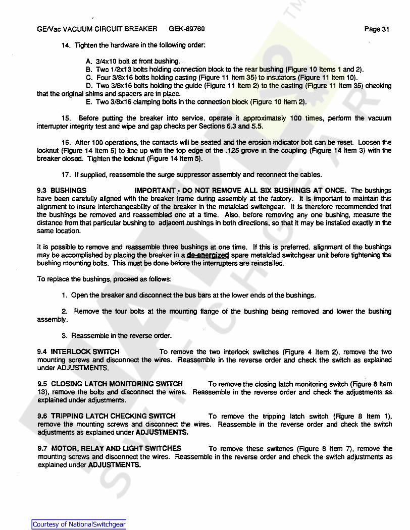
14. Tighten the hardware in the following order:
A. 3/4x1 o bolt at front bushing. B. Two 1/2x13 bolts holding connection block to the rear bushing (Figure 10 Items 1 and 2). C. Four 3/8x16 bolts holding casting (Figure 11 Item 35) to insulators (Figure 11 Item 10). D. Two 3/8x16 bolts holding the guide (Figure 11 Item 2) to the casting (Figure 11 Item 35) checking
that the original shims and spacers are in place. E. Two 3/8x16 clamping bOlts in the connection block (Figure 10 Item 2).
15. Before putting the breaker into service, operate it approximately 100 times, perform the vacuum interrupter integrity test and wipe and gap checks per Sections 6.3 and 5.5.
16. After 100 operations, the contacts will be seated and the erosion indicator bolt can be reset. Loosen the locknut (Figure 14 Item 5) to line up with the top edge of the .125 grove in the coupling {Figure 14 Item 3) with the breaker closed. Tighten the locknut (Figure 14 Item 5).
17. If supplied, reassemble the surge suppressor assembly and reconnect the cables.
9.3 BUSHINGS IMPORTANT.· DO NOT REMOVE ALL SIX BUSHINGS AT ONCE. The bushings have been carefully aligned with the breaker frame during assembly at the factory. It is important to maintain this alignment to insure interchangeability of the breaker in the metalclad switchgear. It is therefore recommended that the bushings be removed and reassembled one at a time. Also, before removing any one bushing, measure the distance from that particular bushing to adjacent bushings in both directions, so that it may be installed exactly in the same location.
It is possible to remove and reassemble three bushings at one time. If this is preferred, alignment of the bushings may be accomplished by placing the breaker in a dHnergized spare metalclad switchgear unit before tightening the bushing mounting bolts. This must be done before the interrupters are reinstalled.
To replace the bushings, proceed as follows:
1. Open the breaker and disconnect the bus bars at the lower ends of the bushings.
2. Remove the four bolts at the mounting flange of the bushing being removed and lower the bushing assembly.
3. Reassemble in the reverse order.
9.4 INTERLOCK SWITCH To remove the two interlock switches (Figure 4 Item 2), remove the two mounting screws and disconnect the wires. Reassemble in the reverse order and check the switch as explained under ADJUSTMENTS.
9.5 CLOSING LATCH MONITORING SWITCH To remove the closing latch monitoring switch (Figure 8 Item 13), remove the bolts and disconnect the wires. Reassemble in the reverse order and check the adjustments as explained under adjustments.
9.6 TRIPPING LATCH CHECKING SWITCH To remove the tripping latch switch (Figure 8 Item 1), remove the mounting screws and disconnect the wires. Reassemble in the reverse order and check the switch adjustments as explained under ADJUSTMENTS.
9.7 MOTOR, RELAY AND LIGHT SWITCHES To remove these switches (Figure 8 Item 7), remove the mounting screws and disconnect the wires. Reassemble in the reverse order and check the switch adjustments as explained under ADJUSTMENTS.
Courtesy of NationalSwitchgear.com

GE/Vac VACUUM CIRCUIT BREAKER GEK-89760 Page32
9.8 CLOSE AND TRIP COILS replaced as follows:
The close coil (Figure 8 Item 15) and the trip coil (Figure 4 Item 6) can be
1. Cut the wires close to the coil.
2. Remove two coil support mounting bolts.
3. When replacing the coil, be sure to note the quantity and position of the fiber spacers on both ends before bolting supports in place.
4. Be certain the armature is centered in the coil and not binding.
5. Butt connect wires and check operation of solenoid electrically and mechanically.
9.9 CHARGING MOTOR To replace the spring charging motor (Figure 6), remove the four mounting bolts from the motor mount. Withdraw the motor from the eccentric. Reassemble in the reverse order and be careful to align the motor so that the motor shaft is free to tum.
1 O. SPARE PARTS
10.1 GENERAL It is recommended that sufficient renewal parts be carried in stock to enable prompt replacement of any worn, broken, or damaged parts. A stock of such parts will save time, expense, and minimize service interruptions caused by breakdowns. When continuous operation is a primary consideration, more spare parts should be carried. The quantity depends upon the severity of the service and the time required to secure replacements. Spare parts which are furnished may not be identical to the original, because parts improvements are made from time to time. The parts which are furnished will be interchangeable. Table VII provides a list of . recommended spare parts. "
10.2 ORDERING INSTRUCTIONS
1. Specify the quantity. part name, and catalog number.
2. If the catalog number is not known, then ~ the equipment TYPE and SER. NO. as shown on the nameplate. Provide the part name and the sub-assembly it is used on. Reference the technical publication number and title used to identify the part. Include the page number, figure and item number.
3. For pricing and availability, contact your local GE representative.
Courtesy of NationalSwitchgear.com
GE/Vac VACUUM CIRCUIT BREAKER GEK-89760 Page 33
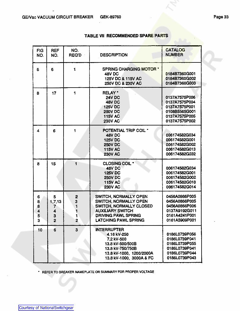
TABLE VII RECOMMENDED SPARE PARTS
FIG REF NO. CATALOG NO. NO. REC'D DESCRIPTION NUMBER
6 6 1 SPRING CHARGING MOTOR * 48VDC 018487360G001 125V DC & 115V AC 018487360G002 250V DC & 230V AC 018487360G003
8 17 1 RELAY* 24VDC 0137A7575P006 48VDC 0137A7575P004
125VDC 0137A7575P001 250VDC 010885565G001 115VAC 0137A7575P005 230VAC 0137A7575P002
4 6 1 POTENTIAL TRIP COIL* 48VDC 006174582G034
125V DC 006174582G001 250VDC 006174582G002 115VAC 006174582G013 230VAC 006174582G032
8 15 1 CLOSING COIL* 48VDC 006174582G034
125V DC 006174582G001 250VDC 006174582G002 115VAC 006174582G010 230VAC 006174582G014
6 5 2 SWITCH, NORMALLY OPEN 0456A0866P005 8 1,7,13 3 SWITCH, NORMALLY OPEN 0456A0866P005 8 7 1 SWITCH, NORMALLY CLOSED 0456A0866P006 4 4 1 AUXILIARY SWITCH 0137A9192G011 5 3 1 DRIVING PAWL SPRING 0161 A4241 P001 3 2 2 LATCHING PAWL SPRING 0161A5909P001
10 6 3 INTERRUPTER 4.16 kV-250 0186L0739P056 7.2kV-500 0186L0739P041
13.8 kV-500/500B 0186L0739P055 13.8 kV-750/750B 0186L0739P041 13.8 kV-1000, 1200/2000A 0186L0739P044 13.8 kV-1000, 3000A & FC 0186L0739P043
• REFER TO BREAKER NAMEPLATE OR SUMMARY FOR PROPER VOLTAGE
Courtesy of NationalSwitchgear.com

GENac VACUUM CIRCUIT BREAKER GEK-89760 Page34
TABLE VII RECOMMENDED SPARE PARTS CONTINUED
FIG REF NO .. CATALOG NO. NO. REC'D DESCRIPTION NUMBER
8 ML-13C MECHANISM BEARING REPLACEMENT KIT 0156C9403G001 GE 06A15A1 GREASE, 4oz TUBE 0183L0907P037 050H27 DASHPOT OIL, 1 GAL 0132A1341008
20 1-5 1 MAINTENANCE TOOL KIT 4.16kV-250 0138D3329G006 ALL OTHER RATINGS 0138D3332G006
10 22 3 FRONT BUSHING * 4.16kV-250 600AMP 0688C0515G006
1200AMP 0845D0123G001 2000AMP 0688C0515G001
7.2 kV-500 1200AMP 0845D0123G003 2000AMP 0958C0683G003
13.8 kV-500 1200AMP 0845D0123G003 2000AMP 0958C0683G003
13.8 kV-750-1H,1C 1200AMP 0845D0123G003 2000AMP 0958C0683G003
13.8 kV-750-1L,1F 1200AMP 0845D0123G004 2000AMP 0265C0188G007
13.8 kV-1000 1200AMP 084500123G004 2000AMP 0265C0188G007 3000AMP 0172C7638G002
13.8 kV-1000 FC 0172C7638G002
10 1 3 REAR BUSHING * 4.16kV-250 600AMP 0688C0516G009
1200AMP 084500124G001 2000AMP 0688C0516G006
7.2 kV-500 1200AMP 0845D0124G003 2000AMP 0958C0684G005
13.8 kV-500 1200AMP 0845D0124G003 2000AMP 0958C0684G005
13.8 kV-750-1H,1C 1200AMP 0845D0124G003 2000AMP 0958C0684G005
13.8 kV-750-1L,1 F 1200AMP 0845D0124G007 2000AMP 0132C2725G001
13.8 kV-1000 1200AMP 0845D0124G007 2000AMP 0132C2725G001 3000AMP 0172C7638G001
13.8 kV-1000 FC 0172C7638G001
* REFER TO BREAKER NAMEPLATE OR SUMMARY FOR PROPER VOLTAGE
Courtesy of NationalSwitchgear.com
GE/Vac VACUUM CIRCUIT BREAKER GEK-89760
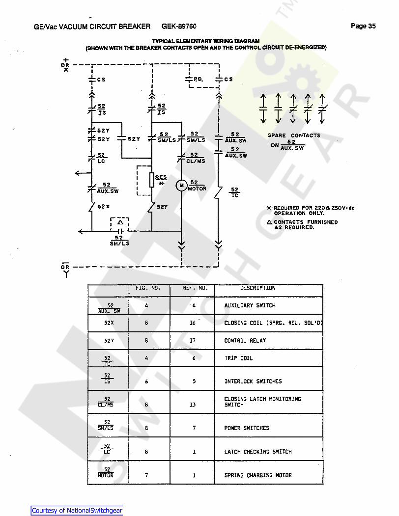
TYPICAL ELEMENTARY WIRING DIAGRAM (SHOWN WITH THE BREAKER CONTACTS OPEN AND THE CONTROL CIRCUIT DE-ENERGIZED)
+ DR---r--------,-----1----1 X I I l I
..L I I ..L ,-cs I :;:P.O. ,_CS I I L.. ----f
A A A
!! IS
52Y 52Y
_g_ LC
52 A'Ux:'S?I
52 IS
52 52Y SiVL.s
r-I I I I L-
52
I~ 52 AUX:Sw
52 'TC
SPARE CONTACTS 52
ON AUX. SW
Page35
52X 52Y *·REQUIRED FOR 220& 250V-dc OPERATION ONLY. r--,
I 6, I
52 SM/LS y y
I I I I
~ I I OR---- - -----------.---- ---' y
fIG. NO. REF. NO.
52 4 -4 i\D~. S~
52X B 16
52Y B 17
52 4 6 """TC-"
52 15 6 5
52 CL/MS B 13
52 SM/LS 8 7
52 L'C 8 l
52 mTOR 7 l
l::. CONTACTS FURNISliED AS REQUIRED.
DESCRIPTION
AUXILIARY SWITCH
CLOSING COIL (SPRG. REL. SOL '0.
CONTROL RELAY
TRIP COIL
INTERLOCK SWITCHES
CLOSING LATCH MONITORING SWITCH
POWER SWITCHES
LATCH CHECKING SWITCH
SPRING CHARGING MOTOR
Courtesy of NationalSwitchgear.com

• -GE Power Delivery & Control
Breaker Plant General Electric Ccmpany 6901 Elmwood Avenue, Philadelphia. PA 19742
GEK-89760 11/90
Courtesy of NationalSwitchgear.com