V2th.0l2.um En3ln2.fU.nQ Station, UlneJial ReJ>ouAc&>...
27
Hydrogeology in the Service of Man, Mémoires of the 18th Congress of the International Association of Hydrogeologists, Cambridge, 1985. HYDROGEOLOGY IN PETROLEUM ENGINEERING C. G. WALL V2th.0l2.um En3ln2.fU.nQ Station, UlneJial ReJ>ouAc&> Engtn22Atng V2.paAim2.nt, Tmp2AÂ.aL ColZzgz o& Scte.nc2. and Technology, London, SW7 2BP ABSTRACT Ground water hydrology and petroleum reservoir engineering have a common basis of differential equations and boundary conditions, only the relative importance of particular problems being different. Solutions to the more important common problems have often been derived independently in the two disciplines, though petroleum reservoir engineering has frequently followed, or 'borrowed' from ground water hydrology. This paper reviews some of the principal problems involved in petroleum reservoir engineering, and their parallels in ground water hydrology. The non-linearity and difficult boundary conditions so often involved in practical problems have led. to an increasing dependence on larger and larger numerical simulations of petroleum reservoirs. The fact that petroleum reservoir engineering (and ground water hydrology) is a geological science, and not predominantly mathematical physics, has sometimes been neglected. The need for the full integration of studies in sedimentary environments, geophysics and reservoir mathematics is emphasized. INTRODUCTION The motion of fluids in porous materials is a phenomenon of interest in many disciplines, amongst them soil science, ground water hydrology, petroleum reservoir engineering and chemical engineering. Developments in one discipline are not always - perhaps not often - followed by practitioners in other disciplines, and each tends to have its own special problems and, sometimes, its own terminology. In considering ground water hydrology in particular, for nearly every problem encountered in petroleum reservoir engineering, a parallel problem, perhaps different in degree, but only rarely different in kind, is encountered in ground water hydraulics. It will be the purpose of this paper to outline, partly by reference to specific examples, the type of problem encountered in optimizing hydrocarbon recoveries, and to draw parallels with analogous problems in ground water hydraulics. The basis of all analytical work in fluid flow in porous media, whatever the discipline, is the empirical transport equation known as Darcy's equation or "Darcy's Law". Attempts have been made to derive Darcy's Law from the Navier-Stokes equation and with suitable - 212 -
Transcript of V2th.0l2.um En3ln2.fU.nQ Station, UlneJial ReJ>ouAc&>...

Hydrogeology in the Service of Man, Mémoires of the 18th Congress of the International Association of Hydrogeologists, Cambridge, 1985.
HYDROGEOLOGY IN PETROLEUM ENGINEERING
C. G. WALL
V2th.0l2.um En3ln2.fU.nQ Station, UlneJial ReJ>ouAc&> Engtn22Atng V2.paAim2.nt, Tmp2AÂ.aL ColZzgz o& Scte.nc2. and Technology, London, SW7 2BP
ABSTRACT Ground water hydrology and petroleum reservoir
engineering have a common basis of differential equations and boundary conditions, only the relative importance of particular problems being different. Solutions to the more important common problems have often been derived independently in the two disciplines, though petroleum reservoir engineering has frequently followed, or 'borrowed' from ground water hydrology.
This paper reviews some of the principal problems involved in petroleum reservoir engineering, and their parallels in ground water hydrology. The non-linearity and difficult boundary conditions so often involved in practical problems have led. to an increasing dependence on larger and larger numerical simulations of petroleum reservoirs. The fact that petroleum reservoir engineering (and ground water hydrology) is a geological science, and not predominantly mathematical physics, has sometimes been neglected. The need for the full integration of studies in sedimentary environments, geophysics and reservoir mathematics is emphasized.
INTRODUCTION The motion of fluids in porous materials is a phenomenon of
interest in many disciplines, amongst them soil science, ground water hydrology, petroleum reservoir engineering and chemical engineering. Developments in one discipline are not always - perhaps not often -followed by practitioners in other disciplines, and each tends to have its own special problems and, sometimes, its own terminology. In considering ground water hydrology in particular, for nearly every problem encountered in petroleum reservoir engineering, a parallel problem, perhaps different in degree, but only rarely different in kind, is encountered in ground water hydraulics.
It will be the purpose of this paper to outline, partly by reference to specific examples, the type of problem encountered in optimizing hydrocarbon recoveries, and to draw parallels with analogous problems in ground water hydraulics.
The basis of all analytical work in fluid flow in porous media, whatever the discipline, is the empirical transport equation known as Darcy's equation or "Darcy's Law". Attempts have been made to derive Darcy's Law from the Navier-Stokes equation and with suitable
- 212 -

approximations - particularly the Stokes approximation that inertial forces are quite negligible compared with viscous resistance terms -equations of the form of Darcy's equation result.
Whether obtained by experiment, by intuition, by analogy with other transport equations, or as an approximate solution to a derivation from fundamental fluid mechanics the essential statement of Darcy's equation is:
flux QC potential gradient
and the original statement of the equation was of the form
q/A = U = - K' §
where the proportionality constant includes terms characteristic of rock properties, fluid properties and acceleration. When the only fluid under consideration is water of constant density and viscosity this formulation is adequate, but in petroleum engineering practice any or all of three fluids with a very wide range of densities and viscosities may be involved,
The most usual formulation then is:
q = U = kj d$m A y "3"T~
where the fluid property and acceleration terms are extracted from the constant of proportionality which is now a property of the porous medium only, provided that the medium is fully saturated with a single fluid. The potential term - a potential per unit mass of fluid is defined by:
dp
-o J Since the usual concern is with volumetric flow rates, a
distinctly less rigorous but convenient form is widely used in engineering practice..
For a fluid of constant density:
_q__.U_.k_ dj_v A j) dL
where <b . is a potential per unit volume and is defined by
$ v = P + pgz
The Darcy equation is only valid when inertial forces are negligible and this is not always the case in petroleum reservoirs, especially in gas reservoirs in the vicinity of high rate wells.
In this case a quadratic equation, usually attributed to Forchheimer, constitutes the basic differential equation when
jj* =oCu W u2
This problem is usually handled non-rigorously in engineering practice simply as an additional steady state well bore pressure drop.
The combination of a transport equation, an equation of state for the flowing fluid, and a conservation statement will result in a
- 213 -

"diffusivity"equation, the form of which will depend on the equation of state for the fluid, and on the co-ordinate system used to define the flow field. For many problems the diffusivity equation can be linearized (it will not usually be an unconditionally linear equation) and the resulting linear partial differential equation may be soluble by transform methods, or by the use of Green's functions for suitably idealized boundary conditions. In the petroleum literature the first solutions of this kind were developed in the 1930's by Hurst and by Muskat, the classic works in this case being the text by Muskat, and the very much later paper by Hurst and van Everdingen (1949). Parallel work in the fields of heat conduction, diffusion and ground water hydrology led to similar solutions.
More recently, the advent of very great computational power and speed has led to an emphasis on numerical methods, and to the use of large and complex "reservoir simulation" studies. This is so even when the basic data available can in no way justify the applications of such methods on the scale employed. Almost only in well test analysis are analytical analyses widely used, and then frequently only as a preliminary to a numerical solution. It does seem to be a characteristic of petroleum reservoir engineering to leave a gap between very simple analytical models and solutions, and large numerical models, any intermediate stage of analytical complexity or difficulty being wholly eschewed.
2. APPLICATIONS
2.1 The PeXnoZem R&i exvoAA. Envihonmewt A petroleum reservoir is a geological body or domain, usually very
poorly defined in its geometrical and physical properties even after development. The reservoir - usually an area of some tens of square kilometres - may be hydraulically continuous with adjacent, or contiguous aquifers, or may be isolated by geologic faults, or by changes in lithology. The reservoirs will occur typically at depths from lOOO metres to 5000 metres, and the cost of a well may range from £500,000 to £10 million, with £3 million to £6 million being a representative range for offshore development wells. These very high costs impose severe constraints on the possible density of drilling, in the use of wells for observation, and even in the permissible duration of well testing procedures.
Recharge of hydrocarbon reservoirs by hydrocarbon is exceptional -gas storage is almost the only example - and exploitation of a reservoir is a single non^-repeatable event.
Whilst the North West Huropean Continental Shelf is of only marginal world significance, the area is of interest since many future developments may occur in areas of similar difficulty '
Examples from that area will form the basis of some of the following discussion.
2.2 Vntn.ole.um RecoveAy The predominant concern of the petroleum reservoir engineer is to
maximise economic recovery of hydrocarbon from the reservoir. The recovery of oil and gas from hydrocarbon reservoirs can be approximated by some very simple equations - though some simply defined factors strictly should be integrated average values of populations of extreme variability and uncertainty.
- 214 -

J , So Box Fractional Recovery = (1 - )
Bo Soi In this equation:
So = average volume fraction of reservoir crude oil in the original reservoir pore volume at abandonment.
Soi = Initial volume fraction of reservoir crude oil in the original reservoir pore volume
Bo,Boi = volume factors for the crude oil at initial and abandonment pressures.
Strictly, corrections are needed for deformation of the pore space but the equation demonstrates the physical requirements for maximising recovery. This requires that So should be reduced to a minimum, and Bo maintained as close as is possible to a maximum. These requirements are met by replacing oil to the maximum extent possible by some other fluid, and by maintaining the reservoir pressure as close as is possible to the saturation pressure of the crude oil. This is naturally subject to economic factors. The available, relatively inexpensive, fluids for oil replacement may be:
water from a contiguous aquifer injected fresh, or sea water gas
GcU, Re.C0U2At/: In this case, the fractional recovery is given by the equation:
Fractional Recovery = i _ Zâ M (V-W) 1 Za Pi V
Where - Pa, Pi = pressures at abandonment and initial conditions respectively
Za, Zi = correction factors for departure from the ideal gas equation
V = initial gas filled pore volume V-W = final gas filled pore volume W = reservoir volume of any influx
Rather different conditions now apply if recovery is to be maximised.
Maximum recovery depends more on minimizing the ratio Pa/Pi than on minimizing ((V-W)/V ) - complete pressure maintenance might result in a recovery factor of 50% of gas in place; pure depletion with no replacement of gas by another fluid might give a recovery factor of 90%.
The optimal requirements of oil reservoirs and gas reservoirs are therefore very different, efficient recovery in oil reservoirs being aided by the presence of active contiguous aquifers or by injection: efficient recovery in gas reservoirs requiring the absence of aquifers or injection.
2.3 MatuAal. kqixl^oXd In 0ÂJL Rtcov&iy. Historically oil reservoir management has involved a period of oil
production under natural mechanisms until sufficient data has been accumulated to form a reasoned view on the efficiency of such mechanisms, and of the probable effects and feasibility of injecting water or gas to replace oil and improve efficiency. This has
- 215 -

depended largely on making inferences about the nature and extent of any apparent aquifer, from the pressure response to offtake from the oil region. With little or no direct information on the aquifer itself - since the drilling of water wells is not an objective -there can be much ambiguity in the interpretation of these data, and it has been argued that hydrocarbon reservoirs are essentially "black boxes" which will not give significant information on their own nature,
The move to difficult offshore environments has changed the nature of reservoir management to some extent. The expense of platform construction is such that late major modifications or additions to facilities and equipment may be prohibitively expensive or physically impossible. It is then desirable to make a decision on whether or not a water flood scheme is to be implemented before any information on reservoir performance, or aquifer activity is available. Supplementation of natural aquifer activity is only possible when it is technically feasible to allow reservoir pressures to fall substantially below the initial pressure. If satisfactory production performance requires that the reservoir pressure should be maintained near to its initial value, then complete reservoir voidage replacement by water will suppress, or at least inhibit, aquifer activity,
In nearly all the larger reservoirs of the North Sea this has been the case - water injection capacity sufficient to replace oil has been installed and is used. Only in smaller, and more marginal reservoirs, or isolated reservoir units within a field are natural depletion mechanisms depended upon oil for recovery.
kqal^dK AnaZyAÂA Zn HydAoaatbon ReAQAVOAJtt,: The analysis and prediction of aquifer response depends upon a mass balance on the hydrocarbon region throughout a history period for which pressure and production data are available. This will give values of any influx term throughout that period, if the hydrocarbon zone properties and the initial hydrocarbon in place are well defined. It is frequently an objective of analysis to attempt to confirm the value of initial hydrocarbon in place as well as to analyse aquifer response. Such an analysis is one of great uncertainty when, as is usually the case, the available data are subject to error (Fig 1).
However it is frequently possible to reconcile the data and fit the aquifer response to an aquifer model - if analytical methods are being used an ideal geometry (radial or linear) must be assigned -when the aquifer functions of Hurst and Van Everdingen (1949) or equivalents can be used. The aquifer model can then be used (cautiously) in further prediction. The use of numerical models can remove the limitations of ideal geometry and can introduce more variablity into aquifer properties, though there is usually little basis, other than the needs of history matching, for assigning variable properties to an aquifer. It is indeed, a common practice to build in only a very limited aquifer into the simulation grid, and to attach to this, arbitrary analytical aquifers as necessary for history matching - the saving substantially in computer time and storage requirements (Fig 2). Figure 3 shows the results of an attempted early analytical approach to aquifer behaviour in a North Sea reservoir, and some values predicted from a fairly sophisticated simulation model. The aquifer system is complex, consisting of two sands in restricted communication and with a number of satellite
- 216 -

hydrocarbon reservoirs which can affect very substantially the compressibility of the aquifer system. Constants for the analytical prediction were based on a single matching point at a very early stage and not thereafter changed. For the variable rate, variable pressure prediction superposition methods are the usual technique used in reservoir engineering and were used in this case.
Reg. 7, hquLfaoji matching uuJk data QAAoft
This is perhaps typical of the reservoir engineers approach to a problem. A theoretical solution to a double aquifer problem, similar to that for a leaky aquifer in hydrology is conceivable. Instead, an equivalent simple aquifer is sought and used for first calculations, and a numerical solution applied when sufficient history is available to justify a model requiring variable properties throughout the domain of interest.
2,4 WelZ Testing and VKQAi>u.h.z AnaluAtA The field of well testing and well test analysis is a further
example of separate development in the fields of ground water hydrology and petroleum reservoir engineering. In general in well testing of oil and gas wells, tests are of rather short duration and pressure build up tests (head recovery tests) have been preferred to drawdown tests. Two principal problems affect drawdown testing in oil and gas reservoirs. The surface volumetric flow rate measured is not the sand face flow rate due to mass transfer effects because of phase changes, and it can be very difficult to stabilise surface oil and gas flow rates sufficiently to assure reasonably constant sand face flow rates - and where minor fluctuations do occur it can be difficult to quantify these fluctuations. Secondly 'head' measurements must be made by pressure gauges operating under adverse conditions•
- 217 -
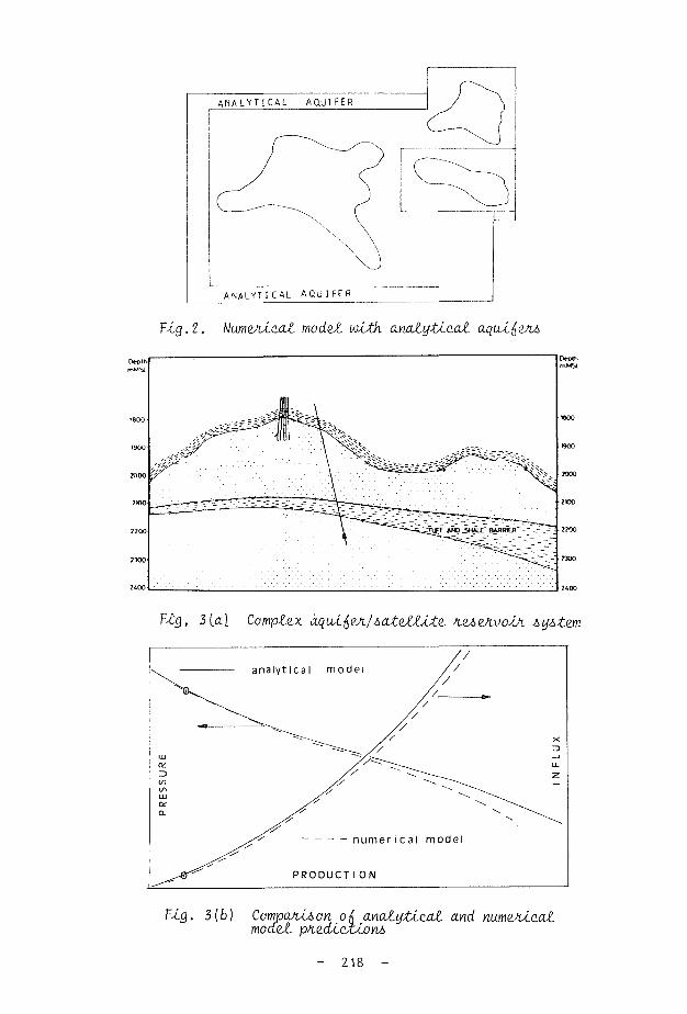
F-ûj.2. Num&vLcal model with analytical aqtui^e/ti,
0*plh mMSl
Vtg, 3[a.\ Complex àquifi&i/Aat&lLite. K&>eA\ioÂJi &y&tem
P R O D U C T I O N
Fxg. 3{b) Companion o{, analytical and numojvLcal model. p/iedicxion6
- 218

In pressure build up testing, minor rate fluctuations have less effect on subsequent build up pressures than on the instantaneous flowxng pressures (and major rate change effects can, at least theoretically, be handled by superposition methods). Additionally recordings of pressure are of rather better quality under the static, quiescent conditions of a shut-in well, than in the extreme turbulence of a two phase flow stream. Even so, when a long test can be carried out, so that rates can be stabilized adequately, the use of the relatively recently developed, high sensitivity, surface recording quartz crystal, or strain, gauges can give good drawdown data for analysis. A major objective of long testing of this kind would be to attempt to define limits to the hydrocarbon accumulation - either fault barriers - the effect of which might be analysed by "method of images" techniques - or possibly faciès changes which might, in a long test lead to a quasi-steady condition (ie, dp/dt constant) being attained during the test. In build-up test analysis, data are usually plotted on semi log or other plots to obtain a straight line segment which can be analysed to yield transmissivities.
Only in recent years have type curve analysis methods featured strongly m the petroleum engineering literature. Many type curves have been developed through numerical radial flow models (well test models) for a variety of conditions. The frequent ambiguity of type curve matching when data are subject to error and uncertainty have limited the practical application of these methods to oil and gas well tests, but are used in preliminary analysis. Derivative methods using the differential of the pressure change/time relationship are currently of interest. Figure 4 illustrates such a type curve
The great majority of the problems or cases outlined in the groundwater literature have direct analogies with petroleum reservoir engineering problems and these are summarized below.
_ J K - H A I J H A N U Î > K 1 N
INFINITE ACTING RESERVOIR WITH D0U8L£ POROSITY BEHAVIOR - Iransient mtofporoaiy flow Theuw o! i nn lycw- cu.ve n Jescr.bwl in Www OJI - Apri! 1984 NEW IYPE CURVES AID ANALYSIS O f FISSURED ZOWE WELL TESTS u» 0
k , l i i t D # C i h i . î U t î q û . ,
„ . . IfHr'.h .1 . 1 0 6 0 H ' ^ U ï Z i i l J U L u m u u h H , '*> . 0OXW95 h f l • " . — l £ p . . . k f „ . - l
A L A G O A J
FOR G A S - P 0 .
i A lOUB Y M PIHAqç
» " T * 2 >* - 0 3 0 ~ » ï q r S . Y» "•
APPROXIMATE END OF UNIT SLOPE
LOG LOG STRAIGHT LINE
DIMENSIONl£SS TIME GROUP 1 0 ' C 0
F-i.g.4. Homal and Vznlvativz Typz CUAVU iinom BouAd&t nt at, 1984)
- 219 -

PaAtialZy Prnzt/mtlng WeÂZi In Petroleum reservoirs, partial completion will be adopted when problems of fluid control - either bottom water or gas cap encroachment - are encountered. This can lead to a coning or cusping problem, the ground water analogy being the coastal aquifer with salt water underlying fresh water. This particular problem will be discussed further in a later section.
MuZtilayeAzd on. St/iatl^zd P.£J>2A.voJJU> The identification of significant stratification and its effect on reservoir flow is of great importance, particularly in multiphase flow and oil displacement.
HoHA.ZOnt.aZ OK. 'CoZttctoK.' WeJLt& Only rarely encountered in the past in petroleum practice, the problems of recovery of heavy viscous oil, and recovery from very thin extensive reservoirs have raised substantial interest in reservoir performance of horizontal wells in recent years.
U&aA Wdll Rami E^ecXi [lnc.lu.dlnQ InzhXlat e^ecXi) oil and gas wells are subject to damage incurred in the drilling and completion process since they are necessarily drilled with overbalanced hydrostatic pressures exerted by a complex and deleterious drilling fluid. The extent of this damage and the removal of damage, require analysis of the effect - known as the 'Skin Effect' in reservoir engineering terms. In gas wells (and occasionally in high rate oil wells) head losses due to inertial effects are common, and since it is standard practice to test gas wells at several flow rates, some analysis of the effect is possible.
This is done by rearrangement of the equation:
A(/p) = Aq + Bq2
and
A(/D) A + Bq
enabling the 'Darcy' effect A, and the non Darcy or inertial effect B, to be isolated when the test data are of good quality. The inertial effect is always treated (legitimately) as a steady state, near well bore, effect or essentially as a rate dependent skin.
Iftte/ifieA.e.nce. TzAtlng Provided that test durations and test responses are adequate, the analysis of the head effect in one well of a period of production (or shut-in) of an offset well can be of interest, particularly since an estimate can be made of storage capacity in the interwell area. Such tests are not common in the petroleum industry, since until the advent of surface recording gauges, the reliability, for long testing, of downhole recording gauges was suspect. Additionally such tests are expensive. There are now few reasons for interference tests not to be carried out - surface recording gauges of high sensitivity can be used, and relatively small pulses or stimuli - imposed as a pattern at the producing well can be identified at the observation well (Fig 5).
The most common "interference" test now made is the pressure record obtained in a newly drilled well in a producing oil field. The repeat formation tester - an electric wire line tool - enables
- 220 -

spot pressures to be taken at any desired point in the sand face of an uncompleted well. This has been of enormous value in identifying layers differentially depleted, by, or isolated from, producing wells giving significant information on continuity and layering in petroleum reservoirs.(Fig 6).
T I M E
Fig. 5. Patit t<H>t poJXahn. and KZAponAt
O R I G I N A L G R A D I E N T
R F T WELL V
R F T WELL 'Y ' X I
SAND A
0 0
zz-z—z-z
SAND 'c
SAND
rZrZ-o
0 'B1
ZJT—1
G
0 0
e
" - T I T _r-_~ - _ - _ J T "
-
~~.
\ \ 1
__
PRESSURE
Vlg. 6. 'Spot' pkQAhuJiz takm with Re,pna£ Vofimation Tut&i
221 -

Weil. Bo-ie StohCLQe Interpretation of very early time data which might be affected by changes in well content (well bore storage) is unusual in high rate wells. Nevertheless when late data is lost or is affected by other factors, analysis of the early time data, affected by storage, may be necessary. A number of approximate methods, and of more exact type curve methods, are used to correct data for such effects.
3. MULTIPLE PHASE PROBLEMS Ground water hydrology is not concerned only with the single
phase; unsaturated flow is a problem of interest above the water table. The motion of air in the unsaturated region is of little interest, and the flow of only one fluid - water - is of interest. The flow of waters of different properties is another problem, but no phase difference involving an interface is involved. These cases, salt water and fresh water, polluted water and unpolluted water, are analogous to some 'miscible' displacements in petroleum reservoirs.
The petroleum engineer will be concerned with the flow of water, oil and gas, and in all cases there will be interfaces between the phases. The existence of the interface in the capillary spaces of the porous medium and the resulting capillary phenomena are crucial elements in the recovery of oil and gas from hydrocarbon reservoirs. The interfacial forces (capillary pressures) are one major factor limiting conventional methods of oil recovery to the apparently low values of 20% *- 60% of the original oil in place.
The second major limiting factor is the heterogeneity of the reservoir, layering and stratification, lateral discontinuity and geometrical irregularity all mitigating against efficient displacement of oil.
3. 7 The Relative. Pe/tmeabttlty Concept Since Darcy's equation has apparently wide validity in represen
ting saturated flow of a single homogenous phase in porous media, it is a natural extension to use a Darcy type equation to describe flow at partial saturations.
The 'true' permeability has been shown to comprise a (dimension) and a dimensionless shape factor, characteristic of the 'shape' of the bounding surfaces. A unique value of permeability requires that the shape factor, and that the 'dimension' should also be unique.
It is intuitive that the presence of one fluid within a pore space will inhibit or prevent the flow of a second fluid as compared with the flow at full saturation. It will be expected that the permeability term for a fluid at partial saturation (the 'effective' permeability) will be a function of that fluid saturation or fraction. For the effective permeability to a phase to be a unique function of saturation for a given medium would require that that saturation would define uniquely the mean dimension and the shape factor for that saturation.
The following conditions must then be met: - that the distribution of fluid within a porous medium
should be defined uniquely by the saturation, and particularly that areas of contact between fluids should be defined only by saturation.
- that the distribution of fluids should not be modified by flow.
- 222 -

that boundary conditions at the fluid interface (shear stress, rate of shear, velocity) should be independent of fluid properties and flow conditions.
A further desirable property of a function would also be that it should be capable of reasonably easy and unambiguous evaluation, either directly by experiment or by indirect derivation from other properties. Effective and relative permeabilities are signally deficient in meeting these conditions so far as oil, water and gas at reservoir conditions are concerned.
In a strongly water wet medium the effective permeability to water is virtuallya single function of water saturation, although the accurate evaluation by experiment can be difficult.
The effective or relative permeability to oil may be a function of both water and gas saturation - it may not be defined uniquely by its own saturation (Fig 7). Also oil permeability is strongly dependent on the direction of saturation change, with substantial hysteresis in the relationship. This need not matter if the direction of saturation change is monotonie, and the history of change known. Situations can arise (eg, gas storage in aquifers) where cycles of saturation occur and the selection of the appropriate permeability is difficult. There may also be a weak dependence of effective permeability on fluid properties and flow conditions.
2 400
Flq. 7. Hui,teJiuiA In Relative. VçjmzabUJXu Relatione
However it is the "wetting preference" - whether a fluid is to be regarded as "wetting" or "non-wetting" with respect to a second fluid - that is dominant.
Conditions of preferential wetting in petroleum reservoirs are not known, and are not always easy to infer. The usual assumption is
13 -

one of water wet rock, but given the variety of mineral surfaces present in clastic formations, and the complex nature of whole crude oil, it would be surprising if conditions of mixed wettability did not occur frequently. Despite all these difficulties in defining both the term itself and in establishing numerical values, the relative permeability concept remains at present the only tractable approach to solving multiphase flow problems in reservoirs, and is used in all petroleum reservoir analysis.
The end point of the relative permeability curves represents the maximum oil recovery possible from a homogenous reservoir consisting of the sample rock. Under the conventional water drive conditions, this is the imbibition end point with a value established by experimental data in the range 15% - 50% of the pore space. Overall reservoir recoveries will be less that those corresponding to permeability end points, because of additional oil entrapment and by-̂ passing in larger scale reservoir heterogeneities.
3,2 Equations ion. flow If no sources or sinks exist in some element of the porous medium,
the general multiphase multidimensional equations for flow can be written:
Vuw =
Vu0 =
K.Krw
K.Kro f VPw - pwgVD }
f~ (VPO -pogVnj
Vug = ~^ g [VPg -/^gVcj
Krw f(Sw); Krg = f(Sg); Kro = f(Sw, Sg)
Sw
Po
Pg
+
-
_
So
Pw
Po
+
=
=
Sg
(PO
(Pc) ow
go
V D is a depth vector directed downwards. In a cartesian co-ordinate system, the permeability will be expressed as a diagonal tensor.
K
K =
X Kv
A general conservation for the flux terms is written
- V ( piVoi) + qi = -T- (Si p± i>)
where qi is a source/sink term for phase i |) = porosity
The petroleum industry usually works in terms of volumes measured at a standard set of conditions and not in terms of mass flow.
'The density for any phase is usually expressed as a density at standard conditions and a volume factor is defined relating the
- 224 -

volume at 'in „situ' conditions to that at surface conditions.
/°-P-T' (V) flow conditions
B — (V) standard conditions
The conservation equations are then written as:-
y,|*K.Kro C^Po - ̂ ogVD)"l + go = £_ (So (fr) lp0Bo J àt Bo
y f K.Krw ( Pw - (KgVD)l + qw = _̂ _ (Sw (f>) \ pwBw J ^t Bw
The equation for gas must also involve a term representing any change in solubility in oil that might occur
^fK.Krg (YPg - ^gVoH +y AcKro Rs (V"Po - ̂ ogVD)l Ifg Bg J Ï» po Bo J
+ qg = i / <4> <S£ So R s ^ Ôt ^ Bg Bo J
where Rs is the solubility of gas in oil and is a function of pressure only at a constant reservoir temperature (standard volumes/ standard volume).
In most real situations, in any one small element of a reservoir, no more than two phases will be flowing simultaneously, and two phase relative permeability relations will be adequate. Even so, the equations are strongly non-linear and solution is difficult. analytical solutions have been developed for only a few cases with idealized boundary conditions. The Buckley-Leverett solution for two phase immiscible one dimensional (or axi-symmetric) flow remains a standard against which most numerical solutions are tested. In large simulator studies, the reservoir elements may be so large that they do encompass regions of the reservoir within which all three phases are flowing. The saturation is extremely non-uniform and the use of block centred average values coupled with conventional relative permeability relations would give erroneous fluxes. An artificial relative permeability function - a pseudo function - which will apply to this hypothetical three phase situation is used to obtain approximately correct fluxes,
The treatment of the gas phase as described is only approximate, since the composition of gas evolved from solution is not constant -the concept of the system as a gas of constant composition soluble in an oil of constant composition is not strictly accurate. Cases where an alternative approach is desirable will be described later.
3.3 UuZtiphaAt flow and ReAeAvoÀA Hzt.eAoge.mity Reservoir heterogeneity is the second major factor limiting the
hydrocarbon recovery from a reservoir. In a stratified reservoir with a high contrast in permeabilities between layers the differential advance of water or gas can be a serious problem. If premature production of water or gas does occur, it will evidently occur in the layers of highest permeability, so that loss in oil productivity can be substantial. The principal reservoir unit of the North Sea tJurassic - the Brent Sand Sequence - is such a heterogeneous series,
- 225 -

and water advance rates of 10 - 15 metres/day compared with the more usual 0.5 metres/day have been observed.
The problem is analogous to the leaky aquifer problem in ground water hydrology with the additional complications of multiphase flow - effects of relative permeability, capillary pressure and gravity being involved. Analytical solution is usually restricted to the segregated layer case, with no cross flow effects; other cases are handled numerically. We are of course, more concerned with correcting the problem than solving the theory, and this has proved difficult. Selective completions, polymer thickening and plugging methods have shown little success,
Even in reservoirs assumed initially to be geologically and physically simple problems have been encountered (Fig 8).
WATER
OVER RIDE
Via c. Radio activa Log showing oveA-uldz In Rt&QJtvoln.
Even with no stratification, there can be severe problems in petroleum reservoirs because of the substantial density differences between oil, gas and water under reservoir conditions. If the vertical (or dip normal) permeability is non zero then some segregation of fluid in the gravitational field will occur. With high permeabilities in the vertical direction highly effective segregation may occur.
This may be a favourable or unfavourable factor for oil recovery depending very much on the specific reservoir geometry. If water or gas tongues are formed and are propagated at higher than average velocities towards producing wells then premature breakthrough and poor recovery is likely.
In steeply dipping reservoirs, or in very thick reservoirs, segregation in the gravitational field may result in water free, or gas free, production being possible for longer than would otherwise
- 226 -
A S W

be the case, and very high recoveries might result. Vertical permeability is a difficult parameter to establish,
depending as it does more on the frequency and extent of thin impermeable shales or cemented layers than on the dip normal permeability of a sand.
Obviously segregation effects can be accentuated or diminished by variation in the horizontal permeability throughout the section.
Figure 9 shows some of the effects that can, and do occur.
viscous fingering
x
Ftg. 9. IhJuiqvJlcUhLtlM* in VAJipta.ceme.nt ?H.oceJ>ieJ
An additional factor frequently observed in the laboratory but of uncertain importance in the field is the phenomenon of viscous fingering. This is a gross inefficiency in displacement when the displaced fluid is very much more viscous than the displacing fluid. Under these conditions the displacement is unstable and the less viscous displacing fluid "fingers" through the viscous displaced fluid. This is not normally a problem in the displacement of a light oil by water, when viscosities under reservoir conditions are similar, but is a problem in 'heavy' oil recovery and potentially in gas displacements of oils, In practice in the field it is difficult to distinguish between effects of stratification and of viscous fingering, and, in gas displacements gravity over-ride seems to be a more important problem than 'viscous' fingering.
Segregated flow conditions can be analysed by relatively simple equations, the difficulty being to determine in any given situation whether a segregated flow model, or the Buckley-Leverett 'dispersed' flow model is more appropriate to a given case.
This raises the central difficulty of modern reservoir engineering T the concept of the appropriate geological model for the reservoir. At present, the computational power available to the engineer
- 227 -

enables a very detailed and complex simulation model to be used. Only rarely is geological detail - correlation of permeable and impermeable layers, trends of porosity and permeability, effective vertical permeability and existence of minor flow barriers - available to create a geologically realistic model.
3.4 CuAp.ing, We.dg-lng and Coning ?tioblom& Perturbation of an interface above or below a producing well has
long been a problem of interest to reservoir engineers and to groundwater hydrologists. In petroleum engineering the potential problems are of gas or water coning or cusping to producing oil wells.
The phenomena is rate sensitive and for sufficiently small rates a stable steadyv-state interface may be formed. Several methods exist for the prediction of the height of small stable cones (Muskat 1937). The limiting, or critical, rate will usually be too low to be of interest in petroleum reservoirs, and the prediction of the time to water or gas breakthrough, and the subsequent ratios of water, or gas, production to oil production become of interest.
For the most part,this three dimensional problem is solved numerically when large perturbations and super-critical rates are involved. However, the desirability of treating wells in a large simulator, through an analytical model relating well bore flows and pressures to "block" flows and pressures, maintains an interest in a suitable analytical solution. Before considering this three dimensional (though axi-symmetric) problem, the slightly simpler two dimensional problems of cusping and wedging will be reviewed.
3.4.1 CuAp-lng and We.dgi.ng ?Kobl<mi> The cusping or fingering problem was solved by a hodographic transform method by Kidder. The solution is mathematically exact for this problem. Bear applied the same technique to the so-called 'wedging' problem - cusping towards a point sink in a vertical plane - in this case an infinite domain.
In the real case of interest in a petroleum reservoir there will be at least one (upper) impermeable boundary and in many cases two (upper and lower) such impermeable boundaries. This leads to difficulty in the hodograph and its transformations, there no longer being one to one correspondence, the mapping taking the form of a Riemann surface.
The problem is of potential practical interest - in hydrology in the performance of horizontal collector wells, and in petroleum in the possible applications of horizontal wells to the production of heavy oil reservoirs underlain by aquifers.
Recently an alternative semi-analytical method has been developed (Gnanathurail which effects the transformation from the unknown free surface onto a known, and soluble, boundary in the new plane, by a perturbation series.
In the real physical plane, (the Z-plane), the shape of the free surface is unknown and is the subject of the study. The usual transformation method is to apply a known transformation (eg, inverse transformation, or Schwarz-Christofel transformation) to obtain a surface in the new plane (J" plane) which is more readily solved. In the present case the form of the sufface in the \ plane is predetermined as one readily solved, and in this case the real surface is mapped point by point on to a unit semicircle, in the plane. The problem is then to find the function which will effect
- 228 -

this transformation. Knowledge of the flow behaviour in the real z-plane is used to determine the form of the required transformation. The mapping relationship is:-
OC
z = 1 1 ( 1 a) ( )
2k+l
a) 2k 2K+1 + ih
and it remains to determine the coefficients a, (a)pK- Continuity of pressure across the interface provides the necessary boundary condition and an integral relationship is found for these coefficients.
In practice the series is truncated (about 9 terms) and the integration for the coefficients is carried out numerically using the trapezoidal rule, using about 40 mesh points in the integration range.
The solution has been extended to the case of a number of point sinks, and to the case of anistropy (Fig 10).
\
soLut ion
L i m i t <ng stabi
high ra te
s \ .
x • ^~~
i t y
VÀ.g. 10. TnanA^ohm ^oh. 'we.dg<Lng' p/ioblm
3.4.2 Tkz Axi-Aymmz&iic Coning Problem Most attempts to solve this problem to date are limited to cases of steady state cones of small height. Numerical methods are valuable when information is required throughout the whole domain, but require extensive computation.
A free boundary problem, such as coning, seeks information principally on the boundary itself and this characteristic is
exploited in the boundary integral equation method. This seeks to integrate the governing differential equations as a first step. The resulting integral equations, which should be a statement of the exact solution to the problem, will involve values of the variables
- 229 -

at the limits of integration, ie on the boundaries of the region. Integration in a closed form may be impossible, but numerical integration is inherently more stable and more accurate than numerical differentiation. Also the computational requirements, involving values only on the boundaries and not throughout the whole domain are modest compared with finite difference or finite element methods. The boundary integral equation method has its bases in Green's second identity. For two functions (u . v) being themselves continuous, and having continuous first and second partial derivatives in a domain D, bounded by a surface S, then
(u<7 v - v Vu) dV = J(u rn - f-) ds
n is unit outward normal from surface S
If the functions are harmonic, the volume integral on the left side of the equation vanishes, and the dimensionality of the problem is reduced by one. Defining u as a function ~& , analytic and harmonic in domain D, and v as a three dimensional Green's function, a solution for J can be obtained by carrying out the surface integration. This does require that >̂ and dj/dn should be known on S which is not, at first the case.
However, if the base point for the Green's function is chosen on the boundary S then
-0Ci <§ (xi, yi, zi) = J < § ^ g ||) ds
where C\ i is a geometrical factor = 2 7V for a smooth boundary. On the boundary either f or ' d<|/dn or some relationship between them will be known for all points on that boundary.
The integral equation can be solved to find whichever variable is unknown, for all points on the «boundary. The general integral equation for the whole domain can then be solved.
The axi-symmetric integral equation becomes:
-oCi $(ri,zi) = f $ i - G ' $ | > rd£ f2 A J *
J g * * (2 A
where G =
;
o 27C d6
/a-b cos 8 o J
= f (K (in))
dG/dn = F (K(m)) ; E (m))
and K (m) and E(m) are the complete elliptic integrals of the first and second kind respectively. These can be represented as accurately as is necessary by polynomials.
In application it has been found convenient to consider the coning problem as the superposition of a basic flow and perturbation flow. The basic flow is taken as that to a line sink in a semi-infinite domain. The perturbation flow due to the cone is solved by the
boundary integral equation method. The necessary numerical integrations and interpolations are then restricted to this element only of the computation.
- 230 -

The r e s u l t s ob ta ined by t h i s procedure (Fig 11) agree wi th e a r l i e r methods for small p e r t u r b a t i o n s of the i n t e r f a c e , and a r e cons idered to be more p r e c i s e than e a r l i e r methods for the l a r g e r p e r t u r b a t i o n s approaching the c r i t i c a l he igh t of the cone
approach t o
c r i t i c a l c o n e h e i g h t
b o u n d a r y i n t e g r a l la rge /smal l t i m e
l i n e a r i z e d so lu t ion
APEX MOVEMENT
CRITICAL HEIGHT
r a d i a l d i s t a n c e T I M E CONING P R O B L E M
tig. 77. C/vUlcal Coning Condition^
3.4.3 Tka Unsteady Stcutz Coning Problem The steady state problem is ultimately trivial in practical petroleum engineering terms Normally nothing will be known about cone formation or cone height until water or gas is produced, and there may then be ambiguity" about the source of the encroaching fluid.
It is the time to breakthrough and the subsequent ratios of water or gas to oil, if coning is the problem, that are of major importance
The problem is more complex than the previous case since the potential throughout the underlying water phase cannot be regarded as constant.
As before, the problem is regarded as one of a basic flow to a line sink in the presence of a no flow boundary, on which is superposed the perturbation flow due to the cone.
Again the integral equations are set up for the axysymmetric case with an equation now for the water domain. Since the normals, and the potential gradients at the surface are inter-related through
and
(n)w = - (n) o
d / o dn dn
- 231 -

the variables for solution can be reduced to the three 0wy' 0oj è ^/ôA As before, points on the surface are first chosen as origins for
the Green's functions, enabling the unknown values throughout the Surface to be found. The values of potential and flow can then be calculated throughout the two domains.
Although the thickness of the water layer seems not to affect significantly the development of the cone up to breakthrough point, the more realistic condition of a finite water thickness and a lower permeable boundary has also been solved.
MODEL POST BREAKTHROUGH P R O D n
Fig. 72. Po&t Bn.zaktkx.oa.gh Vh.oda.cM.on ConcLOU.onA
PoJbt BJie.akthA.OU.gh Btha.vi.OUA. The water fraction or gas to oil ratio to be expected after breakthrough and the rate of development of water cut or gas oil ratio are of substantial interest to the petroleum engineer since these factors can represent an economic limit to oil production.
The true unsteady state behaviour of a post breakthrough condition is difficult to evaluate, not least because the true boundary conditions are not easy to define. SteaSy state approximations have been developed for this period of production, usually on a basis that a limiting water oil ratio corresponding to a constant cone height is attained. The water oil interface is then assumed to be a limiting streamline, and equivalent single phase oil and water systems are defined and analysed.
Some improvement to this model is effected by considering the reduction in permeability in the originally oil occupied cone(Fig 12) but the solution remains an approximate steady state approach.
- 232 -

4, COMPOSITIONAL AND MASS TRANSFER PROBLEMS IN RESERVOIR FLOW There are several situations in petroleum engineering which
involve compositional effects, - that is, the distribution of one or more components between vapour and liquid phases; or, mass transfer effects concerned with the distribution of oil and water between water, miscible and oil phases. These are problems in which the complexity of the phase interactions greatly exceeds the complexity of the flow problem and realistic solutions can be very difficult-to achieve.
The first case is represented typically by condensate and volatile oil reservoirs, where the initial reservoir fluid may be an indeterminate 'dense' phase, near to critical conditions. The second case occurs in surfactant micellar and low interfacial tension 'floods' in which the interfacial forces responsible for oil entrapment are reduced by introducing a surfactant with the flood water. The oil will then partition(possibly in a complex manner) between an oil or oil rich, phase, and an emulsion in water, displaced by water.
Most improved recovery methods will involve difficult problems of physical description, modelling and analysis.
4.1.1 CondtnAoutz and VotcvtiZt QiZ ReAZAvoAJvi Several examples of reservoirs of this type are known in the North Sea and constitute a substantial resource for development in the near future. Condensate reservoirs owe their name to their behaviour of condensing liquids from a vapour or dense phase upon pressure depletion. Because of the relatively low volume fraction of such liquid condensates, their mobility in the porous medium is also very low, and direct recovery by liquid phase flow may be negligible. Since the condensates are rich in heavier, and more valuable, components there is an economic loss proportionately greater than the volumetric loss,
The traditional method of maximising economic recovery, was to 'cycle' the reservoir, returning to the reservoir gas stripped of its heavier components. This maintains reservoir pressure and retards condensation. The economics of cycling depend heavily on the relative sales values of condensate recovered and of gas sales deferred. This is a problem which must be solved prior to development, since one development option will normally preclude others.
Numerical simulation studies which are reasonably physically representative of the real reservoir situation can be difficult to conduct. The accurate representation of the phase behaviour of a condensate system - liquid and vapour volumes densities, viscosities and interfacial tensions - may require the consideration of more than twenty individual components. Simulation studies are then dominated by the phase calculation routines, and only the simplest of reservoir descriptions may be possible. One approach to this problem is the use of a few pseudo-components each representing a group of hydrocarbons (or hydrocarbons plus non-hydrocarbons). Provided that a reasonable set of data are available on the physical properties of a real system such a method can be 'tuned' by regression procedures to give a reasonably high degree of accuracy in gas and liquid production predictions for moderate computer cost. The flow problems themselves in these reservoirs are relatively small -there are minor problems in the effects on permeability of liquid
- 233 -

condensate, but nearly all the problems are of other physical phenomena - the condensation process itself; diffusion and convection processes in mixing of reservoir 'wet' gas and cycled 'dry' gas; revaporisation of condensate by cycled dry gas.
Obviously in numerical modelling, numerical dispersion adds to the problem of handling physical dispersion. However, so long as hydrocarbon gas is displacing hydrocarbon gas, the mixing problem is not dominant, as it would be if a reservoir were to be cycled using an inert gas (eg, nitrogen). Even in this case, in a sand sequence such as the Brent Series, channelling through high permeability layers is a much greater concern.
4.7.2 CaAbon V-Loxido, VAAplac.me.ntb Carbon Dioxide injection is a recovery mechanism involving compositional effects. Dissolving in crude oil, it has a very substantial volume effect. At reservoir conditions it is a dense fluid, and suffers very much less from the gravity over-ride effects characteristic of light gas injection.
Analysis of carbon dioxide injection involves consideration of solubility in formation water, which is always present, as well as in oil, and the effect of carbon dioxide concentration on liquid and gas densities and viscosities must be handled either through an equation of state or through tabulated data. It does however involve only one additional component and so is less complex than the multicomponent problems of condensates and volatile oils.
4,2 ImpKovzd Rucov&iy VKoc^hU, Significant improvement in oil recovery over and above recoveries
obtainable by conventional methods requires a substantial modification of the interface between trapped residual oil and the displacing phase. The conventional representation of the relationship between oil entrapment and interface properties is as shown in Fig 13. - the capillary number being a ratio of viscous forces to capillary forces.
——x£_
1 / ,
& •
1
, d 6
1
1
.0 '
1 I
i d 3
1
r
1
CAPILLARY NUMBER U-M-0
F-uj. 7 3. 1 nfi-uience. ofi CapiLtcuty Uumb&i on Oil RecoveAy
234

It can be seen that changes of several orders of magnitude are necessary to effect a significant change in trapped oil fractions. Interfacial tension can be changed by orders of magnitude either by the use of hydrocarbon solvents, or by surfactants. For convenience the present discussion will concentrate on hydrocarbon miscible displacements, but similar principles are involved in aqueous 'chemical' displacements. The model of a miscible displacement process, is one .in which oil is scavenged by a solvent, accumulating to create a system of oil, displaced by a solvent, itself displaced by some other medium.
There will be diffusion and convective mixing of solvent and oil, and also of solvent and displacing fluid. If excessive mixing occurs, then "attenuation" or "degradation" of the solvent buffer occurs, and miscibility is lost.
The problem is modelled mathematically by combining statements for convective transport and for diffusive transport, to give an equation of the form
ÔC
dt "
+
+
A f D àc , D èc D ôc = ~Si i xx •-— + x y r + xz x— -
ôx \ ôx * dy oz à TD àc D ôc D ô c
fc { ™ Sy + yx fc + yz 5i " i_ R z ࣠+ D z x | c + D | c . ôz \ ôz ôx by
" U x C )
" u c r y J
- u c \ z J
The linear flow case can be solved analytically for a range of boundary conditions, the well known error function complement solution being a reasonable approximation for a variety of boundary conditions. The coefficients Dij are combined diffusion:displacement coefficients and are not easily evaluated independently of experiment. The 'mechanical' or 'convective' component of this term is strongly affected by small scale heterogeneities within a porous medium, although for isotropic media of regular grain size empirical relations have been proposed.
In the fluid systems of interest in petroleum reservoirs, densities and viscosities of oil, solvent and displacing fluid are likely to be markedly different, and viscous fingering and gravity override will affect mixing strongly.
Analytical solutions are therefore of limited interest and applicability outside the laboratory.
Numerical methods allow several of the above difficulties to be handled, but some discretization schemes may introduce numerical dispersion effects of a greater order than the physical dispersion terms. Adopting schemes which minimize the numerical dispersion term may introduce oscillations, or overshoot, into the solution.
Nevertheless numerical simulation, preferably based on comprehensive laboratory study and field pilot studies represent an essential evaluation tool for an area of operations which will be increasingly important in petroleum recovery.
5. GEOLOGICAL INTERPRETATION AND UNCERTAINTY IN PETROLEUM RESERVOIRS Probably the greatest problem in modern reservoir engineering is
that of uncertainty in the properties of the reservoir itself - that is problems of geological interpretation of the reservoir structure
- 235 -

itself and the distribution of properties. Most petroleum reservoirs of potential interest are moderately deeply lying structures which are both complex in their origin, and their subsequent history. Submarine fan structures, deltas, tilted fault blocks, salt dome structures are typical of North Sea reservoirs; frequently there will have been diagenesis of clay minerals, which itself may have been arrested or inhibited by hydrocarbon migration. This can lead to substantial difficulty in assessing average properties of a large (in petroleum terms) area.
The problem is particularly acute in the early appraisal stages, when the major investment development decision must be made on a basis of data from perhaps 4 to 8 appraisal wells. The assignment of reservoir thickness, net to gross ratios, porosity, permeability and water fraction is fraught with uncertainty. The purely static calculation of hydrocarbon in place will involve a Monte Carlo simulation of the expected range of outcomes, and this may be extended to the economic evaluation of the financial outcome.
The dynamic problems of rates of oil or gas recovery, of the incidence and magnitude of water production problems may be attempted by sensitivity analysis, undertaking a series of simulation runs for alternative sets of properties. Geological models of the prognosed sedimentary environment, inter-related with highly detailed seismic surveys will be the basis for such sensitivity studies, Although such studies will predict the outcome if the real reservoir properties conform to a particular prediction, the probability of that particular prediction being the reality of the reservoir remains a highly subjective decision.
In nearly all cases of conventional recovery of oil or gas from reservoirs, the mathematical problems of solution - even the still difficult problem of multiphase flow - are subordinate to this greater problem of accurate reservoir description. Obviously the problem becomes slightly less as development proceeds, but under modern development conditions, options are severely constrained once the development decision has been made, and the density of well spacing is still sparse
In the more difficult cases described - the condensate and volatile oil problems, and the miscible and chemical recovery methods of EOR - the mathematical problems are as difficult as the problem of reservoir description. It is however uncertainty about the reservoir properties, and to a lesser extent, uncertainty about the physics of some of the phenomena involved that are greater inhibiting factors than mathematical difficulties.
The hope for resolution of these difficulties lies in the greater application of fully integrated studies between engineer, geologist and geophysicist. The use of statistical methods in the study of natural variation, and the evaluation of trends is growing.
In petroleum reservoirs, it is permeability anomalies that will have the greatest effect on performance - the existence of channel sands, high permeability layers, vertical permeability variation, permeability barriers etc - and purely statistical techniques have a limited application in this non-random but uncertain environment. Nevertheless, Kriging techniques are now receiving some attention in reservoir evaluation,
- 236 -

CONCLUSIONS For every problem that occurs in groundwater hydrology a parallel
problem exists in petroleum reservoir engineering, and there has been a parallel development in the two sciences throughout the decades. Both disciplines have borrowed solutions from the related fields of heat conduction and diffusion theory, and from each other and have developed their own solutions as the need has arisen.
In the petroleum field, the very substantial variations in densities and viscosities will generally make the equations involved more strongly non-linear than problems involving predominantly water flow. Even so, approximate linearization is possible and analytical solutions derived many decades ago have served the industry well-
In recent years the commercial value of petroleum development, coupled with the great uncertainty of reservoir properties, has led to the extensive use of and dependence upon, large numerical simulator studies. This has meant that theoretical approaches and reviews of very basic concepts and assumptions have been neglected, though many problems remain where more computer power is not the answer
NOMENCLATURE
q
A
K1
h
k
P
M
P
$m
$v(9)
z
a
Volume rate of flow
Gross cross sectional area
normal to flow
'Darcy' constant of proportionality
Fluid head
Permeability
Fluid density
Fluid viscosity
Pressure
Potential/unit mass of fluid
Potential/unit volume of fluid
Elevation above datum
'Darcy' coefficient
'Non-Darcy' coefficient
Fraction of pore volume occupied
by phase 'o'
Volume, at reservoir conditions,of a
standard volume, or mass, of hydrocarbon
Values of S and B at initial conditions o o
Correction factor for non-ideality of
gas (= PV/RT)
3 , L /T
L/T
L 2
L . 3
M/L
M/LT 2
M/LT 2 , 2
L /T . 2
M/LT
L
M/L T
1/L
- 237 -

'Darcy' and 'Non Darcy1 coefficients
for oilfield equations
Normalized dimensionless permeabilities to
oil, water and gas in a multiphase
system
REFERENCES
Bourdet, D., Alagoa, A., Ayoub, J.A. and Pirard, Y.M. 1984. New type curves and analyses of fissured zone well tests. World Oil, April 1984.
Dake, L.p. 1978. Fundamentals of reservoir engineering. Elsevier Scientific Publishing Company, Amsterdam. 443 pp.
Ewing, R.E. 1983. The mathematics of reservoir simulation. SZAM, Philadelphia. 186 pp.
Hurst, W. and Van Everdingen, A.F. 1949. The application of the Laplace transformation to flow problems in reservoirs. Trans A.I.M.E., 186, 305-324.
Liggett, J.A. and Liu, P.L.F. 1983. The boundary integral equation method for porous media flow. George Allen and Unwin, London. 255 pp.
Muskat, M. 193 7. The flow of homogeneous fluid through porous media. McGraw-Hill Book Co. Inc. New York.
Peaceman, D.w. 1977. Fundamentals of numerical reservoir simulation. Elsevier Scientific Publishing Company, Amsterdam. 176 pp.
A, B
K ; K ; ro rw
- 238 -