
V100, V200 & V400 Operation and Maintenance Manualmarking.com.ua/INSTRUKCII/MANUAL...
291
V100, V200 & V400 Maintenance Manual Operation and
Transcript of V100, V200 & V400 Operation and Maintenance Manualmarking.com.ua/INSTRUKCII/MANUAL...

V100, V200 & V400
Maintenance Manual
Operation and

(2) 27864 Issue 1 January 2008
ord Issue 1 January 2008
Amendment Rec

27864 Issue 1 January 2008 (3)
CONTENTS
PART 1 : HEALTH & SAFETY........................................................................5
...........15
...........71
.........163
.........251
APPENDIX B : EASYDESIGN MANUAL ....................................................257
PART 2 : INSTALLATION..................................................................
PART 3 : OPERATION ......................................................................
PART 4 : MAINTENANCE & FAULT FINDING..................................
APPENDIX A :TECHNICAL REFERENCE ........................................

(4) 27864 Issue 1 January 2008
THIS PAGE INTENTIONALLY LEFT BLANK

PART 1 : HEALTH & SAFETY
CONTENTS
Page
.............7
.............9
........... 11
Warning Notices .....................................................................................11
Caution Notices ......................................................................................13
EC DECLARATION OF CONFORMITY ........................................GENERAL SAFETY.......................................................................HAZARD INFORMATION..............................................................
27864 Issue 1January 2008 (5)

HEALTH & SAFETY
THIS PAGE INTENTIONALLY LEFT BLANK
(6) 27864 Issue 1 January 2008

HEALTH & SAFETY
EC DECLARATION OF CONFORMITY (In accordance with ISO/IEC 17050-1)
Objects of the Declaration: V100, V200, V400 Printers. Standard and FHE V-Series Controllers
irectives:
368/EEC, 93/44/EEC,
• 73/23/EEC : Low Voltage Directive as amended by 93/68/EEC
92/31/EEC and 93/68/EEC
c standards section 1: Immunity for residential, commercial and light
nments. rial
of measurement of electromagnetic disturbance dical (ISM) radio frequency equipment.
current emissions (equipment input
in low voltage
• EN 61000-4-3, Radiated electromagnetic field requirements cal fast transient/burst immunity test; Basic EMC publication
• En 61000-4-6, Immunity to conducted disturbances, induced by radio frequency fields. • ENV 50204, 1995 Radiated electromagnetic field from digital radio telephones.
Signed for and on behalf of
Domino UK Limited, Bar Hill, Cambridge (December 2007)
Issuer’s Name: Domino UK Ltd
Issuer’s Address: Bar Hill Cambridge CB23 8TU
The Objects of the declaration described above are in conformity with the requirements of the following D
• 89/392/EEC : Machinery Directive as amended by 91/93/68/EEC and 98/37/EEC
• 89/336/EEC : EMC Directive as amended by
The
• EN 61000
Following Standards have been used to show compliance:
-6-1, 1997: Generiindustrial environments.
• EN 61000-6-2, 1997: Generic standards section 2: Immunity for industrial enviro• EN 61000-6-4, 2001: Generic standards section 4: Emission standard for indust
environments. • FCC part 15 subpart B • EN 55011, 1998+A1+A2: Limits and methods
characteristics of industrial, scientific and me• EN 61000-3-2: 1995+A1+A2, Limits for harmonic
current up to and including 16 A per phase) • EN 61000-3-3: 1995, Limits, limitation of voltage fluctuations and flicker
supply systems for equipment with rated current ≤ 16 A • EN 61000-4-2, Electrostatic discharge requirements
• EN 61000-4-4, Electri• EN 61000-4-5, Surge immunity requirements
27864 Issue 1January 2008 (7)

HEALTH & SAFETY
THIS PAGE INTENTIONALLY LEFT BLANK
(8) 27864 Issue 1 January 2008

HEALTH & SAFETY
p hine Safety Regulations.
a system re points of the source of energy directly earthed, the
t point by
nnected to f the source.
ing no rts of the
ected her supply replaced it
tions rocedures
Failure to do so may invalidate warranty.
y be used for the purpose for which they d and constructed. No parts may be used for
print head.
is powered d present a
azard.
be in nd non
d to all unused connectors to protect against dust and dirt and possible static damage to internal components.
Ensure all reasonable safety precautions have been undertaken. However, please ensure that when working with / or around the machine, every care is taken to avoid potential hazards. ALWAYS take great care around the machine not to slip, trip or fall; especially if the machine is used in areas where the floor may be wet or greasy.
GENERAL SAFETY The roduct is designed to conform to all current Mac
Note: Please read through this section before operating the machine.
This printer is designed for use with the following supply systems that conform to IEC 664 light industrial / domestic installation category II mains supply:
• ‘TN’ (any of following - TN-C, TN-S or TN-C-S) for example; having one or moexposed conductive parts of the installation being connected to thaprotective conductors.
• ‘TT’ for example; a system having one point of the source of energy directly earthed, the exposed conductive parts of the installation being coearth electrodes electrically independent of the earth electrodes o
It is not suitable for connection to an ‘IT’ system for example; a system havdirect connection between live parts and earth, the exposed conductive painstallation being earthed. This therefore excludes any ‘phase to phase’ connsupplies such as may be available in some factories and / or countries. If eitfuse (located on the rear of the Controller, below the supply connector) is must be replaced by a fuse 3.15/6.3AT - 230/115V – 50/60Hz - 300VA. Installation
must only be performed by qualified Domino personnel. For customer installaauthorisation must be obtained from Domino UK Ltd. All relevant Safety Pmust be followed.
The printer and its component parts must onlwere sold, and for which they are designeother functions.
Do not touch the printer or the controller with wet or damp hands.
Do not expose the printer or controller to rain.
Do not run the printer without ribbon material, as this may damage the
ALWAYS disconnect the power to the machine before removing any covers. You must remove the plug from the mains power supply.
DO NOT insert body parts into the print head opening whilst the printeras there is a danger that the mechanism will move without warning ancrushing h
DO NOT operate the machine with any covers removed. ALL covers mustplace using the appropriate number of fasteners. It is essential that electrical aelectrical connector dust covers (provided with the machine) are fitte
27864 Issue 1January 2008 (9)

HEALTH & SAFETY
If non Domino ribbon is used, it is recommended that anti static propertconsidered. Domino U
ies are K Limited cannot guarantee the safety and / or suitability of
lectronic fault causing an unexpected start up of
turer’s safety e specifications as
nic checks
s be replaced (it should last for several years). In the event of Domino for repair. Please
.
’s
and belief esigned only as guidance for
safe handling use, processing, storage, transportation, disposal and release and is not considered a warranty or quality specification. The information relates only to the specific material designated and may not be valid for such material used in combination with any other materials or in any process unless specified in text.
non Domino print ribbon.
Take care, in the unlikely event of an eprinter drive motors, to avoid possible injury.
If a verification scanner is used on this machine, please follow the manufacprocedures. When fitting and / or operating the scanner, follow thstated in the appropriate Laser Safety Standards (IEC825).
Please read the Manufacturers Safety Data Sheet (MSDS) for Isopropanol before using the cleaning kit with any Domino product.
There is a danger of electrical shocks from the electrical outlet. All electromust be performed by qualified personnel.
There is a non replaceable lithium battery mounted on the Industrial PC. Under no circumstances should thifailure, please return the whole control board assembly to note the following:
There is a danger of explosion if the battery is incorrectly replaced
Only Domino recommended replacements must be used.
Used batteries should be disposed of according to the battery manufacturerinstructions.
The information above is correct to the best of our knowledge, information at the date of this publication. The information given is d
(10) 27864 Issue 1 January 2008

HEALTH & SAFETY
HAZARD INFORMATION This section contains important notices. You must read these notices bprinte
efore using the r. The hazard information is prioritised into warning and caution notices as
follows:
g notices denote a potential hazard to the health and safety of users. These e nature of respective hazard and the means by which it can be
Handlin
Warning Notices Warninnotices clearly state thavoided.
g the V200 The Cassette handle is for removing the cassette only.
a crushi
It must not be used as a means of carrying or holding the printer as this may result in the printer becoming detached from the cassette causing
ng hazard.
Airborne particles
Airborne particles and substances are a health hazard. Do not use pressure compressed air for cleaning purposes.
Heating element
high-
your fingers.
The heating element and surrounding area become very hot use. To avoid the risk of burns or damage to the print
head, never touch the heating element area of the print head with
Organic solvents
during
Cleaning fluid contains organic solvents, it is recommended to wear suitable goggles and clothes to avoid contact with the eyes and skin. Avoid inhalation of the vapour. Do not smoke in the presence of the vapour.
27864 Issue 1January 2008 (11)

HEALTH & SAFETY
Lethal voltages
personnel may carry out maintenance work.
Observe all statutory electrical safety codes and practiis necessary to run the printer, disconnect the printmains electrical supply service before removing the cover or
Lethal voltages are present within this equipment wconnected to the mains supply. Only
hen it is trained and authorised
ces. Unless it er from the
attempting any service or repair activity, otherwise death or
Compre
personal injury may result.
ssed air supply
To avoid the risk of injury to personnel or damage to the equipment, do not exceed the flow and pressure specification.
Battery replacement
Replaceable batteries should only be replaced usingthe same type and ra
batteries of ting. Failure to do so may result in an
explosion hazard.
atteries should be disposed of according to the battery
Fuses fire hazard
Used bmanufactures instructions.
To ensure continued protection against the risk of fire, replace fuses with the specified type and rating only.
(12) 27864 Issue 1 January 2008

HEALTH & SAFETY
Caution Notices Cautionary notices denote a potential hazard to the physical integrity ofsoftware but not a danger to personal. Thes
equipment / e notices clearly state the nature of the
hazard and the means by which it can be avoided.
Damag e to Print Head
Changing the print head without setting the new resistance value may cause severe damage to the print head.
Loss o The counter values are not retained when the control box is switched off.
f Counter Data
The counter values are not retained when the control box is switched off.
Equip ment Damage
wh
To avoid the possibility of electric shock hazard and damage to equipment. Do not fit or remove any connector on the printer
ile the printer is switched on.
Cable Routing To avoid damage to the cables or equipment, ensure that the
uted clear from any moving parts. cables are ro
Mains Supply Voltage To avoid damage to the equipment, do not exceed the supply voltage stated in the manual.
27864 Issue 1January 2008 (13)

HEALTH & SAFETY
Cleaning Materials for Print Head
cleaning kit.
Do not use high pressure air, cotton waste, abrasivmetal
To avoid damage to the printer components, use onlybrushes a
soft nd lint-free cloths. For cleaning we recommend using
e materials, lic objects or degreasing cleaning fluids (e.g., Benzene,
acetone).
Spare Parts and Consumables To avoid the risk of damage to the print head use only Domino spares, parts and consumables.
details.
les and Service contact:
Cambridge CB23 8TU
Tel: (01954) 782551
© DOMINO UK LTD 2007
Contact your supplier for
For sa
Domino UK Ltd.
Bar Hill
Fax: (01954) 782874
(14) 27864 Issue 1 January 2008
PART 2 : INSTALLATION
CONTENTS
Page
17
...........20
...........21
...........22
...........23
...........24
...........26
...........26
28
...........29
........... 30
...........30
...........31
...........32
...........33
...........34
35
...........35
...........36
...........37
...........38
...........39
...........42
International ...........................................................................................43
Hardware................................................................................................44
Diagnostics.............................................................................................45
I/O Test ..................................................................................................46
UNPACKING ............................................................................................FHE Controller Main Parts ..........................................................STD Controller Main Parts ..........................................................V200 Printer Main Parts ..............................................................V100 Printer Main Parts ..............................................................V400 Printer main parts...............................................................V200 Printer - Optional Bracket...................................................V100 Printer - Optional Bracket...................................................V400 - Optional Manual Bracket.............................................................V400 - Optional Automatic Bracket .............................................
MECHANICAL INSTALLATION.....................................................Installation Requirements............................................................Installation ...................................................................................Electrical FHE controller I/O Connection to a host machine........Electrical FHE controller I/O Connection to a host machine........STD controller I/O Connection to a host machine .......................
SETTING UP THE FIRMWARE ...............................................................Saved in Design ..........................................................................Print Counter ...............................................................................System ........................................................................................Time / Date..................................................................................Error / Warning ............................................................................System Variables ........................................................................
27864 Issue 1January 2008 (15)

Sensor Test ............................................................................................47
...........49
...........50
...........51
...........53
...........54
...........55
...........56
57
...........59
...........60
...........64
Signing Setup.........................................................................................65
Logging ..................................................................................................67
Interface ......................................................................................Serial Communication .................................................................I/O Settings .................................................................................Network .......................................................................................Network IP Address.....................................................................Network Host Name ....................................................................Network ODBC Service...............................................................Printer Type............................................................................................Admin ..........................................................................................Users and Passwords .................................................................Users and Passwords, Advanced................................................
(16) 27864 Issue 1 January 2008
INSTALLATION
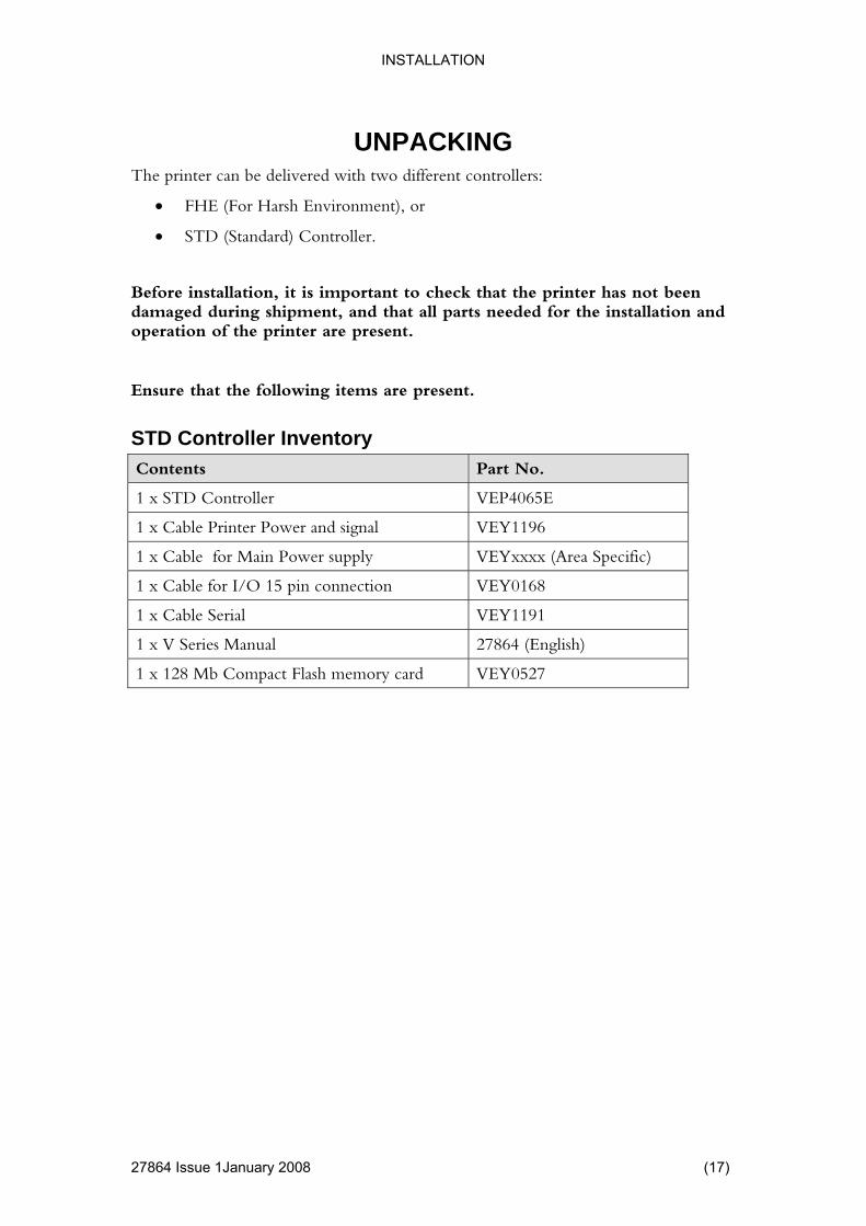
UNPACKING o different controllers:
nment), or
• STD (Standard) Controller.
nt to check that the printer has not been damaged during shipment, and that all parts needed for the installation and operation of the printer are present.
tems are present.
er Inventory
The printer can be delivered with tw
• FHE (For Harsh Enviro
Before installation, it is importa
Ensure that the following i
STD ControllContents Part No.
1 x STD Controller VEP4065E
1 x Cable Printer Power and signal Y1196 VE
1 x Cable for Main Power supply Area Specific) VEYxxxx (
1 x Cable for I/O 15 pin connection VEY0168
1 x Cable Serial VEY1191
1 x V Series Manual 27864 (English)
1 x 128 Mb Compact Flash memory card VEY0527
27864 Issue 1January 2008 (17)
INSTALLATION
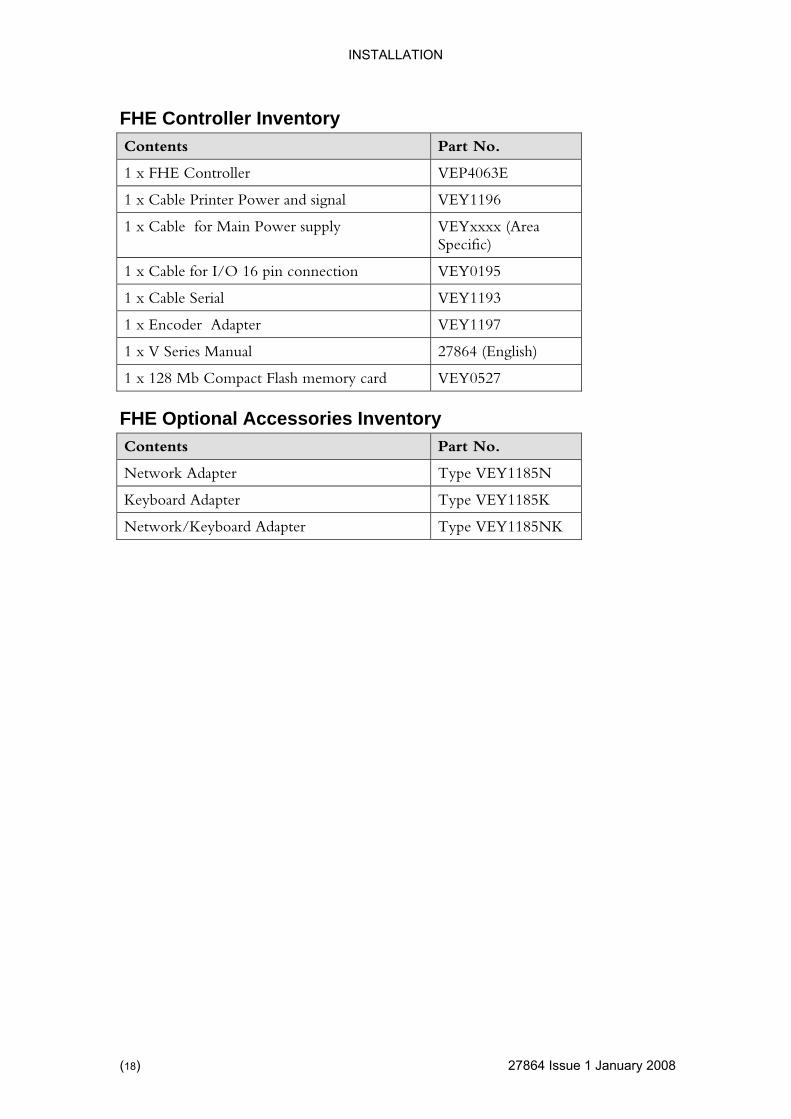
FHE Controller Inventory Contents Part No.
1 x FHE Controller VEP4063E
1 x Cable Printer Power and signal 96 VEY11
1 x Cable for Main Power supply Area cific)
VEYxxxx (Spe
1 x Cable for I/O 16 pin connection Y0195 VE
1 x Cable Serial VEY1193
1 x Encoder Adapter VEY1197
1 x V Series Manual 27864 (English)
1 x 128 Mb Compact Flash memory card VEY0527
FHE Optional Accessories Inventory Contents Part No.
Network Adapter Type VEY1185N
Keyboard Adapter Type VEY1185K
Network/Keyboard Adapter Type VEY1185NK
(18) 27864 Issue 1 January 2008
INSTALLATION
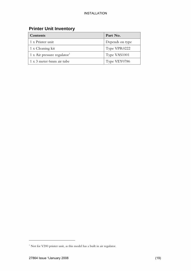
Printer Unit Inventory Contents Part No.
1 x Printer unit s on type Depend
1 x Cleaning kit Type VPR0222
1 x Air pressure regulator1 AS1001 Type V
1 x 3 meter 6mm air tube Type VEY0786
1 Not for V200 printer unit, as this model has a built in air regulator.
27864 Issue 1January 2008 (19)
INSTALLATION
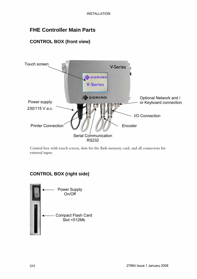
FHE Controller Main Parts
20) 27864 Issue 1 January 2008
CONTROL BOX (front view)
Touch screen
Optional Network and / Keyboard connection
Control box with touch screen, slots for the flash memory card, and all connectors for
CONTROL BOX (right side)
external input.
Printer Connection
Power supply or
I/O Connection
Encoder
Serial Communication RS232
230/115 V a.c.
Power SupplyOn/Off
Compact Flash CardSlot <512Mb
(

INSTALLATION
STD Controller Main Parts
4 Issue 1January 2008 (21)
tion)
Allows the creation of labels, programming and electronically control machine handling and receive all internal service instru
iewed b g, without ha ed.
Control Box with the LCD touch screen display (IP20 Protec
ctions in text and pictures. Label design ving a printer connectcan be prev
efore printin
LAN
Compact
Card Slot Flash
Printer ConnectionLAN
I/O Input (Packaging Machine) Encoder
V100 and V200 model only
Power Supply 230V a.c./115V a.c.
PC Screen VGA Connection Keyboard Connection
Com 2 Serial RS232
cessible) (Not ac
Com 1 Serial RS232 Input
2786
INSTALLATION
22) 27864 Issue 1 January 2008
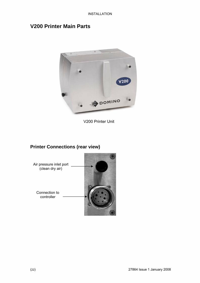
rts V200 Printer Main Pa
tions (rear view) Printer Connec
Connection to controller
Air pressure inlet port y air)
V200 Printer Unit
(clean dr
(
INSTALLATION
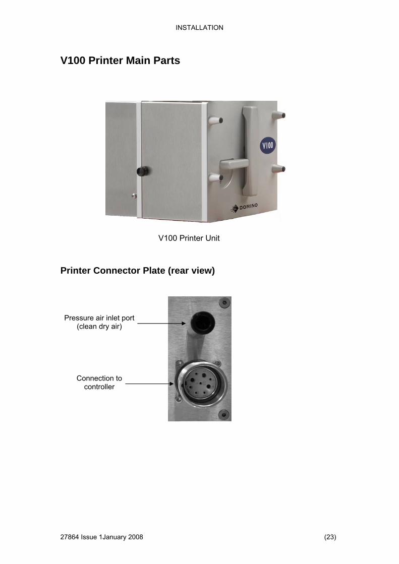
V100 Printer Main Parts
4 Issue 1January 2008 (23)
Printer Connector Plate (rear view)
V100 Printer Unit
Pressure air inlet port (clean dry air)
Connection to controller
2786

INSTALLATION
) 27864 Issue 1 January 2008
The system offers a wide range of printing options.
V400 Printer Unit
V400 Printer main parts
V400 Printer front view with cover removed
Ribbon Web
Platen
(24
INSTALLATION
4 Issue 1January 2008 (25)
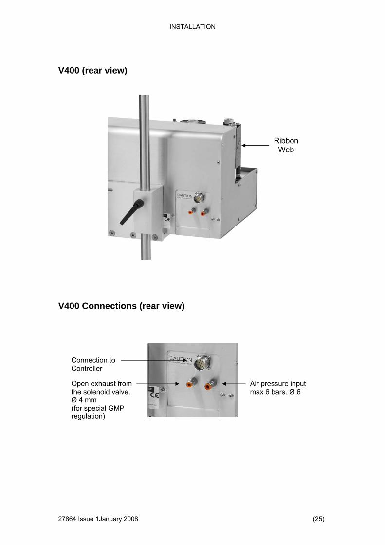
V400 (rear view)
Ribbon Web
V400 Connections (rear view)
Connection toControll
er
Open exhaust from the solenoid valve. Ø 4 mm (for special GMP regulation)
Air pressure input max 6 bars. Ø 6
2786
INSTALLATION
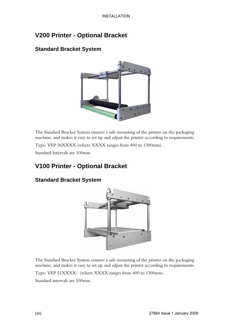
V200 Printer - Optional Bracket
Standard Bracket System
The Standard Bracket System ensures a safemachine, and makes it eas
mounting of the printer on the packaging y to set up and adjust the printer according to requirements.
s from 400 to 1300mm).
Standard Intervals are 100mm
V100 Printer - Optional Bracket
Standard Bracket System
Type: VEP 56XXXX (where XXXX range
The Standard Bracket System ensures a safe mounting of the printer on the packaging machine, and makes it easy to set up and adjust the printer according to requirements.
Type: VEP 51XXXX: (where XXXX ranges from 400 to 1300mm.
Standard intervals are 100mm.
(26) 27864 Issue 1 January 2008
INSTALLATION
4 Issue 1January 2008 (27)
ystem
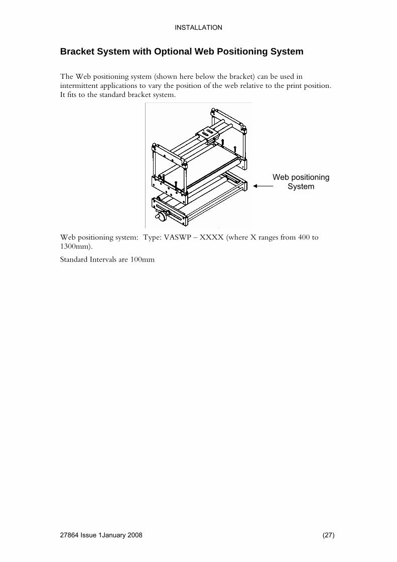
n the position of the web relative to the print position.
It fits to the standard bracket system.
Bracket System with Optional Web Positioning S
The Web positioning system (shown here below the bracket) can be used iintermittent applications to vary
Web positioningSystem
Web positioning system: Type: VASWP – XXXX (where X ranges from 400 to 1300mm).
Standard Intervals are 100mm
2786

INSTALLATION
V400 - Optional Manual Bracket
Manual Bracket System
Bracket parts. 1. Mounting plate for the V400 printer 2. Packaging machine large mounting angle 3. Packaging machine small mounting angle
The Manual Bracket System ensures a safe mounting of the printer on the packaging ma ne, a akes to set up and adjust the printer according to requirements.
Bracket Sy
Type: VASHBTM100X (where X determines the width)
chi nd m
stem for V400:
it easy
X Min. Max. Width Width Width
4 750 mm
610 mm
5 490 mm 630 mm
6 730 mm 870 mm
(28) 27864 Issue 1 January 2008

INSTALLATION
V400 - Optional Automatic Bracket
4 Issue 1January 2008 (29)
Automatic Bracket System
The automatic bracket system allows the V400 printer to print over a larger area ary)
r to drive the vertical movement and is controlled via roller and
ing machine.
The automatic bracket comprises of unguarded moving parts and must be installed to ensure a safe operating environment.
The automatic bracket is supplied with installation guidelines and an operations manual.
during each printing cycle (whilst the material to be printed remains station
The automatic bracket moves the printer vertically in steps after each horizontal strokeof the printer.
The bracket uses a stepper motoa dedicated control module which uses signals from the V Series contpackag
V400 Printer
Automatic Bracket
2786

INSTALLATION
MECHANICAL INSTALLATION
nals are available:
.
lt free contact which closes when printing is required.
(4) Sufficient space for installation and operation.
(5) If using a V200 an encoder to monitor the substrate speed is required.
Installation Requirements Ensure that the following services and control sig
(1) Power - 115/230 Vac (+10%, -15%) 50/60Hz
(2) Compressed Air - 6 Bar (max.), dry, uncontaminated.
(3) A print start signal - this has to be a vo
(30) 27864 Issue 1 January 2008

INSTALLATION
In ts allation (1
If mounting is a V200 ensure the print head is mounted on the top point of the
ket to the correct distance between the
On the V100 printer the distance should be between 1 and 1.5mm • On the V200 the distance should be between 0.2 to 1.0mm.
V100
) Mount the printer in the bracket system.
Note: rubber roller.
(2) Adjust the nuts on the 4 shafts of the bracrubber plate / rubber roller and the print head.
•
1.0
- 1.2
mm
V200
0 - 1 mm
0.2
- 1 m
m
27864 Issue 1January 2008 (31)
INSTALLATION
(4) Connect cables.
ect the air pressure to the printer and adjust to 2.5 Bar (5 inch printer:
nect the encoder.
assette.
Load the test design from the design library
test print on
t received ced
e top rns on the
ied in both ding on the quality of the packaging material; the contrast
tinue with this t until the best result has been found. The mechanical adjustment
of the printer has now been found and further adjustment of the printer is not needed anymore
• Only V200 - Increase the contrast until an acceptable quality has been achieved.
• Connect the main cable from the controller to the main supply
• Connect the printer cable between the printer and the controller
• Conn3.5 Bar)
• If a V200, con
(5) Turn on the controller.
(6) Put ribbon on the cassette. Follow the instruction inside the c
(7)
(8) Carry out a test print as described below.
• V100 only - when printing with the V100 printer push the the touch screen
• V200 only - when printing with an CM or V200 run the web on the packaging machine with 300 mm / s. (note: the start signal must be in continuous mode)
• Only V200 - If the quality of the print is equal to the printwith the printer then reduce the contrast until the quality is redu(approximate 10% reduction)
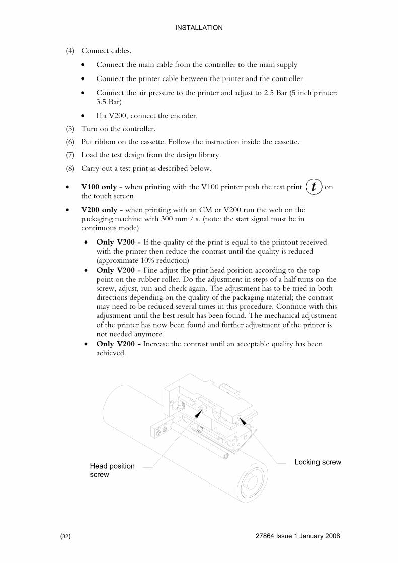
• Only V200 - Fine adjust the print head position according to thpoint on the rubber roller. Do the adjustment in steps of a half tuscrew, adjust, run and check again. The adjustment has to be trdirections depen
ou
may need to be reduced several times in this procedure. Conadjustmen
Locking screw Head position screw
(32) 27864 Issue 1 January 2008

INSTALLATION
4 Issue 1January 2008 (33)
a host e
Electrical FHE controller I/O Connection to machin
24V+
NPN
K1
Vcc
24V+
Vcc
Vcc
Vcc
K2
NPN Start Signal
Ribbon Tension
Input Signals
Signal length min 50ms
Start Signal
Ribbon Tension
Print Ready Signal
Printer Error Signal
Ribbon Warning Signal
Park out Signal
Max voltage: 30V DC
Max current: 100mA
1 Red +
2 Grey 2
5 Black + 5
6 Yellow 6
15 Blue + 15 Ready
16 Green 16 Closed when ready
13 White / Yellow + 13 Error
14 Yellow / Brown 14 Closed when no error
11 Pink + 11 Ribbon Warning
12 Violet 12 Open when low ribbon
9 Park (V400 only)
9 White / Green Signal is closed when
10 Brown printer is in park osition
10 Auto bracket output
To use this output (10), the automatic bracket must be enabled
K1 and K2 wire length
or
or
Use Cable VEY0195
Input
Output
+
_
_
_
+
_
+
_
+
_
Output Signals
p
2786

INSTALLATION
STD controller I/O Connection to a host machine
34) 27864 Issue 1 January 2008
24V+
NPN
K1
Vcc
24V+
Vcc
Vcc
Vcc
K2
NPN Start Signal
Ribbon Tension
Input Signals
Signal length min 50ms
Start Signal
Ribbon Tension
Print Ready Signal
Printer Error Signal
Ribbon Warning Signal
Park out Signal
Max voltage: 30V DC
Max current: 100mA
5 Yellow +
13 Black / White 13
7 Blue + 7
15 Red White 15
4 Orange + 4 Ready
12 Light Green 12 Closed when ready
3 Red + 3 Error
11 Pink 11 Closed when no error
2 Brown + 2 Ribbon Warning
10 White 10 Open when low ribbon
1 Park (V400 only)
1 Black Signal is closed when
9 Grey printer is in park posit
9 Auto bracket output
To use this output (9) the automatic bracket must be enabled
K1 and K2 wire length
or
or
Use Cable VEY0168
Input
Output
+
_
_
_
+
_
+
_
+
_
Output Signals
(
INSTALLATION
4 Issue 1January 2008 (35)
ARE
ne the settings you wish to save in the design. The menu
files.
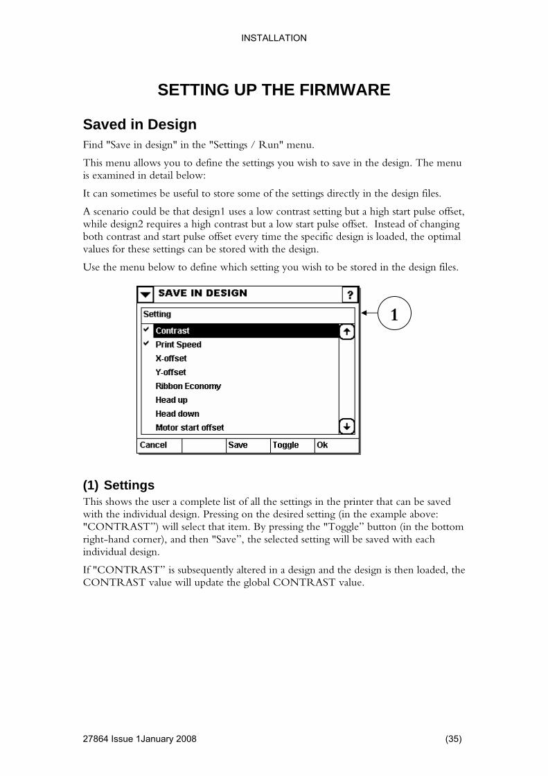
pulse offset, start pulse offset. Instead of changing
he optimal values for these settings can be stored with the design.
Use the menu below to define which setting you wish to be stored in the design files.
e saved g (in the example above:
"CONTRAST”) will select that item. By pressing the "Toggle” button (in the bottom right-hand corner), and then "Save”, the selected setting will be saved with each individual design.
If "CONTRAST” is subsequently altered in a design and the design is then loaded, the CONTRAST value will update the global CONTRAST value.
SETTING UP THE FIRMW
Saved in Design Find "Save in design" in the "Settings / Run" menu.
This menu allows you to defiis examined in detail below:
It can sometimes be useful to store some of the settings directly in the design
A scenario could be that design1 uses a low contrast setting but a high start while design2 requires a high contrast but a lowboth contrast and start pulse offset every time the specific design is loaded, t
1
(1) Settings This shows the user a complete list of all the settings in the printer that can bwith the individual design. Pressing on the desired settin
2786

INSTALLATION
36) 27864 Issue 1 January 2008
he use of a print counter. That means it can be used to print a defined amount of prints.
ter ob is
ting will continue until manually ended (or the print is otherwise interrupted).
) Action when done
ads the print job when the last print is printed.
s the print job (a new number of desired prints must be
• b, when the last
(3) Protect print memory If enabled, a print in the print memory cannot be overwritten by an external source. To load another print job, the current job must be (manually) unloaded first.
Print Counter The system supports t
1 2
3
(1) Enable prompting of print counIf this check box is selected, the system will prompt the operator (when a jmanually started) for the number of prints to do. The prin
Please note that this setting only applies to a print job started on the printer itself. If adesign is transferred, the sender determines the "number of prints”.
(2Use this field to define what should happen when the required number of prints has been printed.
The options are:
• Quit print: Unlo
• Restart print: Restartselected)
Ask: The operator is asked whether to restart or unload the joprint has been printed.
(
INSTALLATION
4 Issue 1January 2008 (37)
et up some of the
clude; date, u.
d users are recommended to go through this menu before starting the printer for the first time.
ime/Date the time and date in the printer’s system. The time set in this by the printer when calculating the various types of RTC. See
(2) Error/Warning to define when the printer should send a ”Warning” or an
is getting
riables rint its ID
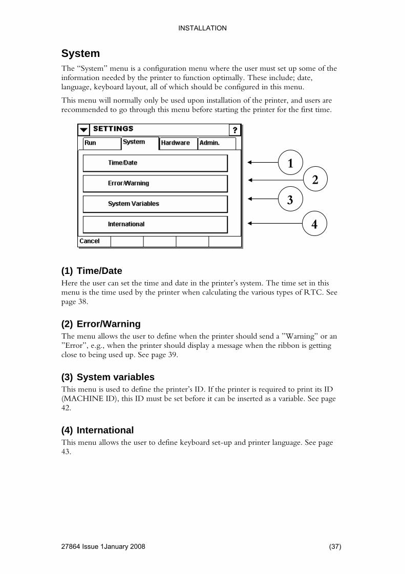
ACHINE ID), this ID must be set before it can be inserted as a variable. See page 42.
(4) International This menu allows the user to define keyboard set-up and printer language. See page 43.
SystemThe “System” menu is a configuration menu where the user must sinformation needed by the printer to function optimally. These inlanguage, keyboard layout, all of which should be configured in this men
This menu will normally only be used upon installation of the printer, an
1 2
3
4
(1) THere the user can setmenu is the time usedpage 38.
The menu allows the user”Error”, e.g., when the printer should display a message when the ribbonclose to being used up. See page 39.
(3) System vaThis menu is used to define the printer’s ID. If the printer is required to p(M
2786

INSTALLATION
Time / Date
38) 27864 Issue 1 January 2008
The time and date in the printer can be set here.
(1) Set Time Pressing “Set Time” will allow the user to key in the
(2) Set Date Set the date in the printer system here. Pressing “Set Date” will allow the user to alter the date.
1
2
Define the printer’s time here.local time.
(

INSTALLATION
4 Issue 1January 2008 (39)
warning or error e case of
g” the user will be informed on the screen but the printer will carry on
f “Error” the printer will display an error message on screen and stop
To switch from “Error” to “Warning” simply press the button.
he arrow keys The “Error/Warning” menu contains two screens that the user can scroll between. By
d arrow key the user will come to the next screen display. By s screen
lay.
o independent ways of detecting the fault.
ivates the ribbon alarm sensor
otated (measured by the ribbon warning sensor) even
g When the ribbon roll is almost empty the ribbon-warning feature is activated (the ribbon warning output is activated).
By setting this feature to “Error” the printer will stop when the diameter of the ribbon roll is equal to the value set in the "Activate ribbon warning when diameter is below:" field.
Error / Warning This menu allows users to determine when the printer should send amessage. The difference between “Warning” and “Error” is that in th“Warninoperating.
In the case ooperating.
1
(1) T
pressing the right-hanpressing the left-hand arrow key, the user will be returned to the previoudisp
(2) Ribbon Alarm When the ribbon is broken, the system has tw
• A dancer arm act
• The ribbon roll has not rthough a certain amount of ribbon was used.
(3) Ribbon Warnin
2
3
4
2786
INSTALLATION
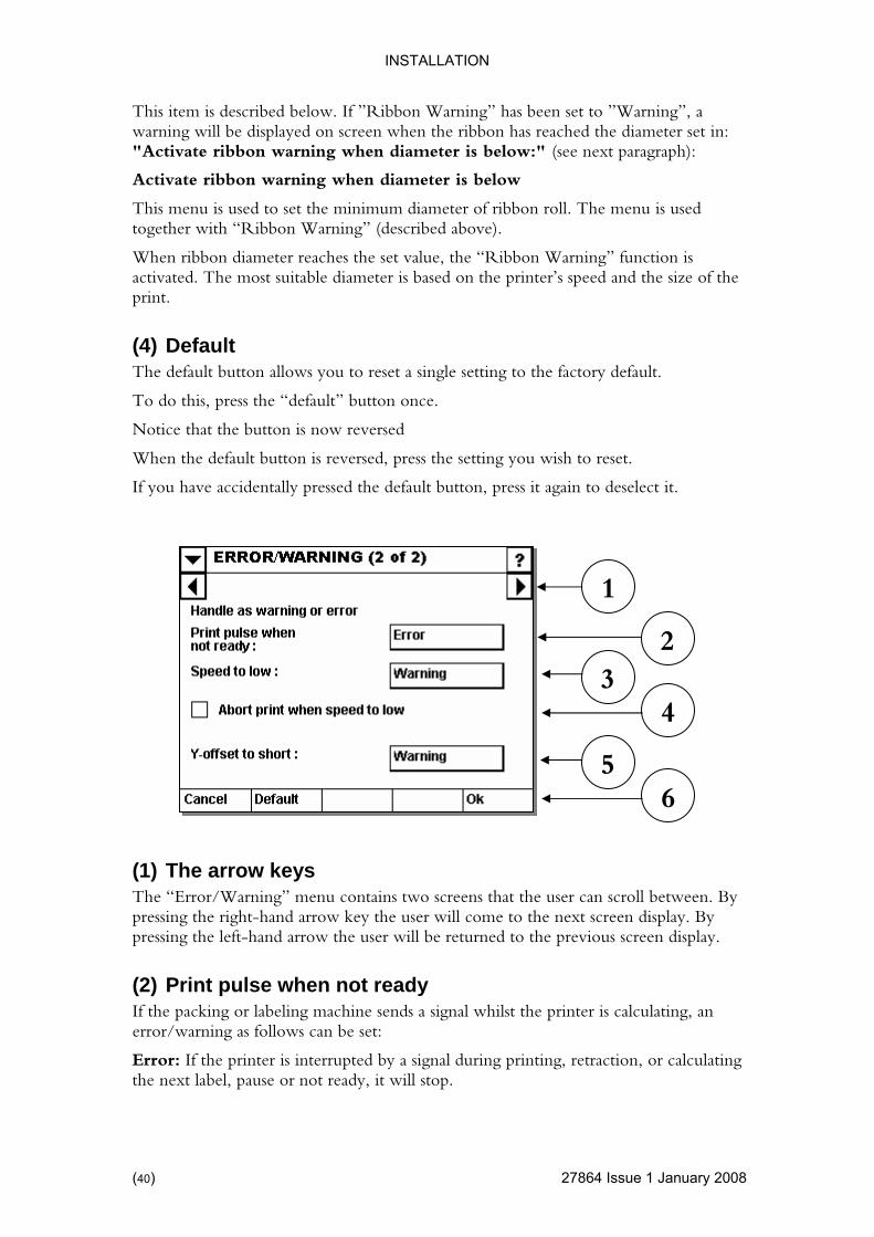
This item is described below. If ”Ribbon Warning” has been set to ”Warnwarning will be displayed on screen when the ribbon has reached the d
ing”, a iameter set in:
s below:" (see next paragraph):
r of ribbon roll. The menu is used
activated. The most suitable diameter is based on the printer’s speed and the size of the
eset a single setting to the factory default.
When the default button is reversed, press the setting you wish to reset.
If you have accidentally pressed the default button, press it again to deselect it.
l between. By ey the user will come to the next screen display. By
display.
(2) Print pulse when not ready If the packing or labeling machine sends a signal whilst the printer is calculating, an error/warning as follows can be set:
Error: If the printer is interrupted by a signal during printing, retraction, or calculating the next label, pause or not ready, it will stop.
"Activate ribbon warning when diameter i
Activate ribbon warning when diameter is below
This menu is used to set the minimum diametetogether with “Ribbon Warning” (described above).
When ribbon diameter reaches the set value, the “Ribbon Warning” function is
print.
(4) Default The default button allows you to r
To do this, press the “default” button once.
Notice that the button is now reversed
1
(1) The arrow keys The “Error/Warning” menu contains two screens that the user can scrolpressing the right-hand arrow kpressing the left-hand arrow the user will be returned to the previous screen
2 3
6 5
4
(40) 27864 Issue 1 January 2008

INSTALLATION
Note: if the printer is interrupted by a signal during printing, retraction or calculatinglabel, pause, not ready, it will ignore the signal. The system will first accept theit has finished calculating. Thus producti
the next next signal when
on will not halt if the printer’s maximum speed is exceeded (but some products may miss a print).
ed too low
If the web speed is below 50 mm/s, a warning or error signal will be displayed on the
if the speed is too low. If he printer remains in its current print position and when the emains of the current print is finished.
ing or error al will be displayed on the screen. If the Y-offset is too short the print head cannot
t pixels and hence the print may not comply with the desired quality e minimum Y-offset depends on the print speed and the actual design to
Notice that the button is now reversed. When the default button is reversed, press the setting you wish to reset.
If the default button was accidentally pressed, press it again to deselect it.
(3) Spe(CM-Types)
screen, in accordance to the settings.
(4) Abort print when speed too low (CM-Types)
By selecting the field, the printer will abort the current print the setting is unselected tweb is started again, the r
(5) Y-offset too short If the distance between the label start and the first line are too short, a warnsignprint the firsstandards. Thprint.
(6) Default The default button allows the user to reset a single setting to the factory default. To do this press the “default” button once.
27864 Issue 1January 2008 (41)

INSTALLATION
System Variables
42) 27864 Issue 1 January 2008
Use this setting to assign a name to the printer. It is this name that the machine id able (page 133) refers to.
ith the host name (see page 55).
mpted hen the design is unloaded again,
e internal system drive is searched for information about any design being printed. If such information is found, the design in question is loaded and any prompted variables will automatically be filled in.
Please note that any counters and real time variables in the design is initialised as it would be during a normal job load.
(1) Machine ID
(identity) vari
Please do not confuse the machine id w
(2) Hotstart The system has limited hot start functionality.
When ever a design is loaded, the name of the design and all entries for provariables are stored on the internal system drive. Wthe information is purged from the internal system drive.
If the system is switched on, th
1 2
(
INSTALLATION
International
4 Issue 1January 2008 (43)
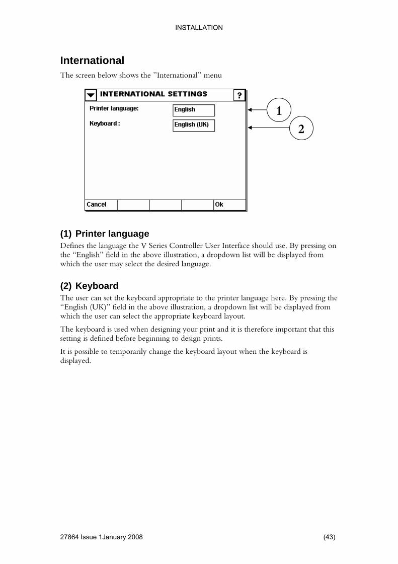
The screen below shows the ”International” menu
Defines the language the V Series Controller User Interface should use. By pressing on eld in the above illustration, a dropdown list will be displayed from
the printer language here. By pressing the ayed from
The keyboard is used when designing your print and it is therefore important that this setting is defined before beginning to design prints.
It is possible to temporarily change the keyboard layout when the keyboard is displayed.
(1) Printer language
the “English” fiwhich the user may select the desired language.
(2) Keyboard The user can set the keyboard appropriate to“English (UK)” field in the above illustration, a dropdown list will be displwhich the user can select the appropriate keyboard layout.
1 2
2786
INSTALLATION
Hardware
44) 27864 Issue 1 January 2008
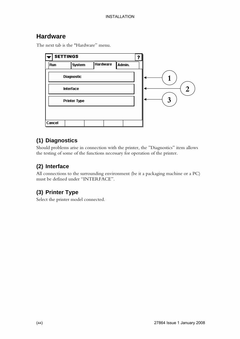
The next tab is the "Hardware” menu.
(1) Diagnostics s arise in connection with the printer, the ”Diagnostics” item allows
the surrounding environment (be it a packaging machine or a PC) FACE”.
(3) Printer Type Select the printer model connected.
Should problemthe testing of some of the functions necessary for operation of the printer.
(2) Interface All connections to must be defined under “INTER
12
3
(

INSTALLATION
Diagnostics
4 Issue 1January 2008 (45)
ckaging machine.
print unit.
/ Voltages / Temperatures
The menu will further display information about the voltage to the print head and stepper motors.
Finally, the menu will show the current temperature of the print head.
(1) I/O test Use this menu to verify the interface to the pa
(2) Sensor test Use this menu to verify the sensors on the
(3) SpeedUse this menu to measure the speed of the web.
3
1
2
2786

INSTALLATION
I/O Test
46) 27864 Issue 1 January 2008
(1) Input lumn shows the status of the four inputs to the system. Possible values are
(2) Output
(3) Loop test The loop test requires the use of a special cable (loop cable) that will test the unit’s input/output signals.
The input coopen or closed.
Use the buttons to force the output to either open or closed (simply press the output you wish to change).
3
1 2
(

INSTALLATION
Sensor Test The menu display reflects the actual printer attached (the screen below is for a V200 printer)
vated if the dancer arm reached this reflective sensor. To e sensor, place something reflective in front of the sensor and
The ribbon-warning sensor monitors the rotation of the roll with unused ribbon. Use r to block the fork sensor and verify that the sensor is activated.
r. On these models, simply turn the roll of unused ribbon and verify that the sensor is activated.
that the sensor is activated.
oder and verify that the screen changes. The screen changes for each
Start Winder (V200 printer only)
Printer has a reflective sensor that monitors the second dancer arm’s position. Place something reflective in front of the sensor and verify the sensor is activated.
Ribbon Alarm The ribbon alarm is actimanually activate thverify that the sensor is activated.
Ribbon Warning
a piece of pape
On some models, the ribbon warning is a reflective senso
Printer Open Open and close the cassette and verify
Encoder Activate the encpulse from the encoder (12 pulses per mm).
The speed test can be used to verify the function of the encoder.
27864 Issue 1January 2008 (47)

INSTALLATION
Stop Winder
’s position. Place something reflective in front of the sensor and verify the sensor is activated.
(V200 Printer only)
Printer has a reflective sensor that monitors the second dancer arm
(48) 27864 Issue 1 January 2008

INSTALLATION
4 Issue 1January 2008 (49)
the surrounding environment (be it a packaging machine or a PC) must be defined here.
(1) Serial Communication munication menu to define the behavior of the serial port of the
vice.
tings terface with the packaging machine.
ork sed to set-up IP address.
e printer.
(See page 53)
(4) Screen Calibrate Make a manual update with a pointing device for the touch screen settings.
Interface All connections to
1
Use the serial comsystem. The serial port can be used to connect a PC, scale or other de
(2) I/O SetUse the I/O settings menu to set up the in
(3) NetwEthernet LAN Set-up, u
Ethernet can be used to transfer designs and to remotely control th
2 3
4
2786

INSTALLATION
Serial Communication
50) 27864 Issue 1 January 2008
Use this menu to modify the baud rate, number of data and stop bits and also to k.
nu is disabled.
(3) Require user logon If this setting is enabled, no serial data is accepted before the sender has been authorised (user name and password of a user known to the system).
(1) Com1 Settings
modify the parity chec
Note: Hardware handshake is always enabled on this system.
(2) Com2 Settings The Com2 port of the system is reserved for future use and this me
1 2
3
(
INSTALLATION
I/O Settings
4 Issue 1January 2008 (51)
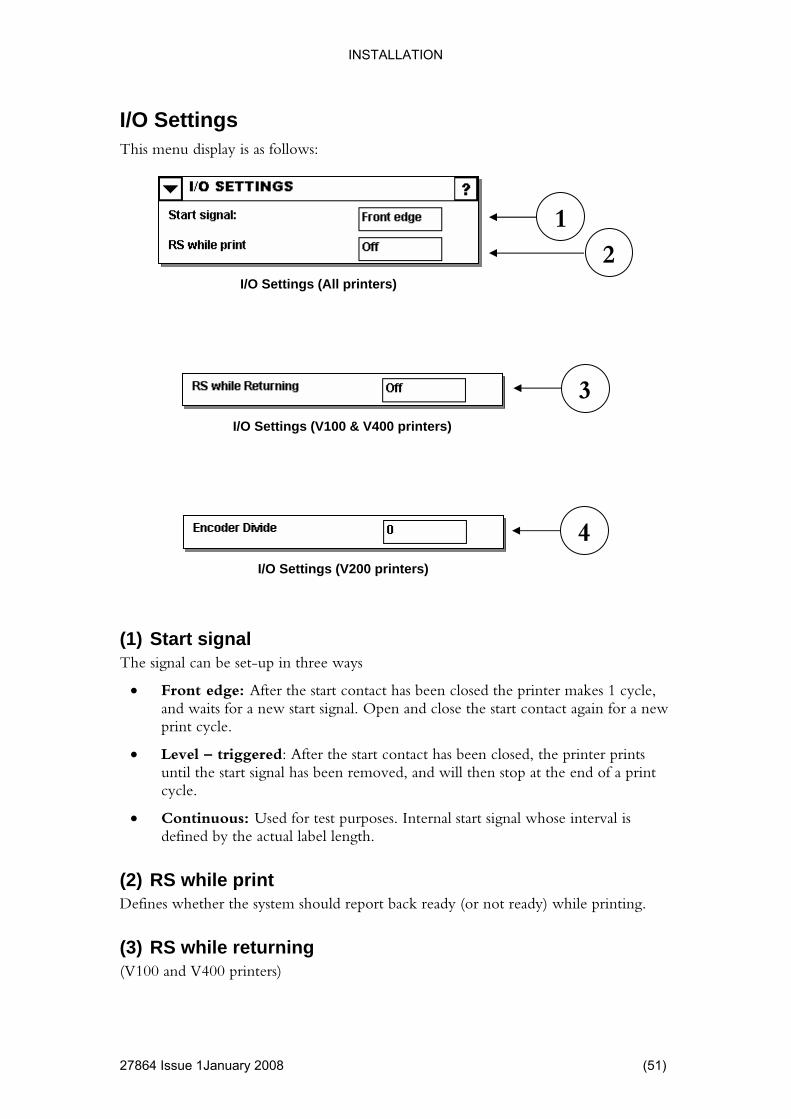
This menu display is as follows:
es 1 cycle, waits for a new start signal. Open and close the start contact again for a new
Level – triggered: After the start contact has been closed, the printer prints ignal has been removed, and will then stop at the end of a print
• Continuous: Used for test purposes. Internal start signal whose interval is label length.
(2) RS while print Defines whether the system should report back ready (or not ready) while printing.
(3) RS while returning (V100 and V400 printers)
1 2
I/O Settings (All printers)
(1) Start signal The signal can be set-up in three ways
• Front edge: After the start contact has been closed the printer makand print cycle.
•until the start scycle.
defined by the actual
I/O Settings (V200 printers)
4
3 I/O Settings (V100 & V400 printers)
2786

INSTALLATION
Defines whether the system should report ready (or not ready) while the print head is returning to its home position.
er Divide
ue pulses per mm. E.g. t gives 48 pulses per mm.
(The value zero and one requires the same encoder).
(4) Encod(V200 printers)
If set to zero, the encoder must give 12 pulses per mm.
If set to another value, the encoder must give 12 times that valsetting the value to 4 requires and encoder tha
(52) 27864 Issue 1 January 2008

INSTALLATION
Network
4 Issue 1January 2008 (53)
The settings related to network is also divided into several screens.
(1) Network Adapter A list of available network adapters is shown. Press one of the available adapters to set it up.
1
2786
INSTALLATION
Network IP Address
54) 27864 Issue 1 January 2008
ocal network administrator for guidelines on how to set up and use a local area network.
rs
ter Name
m a server, or
s active. If
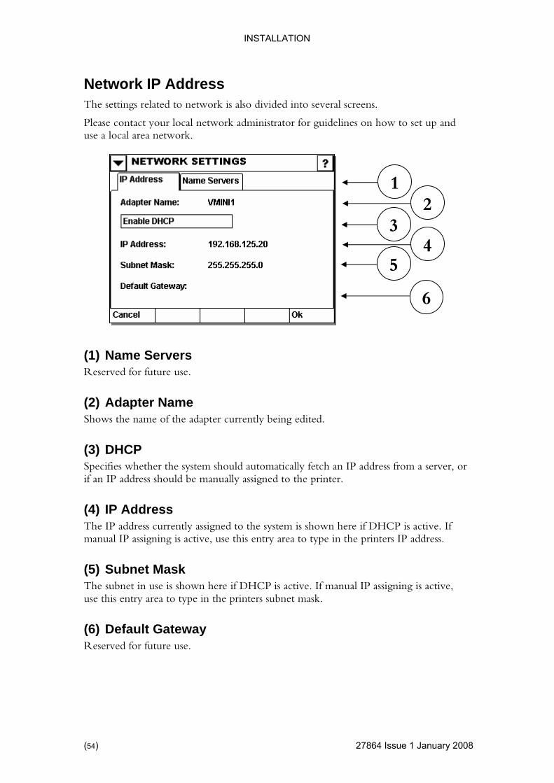
manual IP assigning is active, use this entry area to type in the printers IP address.
k The subnet in use is shown here if DHCP is active. If manual IP assigning is active, use this entry area to type in the printers subnet mask.
(6) Default Gateway Reserved for future use.
The settings related to network is also divided into several screens.
Please contact your l
1 2
3 4
5
6
(1) Name ServeReserved for future use.
(2) AdapShows the name of the adapter currently being edited.
(3) DHCP Specifies whether the system should automatically fetch an IP address froif an IP address should be manually assigned to the printer.
(4) IP AddressThe IP address currently assigned to the system is shown here if DHCP i
(5) Subnet Mas
(

INSTALLATION
Network Host Name
4 Issue 1January 2008 (55)
This is the printer’s networking name. The printer can be found on the local area e hostname.
inters cannot have the same name.
(3) Require user logon If this setting is enabled, no serial data is accepted before the sender has been authorised (user name and password of a user known to the system).
1 2
3
(1) Hostname
network using th
Note: Two pr
(2) Listen Port Set this to 700.
2786
INSTALLATION
Network ODBC Service
56) 27864 Issue 1 January 2008
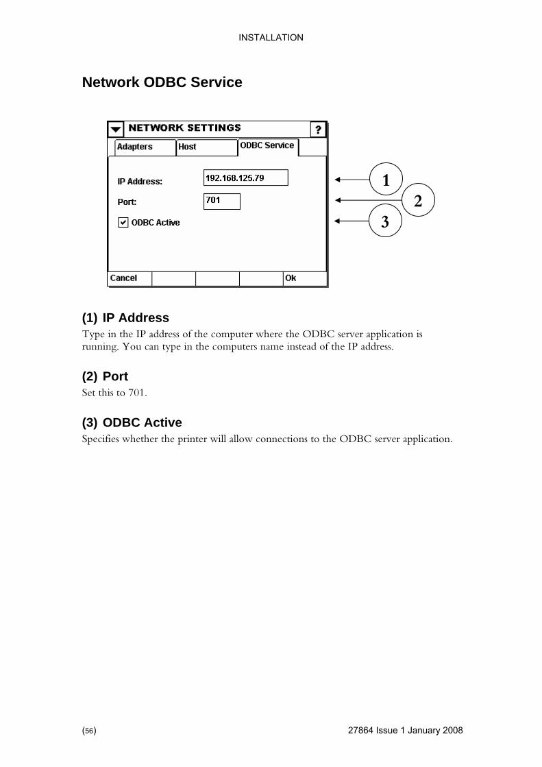
(1) IP Address the IP address of the computer where the ODBC server application is
u can type in the computers name instead of the IP address.
(3) ODBC Active Specifies whether the printer will allow connections to the ODBC server application.
1 2
3
Type in running. Yo
(2) Port Set this to 701.
(
INSTALLATION
Printer Type
4 Issue 1January 2008 (57)
h time the print head is changed, the user must remember to key in the resistance of the print head. Print head
digits and is indicated on the bottom of the print head.
ing an incorrect value may decrease the lifetime of the print head.
rom the start point
the printer, please take time to measure the correct distance the a value. If the setting is too high, the carrier will
er.
, mark the field.
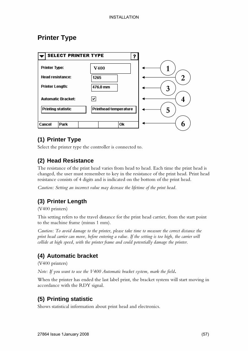
When the printer has ended the last label print, the bracket system will start moving in accordance with the RDY signal.
(5) Printing statistic Shows statistical information about print head and electronics.
(1) Printer Type Select the printer type the controller is connected to.
(2) Head Resistance The resistance of the print head varies from head to head. Eac
resistance consists of 4
Caution: Sett
(3) Printer Length (V400 printers)
This setting refers to the travel distance for the print head carrier, fto the machine frame (minus 1 mm).
avoid damage toCaution: To print head carrier can move, before enteringcollide at high speed, with the printer frame and could potentially damage the print
(4) Automatic bracket (V400 printers)
Note: If you want to use the V400 Automatic bracket system
1 V400
2
6
5
3 4
2786

INSTALLATION
Print head temperature Use this menu to set a warm up temperature for the print head (requires a heating
ess than 10 degrees Celsius)
If no heater is installed (or you do not wish to use it) set the requested temperature to
(V400 printers)
Moves the print head carrier to/from park position.
element in the print head).
The current temperature can be monitored here as well.
For applications where the ambient temperature is cold (lthe print quality can sometimes improve if the heater is activated.
zero.
(6) Park
(58) 27864 Issue 1 January 2008
INSTALLATION
4 Issue 1January 2008 (59)
his menu allows a variety of user profiles to be set up as well as other administrative options.
ly for use by the person responsible for the running of the different printer users to be set up in the system, and these
This menu allows the user to access a list of all the printer’s internal and external files. rename, move, etc. all of these files.
nd to migrate data from the controller.
de grading or changing the V200 software.
xt boot” rinter to
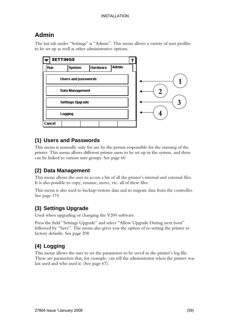
(4) Logging This menu allows the user to set the parameters to be saved in the printer’s log file. These are parameters that, for example, can tell the administrator when the printer was last used and who used it. (See page 67).
Admin The last tab under “Settings” is “Admin”. T
(1) Users and Passwords This menu is normally onprinter. This menu allows can be linked to various user groups. See page 60
(2) Data Management
It is also possible to copy,
This menu is also used to backup/restore data aSee page 174
(3) Settings UpgraUsed when up
Press the field “Settings Upgrade” and select “Allow Upgrade During nefollowed by “Save”. The menu also gives you the option of re-setting the pfactory defaults. See page 208
1 2
3
4
2786
INSTALLATION
Users and Passwords
60) 27864 Issue 1 January 2008
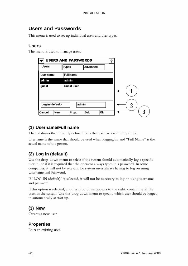
This menu is used to set up individual users and user types.
The menu is used to manage users.
ll name The list shows the currently defined users that have access to the printer.
ult) a specific
f it is required that the operator always types in a password. In some n using
If “LOG IN (default)” is selected, it will not be necessary to log on using username ord.
lected, another drop down appears to the right, containing all the users in the system. Use this drop down menu to specify which user should be logged
ally at start up.
(3) New Creates a new user.
Properties Edits an existing user.
Users
(1) Username/Fu
Username is the name that should be used when logging in, and “Full Name” is the actual name of the person.
(2) Log in (defaUse the drop-down menu to select if the system should automatically loguser in, or icompanies, it will not be relevant for system users always having to log oUsername and Password.
and passw
If this option is se
in automatic
2
1
3
(
INSTALLATION
Delete Deletes the selected user.
4 Issue 1January 2008 (61)
ors forget their password the unit must be returned for repair.
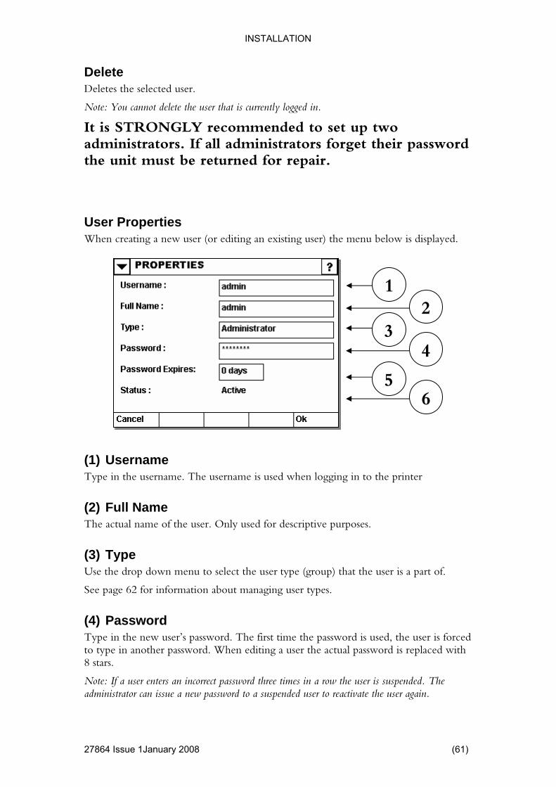
User Properties When creating a new user (or editing an existing user) the menu below is displayed.
Type in the username. The username is used when logging in to the printer
iptive purposes.
rt of.
age 62 for information about managing user types.
Type in the new user’s password. The first time the password is used, the user is forced to type in another password. When editing a user the actual password is replaced with 8 stars.
Note: If a user enters an incorrect password three times in a row the user is suspended. The administrator can issue a new password to a suspended user to reactivate the user again.
Note: You cannot delete the user that is currently logged in.
It is STRONGLY recommended to set up two administrators. If all administrat
(1) Username
(2) Full Name The actual name of the user. Only used for descr
(3) Type Use the drop down menu to select the user type (group) that the user is a pa
See p
(4) Password
5
1
6
2 3
4
2786

INSTALLATION
(5) Password Expir
) 27864 Issue 1 January 2008
a certain number of days, you can define it here. If
If a user’s password expires they are forced to change the password before a real login is accepted.
The status of the user (new user, Active user or suspended).
User Types The menu used to manage user types.
column (User Type) shows the name of the user type.
s an optional description of the user type.
mn indicates how many users is a part of the group.
s a new user type.
Properties Edits an existing user type.
The user type “Administrator” and “Guest” is read-only and cannot be modified or deleted.
es If the password should expire afterset to zero, the password never expires.
Note:
(6) Status
(1) User Type List The list shows the currently available user types.
The first
The second column i
The last colu
(2) New Create
1
2
(62

INSTALLATION
Delete
4 Issue 1January 2008 (63)
u wish to y all the users that are a part of that group to be a part of
another group (or delete the users if desired).
When creating a new user type (or editing an existing user type) the menu below is shown.
ommended that this is used.
wed to user can have access to. Insert a check mark on
at the user type should have access to.
(4) Save Saves the changes.
Toggle Inserts (or removes) a checkmark on the security item that is selected.
Deletes the selected user type.
Note: You cannot delete a user type that still has users assigned to that group. If yodelete a user type you must first modif
User Type (Properties)
1
(1) Name Type in the name of the user type.
(2) Description Type in an optional description. It is rec
(3) AlloThis is a list of all security items that a those th
4
2
3
2786
INSTALLATION
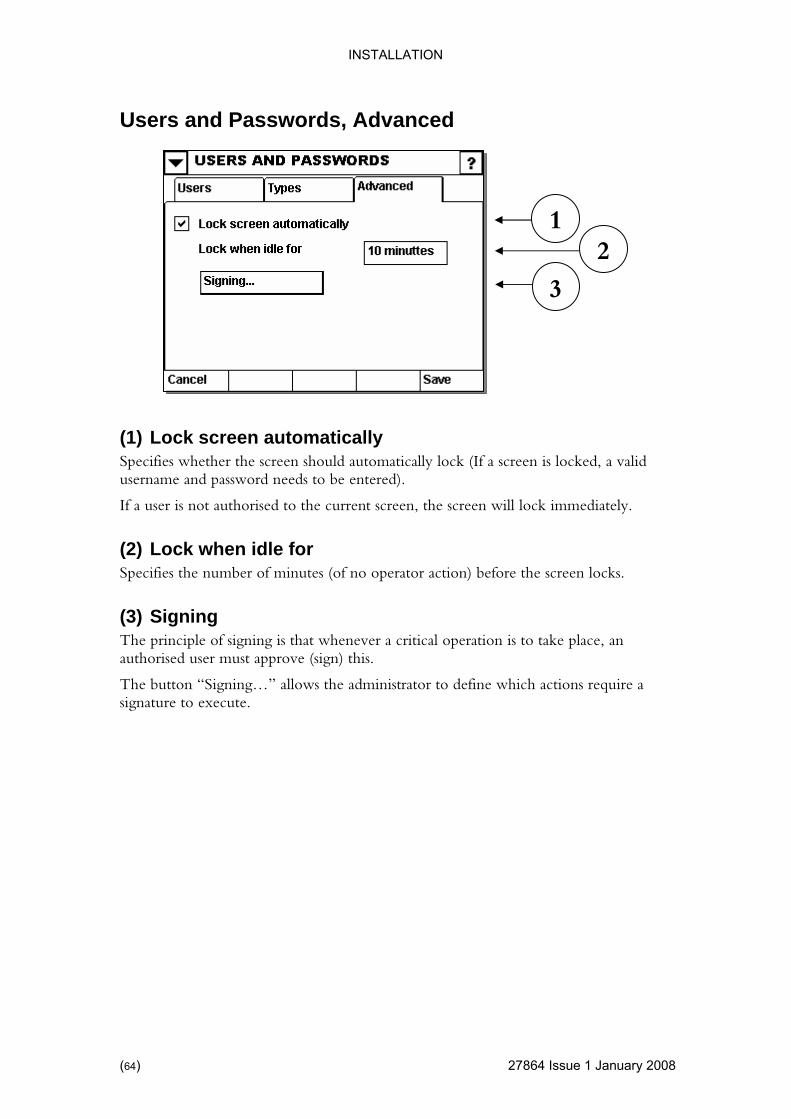
Users and Passwords, Advanced
64) 27864 Issue 1 January 2008
Specifies whether the screen should automatically lock (If a screen is locked, a valid eds to be entered).
mediately.
hen idle for een locks.
The principle of signing is that whenever a critical operation is to take place, an authorised user must approve (sign) this.
The button “Signing…” allows the administrator to define which actions require a signature to execute.
1 2
3
(1) Lock screen automatically
username and password ne
If a user is not authorised to the current screen, the screen will lock im
(2) Lock wSpecifies the number of minutes (of no operator action) before the scr
(3) Signing
(
INSTALLATION
Signing Setup
4 Issue 1January 2008 (65)
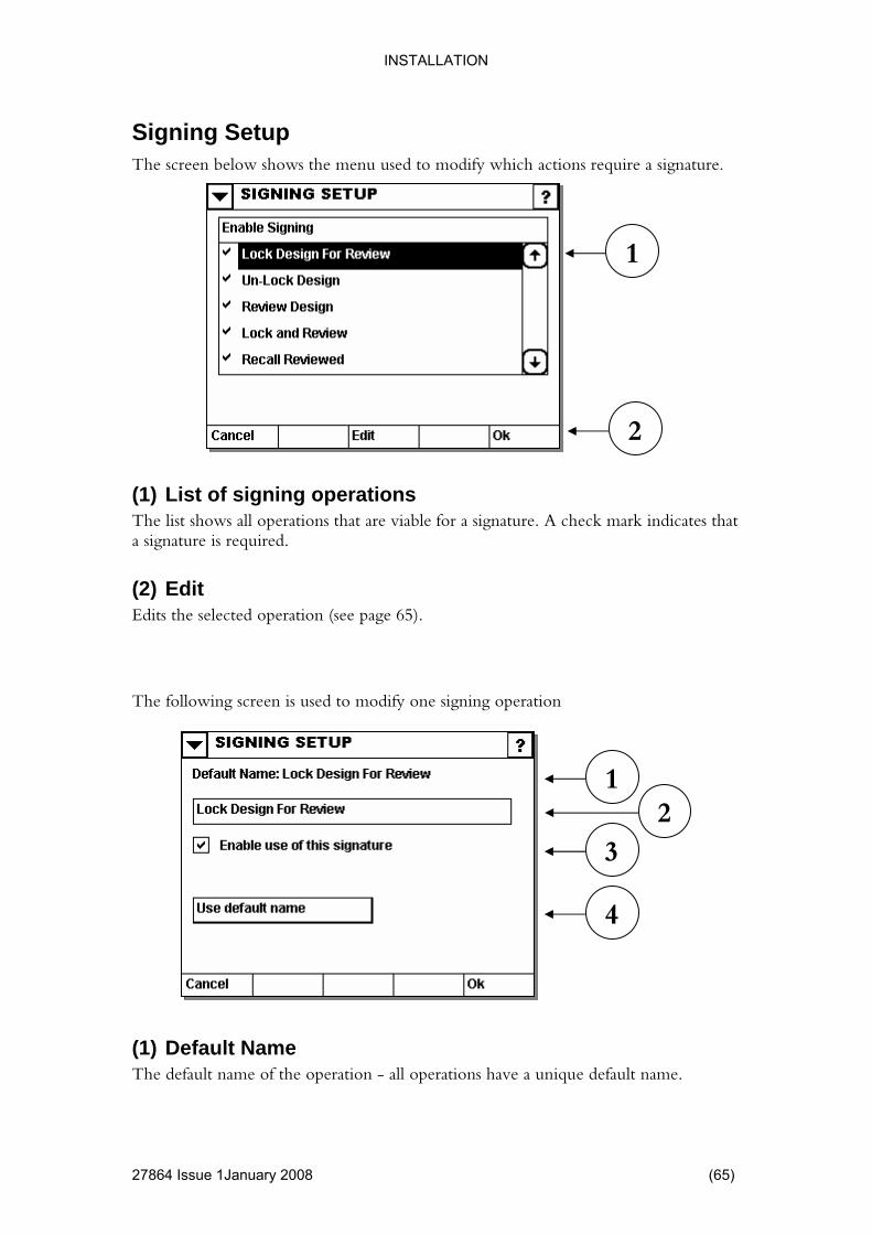
The screen below shows the menu used to modify which actions require a signature.
(1) List of signing operations hows all operations that are viable for a signature. A check mark indicates that
(2) Edit
The following screen is used to modify one signing operation
(1) Default Name The default name of the operation - all operations have a unique default name.
The list sa signature is required.
Edits the selected operation (see page 65).
3 2
4
1
1
2
2786
INSTALLATION
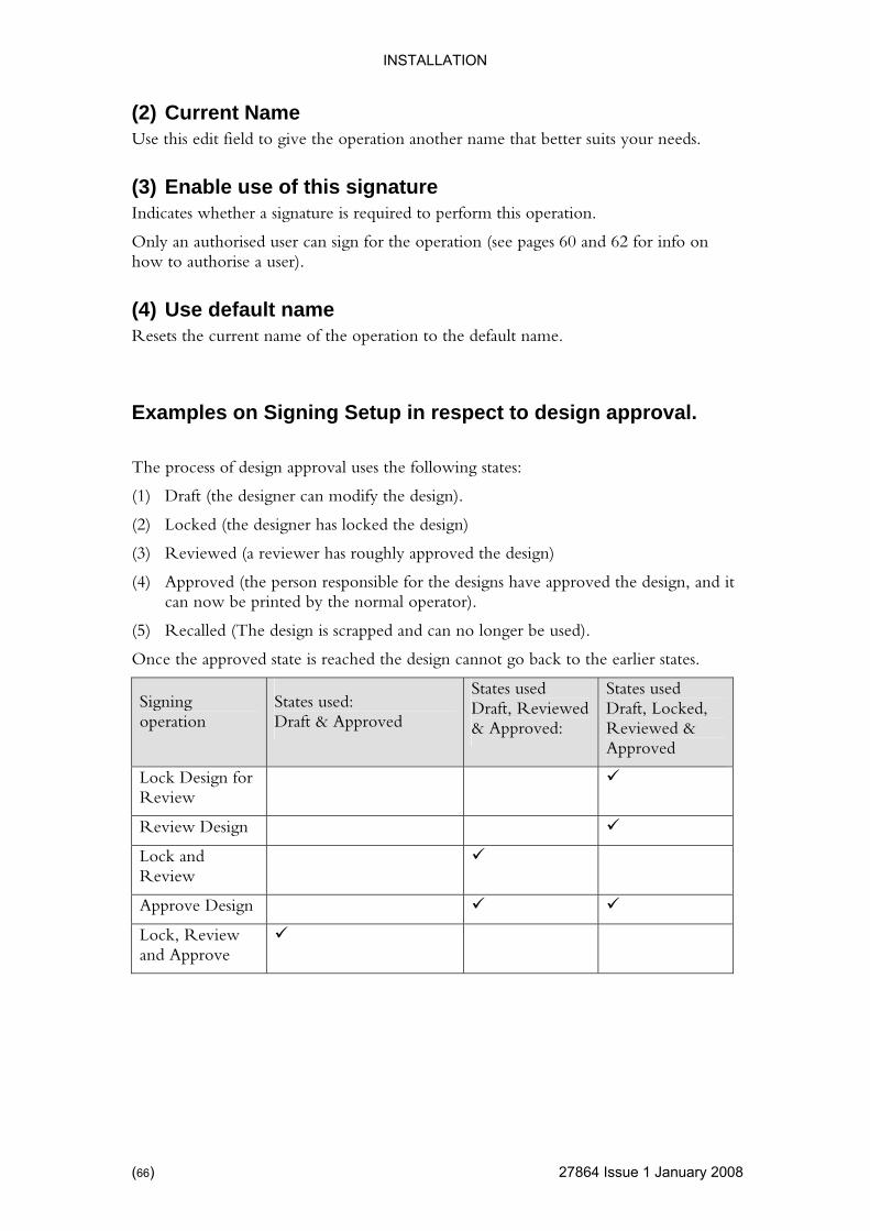
(2) Current Name Use this edit field to give the operation another name that better suits your needs.
60 and 62 for info on
(4) Use default name Resets the current name of the operation to the default name.
ect to design approval.
llowing states:
gn)
e design, and it can now be printed by the normal o
alled (T ped an b
Once the approved state is reached the design cannot go back to the earlier states.
(3) Enable use of this signature Indicates whether a signature is required to perform this operation.
Only an authorised user can sign for the operation (see pages how to authorise a user).
Examples on Signing Setup in resp
The process of design approval uses the fo
(1) Draft (the designer can modify the design).
(2) Locked (the designer has locked the design)
(3) Reviewed (a reviewer has roughly approved the desi
(4) Approved (the person responsible for the designs have approved thperator).
d can no longer (5) Rec he design is scrap e used).
Signing operation
States used States used States used: Draft, Reviewed Draft, Locked, Draft & Approved & Approved: Reviewed &
Approved
Lock Design for Review
Review Desig n
Lock and Review
Approve Design
Lock, Review and Approve
(66) 27864 Issue 1 January 2008

INSTALLATION
Logging
4 Issue 1January 2008 (67)
log: Used by the system (for CFR21 Part 11, the system log cannot be
• User log: Used for user related data.
Basically anything that happens is logged (i.e. an error is acknowledged, a design is being approved, a print job is started, user prompted information, modifying users etc.)
on a network share (using the path specified below)
stored on the internal memory card on a fixed
(2) Directory to store log file if LAN is selected)
ation where the file is to be saved. This can either be done riting the name of directory where
the file is to be saved.
(3) Browse (Only visible if LAN is selected)
Allows a search for the desired location to store the log file.
The system has two logs.
• Systemdisabled)
System Log
1 2
3
(1) LAN Use the drop down to select the media to store the log file.
• LAN: The log file will be stored
• Internal: The log file will belocation
• Disabled: No log file will be generated.
(Only visible
The user may select the locby browsing the printer’s file system or simply by w
2786

INSTALLATION
User Lo
68) 27864 Issue 1 January 2008
ther to ems to log and
e of writing, the user selectable items are all related to printed information in a design.
The log file will be stored on a network share (using the path specified
e stored on the internal memory card on a fixed
(Only visible if LAN is selected)
ation where the file is to be saved. This can either be done simply by writing the name of directory where
(Only visible if LAN is selected)
Allows a search for the desired location to store the log file.
(4) Optional Events Use the menu to select which of the optional events you wish to be logged.
g The user log is an optional log (meaning that the user is free to decide wheactivate this log or not). Also the user has a choice of selecting which itwhich to ignore. At the tim
1
(1) LAN Use the drop down to select the media to store the log file.
• LAN:below)
• Internal: The log file will blocation
• Disabled: No log file will be generated.
(2) Directory to store log file
The user may select the locby browsing the printer’s file system or the file is to be saved.
(3) Browse
2 3
4
(

INSTALLATION
4 Issue 1January 2008 (69)
some optional events. Use this menu to define which of the optional events should be used.
nal Events to Log
Use the toggle button to set/remove a checkmark on the selected event.
In the example above, six different events are selected.
Please note that the log itself must also be activated for any log file to be generated.
User Optional Log Events The User log has the option of logging
1
2
(1) OptioThe list shows the events that the user can choose to log.
(2) Toggle
2786

THIS PAGE INTENTIONALLY LEFT BLANK
(70) 27864 Issue 1 January 2008
ION
CONTENTS
Page
........... 73
...........73
...........73
........... 75
........... 76
...........76
...........77
78
...........79
........... 80
...........80
...........82
........... 83
........... 84
...........84
85
...........86
........... 88
...........88
...........89
...........90
...........92
Fields......................................................................................................93
Inserting Fields .......................................................................................93
Editing Label Field..................................................................................94
Line ........................................................................................................95
PART 3 : OPERAT
SOFTWARE ..................................................................................User Interface..............................................................................Components on the screen .........................................................
FIRMWARE VERSION..................................................................TOUCH SCREEN KEYBOARD .....................................................
Using the Keyboard.....................................................................Single Line Edit ...........................................................................Multi Line Edit.........................................................................................Symbol Keyboard ........................................................................
USING THE EXPLORER...............................................................Basic Principle.............................................................................File Options .................................................................................
MAIN MENU ..................................................................................PRINTING .....................................................................................
Locating the design .....................................................................View Design ...........................................................................................Print Screen.................................................................................
DESIGNING ..................................................................................Getting Started ............................................................................Edit Existing Design ....................................................................The Design Screen......................................................................Design Attributes .........................................................................
27864 Issue 1January 2008 (71)

Box .........................................................................................................96
...........98
.........104
.........107
.........112
.........112
.........113
.........114
118
.........129
.........131
.........133
.........134
.........135
.........138
..........144
145
.........149
......... 150
.........151
Run Settings Economy.........................................................................154
Run Settings Position ...........................................................................158
Run Settings Technical ........................................................................161
Barcode.......................................................................................Graphic........................................................................................Text .............................................................................................Variables .....................................................................................Inserting variables .......................................................................Edit a Variable .............................................................................Sequential Variable .....................................................................Real Time Clo ) ........................................................................ck (RTCShift Code ...................................................................................Prompted Variable.......................................................................Machine ID ..................................................................................User ID ........................................................................................Serial Variable .............................................................................Macro Variable ............................................................................Macro Output Variable ...............................................................Database Variable................................................................................Database Extract Variable...........................................................
SETTINGS.....................................................................................Run..............................................................................................
(72) 27864 Issue 1 January 2008
OPERATION
4 Issue 1January 2008 (73)
RE
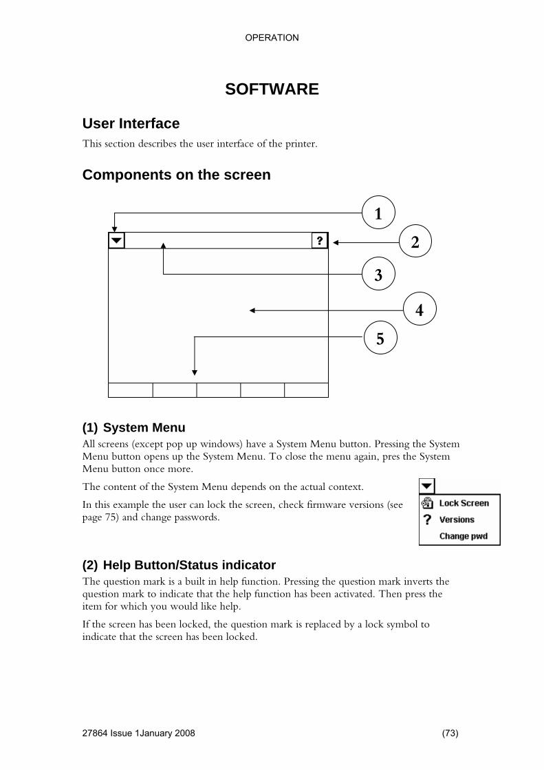
This section describes the user interface of the printer.
Components on the screen
n. Pressing the System System Menu. To close the menu again, pres the System
Menu button once more.
The content of the System Menu depends on the actual context.
reen, check firmware versions (see
dicator The question mark is a built in help function. Pressing the question mark inverts the question mark to indicate that the help function has been activated. Then press the item for which you would like help.
If the screen has been locked, the question mark is replaced by a lock symbol to indicate that the screen has been locked.
SOFTWA
User Interface
1
2
3
4
5
(1) System Menu All screens (except pop up windows) have a System Menu buttoMenu button opens up the
In this example the user can lock the scpage 75) and change passwords.
(2) Help Button/Status in
2786
OPERATION
(3) Title Bar Displays the name of the current screen. Sometimes the title bar contains inabout the current “operation (i.e
formation ., in the file explorer the title will change to “Copy”
when a copy operation is in progress).
ually contains pictures, combo boxes, buttons and text.
ies of buttons that change to reflect the current situation.
nformation or take you to the previous
A Save button will save any unsaved information.
An Ok button will save any unsaved information and revert to the previous screen.
(4) Main area This is where the actual screen information is placed.
The main area us
(5) Menu Row A ser
A Cancel button will discard any unsaved iscreen.
(74) 27864 Issue 1 January 2008
OPERATION
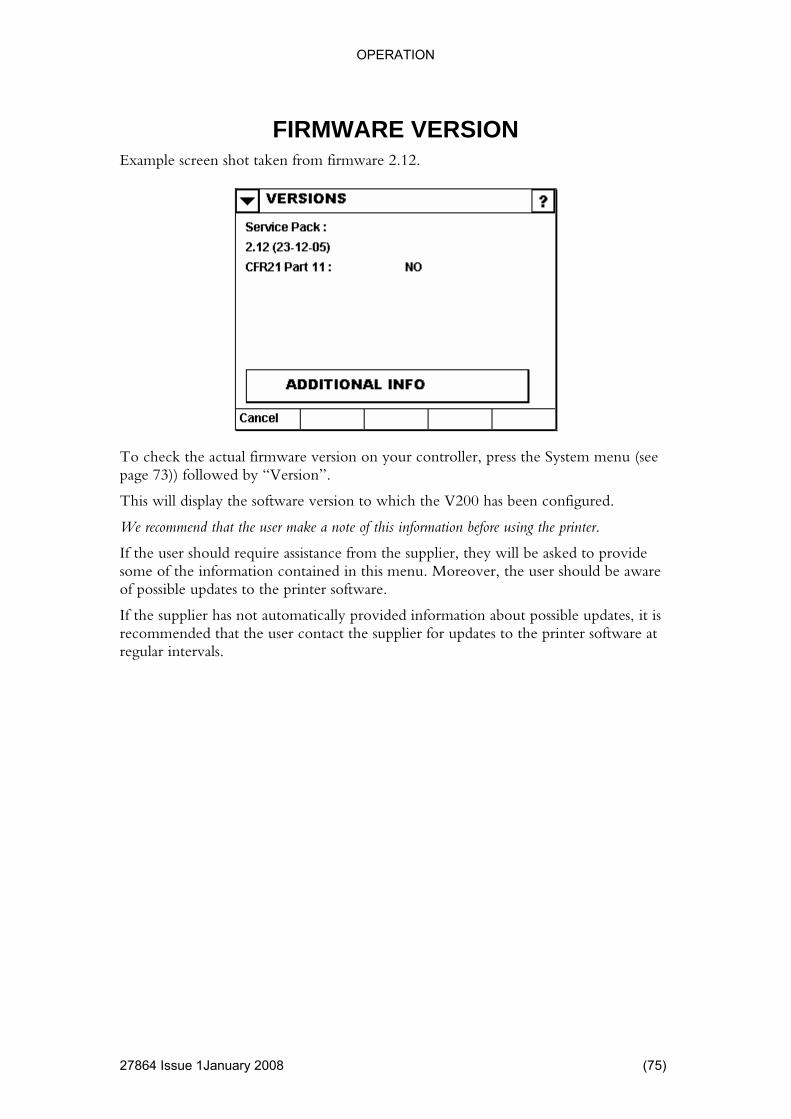
FIRMWARE VERSION Example screen shot taken from firmware 2.12.
ed.
of this information before using the printer.
provide
of possible updates to the printer software.
If the supplier has not automatically provided information about possible updates, it is recommended that the user contact the supplier for updates to the printer software at regular intervals.
To check the actual firmware version on your controller, press the System menu (see page 73)) followed by “Version”.
This will display the software version to which the V200 has been configur
We recommend that the user make a note
If the user should require assistance from the supplier, they will be asked tosome of the information contained in this menu. Moreover, the user should be aware
27864 Issue 1January 2008 (75)

OPERATION
TOUCH SCREEN KEYBO
27864 Issue 1 January 2008
em has a built-in keyboard. The keyboard is activated when a string edit field is pressed.
The menu row of the keyboard can have the following option (depending on the
e keyboard r view of the text.
The default keyboard can be configured according to the nationality of the country involved.
e ke
Clip board Allows user to import text from a text file, cut, copy and paste.
Only available in a multi-line edit field (see page 78)
ARD The syst
Using the Keyboard
context).
Keyboard Use this button to change the keyboard layout temporarily, or to hide thfor bette
To set up th yboard, refer to the following menu:
SETTINGS | System | International (Page 43)
(76)

OPERATION
Single Line Edit
4 Issue 1January 2008 (77)
Used for inputting a single line of text; in this example a filename.
a
board Use this button to change the keyboard layout temporarily, or to hide the keyboard for better view of the text.
See page 76.
(1) Edit areUsed for inputting a single line of text. In this example a filename.
(2) Key
2
1
2786
OPERATION
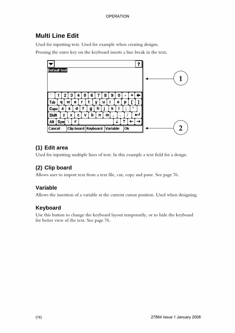
Multi Line Edit
27864 Issue 1 January 2008
gns.
Pressing the enter key on the keyboard inserts a line break in the text.
d for a design.
board .
t the current cursor position. Used when designing.
Keyboard Use this button to change the keyboard layout temporarily, or to hide the keyboard for better view of the text. See page 76.
Used for inputting text. Used for example when creating desi
1
2
(1) Edit areaUsed for inputting multiple lines of text. In this example a text fiel
(2) ClipAllows user to import text from a text file, cut, copy and paste. See page 76
Variable Allows the insertion of a variable a
(78)

OPERATION
Symbol Keyboard Pressing the “Sym” key on the keyboard changes the keyboard to show some
ner. forwards between the various
e keyboard.
Press the “Sym” key again to close the symbolic keyboard.
commonly used symbols.
The user should note the extra keys that appear in the bottom left-hand cor”Prev” and ”Next” can be used to scroll backwards and symbols, as there are more than can be shown on th
27864 Issue 1January 2008 (79)
OPERATION
27864 Issue 1 January 2008
access is required.
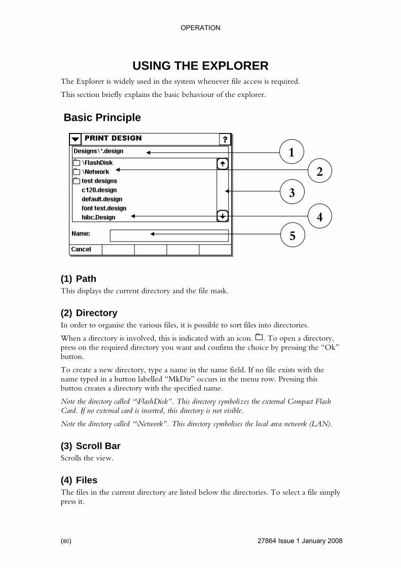
This section briefly explains the basic behaviour of the explorer.
Basic Principle
ories.
USING THE EXPLORERThe Explorer is widely used in the system whenever file
1
2
3
4
5
(1) Path This displays the current directory and the file mask.
(2) Directory In order to organise the various files, it is possible to sort files into direct
When a directory is involved, this is indicated with an icon. . To oppress on the required directory you want an
en a directory, d confirm the choice by pressing the “Ok”
directory with the specified name.
called “\FlashDisk”. This directory symbolizes the external Compact Flash inserted, this directory is not visible.
irectory called “\Network”. This directory symbolises the local area network (LAN).
croll Bar Scrolls the view.
(4) Files The files in the current directory are listed below the directories. To select a file simply press it.
button.
To create a new directory, type a name in the name field. If no file exists with the name typed in a button labelled “MkDir” occurs in the menu row. Pressing this button creates a
Note the directoryCard. If no external card is
Note the d
(3) S
(80)

OPERATION
(5) Name
4 Issue 1January 2008 (81)
Alternatively, a name can be typed in using the keyboard.
this move file.
Certain files (includes design files and text files) can be viewed with an internal viewer.
(3) File Pressing the “File” button shows some options for the selected file.
1 2
3
(1) Ok Pressing the Ok button activates the current function with the selected file. Inexample the function is printing a design. Other functions include copy and
(2) View
2786

OPERATION
File Options
27864 Issue 1 January 2008
If a file is selected in the Explorer, pressing the file button displays the following menu.
the title changes to “COPY”.
The firmware automatically suggests a name for the destination file.
ther directory and/or give the file a new name and press Ok.
copied, the explorer reverts to its previous directory and function.
Just as with Copy.
ive the file a new name
file cannot be restored, and is thus deleted permanently.
(5) Properties Shows size of selected file (or directory) and the available free space as well as the total capacity of the drive on which the file (or directory) is located.
1
(1) Copy Pressing copy returns to the explorer in “Copy” mode. Notice
Go to ano
After the file is
(2) Move
(3) Rename Use the keyboard to g
(4) Delete Deletes the file from the system. Note that the deleted
2 3
4
5
(82)

OPERATION
MAIN MENU
4 Issue 1January 2008 (83)
The main menu is displayed when an authorized user is logged in.
Printing ows access to the printer memory. In other words, if layouts have already
lected and
See page no. 84.
outs.
ptimise the number of ways. Through this menu, the user may correct
and edit the V200’s basic configuration.
on with peripheral equipment such as packing machines or labelling pre when
(4) Security Use this button to log out. This is a common function for multi-user systems. Once logged out, the user must type in a user name and the corresponding password to log in again. Using the “SETTINGS” menu described on page no.60, the administrator can set up different users and their passwords.
1
2
3
4
(1) Start This menu allbeen designed and stored on the accompanying flashcard, these can be seopened here.
The user should not use this menu to edit the stored designs; this is done using the “DESIGN” menu described below.
(2) DesignThis menu allows the user to edit existing layouts, and to create new lay
Read more about this menu on page no. 88.
(3) Settings This menu is mainly used when installing the printer and it is used to oprinter’s performance in a
Communicatiunits is also administered via this menu. Many of the V200’s functions areconfigured by the manufacturer, therefore the user should exercise cautionmaking changes in this menu.
2786

OPERATION
PRINTING
27864 Issue 1 January 2008
Pressing ”START PRINT” in the main menu will call up the following display:
Use the explorer functions to locate the design you wish to print.
n has been made.
has been selected, the "Ok” button can be used. If a design has been chosen and the "Ok” button pressed, the design will be loaded into
The printer is now ready for printing.
(2) View This button allows you to view the selected design, described in detail on page no. 85.
Locating the design
1 2
(1) Ok (Start Printing) The "Ok” button on this display is not active until a selectio
Once either a directory or a file
RAM.
All variables will be initialised and any prompted variables prompted.
(84)

OPERATION
View Design
4 Issue 1January 2008 (85)
The” View” button allows the previewing of the design before printing it.
At each side, there is a small arrow pointing to the edge of the display. The area of the nd these arrows is an active area and covering the arrow with one’s finger
ard
order to
(3) Zoom + / - l which is difficult to read, users can zoom in on individual
allow users to etails in the individual design.
(4) Init Vars / Next Seq Shows the variable contents. By pressing “Next Seq” the program calculates the next set of values (i.e. for counters and real time variables), and shows the result on the screen.
(1) Scroll
display arouwill move the display in the opposite direction of the arrow (just like standWindows scroll action).
(2) Rotate This allows users to rotate their labels so they can be read. Note that this feature does not rotate the actual printout of the design, but only the image on screen infacilitate reading.
If the design contains detaiparts of the design – and out again.
Note: This feature has no influence on the size of the design, but is only there toview d
2
1
3
4
2786
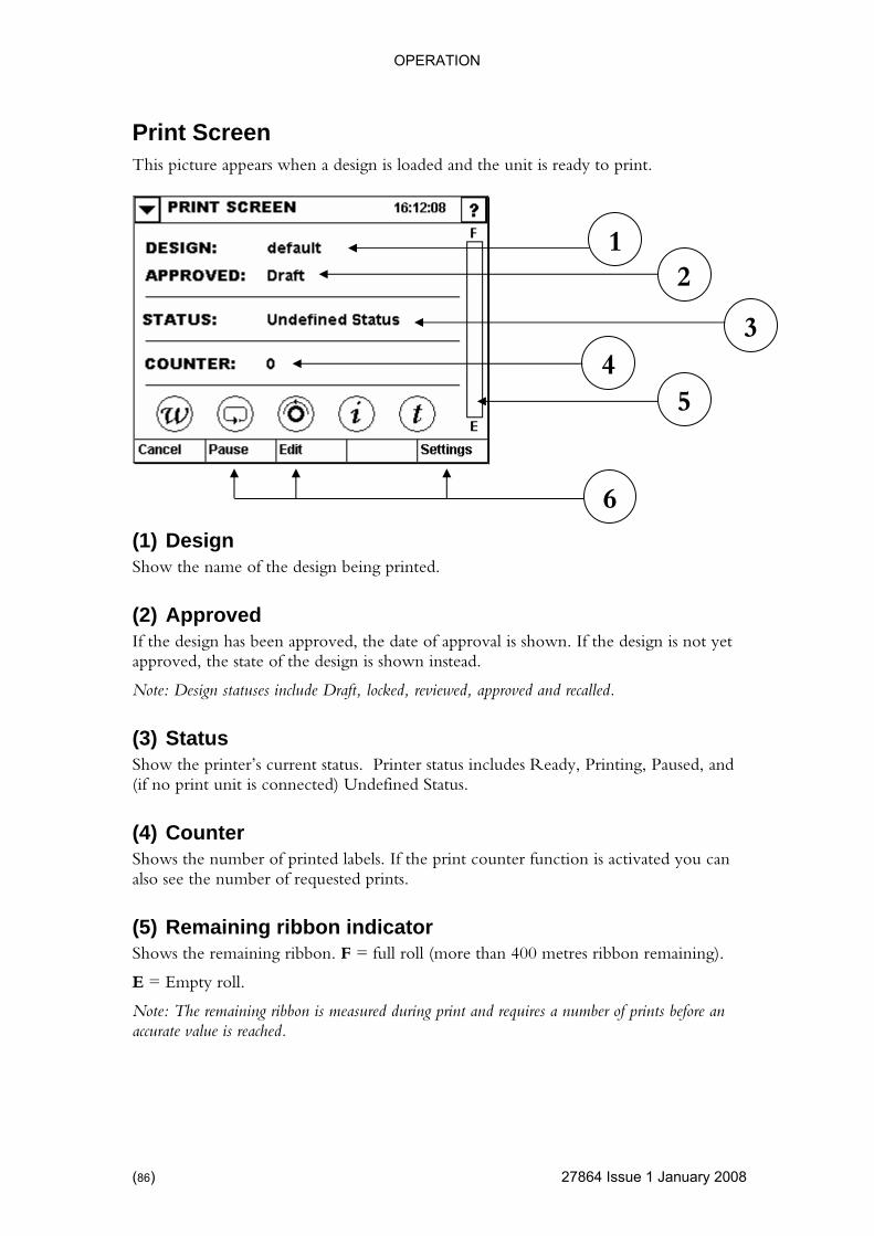
OPERATION
Print Screen
27864 Issue 1 January 2008
This picture appears when a design is loaded and the unit is ready to print.
2 1
n has been approved, the date of approval is shown. If the design is not yet e state of the design is shown instead.
aused, and
efined Status.
umber of requested prints.
(5) Remaining ribbon indicator Shows the remaining ribbon. F = full roll (more than 400 metres ribbon remaining).
E = Empty roll.
Note: The remaining ribbon is measured during print and requires a number of prints before an accurate value is reached.
(1) Design Show the name of the design being printed.
(2) Approved If the desigapproved, th
Note: Design statuses include Draft, locked, reviewed, approved and recalled.
(3) StatusShow the printer’s current status. Printer status includes Ready, Printing, P(if no print unit is connected) Und
(4) Counter Shows the number of printed labels. If the print counter function is activated you can also see the n
3
5 4
6
(86)
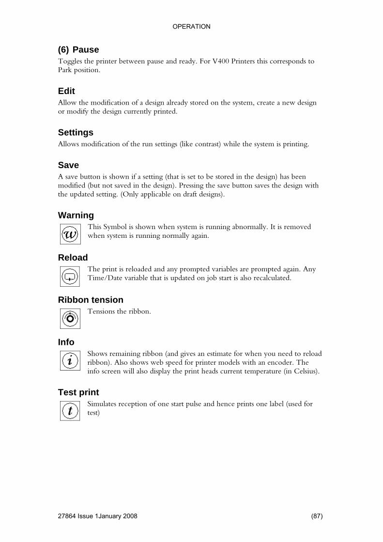
OPERATION
(6) Pause Toggles the printer between pause and ready. For V400 Printers this corresponds to Park position.
already stored on the system, create a new design
s modification of the run settings (like contrast) while the system is printing.
he design) has been ssing the save button saves the design with
ed setting. (Only applicable on draft designs).
Warning
Edit Allow the modification of a designor modify the design currently printed.
Settings Allow
Save A save button is shown if a setting (that is set to be stored in tmodified (but not saved in the design). Prethe updat
when system is running normally again. This Symbol is shown when system is running abnormally. It is removed
Reload
The print is reloaded and any prompted variables are prompted again. Any ble that is updated on job start is also recalculated.
bon tension
Time/Date varia
Rib
Tensions the ribbon.
Info
hows remaining ribbon (and gives an estimate for when you need to reload ribbon). Also shows web speed for printer models with an encoinfo screen will also display the print heads curren
Sder. The
t temperature (in Celsius).
Test print
Simulates reception of one start pulse and hence prints one label (used for test)
27864 Issue 1January 2008 (87)
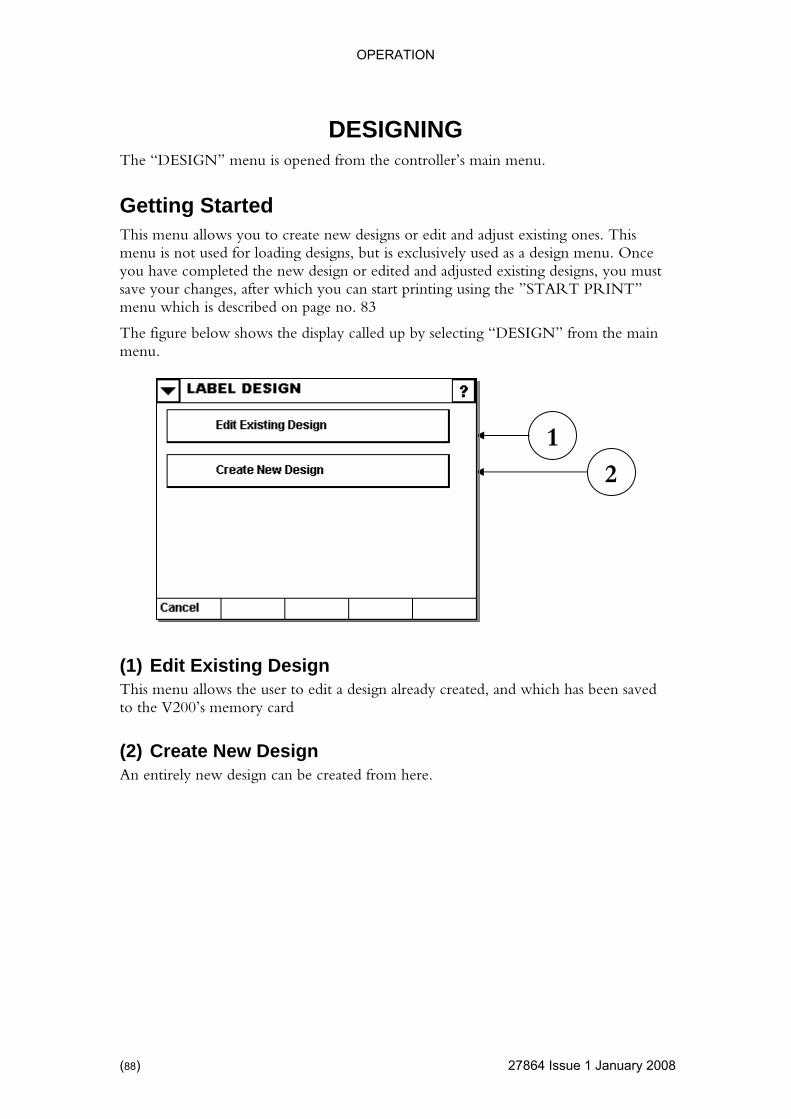
OPERATION
DESIGNING
27864 Issue 1 January 2008
The “DESIGN” menu is opened from the controller’s main menu.
s. This enu. Once
n or edited and adjusted existing designs, you must RINT”
u which is described on page no. 83
The figure below shows the display called up by selecting “DESIGN” from the main menu.
sign already created, and which has been saved
to the V200’s memory card
(2) Create New Design An entirely new design can be created from here.
Getting Started This menu allows you to create new designs or edit and adjust existing onemenu is not used for loading designs, but is exclusively used as a design myou have completed the new desigsave your changes, after which you can start printing using the ”START Pmen
(1) Edit Existing DeThis menu allows the user to edit a design
1
2
(88)
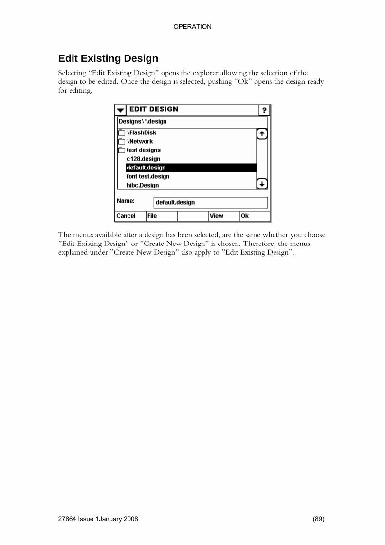
OPERATION
Edit Existing Design Selecting “Edit Existing Design” opens the explorer allowing the selection odesign to
f the be edited. Once the design is selected, pushing “Ok” opens the design ready
for editing.
The menus available after a design has been selected, are the same whether you choose ”Edit Existing Design” or ”Create New Design” is chosen. Therefore, the menus explained under ”Create New Design” also apply to ”Edit Existing Design”.
27864 Issue 1January 2008 (89)

OPERATION
27864 Issue 1 January 2008
ed default). If “Create New Design” has been selected, the name would simply be “Untitled”.
eld or a barcode). If the information within a field needs to be updated a variable is required.
generated by a variable must be linked to a field to be printed. The updated by the system as required.
size and the design status
tes size
Use this menu to approve the design. For maximum security it is recommended that ed designs can be printed by the operator.
(4) New Field Creates a new field. See page: 93.
Edit Field Edit a field contained in the design. See page: 94.
The Design Screen The following screen is displayed after opening an existing design (nam
1
A design can contain fields, variables and settings.
A field is what you directly can see on the print out (i.e., text fi
The informationvariables in a design are automatically
(1) Quick info Displays the design
(2) Design AttribuUse this button to modify the size of the design, and to activate the Cyclefunction. See page: 92.
(3) Design Approval
only approv
2 5 3
6
4 4
(90)
OPERATION
New Variable Create a new variable. See page: 112.
Edit a variable contained in the design. See page: 113.
Allows the designer to make some test prints. (Takes the user to the Print screen, see
(6) Save As les users to save the design using a new name.
Only the
Edit Variable
(5) Test print
page no.86).
This enab
Settings This is a shortcut key to the “SETTINGS” menu described page no. 151. “settings saved in Design” (see page no 35) can be modified here.
e notice that any setting changed here does not affect the global settings until the
View visible when the design is saved on disc. It displays a preview of the design,
Only visible when the design has been modified.
Saves the design using its current name. If the design has not been saved before then it behaves just like the Save As function (6)
Pleasdesign is loaded for printing.
Onlyusing the internal viewer.
Save
27864 Issue 1January 2008 (91)
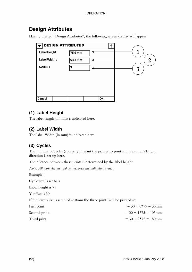
OPERATION
Design Attributes
27864 Issue 1 January 2008
Having pressed ”Design Attributes”, the following screen display will appear:
ht here.
Width
nter to print in the printer’s length n is set up here.
een these prints is determined by the label height.
between the individual cycles.
e is set to 3
t is 75
30
If the start pulse is sampled at 0mm the three prints will be printed at:
First print = 30 + 0*75 = 30mm
Second print = 30 + 1*75 = 105mm
Third print = 30 + 2*75 = 180mm
1 2
3
(1) Label HeigThe label length (in mm) is indicated
(2) LabelThe label Width (in mm) is indicated here.
(3) Cycles The number of cycles (copies) you want the pridirectio
The distance betw
Note: All variables are updated
Example:
Cycle siz
Label heigh
Y-offset is
(92)
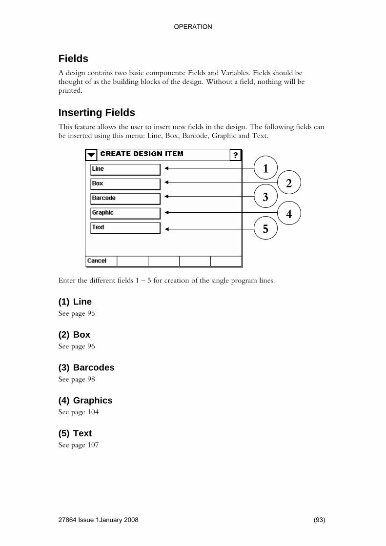
OPERATION
4 Issue 1January 2008 (93)
hould be ht of as the building blocks of the design. Without a field, nothing will be
printed.
This feature allows the user to insert new fields in the design. The following fields can be inserted using this menu: Line, Box, Barcode, Graphic and Text.
different fields 1 – 5 for creation of the single program lines.
e See page 95
See page 96
odes 98
(4) Graphics See page 104
(5) Text See page 107
Fields A design contains two basic components: Fields and Variables. Fields sthoug
Inserting Fields
1
Enter the
(1) Lin
(2) Box
(3) BarcSee page
2 3
4 5
2786
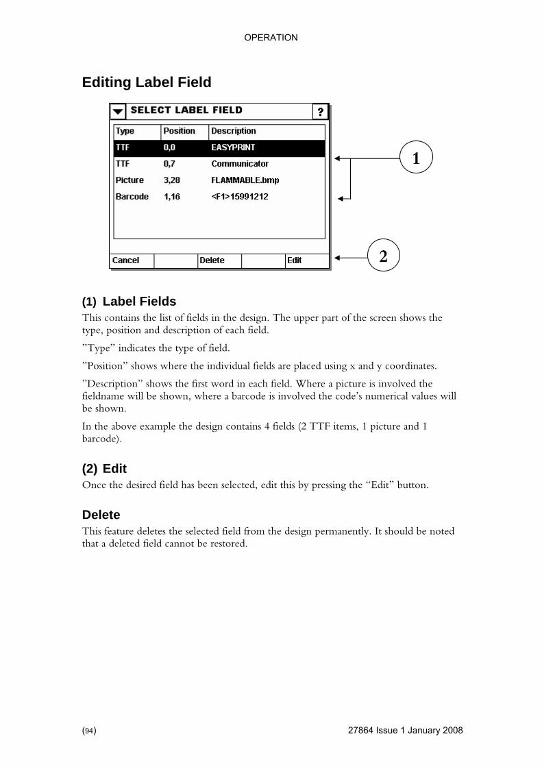
OPERATION
Editing Label Field
27864 Issue 1 January 2008
n” shows where the individual fields are placed using x and y coordinates.
ved the involved the code’s numerical values will
.
ure and 1 barcode).
elected, edit this by pressing the “Edit” button.
Delete This feature deletes the selected field from the design permanently. It should be noted that a deleted field cannot be restored.
(1) Label Fields This contains the list of fields in the design. The upper part of the screen shows the type, position and description of each field.
”Type” indicates the type of field.
”Positio
”Description” shows the first word in each field. Where a picture is involfieldname will be shown, where a barcode isbe shown
In the above example the design contains 4 fields (2 TTF items, 1 pict
(2) Edit Once the desired field has been s
2
1
(94)

OPERATION
4 Issue 1January 2008 (95)
sert a line in the design. The display below shows the user options offered by this feature.
should be considered as a filled box. In the above example, the line will start
(1) X es the x-position (across the print head) of the field.
tion (longitudinally with the print head) of the field.
oved in the writing direction. Numerical
icated.
red.
This allows the width of the line to be indicated.
Numerical values can be entered.
(5) Phantom Allows the item to be hidden during printing, i.e. it will not be printed.
Line Here the user can in
A linefrom (0,0) and end at (10,1)
Defin
Numerical values can be entered.
(2) Y Defines the y-posi
If this value is increased, the field will be mvalues can be entered.
(3) Line Height This allows the height of the line to be ind
Numerical values can be ente
(4) Line width
1
3
2
4
5
2786

OPERATION
27864 Issue 1 January 2008
to the design. The display below shows the options available in this menu.
(1) Height the height of the box to be indicated.
(2) Width of the box to be indicated.
Numerical values can be entered.
ess
rical values can be entered.
Numerical values can be entered.
(5) Phantom Allows the item to be hidden during printing, i.e. it will not be printed.
Box This allows the user to insert a box in
1
This allows
Numerical values can be entered.
This allows the width
(3) Line ThicknThe thickness of the line surrounding the box can be entered here.
Nume
(4) Arc Diameter The corners of the box can to be rounded using this value. Larger values give rounder corners.
2
3 4
5
(96)

OPERATION
1January 2008 (97)
es the x-position (across the print head) of the field.
Defines the y-position (longitudinally with the print head) of the field.
If this value is increased, the field will be moved in the writing direction. Numerical values can be entered.
1 2
(1) X Defin
Numerical values can be entered.
(2) Y
27864 Issue
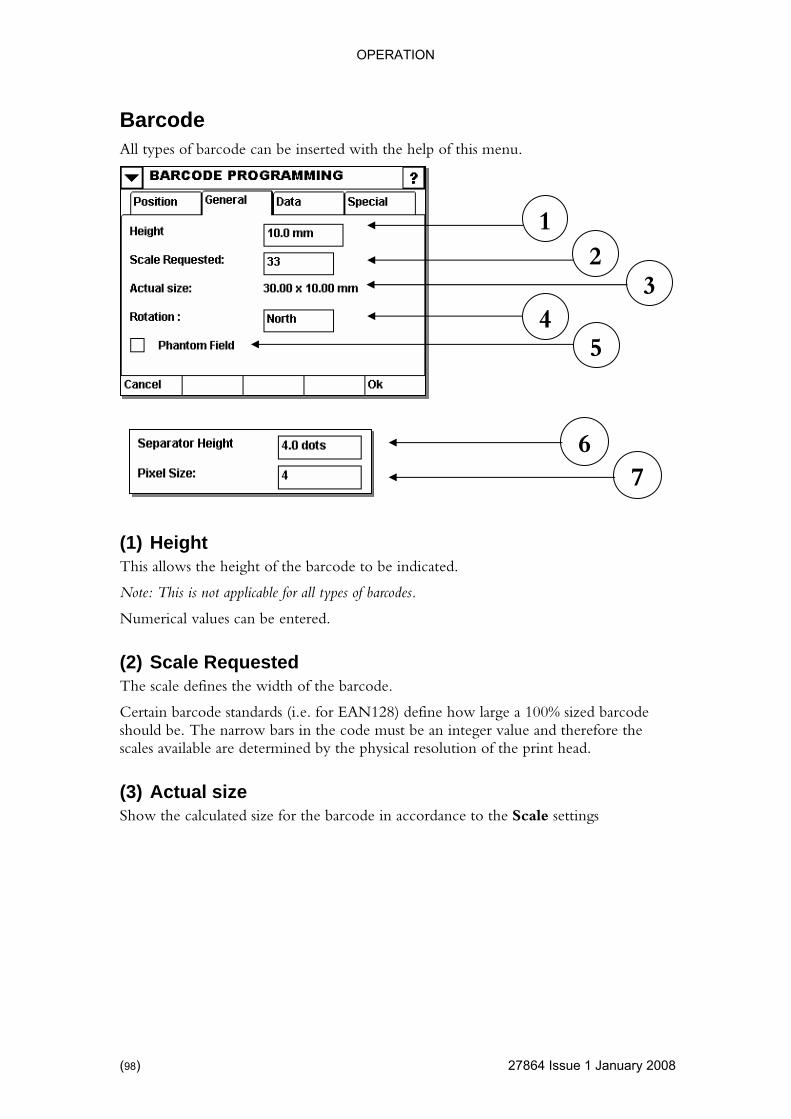
OPERATION
Barcode
27864 Issue 1 January 2008
All types of barcode can be inserted with the help of this menu.
This allows the height of the barcode to be indicated.
for all types of barcodes.
The scale defines the width of the barcode.
nd therefore the scales available are determined by the physical resolution of the print head.
(3) Actual size Show the calculated size for the barcode in accordance to the Scale settings
(1) Height
Note: This is not applicable
Numerical values can be entered.
(2) Scale Requested
Certain barcode standards (i.e. for EAN128) define how large a 100% sized barcode should be. The narrow bars in the code must be an integer value a
7 6
5
1 2
3 4
(98)

OPERATION
4 Issue 1January 2008 (99)
as North, l appear, and
bination with the anchor point
(4) Rotation The field can be rotated to 0, 90,180 and 270 degrees. Directions are statedSouth, East and West. By pressing on a direction, a dropdown menu wilthe user can then select the desired rotation. In com(see page 100) the field can be rotated to suit requirements.
dden during printing, i.e. it will not be Printed.
t mposite component.
Use the Separator height to define the separation thickness between the ordinary barcode and the 2d component.
The separator height must be between pixel size and 2 times pixel size.
(7) Pixel Size GS1 DATABAR and Datamatrix codes do not use the Scale Requested parameter. Instead, the size of the narrow bars (or squares) can be defined with this number.
(5) Phantom Allows the item to be hi
(6) Separator HeighGS1 DATABAR barcodes have the option of having a 2d co
2d Component
Separator
2786
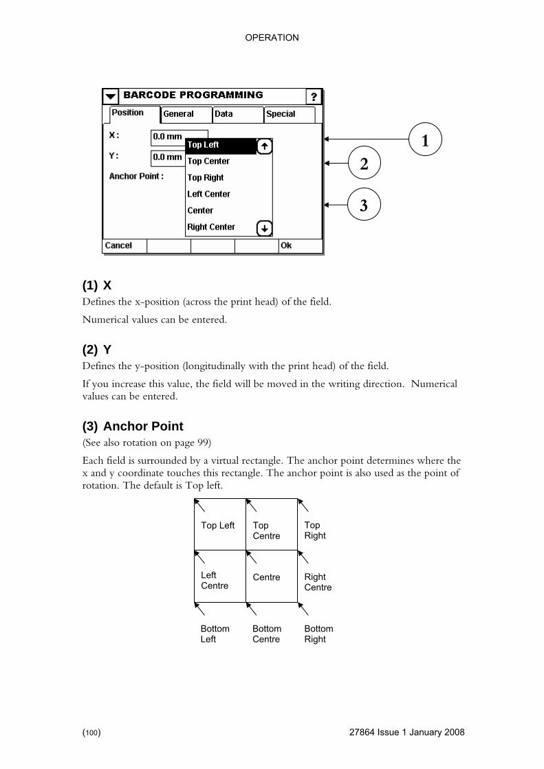
OPERATION
4 Issue 1 January 2008
es the x-position (across the print head) of the field.
Defines the y-position (l
alue, the field will be moved in the writing direction. Numerical
(See also rotation on page 99)
Each field is surrounded by a virtual rectangle. The anchor point determines where the x and y oordinate tou is r le. T chor point is also used as the point of rotation. The default is Top left.
(1) X Defin
Numerical values can be entered.
(2) Y ongitudinally with the print head) of the field.
If you increase this vvalues can be entered.
(3) Anchor Point
c ches th ectang he an
12
3
Bottom Left
Bottom Centre
Bottom Right
Right Centre
p Left To
Left Centre
Centre
Top Right
Top Centre
(100) 2786

OPERATION
ry 2008 (101)
(1) Barcode Type u to select the desired type of barcode. In this example, an
ns is available
If the user wishes to show the values contained in the barcodes, this box should be active. The human readable interpretation will be printed under the actual barcode.
Human readable interpretation for the 2d composite component will be printed above the code (one application identifier per line).
(3) Font type If the “HUMAN READABLE” box is active, the user has the option of choosing the font used to show the barcode’s human readable interpretation.
3
1
2
45
6
7
Use the drop down menEAN128 has been selected. The type of barcode determines which optioon the screen.
(2) Human Readable
27864 Issue 1Janua
OPERATION
(4) Data for Barcode The actual code should be entered here. By pressing this field, a keyboard will appear
tifiers (AI) to variable length AI with the next
(commonly known as pipe) to separate the primary barcode with the 2d e component.
Examples:
where the information can be entered.
Some barcodes (like EAN128 and GS1 DATABAR) use Application Ideninterpret the data. Use the code <F1> to separate aAI. EAN128 furthermore requires a <F1> as the first data.
The standard GS1 DATABAR can only encode the AI number 01 and hence you should only type in the data for this particular AI.
Use the |composit
Type Info Meaning
EAN128 <F1>15240205 5 AI 15 with data 24020
EAN128 15991212 ) with data ta 991212
<F1>10asdf<F1> AI 10 (variable lengthasdf and AI 15 with da
EAN128 <F1>1599121210asdf 12 and AI with data asdf
AI 15 with data 991210 (variable length)
GS1 DATABAR
123|15240205
Primary: AI 01 with data 0000000000123 Secondary: AI 15 with data 240205
(5) Variable The “INSERT VARIABLE“ screen will show a list of previously created
Insert” to insert the variable into the field.
he encoding
(7) Special options for GS1 DATABAR If the selected barcode type is GS1 DATABAR, you must choose the desired sub-type (Standard, Truncated, Stacked, Stacked Omni directional, Limited, Expanded).
variables. Mark one and press “Optionally, press new to create a new variable.
(6) Special options for DatamatrixIf the selected barcode type is Datamatrix, you must select ttype and the preferred format.
(102) 27864 Issue 1 January 2008
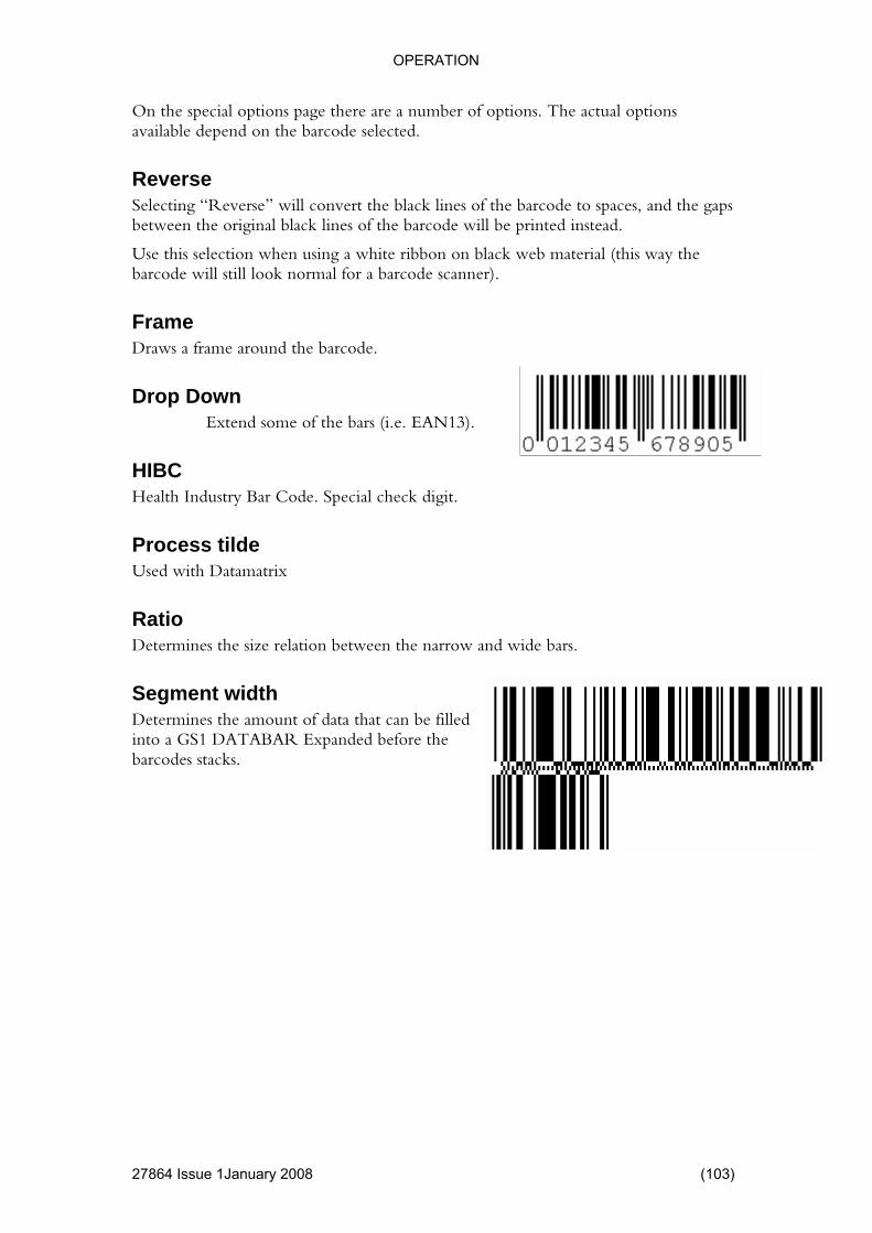
OPERATION
ry 2008 (103)
ons available depend on the barcode selected.
e to spaces, and the gaps
e will still look normal for a barcode scanner).
Frame e around the barcode.
Drop Down Extend some of the bars (i.e. EAN13).
Code. Special check digit.
ess tilde
arrow and wide bars.
Segment width Determines the amount of data that can be filled into a GS1 DATABAR Expanded before the barcodes stacks.
On the special options page there are a number of options. The actual opti
Reverse Selecting “Reverse” will convert the black lines of the barcodbetween the original black lines of the barcode will be printed instead.
Use this selection when using a white ribbon on black web material (this way the barcod
Draws a fram
HIBC Health Industry Bar
ProcUsed with Datamatrix
Ratio Determines the size relation between the n
27864 Issue 1Janua
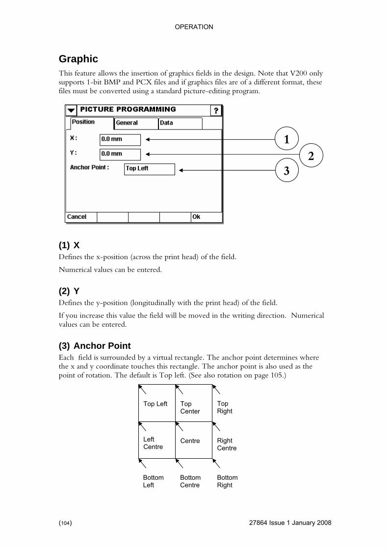
OPERATION
27864 Issue 1 January 2008
V200 only of a different format, these
files must be converted using a standard picture-editing program.
(1) X es the x-position (across the print head) of the field.
n (l
Numerical
(3) Anchor Point Each field is surrounded by a virtual rectangle. The anchor point determines where the x a y coordinate touches t ang e anchor point is also used as the point of rotation. The default is Top left. (See also rotation on page 105.)
Graphic This feature allows the insertion of graphics fields in the design. Note that supports 1-bit BMP and PCX files and if graphics files are
12
3
Defin
Numerical values can be entered.
(2) Y Defines the y-positio ongitudinally with the print head) of the field.
If you increase this value the field will be moved in the writing direction.values can be entered.
nd his rect le. Th
Bottom Left
Bottom Centre
Bottom Right
Right Centre
Top Left
Left Centre
Centre
Top Right
Top Center
(104)

OPERATION
4 Issue 1January 2008 (105)
(1) Use Original Size the picture size in pixels (hence no rescaling is done in printer).
the height of the graphics to be defined.
(3) Width aphics to be defined.
n Aspect Ratio
.
(5) Rotation The field can be rotated to 0, 90,180 and 270 degrees. Directions are stated as North, South, East and West. By pressing on a direction, a dropdown menu will appear and the user can then select the desired rotation. In combination with the anchor point (see page 104) you can rotate the field to suit requirements.
Always uses
(2) Height This allows
Numerical values can be entered.
This allows the width of the gr
Numerical values can be entered.
(4) MaintaiIf active, the relationship between the graphics width and height is constant.
Deselecting this feature allows the image to be stretched out of proportion
21
3
6
45
2786
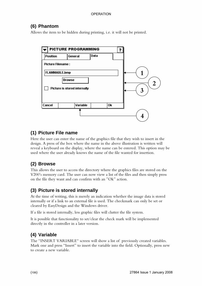
OPERATION
(6) Phantom
4 Issue 1 January 2008
Allows the item to be hidden during printing, i.e. it will not be printed.
Here the user can enter the name of the graphics file that they wish to insert in the ss of the box where the name in the above illustration is written will
n.
(2) Browse ectory where the graphics files are stored on the
imply press
data is stored le is used. The checkmark can only be set or
Design and the Windows driver.
ted ler in a later version.
(4) Variable The “INSERT VARIABLE“ screen will show a list of previously created variables. Mark one and press “Insert” to insert the variable into the field. Optionally, press new to create a new variable.
(1) Picture File name
design. A prereveal a keyboard on the display, where the name can be entered. This option may be used where the user already knows the name of the file wanted for insertio
This allows the user to access the dirV200’s memory card. The user can now view a list of the files and then son the file they want and can confirm with an ”Ok” action.
(3) Picture is stored internally At the time of writing, this is merely an indication whether the imageinternally or if a link to an external ficleared by Easy
If a file is stored internally, less graphic files will clutter the file system.
It is possible that functionality to set/clear the check mark will be implemendirectly in the control
3
1
2
4
(106) 2786
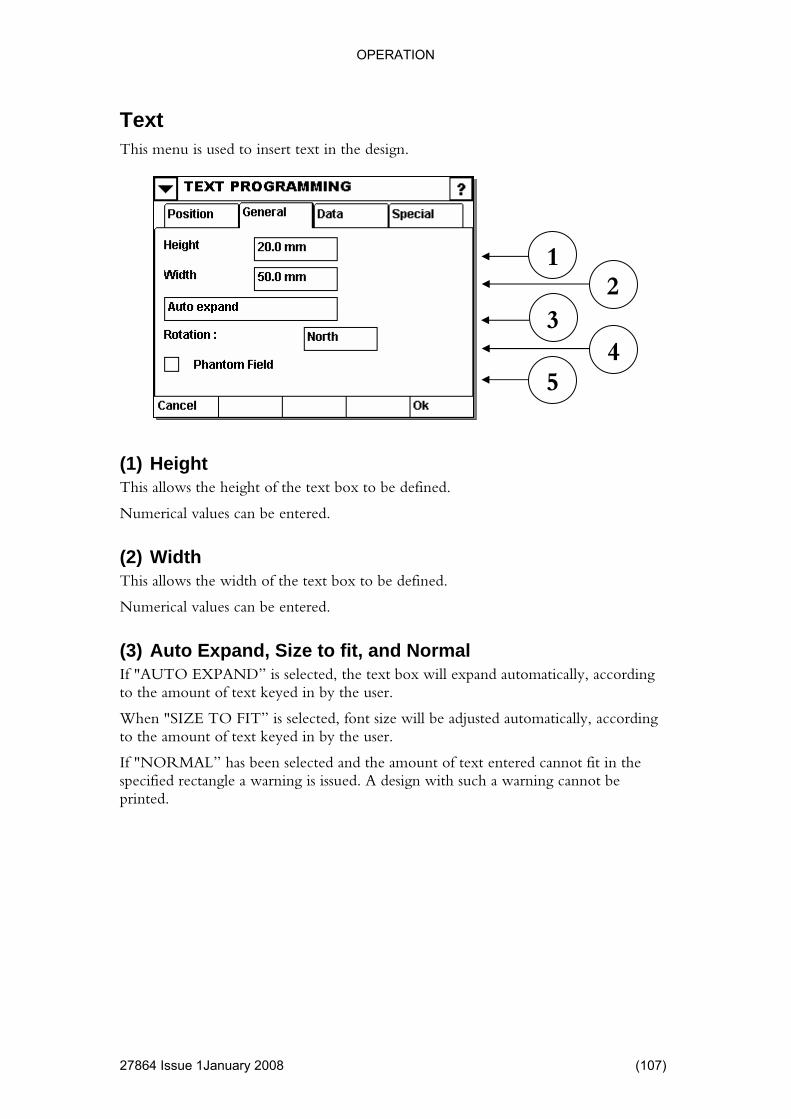
OPERATION
Text
4 Issue 1January 2008 (107)
This menu is used to insert text in the design.
the height of the text box to be defined.
(2) Width ed.
, and Normal y, according
cted, font size will be adjusted automatically, according to the amount of text keyed in by the user.
If "NORMAL” has been selected and the amount of text entered cannot fit in the specified rectangle a warning is issued. A design with such a warning cannot be printed.
1
(1) Height This allows
Numerical values can be entered.
This allows the width of the text box to be defin
Numerical values can be entered.
(3) Auto Expand, Size to fitIf "AUTO EXPAND” is selected, the text box will expand automaticallto the amount of text keyed in by the user.
When "SIZE TO FIT” is sele
23
54
2786
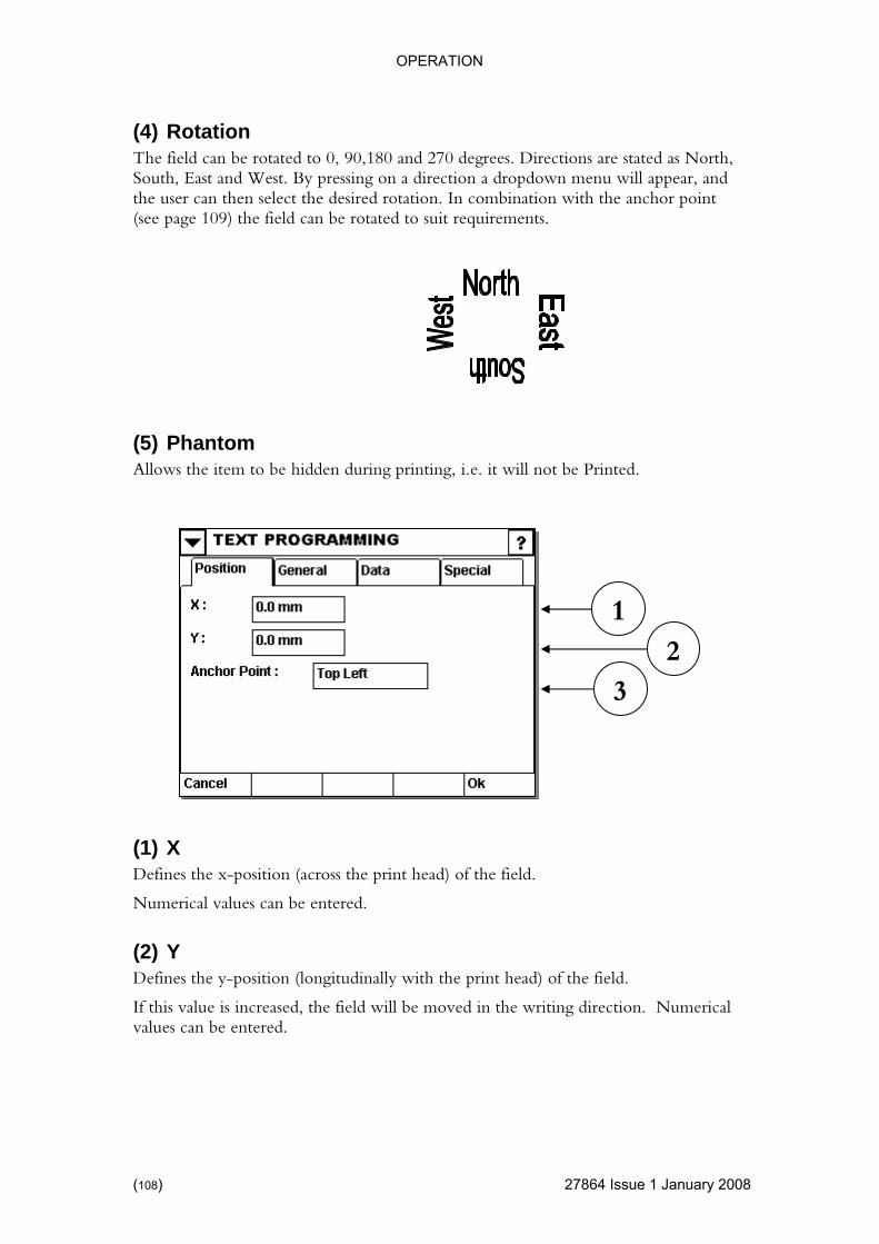
OPERATION
4 Issue 1 January 2008
d as North, appear, and
bination with the anchor point (see page 109) the field can be rotated to suit requirements.
(5) Phantom Allows the item to be hidden during printing, i.e. it will not be Printed.
(2) Y Defines the y-position (longitudinally with the print head) of the field.
If this value is increased, the field will be moved in the writing direction. Numerical values can be entered.
(4) Rotation The field can be rotated to 0, 90,180 and 270 degrees. Directions are stateSouth, East and West. By pressing on a direction a dropdown menu willthe user can then select the desired rotation. In com
(1) X Defines the x-position (across the print head) of the field.
Numerical values can be entered.
12
3
(108) 2786
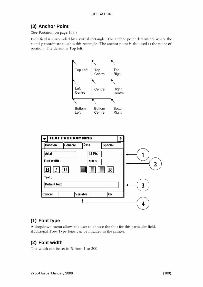
OPERATION
(3) Anchor Point
4 Issue 1January 2008 (109)
where the this rectangle. The anchor point is also used as the point of
rotation. The default is Top left.
A dropdown menu allows the user to choose the font for this particular field. Additional True Type fonts can be installed in the printer.
(2) Font width The width can be set in % from 1 to 200
(See Rotation on page 108.)
Each field is surrounded by a virtual rectangle. The anchor point determinesx and y coordinate touches
Bottom Left
Bottom Centre
Bottom Right
Right Centre
(1) Font type
2
3
1
4
Top Left
Left Centre
Centre
Top Right
Top Centre
2786

OPERATION
(3) Text Enter the actual text here. By pressing this field a keyboard will appear and the required text can be keyed in. Press “Ok” to exit.
here an already stored variable can be chosen, or a new one made by pressing “ NEW “.
Font Attributes The following options are available for manipulating the attributes of the font.
(4) Variable This will change to the screen “INSERT VARIABLE“ w
Convert text to bold
Convert text to italics
Underline text
Align text to left
Align text to centre
Align text to right
Inverse. All text is normally printed out against a plain background. Selecting this option will reverse the situation, printing out the background while leaving the text as empty space.
(110) 27864 Issue 1 January 2008

OPERATION
1January 2008 (111)
t (in mm) for the space between lines. This allows you to
cing
When activated, any line which contains just blanks, will be omitted from the design item.
This is particularly of use for address labels.
(1) Line spacing This provides an adjustmenmake lines closer together or further apart.
(2) Character spaThe distance between two characters can be set from 0 to 10.
(3) Omit Blank Lines
12
3
27864 Issue

OPERATION
Variables A design contains two basic components: Fields and variables. Variables must be used if the information in a field needs to be updated (either run time or at job load).
The display below shows a list of the possible variables:
Inserting variables If the user wishes to set up a new variable, they can do so using the New Variable menu. The user will then obtain a complete list of the various pieces of variable data that can be set up.
ld be noted enu can only be used for setting up the actual variable, it must sub ently be inserted in the desired field.
button for the variable type you wish to insert.
See page
It shou that this mand that sequ
Press the
Heading
Sequential 114
Real-Time 118
Shift Code 129
Prompted 131
Machine ID 133
Serial Variable 135
User ID 134
Database Extract 149
Database 145
Macro 138
Macro Output 144
(112) 27864 Issue 1 January 2008
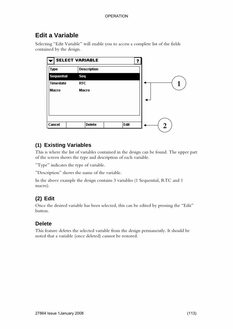
OPERATION
4 Issue 1January 2008 (113)
ble” will enable you to access a complete list of the fields contained by the design.
ed in the design can be found. The upper part
” indicates the type of variable.
tion” shows the name of the variable.
nd 1
dit g the “Edit”
Delete This feature deletes the selected variable from the design permanently. It should be noted that a variable (once deleted) cannot be restored.
Edit a Variable Selecting “Edit Varia
(1) Existing Variables This is where the list of variables containof the screen shows the type and description of each variable.
”Type
”Descrip
In the above example the design contains 3 variables (1 Sequential, RTC amacro).
(2) EOnce the desired variable has been selected, this can be edited by pressinbutton.
2
1
2786
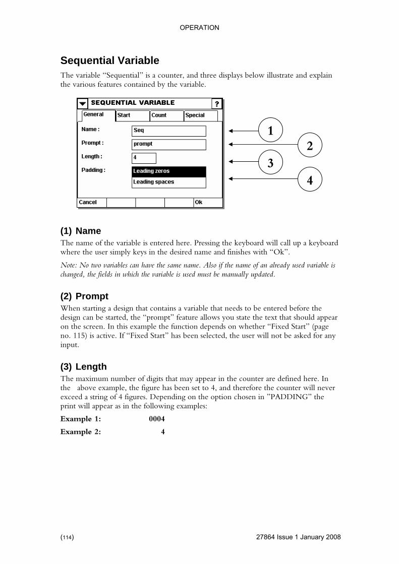
OPERATION
27864 Issue 1 January 2008
nd three displays below illustrate and explain the various features contained by the variable.
oard will call up a keyboard where the user simply keys in the desired name and finishes with “Ok”.
variables can have the same name. Also if the name of an already used variable is
n starting a design that contains a variable that needs to be entered before the design can be started, the “prompt” feature allows you state the text that should appear
. In this example the function depends on whether “Fixed Start” (page sked for any
h um number o igits that may appear in the counter are defined here. In
set to 4, and therefore the counter will never exceed a string of 4 figures. Depending on the option chosen in ”PADDING” the print will appear as in the following examples:
Example 1: 0004
Example 2: 4
Sequential Variable The variable “Sequential” is a counter, a
1 2
3 4
(1) Name The name of the variable is entered here. Pressing the keyb
Note: No twochanged, the fields in which the variable is used must be manually updated.
(2) Prompt Whe
on the screenno. 115) is active. If “Fixed Start” has been selected, the user will not be ainput.
(3) LengtThe maxim f dthe above example, the figure has been
(114)

OPERATION
(4) Paddin
4 Issue 1January 2008 (115)
whether or not to fill in ing. There are two options available:
ngth ing Spaces”
in example 2, which will simply leave a gap in front of the number instead of zeros.
(1) Fixed Start ype in the number from which the counter should start. In the example
rompt the
(2) Resume If resume is activated, the sequential variable will remember the last printed value and resume from that value the next time the design is printed. In the field where the start value is typed in, you can see the value at which the counter will resume.
g In connection with the above example, you can define hereall the spaces of the number str
Leading Zeros, or, Leading Spaces.
”Leading Zeros” fills in zeros in front of the count sequence fulfilling the ledefined. Thus “Leading Zeros” has been selected in example 1 and “Lead
1 2
The user can tabove the printer will start at 0. If fixed start is not active, the system will poperator for a start value.
2786
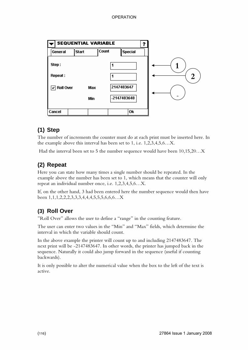
OPERATION
4 Issue 1 January 2008
above this interval has been set to 1, i.e. 1,2,3,4,5,6…X.
0,15,20…X
the et to 1, which means that the counter will only
idual number once, i.e. 1,2,3,4,5,6…X.
ence would then have been 1,1,1,2,2,2,3,3,3,4,4,4,5,5,5,6,6,6…X
e above example the printer will count up to and including 2147483647. The next print will be -2147483647. In other words, the printer has jumped back in the sequence. Naturally it could also jump forward in the sequence (useful if counting backwards).
It is only possible to alter the numerical value when the box to the left of the text is active.
(1) Step The number of increments the counter must do at each print must be inserted here. In the example
Had the interval been set to 5 the number sequence would have been 1
(2) Repeat Here you can state how many times a single number should be repeated. Inexample above the number has been srepeat an indiv
If, on the other hand, 3 had been entered here the number sequ
(3) Roll Over ”Roll Over” allows the user to define a “range” in the counting feature.
The user can enter two values in the “Min” and “Max” fields, which determine the interval in which the variable should count.
In th
2
�
3
1
(116) 2786
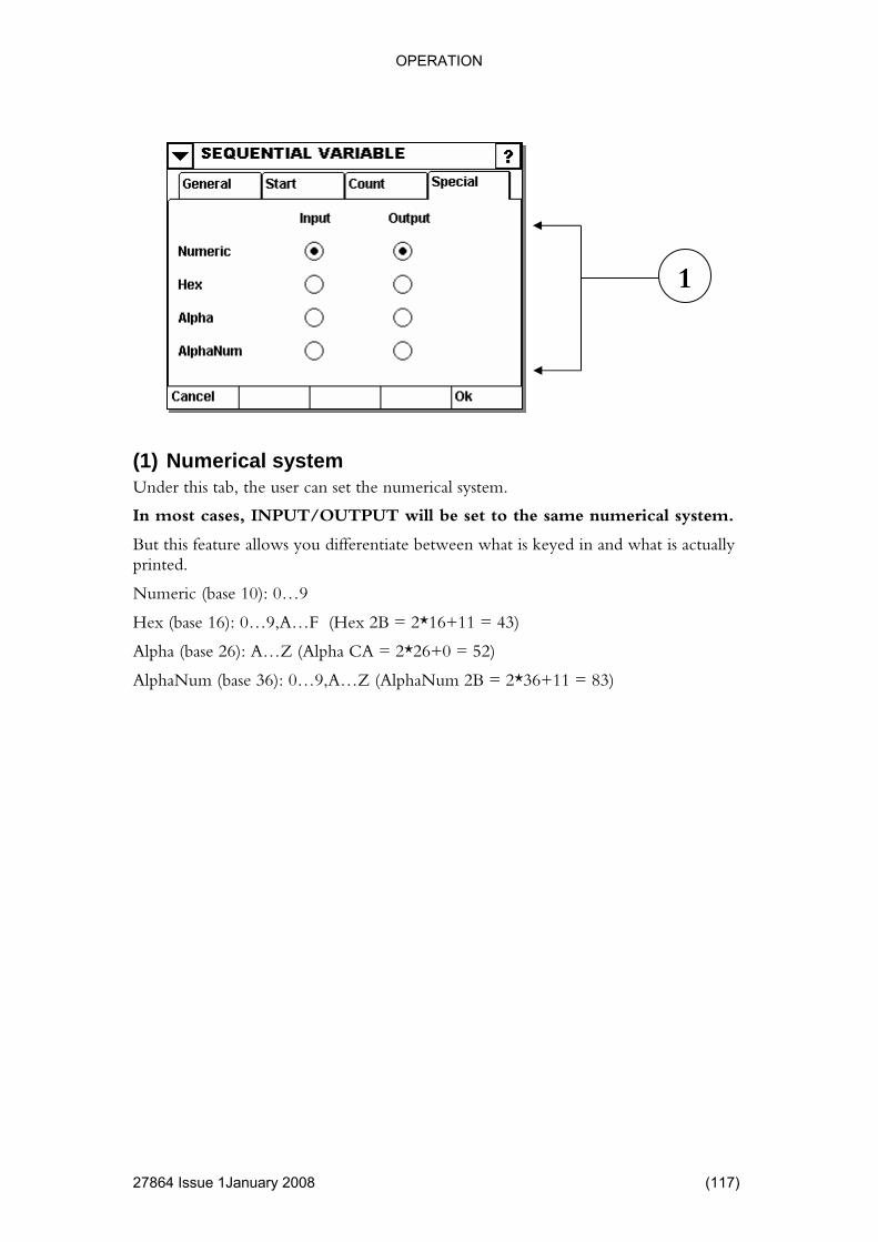
OPERATION
1January 2008 (117)
set to the same numerical system.
what is keyed in and what is actually
Hex (base 16): 0…9,A…F (Hex 2B = 2*16+11 = 43)
Alpha (base 26): A…Z (Alpha CA = 2*26+0 = 52)
AlphaNum (base 36): 0…9,A…Z (AlphaNum 2B = 2*36+11 = 83)
1
(1) Numerical system Under this tab, the user can set the numerical system.
In most cases, INPUT/OUTPUT will be
But this feature allows you differentiate betweenprinted.
Numeric (base 10): 0…9
27864 Issue
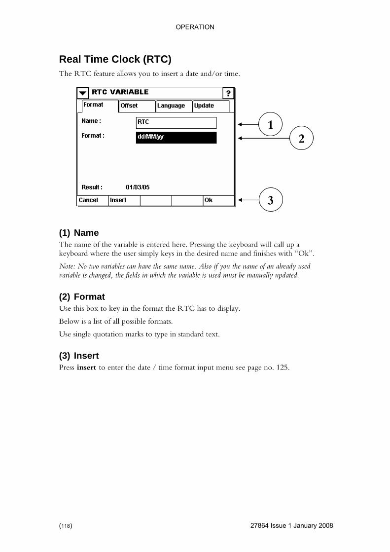
OPERATION
Real Time Clock (RTC)
27864 Issue 1 January 2008
The RTC feature allows you to insert a date and/or time.
l call up a keyboard where the user simply keys in the desired name and finishes with “Ok”.
variables can have the same name. Also if you the name of an already used must be manually updated.
x to key in the format the RTC has to display.
Use single quotation marks to type in standard text.
(3) Insert Press insert to enter the date / time format input menu see page no. 125.
1 2
3
(1) Name The name of the variable is entered here. Pressing the keyboard wil
Note: No twovariable is changed, the fields in which the variable is used
(2) Format Use this bo
Below is a list of all possible formats.
(118)
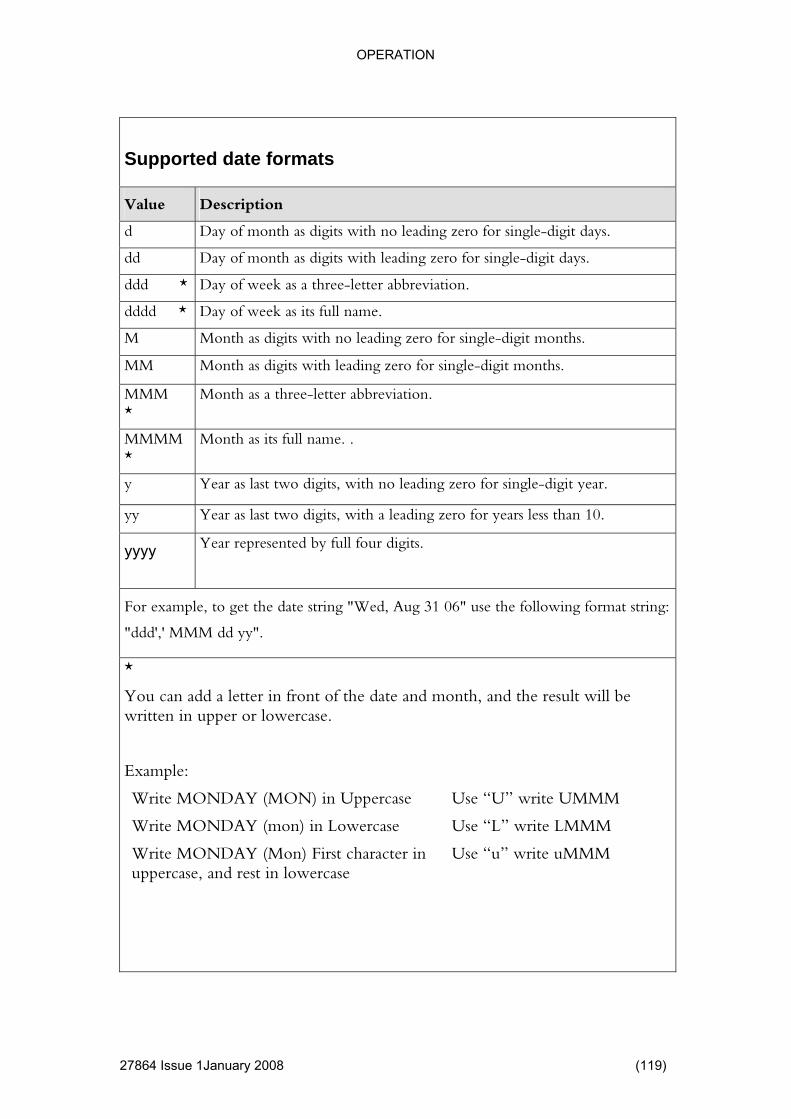
OPERATION
Supported date formats
Value Description
d Day of month as digits with no leading zero for single-digit days.
dd Day of month as digits with leading zero for single-digit days.
ddd * Day of week as a three-letter abbreviation.
dddd * Day of week as its full name.
M Month as digits with no leading zero for single-digit months.
MM Month as digits with leading zero for single-digit months.
MMM Month as a three-letter abbreviation. *
MMMM *
Month as its full name. .
y Year as last two digits, with no leading zero for single-digit year.
yy Year as last two digits, with a leading zero for years less than 10.
yyyy Year represented by full four digits.
For example, to get the date string "Wed, Aug 31 06" use the following format string:
"ddd',' MMM dd yy".
*
You can add a letter in front of the date and month, and the result will be written in upper or lowercase.
Example:
Write MONDAY (MON) in Uppercase Use “U” write UMMM
Write MONDAY (mon) in Lowercase Use “L” write LMMM
Write MONDAY (Mon) First character in Use “u” write uMMM uppercase, and rest in lowercase
27864 Issue 1January 2008 (119)

OPERATION
Supported time formats
Value Description
h Hours with no leading zero for single-digit hours; 12-hour clock
hh Hours with leading zero for single-digit hours; 12-hour clock
H Hours with no leading zero for single-digit hours; 24-hour clock
HH Hours with leading zero for single-digit hours; 24-hour clock
m Minutes with no leading zero for single-digit minutes
mm Minutes with leading zero for single-digit minutes
s Seconds with no leading zero for single-digit seconds
ss Seconds with leading zero for single-digit seconds
t One character time marker string, such as A or P
tt Multi character time marker string, such as AM or PM
For example, to get the time string "11:29:40 PM", use the following picture string: "hh':'mm':'ss tt"
Suppo cial formats rted spe
Value Description
doy Day of year
Y Day of year (always three digits) DO
woy Week of year
WOY Week of year (always two digits)
Dow Day of week (Sunday=0, Monday=1…Saturday=6).
(120) 27864 Issue 1 January 2008

OPERATION
1January 2008 (121)
ge To define the date or month with letters, this menu allows a choice of various languages.
1
(1) Output Langua
English Spain Finland Italy
Example November Noviembre Marraskuu Nobembre
27864 Issue
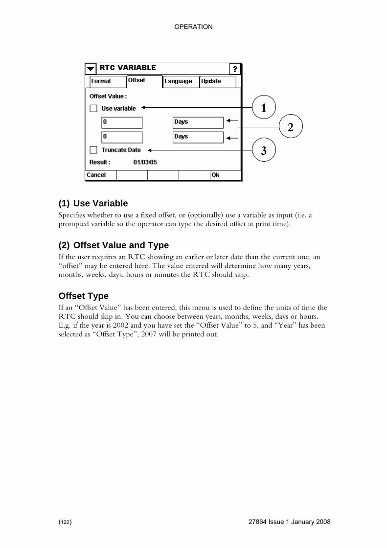
OPERATION
4 Issue 1 January 2008
offset, or (optionally) use a variable as input (i.e. a .
ier or later date than the current one, an be entered here. The value entered will determine how many years,
If an “Offset Value” has been entered, this menu is used to define the units of time the RTC should skip in. You can choose between years, months, weeks, days or hours. E.g. if the year is 2002 and you have set the “Offset Value” to 5, and “Year” has been selected as “Offset Type”, 2007 will be printed out.
1
(1) Use Variable Specifies whether to use a fixedprompted variable so the operator can type the desired offset at print time)
(2) Offset Value and Type If the user requires an RTC showing an earl“offset” may months, weeks, days, hours or minutes the RTC should skip.
Offset Type
3
2
(122) 2786

OPERATION
(3) Truncate Date
4 Issue 1January 2008 (123)
2005
Wanted: 1 month offset date.
when an illegal date (like 31st
um day in the specific month.
Truncate Date” in inactive, the date enters the next month.
cate Date is only active for offsets with months and years.
are applied in the following order:
Year
tes.
rent day = 31.01.2005, plus 1 month = 31.02.2005
05 is an invalid date, it is truncated to
Date: 28.02.2005
(2) Truncate day inactive Since 31.02.2005 is an invalid date, it goes to
Date: 03.03.2005
Example: Actual date 31.01.
2 1
RTC variable always uses the correct numbers of days in a specific month.
The “Truncate Date” settings determine the behaviourof February) is reached.
If “Truncate Date” is active, the day is set to the maxim
If “
Trun
The different types of offset
Month
Week, Day, Hours and Minu
Example: Cur
(1) Truncate Day active: Since 31.02.20
2786
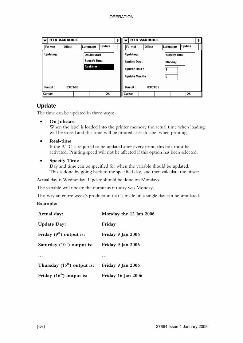
OPERATION
uary 2008
• On Jobstart
ting.
x must be selected.
ariable should be updated. the offset:
y is Wednesday. Update should be done on Mondays.
e will update th onday.
is made on a single day can be simulated.
Example:
e 12 Jan 2006
Update The time can be updated in three ways:
When the label is loaded into the printer memory the actual time when loading will be stored and this time will be printed at each label when prin
• Real-time If the RTC is required to be updated after every print, this boactivated. Printing speed will not be affected if this option has been
• Specify Time Day and time can be specified for when the vThis is done by going back to the specified day, and then calculate
Actual da
The variabl e output as if today was M
This way an entire week’s production that
Actual day: Monday th
Update Day: Friday
2006
ut i 2006
… …
Thursday (15th) output is: Friday 9 Jan 2006
Friday (16th) output is: Friday 16 Jan 2006
Friday (9th) output is: Friday 9 Jan
Saturday (10th) outp s: Friday 9 Jan
(124) 27864 Issue 1 Jan

OPERATION
This menu can be used instead of typing the data format from the keyboard.
4 Issue 1January 2008 (125)
) and then:
Press Data Format Menu
ng pre-defined formats:
ate has en used as a basis: 02-01-2003)
of the t and long formats please see page 119
1
git): 01
it): 3
it): 03
2003
02
Month (Long format): January
Day (Short format): Thu
Day (Long format): Thursday
The Menu can be reached by pressing “Insert” (see page no. 118
Insert Data Format Menu This menu allows the user to choose between the followi
(The following d be
To alter the case shor
Month (1 Digit):
Month (2 Di
Year (1 Dig
Year (2 Dig
Year (4 Digit):
Day (1 Digit): 2
Day (2 Digit):
Month (Short format): Jan
2786
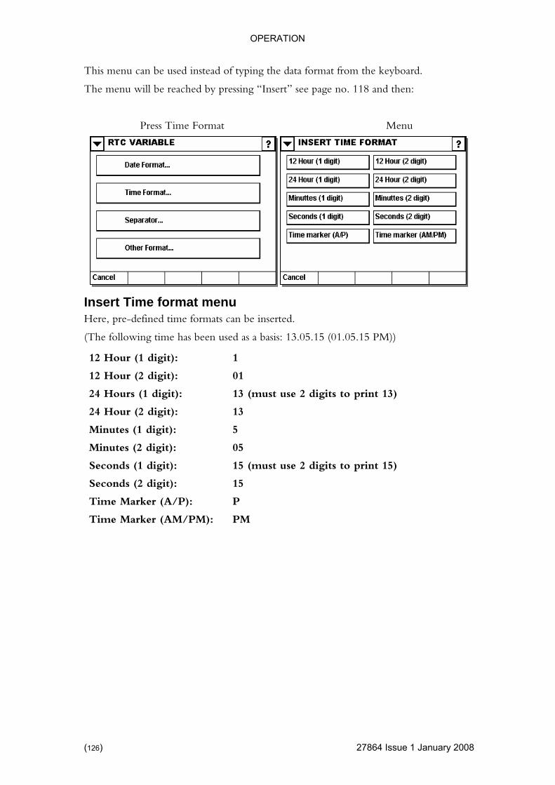
OPERATION
This menu can be used instead of typing the data format from the keyboard.
uary 2008
The menu will be reached by pressing “Insert” see page no. 118 and then:
Press Time Format Menu
time formats can be inserted.
e has be sed as a basis: 13.05.15 (01.05.15 PM))
1
it): 01
git): 13 (must use 2 digits to print 13)
it):
it): 5
05
15 (must use 2 digits to print 15)
Seconds (2 digit): 15
Time Marker (A/P): P
Time Marker (AM/PM): PM
Insert Time format menu Here, pre-defined
(The following tim en u
12 Hour (1 digit):
12 Hour (2 dig
24 Hours (1 di
24 Hour (2 dig 13
Minutes (1 dig
Minutes (2 digit):
Seconds (1 digit):
(126) 27864 Issue 1 Jan
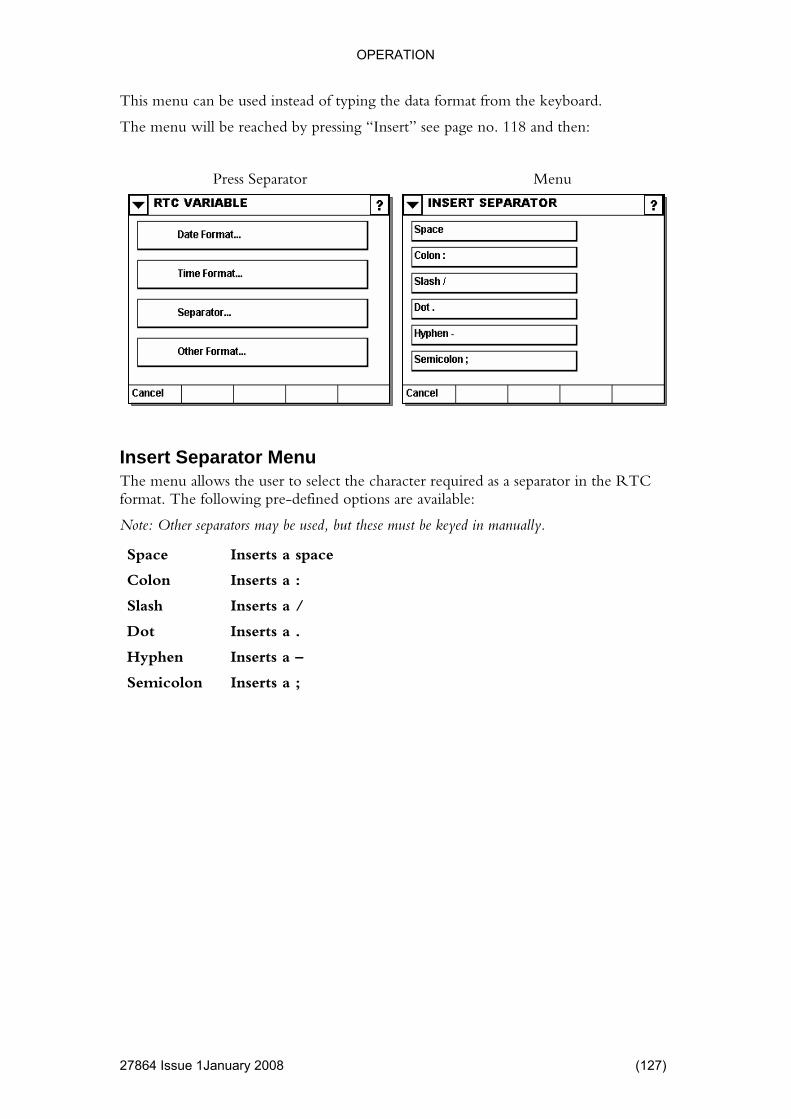
OPERATION
This menu can be used instead of typing the data format from the keyboard.
ry 2008 (127)
The menu will be reached by pressing “Insert” see page no. 118 and then:
Press Separator Menu
The menu allows the user to select the character required as a separator in the RTC t. The fined options are available:
but these must be keyed in manually.
ace a space
a :
a /
Dot Inserts a .
Hyphen Inserts a –
Semicolon Inserts a ;
Insert Separator Menu
forma following pre-de
Note: Other separators may be used,
Sp Inserts
Colon Inserts
Slash Inserts
27864 Issue 1Janua
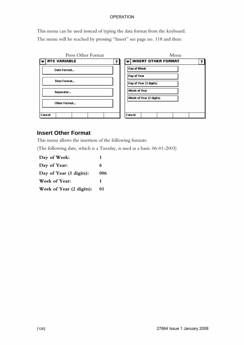
OPERATION
This menu can be used instead of typing the data format from the keyboard.
uary 2008
The menu will be reached by pressing “Insert” see page no. 118 and then:
Press Other Format Menu
ows the inse on of the following formats:
y, is used as a basis: 06-01-2003)
1
6
Day of Year (3 digits): 006
Week of Year: 1
Week of Year (2 digits): 01
Insert Other Format This menu all rti
(The following date, which is a Tuesda
Day of Week:
Day of Year:
(128) 27864 Issue 1 Jan

OPERATION
4 Issue 1January 2008 (129)
al time (e.g. t “Day Shift” between 8:00 and 16:00). The shift code variable is updated in real
irst shift that es not verify that all timeslots is defined. (If
no matching shift is found, the output is blank).
rd will call up a e the user simply keys in the desired name and finishes with “Ok”.
same name. If the name of an already used variable is
(2) Shift List This is a list of currently defined shifts.
Pressing the “Add” button allows the creation of a new shift definition.
Shift Code A shift code variable is used to print a line of text that depends on the actuPrintime.
Note: The variable does not verify that no shifts overlap. (If two shifts overlap, the fmatches the current time is selected). The variable do
1
2
(1) Name The name of the variable is entered here. Pressing the keyboakeyboard wher
Note: No two variables can have the changed, the fields in which the variable is used must be manually updated.
2786

OPERATION
This menu allows the user to define the text for one particular time slot.
4 Issue 1 January 2008
d.
HH and MM define the actual time and stands for hours and minutes, respectively.
example shown, the start time has been set at 08.00 and applies to every day of
t also select c day as end time.
efine the actual time and stands for hours and minutes, respectively.
ery day of
(3) Shift Text The actual “Shift Code” should be entered here. The text entered is the text that will be printed in the time period set. Pressing the field in which ”Day Shift” appears will call up the keyboard and the user can then key in another text.
(1) From Set the time slots start time. Pressing “All days” specifies that all days should be treated the same way. Alternatively, the individual days of the week can be selecte
In the the week.
(2) To Set the time slot end time. If a specific day is selected as start time, you musa specifi
HH and MM d
In the example shown, the stop time has been set to 16.00 and applies to evthe week.
3
2
1
(130) 2786
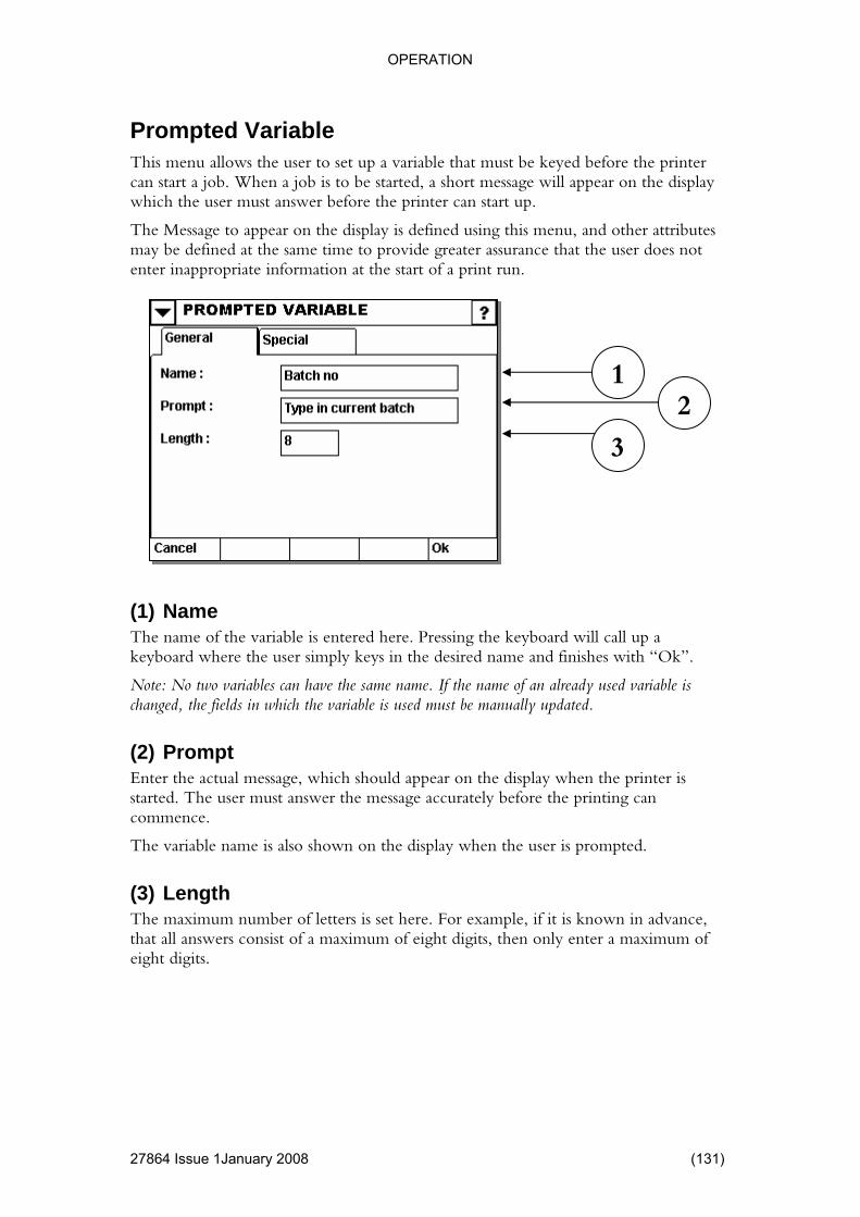
OPERATION
4 Issue 1January 2008 (131)
e printer essage will appear on the display
er attributes
enter inappropriate information at the start of a print run.
rd will call up a ere the user simply keys in the desired name and finishes with “Ok”.
d variable is .
d appear on the display when the printer is user must answer the message accurately before the printing can
ble name is also shown on the display when the user is prompted.
(3) Length The maximum number of letters is set here. For example, if it is known in advance, that all answers consist of a maximum of eight digits, then only enter a maximum of eight digits.
Prompted Variable This menu allows the user to set up a variable that must be keyed before thcan start a job. When a job is to be started, a short mwhich the user must answer before the printer can start up.
The Message to appear on the display is defined using this menu, and othmay be defined at the same time to provide greater assurance that the user does not
(1) Name The name of the variable is entered here. Pressing the keyboakeyboard wh
Note: No two variables can have the same name. If the name of an already usechanged, the fields in which the variable is used must be manually updated
(2) Prompt Enter the actual message, which shoulstarted. The commence.
The varia
1 2
3
2786

OPERATION
4 Issue 1 January 2008
(1) Numeric advance, that only numerical values should be entered, this option
(2) AlphaNum In cases where it is necessary to enter both digits and letters, this option should be selected.
If it is known in should be selected. It will then be impossible to key in letters.
1
2
(132) 2786
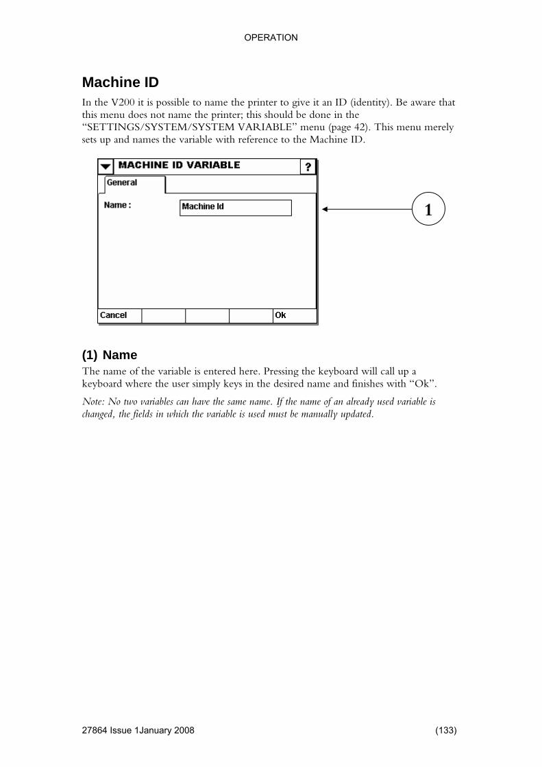
OPERATION
4 Issue 1January 2008 (133)
n ID (identity). Be aware that
(page 42). This menu merely sets up and names the variable with reference to the Machine ID.
oard will call up a keyboard where the user simply keys in the desired name and finishes with “Ok”.
Note: No two variables can have the same name. If the name of an already used variable is changed, the fields in which the variable is used must be manually updated.
Machine ID In the V200 it is possible to name the printer to give it athis menu does not name the printer; this should be done in the “SETTINGS/SYSTEM/SYSTEM VARIABLE” menu
1
(1) Name The name of the variable is entered here. Pressing the keyb
2786
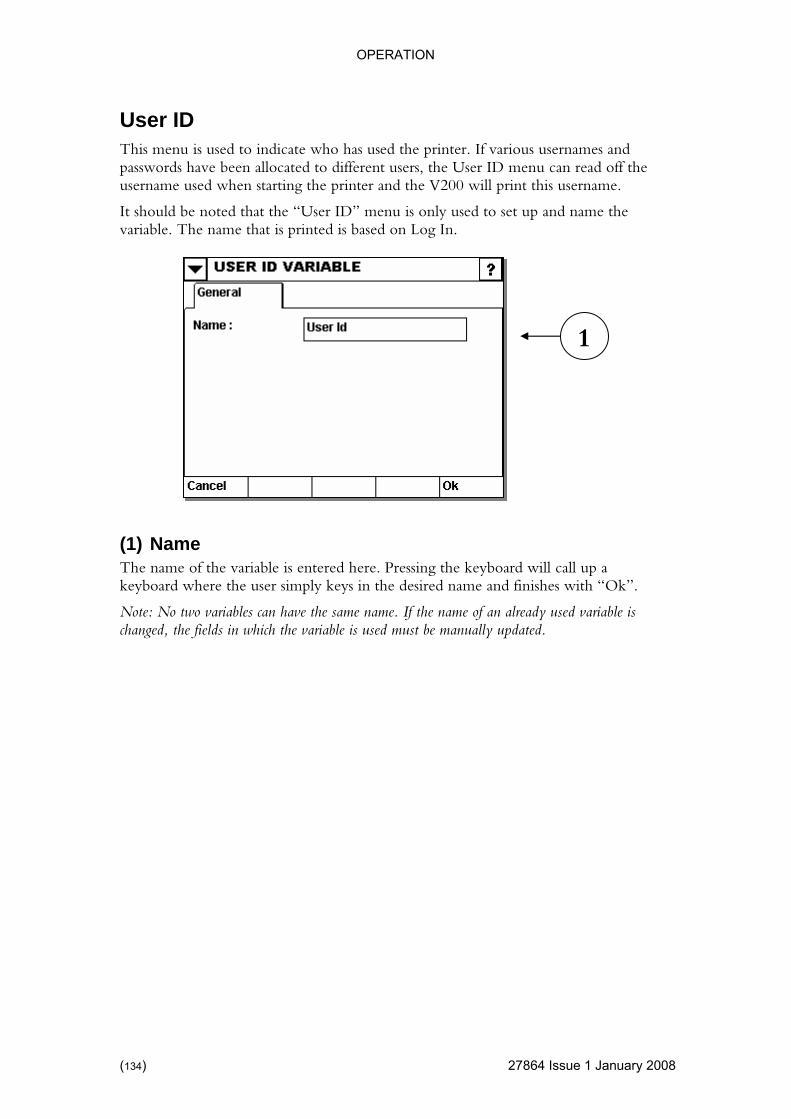
OPERATION
27864 Issue 1 January 2008
es and n read off the sername.
only used to set up and name the variable. The name that is printed is based on Log In.
rd will call up a keyboard where the user simply keys in the desired name and finishes with “Ok”.
Note: No two variables can have the same name. If the name of an already used variable is changed, the fields in which the variable is used must be manually updated.
User ID This menu is used to indicate who has used the printer. If various usernampasswords have been allocated to different users, the User ID menu causername used when starting the printer and the V200 will print this u
It should be noted that the “User ID” menu is
1
(1) Name The name of the variable is entered here. Pressing the keyboa
(134)

OPERATION
4 Issue 1January 2008 (135)
u is used for setting up a data transmission of variables from an external PC to the printer.
oard will call up a keyboard where the user simply keys in the desired name and finishes with “Ok”.
riables can have the same name. If the name of an already used variable is iable is used must be manually updated.
(2) Updating p in f
le is updated and the printing will continue with this value until a new value is sent.
pacity
(NoBuffer):
4) First Time On ariable does not
5) Weight Input:
Choosing this setting shows the “Buffer size” input field where you set the delay. For each print pulse the internal buffer (FIFO) is updated. No prints are made until the internal buffer is filled (because the product associated with the weight is not yet under the printer).
Serial Variable This men
1 2
3 4
(1) Name The name of the variable is entered here. Pressing the keyb
Note: No two vachanged, the fields in which the var
Can be set u ive different ways:
1) On Request: When the value is sent the variab
2) Each Print: A new value has to be send for each print (buffer ca1000 Values).
3) Each print A new value has to be sent for each print.
ly: One (and only one) variable is received. The vchange until the print job is loaded again.
Use this setting where the input is generated by a scale and the input needs to be delayed a certain amount of prints.
2786

OPERATION
(3) Use Default The user can enter a stored variable as default setting, by markThe chosen
ing the field and write “start contents” this function is only available when using
“on request “.
protocol used by the controller. Note that the input definition only affects the serial interface and not the LAN interface.
Fou
• is the key code of the character. Use this form to he keyboard (like SOH, ETB, STX and ETX)
•
•
the text and the info that the ce sends.
entered as a hexadecimal.
in the following format:
SerialVar=[STX]VarName[ETX],[STX]Value[ETX][ETB]
d by the following input definition:
2\v06\x03\x17
02)
led “Serial”)
03)
act match)
\x02 (STX = Hex 02)
\x03 (ETX = Hex 03)
\x17 (ETB = Hex 17)
Note: If you use the software libraries, the transfer is UNICODE, as opposed to the given example (which is in ANSI).
(4) Input definition This field can be used if the input device (i.e. scale) is not compatible with the
r types of entries are supported
\xNN: A single character. NNinput a character not found on t
\vNN: NN characters to be printed
\dNN: NN characters as “don’t care”
• Clear text: There must be a direct match betweendevi
Note: NN is to be considered a number in the range from zero to 255As an example, number 77 (decimal) should be typed in as 4D (hex).
Example 1:
The V SERIES CONTROLLER expects data
[SOH]Fill
This can be achieve
\x01FillSerialVar=\x02Serial\x03,\x0
Explanation:
\x01 (SOH = Hex 01)
FillSerialVar= (Must make an exact match)
\x02 (STX = Hex
Serial (We assume that this particular variable is cal
\x03 (ETX = Hex
, (Must make an ex
\v06 (The input data is exactly (Hexadecimal)6 characters)
(136) 27864 Issue 1 January 2008

OPERATION
To make the input definition UNICODE you need to put an \x00 after each character.
0=\x00\x0\x00a\x00l\x00\x03\x00,\x00\x02\x00\v01\x00\v01\x00\v01\x00\v
he libraries you cannot not verifyl if you typed in the input definition incorrectly.
(Result: \x01\x00F\x00i\x00l\x00l\x00S\x00e\x00r\x00i\x00a\x00l\x00V\x00a\x00r\x02\x00S\x00e\x00r\x00i01\x00\x03\x00\x17\x00).
Also if the input definition fails it will be ignored, therefore, if the above has been tried using t
27864 Issue 1January 2008 (137)

OPERATION
Macro Variable A macro is a special kind of variable that can be utilized when you nethan the standard variable supplies. The macro variable contains a progenvironment in which you
ed more power ramming
can transfer information between other variables and perform (advanced) calculations.
(1) Fixed Length ax characters for the variable.
The name of the variable is entered here. Pressing the keyboard will call up a simply keys in the desired name and finishes with “Ok”.
already used variable is ble is used must be manually updated.
e
fault.
t like a sequential variable).
This check mark is enabled as default.
(5) Macro Definition In this field you type in some lines of code that determines the behaviour of the macro. See the following pages for how to make a macro definition.
Length: M
Pad with characters to fill out spaces until max length is reached.
(2) Name
keyboard where the user
Note: No two variables can have the same name. If the name of anchanged, the fields in which the varia
(3) Update Real TimIf checked the variable is updated whenever there is some idle time.
This check mark is enabled as de
(4) Update Each Print If checked the variable is updated once after each print. (Jus
2 3
4
5
1
(138) 27864 Issue 1 January 2008
OPERATION
Variables in a macro The macro programming language recognises six different kind of variables:
• can only be s than (<) rted:
ad by the macro to determine if it is a sequential update (performed e (when ever there is some idle time
ontains the name of the printer e of the user that is logged in.
in month
• ables already created in the current design macro. A t curly
• nformation. string variables
treated as
• er values. integer
t are otherwise
• f floating named f0 to
int variables (f0 to f19) are initialised when a print job is started, but are otherwise treated as a “static local variable”
• Output variables: Used to place “the result” of the macro. This is required for a macro to do anything useful. You can use a Macro output variable to store the result or you can use a special name called output. Example: output=”The meaning of life is 42”.
System variables: These variables are controlled by the system andread from the macro. A system variable is identified by the use of lesand greater than (>) signs. The following system variables are suppo<seq>: Reonce after each print) or a real time updatin the system).
<machineid>: C<userid>: User nam<HH>: Current hour <mm>: Current minute
d <ss>: Current secon<dd> Current day<dow> Current day of week <MM>: Current month <yyyy>: Current year
Printer variables: This relates to variyou are editing. Generally these variables can only be read from the printer variable is identified by the use of left curly brace ({) and righbrace (}). Example: {name of some variable}
String variables: Internal macro variable used for storage of text iThe macro has access to 20 string variables named s0 to s19. All(s0 to s19) are initialised when a print job is started, but are otherwisea “static local variable”
Integer variables: Internal macro variable used for storage of integThe macro has access to 20 integer variables named d0 to d19. Allvariables (d0 to d19) are initialised when a print job is started, butreated as a “static local variable”.
Floating point variables: Internal macro variable used for storage opoint values. The macro has access to 20 floating point variables f19. All floating po
27864 Issue 1January 2008 (139)
OPERATION
Flow of execution control
ro programming language contains statements to control the flow of
• ere in the tered. The
first typing a colon : “ :MyLabel”
• e macro
• ther true or false. Only
Example2: 2==3 yields false (two is not equal to 3) • if then: Tests a Boolean expression and executes the then statement depending
est. Example: if d1>1 then goto MyLabel
CaHo
• an internal nything unless you store a
e types (like string and integer) the variables type.
nd vice versa 3
Yields s1 to have the value “123” • tors work on integers and floating point
increments d1 with 1) • nate two strings using the + operator.
• ors:
• mainder of an integer division: Example: 17 % 3 = 2 (since 17-5*3=2)
• Formatting output: Use the format function to make the result look the way you like it. The format function uses the standard c format function so any c programmer should be familiar to this function Example: s1 = format(”num:%.4d, float:%.3f”,12, 4.345234) Yields s1 = “num:0012, float:4.345”
How to control the program flow:
The macexecution:
Labels: A label is some kind of bookmark that you can insert anywhmacro definition. A label does not consume CPU time when encounlabel statement required for branching. A label is inserted byfollowed by a name. Example
goto; Moves the point of execution to a label anywhere in thdefinition. Example: goto MyLabel
Boolean test: compares two values and yields einumbers can be tested. Use the operators >, < and == (double equal sign) to perform the test Example1: 1<2 yields true (1 is less than 2)
on the t
lculations w to perform calculus
Equal operator: Used to store a result in a variable (that can bevariable or an output variable). A macro does not do aresult somewhere. When mixing two variablmacro tries to translate the source variables data to the destinationThus allowing us to insert an integer value in a text variable aExample d1 = “123 some text” Yields d1 to be the value 12Example s1 = d1
+-*/: Standard mathematical operavariables. Example d1 = d1 + 1 (
String concatenation: ConcateExample: s1=s1 + s2;
Boolean operatLogical AND (&): Example 1 & 0 = false Logical OR: (|): Example 1 | 0 = true Logical XOR: (^): Example 1^0 = true
Modulo: (%): Returns the re
(140) 27864 Issue 1 January 2008
OPERATION
Macro text examples //A remark is ignored when the macro executes. //Text written after two slashes ’//’ is considered // How do I work with strings s0 = ”String” s1 = ”A ss2 = ”A 2nd sting variable” s3 = ”text1” // Text with forced newline cs4 = ”text1\nText2\nte // You can also use s5 to s1s19 = // Howd0 = 0 d1 = 100 d2 = 30// You d19 = 1 f0 = 0.005
f2 = 2.345 // You cf19 = 19.43223
a remark.
tring is created with quotation mark”
style ”\n” xt3\\”
8 ”Last string variable”
do I work with integers
0 can also use d3 to d18 3000
f1 = 1.234
an also use f3 to f18
// This is how I get a result
amples A remark is ignored when the macro executes.
after two slashes ’//’ is considered a remark.
// How do I work with ’if/then’ if d1 > 20 then d1 = 1 if d1 < 1.05 then d1 = 1.00
s5 = s3 + s4 output = s5 // output: text1text1\nText2\ntext3\\
Macro if/then ex
//Text written
27864 Issue 1January 2008 (141)

OPERATION
Macro arithmetic examples
Macro label examples
amples ,<,>
iable, an equal sign, a source and
ptionally an operator and a second source
//Or
and label example
o I declare a new label
// How to jump to a label
//this will keep jumping until d1 is 19
utput the result
output = d1
point support +, -, * and / f1 = 3.45 * 4.56 f2 = 3.45 / 2.00 // Integers supports in addition &, |, ^ and % d2 = d1 % 7
d3 = d1 % d0
Macro goto examples
Macro calculus ex//Standard arithmetic: +,-,*,/,=//A statement consists of a destination
//var
//o
d2 = d1
d1 = d1 + 1
// gotod1 = 0
// How d
:MyLabel
//taste of arithmetic
d1 = d1 + 1
if d1 < 19 then goto MyLabel
// How to o
// floating
(142) 27864 Issue 1 January 2008
OPERATION
Macro converting examples cimal value from another variable
d1 = {RTC_dd}
tialises a string variable
//check if we are done
nt digit
10
//prepares d1 for next loop
an Arab number
characters may not be seen here if this editor cannot
cters
"?"
"?"
"?"
if d2==5 then s2 = "?"
if d2==6 then s2 = "`"
if d2==7 then s2 = "´"
if d2==8 then s2 = "^"
//Import a de
//Ini
s1 = ""
:loop
if d1=0 then goto done
//gets the least significa
d2 = d1 %
d1 = d1 / 10
//maps the digit to
//The correct Arab
//display the chara
if d2==0 then s2 =
if d2==1 then s2 =
if d2==2 then s2 =
if d2==3 then s2 = "?"
if d2==4 then s2 = "?"
27864 Issue 1January 2008 (143)

OPERATION
Macro Output Variable
4 Issue 1 January 2008
A macro output variable can be used to store a result from a macro.
oard will call up a keyboard where the user simply keys in the desired name and finishes with “Ok”.
Note: No two variables can have the same name. If the name of an already used variable is changed, the fields in which the variable is used must be manually updated.
1
(1) Name The name of the variable is entered here. Pressing the keyb
(144) 2786
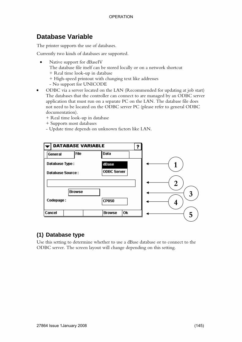
OPERATION
Database Variable
4 Issue 1January 2008 (145)
ses are supported.
• a network shortcut
• g at job start) DBC server
n a separate PC on the LAN. The database file does he ODBC server PC (please refer to general ODBC
+ Real time look-up in database + Supports most databases - Update time depends on unknown factors like LAN.
(1) Database type Use this setting to determine whether to use a dBase database or to connect to the ODBC server. The screen layout will change depending on this setting.
The printer supports the use of databases.
Currently two kinds of databa
Native support for dBaseIV The database file itself can be stored locally or on
database + Real time look-up in + High-speed printout with changing text like addresses - No support for UNICODE
ODBC via a server located on the LAN (Recommended for updatinThe databases that the controller can connect to are managed by an Oapplication that must run onot need to be located on tdocumentation).
1
2 3
4
5
2786
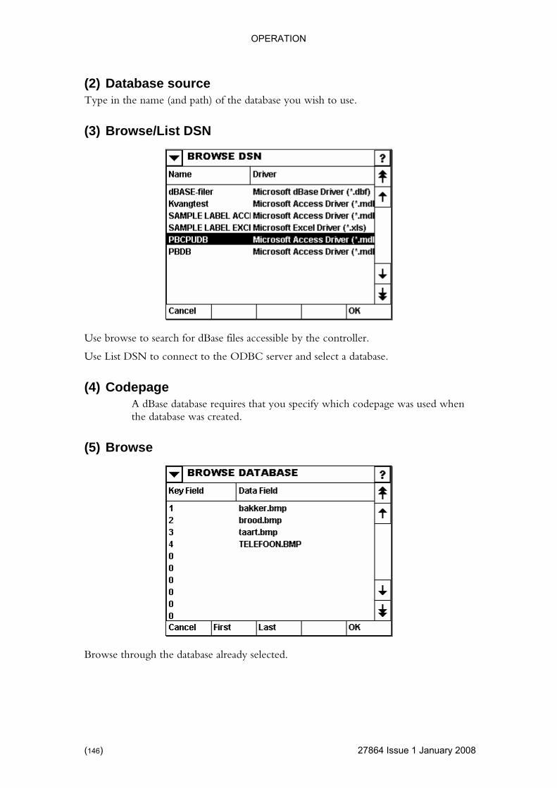
OPERATION
(2) Database source Type in the name (and path) of the database you wish to use.
(3) Browse/List DSN
arch for dBase files accessible by the controller.
Use Li
dBase database requires that you specify which codepage was used when the database was created.
(5) Browse
Use browse to se
st DSN to connect to the ODBC server and select a database.
(4) Codepage A
Browse through the database already selected.
(146) 27864 Issue 1 January 2008
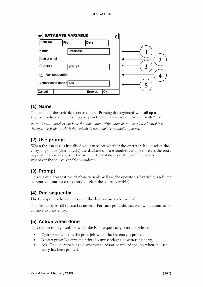
OPERATION
1January 2008 (147)
p a keyboard where the user simply keys in the desired name and finishes with “Ok”.
les can have the same name. If the name of an already used variable is
When the database is initialised you can select whether the operator should select the t or (alternatively) the database can use another variable to select the entry
perator. (If variable is selected
he v
(5) ne This option is only available when the Run sequentially option is selected.
• Quit print: Unloads the print job when the last entry is printed • Restart print: Restarts the print job (must select a new starting entry) • Ask: The operator is asked whether to restart or unload the job when the last
entry has been printed.
1 2
3 4
5
(1) Name The name of the variable is entered here. Pressing the keyboard will call u
Note: No two variabchanged, the fields in which the variable is used must be manually updated.
(2) Use prompt
entry to printo print. If a variable is selected as input the database variable will be updatedwhenever the source variable is updated.
(3) Prompt This is a question that the database variable will ask the oas input you must use this entry to select the source variable).
(4) Run sequential Use this option when all entries in the database are to be printed.
T first entry is still selected as normal. For each print, the database will automaticallyance to next entry. ad
Action when do
27864 Issue

OPERATION
4 Issue 1 January 2008
identifier is used as the key field.
f available fields is automatically updated to reflect the currently selected
ata nt is located.
dated to reflect the currently selected
ith the currently selected options.
Note: It is highly recommended to use the Database Extract variable (when multiple columns are required) instead of defining multiple database variables. This is due to the fact that for every (dBase) database variable, the entire database is loaded into RAM and there is no point in loading the same database several times.
1
(1) Key Given an entry value the database searches the key field for a match. Usually a unique
The list odatabase.
(2) DThis is the column where the data required to pri
The list of available fields is automatically updatabase.
(3) Field Type Shows the data field type (Text or Floating point).
(4) Add this field Use this shortcut to quickly add a Database Extract variable (page 149).
The Database Extract variable is automatically filled in w
2 3
4
(148) 2786

OPERATION
Database Extract Variable
1
4 Issue 1January 2008 (149)
oard will call up a keyboard where the user simply keys in the desired name and finishes with “Ok”.
variables can have the same name. If the name of an already used variable is
variable is connected to.
(3) Data Field n where the data required to print is located.
dated to reflect the currently selected database.
(4) Field Type Shows the data field type (Text or Floating Point).
(1) Name The name of the variable is entered here. Pressing the keyb
Note: No twochanged, the fields in which the variable is used must be manually updated.
(2) Source The source database variable that the Database Extract
This is the colum
The list of available fields is automatically up
2 3
4
2786
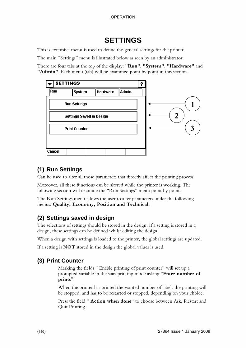
OPERATION
SETTINGS
27864 Issue 1 January 2008
e printer.
.
ardware" and "Admin". Each menu (tab) will be examined point by point in this section.
g process.
Moreover, all these functions can be altered while the printer is working. The “Run Settings” menu point by point.
ollowing al.
The selections of settings should be stored in the design. If a setting is stored in a can be defined whilst editing the design.
When gs are updated.
If a set T
This is extensive menu is used to define the general settings for th
The main “Settings” menu is illustrated below as seen by an administrator
There are four tabs at the top of the display: "Run", "System", "H
1 2
3
(1) Run Settings Can be used to alter all those parameters that directly affect the printin
following section will examine the
The Run Settings menu allows the user to alter parameters under the fmenus: Quality, Economy, Position and Technic
(2) Settings saved in design
design, these settings
a design with settings is loaded to the printer, the global settin
ting is NO stored in the design the global values is used.
(3) P a
variable in the start printing mode asking “Enter number of prints”.
When the printer has printed the wanted number of labels the printing will be stopped, and has to be restarted or stopped, depending on your choice.
Press the field “ Action when done“ to choose between Ask, Restart and Quit Printing.
rint Counter Marking the fields ” Enable printing of print counter” will set upprompted
(150)

OPERATION
Run Run Settings Quality
4 Issue 1January 2008 (151)
tabs.
ally affect should be noted that other parameters such as “Economy”
can also influence quality.
The illustration shows how the "Run Settings” display is divided up into
The “Quality” tab allows the alteration of those parameters that will normthe quality of printing. It
2 3
1
4 6
Quality settings for CM-Type
5 2
1
6 Quality settings for V100-Type
2786

OPERATION
08
t head prints. It is recommended to set this
dependent on the type of material being printed upon, and the type of ribbon used.
y ribbon is used, it may be necessary to increase the contrast, also note int head can be considerably reduced.
100 and V400)
h the label design.
hip and used
The preheat function make it possible to add or remove a part of the power calculation (temperature), which is necessary to use for printing the next dot.
This is can be used to make a final print quality adjustment, in accordance with the needs (speed, web surface condition etc.).
Quality settings for V400 -Type
2 1
(1) Contrast (CM, V100 and V400)
Controls the temperature at which the prinbetween 80%-100%. The higher the value, the hotter the temperature used by the print head to print. The contrast required is largely
If a low qualitthat the life of the pr
(2) Preheat (CM, V
The preheat settings can be used to increase / decrease the heat to the print head as additional adjustment range to the Contrast setting.
Theory:
During printing the single dots will be heated up in accordance wit
Every time a dot has been fired, this will be stored in a history memory cfor the calculation of the next print.
5 4
6
(152) 27864 Issue 1 January 20
OPERATION
(3) Slope Type (CM)
Controls the acceleration/deceleration of the ribbon motor. The acceleratiodeceleration is determined by the speed of the web; A higher web speeand smooth
n/ d yields a slow
acceleration, whereas a low web speed yields an almost instantaneous
speed and
f printing ation) and possibly ending up with a broken ribbon,
For cases like this, set it to manual and type in the maximum web speed in the edit just below.
ection, and hence allows
pact the print quality, but in reality the transfer of ink to the web is often improved and the total print quality is improved.
speeds above 700 mm/second, it is recommended to test if enabling ves the print quality.
(5) Print Speed 400)
To do this press the “default” button once.
Notice that the button is now reversed
When the default button is reversed press the setting you wish to reset.
If the default button is accidentally pushed, press it again to deselect the button.
acceleration.
When slope type is set to auto, the printer will monitor the current webcalculate an appropriate acceleration.
Under some circumstances, it is not possible to measure the web speed (iduring the web’s acceler
box that appears
(4) Fast Mode (CM and V400)
Fast mode actually reduces the resolution in the printing dirthe system to print in excess of 1000 mm/second.
Reducing the resolution can im
When printing at fast mode impro
(V100 and V
Use this setting to define the printing speed.
(6) Default The default button allows the reset of a single setting to the factory default.
27864 Issue 1January 2008 (153)
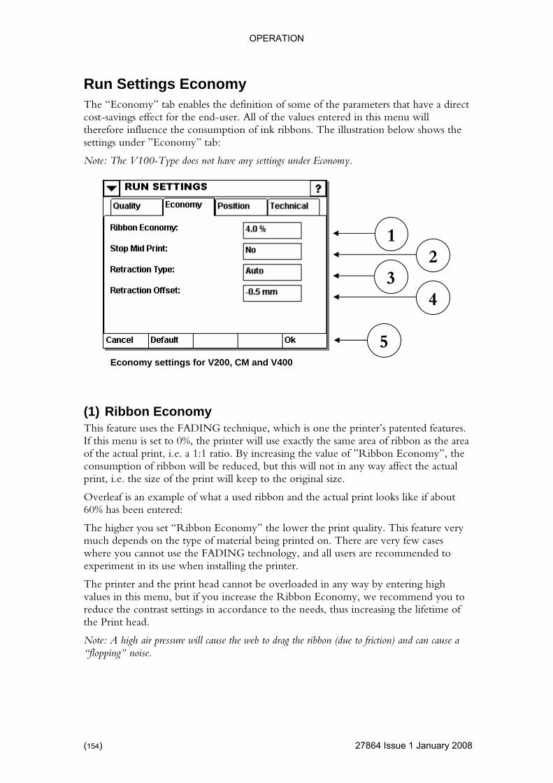
OPERATION
27864 Issue 1 January 2008
s that have a direct ill
sumption of ink ribbons. The illustration below shows the
Note: The V100-Type does not have any settings under Economy.
one the printer’s patented features. on as the area
i.e. a 1:1 ratio. By increasing the value of ”Ribbon Economy”, the the actual
ature very cases
annot use the FADING technology, and all users are recommended to
nd the print head cannot be overloaded in any way by entering high values in this menu, but if you increase the Ribbon Economy, we recommend you to reduce the contrast settings in accordance to the needs, thus increasing the lifetime of the Print head.
Note: A high air pressure will cause the web to drag the ribbon (due to friction) and can cause a “flopping” noise.
Run Settings Economy The “Economy” tab enables the definition of some of the parametercost-savings effect for the end-user. All of the values entered in this menu wtherefore influence the consettings under ”Economy” tab:
(1) Ribbon Economy This feature uses the FADING technique, which is If this menu is set to 0%, the printer will use exactly the same area of ribbof the actual print, consumption of ribbon will be reduced, but this will not in any way affect print, i.e. the size of the print will keep to the original size.
Overleaf is an example of what a used ribbon and the actual print looks like if about 60% has been entered:
The higher you set “Ribbon Economy” the lower the print quality. This femuch depends on the type of material being printed on. There are very fewwhere you cexperiment in its use when installing the printer.
The printer a
1 2
3 4
5 Economy settings for V200, CM and V400
(154)
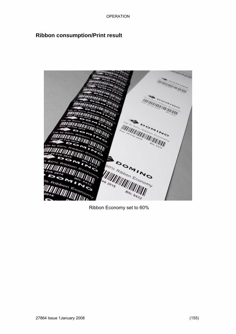
OPERATION
Ribbon consumption/Print result
4 Issue 1January 2008 (155)
Ribbon Economy set to 60%
2786

OPERATION
27864 Issue 1 January 2008
aced widely apart. The resultant space straightforward waste of ribbon.
See the below example:
ze of the hat there is a
lour ribbon between the upper part (BAKED BEANS) and the lower part (Lot Number)
etween ped, i.e. no
uld occur middle of the print, this may be due to having selected the
“YES” mode and the print head and the ribbon does not have sufficient time to lift elerate and decelerate. The user should therefore be aware that
s could be due to having
s at very high w millimetres too far with a
speeds.
ll back the her set to OFF, MANUAL or AUTOMATIC.
If it is set to OFF, there will be no reverse feed of the ribbon.
If it has been set to Manual, the user must define the number of millimetres the printer should pull back the ribbon. It is recommended to measure the desired pull back before entering a value in order to avoid entering an overly high value causing prints to overlap on the ribbon.
(2) Stop Mid Print It might be that the design contains text lines spbetween the lines is a
BAKED BEANS The bracket is related to the siprint and it is obvious that tgreat waste of co
Lot Numb321556464
er
ANS
er 321556464
ANS
BAKED BE
Lot Numb
BAKED BE
Lot Number
If “Stop Mid Print” is set to “YES”, the printer’s print head will be raised b“BAKED BEANS” and “Lot Number” and ribbon feed will also be stopribbon is wasted.
We recommend this feature be always set to “YES”. If quality problems shoat high speeds in the
up/return or to accreduced print quality in the middle of the design at high speedset this option to “YES”.
Retraction Type This menu is extremely important in reducing consumption of ribbon.
A thermo-transfer printer (of the type that V200 is) normally workspeeds, and in many cases the ribbon will be pulled a feresultant waste of ribbon. To compensate for this, the V200 can pull the ribbon either way and thus compensate for the extra ribbon that can get pulled at high
The ”RETRACTION” feature defines how much the printer should puribbon. This feature can eit
(156)
OPERATION
If this item is set to Automat , you must enter a ”Retraction Off Set”, which is used ic
”Retraction Offset” is recommended to be –0.5.
Retraction Offset
be set in
s been set to “Automatic”, “Retraction Offset” must be set in
t of a single setting to the factory default.
When the default button is reversed press the setting you wish to reset.
If the default button is accidentally pressed, press it again to deselect the button.
to fine-tune the ribbon pull back.
Retraction Length This menu being displayed on the screen depends on how “Retraction Type” has been set.
If “Retraction Type” has been set to “off”, the field is hidden.
If “Retraction Type” has been set to “Manual”, “Retraction Length” must this field.
If “Retraction Type” hathis menu.
(2) Default The default button allows the rese
To do this press the “default” button once.
Notice that the button is now reversed
27864 Issue 1January 2008 (157)
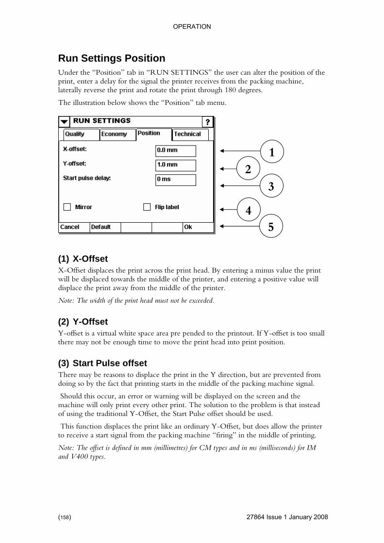
OPERATION
27864 Issue 1 January 2008
e position of the the packing machine,
rough 180 degrees.
The illustration below shows the “Position” tab menu.
ead. By entering a minus value the print ng a positive value will
int away from the middle of the printer.
is too small .
nted from ine signal.
d the only print every other print. The solution to the problem is that instead
of using the traditional Y-Offset, the Start Pulse offset should be used.
This function displaces the print like an ordinary Y-Offset, but does allow the printer to receive a start signal from the packing machine “firing” in the middle of printing.
Note: The offset is defined in mm (millimetres) for CM types and in ms (milliseconds) for IM and V400 types.
Run Settings Position Under the “Position” tab in “RUN SETTINGS” the user can alter thprint, enter a delay for the signal the printer receives fromlaterally reverse the print and rotate the print th
1 2
3
4
(1) X-Offset
5
X-Offset displaces the print across the print hwill be displaced towards the middle of the printer, and enteridisplace the pr
Note: The width of the print head must not be exceeded.
(2) Y-Offset Y-offset is a virtual white space area pre pended to the printout. If Y-offsetthere may not be enough time to move the print head into print position
(3) Start Pulse offset There may be reasons to displace the print in the Y direction, but are prevedoing so by the fact that printing starts in the middle of the packing mach
Should this occur, an error or warning will be displayed on the screen anmachine will
(158)
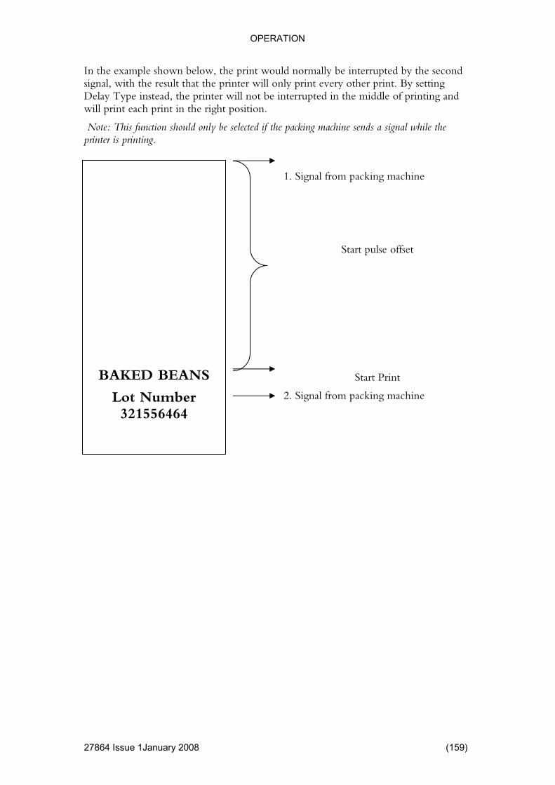
OPERATION
In the example shown below, the print would normally be interrupted by the second signal, with the result that the printer will only print every other print. ByDelay Type instead, the printer will
setting not be interrupted in the middle of printing and
nction should only be selected if the packing machine sends a signal while the printer is printing.
1. Signal from packing machine
Start pulse offset
Start Print
2. Signal from packing machine
will print each print in the right position.
Note: This fu
BAKED BEANS
Lot Number 321556464
27864 Issue 1January 2008 (159)

OPERATION
(4) Flip label
4 Issue 1 January 2008
ge of the print terial.
The total 180 degrees rotation is produced when the Mirror and Flip label function are activated at the same time.
To do this press the “default” button once.
Notice that the button is now reversed
When the default button is reversed press the setting you wish to reset.
If the default button is pressed accidentally, press it again to deselect the button.
Mirror Both the “Flip label” and the “Mirror” feature produces a mirror imaand may be used to advantage if printing on the inside of transparent ma
The Flip label function produces a mirror image around the X-axis and the Mirror function produces a mirror image around the Y-axis.
Original Mirrored
Flipped Flipped and mirrored
(5) Default The default button allows you to reset a single setting to the factory default.
(160) 2786
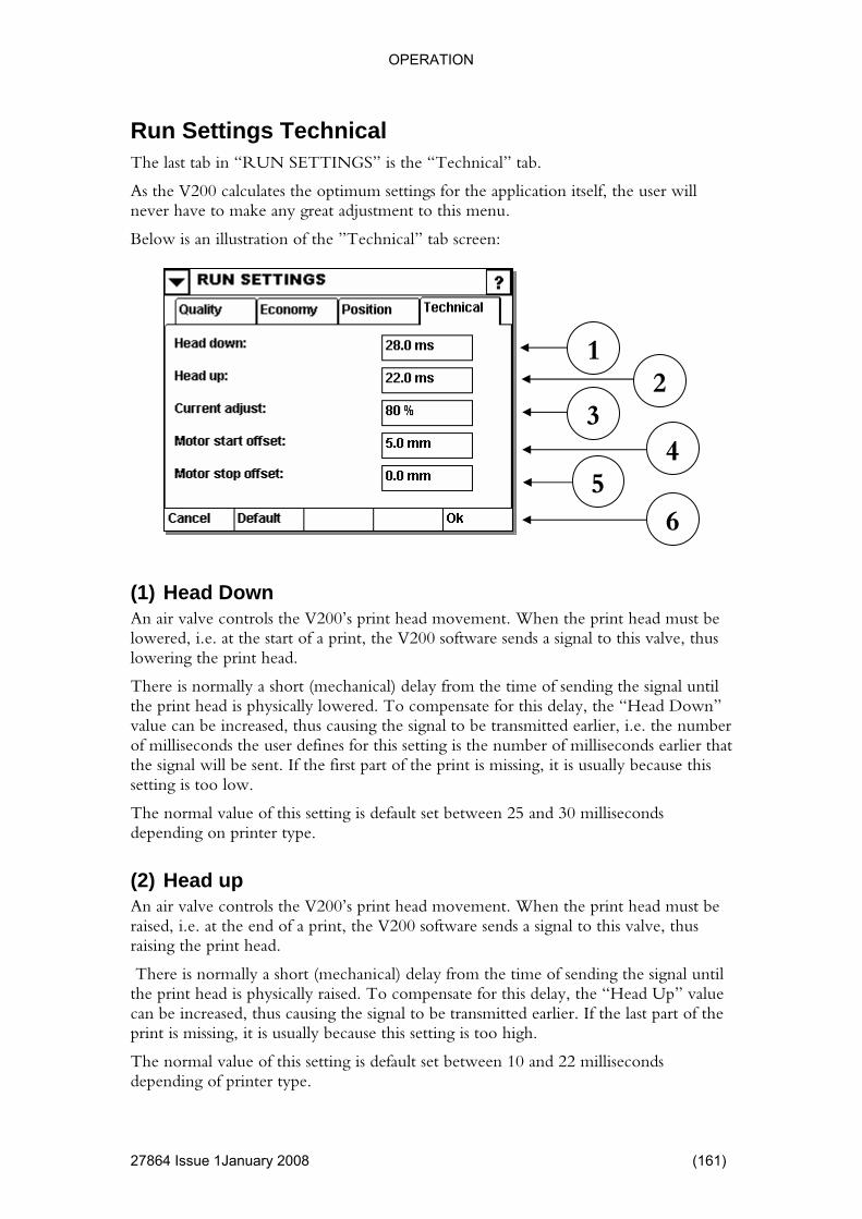
OPERATION
Run Settings Technical
4 Issue 1January 2008 (161)
the application itself, the user will is menu.
Below is an illustration of the ”Technical” tab screen:
d must be lve, thus
signal until compensate for this delay, the “Head Down”
ier, i.e. the number defines for this setting is the number of milliseconds earlier that
e print is missing, it is usually because this w.
ds
d must be
There is normally a short (mechanical) delay from the time of sending the signal until the print head is physically raised. To compensate for this delay, the “Head Up” value can be increased, thus causing the signal to be transmitted earlier. If the last part of the print is missing, it is usually because this setting is too high.
The normal value of this setting is default set between 10 and 22 milliseconds depending of printer type.
The last tab in “RUN SETTINGS” is the “Technical” tab.
As the V200 calculates the optimum settings for never have to make any great adjustment to th
1 2
3
(1) Head Down An air valve controls the V200’s print head movement. When the print healowered, i.e. at the start of a print, the V200 software sends a signal to this valowering the print head.
There is normally a short (mechanical) delay from the time of sending thethe print head is physically lowered. To value can be increased, thus causing the signal to be transmitted earlof milliseconds the userthe signal will be sent. If the first part of thsetting is too lo
The normal value of this setting is default set between 25 and 30 millisecondepending on printer type.
(2) Head up An air valve controls the V200’s print head movement. When the print hearaised, i.e. at the end of a print, the V200 software sends a signal to this valve, thus raising the print head.
6 5
4
2786
OPERATION
(3) Current adjust This item allows the adjustment of the power to the stepper motor pIf the stepper motor is having problems pulling the ribbon, this may be dueinsufficient current to the motor, and the value should
ulling the ribbon. to
be increased. At high speeds it
h current. If
ing.
Note: In the vast majority of cases it is not necessary to adjust the current. g is 80%
on relative quality the ribbon should be moving when the
ead is lowered a
most applications. At extremely high speeds (+1000millimetres/second) or printing on rough material like paper, it may be
this value.
n relative to bbon stops at
ribbon to be e print head
eing printed will occur. By bbon will be increased. The recommended
s item is 0millimetres, and seldom needs to be adjusted by the user. At ough material like
this setting very slightly.
efault.
To do this press the “default” button once.
Notice that the button is now reversed
When the default button is reversed, press the setting you wish to reset.
If the default button is accidentally pressed, press it again to deselect the button.
may be necessary to increase the current to the stepper motor.
If the printer is running very slowly, the stepper motor will not need mucthis value is set too high relative to the speed, the stepper motor will start to vibrate, resulting in small horizontal lines being printed across the direction of writ
The recommended settin
(4) Motor start on offset Here the user can define when the step motor should start pulling the ribbto the start of the print. To get the best print head is lowered. If the ribbon is not mowing when the print hblack line may occur at the start of the print.
The default setting is sufficient in
advantageous to increase
Note: V100 types do not have this setting.
(5) Motor stop offset This setting defines when the stepper motor must stop pulling the ribbowhen the print head is raised. This best quality is achieved when the riexactly the same moment that the print head is raised, or by allowing themoving when the print head is raised. If the ribbon is not moving while this still lowered, undesirable smudging of the material bincreasing this value the pull on the risetting for thiextremely high speeds (+1000millimetres/second) or printing on rpaper, it may be beneficial to increase
(6) Default The default button allows you to reset a single setting to the factory d
(162) 27864 Issue 1 January 2008

PART 4 : MAINTENANCE & FAULT FINDING
CONTENTS
Page
164
.........164
......... 165
......... 167
......... 168
......... 170
.........170
.........171
172
......... 174
......... 190
.........192
.........208
......... 210
.........210
.........211
212
.........213
......... 215
......... 234
......... 235
......... 247
SERIAL COMMUNICATION................................................................... 247
UPGRADING.......................................................................................... 247
PRINTER................................................................................................ 247
RIBBON BREAKS .................................................................................. 250
PREVENTATIVE MAINTENANCE .........................................................Maintenance Scheme..................................................................
LOADING RIBBON........................................................................CLEANING THE PRINT HEAD .....................................................REPLACING THE PRINT HEAD ...................................................TENSION CONTROL ....................................................................
Lubrication of the re-winder .........................................................Ribbon un-wind roll adjustment ...................................................Ribbon rewind roll adjustment ..............................................................
DATA MANAGEMENT ..................................................................UPGRADING FIRMWARE ............................................................
Data Management.......................................................................Upgrade ......................................................................................
FAULT FINDING............................................................................Sensor test ..................................................................................Sensor test on a V200.................................................................Sensor test on a V100..........................................................................Sensor test on a V400.................................................................
LIST OF ERRORS.........................................................................ELECTRICAL ................................................................................PRINT QUALITY AND PRINT HEAD ............................................NETWORK ....................................................................................
27864 Issue 1January 2008 (163)

MAINTENANCE & FAULT FINDING
PREVENTATIVE MAINTENANCE
Maintenance Scheme
• Check and Clean Print head (each time the ribbon is replaced or at least once a
• on is tracking through the cassette correctly. (Pull the reasing across
• that the
y high, it may be because the Print head for this
•
• Check condition of Platen/Roller rubber. Clean or replace if necessary. The
• Check for wear or internal debris
ion between the printer and controller must be firmly connected
• are smooth
•
• essary
• Check condition of carriage drive belt and associated components, pulleys, bearings, retainers and shafts
• Check air cylinder
• Check brake for wear.
Quick/regular checks
day)
Check that the Ribbribbon through by hand and visually check to see if the ribbon is cthe width of the ribbon)
Check that Contrast/speed settings are site standard. This will ensureprint remains at good quality, and may also highlight any potential problems. For example, if the contrast is unusuallneeded cleaning and the contrast had been set high to compensate
Check air is set to the recommended pressure
platen rubber needs to be smooth, flat and free from debris
• The connectbefore the power is switched on.
Monthly Checks Check condition of the Ribbon Guide Rollers. Check bearings
Check tension setting of Ribbon un-winder brake
Check clutch pad, and replace if nec
(164) 27864 Issue 1 January 2008
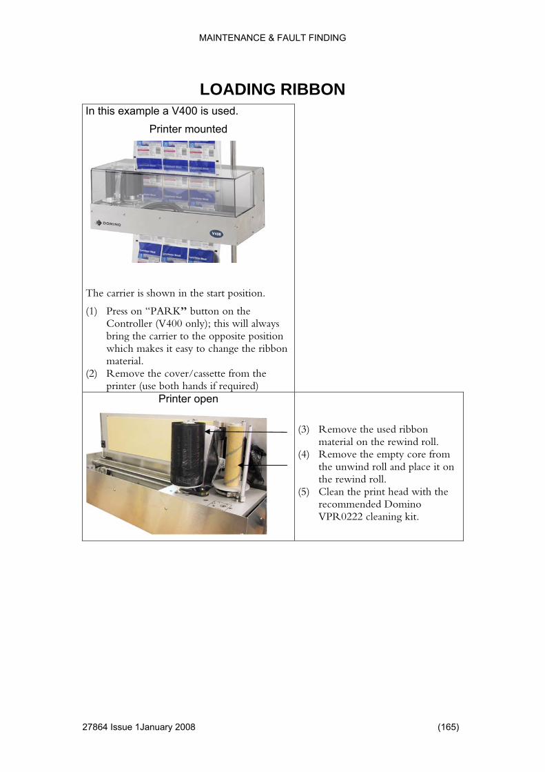
MAINTENANCE & FAULT FINDING
4 Issue 1January 2008 (165)
ON LOADING RIBBIn this example a V400 is used.
Printer mounted
The carrier is shown in the start position.
(1) Press on “PARK” button on the Controller (V400 only); this will always bring the carrier to the opposite position which makes it easy to change the ribbon material.
(2) Remove the cover/cassette from the printer (use both hands if required)
Printer open
(3) Remove the used r ibbon
material on the rewind roll. (4) Remove the empty core from
the unwind roll and place it on the rewind roll.
(5) Clean the print head with the recommended Domino VPR0222 cleaning kit.
2786
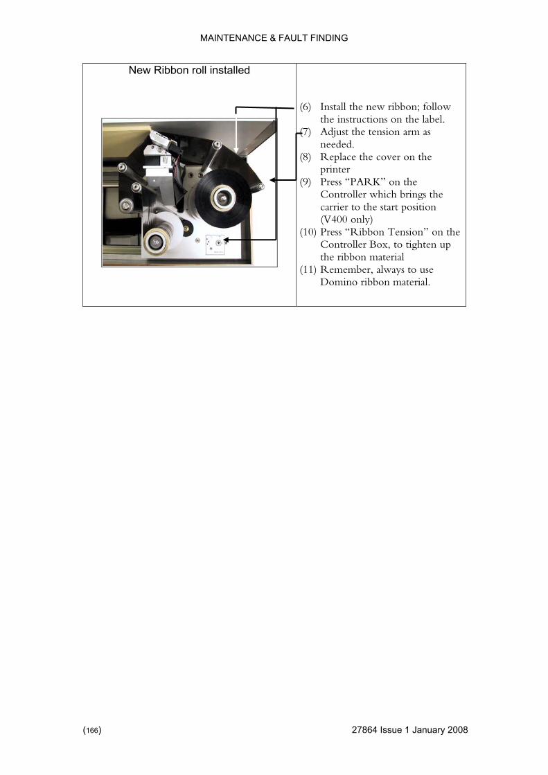
MAINTENANCE & FAULT FINDING
New Ribbon roll installed (6) Install the new ribbon; follow
the instructions on the label. (7) Adjust the tension arm as
needed. (8) Replace the cover on the
printer (9) Press “PARK” on the
Controller which brings the carrier to the start position (V400 only)
(10) Press “Ribbon Tension” on the Controller Box, to tighten up the ribbon material
(11) Remember, always to use Domino ribbon material.
(166) 27864 Issue 1 January 2008
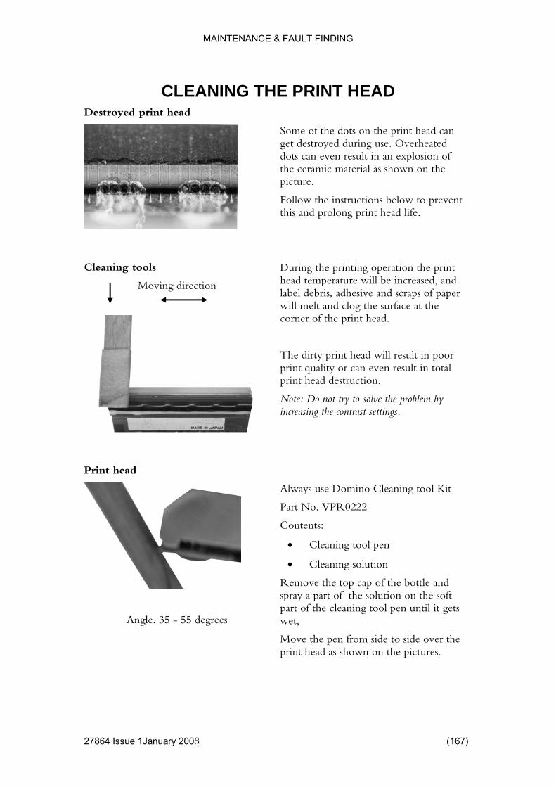
MAINTENANCE & FAULT FINDING
4 Issue 1January 2008 (167)
EAD Destroyed print head
CLEANING THE PRINT H
Some of the dots on the priget destroyed during use. Odots can even result in an ethe ceramic material as shown on the
nt head can verheated
xplosion of
Follow the instructions below to prevent this and prolong print head life.
Cleaning tools
Moving direction
picture.
tion the print e will be increased, and
label debris, adhesive and scraps of paper will melt and clog the surface at the
esult in poor n even result in total
print head destruction.
Note: Do not try to solve the problem by increasing the contrast settings.
Print head
During the printing operahead temperatur
corner of the print head.
The dirty print head will rprint quality or ca
Angle. 35 - 55 degrees
ino Cleaning tool Kit
bottle and spray a part of the solution on the soft part of the cleaning tool pen until it gets wet,
Move the pen from side to side over the print head as shown on the pictures.
Always use Dom
Part No. VPR0222
Contents:
• Cleaning tool pen
• Cleaning solution
Remove the top cap of the
2786

MAINTENANCE & FAULT FINDING
REPLACING THE PRINT HEAD
) 27864 Issue 1 January 2008
In this exam le a V200 is showp n Warning: Ensure printer is switched off and disconnected from the Mains supply. Remove the ribbon cassette from the printer by pulling the handle to release the cassette. Remove the unit and set aside. Take of the surrounding cover by first unscrewing the knurled screws and carefully lifting the cover off the chassis.
Disconnect the flat print head cable from the IDC connector by gently pulling it off squarely to avoid damaging the connector pins. Swivel the print head assembly to allow easy access to the 2 screws that hold the print head in place.
Using a 2.5 mm Allen key loosen the screws and remove the print head Caution: The print head will be hot if the printer was in use before this operation.
(168
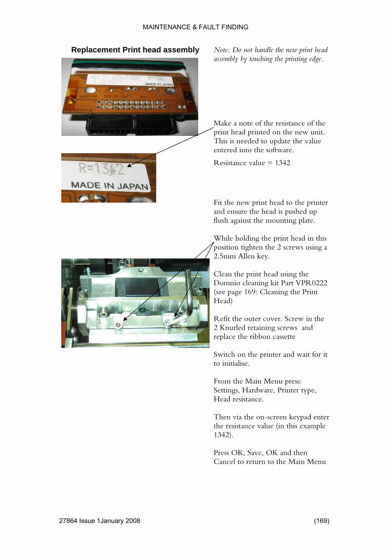
MAINTENANCE & FAULT FINDING
Replacement Print head assembly Note: Do not handle the new print head assembly by touching the printing edge.
Make a note of the resistance of the print head printe
d on the new unit. This is needed to update the value entered into the software.
Resistance value = 1342
Fit the new print head to the printer and ensure the head is pushed up flush against the mounting plate. While holding the print head in this position tighten the 2 screws using a 2.5mm Allen key. Clean the print head using the Domnio cleaning kit Part VPR0222 (see page 169: Cleaning the Print Head) Refit the outer cover. Screw in the 2 Knurled retaining screws and replace the ribbon cassette Switch on the printer and wait for it to initialise. From the Main Menu press: Settings, Hardware, Printer type, Head resistance. Then via the on-screen keypad enter the resistance value (in this example 1342). Press OK, Save, OK and then Cancel to return to the Main Menu
27864 Issue 1January 2008 (169)
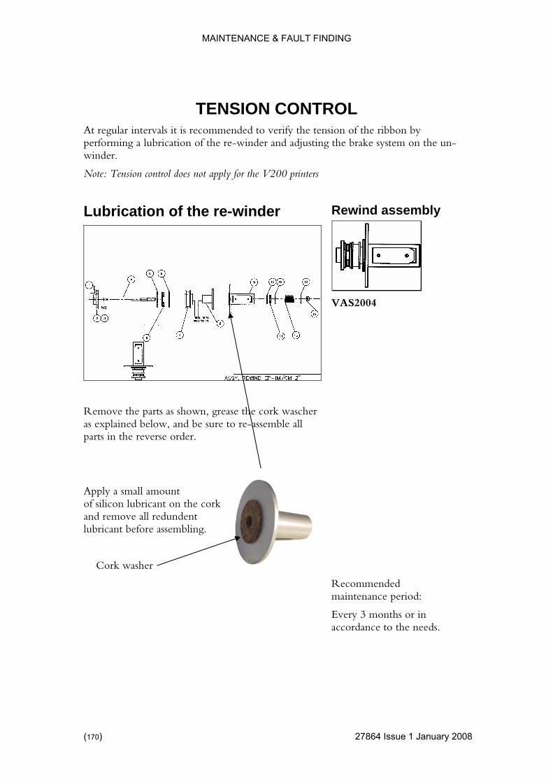
MAINTENANCE & FAULT FINDING
) 27864 Issue 1 January 2008
by ming a lubrication of the re-winder and adjusting the brake system on the un-
Note: Tension control does not apply for the V200 printers
Rewind assembly
TENSION CONTROL At regular intervals it is recommended to verify the tension of the ribbonperforwinder.
Lubrication of the re-winder
VAS2004
Remove the parts as shown, grease the cork wascher as explained below, and be sure to re-assemble all
order.
Apply a small amount ricant on the cork
and remove all redundent lubricant before assembling.
Cork washer
Recommended maintenance period:
Every 3 months or in accordance to the needs.
parts in the reverse
washer, of silicon lub
(170
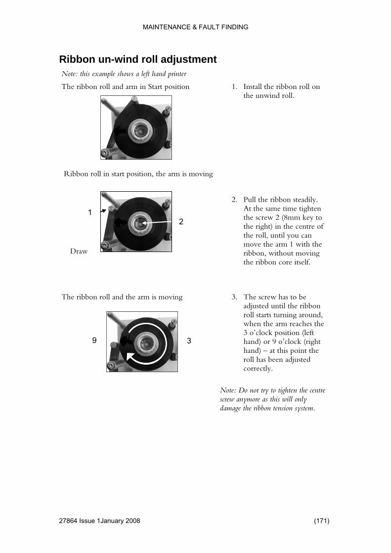
MAINTENANCE & FAULT FINDING
Ribbon un-wind roll adjustment Note: this example shows a left hand printer
4 Issue 1January 2008 (171)
1. Install tThe ribbon roll and arm in Start position he ribbon roll on the unwind roll.
Ribbon roll in start position, the arm is moving
1
Draw
2. Pull the ribbon steadily. At the same time tighten the screw 2 (8mm key to the right) in the centre of the roll, until you can move the arm 1 with the ribbon, without moving the ribbon core itself.
The ribbon roll and the arm is moving
3. The screw has to be adjusted until the ribbon roll starts turning around, when the arm reaches the 3 o’clock position (left hand) or 9 o’clock (right hand) – at this point the roll has been adjusted correctly.
Note: Do not try to tighten the centre screw anymore as this will only damage the ribbon tension system.
2
9 3
2786
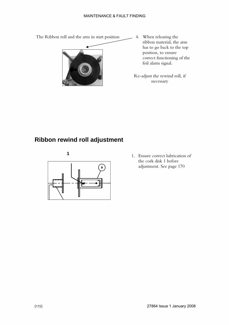
MAINTENANCE & FAULT FINDING
4. When releasinThe Ribbon roll and the arm in start position g the
ribbon material, the arm has to go back to the top position, to ensure correct functioning of the foil alarm signal.
Re-adjust the rewind roll, if necessary
wi d roll adjustme
Ribbon re n nt 1 1. Ensure correct lubrication of
the cork disk 1 before adjustment. See page 170
(172) 27864 Issue 1 January 2008
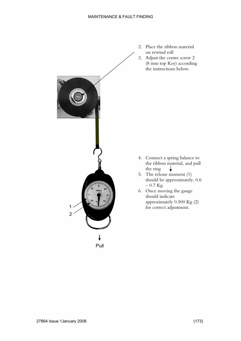
MAINTENANCE & FAULT FINDING
2. Place the ribbon material
on rewind roll
3. Adjust the centre screw 2 (8 mm top Key) according the instructions below.
4. Connect a spring balance to the ribbon material, and pull the ring
5. The release moment (1) should be approximately. 0.6 – 0.7 Kg.
6. Once moving the gauge should indicate approximately 0.500 Kg (2) for correct adjustment.
12
Pull
27864 Issue 1January 2008 (173)
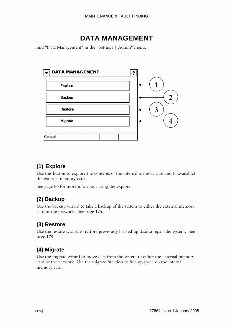
MAINTENANCE & FAULT FINDING
) 27864 Issue 1 January 2008
ENT Find "Data Management" in the "Settings | Admin" menu.
DATA MANAGEM
(1) Explore Use this button to explore the contents of the internal memory card and (if available) the external memory card.
See page 80 for more info about using the explorer
(2) Backup Use the backup wizard to take a backup of the system to either the external memory card or the network. See page 175.
(3) Restore Use the restore wizard to restore previously backed up data to repair the system. See page 179.
(4) Migrate Use the migrate wizard to move data from the system to either the external memory card or the network. Use the migrate function to free up space on the internal memory card.
3
1
4
2
(174

MAINTENANCE & FAULT FINDING
Backup
4 Issue 1January 2008 (175)
Backup wizard step one: Select destination.
al Area Network) emory card.
To use the LAN, a working network shortcut must be available.
st be inserted into the system before
(2) Path ath where the data is to be placed.
the external memory card).
Browses the media selected allowing easy selection of the correct path.
(4) Next Verifies the destination media and path, if accepted, the wizard takes the user one step further.
1 2
3
4
(1) Destination Use the drop down menu to select the destination media. LAN (Loccan be chosen or the external m
To use the external memory card, one muswitching on the V Series Controller.
Type in the p
A blank path indicates the root folder (only viable when using
(3) Browse
2786
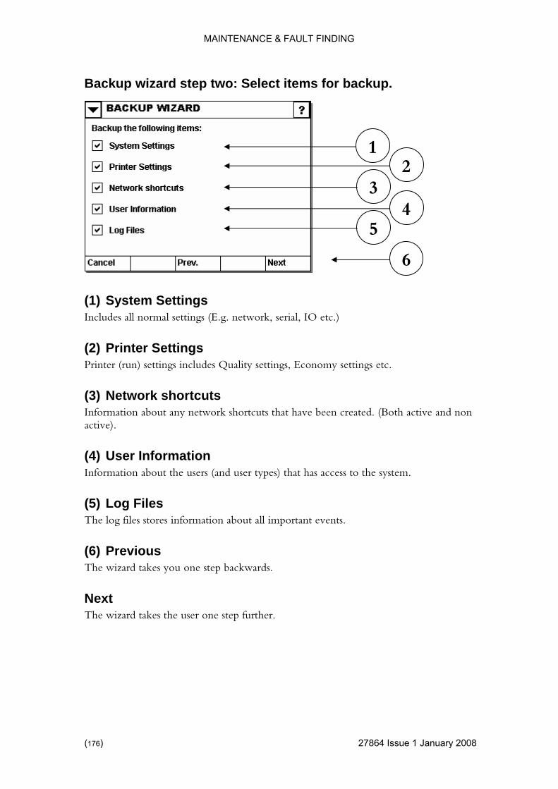
MAINTENANCE & FAULT FINDING
Backup wizard step two: Select items for backup.
) 27864 Issue 1 January 2008
gs
Information about the users (and user types) that has access to the system.
The log files stores information about all important events.
The wizard takes you one step backwards.
Next The wizard takes the user one step further.
1
(1) System SettinIncludes all normal settings (E.g. network, serial, IO etc.)
(2) Printer SettingsPrinter (run) settings includes Quality settings, Economy settings etc.
(3) Network shortcuts Information about any network shortcuts that have been created. (Both active and non active).
(4) User Information
(5) Log Files
(6) Previous
4 5
2 3
6
(176

MAINTENANCE & FAULT FINDING
Backup wizard step three: Select more items for backup.
4 Issue 1January 2008 (177)
rnal memory card.
d Designs r used.
Any dBase file the user has stored on the internal memory card.
Any user installed true type font.
The wizard takes you one step backwards.
Next The wizard takes the user one step further.
1
(1) Designs Label design stored on the inte
(2) RecalleOld designs that are no longe
(3) GraphicsGraphics used within the designs.
(4) Databases
(5) True Type Fonts
Previous
4 5
2 3
6
2786
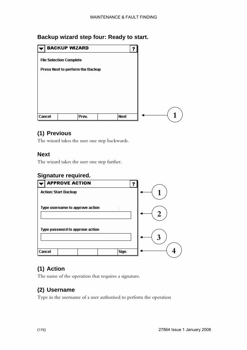
MAINTENANCE & FAULT FINDING
Backup wizard step four: Ready to start.
) 27864 Issue 1 January 2008
Previous ckwards.
The wizard takes the user one step further.
Signature required.
(1) Action The name of the operation that requires a signature.
(2) Username Type in the username of a user authorised to perform the operation
1
(1) The wizard takes the user one step ba
Next
3
1
2
4
(178
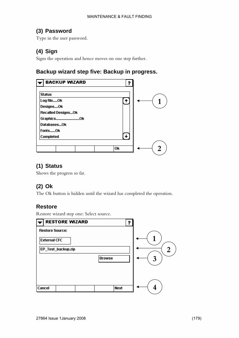
MAINTENANCE & FAULT FINDING
(3) Password
4 Issue 1January 2008 (179)
Type in the user password.
Signs the operation and hence moves on one step further.
Backup wizard step five: Backup in progress.
atus
The Ok button is hidden until the wizard has completed the operation.
Restore Restore wizard step one: Select source.
(4) Sign
(1) StShows the progress so far.
(2) Ok
1
3
4
2
2
1
2786
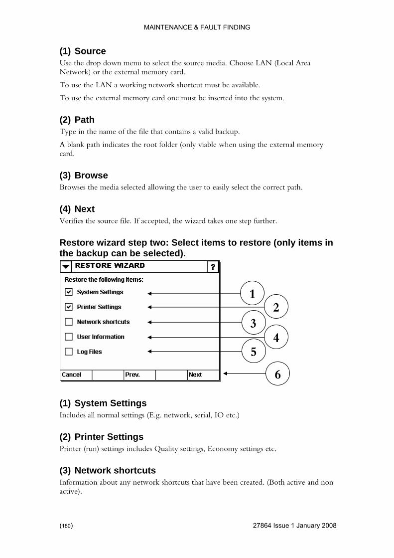
MAINTENANCE & FAULT FINDING
(1) Sourc
) 27864 Issue 1 January 2008
the source media. Choose LAN (Local Area
.
To use the external memory card one must be inserted into the system.
A blank path indicates the root folder (only viable when using the external memory
(3) Browse he media selected allowing the user to easily select the correct path.
Restore wizard step two: Select items to restore (only items in the backup can be selected).
(1) System Settings (E.g. network, serial, IO etc.)
Printer (run) settings includes Quality settings, Economy settings etc.
(3) Network shortcuts Information about any network shortcuts that have been created. (Both active and non active).
e Use the drop down menu to selectNetwork) or the external memory card.
To use the LAN a working network shortcut must be available
(2) Path Type in the name of the file that contains a valid backup.
card.
Browses t
(4) Next Verifies the source file. If accepted, the wizard takes one step further.
1
Includes all normal settings
(2) Printer Settings
4
2 3
5
6
(180
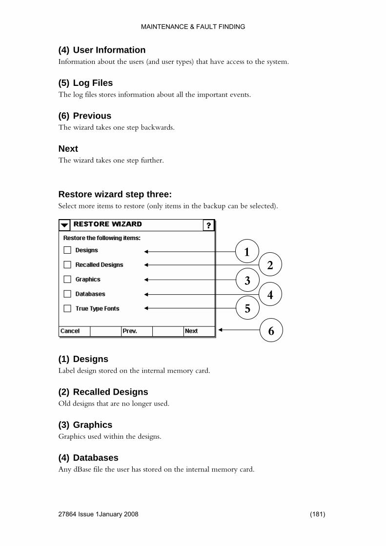
MAINTENANCE & FAULT FINDING
(4) User Information
4 Issue 1January 2008 (181)
Information about the users (and user types) that have access to the system.
The log files stores information about all the important events.
wizard takes one step backwards.
Next The wizard takes one step further.
Restore wizard step three: Select more items to restore (only items in the backup can be selected).
emory card.
are no longer used.
(3) Graphics Graphics used within the designs.
(4) Databases Any dBase file the user has stored on the internal memory card.
(5) Log Files
(6) Previous The
1
(1) Designs Label design stored on the internal m
(2) Recalled Designs Old designs that
4 5
2 3
6
2786
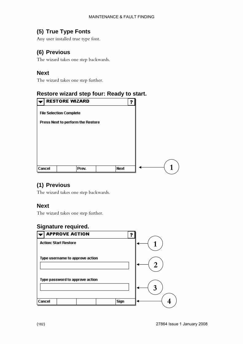
MAINTENANCE & FAULT FINDING
) 27864 Issue 1 January 2008
Any user installed true type font.
The wizard takes one step backwards.
Restore wizard step four: Ready to start.
Previous
Next The wizard takes one step further.
Signature required.
(5) True Type Fonts
(6) Previous
Next The wizard takes one step further.
(1) The wizard takes one step backwards.
1
3
1
2
4
(182
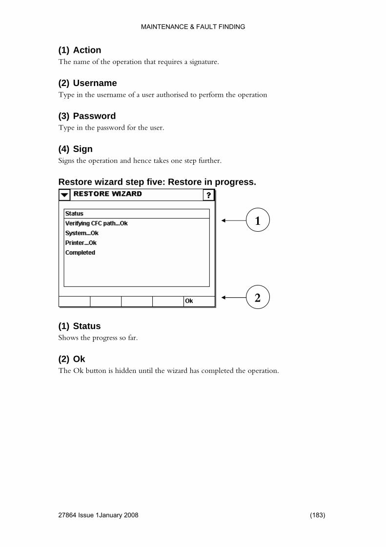
MAINTENANCE & FAULT FINDING
(1) Action
4 Issue 1January 2008 (183)
The name of the operation that requires a signature.
Type in the username of a user authorised to perform the operation
he password for the user.
(4) Sign
Restore wizard step five: Restore in progress.
Shows the progress so far.
(2) Ok The Ok button is hidden until the wizard has completed the operation.
(2) Username
(3) Password Type in t
Signs the operation and hence takes one step further.
(1) Status
2
1
2786
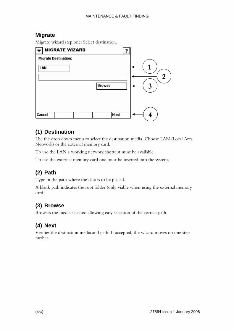
MAINTENANCE & FAULT FINDING
Migrate
) 27864 Issue 1 January 2008
Migrate wizard step one: Select destination.
ose LAN (Local Area
e LAN a working network shortcut must be available.
st be inserted into the system.
Path ath where the data is to be placed.
the external memory card.
es the media selected allowing easy selection of the correct path.
(4) Next Verifies the destination media and path. If accepted, the wizard moves on one step further.
1
(1) Destination Use the drop down menu to select the destination media. ChoNetwork) or the external memory card.
To use th
To use the external memory card one mu
(2)Type in the p
A blank path indicates the root folder (only viable when using
(3) Browse Brows
3 2
4
(184
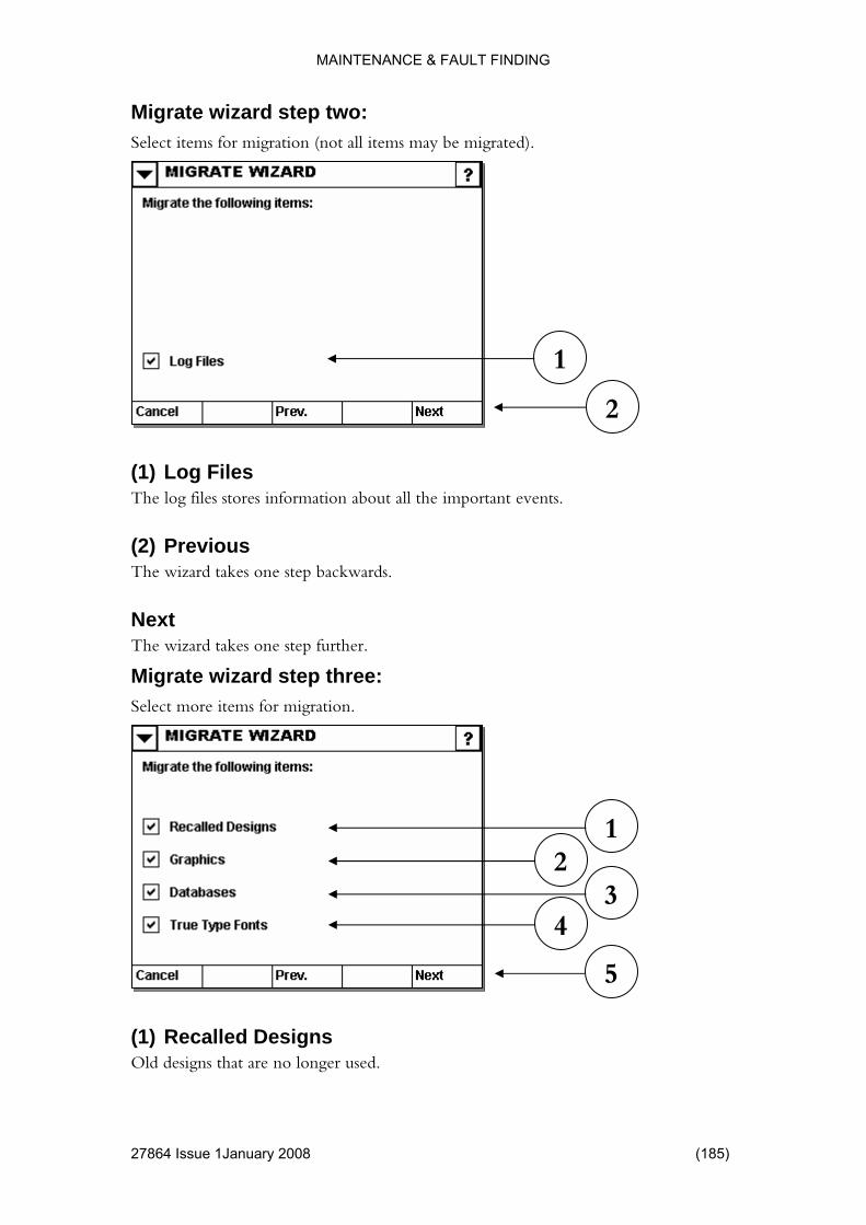
MAINTENANCE & FAULT FINDING
1January 2008 (185)
o: Select items for migration (not all items may be migrated).
s bout all the important events.
Previous kwards.
The wizard takes one step further.
Migrate wizard step three: Select more items for migration.
(1) Recalled Designs Old designs that are no longer used.
Migrate wizard step tw
1
2
(1) Log FileThe log files stores information a
(2) The wizard takes one step bac
Next
3 4
1 2
5
27864 Issue

MAINTENANCE & FAULT FINDING
(2) Graphics
) 27864 Issue 1 January 2008
Graphics used within the designs.
Any dBase file the user has stored on the internal memory card.
led true type font.
(5) Previous wizard takes one step backwards.
Next her.
Migrate wizard step four: Ready to start.
The wizard takes one step backwards.
Next The wizard takes one step further.
(3) Databases
(4) True Type Fonts Any user instal
The
The wizard takes one step furt
1
(1) Previous
(186

MAINTENANCE & FAULT FINDING
4 Issue 1January 2008 (187)
d.
operation that requires a signature.
e r authorized to perform the operation
sword
Migrate wizard step five: Migration in progress.
Signature require
1
2
3
(1) Action The name of the
(2) UsernamType in the username of a use
(3) PasType in the password for the user.
(4) Sign Signing the operation takes the user one step further.
4
2
1
2786

MAINTENANCE & FAULT FINDING
(1) Status
) 27864 Issue 1 January 2008
Shows the progress so far.
til the wizard has completed the operation.
step six: Migration verification.
on the screen.
Shut down the system to remove the memory card.
Migrate wizard step seven: Migration completion.
(1) Cancel Indicates to the system that the migration has failed and all data must be retained.
(2) Ok The Ok button is hidden un
Migrate wizard
(1) Migrate Verification Follow instructions
1
1
(188

MAINTENANCE & FAULT FINDING
Ok Indicates to the system that the migrated data is safely stored on permanent storage and therefore may be purged from the system.
27864 Issue 1January 2008 (189)
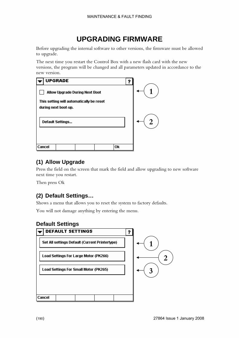
MAINTENANCE & FAULT FINDING
UPGRADING FIRMW
) 27864 Issue 1 January 2008
grading the internal software to other versions, the firmware must be allowed
ew ll parameters updated in accordance to the
new version.
Upgrade Press the field on the screen that mark the field and allow upgrading to new software
ttings… defaults.
You will not damage anything by entering the menu.
Default Settings
ARE Before upto upgrade.
The next time you restart the Control Box with a new flash card with the nversions, the program will be changed and a
(1) Allow
next time you restart.
Then press Ok
(2) Default SeShows a menu that allows you to reset the system to factory
2
1
3
1
2
(190

MAINTENANCE & FAULT FINDING
(1) Set All Settings Default
set just a single run setting (which may sometimes be a better solution). Please see page 153.
66.
odified the printer.
se the stepper motor PK265.
This button must be used if the firmware has been updated and the printer is equipped with the stepper motor PK265.
Resets ALL run settings to factory defaults.
This is an alternative to re
(2) Load Settings for Large Motor Enables the controller to use the stepper motor PK2
Use this button if you have physically m
(3) Load Settings for Small Motor Enables the controller to u
27864 Issue 1January 2008 (191)

MAINTENANCE & FAULT FINDING
Data Management
) 27864 Issue 1 January 2008
n to explore the contents of the internal memory card and (if available) lorer
(2) Backup p wizard to take a backup of the system to either the external memory
re stem. See
(4) Migrate Use the migrate wizard to move data from the system to either the external memory card or the network. Use the migrate function to free up space on the internal memory card.
(1) Explore Use this buttothe external memory card. See page 80 for more info about using the exp
Use the backucard or the network. See page 175.
(3) RestoUse the restore wizard to restore previously backed up data to repair the sypage 179.
3
1
4
2
(192
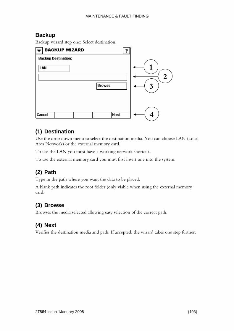
MAINTENANCE & FAULT FINDING
Backup
4 Issue 1January 2008 (193)
Backup wizard step one: Select destination.
e LAN you must have a working network shortcut.
insert one into the system.
Path ath where you want the data to be placed.
the external memory card.
Browses the media selected allowing easy selection of the correct path.
(4) Next Verifies the destination media and path. If accepted, the wizard takes one step further.
1 2
3
4
(1) Destination Use the drop down menu to select the destination media. You can choose LAN (Local Area Network) or the external memory card.
To use th
To use the external memory card you must first
(2)Type in the p
A blank path indicates the root folder (only viable when using
(3) Browse
2786
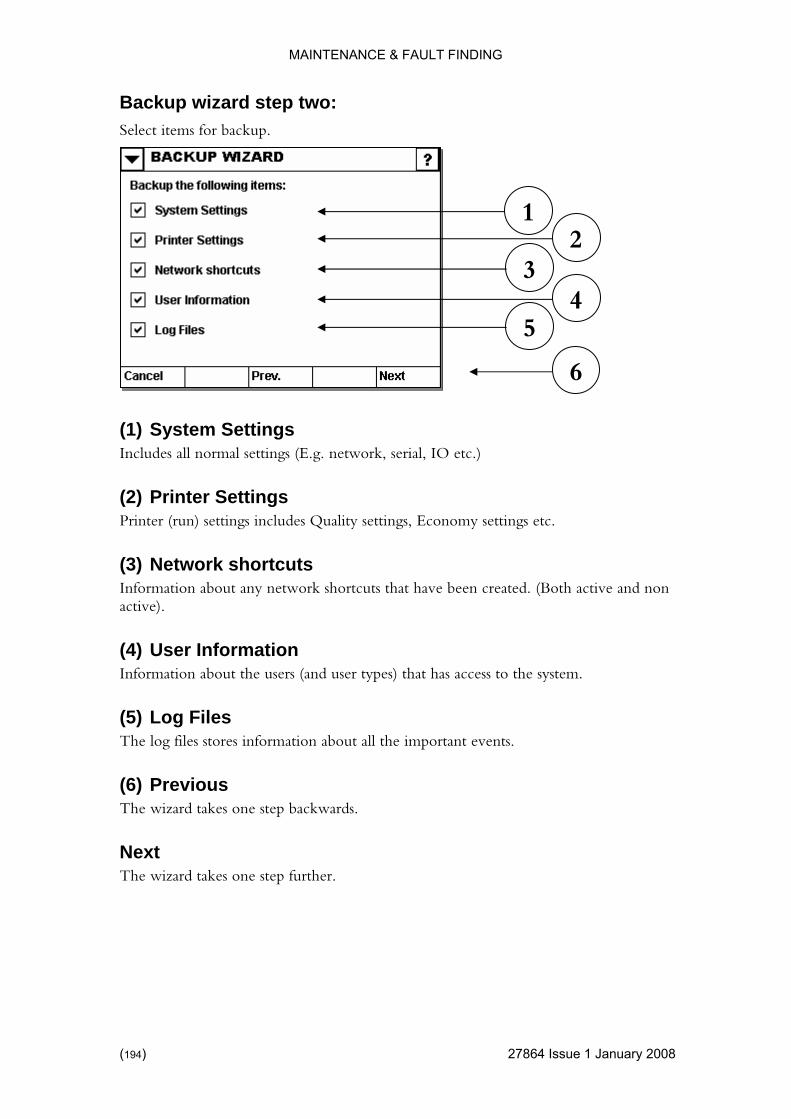
MAINTENANCE & FAULT FINDING
27864 Issue 1 January 2008
o: Select items for backup.
gs
cuts
Information about the users (and user types) that has access to the system.
The log files stores information about all the important events.
The wizard takes one step backwards.
Next The wizard takes one step further.
Backup wizard step tw
1
(1) System SettinIncludes all normal settings (E.g. network, serial, IO etc.)
(2) Printer SettingsPrinter (run) settings includes Quality settings, Economy settings etc.
(3) Network shortInformation about any network shortcuts that have been created. (Both active and non active).
(4) User Information
(5) Log Files
(6) Previous
4 5
2 3
6
(194)
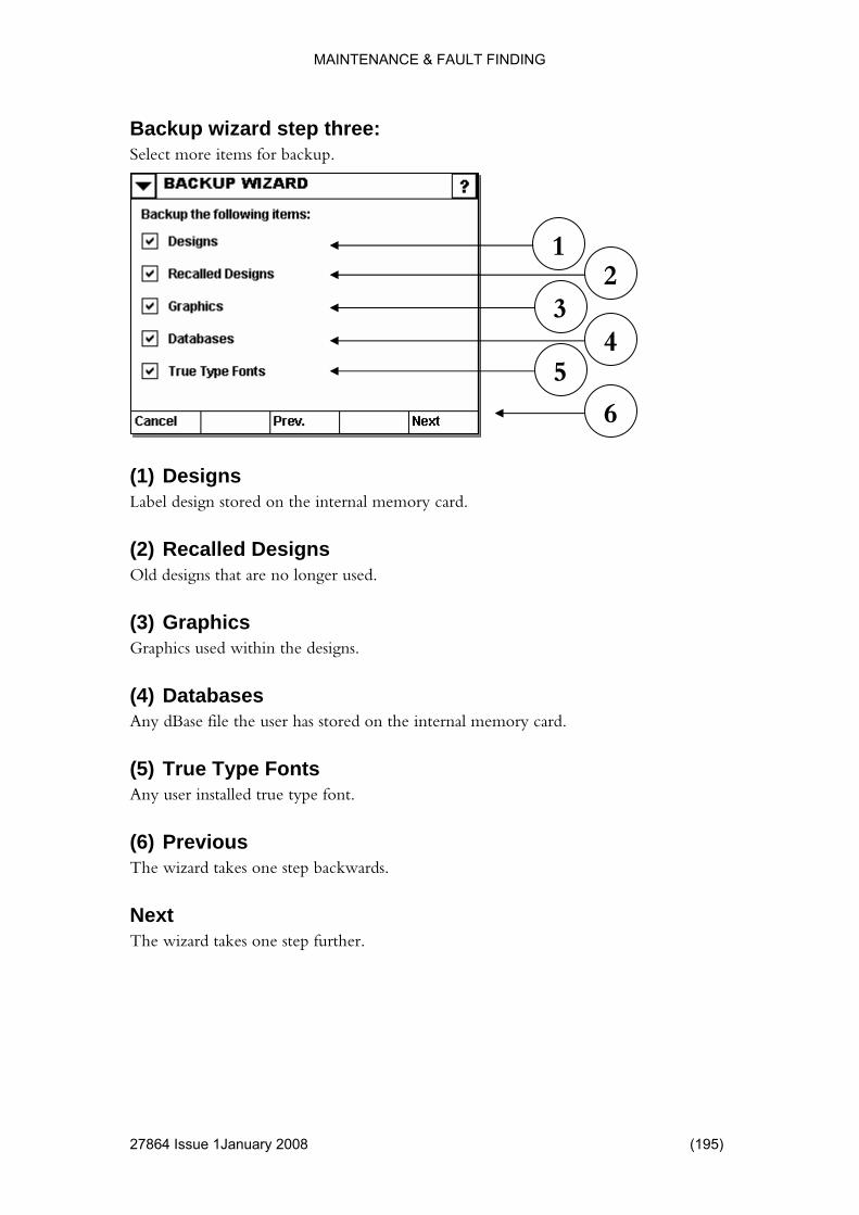
MAINTENANCE & FAULT FINDING
4 Issue 1January 2008 (195)
ree: Select more items for backup.
rnal memory card.
d Designs r used.
Any dBase file the user has stored on the internal memory card.
Any user installed true type font.
The wizard takes one step backwards.
Next The wizard takes one step further.
Backup wizard step th
1
(1) Designs Label design stored on the inte
(2) RecalleOld designs that are no longe
(3) GraphicsGraphics used within the designs.
(4) Databases
(5) True Type Fonts
(6) Previous
4 5
2 3
6
2786

MAINTENANCE & FAULT FINDING
) 27864 Issue 1 January 2008
ur: Ready to start.
Previous kwards.
The wizard takes one step further.
Signature required.
(1) Action The name of the operation that requires a signature.
(2) Username Type in the username of a user authorised to perform the operation
Backup wizard step fo
1
(1) The wizard takes one step bac
Next
3
1
2
4
(196

MAINTENANCE & FAULT FINDING
(3) Password
4 Issue 1January 2008 (197)
Type in the password for the user.
Signs the operation and hence takes you one step further.
rd step five: Backup in progress.
atus
(2) Ok The Ok button is hidden until the wizard has completed the operation.
(4) Sign
Backup wiza
(1) StShows the progress so far.
2
1
2786
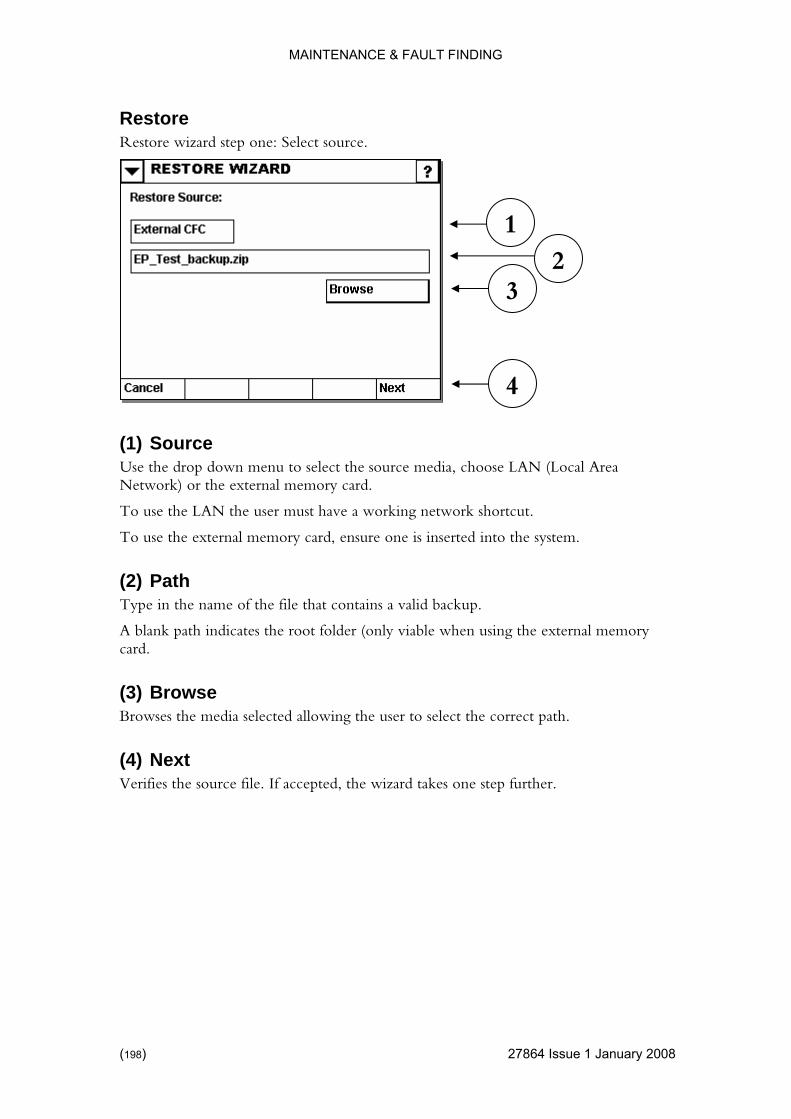
MAINTENANCE & FAULT FINDING
Restore
) 27864 Issue 1 January 2008
Restore wizard step one: Select source.
e LAN the user must have a working network shortcut.
serted into the system.
Path ame of the file that contains a valid backup.
the external memory card.
Browses the media selected allowing the user to select the correct path.
(4) Next Verifies the source file. If accepted, the wizard takes one step further.
1
(1) Source Use the drop down menu to select the source media, choose LAN (Local Area Network) or the external memory card.
To use th
To use the external memory card, ensure one is in
(2)Type in the n
A blank path indicates the root folder (only viable when using
(3) Browse
3 2
4
(198

MAINTENANCE & FAULT FINDING
Restore wizard step two:
4 Issue 1January 2008 (199)
Select items to restore (only items in the backup can be selected).
gs
cuts . (Both active and non
Information about the users (and user types) that has access to the system.
stores information about all the important events.
The wizard takes one step backwards.
Next The wizard takes one step further.
1
(1) System SettinIncludes all normal settings (E.g. network, serial, IO etc.)
(2) Printer SettingsPrinter (run) settings includes Quality settings, Economy settings etc.
(3) Network shortInformation about any network shortcuts that have been createdactive).
(4) User Information
(5) Log Files The log files
(6) Previous
4
2 3
5
6
2786

MAINTENANCE & FAULT FINDING
Restore wizard step three:
) 27864 Issue 1 January 2008
Select more items to restore (only items in the backup can be selected).
rnal memory card.
d Designs r used.
Any dBase file the user has stored on the internal memory card.
Any user installed true type font.
The wizard takes one step backwards.
Next The wizard takes one step further.
1
(1) Designs Label design stored on the inte
(2) RecalleOld designs that are no longe
(3) GraphicsGraphics used within the designs.
(4) Databases
(5) True Type Fonts
(6) Previous
4 5
2 3
6
(200
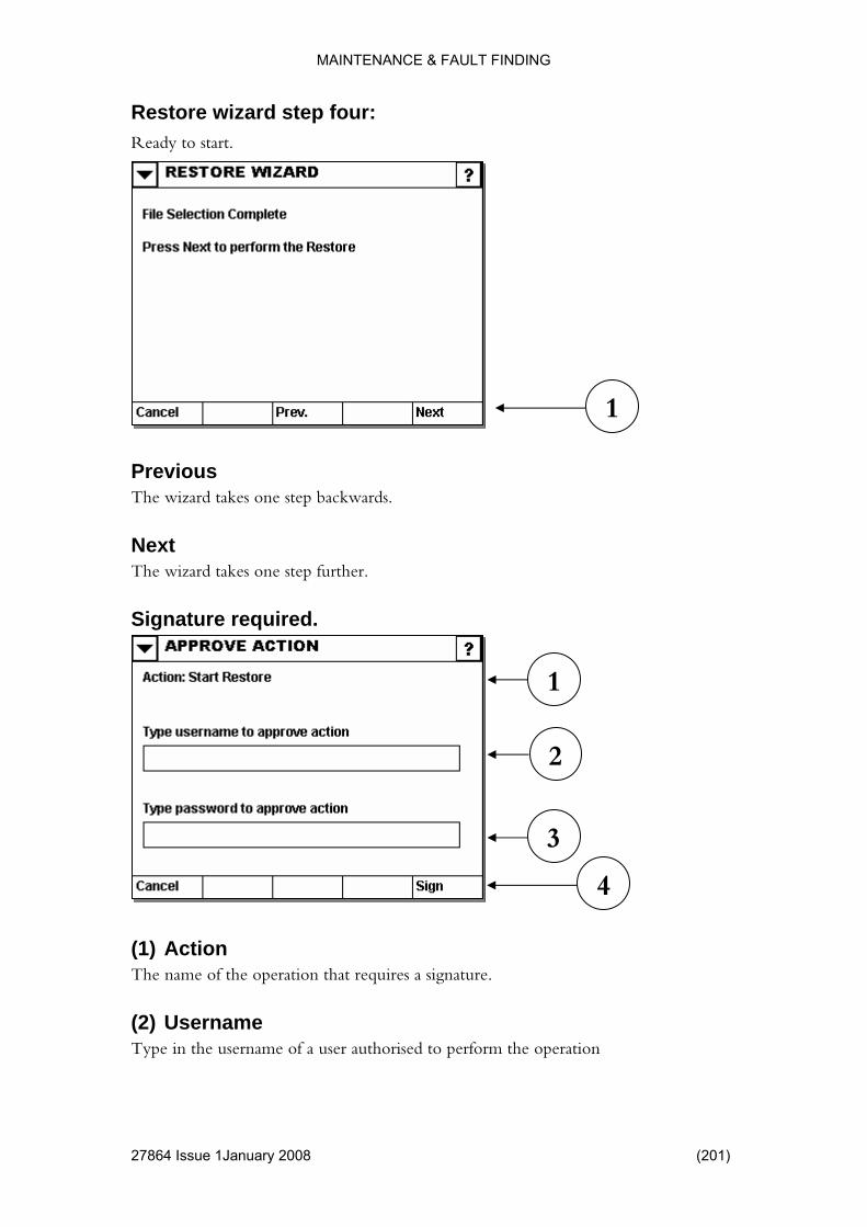
MAINTENANCE & FAULT FINDING
1January 2008 (201)
ur: Ready to start.
vious kwards.
The wizard takes one step further.
Signature required.
(1) Action The name of the operation that requires a signature.
(2) Username Type in the username of a user authorised to perform the operation
Restore wizard step fo
1
PreThe wizard takes one step bac
Next
3
1
2
4
27864 Issue
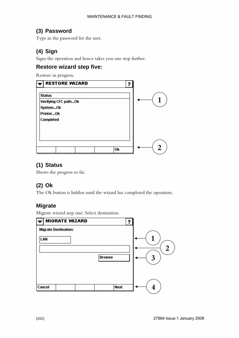
MAINTENANCE & FAULT FINDING
(3) Password
) 27864 Issue 1 January 2008
Type in the password for the user.
takes you one step further.
rd step five: Restore in progress.
atus
The Ok button is hidden until the wizard has completed the operation.
Migrate Migrate wizard step one: Select destination.
(4) Sign Signs the operation and hence
Restore wiza
(1) StShows the progress so far.
(2) Ok
1
3 2
4
2
1
(202
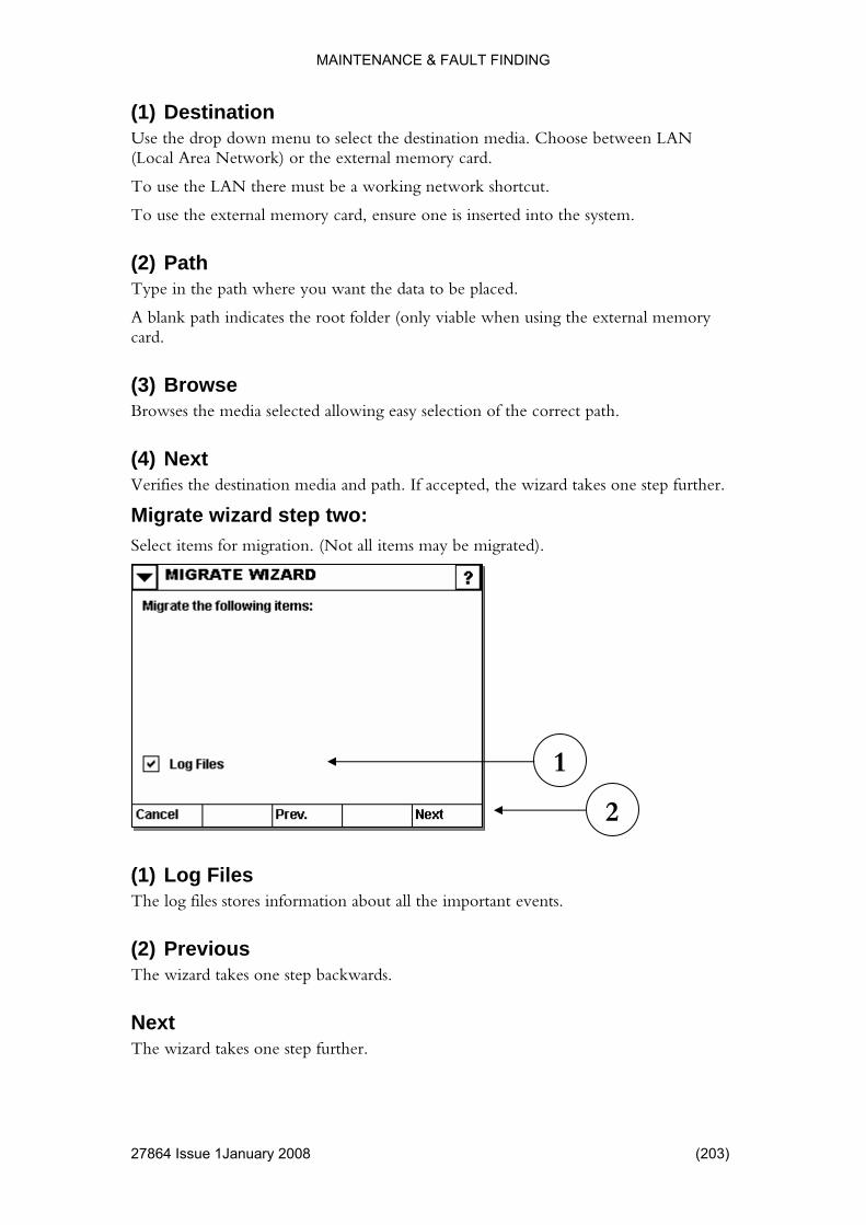
MAINTENANCE & FAULT FINDING
(1) Destinatio
4 Issue 1January 2008 (203)
ation media. Choose between LAN
To use the external memory card, ensure one is inserted into the system.
A blank path indicates the root folder (only viable when using the external memory
(3) Browse he media selected allowing easy selection of the correct path.
the wizard takes one step further.
Migrate wizard step two: Select items for migration. (Not all items may be migrated).
log files stores information about all the important events.
(2) Previous The wizard takes one step backwards.
Next The wizard takes one step further.
n Use the drop down menu to select the destin(Local Area Network) or the external memory card.
To use the LAN there must be a working network shortcut.
(2) Path Type in the path where you want the data to be placed.
card.
Browses t
(4) Next Verifies the destination media and path. If accepted,
1
2
(1) Log Files The
2786

MAINTENANCE & FAULT FINDING
27864 Issue 1 January 2008
ee: Select more items for migration.
d Designs r used.
tored on the internal memory card.
Any user installed true type font.
The wizard takes one step backwards.
Next The wizard takes one step further.
Migrate wizard step thr
(1) RecalleOld designs that are no longe
(2) GraphicsGraphics used within the designs.
(3) Databases Any dBase file the user has s
(4) True Type Fonts
(5) Previous
3 4
1 2
5
(204)
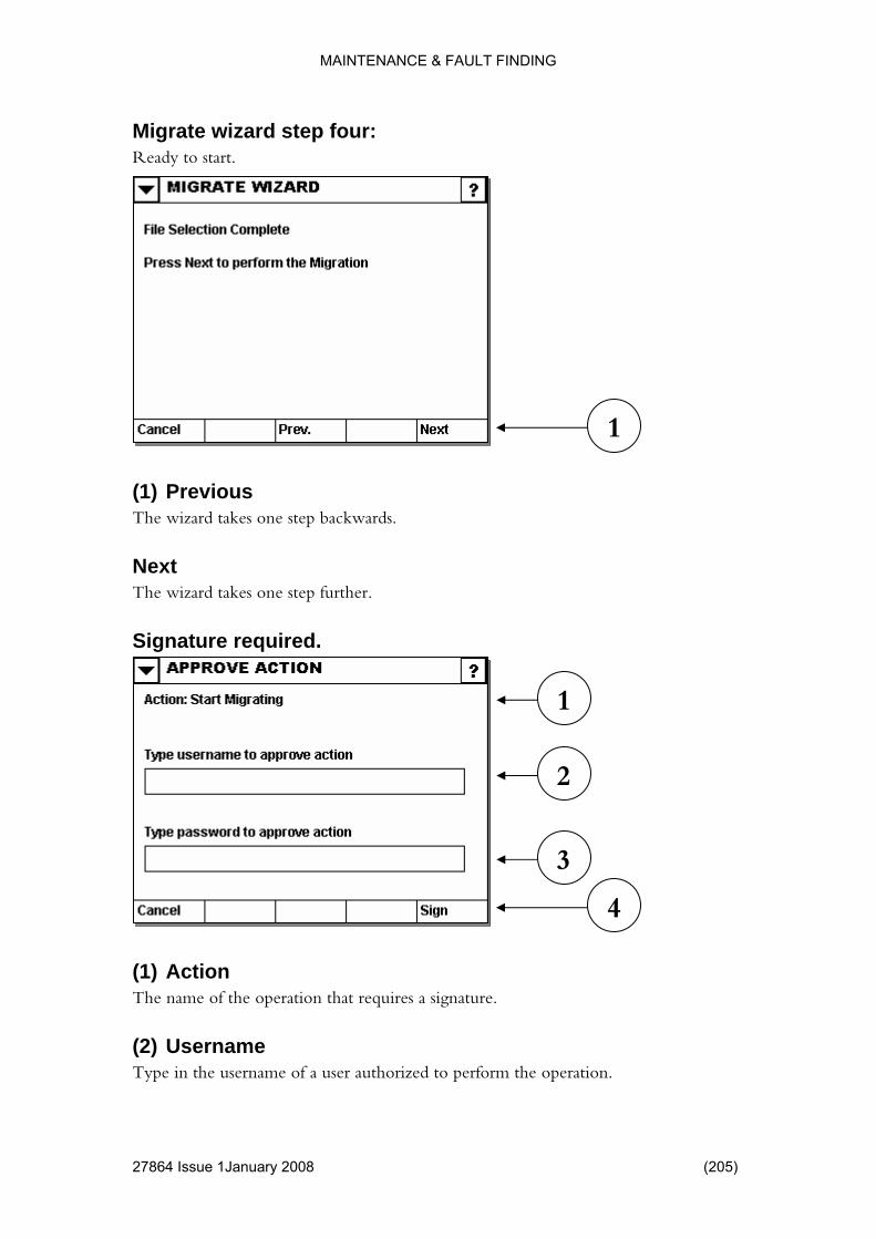
MAINTENANCE & FAULT FINDING
4 Issue 1January 2008 (205)
ur: Ready to start.
Previous kwards.
The wizard takes one step further.
Signature required.
(1) Action The name of the operation that requires a signature.
(2) Username Type in the username of a user authorized to perform the operation.
Migrate wizard step fo
(1) The wizard takes one step bac
Next
3
2
1
4
1
2786
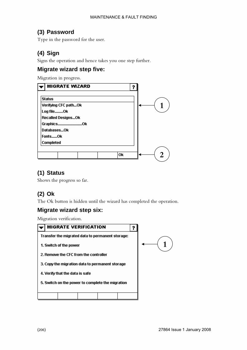
MAINTENANCE & FAULT FINDING
(3) Password
) 27864 Issue 1 January 2008
Type in the password for the user.
takes you one step further.
d step five: Migration in progress.
atus
The Ok button is hidden until the wizard has completed the operation.
Migrate wizard step six: Migration verification.
(4) Sign Signs the operation and hence
Migrate wizar
(1) StShows the progress so far.
(2) Ok
1
2
1
(206

MAINTENANCE & FAULT FINDING
4 Issue 1January 2008 (207)
n
system to remove the memory card.
step seven: Migration completion.
) Cancel ined.
Ok Indicates to the system that the migrated data is safely stored on permanent storage and therefore may be purged from the system.
(1) Migrate VerificatioFollow instructions on the screen.
You are forced to shut down the
Migrate wizard
1
(1Indicates to the system that the migration has failed and all data must be reta
2786
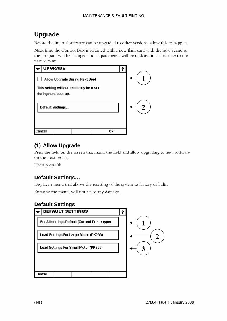
MAINTENANCE & FAULT FINDING
Upgrade
) 27864 Issue 1 January 2008
versions, m will be changed and all parameters will be updated in accordance to the
new version.
Upgrade Press the field on the screen that marks the field and allow upgrading to new software
at allows the resetting of the system to factory defaults.
Entering the menu, will not cause any damage.
Default Settings
Before the internal software can be upgraded to other versions, allow this to happen.
Next time the Control Box is restarted with a new flash card with the newthe progra
(1) Allow
on the next restart.
Then press Ok
Default Settings… Displays a menu th
3
1
2
2
1
(208

MAINTENANCE & FAULT FINDING
(1) Set All Settings Default
(which may sometimes be a better solution). Please see page 153.
r has been physically modified.
to use the stepper motor PK265.
Use this button if the firmware has been updated AND the printer is equipped with the stepper motor PK265.
Resets ALL run settings to factory defaults.
You have the alternative to reset just a single run setting
(2) Load Settings for Large Motor Enables the controller to use the stepper motor PK266.
This button is only required if the printe
(3) Load Settings for Small Motor Enables the controller
27864 Issue 1January 2008 (209)

MAINTENANCE & FAULT FINDING
FAULT FINDING
rinter unit.
or Test” menu can be reached from the “Main” menu by:
or Test.
s between “On”
Reflective sensors can be activated by a blank piece of metal.
Fork sensors can be activated by inserting a thin piece of paper between the transmitter and receiver.
Sensor test Sometimes it is required to test the sensors of the p
To do so, go to the “Sensor Test” menu of the controller.
The “Sens
(1) Settings
(2) Hardware
(3) Diagnostics
(4) Sens
Activate the appropriate sensor and observe that the display switcheand “Off”.
Use the images on the next few pages to locate the sensors. Sensors may vary dependent on the actual printer model.
(210) 27864 Issue 1 January 2008
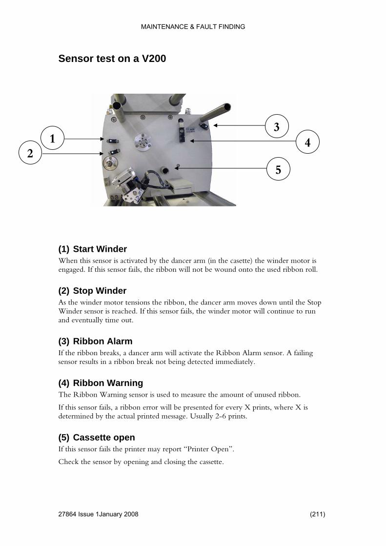
MAINTENANCE & FAULT FINDING
Sensor test on a V200
4 Issue 1January 2008 (211)
3 4 1
2 5
(1) Start Winder activated by the dancer arm (in the casette) the winder motor is
bon roll.
(2) Stop Winder tensions the ribbon, the dancer arm moves down until the Stop
inue to run
sor. A failing
ning e amount of unused ribbon.
ted for every X prints, where X is determined by the actual printed message. Usually 2-6 prints.
(5) Cassette open If this sensor fails the printer may report “Printer Open”.
Check the sensor by opening and closing the cassette.
When this sensor isengaged. If this sensor fails, the ribbon will not be wound onto the used rib
As the winder motorWinder sensor is reached. If this sensor fails, the winder motor will contand eventually time out.
(3) Ribbon AlarmIf the ribbon breaks, a dancer arm will activate the Ribbon Alarm sensensor results in a ribbon break not being detected immediately.
(4) Ribbon WarThe Ribbon Warning sensor is used to measure th
If this sensor fails, a ribbon error will be presen
2786
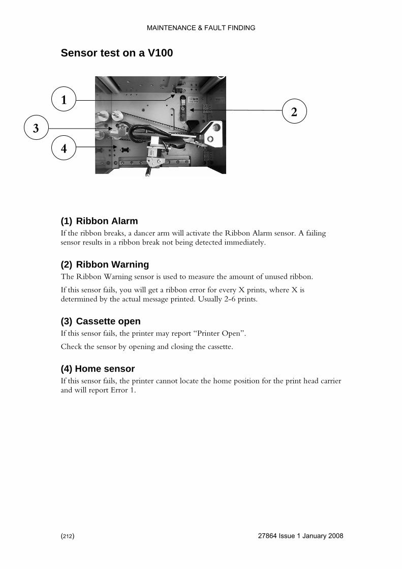
MAINTENANCE & FAULT FINDING
) 27864 Issue 1 January 2008
00
Sensor test on a V1
1 2
3
4
(1) Ribbon Alarm ancer arm will activate the Ribbon Alarm sensor. A failing
The Ribbon Warning sensor is used to measure the amount of unused ribbon.
will get a ribbon error for every X prints, where X is 2-6 prints.
pen
opening and closing the cassette.
(4) Home sensor If this sensor fails, the printer cannot locate the home position for the print head carrier and will report Error 1.
If the ribbon breaks, a dsensor results in a ribbon break not being detected immediately.
(2) Ribbon Warning
If this sensor fails, youdetermined by the actual message printed. Usually
(3) Cassette oIf this sensor fails, the printer may report “Printer Open”.
Check the sensor by
(212

MAINTENANCE & FAULT FINDING
Sensor test on a V400
4 Issue 1January 2008 (213)
1
1
(1) Magnetic sensors Detect if the cover is removed. The magnetic sensors are connected in series so it is difficult to verify which one is faulty.
2786

MAINTENANCE & FAULT FINDING
Print head carrier Printer front (left side)
(1) Ribbon Alarm ancer arm will activate the Ribbon Alarm sensor. A failing
The Ribbon Warning sensor is used to measure the amount of unused ribbon.
X is
(3) Home sensor If this sensor fails, the printer cannot locate the home position for the print head carrier and reports Error 1.
3 1 2
If the ribbon breaks, a dsensor results in a ribbon break not being detected immediately.
(2) Ribbon Warning
If this sensor fails, a ribbon error will be presented for every X prints, where determined by the actual message printed. Usually 2-6 prints.
(214) 27864 Issue 1 January 2008
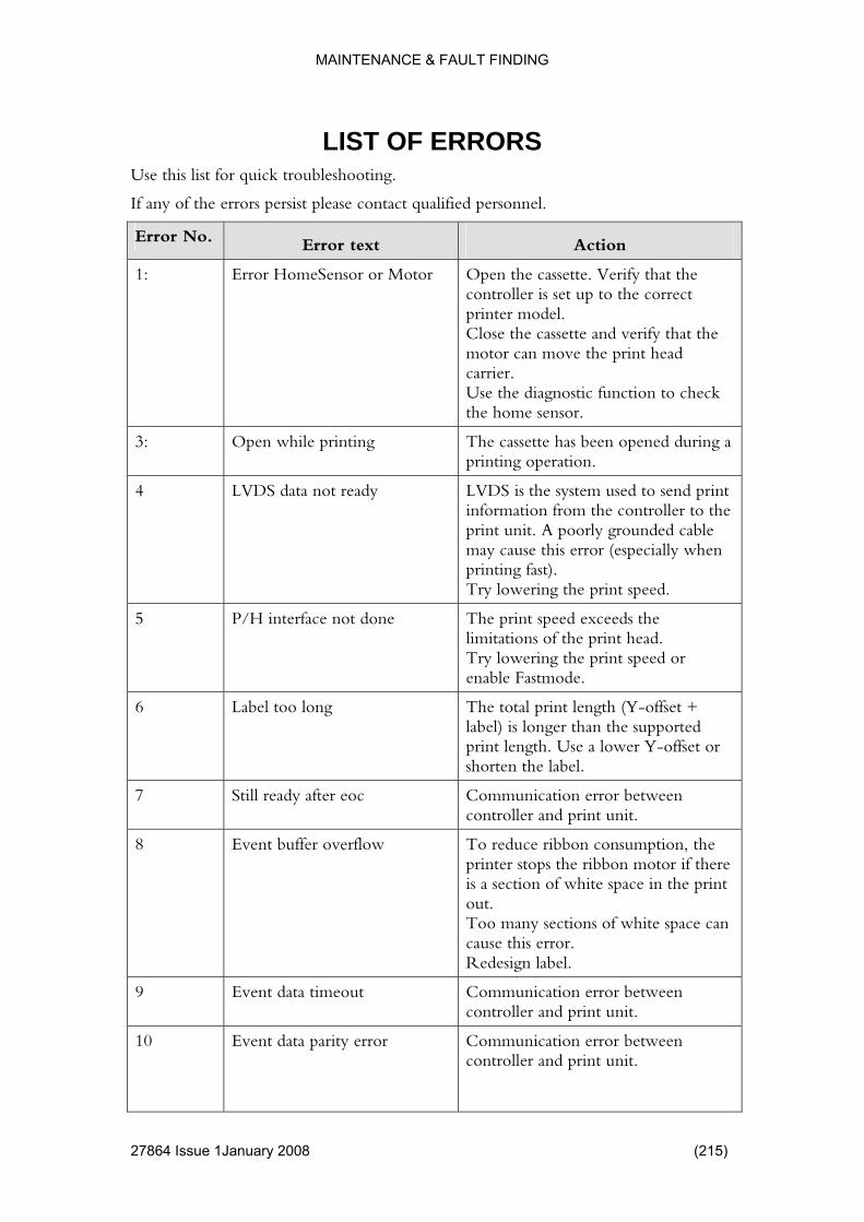
MAINTENANCE & FAULT FINDING
LIST OF ERRORS
he errors persist please contact qualified personnel.
Use this list for quick troubleshooting.
If any of t
Error No. Error text Action
1: Error HomeSensor or Mo the cassette. Verify that the correct
Close the cassette and verify that the head
to check sensor.
tor Open controller is set up to the printer model.
motor can move the printcarrier. Use the diagnostic functionthe home
3: ting ed during a Open while prin The cassette has been openprinting operation.
4 LVDS data not ready send print ation from the controller to the
grounded cable r (especially when
t speed.
LVDS is the system used toinformprint unit. A poorlymay cause this erroprinting fast). Try lowering the prin
5 ace not done s the ead.
stmode.
P/H interf The print speed exceedlimitations of the print hTry lowering the print speed or enable Fa
6
(Y-offset + han the supported
Y-offset or
Label too long The total print lengthlabel) is longer tprint length. Use a lower shorten the label.
7 Still ready after eoc Communication error between controller and print unit.
8 Event buffer overflow ce ribbon consumption, the
pace in the print
white space can
Redesign label.
To reduprinter stops the ribbon motor if there is a section of white sout. Too many sections ofcause this error.
9 Event data timeout Communication error between controller and print unit.
10
Event data parity error Communication error between controller and print unit.
27864 Issue 1January 2008 (215)
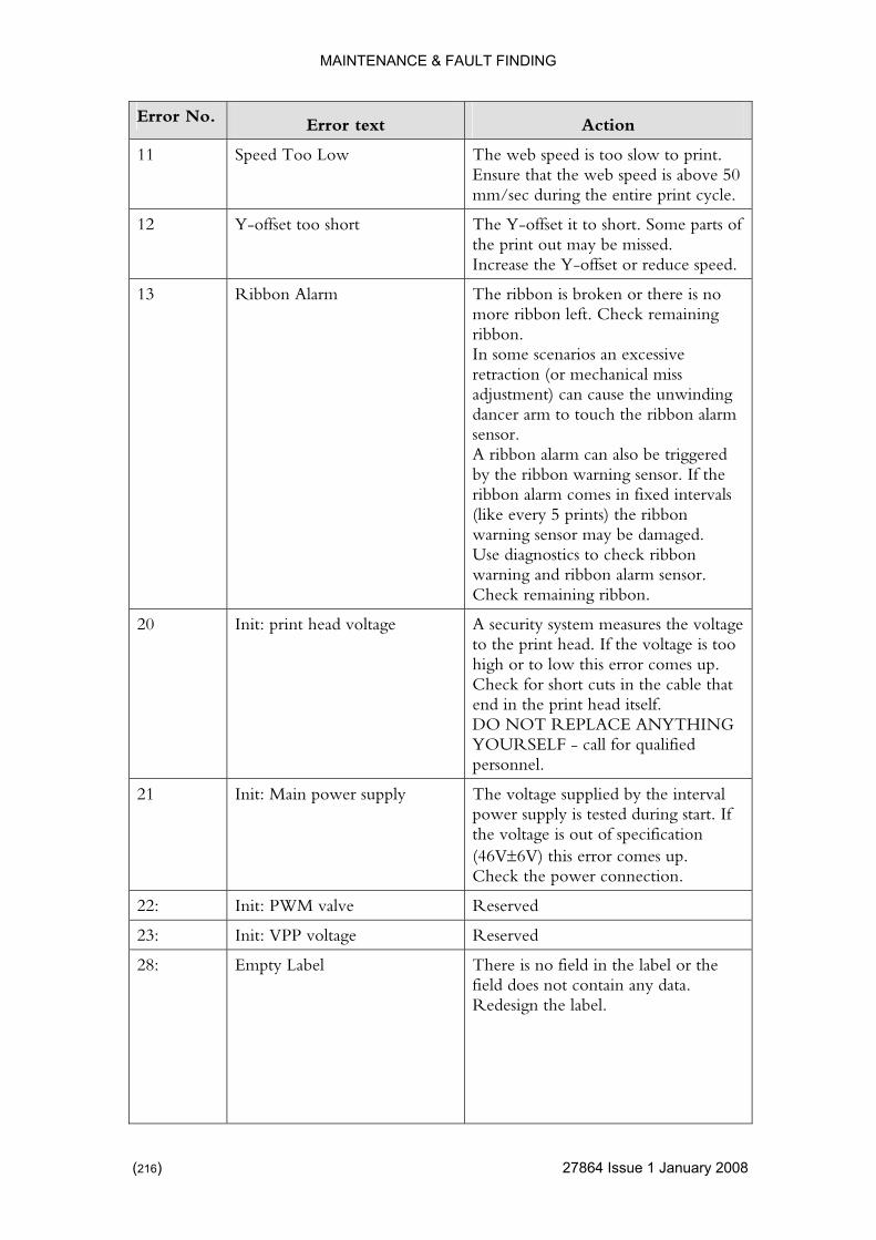
MAINTENANCE & FAULT FINDING
Error No. Error text Action
11 Speed Too Low to print. is above 50 rint cycle.
The web speed is too slow Ensure that the web speed mm/sec during the entire p
12 Y-offset too short me parts of
educe speed.
The Y-offset it to short. Sothe print out may be missed. Increase the Y-offset or r
13 Ribbon Alarm The ribbon is broken or there is no eck remaining
sive iss
unwinding ibbon alarm
lso be triggered sensor. If the
fixed intervals ribbon
ay be damaged. bon
sensor.
more ribbon left. Chribbon. In some scenarios an excesretraction (or mechanical madjustment) can cause thedancer arm to touch the rsensor. A ribbon alarm can aby the ribbon warning ribbon alarm comes in(like every 5 prints) thewarning sensor mUse diagnostics to check ribwarning and ribbon alarm Check remaining ribbon.
20 Init: print head voltage measures the voltage ltage is too
or comes up. eck for short cuts in the cable that
f. YTHING
qualified
A security systemto the print head. If the vohigh or to low this errChend in the print head itselDO NOT REPLACE ANYOURSELF - call forpersonnel.
21 wer supply e voltage supplied by the interval uring start. If
e voltage is out of specification es up.
nection.
Init: Main po Thpower supply is tested dth(46V±6V) this error comCheck the power con
22: Init: PWM valve Reserved
23: Init: VPP voltage Reserved
28:
Empty Label There is no field in the label or the field does not contain any data. Redesign the label.
(216) 27864 Issue 1 January 2008

MAINTENANCE & FAULT FINDING
Error No. Error text Action
101: Start when controller not ready A start pulse was detectcontroller was notEither a job was not loController was waitingController was calculat
ed while the ready to print.
aded. for data. ing label.
t signal Check the start pulse inpu
102: Start when printer not rea ted while the
cassette is
dy A start pulse was detecprint unit was not ready to print. The printer is busy oropened.
103: n start r between rint unit.
No acknowledge o pulse Communication errocontroller and p
104: mand timeout r between rint unit.
Step com Communication errocontroller and p
105: No response Communication errocontroller and print u
r between nit.
106: Printer Not Attached hed. etween
nit.
tached press roller
ON.
There is no printer attacCommunication error bcontroller and print uHardware failure. If there is no printer atIgnore to operate the contwithout the print unit. DO NOT ATTACH A PRINTER WHILE THE POWER IS
107: ayingStart pulse
etected while the was active.
lse offset value.
Print pulse while del A print pulse was dStart pulse delay system
Check the start pulse input signal andthe start pu
1001: User Program Not Started ware in the controller was not started. Possible causes: Failed upgrade. Damaged firmware. Check the Versions screen.
A part of the firm
27864 Issue 1January 2008 (217)

MAINTENANCE & FAULT FINDING
Error No. Error text Action
1002:
Step User Program Not Started “Step User Program” Step is the Stepper card located in thThe card contains monitothat initialises the electroncontains a User Program ththe motors and performs thprocess. If the step User Prnot start, th
e printer. r software ics. It also at drives e print ogram does
e printer cannot operate. during an The error sometime occurs
upgrade procedure.
1003: Step Status undefined the print unit is currently . Possible causes:
hed. Communication error.
ns screen.
The status of undeterminedNo printer is attac
Damaged firmware. Check the Versio
1004: Step Programming Cance f the printer unit was e to an error.
. or.
re. the Versions screen.
lled The upgrading oabandoned duPossible causes: Print unit is not attachedCommunication errDamaged firmwaCheck
1005: Main FPGA not Started e firmware in the started.
ed firmware. the Versions screen.
A part of thcontroller was notPossible causes: Failed upgrade. DamagCheck
1006: Main FPGA still not loade ware in the tarted.
pgrade. ed firmware.
Versions screen.
d A part of the firmcontroller was not sPossible causes: Failed uDamagCheck the
1007: Main FPGA not loaded A part of the firmware in the ller was not started. le causes:
are. Check the Versions screen.
controPossibFailed upgrade. Damaged firmw
1021: Burst Done Timeout FPGA related.
1022: Block Function Timeout FPGA related.
1023: Transfer still busy Communication error between controller and print unit.
(218) 27864 Issue 1 January 2008
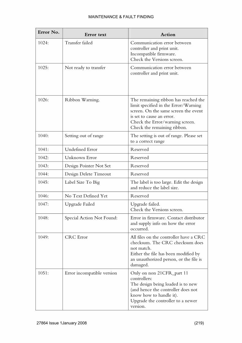
MAINTENANCE & FAULT FINDING
Error No. Error text Action
1024: Transfer failed error between print unit.
ware. creen.
Communicationcontroller and Incompatible firmCheck the Versions s
1025:
Not ready to transfer controller and print unit. Communication error between
1026: Ribbon Warning. reached the rror/Warning reen the event
screen. e remaining ribbon.
The remaining ribbon has limit specified in the Escreen. On the same scis set to cause an error. Check the Error/warning Check th
1040: Setting out of range The setting is out of range. Please set to a correct range
1041: eserved Undefined Error R
1042: Unknown Error Reserved
1043: Design Pointer Not Set Reserved
1044: imeout eserved Design Delete T R
1045: o Big el is too large. Edit the design el size.
Label Size T The laband reduce the lab
1046: No Text Defined Yet Reserved
1047: Upgrade Failed pgrade failed. UCheck the Versions screen.
1048: Special Action Not Found he error
: Error in firmware. Contact distributorand supply info on how toccurred.
1049: CRC Error l files on the controller have a CRC C checksum does
match. odified by
or the file is
Alchecksum. The CRnotEither the file has been man unauthorized person,damaged.
1051: Error incompatible versiocontrollers: The design being loaded is to new (and hence the controller does not know how to handle it). Upgrade the controller to a newer version.
n Only on non 21CFR_part 11
27864 Issue 1January 2008 (219)

MAINTENANCE & FAULT FINDING
Error No. Error text Action
1052: Error incompatible versio lers: is to new
er does not or to old hecksum).
Upgrade the controller to a newer
n Only on part 11 controlThe design being loaded(and hence the controllknow how to handle it) (created without CRC c
version.
1053: log type g feature. Error unknown Problems with the lo
1054: Error log id missing Problems with the log feature.
1060: check the File not found A file is not found. Pleasefilename.
1061: No external flash detected tions require an external lash card is
Some operaflash card. No external fdetected. Abort the operation. If required insert a Compact Flash Card while the power is switched off.
1062: Error Writing File or while writing a file to disk. ErrCheck for free space.
1063: Low Space on System Dis The system disk is running low on
sferred to ler can consume a lot of
e file system (i.e., to power loss)
also be the case.
” function. Select or
ile” and
ld s
e to the tem).
elete/Migrate old user data or contact your distributor if you suspect
st fragments.
k free space. Databases and images tranthe controlspace. Lost fragments in thif an upgrade fails duecan
Go to the “Explorethe system disk (Flashdisk2 Flashdisk) and select “Fproperties. An info screen is shown. The Size + Free space shoucorrespond to the Total space.(there inewer an exact match dunature of the file sysD
lo
1064: Critical Low Space on System Disk
The system disk is running critically low on free space - see above.
1065: Not Enough Space on System Disk
Reserved
1066: Not Enough Space Reserved
(220) 27864 Issue 1 January 2008
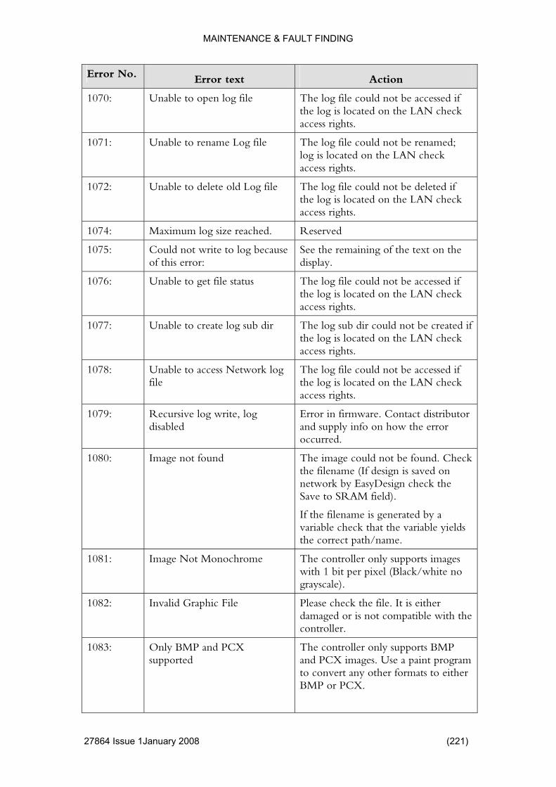
MAINTENANCE & FAULT FINDING
Error No. Error text Action
1070: Unable to open log file accessed if g is located on the LAN check
The log file could not be the loaccess rights.
1071: Unable to rename Log file be renamed; The log file could not log is located on the LAN check access rights.
1072: Unable to delete old Log log file could not be deleted if e log is located on the LAN check
file The thaccess rights.
1074: m log size reache Reserved Maximu d.
1075: log beof this error:
text on the Could not write to cause See the remaining of the display.
1076: Unable to get file status The log file could not be accessed if the log is located on the LAaccess rights.
N check
1077: d be created if AN check
s rights.
Unable to create log sub ir The log sub dir could notthe log is located on the Lacces
1078: etwork cessed if LAN check
cess rights.
Unable to access Nfile
log The log file could not be acthe log is located on theac
1079: Recursive log write, log disabled
distributor the error
Error in firmware. Contact and supply info on howoccurred.
1080: Image not found be found. Check ved on
asyDesign check the
he filename is generated by a
The image could not the filename (If design is sanetwork by ESave to SRAM field).
If tvariable check that the variable yieldsthe correct path/name.
1081: Image Not Monochrome e controller only supports images Thwith 1 bit per pixel (Black/white no grayscale).
1082: Invalid Graphic File damaged or is not compatible with the controller.
Please check the file. It is either
1083: Only BMP and PCX supported
The controller only supports BMP and PCX images. Use a paint program to convert any other formats to either BMP or PCX.
27864 Issue 1January 2008 (221)

MAINTENANCE & FAULT FINDING
Error No. Error text Action
1084: Error Reading Image ther aged or is not compatible with the
Please check the file. It is eidamcontroller.
1090: Help file not found tly selected ound. Select English.
The help file for the currenlanguage is not f
1091: Screen file Invalid Help The help file is damaged.
1092: Help text empty. No help text is entered for a particular item
1093: und. ed for a particular Help tag not fo No help text is enteritem
1100: Circular Reference nother riable that in turn depends on the
thus be
heck the variables dependencies
A variable depends on avafirst variable. None of the variables canevaluated. C
1101: Out of range prompt is ified in the
hin the range, ccept
The value typed in at theout of the range specvariable. Type in a number witor modify the design to aanother range.
1102: Invalid Value not be The typed in value could interpreted.
1103: rs e characters ariable.
ters, or modify e characters.
Too many characte The user has typed in morthan specified by the vType in fewer characthe design to accept mor
1104: Only numeric characters allowed
haracters are allowed. dify the
ard text.
Only numeric cType in a number or modesign to support stand
1105: Variable Not Supported A design containing a variable type is loaded.
to salvage gn to
permanently remove the variable.
that is no longer supported The variable is removed. Use the original programthe variable or save the desi
1106: Error writing continues sequence file
The sequence variable can be set to resume count. Check for access rights.
1107: Error loading continues sequence file
The sequence variable can be set to resume count. Check for access rights.
(222) 27864 Issue 1 January 2008
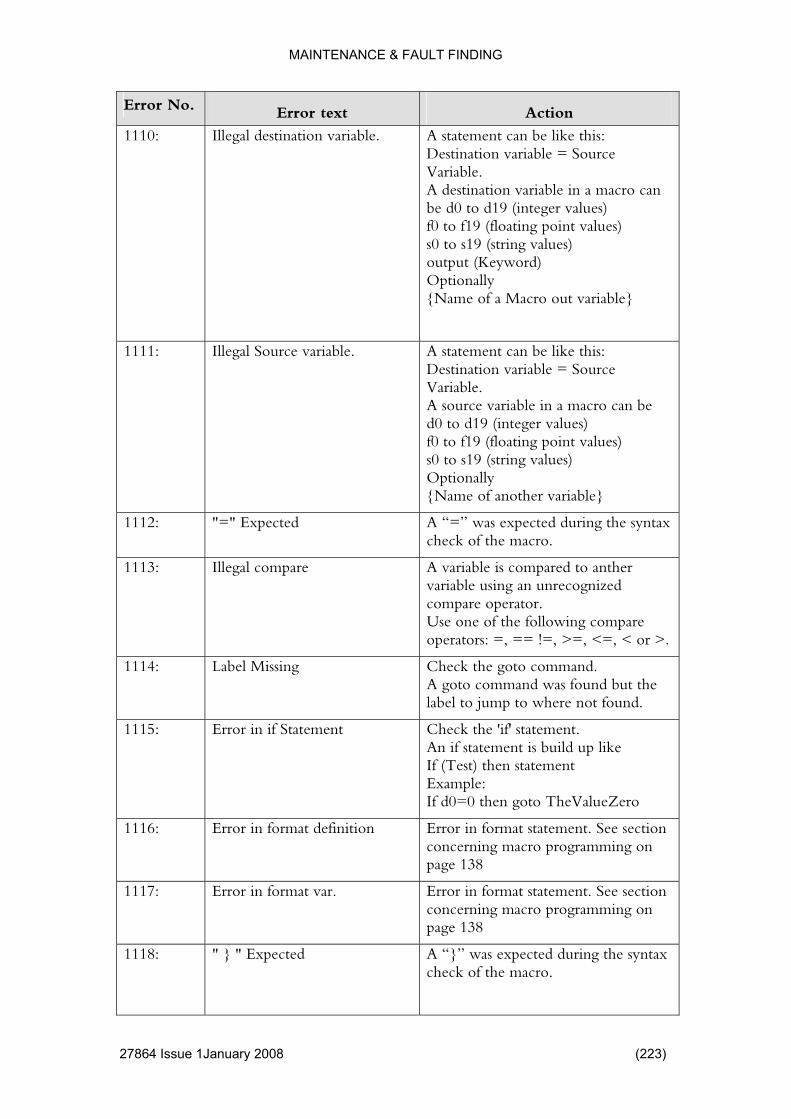
MAINTENANCE & FAULT FINDING
Error No. Error text Action
1110: Illegal destination variable ike this: estination variable = Source
e in a macro can values)
ting point values) o s19 (string values)
Optionally {Name of a Macro out variable}
. A statement can be lDVariable. A destination variablbe d0 to d19 (integerf0 to f19 (floas0 toutput (Keyword)
1111: Illegal Source variable. is: urce
ble in a macro can be to d19 (integer values)
point values)
iable}
A statement can be like thDestination variable = SoVariable. A source variad0 f0 to f19 (floating s0 to s19 (string values) Optionally {Name of another var
1112: "=" Expected during the syntax A “=” was expected check of the macro.
1113: Illegal compare ther unrecognized
g compare = !=, >=, <=, < or >.
A variable is compared to anvariable using an compare operator. Use one of the followinoperators: =, =
1114: Label Missing mand. nd was found but the
not found.
Check the goto comA goto commalabel to jump to where
1115: t p like
(Test) then statement
eZero
Error in if Statemen Check the 'if' statement. An if statement is build uIfExample: If d0=0 then goto TheValu
1116: Error in format definition rror in format statement. See section ming on
Econcerning macro programpage 138
1117: Error in format var. Error in format statement. See section concerning macro programming on page 138
1118: " } " Expected A “}” was expected during the syntax check of the macro.
27864 Issue 1January 2008 (223)
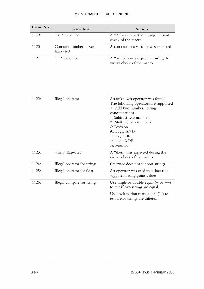
MAINTENANCE & FAULT FINDING
Error No. Error text Action
1119: " > " Expected expected during the syntax A “>” was check of the macro.
1120: ant number or var. A constant or a variable was expected. ConstExpected
1121:
" " " Expected syntax check of the macro. A “ (quote) was expected during the
1122: Illegal operator operators are supported
An unknown operator was found The following +: Add two numcon-: Subt*: Mu/: Divi&: Logic AND
bers (string catenation)
ract two numbers ltiply two numbers sion
|: Logic OR ^: Logic XOR %: Modulo
1123: uring the macro.
"then" Expected A “then” was expected dsyntax check of the
1124: Illegal operator for strings Operator does not support strings.
1125: Illegal operator for float t does not t values.
An operator was used thasupport floating poin
1126: Illegal compare for strings Use single or double equal (= or ==) to test if two strings are equal.
Use exclamation mark equal (!=) to test if two strings are different.
(224) 27864 Issue 1 January 2008

MAINTENANCE & FAULT FINDING
Error No. Error text Action
1127: 't compare string and number
d to a , first convert one
ther type using a
d s0, do
as strings (using s1 as temp):
If s1==s0 then… OR Compare as numbers (d1 as
Can A string can’t be comparenumber. If neededtype to anotemporary variable. If needed to compare d0 anone of the following: Compares1 = d0
temp) d1=s0 If d1==d0 then…
1128:
Max Loop Count executed more than 1000 times and
ved, the macro ered a
The error comes up to prevent a faulty macro to halt the entire unit. Check for endless loops.
If any of the statements in the macro is a result is not yet achieis considered to have entdeadlock.
1129: Variable Not Found A reference is made to another
variable
variable using the {Variable Name}syntax. Check that the referencedexists
1130: "output" Expected rs.
The keyword output was expected. Check for syntax erro
1131: Variable or Const Expecte riable or a constant (number or expected.
heck for syntax errors.
d A vatext) wasC
1133: Unknown System Var A reference is made to a system riable Name>
Check the name.
variable using the <Vasyntax.
1134: Macro Value Overwritten Not used
1135: Variable index out of range A local variable is indexed out of range. Range is from 0 to 19 (i.e. d0-d19)
27864 Issue 1January 2008 (225)
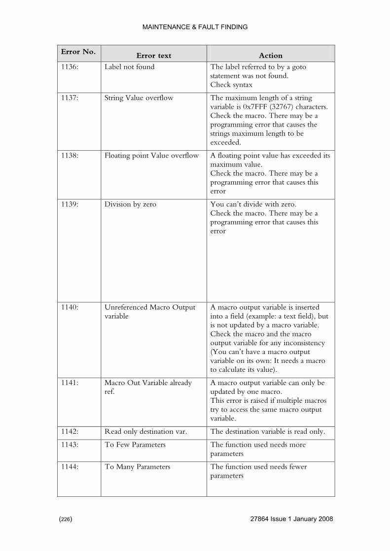
MAINTENANCE & FAULT FINDING
Error No. Error text Action
1136: Label not found d to by a goto ent was not found.
The label referrestatemCheck syntax
1137: String Value overflow string 7) characters.
e may be a gramming error that causes the
The maximum length of a variable is 0x7FFF (3276Check the macro. Therprostrings maximum length to be exceeded.
1138: Floating point Value over as exceeded its
Check the macro. There may be a r that causes this
flow A floating point value hmaximum value.
programming erroerror
1139:
Division by zero You can’t divide with zero. Check the macro. There may be a programming error that causes this error
1140: Unreferenced Macro Outvariable
inserted t field), but
onsistency utput ds a macro
o calculate its value).
put A macro output variable is into a field (example: a texis not updated by a macro variable. Check the macro and the macro output variable for any inc(You can’t have a macro ovariable on its own: It neet
1141: alread an only be o.
is error is raised if multiple macros macro output
Macro Out Variable y A macro output variable cref. updated by one macr
Thtry to access the samevariable.
1142: Read only destination var The destination variable is read only. .
1143: To Few Parameters The function used needs more parameters
1144: To Many Parameters The function used needs fewer parameters
(226) 27864 Issue 1 January 2008
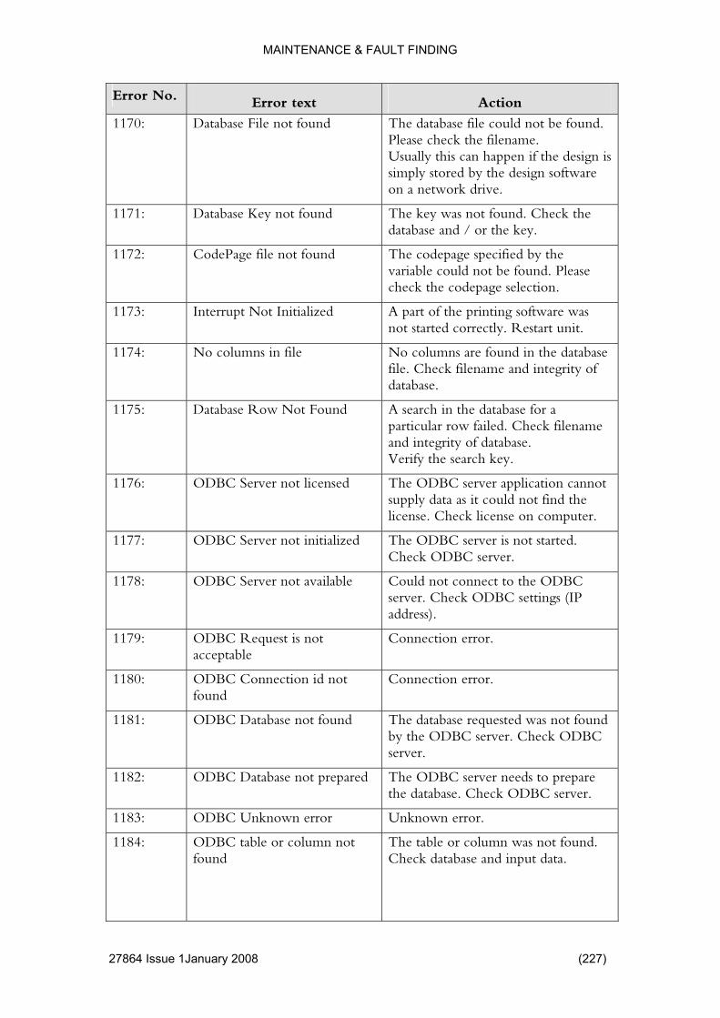
MAINTENANCE & FAULT FINDING
Error No. Error text Action
1170: Database File not found could not be found.
the design is d by the design software
The database filePlease check the filename. Usually this can happen ifsimply storeon a network drive.
1171: Database Key not found y.
The key was not found. Check the database and / or the ke
1172: CodePage file not found fied by the nd. Please
ction.
The codepage specivariable could not be foucheck the codepage sele
1173: Initialized are was art unit.
Interrupt Not A part of the printing softwnot started correctly. Rest
1174: No columns in file No columns are found in the database tegrity of file. Check filename and in
database.
1175: Database Row Not Found e database for a filename
.
A search in thparticular row failed. Checkand integrity of databaseVerify the search key.
1176: se lication cannot it could not find the
n computer.
ODBC Server not licen d The ODBC server appsupply data aslicense. Check license o
1177: ODBC Server not initializ started. C server.
ed The ODBC server is notCheck ODB
1178: Server not available Could not connect to the ODBC eck ODBC settings (IP
address).
ODBCserver. Ch
1179: t acceptable ODBC Request is no Connection error.
1180: ODBC Connection id not found
Connection error.
1181: ot foun base requested was not found by the ODBC server. Check ODBC
ODBC Database n d The data
server.
1182: ODBC Database not prepared The ODBC server needs to prepare the database. Check ODBC server.
1183: ODBC Unknown error Unknown error.
1184: ODBC table or column not found
The table or column was not found. Check database and input data.
27864 Issue 1January 2008 (227)

MAINTENANCE & FAULT FINDING
Error No. Error text Action
1185: ODBC error while execusql
while ing an SQL statement. Check
ting The ODBC server failed executODBC server.
1186: ODBC database not open tabase was not opened. Check The daODBC server.
1187: ODBC not activated The checkmark “ODBC Active” is not enabled.
1200: Serial variables buffer over variables input buffer was device that fills
flow The serial overflowed. Check the info into the buffer
1201: No active serial variables ccess a t exist. rnal device.
An external device tries to anamed: serial variable that does no
Check design and the exte
1202: ign transferred he transmission.
No active serial des A variable definition was out of scope. Check t
1203: nition t definition Error in input defi Syntax error in the inpu
1220: gn Ite ted. Error Creating Desi m The item could not be crea
1221: Error Creating Variable e variable could not be created. Th
1222: ype info about n. Check
Unknown Barcode T The barcode item containsa type currently not knowthe design.
1223:
Version ld not be read be damaged.
Check design.
Bad Label Design The design version coucorrectly. Design could
1224: Error Reading Design The design could not be loaded. Design could be damagedesign. Possibly an incorrect file
d. Check
name was specified. Check filename.
1225: Unable to start printing duan error
countered e design. A in this case.
rrors.
e to At least one error was enduring the loading of thprint cannot be printed Check the preceding e
1226: Printing halted due to an error s encountered in the s halted the
print. Check the preceding errors.
An error waprinting process that ha
1227: Error Reading Design One (or more) fields could not be read. Design could be damaged. Check design.
1228: Unknown error while reading design
Design could be damaged. Check design.
(228) 27864 Issue 1 January 2008
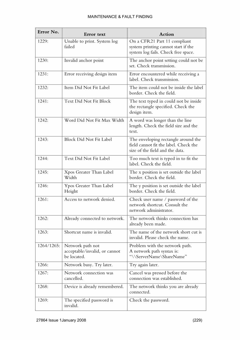
MAINTENANCE & FAULT FINDING
Error No. Error text Action
1229: nable to print. System lofailed
ompliant start if the
space.
U g On a CFR21 Part 11 csystem printing cannot system log fails. Check free
1230: Invalid anchor point int setting could not be The anchor poset. Check transmission.
1231: Error receiving design item Error encountered while receiving a label. Check transmission.
1232: abel de the label Item Did Not Fit L The item could not be insiborder. Check the field.
1241: Text Did Not Fit Block text typed in could not be inside . Check the
Thethe rectangle specifieddesign item.
1242: Word Did Not Fit Max Width A word was longer than the line and the length. Check the field size
text.
1243: Label around the it the label. Check the
a.
Block Did Not Fit The enveloping rectanglefield cannot fsize of the field and the dat
1244: t Did Not Fit Label is typed in to fit the Tex Too much textlabel. Check the field.
1245: Xpos Greater Than Label The x position is set outside the label Width border. Check the field.
1246: Ypos Greater Than Label is set outside the label The y positionHeight border. Check the field.
1261: Access to network denied r name / password of the the
r.
. Check usenetwork shortcut. Consult network administrato
1262: Already connected to network. The network thinks coalready been ma
nnection has de.
1263: Shortcut name is invalid. The name of the network short cut is invalid. Please check the name.
1264/126 rk path not network path. me”
5: Netwo Problem with the acceptable/invalid, or cannot be located.
A network path syntax is:“\\ServerName\ShareNa
1266: later. ter. Network busy. Try Try again la
1267: work connection was cancelled.
Cancel was pressed before the connection was established.
Net
1268: Device is already remembered. The network thinks you are already connected.
1269: The specified password is invalid.
Check the password.
27864 Issue 1January 2008 (229)
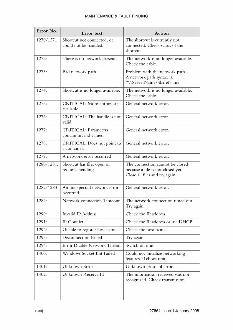
MAINTENANCE & FAULT FINDING
Error No. Error text Action
1270/127 nected, ocould not be handled.
ntly not nnected. Check status of the
1 Shortcut not con r The shortcut is currecoshortcut.
1272: There is no network prese ork is no longer available. nt. The netwCheck the cable.
1273: Bad network path. twork path. me”
Problem with the neA network path syntax is:“\\ServerName\ShareNa
1274: ai is no longer available. Check the cable.
Shortcut is no longer av lable. The network
1275: ailable.
CRITICAL: More entrieav
s are General network error.
1276: andle CRITICAL: The hvalid.
is not General network error.
1277: CRITICAL: Parameters General network error. contain invalid values.
1278: CRITICAL: Does na container.
ot po int to General network error.
1279: A network error occurred error. General network
1280/1281: Shortcut has files open orequests pending.
r n cannot be closed The connectiobecause a file is not closed yet. Close all files and try again.
1282/128 d network e ork error. 3 An unexpecteoccurred.
rror General netw
1284: Network connection Timeout The network connection timed out. Try again
1290: Invalid IP Address Check the IP address.
1291: IP Conflict! Check the IP address or use DHCP
1292: Unable to register host na st name. me Check the ho
1293: on Failed Disconnecti Try again.
1294: twork TError Disable Ne hread Switch off unit
1400: Windows Socket Init Failed Could not initialize networking features. Reboot unit.
1401: Unknown Error Unknown protocol error.
1402: Unknown Receive Id The information received was not recognized. Check transmission.
(230) 27864 Issue 1 January 2008

MAINTENANCE & FAULT FINDING
Error No. Error text Action
1403: Unknown Send Id is not nized by the protocol. Check
The information to sendrecogtransmission.
1404: ETB Missing ntrol character is missing. Check A cotransmission.
1405: Unable to start receive thread Could not initialize networking features. Reboot unit.
1406: Init Serial port Could not open serial port. Try to g baud reopen the port by switchin
rate.
1407: Read Timeout as read, but
od of time. e.
The start of a command wthe remainder of the command was not received within a periCheck the sending devic
1408: Memory Allocation Failed Could not allocate enough memory.
1409: Write Timeout t data. The receiver does not accepCheck cable.
1410: Invalid Handle The internal handle used for the
r another cking the port.
transmission is invalid. Either the portwas not opened properly odevice is blo
1411: Error Creating send block t in blocks. One such block could not be created.
Any transmission is sen
Check transmission.
1412: Error Reading String A string was supposedly sent but the ize the
r the baud andshake.
receiver could not recognformat. Check transmission. Lowerate. Enable Hardware h
1413: teger posedly sent but nize the
r the baud andshake.
Error Reading In An integer was supthe receiver could not recogformat. Check transmission. Lowerate. Enable Hardware h
1414: Error Reading Double A floating point number was supposedly sent but the receiver could not recognize the format. Check transmission. Lower the baud rate. Enable Hardware handshake.
27864 Issue 1January 2008 (231)

MAINTENANCE & FAULT FINDING
Error No. Error text Action
1415: Error Reading data as supposedly receiver could not
er the baud e handshake.
A block of raw data wsent but the recognize the format. Check transmission. Lowrate. Enable Hardwar
1416: Version Conflict or the .
The software in the unitexternal device is to old
1417: munication error. Try again. Unexpected Answer Com
1418: Failed To Receive Command Check cable.
1419: Error Parsing Block Buffer Check transmission.
1420: Block k transmission. Invalid Socket Data Chec
1421: o Send Command Check cable. Failed T
1422: losing connection Handshake failed c Check cable.
1423: Socket ident is not valid le used for the ither the port
pened properly or another evice is blocking the port
The internal handtransmission is invalid. Ewas not od
1424: l is too old external Client protoco Check versions. Upgradedevice if required.
1425: The socket is already in use Try later
1426: Invalid host address No unit with the specified name or address could be found. Check name
nnection. and network co
1427: new sock oot unit. Unable to create et Try again. Reb
1428: ket gain. Reboot unit. Unable to connect soc Try a
1429: The socket is not connected Try again. Reboot unit.
1430: Invalid socket package Try again. Reboot unit.
1431: Unable to start listen threa eboot unit. d R
1432: th ot unit. Error terminating listen read Rebo
1433: t socket Unable to accep Not used
1434: Printer protocol is too old unit if required.
Check versions. Upgrade
1435: Error starting network socket Reboot unit.
1436: Unknown Setting Id Check transmission
1437: Failed to allocate socket command data block
Could not allocate enough memory. Try again. Reboot unit.
(232) 27864 Issue 1 January 2008
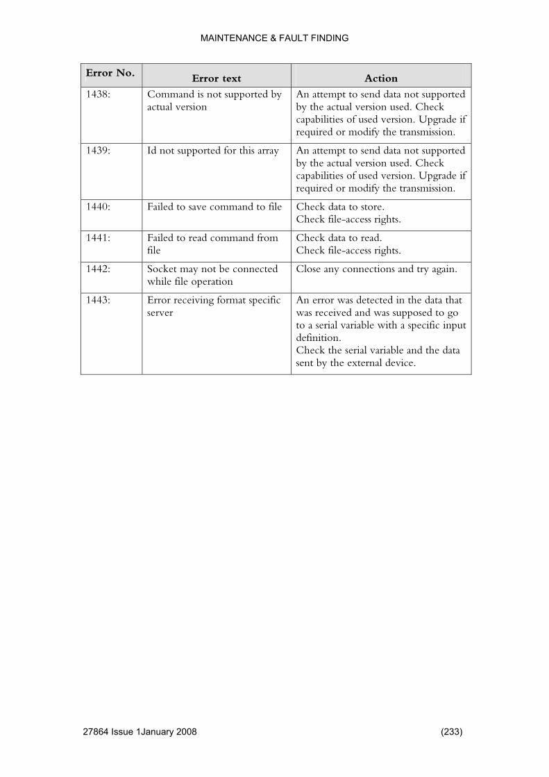
MAINTENANCE & FAULT FINDING
Error No. Error text Action
1438: d is not supporteactual version
not supported heck
. Upgrade if smission.
Comman d by An attempt to send databy the actual version used. Ccapabilities of used versionrequired or modify the tran
1439: Id not supported for this a supported heck
f dify the transmission.
rray An attempt to send data notby the actual version used. Ccapabilities of used version. Upgrade irequired or mo
1440: t to store. ss rights.
Failed to save command o file Check dataCheck file-acce
1441: fCheck file-access rights.
Failed to read commandfile
rom Check data to read.
1442: eile file operation
try again. Socket may not be connwh
cted Close any connections and
1443: Error receiving format speserver
error was detected in the data that osed to go
with a specific input definition. Check the serial variable and the data sent by the external device.
cific Anwas received and was suppto a serial variable
27864 Issue 1January 2008 (233)

MAINTENANCE & FAULT FINDING
ELECTRICAL Problem Action
No light showing in display on power up The power switch must be in tposition. T
he ON his switch is located at the rear
ck that the mains cable is correctly nector below
on the fuse ay and replace if necessary.
230VAC and
ns supply to the V ER. There may
r supply.
of the Controller. Cheinserted into the mains conthe switch. Check that the mains fuse selector is okThe fuse is 3.15AT for 6,30AT for 115VAC Check the maiSERIES CONTROLLbe another fuse installed to protect the Mains Cable at source. 8 A fuse defect on powe
The Controller is functioning but there is no print reaction
Incorrect printer selection. Go to settings in the menu, click hardware, click printer type and chose the correct printer.
(234) 27864 Issue 1 January 2008

MAINTENANCE & FAULT FINDING
PRINT QUALITY AND PRINT HEAD Problem Action
No Information is Printed perating tly but no data is printed, check
ed and darkness levels for the
te.
head coming into full n / roller
from the print head
e pressure.
ters the encoder signal may not be providing the correct speed information.
The print head may be faulty.
If the printer appears to be ocorrecthe following:
Is a valid layout selected?
Check the print spevalues are at appropriatethermal ribbon and substra
Is the print contact with the print plateacross its full width?
Is the correct ribbon loaded with the inked surface away and is it driving correctly?
Check the air supply is at theappropriat
On continuous prin
27864 Issue 1January 2008 (235)
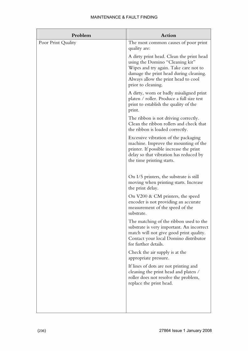
MAINTENANCE & FAULT FINDING
Problem Action
Poor Print Quality most common causes of poor print
n the print head g kit” re not to
ring cleaning.
isaligned print platen / roller. Produce a full size test
ty of the
check that .
ackaging ove the mounting of the
printer. If possible increase the print s reduced by
ate is still rts. Increase
e print delay.
speed ccurate
f the
e ribbon used to the ortant. An incorrect
o distributor
supply is at the appropriate pressure.
If lines of dots are not printing and cleaning the print head and platen / roller does not resolve the problem, replace the print head.
Thequality are:
A dirty print head. Cleausing the Domino “CleaninWipes and try again. Take cadamage the print head duAlways allow the print head to cool prior to cleaning.
A dirty, worn or badly m
print to establish the qualiprint.
The ribbon is not driving correctly. Clean the ribbon rollers andthe ribbon is loaded correctly
Excessive vibration of the pmachine. Impr
delay so that vibration hathe time printing starts.
On I/5 printers, the substrmoving when printing stath
On V200 & CM printers, theencoder is not providing an ameasurement of the speed osubstrate.
The matching of thsubstrate is very impmatch will not give good print quality. Contact your local Dominfor further details.
Check the air
(236) 27864 Issue 1 January 2008
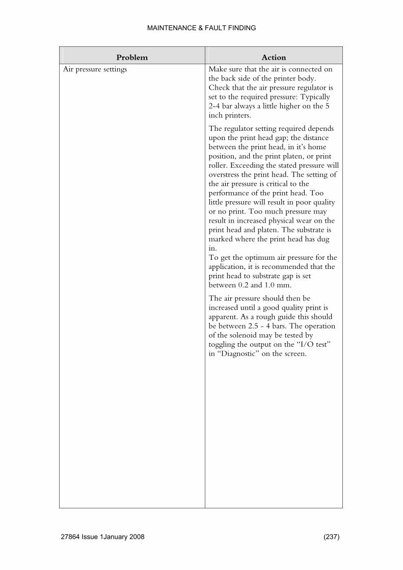
MAINTENANCE & FAULT FINDING
Problem Action
Air pressure settings
s connected on ody.
regulator is : Typically
r always a little higher on the 5
ired depends e distance
home , or print
ed pressure will e setting of the d. Too oor quality
ssure may result in increased physical wear on the
bstrate is has dug
mended that the s set
then be ty print is
guide this should be between 2.5 - 4 bars. The operation of the solenoid may be tested by toggling the output on the “I/O test” in “Diagnostic” on the screen.
Make sure that the air ithe back side of the printer bCheck that the air pressure set to the required pressure2-4 bainch printers.
The regulator setting requupon the print head gap; thbetween the print head, in it’sposition, and the print platenroller. Exceeding the statoverstress the print head. Ththe air pressure is critical to performance of the print healittle pressure will result in por no print. Too much pre
print head and platen. The sumarked where the print headin. To get the optimum air pressure for the application, it is recomprint head to substrate gap ibetween 0.2 and 1.0 mm.
The air pressure shouldincreased until a good qualiapparent. As a rough
27864 Issue 1January 2008 (237)

MAINTENANCE & FAULT FINDING
Problem Action
Print darkness
els should be set in
d is high, ay have to be raised
ty.
the print d accordingly.
vels should ed and ill allow.
print-head life um. Contrast
also
when
l for any
e damaged available,
raising the contrast level may be enough to spread the heat to effectively close the gap. This would allow the printer to be used while a new print head arrived.
Print contrast levrelation to the print speed.
For example, if the print speethe print contrast mto achieve good print quali
If the print speed is loweredcontrast should be reduceAs a general rule contrast lebe kept as low as the line speprint quality requirements wThis will ensure that thewill be used to its optimlevels that are too high may contribute to poor print quality or ribbon breakage (especiallyprinting bar-codes or horizontal lines).
The maximum contrast leveprint speed is 120%.
If a print head dot has becomand no replacement is readily
(238) 27864 Issue 1 January 2008

MAINTENANCE & FAULT FINDING
Problem Action
Faded print nt quality is dependent on the
lity of the substrate and ribbon used,
eing used to
ns of the
kept clean by no cleaning kit. It should uched with any abrasive
jects.
ions:
rint head and platen
Increase the air pressure
Prifollowing:
Quabeing
Print contrast
Air pressure and print speed combination
Condition of the machine bprint
The age and storage conditioribbon can also affect the print quality. The print head should beusing Dominever be tomaterial or metallic ob
Recommendat
Clean the p
Increase the contrast
Reduce the print speed
Reduce print ratio.
Review ribbon.
Faded on one side
ue to a misalignment
own to will hit one
pad first. Recommendations:
Check that the print head / not loose, especially if it has just been replaced.
Align the printer correctly.
This is generally dof the printer to the platen roller/ pad. The print head will move dprint on the substrate, andside of the roller/
27864 Issue 1January 2008 (239)

MAINTENANCE & FAULT FINDING
Problem Action
Print rubs off
f reasons:
going to ent in cold
he Darkness the
levels of the head
perature ribbon may
ill be warm and could rub off. Trying ld be the
bstrate. Some ke it very tings may
sin mix n. If this is the
sk your r ribbon
This can be for a number o
There is not enough energy the head. This is more apparenvironments. Increasing tand in extreme conditions,background energycan make a difference to the permeability.
In environments of high temand humidity, the applied sta different ribbon grade cousolution.
Mismatch in ribbon/ susubstrate has coatings that madifficult to adhere to. The coabe, for example, a wax/ resimilar to the actual ribbocase, then trying another ribbon grade is the best recommendation. Alocal Domino distributor foadvises.
Ribbon Creasing ue to the ack’ across the
n causes
Bent ribbon guide pins. This may occur
ible to bend a pin back into e the guide
ff roller. Remove and
nment can creasing as
ribbon across the print head.
Ribbon creasing is generally dribbon attempting to ‘trprint head. The most commoare:
if the cassette is dropped. It is not usually possposition. Remove and replacpin.
A bent peel oreplace the peel bar.
Poor print platen / roller aligin some cases cause ribbonthe substrate tries to pull the
Print roller/ platen
If the print roller has become damaged this will cause print quality problems. A flat spot on the roller will appear as a repeated blank area on the Test pattern.
(240) 27864 Issue 1 January 2008

MAINTENANCE & FAULT FINDING
Problem Action
Encoder
tating CM will not print
er signal is sending V SERIES
the
Check that the encoder is rofreely. The V200 & unless the encoder is moving.
Check that the encoda signal back to theCONTROLLER using“Diagnostic”-“sensor test”
Ribbon Drive Problems
oo high or the ibbon can be
and break. This can be ness or
taking up the
een the lated wasted ribbon and any
y. Ensure gripping
If the print darkness is tprint Speed too low, the rweakenedeliminated by reducing the darkincreasing the speed.
The ribbon rewind is notwaste ribbon correctly. Check that there is no interference betwaccumuother part of the printer bodthat the waste ribbon spool isthe core firmly.
Missing front edge of the print out
Increase run
s included. rt that the Y-
Head down time is too short. the head down time step by step in 'settings' until the front edge iShould the controller repooffset is to short please increase its value.
The reaction length is tooan overlap between two prinused ribbon.
long creating ts on the
e reaction be showing an incorrect
image of how much the ribbon is being pulled back as it will slide of the spool.
If the driver roller is greasy thlength will
Rear edge of print out is missing
Head up time is too long. Decrease the time in run settings.
27864 Issue 1January 2008 (241)

MAINTENANCE & FAULT FINDING
Problem Action
There are unprinted lines in the print
remove and we aning
rint out. r to another
might be necessary to change the counter
r simply clean
ct print sign in
ossible .
Clean the print head.
Dirt can be difficult to recommend a thorough cle
Any scratches on the rubber platen or rubber roller will effect the pPlease move the printeposition with no scratches. It
pressure platen or roller oit.
You have one or more defedots. Try and move the deposition x to an area where the defect dot is not being used. If not pplease change the print head
Printout is periodically missing and thprinter creates a flopping sound whileprinting
ir ced. It is
r pressure ead is out of
contact with the counter pressure platen/roller as this can result in a more rapid burn out off the print head.
e
The air pressure is too powerful and aregulation must be reduimportant not to lower the aiso much that the print h
(242) 27864 Issue 1 January 2008
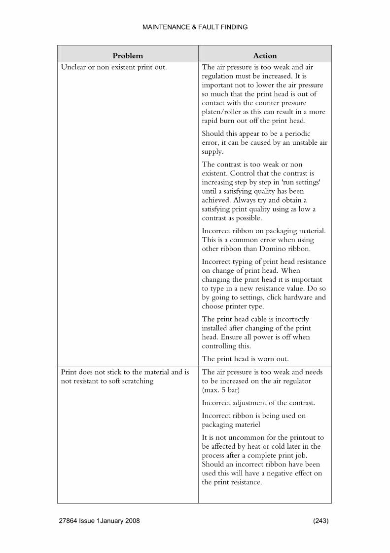
MAINTENANCE & FAULT FINDING
Problem Action
Unclear or non existent print out.
eak and air . It is
air pressure is out of sure
int head.
Should this appear to be a periodic by an unstable air
non e contrast is
un settings' s been
as low a
g material. or when using
ibbon.
resistance f print head. When
it is important e value. Do so hardware and
printer type.
le is incorrectly e print
off when rolling this.
t.
The air pressure is too wregulation must be increasedimportant not to lower theso much that the print head contact with the counter presplaten/roller as this can result in a more rapid burn out off the pr
error, it can be caused supply.
The contrast is too weak orexistent. Control that thincreasing step by step in 'runtil a satisfying quality haachieved. Always try and obtain a satisfying print quality using contrast as possible.
Incorrect ribbon on packaginThis is a common errother ribbon than Domino r
Incorrect typing of print headon change ochanging the print head to type in a new resistancby going to settings, clickchoose
The print head cabinstalled after changing of thhead. Ensure all power iscont
The print head is worn ou
Print does not stick to the material annot resistant to soft scratching
eak and needs
the contrast.
d on
It is not uncommon for the printout to be affected by heat or cold later in the process after a complete print job. Should an incorrect ribbon have been used this will have a negative effect on the print resistance.
d is The air pressure is too wto be increased on the air regulator (max. 5 bar)
Incorrect adjustment of
Incorrect ribbon is being usepackaging materiel
27864 Issue 1January 2008 (243)

MAINTENANCE & FAULT FINDING
Problem Action
A large part or parts of the print out imissing.
Remove e and make sure there are no
There are more defect dots in the print
s The ribbon is double layered.the cartridgfolds on the ribbon.
head
There is shading/smudging on the firpart of print out
long. Reduce
pear please et' step by
t is obtained.
st Head down time is too this in 'run settings' until the front edge is clean
Should the smudging still apincrease the 'Motor start off sstep until a satisfying resul
There is shading/smudging on the lasof print out
Head up time is too short. Increase this r edge is
Should the smudging still appear, increase the 'Motor stop off set' step by step until a satisfying result is obtained.
t part in 'run settings' until the reaclean
Display shows 'print head interface not done'
tmode. Please do this by 'run settings'
The print speed is above 1000 mm/sec and it is necessary to activate the fas- 'Quality'
The ribbon is breaking
erful and the air
r.
oo powerful after ibbon economy whilst
This is
d
ontrast is too high
The ribbon economy has been reduced but the contrast has not. It is very
The air pressure is too powwill need to be reduced onregulato
The air pressure is tactivating the rnot reducing the air pressure.very important.
The ribbon spool is damage
The c
important to follow this through when activating the ribbon economy functionality.
The packaging machine is signalling print Incorrect connection of the print signal.
(244) 27864 Issue 1 January 2008
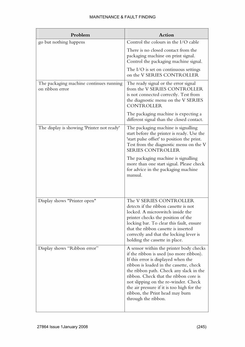
MAINTENANCE & FAULT FINDING
Problem Action
go but nothing happens
I/O cable
ct from the signal.
hine signal.
s TROLLER
Control the colours in the
There is no closed contapackaging machine on print Control the packaging mac
The I/O is set on continuous settingon the V SERIES CON
The packaging machine continues ruon ribbon error
or signal ROLLER
nected correctly. Test from V SERIES
expecting a d contact.
nning The ready signal or the errfrom the V SERIES CONTis not conthe diagnostic menu on theCONTROLLER
The packaging machine isdifferent signal than the close
The display is showing 'Printer not re
alling inter is ready. Use the
on the print. u on the V
more than one start signal. Please check for advice in the packaging machine
ady' The packaging machine is signstart before the pr'start pulse offset' to positiTest from the diagnostic menSERIES CONTROLLER
The packaging machine is signalling
manual.
Display shows "Printer open"
LLER e is not
ch inside the the t, ensure
is inserted g lever is
The V SERIES CONTROdetects if the ribbon cassettlocked. A microswitprinter checks the position oflocking bar. To clear this faulthat the ribbon cassette correctly and that the lockinholding the cassette in place.
Display shows “Ribbon error” body checks re ribbon).
when the aded in the cassette, check
the ribbon path. Check any slack in the ribbon. Check that the ribbon core is not slipping on the re-winder. Check the air pressure if it is too high for the ribbon, the Print head may burn through the ribbon.
A sensor within the printerif the ribbon is used (no moIf this error is displayedribbon is lo
27864 Issue 1January 2008 (245)
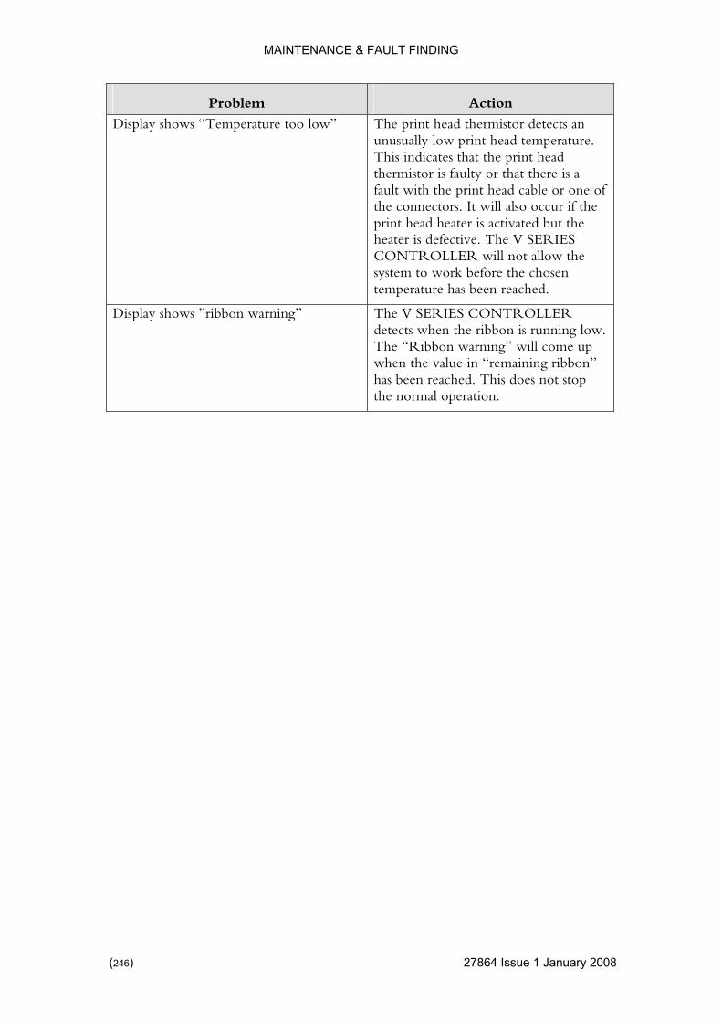
MAINTENANCE & FAULT FINDING
Problem Action
Display shows “Temperature too low etects an d temperature.
nt head re is a
le or one of occur if the ed but the
V SERIES ill not allow the
e chosen .
” The print head thermistor dunusually low print heaThis indicates that the prithermistor is faulty or that thefault with the print head cabthe connectors. It will alsoprint head heater is activatheater is defective. The CONTROLLER wsystem to work before thtemperature has been reached
Display shows ”ribbon warning” LLER unning low.
ill come up when the value in “remaining ribbon” has been reached. This does not stop the normal operation.
The V SERIES CONTROdetects when the ribbon is rThe “Ribbon warning” w
(246) 27864 Issue 1 January 2008
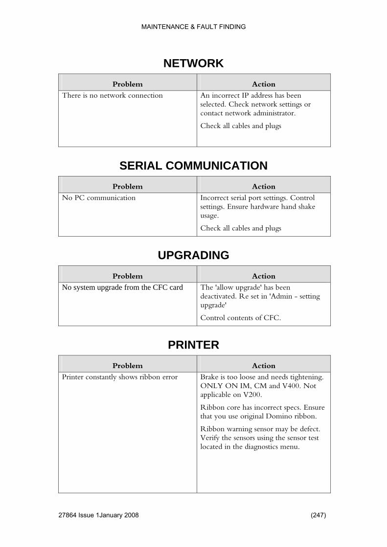
MAINTENANCE & FAULT FINDING
NETWORK Problem Action
There is no network connection
as been rk settings or
administrator.
Check all cables and plugs
An incorrect IP address hselected. Check netwocontact network
SERIAL COMMUNI ON CATIProblem Action
No PC communication ardware hand shake
usage.
eck all cables and plugs
Incorrect serial port settings. Control settings. Ensure h
Ch
UPGRADING Problem Action
No system upgrade from the CFC card The 'allow upgrade' has been deactivated. Re set in 'Admin - setting upgrade'
Control contents of CFC.
PRINTER Problem Action
Printer constantly shows ribbon erro tightening. 400. Not
Ribbon core has incorrect specs. Ensure that you use original Domino ribbon.
Ribbon warning sensor may be defect. Verify the sensors using the sensor test located in the diagnostics menu.
r Brake is too loose and needsONLY ON IM, CM and Vapplicable on V200.
27864 Issue 1January 2008 (247)
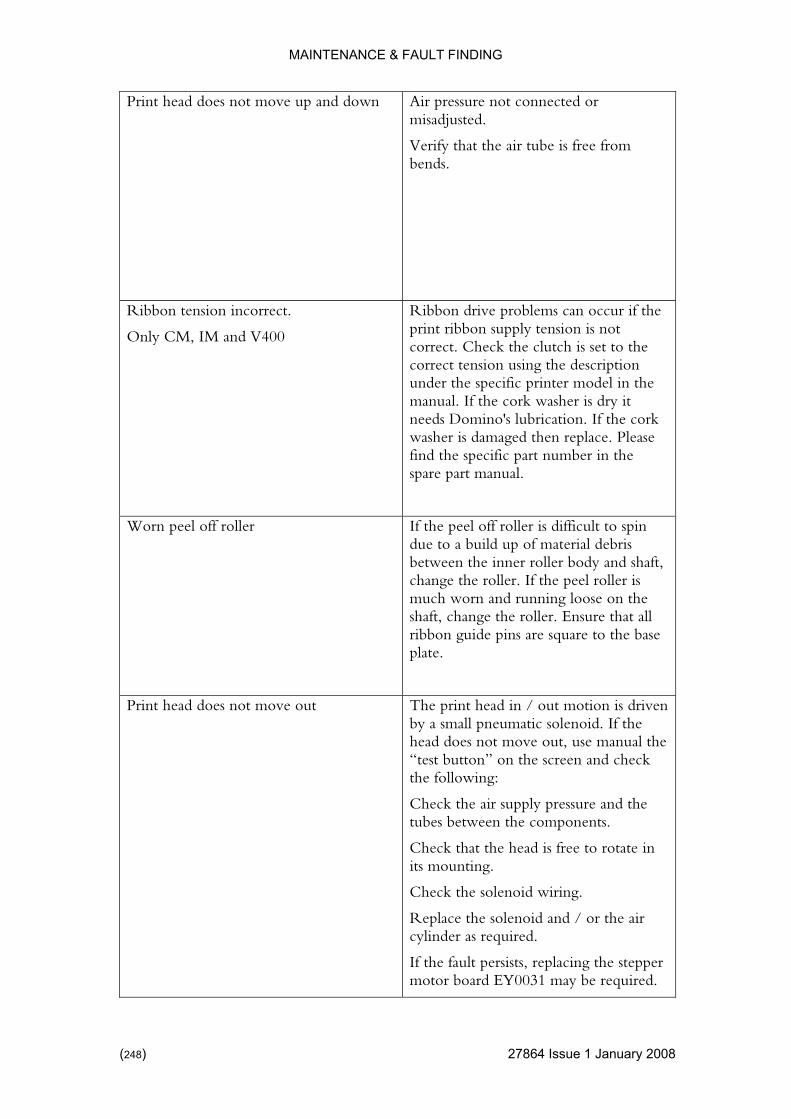
MAINTENANCE & FAULT FINDING
Print head does not move up and do
ressure not connected or
Verify that the air tube is free from bends.
wn Air pmisadjusted.
Ribbon tension incorrect.
Only CM, IM and V400
occur if the is not set to the ription del in the
r is dry it ino's lubrication. If the cork
washer is damaged then replace. Please
Ribbon drive problems canprint ribbon supply tension correct. Check the clutch is correct tension using the descunder the specific printer momanual. If the cork washeneeds Dom
find the specific part number in the spare part manual.
Worn peel off roller ult to spin l debris y and shaft,
change the roller. If the peel roller is much worn and running loose on the
se
If the peel off roller is difficdue to a build up of materiabetween the inner roller bod
shaft, change the roller. Ensure that allribbon guide pins are square to the baplate.
Print head does not move out
tion is driven
nd check
ents.
rotate in
Check the solenoid wiring.
Replace the solenoid and / or the air cylinder as required.
If the fault persists, replacing the stepper motor board EY0031 may be required.
The print head in / out moby a small pneumatic solenoid. If the head does not move out, use manual the “test button” on the screen athe following:
Check the air supply pressure and the tubes between the compon
Check that the head is free toits mounting.
(248) 27864 Issue 1 January 2008
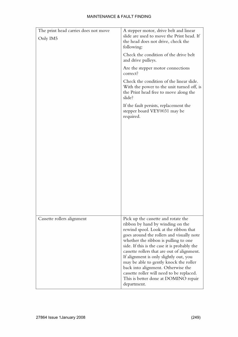
MAINTENANCE & FAULT FINDING
The print head carries does not move
Only IM5
d linear e Print head. If
head does not drive, check the
e condition of the drive belt
onnections
linear slide. With the power to the unit turned off, is
ve along the
the fault persists, replacement the stepper board VEY0031 may be required.
A stepper motor, drive belt anslide are used to move ththefollowing:
Check thand drive pulleys.
Are the stepper motor ccorrect?
Check the condition of the
the Print head free to moslide?
If
Cassette rollers alignment te the n the
ibbon that visually note g to one
bably the tte rollers that are out of alignment.
If alignment is only slightly out, you may be able to gently knock the roller back into alignment. Otherwise the cassette roller will need to be replaced. This is better done at DOMINO repair department.
Pick up the cassette and rotaribbon by hand by winding orewind spool. Look at the rgoes around the rollers and whether the ribbon is pullinside. If this is the case it is procasse
27864 Issue 1January 2008 (249)

MAINTENANCE & FAULT FINDING
RIBBON BREAKS Problem Action
Ribbon breaks may be caused by onethe following issues.
e is not set ribbon to
ak. See how
of Check that the cassette braktoo tight. This can cause thestretch, and eventually breto adjust the break under the specific printer (p. 167). ONLY CM, IM & V400
Check that the encodersubstrate speed correctly, oribbo
is matching the therwise the
n may be dragged out of the reak. ONLY
s stationary. IM5 & V400
Check that the energy to the print head is not too high.
printer and eventually bCM & V200
Check that the Domino printer is printing whilst the substrate iONLY
(250) 27864 Issue 1 January 2008
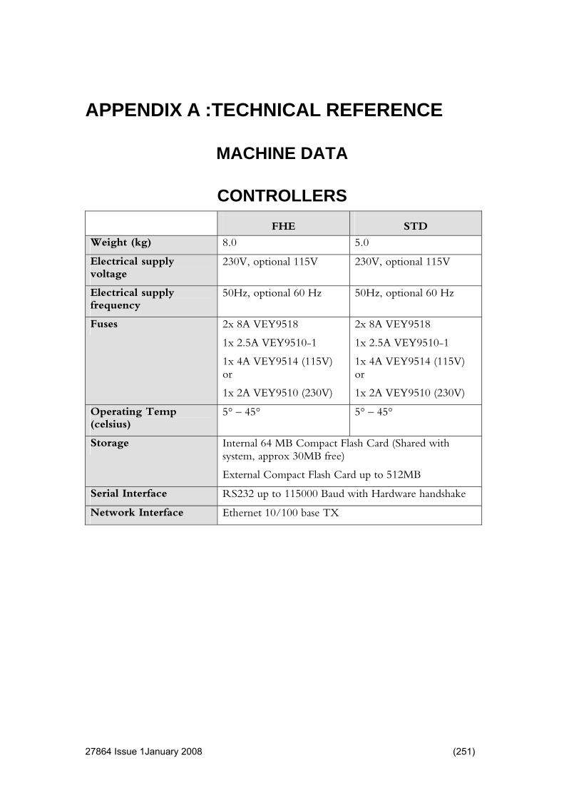
MACHINE DATA
CONTROLLERS
APPENDIX A :TECHNICAL REFERENCE
FHE STD
Weight (kg) 8.0 5.0
Electrical supply 230V, optional 115V nal 115V 230V, optiovoltage
Electrical supply frequency
ional 60 H ptional 60 Hz 50Hz, opt z 50Hz, o
Fuses
0-
4A VEY9514 (11or
18
9510-1
1x 4A VEY9514 (115V) or
9510 (230V)
2x 8A VEY9518 2x 8A VEY95
1x 2.5A VEY951 1 1x 2.5A VEY
1x 5V)
1x 2A VEY9510 (230V) 1x 2A VEY
Operating Temp (celsius)
5° – 45° 5° – 45°
Storage Internal 64 MB Compact Flash Card (Shared with B free)
External Compact Flash Card up to 512MB
system, approx 30M
Serial Interface RS232 up to 115000 Baud with Hardware handshake
Network Interface Ethernet 10/100 base TX
27864 Issue 1January 2008 (251)
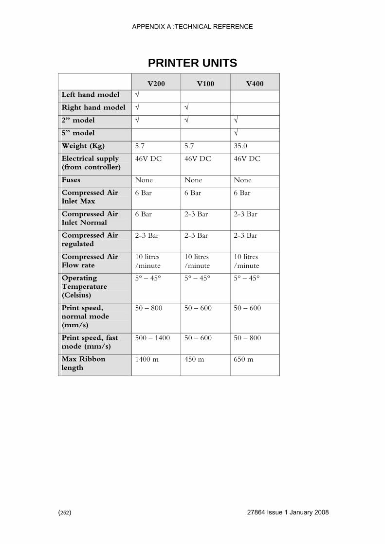
APPENDIX A :TECHNICAL REFERENCE
PRINTER UNITS
V200 V100 V400
Left hand model √
Right hand mod √ √ el
2” model √ √ √
5” model √
Weight (Kg) 5.7 5.7 35.0
Electrical supply ler
6V DC 46V D 46V DC 4 C (from control )
Fuses None None None
Compressed Air 6 Bar Bar 6 Bar 6Inlet Max
Compressed Air 6 Bar 2-3 Bar 2-3 Bar Inlet Normal
Compressed Air regulated
Bar 3 Ba 2-3 Bar 2-3 2- r
Compressed Air ate
10 litres /minute
10 litres /minute
10 litres /minute Flow r
Operating 5° – 45° 5° – 45° 5° – 45° Temperature (Celsius)
Print speed, normal mode (mm/s)
50 – 800 50 – 600 50 – 600
Print speed, fast mode (mm/s)
500 – 1400 50 – 600 50 – 800
Max Ribbon length
1400 m 450 m 650 m
(252) 27864 Issue 1 January 2008

APPENDIX A :TECHNICAL REFERENCE
PRINTING DATA Max Print area 2” model 53 x 106 mm
Max Print area 5” model (V200 128 x 2700 mm) (V400 128x580)
Material PE – PP – PA – PET – paper, Tyvek™, cellophane, etc
Print resolution = 300 x 300 dpi300 dpi
Normal mode: 12 x 12 dots / mmFast Mode: 6 x 12 dots / mm = 150 x
Truetype Fonts ans MS,
icrosoft NSimSun, Times New
ebdings, RV OCRA III,
B III, MRV ted under a
are Inc.
Arial, Arial black, Arial Narrow, Comic SCourier New, Gautami,
Georgia, Gulim, Impact, Kino MT, Latha, MLogo, MS Gothic, MS PGothic, Mangal, Raavi, Shruti, SimSun, Symbol, Tahoma,Roman, Trebuchet MS, Tunga, Veranda, WWindings; The fonts MRV OCRA I, MMRV OCRA IV, MRV OCRB I, MRV OCROCRB IV, OCR A and OCR B are distribulicensing agreement with Morovia Softw
Barcodes trix, DUN 14, n, Interleaved
14, ITF SCC 14, GS1 DATABAR , GS1 DATABAR Truncated, GS1 DATABAR Stacked, GS1 DATABAR Stacked Omni directional, GS1 DATABAR Limited, GS1 DATABAR Expanded, UPC A, UPC E.
Codabar, Code 128, Code 39, DataMaEAN 128, EAN 13, EAN 8, EAN Add o2 of 5, ITF
27864 Issue 1January 2008 (253)
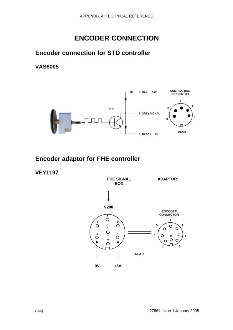
APPENDIX A :TECHNICAL REFERENCE
(254) 27864 Issue 1 January 2008
ION
Encoder connection for STD controller
005
Encoder adaptor for troller
VEY1197 FHE SIGNAL
BOX ADAPTOR
0V +5V
ENCODER CONNECT
VAS6
FHE con
V200
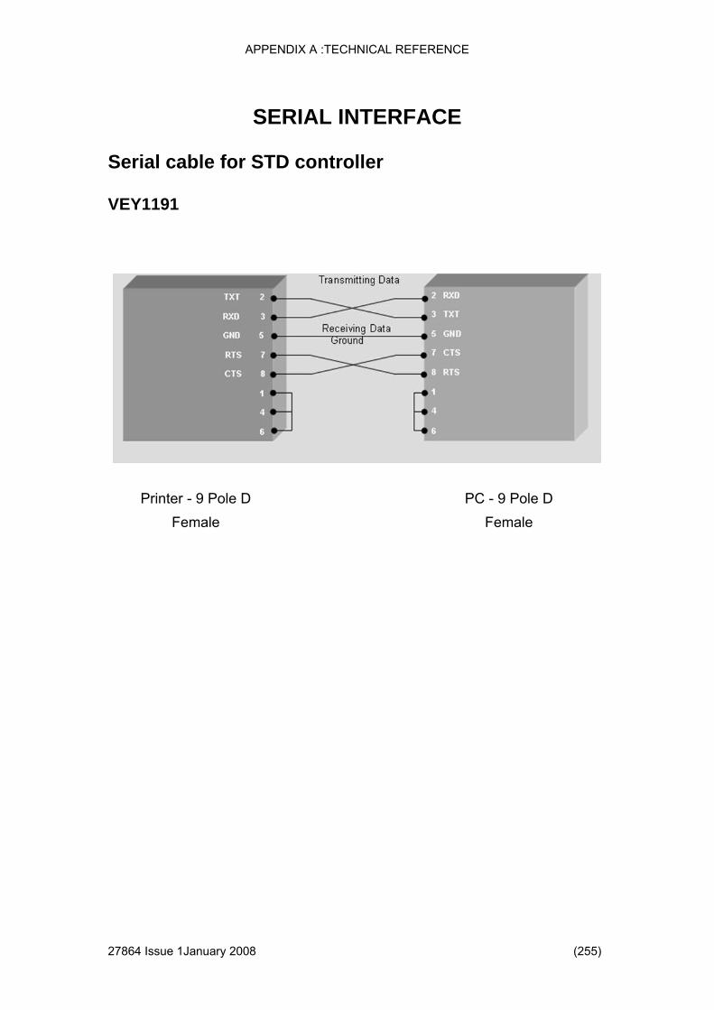
APPENDIX A :TECHNICAL REFERENCE
27864 Issue 1January 2008 (255)
CE
Serial cable for STD controller
VEY1191
SERIAL INTERFA
Printer - 9 Pole D Female
PC - 9 Pole D Female

APPENDIX A :TECHNICAL REFERENCE
THIS PAGE INTENTIONALLY LEFT BLANK
(256) 27864 Issue 1 January 2008

CONTENTS
Page
261
.........264
.........265
.........265
.........266
.........266
.........266
.........266
267
.........268
.........269
.........270
.........270
.........270
.........270
.........271
271
.........272
.........272
.........272
.........272
.........273
.........275
Inserting a Line Item.............................................................................275
Inserting a Picture Item ........................................................................276
Inserting a TTF Item .............................................................................277
Inserting a Text Item.............................................................................278
APPENDIX B : EASYDESIGN MANUAL
MENU MAP ............................................................................................INSTALLATION .............................................................................
Uninstalling EasyDesign..............................................................Upgrading EasyDesign................................................................
USING EASYDESIGN...................................................................Creating a New Design ...............................................................Opening a Design........................................................................Saving a Design ..........................................................................Printing .................................................................................................Setting up a Printer Driver ...........................................................Setting up the Serial Ports...........................................................
EDITING A DESIGN......................................................................Editing Label Attributes ...............................................................Editing a Design Item ..................................................................Editing Variables .........................................................................View Only ....................................................................................Show Approved ....................................................................................
DESIGN ITEMS.............................................................................General Settings for Design Items...............................................Rotation.......................................................................................Anchor Point................................................................................Inserting a Barcode Item .............................................................Inserting a Box Item ....................................................................
27833 Issue 1January 2007 (257)

APPENDIX B: EASYDESIGN MANUAL
DESIGN VARIABLES .............................................................................279
.........279
.........280
.........281
.........282
.........282
.........283
.........283
284
.........285
.........286
.........287
.........287
.........288
.........288
..........288
289
.........289
.........289
.........290
.........290
.........290
.........290
Approval ...............................................................................................290
Setting up Users and Passwords .........................................................290
Version Information ..............................................................................290
Database.....................................................................................Database Field ............................................................................Macro ..........................................................................................Macro Output...............................................................................Serial ...........................................................................................Database.....................................................................................Machine ID ..................................................................................Prompted..............................................................................................Sequential ...................................................................................Shift Code....................................................................................Time/Date....................................................................................User ID ........................................................................................Selecting Multiple Items ..............................................................Aligning Items..............................................................................Rotating Items ............................................................................Centre Items.........................................................................................Size Items....................................................................................Space Items ................................................................................
MISCELLANEOUS ........................................................................Changing Language ....................................................................Validate .......................................................................................Changing Options........................................................................
(258) 27864 Issue 1 January 2008

APPENDIX B: EASYDESIGN MANUAL
Amendment Record Issue 1 March 2007
27833 Issue 1January 2007 (259)

APPENDIX B: EASYDESIGN MANUAL
THIS PAGE INTENTIONALLY LEFT BLANK
(260) 27864 Issue 1 January 2008
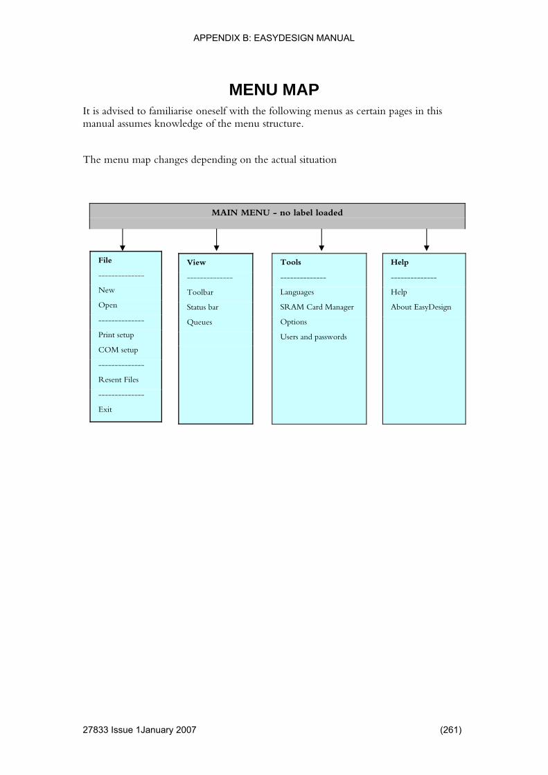
APPENDIX B: EASYDESIGN MANUAL
27833 Issue 1January 2007 (261)
llowing menus as certain pages in this manual assumes knowledge of the menu structure.
The menu map changes depending on the actual situation
MENU MAP It is advised to familiarise oneself with the fo
MAIN MENU - no label loaded
Help
--------------
Help
About EasyDesign
Tools
--------------
Languages
SRAM Card Manager
Options
Users and passwords
View
--------------
Toolbar
Status bar
Queues
File
--------------
New
Open
--------------
Print setup
COM setup
--------------
Resent Files
--------------
Exit

APPENDIX B: EASYDESIGN MANUAL
MAIN MENU - label loaded
Window
--------------
New Window
Cascade
Tile
Arrange Icons
--------------
Opened Windows
Objects
--------------
Align
Rotate
Centre
Size
Space Evenly
Break Apart (ESC)
View
--------------
Toolbar
Status bar
Queues
Show Approved
Next Design Item
Previous Design Item
Zoom In
Zoom Auto
Zoom Out
Refresh (F5)
File
--------------
New
Open
Close
Save
Save As
--------------
Print setup
COM setup
--------------
Resent Files
--------------
Exit
Tools
--------------
Languages
Validate
SRAM Card Manager
Options
Align 1mm boundary
Pharmaceutical label approval
Users and passwords
Help
--------------
Help
About EasyDesign
Insert Edit
-------------- --------------
Barcode Undo
Box --------------
Line Cut
Picture Copy
TTF Paste
Text Delete
Select All
--------------
Edit Label Attributes
Edit Design Item
Edit Variables
--------------
View Only
(262) 27864 Issue 1 January 2008

APPENDIX B: EASYDESIGN MANUAL
Tools
-------------
Languages
Options
View
-------------
Toolbar
Status bar
Queues
MAIN MENU - Print Queue View
Help
--------------
Help
About EasyDesign
File
--------------
New
Open
--------------
Print setup
COM setup
--------------
Resent Files
--------------
Exit
Queue
--------------
Start
Stop
Delete Queue Entry
Edit Queue Entry
Window
--------------
New Window
Cascade
Tile
Arrange Icons
--------------
Opened Windows
27833 Issue 1January 2007 (263)

APPENDIX B: EASYDESIGN MANUAL
(264) 27864 Issue 1 January 2008
syDesign on a computer simply run the Setup.exe, indicated by the following icon:
INSTALLATION To install Ea
EasyDesign Setup program
To handle the licence of EasyDesign a separate program, WIBU-KEY, is also installed.
The WIBU-KEY is accessible in the control panel:
Follow the instructions on the screen to complete the installation.
WIBU-KEY Icon

APPENDIX B: EASYDESIGN MANUAL
Uninstalling EasyDesign To uninstall EasyDesign do one of the following:
• Run the Setup.exe again and select "Remove".
EasyDesign Setup program
• Go to the control panel and select "Add/Remove programs". Select the EasyDesign icon. Press "Edit/Remove". Select "Remove" in the uninstaller.
EasyDesign Icon
Uninstalling EasyDesign will not remove the following items:
W B
s
Upgrading EasyDesign To upgrade EasyDesign, uninstall the old version first.
Once this has been uninstalled, the newer version can be installed.
I U-KEY
• User generated Designs • User generated Template• User installed printer drivers
27833 Issue 1January 2007 (265)

APPENDIX B: EASYDESIGN MANUAL
EasyDesign allows you to select from a template or create a blank design.
USING EASYDESIGN
Creating a New Design To create a new design press the "File | New" button.
Opening a Design esign will
sh to save your changes.
Press the "File | Save" button to save the changes. If the design has not yet been assigned a name, use the "Save As" function instead.
When wishing to save the design using another name use the "File | Save As". EasyDesign will prompt for a file name and path for the new design.
To open a previously saved design press the "File | Open" button. EasyDopen an Explorer window to locate the desired design.
Saving a Design When changes have been made to your design, you may wi
(266) 27864 Issue 1 January 2008

APPENDIX B: EASYDESIGN MANUAL
Printing Press the "File | Print" menu to open the print dialog.
The top section of the print dialog shows a list (Name) of available printerselect from. The list is made up of all the installed drivers filtered with the dcurrent design is created for. If the design is made for a V100 and you havV200 on a c
queues to river the
e installed a om port and a V100 on a com port only, the V200 queue will appear in
l transfer the
Use the Export function if you plan to store the design on a Compact Flash Card.
the list.
The normal procedure is to "Print to printer on specified port". This wildesign to the printer and initiate the print mode.
27833 Issue 1January 2007 (267)
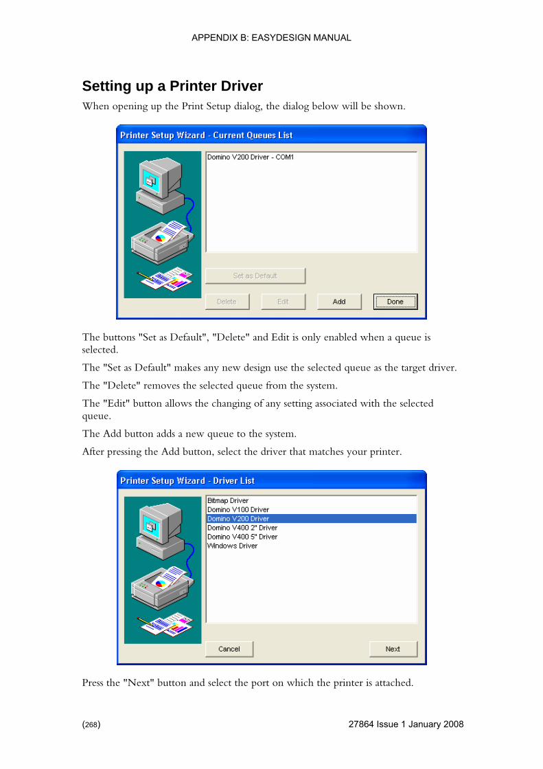
APPENDIX B: EASYDESIGN MANUAL
When opening up the Print Setup dialog, the dialog below will be shown.
Setting up a Printer Driver
The buttons "Set as Default", "Delete" and Edit is only enabled when a queue is selected.
Set as Default" makes any new design use the selected queue as the target driver.
rom the system.
ith the selected queue.
The Add button adds a new queue to the system.
After pressing the Add button, select the driver that matches your printer.
The "
The "Delete" removes the selected queue f
The "Edit" button allows the changing of any setting associated w
Press the "Next" button and select the port on which the printer is attached.
(268) 27864 Issue 1 January 2008

APPENDIX B: EASYDESIGN MANUAL
If the printer is attached using LAN, select the "socket" button, otherwise port from the list.
select the
If the socket button is pressed, type in the IP address of the printer (alternatively you ed to it).
EasyDesign will suggest a name for the queue.
Modify as required and complete with the "Done" button.
can use the Host name of the printer if one is assign
Setting up the Serial Ports To make sure the serial port settings match the settings of the printer, you may need to verify the settings in the "File - V200 setup" menu.
27833 Issue 1January 2007 (269)

APPENDIX B: EASYDESIGN MANUAL
t which driver the design is made for.
Further options include label size and run settings.
EDITING A DESIGN
Editing Label Attributes The label attributes dialog enables you to se
Editing a Design Item To modify one of the design items on the label, mark the item with tthe TAB key to select the next item.
he mouse or use
ld the shift key while selecting with the mouse.
osed it can be opened by double clicking the item or by
ayout of the "Edit window" depends on the actual item type.
bles" menu creation and editing of variables is possible in the design.
Design includes Time/Date variables, counter variables, and user prompted variables etc.
Insert a variable into a design item when the information to print is not determined at the time the label is created.
If an item is obstructed by an overlaying item, press and ho
If the edit window is clselecting the "Edit | Edit Design Item" menu.
The l
Editing Variables In the "Edit | Edit Varia
(270) 27864 Issue 1 January 2008

APPENDIX B: EASYDESIGN MANUAL
View Only not have privileges to modify the design. Please
see section concerning Users and Passwords.
n both an approved design and a design to
lace. When
ign before prin
Note: In standard mode the approving functions are not used and the function is therefore not relevant for some users.
The View Only option is set if you do
Show Approved A design can (but is not required to) contaibe modified.
When editing the design, modification of the non approved design takes prequired to print the approved design is printed.
The "View Approved" function allows the inspection of the approved desting.
27833 Issue 1January 2007 (271)
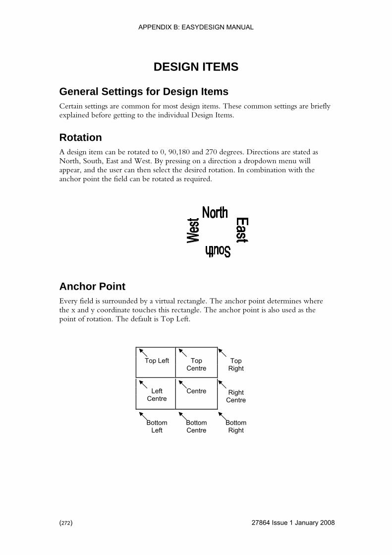
APPENDIX B: EASYDESIGN MANUAL
(272) 27864 Issue 1 January 2008
s. These common settings are briefly
re stated as on a direction a dropdown menu will
appear, and the user can then select the desired rotation. In combination with the anchor point the field can be rotated as required.
Every field is surrounded by a virtual rectangle. The anchor point determines where the x and y coordinate touches this rectangle. The anchor point is also used as the point of rotation. The default is Top Left.
DESIGN ITEMS
General Settings for Design Items Certain settings are common for most design itemexplained before getting to the individual Design Items.
Rotation A design item can be rotated to 0, 90,180 and 270 degrees. Directions aNorth, South, East and West. By pressing
Anchor Point
Top Centre
Top Right
Right Centre
Centre
Top Left
Left Centre
Bottom Left
Bottom Centre
Bottom Right

APPENDIX B: EASYDESIGN MANUAL
When this function is selected, a barcode is inserted into the design.
Inserting a Barcode Item
Special Functions:
• one is required as the first item in an EAN 128 code.
next AI.
• <A>, <B> and <C>: Change the encoding type of the Code/EAN 128 barcode. If none is selected, EasyDesign will select the encoding that generates the shortest code.
• | (Pipe): Used to separate primary and secondary data for an GS1 DATABAR barcode.
<F1>: Insert a <F1> for Function 1. This
A <F1> must also be used to separate a variable length AI with theExample:
The AI 10 is variable length.
<F1>1599121210LOT<F1>0112345678901231
27833 Issue 1January 2007 (273)

APPENDIX B: EASYDESIGN MANUAL
(274) 27864 Issue 1 January 2008
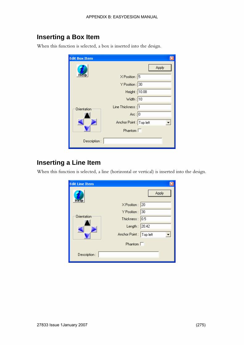
APPENDIX B: EASYDESIGN MANUAL
Inserting a Box Item When this function is selected, a box is inserted into the design.
Inserting a Line Item When this function is selected, a line (horizontal or vertical) is inserted into the design.
27833 Issue 1January 2007 (275)

APPENDIX B: EASYDESIGN MANUAL
When this function is selected, a picture is inserted into the design.
Inserting a Picture Item
When the "Store Internally" checkmark is activated a snapshot is taken oshown picture (with the current scaling as well). The snapshot is stored interthe Design file.
f the currently nally in
Doing so has a few benefits: There are fewer files after a ‘print to a printer’ is completed. You can easily copy the design afterwards as you do not need to worry about links to pictures. Modifications are easy to see in EasyDesign before the image is ready to be printed.
(276) 27864 Issue 1 January 2008

APPENDIX B: EASYDESIGN MANUAL
Inserting a TTF Item When this function is selected, a True Type Font text item is inserted into the design.
The TTF item has three different ways of controlling the enveloping rectangle in w i
• e width and height of the field. The minimum and maximum font size can be specified by the "Min Pt" and "Max
dth and height of the TTF items increase automatically when required.
• Normal: The height and width of the field is fixed.
esired text
h ch the text is displayed.
Size to fit: The font size is adjusted to fit th
Pt" • Auto Expand: The wi
If, for some reason, there is not enough space in the field to display the dthen the field is show in red color.
TTF item have furthermore the option of adjusting the distance (in pixels) between the individual characters as well as stretching or compressing the font (Font Width Adjust in percent).
27833 Issue 1January 2007 (277)

APPENDIX B: EASYDESIGN MANUAL
When this function is selected, an ABC text item is inserted into the design.
Inserting a Text Item
An ABC Text item uses the printers built in fonts. The appropriate font (Bitmap or Vector) is selectable in the dialog.
Note that V Series based thermal coders uses True Type fonts and does not have any specific built in fonts, and ABC Text items is therefore not supported by V series coders.
(278) 27864 Issue 1 January 2008
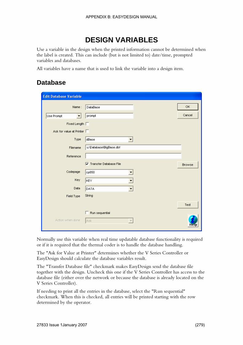
APPENDIX B: EASYDESIGN MANUAL
DESIGN VARIABLES Use a variable in the design when the printed information cannot be dthe label is created.
etermined when This can include (but is not limited to) date/time, prompted
link the variable into a design item.
Database
variables and databases.
All variables have a name that is used to
Normally use this variable when real time updatable database functionality ior if it is required that the thermal coder is to handle the database handling.
The "Ask for Valu
s required
e at Printer" determines whether the V Series Controller or
together with the design. Uncheck this one if the V Series Controller has access to the database file (either over the network or because the database is already located on the V Series Controller).
If needing to print all the entries in the database, select the "Run sequential" checkmark. When this is checked, all entries will be printed starting with the row determined by the operator.
EasyDesign should calculate the database variables result.
The "Transfer Database file" checkmark makes EasyDesign send the database file
27833 Issue 1January 2007 (279)
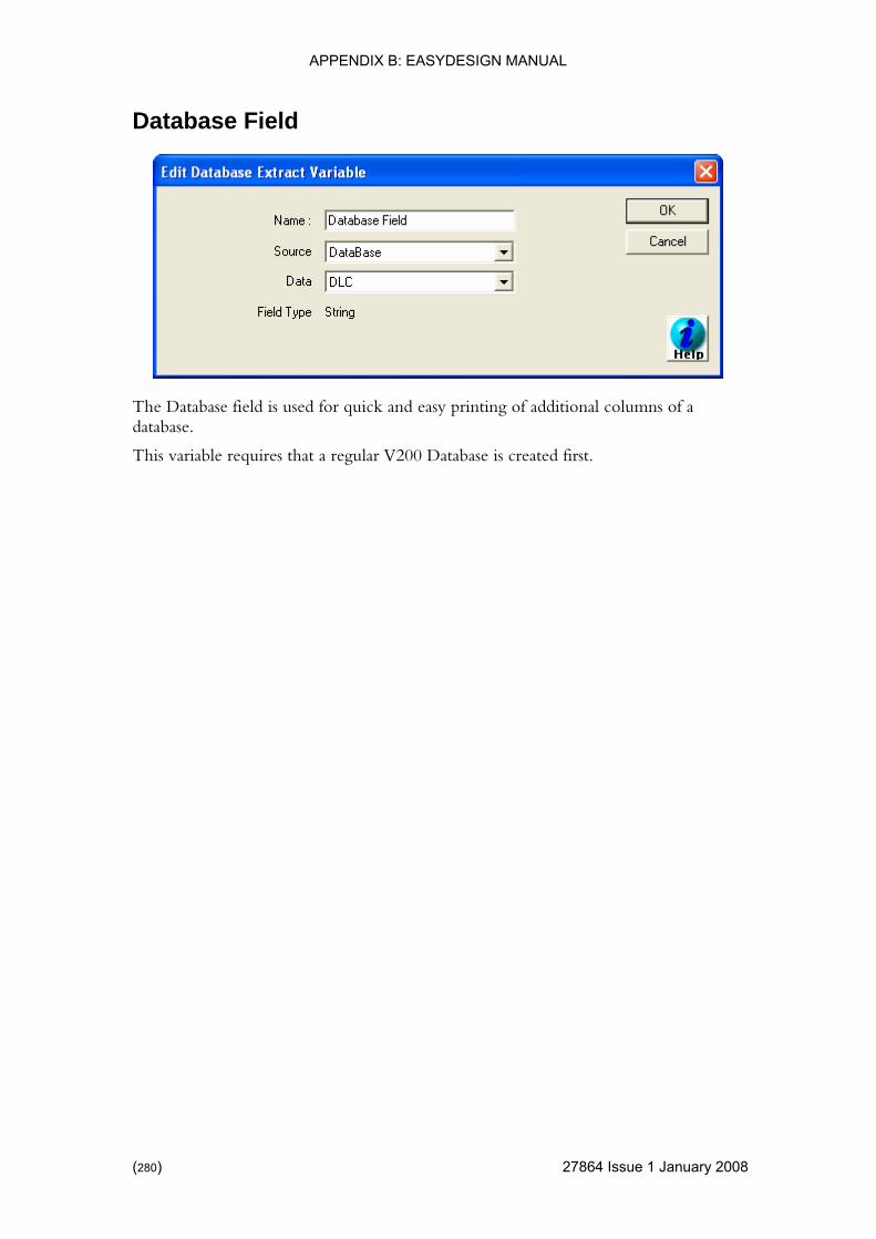
APPENDIX B: EASYDESIGN MANUAL
ld Database Fie
The Database field is used for quick and easy printing of additional columns of a database.
This variable requires that a regular V200 Database is created first.
(280) 27864 Issue 1 January 2008

APPENDIX B: EASYDESIGN MANUAL
Macro
The macro variable is a small programming language in itself. The macro is commonly used when an advanced variable is required. Macros can be used to calculate specific checksums, convert from one kind of input to another more desired format to print.
After typing in the macro, you can test the macro by pressing the test button. The macro is now checked for correct syntax and the macro is evaluated. Note that if the macro depends on other variables these are not evaluated first.
27833 Issue 1January 2007 (281)

APPENDIX B: EASYDESIGN MANUAL
duce more than one result is required, you need to use the Macro output variable type.
Macro Output If a macro to pro
In the macro definition enter:
Output}="The result"
Serial
{Macro
Use a serial variable when the V Series Controller is connected to external equipment (such as a scale) that transmits print data to the V Series Controller during a job.
(282) 27864 Issue 1 January 2008
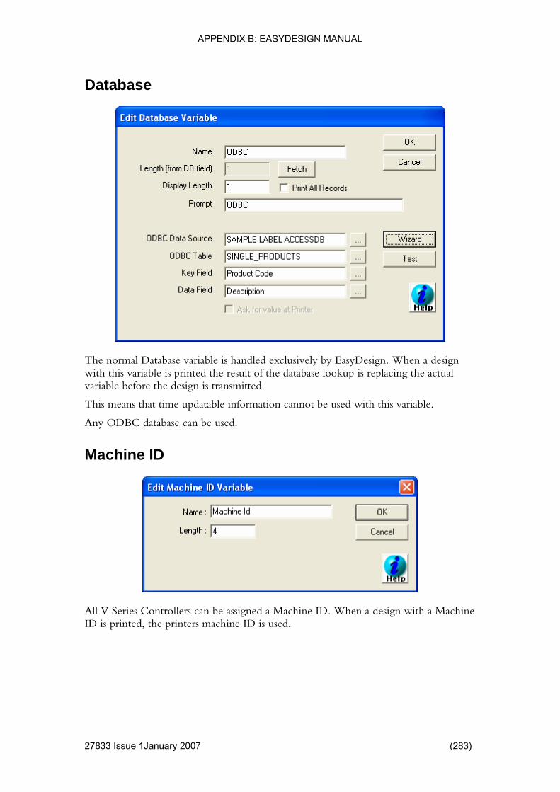
APPENDIX B: EASYDESIGN MANUAL
Database
The normal Database variable is handled exclusively by EasyDesign. When a design e result of the database lookup is replacing the actual
variable before the design is transmitted.
t time updatable information cannot be used with this variable.
Any ODBC database can be used.
Machine ID
with this variable is printed th
This means tha
All V Series Controllers can be assigned a Machine ID. When a design with a Machine ID is printed, the printers machine ID is used.
27833 Issue 1January 2007 (283)
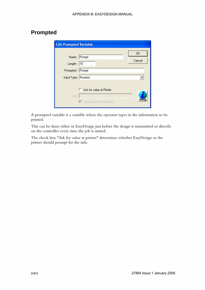
APPENDIX B: EASYDESIGN MANUAL
Prompted
A prompted variable is a variable where the operator types in the information to be printed.
This can be done either in EasyDesign just before the design is transmitted or directly on the controller every time the job is started.
The check box "Ask for value at printer" determines whether EasyDesign or the printer should prompt for the info.
(284) 27864 Issue 1 January 2008
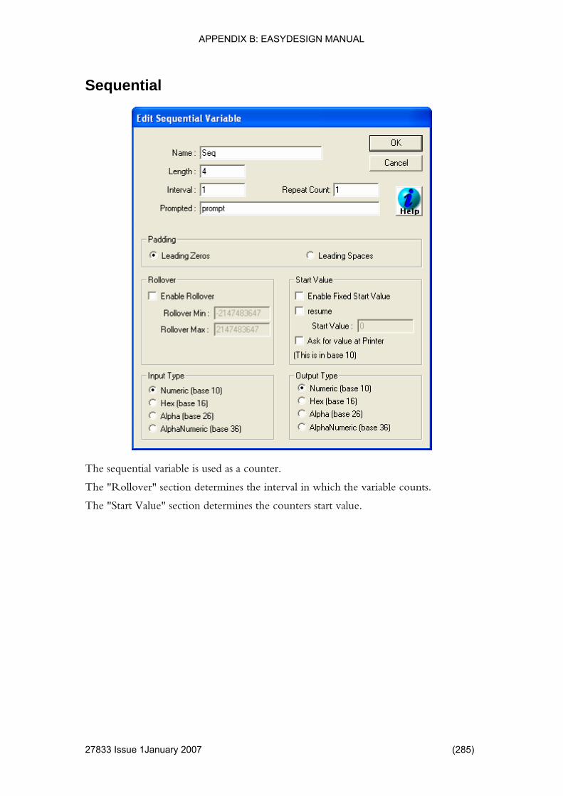
APPENDIX B: EASYDESIGN MANUAL
Sequential
The sequential variable is used as a counter.
The "Rollover" section determines the interval in which the variable counts.
The "Start Value" section determines the counters start value.
27833 Issue 1January 2007 (285)

APPENDIX B: EASYDESIGN MANUAL
Shift Code
In the shift code variable, a set of time slots is defined. During printing the V Series Controller selects the "Shift Text" that matches the current time slot and then prints that text.
(286) 27864 Issue 1 January 2008
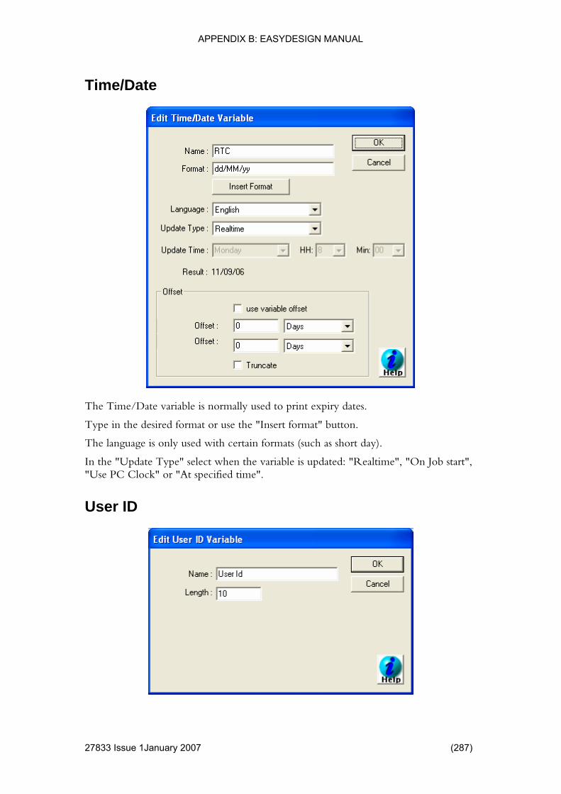
APPENDIX B: EASYDESIGN MANUAL
Time/Date
The Time/Date variable is normally used to print expiry dates.
Type in the desired format or use the "Insert format" button.
age is only used with certain formats (such as short day).
In the "Update Type" select when the variable is updated: "Realtime", "On Job start", "Use PC Clock" or "At specified time".
User ID
The langu
27833 Issue 1January 2007 (287)
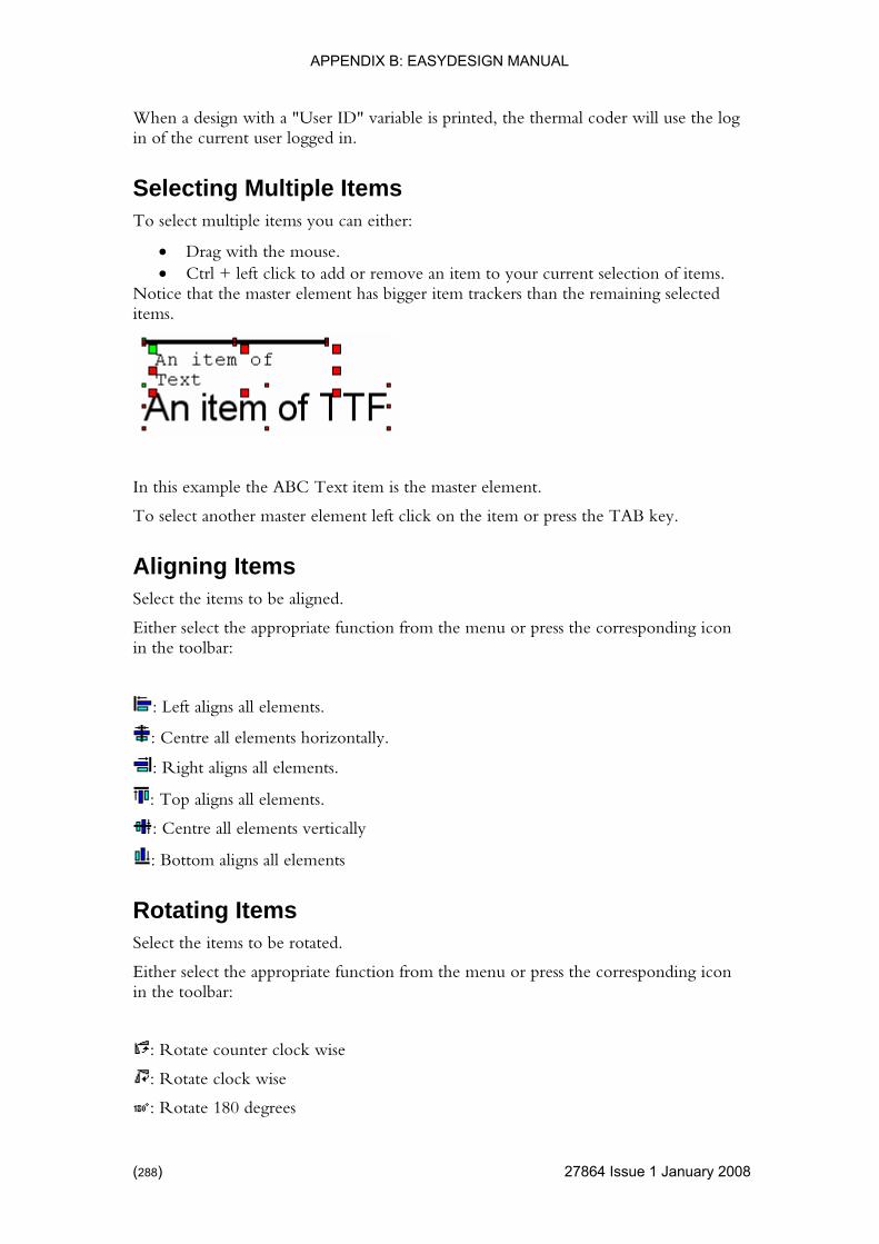
APPENDIX B: EASYDESIGN MANUAL
r ID" variable is printed, the thermal coder will use the log in of the current user logged in.
s To select multiple items you can either:
Ctrl + left click to add or remove an item to your current selection of items. Notice that the master element has bigger item trackers than the remaining selected items.
When a design with a "Use
Selecting Multiple Item
• Drag with the mouse. •
In this example the ABC
To select another m
Text item is the master element.
aster element left click on the item or press the TAB key.
Select the items to be aligned.
riate function from the menu or press the corresponding icon
Aligning Items
Either select the appropin the toolbar:
: Left aligns all elements.
: Centre all elements horizontally.
: Right aligns all elements.
: Top aligns all elements.
: Centre all elements vertically
: Bottom aligns all elements
Rotating Items
the menu or press the corresponding icon
Select the items to be rotated.
Either select the appropriate function fromin the toolbar:
: Rotate counter clock wise
: Rotate clock wise
: Rotate 180 degrees
(288) 27864 Issue 1 January 2008
APPENDIX B: EASYDESIGN MANUAL
Centre Items
t the appropriate function from the menu or press the corresponding icon in the toolbar:
Select the items to be centred.
Either selec
: Centre horizontally on the label
: Centre vertically on the label
ems to be sized
Either select the appropriate function from the menu or press the corresponding icon
Size Items Select the it
in the toolbar:
: Makes all selected items the same width as the master element.
: Makes all selected item the same height as the master element.
: Makes all selected items have the same size as the master element.
tems Select the items to be spaced.
the menu or press the corresponding icon
Space I
Either select the appropriate function fromin the toolbar:
: Evenly spaces the selected items horizontally.
: Evenly spaces the selected items vertically.
27833 Issue 1January 2007 (289)

APPENDIX B: EASYDESIGN MANUAL
s general options and the possibility to change the language.
u can change the language in which EasyDesigns menus is displayed can be changed. When the language has been changed, restart
for the changes to take effect.
Validate s through the design and displays any inconsistency.
CT
• for new designs • default barcode type and data • log feature ••
: - changes the font used in the "Edit TTF Item" dialog se this page
Approval the software is used as part of a CFR21
tion of a standard operator can only load labels that have been approved.
up Users and Passwords nu enables the creation of different user types and users to
This can be used to create users that may modify designs and users only allowed to print designs.
Version Information In the "Help | About" menu it can be seen which version of EasyDesign is installed.
MISCELLANEOUS A series of miscellaneous items is located in the tools menu. This include
Changing Language In the "Tools | Language" menu yo
EasyDesign
The validate function run
hanging Options he "Tools | Options" menu is divided into several categories.
Label Defaults - allows the setting of default settings Barcode Defaults - allows the setting of Production Log: - allows you to set up an optional General - including the default driver to use for new designs Grid: - options for controlling the grid feature • TTF• ODBC Server Setup - when used with the ODBC Server option u
to specify the server IP address and port.
The approval functions are mostly used whenPart 11 installation. Combining with "Users and Passwords" allows the creasystem where the
SettingThe users and passwords meoperate EasyDesign.
(290) 27864 Issue 1 January 2008

APPENDIX B: EASYDESIGN MANUAL
THIS PAGE INTENTIONALLY LEFT BLANK
27833 Issue 1January 2007 (291)