V WR2 SERIES G2 - mitsubishitech.co.ukS)GM... · V 1 T1 V2 R T2 Heat source water pump Pump...
34
V WR2 SERIES HEAT SOURCE UNIT R410A WR2 - 1 R410A Data G2 Y WY R2 WR2 S OP
Transcript of V WR2 SERIES G2 - mitsubishitech.co.ukS)GM... · V 1 T1 V2 R T2 Heat source water pump Pump...
V WR2 SERIES
HEAT SOURCE UNIT R410A WR2 - 1
R410A Data G2
Y
WY
R2
WR2
S
OP

R410A WR2 - 2
R410A Data G2
Y
WY
R2
WR2
S
OP
HEAT SOURCE UNIT
1. SPECIFICATIONS

R410A WR2 - 3
R410A Data G2
Y
WY
R2
WR2
S
OP
1. SPECIFICATIONS
HEAT SOURCE UNIT

R410A WR2 - 4
R410A Data G2
Y
WY
R2
WR2
S
OP
1. SPECIFICATIONS
HEAT SOURCE UNIT

R410A WR2 - 5
R410A Data G2
Y
WY
R2
WR2
S
OP
2. CAPACITY TABLES2-1. Correction by temperature
HEAT SOURCE UNIT
CITY MULTI TM could have varied capacity at different designing temperature. Using the nominal cooling/heating capacity value and the ratio below, the capacity can be observed at various temperature.
R410A WR2 - 6
R410A Data G2
Y
WY
R2
WR2
S
OP
2. CAPACITY TABLES2-1. Correction by temperature
HEAT SOURCE UNIT
CITY MULTI TM could have varied capacity at different designing temperature. Using the nominal cooling/heating capacity value and the ratio below, the capacity can be observed at various temperature.
4 5 6 7 8
4 5 6 7 8

R410A WR2 - 7
R410A Data G2
Y
WY
R2
WR2
S
OP
2. CAPACITY TABLES2-1. Correction by temperature
HEAT SOURCE UNIT
CITY MULTI TM could have varied capacity at different designing temperature. Using the nominal cooling/heating capacity value and the ratio below, the capacity can be observed at various temperature.

R410A WR2 - 8
R410A Data G2
Y
WY
R2
WR2
S
OP
2. CAPACITY TABLES2-1. Correction by temperature
HEAT SOURCE UNIT
CITY MULTI TM could have varied capacity at different designing temperature. Using the nominal cooling/heating capacity value and the ratio below, the capacity can be observed at various temperature.

R410A WR2 - 9
R410A Data G2
Y
WY
R2
WR2
S
OP
2. CAPACITY TABLES2-2. Correction by total indoor
HEAT SOURCE UNIT
CITY MULTI TM system has different capacity and input at different total capacity of indoor unit connected. Using following tables, the maximum capacity can be observed so as to ensure the system having enough capacity.

2. CAPACITY TABLES2-3. Correction by refrigerant piping length
CITY MULTI TM system can extend the piping flexibly within its limitation for the actual situation. Yet, a decrease of cool-ing/heating capacity could happen correspondently. Using following correction factor according to the equivalent length of the piping shown at 2.3a and 2.3b, the capacity can be observed. 2.3c shows how to obtain the equivalent length of piping.
2-3a. Cooling capacity correction
HEAT SOURCE UNIT R410A WR2 - 10
R410A Data G2
Y
WY
R2
WR2
S
OP

R410A WR2 - 11
R410A Data G2
Y
WY
R2
WR2
S
OP
2. CAPACITY TABLES2-3. Correction by refrigerant piping length
HEAT SOURCE UNIT
CITY MULTI TM system can extend the piping flexibly within its limitation for the actual situation. Yet, a decrease of cool-ing/heating capacity could happen correspondently. Using following correction factor according to the equivalent length of the piping shown at 2.3a and 2.3b, the capacity can be observed. 2.3c shows how to obtain the equivalent length of piping.
2-3b. Heating capacity correction
2-3c. How to obtain the equivalent length of piping

R410A WR2 - 12
R410A Data G2
Y
WY
R2
WR2
S
OP
2. CAPACITY TABLES
HEAT SOURCE UNIT
2-4. Temp. range of running

R410A WR2 - 13
R410A Data G2
Y
WY
R2
WR2
S
OP
3. SOUND LEVELS
HEAT SOURCE UNIT

R410A WR2 - 14
R410A Data G2
Y
WY
R2
WR2
S
OP
PQRY-P200,250YGM-A Drw. : OU-W663144Unit : mm
400
400600
(1800)
A
B
95
126
1590
1772
16
1579
140
126
415 25
5
94
50
415255
154
69
939879
182
568
495
318
127
256
206
123
990
4545
900(
mou
ntin
gpi
tch)
602
570(mounting pitch)
550
16261598
1497
924
1397
78108
495
Left
side
view
Fro
ntvi
ewR
ight
side
view
Rea
rvi
ew
Pla
nevi
ew
[Acc
esso
ries]
•Ref
riger
ant(
low
pres
sure
)con
n.pi
pe...
......
.1pc
.(A
lread
yin
stal
led
onth
eun
it)•R
efrig
eran
t(hi
ghpr
essu
re)c
onn.
pipe
......
...1p
c.(P
acka
ged
inth
eac
cess
ory
kit)
•Pac
king
forc
onn.
pipe
......
......
......
......
......
......
1pc.
(Atta
ched
near
the
ball
valv
e)•B
ushi
ng...
......
......
......
......
......
......
......
......
......
2pcs
.
2X2-
14X
20O
valh
ole
(mou
ntin
gho
le)
Wat
erinl
et(P
T11/
2sc
rew)
Note
1
Wat
erou
tlet
(PT1
1/2
scre
w)No
te1
ø70<
pipi
ngho
le>
ø40<
piping
hole>
ø38
Kno
ckou
thol
e<H
ole
for
the
pow
ersu
pply
>ø
27K
nock
outh
ole
<Hol
efo
rth
eco
ntro
lwiri
ng>
Pip
ing
spac
e(le
ftsi
depi
pe)
Pip
ing
spac
e(le
ftsi
depi
pe)
Pip
ing
spac
e(u
psid
epi
pe)
Fig
.A
Pla
nevi
ew
Fron
tvie
w
Ser
vice
spac
e(f
ront
side
)
ø38
Kno
ckou
thol
e<
Hol
efo
rth
epo
wer
supp
ly>
ø62
Kno
ckou
thol
e<
pipi
ngho
le>
Wat
erou
tlet
(PT
11/
2sc
rew
)
ø38
Knoc
kout
hole
<pipi
ngho
le>
Wat
erin
let
(PT1
1/2
scre
w)
ø27
Knoc
kout
hole
<Hol
efo
rthe
cont
rolw
iring
>
P25
013
1913
09BP
200
A13
4713
42
Mod
el
Conn
.pip
e<hi
ghpr
essu
re>
200:
ø15.
88<b
raze
+fla
re>
250:
ø19.
05<b
raze
+fla
re>
Conn
.pip
e<lo
wpr
essu
re>
200:
ø19.
05<b
raze
d>25
0:ø2
2.2
<bra
zed>
Ref
rig.s
ervi
ceva
lve
<lo
wpr
essu
re>
Ref
rig.s
ervi
ceva
lve
<hi
ghpr
essu
re>
Kno
ckou
thol
e
Dra
in(P
T1sc
rew
)
ø38
Knoc
kout
hole
<Hole
fort
hepo
wer
supp
ly>
ø27
Knoc
kout
hole
<Hole
fort
heco
ntro
lwi
ring>
Dra
in(P
T1sc
rew
)N
ote
2
Not
e1.
Clo
sea
hole
ofth
ew
ater
pipi
ng,t
here
frige
rant
pipi
ng,t
hepo
wer
supp
ly,a
ndth
eco
ntro
lwiri
ngan
dun
used
knoc
kout
hole
sw
ithth
epu
ttyet
c.so
asno
tto
infil
trate
rain
wat
eret
c.(fi
eld
erec
tion
wor
k).
2.A
tthe
time
ofpr
oduc
tshi
pmen
t,th
efro
ntsi
depi
ping
spec
ifica
tion
serv
esas
the
loca
ldra
inag
eco
nnec
tion.
Whe
nco
nnec
ting
onth
ere
arsi
de,p
leas
ere
mov
eth
ere
arsi
depl
ugse
alin
gco
rks,
and
atta
cha
front
side
.Ens
ure
ther
eis
nole
akaf
tert
heat
tach
men
thas
been
fitte
d.3.
Take
notic
eof
serv
ice
spac
eas
Fig.
A.(
Inca
seof
sing
lein
stal
latio
n,60
0mm
orm
ore
ofba
cksp
ace
asfro
ntsp
ace
mak
esea
sier
acce
ssw
hen
serv
icin
gth
eun
itfro
mre
arsi
de.)
4.In
case
the
tem
pera
ture
arou
ndth
eH
eats
ourc
eun
itha
spo
ssib
ility
todr
opun
der0
˚C,b
eca
refu
lfor
the
follo
win
gpo
intt
opr
even
tthe
pipe
burs
tby
the
wat
erpi
pefre
eze-
up.
·Circ
ulat
eth
ew
ater
allt
hetim
eev
enif
the
Hea
tsou
rce
unit
isno
tin
oper
atio
n.·D
rain
the
wat
erfro
min
side
ofth
eH
eats
ourc
eun
itw
hen
the
Hea
tsou
rce
unit
will
noto
pera
tefo
ralo
ngte
rm.
4. EXTERNAL DIMENSIONS
HEAT SOURCE UNIT

R410A WR2 - 15
R410A Data G2
Y
WY
R2
WR2
S
OP
PQRY-P400,500YSGM-A Drw. : OU-W663146Unit : mm
400
600 400
233
143
126 585
1990
1099
0
648
131
76
719
126
418 27
2
16
602
570(mounting pitch)
5501590
127
182
1772
418
272
4590
0(m
ount
ing
pitc
h)
990
660
1599
950
69
154
568
318
939
879
4590
0(m
ount
ing
pitc
h)
78
108
ø70
<pi
ping
hole
>
2X2-
14X
20O
valh
ole
2X2-
14X
20O
valh
ole
(1800)
ø56
<pi
ping
hole
>
(mou
ntin
gho
le)
(mou
ntin
gho
le)
Fig
.A
Fro
ntvi
ew
Pip
ing
spac
e(le
ftsi
depi
pe)
Pip
ing
spac
e(u
psid
epi
pe)
Pip
ing
spac
e(le
ftsi
depi
pe)
Pla
nevi
ew
Ser
vice
spac
e(f
ront
side
)
ø38
Kno
ckou
thol
e<
Hol
efo
rth
epo
wer
supp
ly>
ø27
Kno
ckou
thol
e<
Hol
efo
rth
eco
ntro
lwiri
ng>
Wat
erin
let
(PT
2sc
rew
)
Wat
erou
tlet
(PT
2sc
rew
)
Wat
erou
tlet
(PT
2sc
rew
)
Wat
erin
let
(PT
2sc
rew
)
Pla
nevi
ew
Kno
ckou
thol
e<
pipi
ngho
le>
Left
side
view
Con
n.pi
pe<
low
pres
sure
>ø
28.5
8<br
azed
>C
onn.
pipe
<hi
ghpr
essu
re>
ø22
.2<
braz
ed>
Fie
ldpi
ping
ø9.
52<
braz
e+fla
re>
ø19
.05
<br
aze+
flare
>ø
28.5
8<
braz
ed>
Con
n.w
irebe
twee
nH
eate
xcha
nger
unit
and
Com
pres
sor
unit
(Ext
erna
lhea
ter
adap
ter)
Con
trol
sign
alw
ire<
conn
ecto
r,fie
ldco
nnec
ted>
ø27
Kno
ckou
thol
e<
Hol
efo
rth
eco
ntro
lw
iring
>
ø38
Kno
ckou
thol
e<
Hol
efo
rth
epo
wer
supp
ly>
Com
pres
sor
unit
Fro
ntvi
ewR
ight
side
view
Hea
texc
hang
erun
it
Refri
g.se
rvice
valve
<hig
hpr
essu
re>
Refri
g.se
rvice
valve
<low
pres
sure
>
Kno
ckou
thol
e
Dra
in(P
T1sc
rew
)
Dra
in(P
T1sc
rew
)
[Acc
esso
ries]
•Ref
riger
antc
onn.
pipe
......
......
......
......
......
......
......
......
......
.2pc
s.(A
lread
yin
stal
led
onth
eun
it)•R
efrig
eran
tcon
n.pi
pebe
twee
nH
eate
xcha
nger
unit
and
Com
pres
soru
nit
ø9.5
2....
......
......
......
......
......
......
......
......
......
......
......
......
....2
pcs.
(Pac
kage
din
the
acce
ssor
yki
t)ø1
9.05
......
......
......
......
......
......
......
......
......
......
......
......
......
2pcs
.(P
acka
ged
inth
eac
cess
ory
kit)
ø28.
58...
......
......
......
......
......
......
......
......
......
......
......
......
...2p
cs.
(Alre
ady
inst
alle
don
the
unit)
•Pac
king
forc
onn.
pipe
......
......
......
......
......
......
......
......
......
4pcs
.(A
ttach
edne
arth
eba
llva
lve)
•Bus
hing
......
......
......
......
......
......
......
......
......
......
......
......
....2
pcs.
•Ext
erna
lhea
tera
dapt
er...
......
......
......
......
......
......
......
......
.1se
t
Not
e1.
Clo
sea
hole
ofth
ew
ater
pipi
ng,t
here
frige
rant
pipi
ng,t
hepo
wer
supp
ly,a
ndth
eco
ntro
lwiri
ngan
dun
used
knoc
kout
hole
sw
ithth
epu
ttyet
c.so
asno
tto
infil
trate
rain
wat
eret
c.(fi
eld
erec
tion
wor
k).
2.A
tthe
time
ofpr
oduc
tshi
pmen
t,th
efro
ntsi
depi
ping
spec
ifica
tion
serv
esas
the
loca
ldra
inag
eco
nnec
tion.
Whe
nco
nnec
ting
onth
ere
arsi
de,p
leas
ere
mov
eth
ere
arsi
depl
ugse
alin
gco
rks,
and
atta
cha
front
side
.Ens
ure
ther
eis
nole
akaf
tert
heat
tach
men
thas
been
fitte
d.3.
Take
notic
eof
serv
ice
spac
eas
Fig.
A.(
Inca
seof
sing
lein
stal
latio
n,60
0mm
orm
ore
ofba
cksp
ace
asfro
ntsp
ace
mak
esea
sier
acce
ssw
hen
serv
icin
gth
eun
itfro
mre
arsi
de.)
4.In
case
the
tem
pera
ture
arou
ndth
eH
eats
ourc
eun
itha
spo
ssib
ility
todr
opun
der0
˚C,b
eca
refu
lfor
the
follo
win
gpo
intt
opr
even
tthe
pipe
burs
tby
the
wat
erpi
pefre
eze-
up.
·Circ
ulat
eth
ew
ater
allt
hetim
eev
enif
the
Hea
tsou
rce
unit
isno
tin
oper
atio
n.·D
rain
the
wat
erfro
min
side
ofth
eH
eats
ourc
eun
itw
hen
the
Hea
tsou
rce
unit
will
noto
pera
tefo
ralo
ngte
rm5.
Use
the
exte
rnal
heat
erad
apte
rfor
wat
erH
eats
ourc
e(o
ptio
n)to
take
leng
th(m
ore
than
2m)b
etw
een
Hea
texc
hang
erun
itan
dC
ompr
esso
runi
t.
4. EXTERNAL DIMENSIONS
HEAT SOURCE UNIT

R410A WR2 - 16
R410A Data G2
Y
WY
R2
WR2
S
OP
5. ELECTRICAL WIRING DIAGRAMS
HEAT SOURCE UNIT

Hig
hpr
essu
rese
nsor
CJ1
Oil
sepa
-ra
tor
TH11
CJ2
SV
1
SV
7c
CP
1
BV
2
Accu
mul
ator
Hig
hpr
essu
resw
itch
4w
ayva
lve
ST6
ST1
Low
pres
sure
sens
or
ST1
0S
T11
BV
1C
V8a
CV
10a
CV
9aC
V5a
CV
4a
CV
2a
CV
3a
CV
6a
CV
7aTH
6
SV
4b
SV
4c
SV
4d
Orif
ice
ST1
4S
T15
ST1
6
Che
ckV
alve
sB
lock
1
Sol
enoi
dV
alve
sB
lock
1
SV
7b
CV
11 SV
7a
10HP only
THIN
V
LEV
2
ST1
3
Air
heat
exch
ange
r
ST5
TH9
Wat
erci
rcul
atin
g
Wat
erhe
atex
chan
ger
(Dou
ble
coil
type
)
Com
pre-
ssor
SV
4a
PQRY-P200,250YGM-A Drw. : RC_WYNA1-1132-13
6. REFRIGERANT CIRCUIT DIAGRAMS AND THERMAL SENSORS
HEAT SOURCE UNIT R410A WR2 - 17
R410A Data G2
Y
WY
R2
WR2
S
OP

High
pres
sure
sens
or
CJ1
TH11
CJ2
SV1
CP1
BV2
Accu
mulat
or
4-wa
yva
lve
ST6
ST1
ST10
ST11
BV1
CV8a
CV10
aCV
9aCV
5aCV
4a
CV2a
CV3a
CV6aCV
7aTH
6
SV4a
SV4b
SV4c
SV4d
ST14
ST15
ST16
SV7c
CV12
Chec
kVa
lves
Bloc
k1
Sole
noid
Valve
Bloc
k1
Sole
noid
Valve
Bloc
k2
SV7b
CV11 SV
7a
THIN
V
LEV2
ST13
Airh
eate
xcha
nger
CV3b
CV2b
CV5b
CV6b
CV4b
SV5a
SV5b
CV7b
BV3
BV4
BV5
ST22
ST23
ST18
ST19
TH9
Chec
kVa
lveBl
ock
2
Oil
sepa
-ra
tor
Comp
re-
ssor
Low
pres
sure
sens
orW
ater
heat
exch
ange
r(D
oubl
eco
ilty
pe)
Wat
erci
rcul
atin
g20HP
only
20HP
only
Orif
ice
Com
pres
sorU
nit
Sub
Uni
t(H
eate
xcha
nger
)
Hig
hpr
essu
resw
itch
PQRY-P400,500YSGM-A Drw. : RC_WYNA1-1132-14
6. REFRIGERANT CIRCUIT DIAGRAMS AND THERMAL SENSORS
HEAT SOURCE UNIT R410A WR2 - 18
R410A Data G2
Y
WY
R2
WR2
S
OP
7. SYSTEM DESIGN GUIDE
HEAT SOURCE UNIT R410A WR2 - 19
R410A Data G2
Y
WY
R2
WR2
S
OP
7-1. Designing of water circuit system
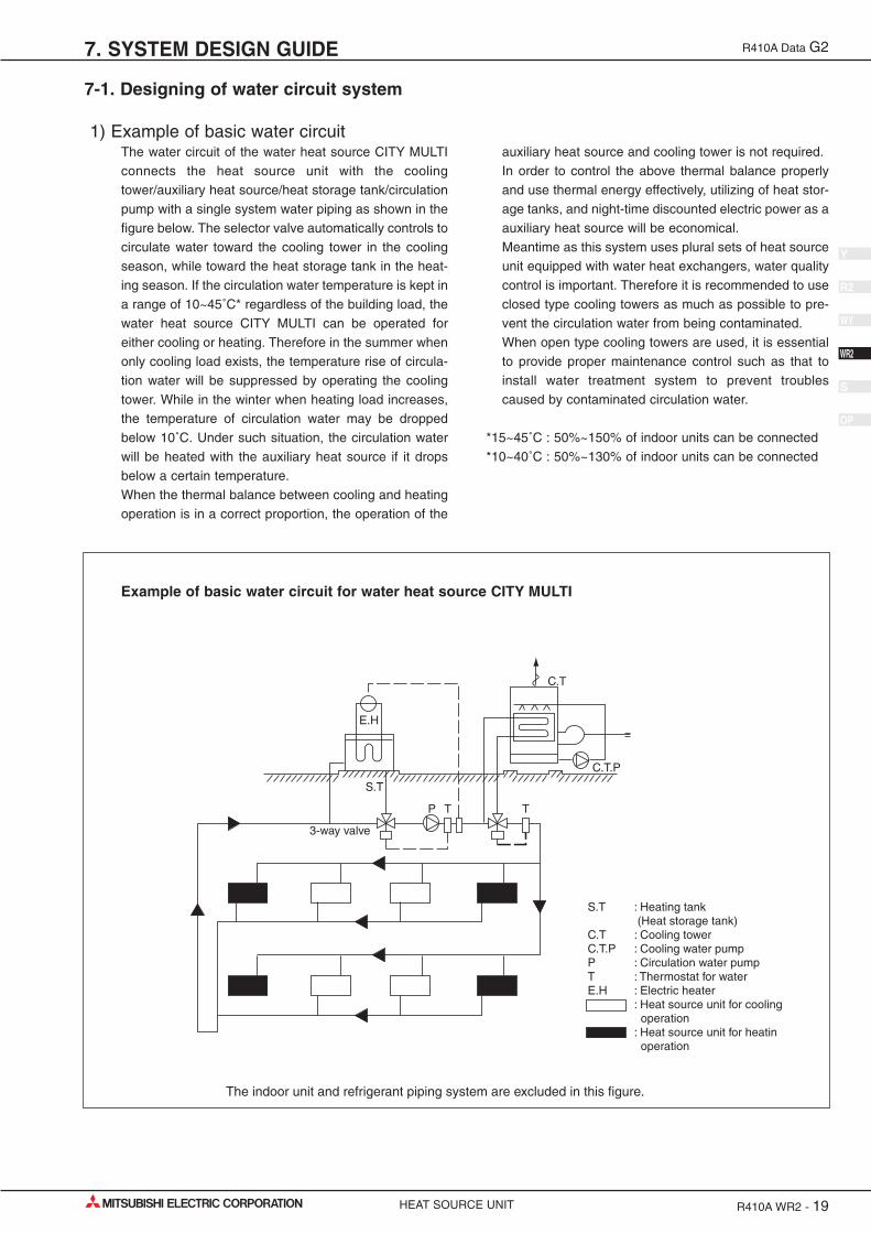
1) Example of basic water circuitThe water circuit of the water heat source CITY MULTI
connects the heat source unit with the cooling
tower/auxiliary heat source/heat storage tank/circulation
pump with a single system water piping as shown in the
figure below. The selector valve automatically controls to
circulate water toward the cooling tower in the cooling
season, while toward the heat storage tank in the heat-
ing season. If the circulation water temperature is kept in
a range of 10~45˚C* regardless of the building load, the
water heat source CITY MULTI can be operated for
either cooling or heating. Therefore in the summer when
only cooling load exists, the temperature rise of circula-
tion water will be suppressed by operating the cooling
tower. While in the winter when heating load increases,
the temperature of circulation water may be dropped
below 10˚C. Under such situation, the circulation water
will be heated with the auxiliary heat source if it drops
below a certain temperature.
When the thermal balance between cooling and heating
operation is in a correct proportion, the operation of the
auxiliary heat source and cooling tower is not required.
In order to control the above thermal balance properly
and use thermal energy effectively, utilizing of heat stor-
age tanks, and night-time discounted electric power as a
auxiliary heat source will be economical.
Meantime as this system uses plural sets of heat source
unit equipped with water heat exchangers, water quality
control is important. Therefore it is recommended to use
closed type cooling towers as much as possible to pre-
vent the circulation water from being contaminated.
When open type cooling towers are used, it is essential
to provide proper maintenance control such as that to
install water treatment system to prevent troubles
caused by contaminated circulation water.
*15~45˚C : 50%~150% of indoor units can be connected
*10~40˚C : 50%~130% of indoor units can be connected
E.H
S.T
T T
C.T.P
C.T
P
3-way valve
S.T : Heating tank (Heat storage tank) C.T : Cooling tower C.T.P : Cooling water pump P : Circulation water pump T : Thermostat for water E.H : Electric heater : Heat source unit for cooling operation : Heat source unit for heatin operation
The indoor unit and refrigerant piping system are excluded in this figure.
Example of basic water circuit for water heat source CITY MULTI

7. SYSTEM DESIGN GUIDE
HEAT SOURCE UNIT R410A WR2 - 20
R410A Data G2
Y
WY
R2
WR2
S
OP
2) Cooling towera) Types of cooling tower
The cooling towers presently used include the open type
cooling tower, open type cooling tower + heat exchang-
er, closed type cooling tower, and air-cooled type cooling
tower. However, as the quality control of circulation
water is essential when units are installed in decentral-
ized state inside a building, the closed type cooling
tower is generally employed in such case.
Although the circulation water will not be contaminated
by atmospheric air, it is recommended to periodically
blow water inside the system and replenish fresh water
instead.
In a district where the coil may be frozen in the winter, it
is necessary to apply antifreeze solution to the circula-
tion water, or take freeze protection measures such as to
automatically discharge water inside the cooling coil at
the stopping of the pump.
When the open type cooling tower is used, be sure to
install a water quality control device in addition to the
freeze protection measures, as the water may be deteri-
orated by atmospheric contaminants entered into the
cooling tower and dissolved into the circulation water.
b) Calculation method of cooling tower capacityAll units of the water heat source CITY MULTI may pos-
sibly be in cooling operation temporarily (at pulling
down) in the summer, however, it is not necessary to
determine the capacity according to the total cooling
capacity of all CITY MULTI units as this system has a
wide operating water temperature range
(15~45˚C : 130% over
10~45˚C : 130% or less ).
It is determined in accordance with the value obtained
by adding the maximum cooling load of an actual build-
ing, the input heat equivalent value of all CITY MULTI
units, and the cooling load of the circulating pumps.
Please check for the values of the cooling water volume
and circulation water volume.
Cooling tower capacity = (Refrigeration ton)
Qc : Maximum cooling load under actual state (kcal/h)Qw : Total input of water heat source CITY MULTI at simultaneous operation under
maximum state (kW)Pw : Shaft power of circulation pumps (kW)
Closed type
Air-cooled type
Types of cooling towers
Qc + 860 x (∑Qw + Pw)
3,900

QH = HCT ( 1 - ) - 1000 x Vw x ∆T - 860 x Pw
QH : Auxiliary heat source capacity (kcal/h)HCT : Total heating capacity of each water heat source CITY MULTI (kcal/h)COPH : COP of water heat source CITY MULTI at heatingVW : Holding water volume inside piping (m3)∆T : Allowable water temperature drop = TWH - TWL (˚C)TWH : Heat source water temperature at high temperature side (˚C)TWL : Heat source water temperature at low temperature side (˚C)PW : Heat source water pump shaft power (kW)
3) Auxiliary heat source and heat storage tankWhen the heating load is larger than the cooling load,
the circulation water temperature lowers in accordance
with the heat balance of the system. It should be heated
by the auxiliary heat source in order to keep the inlet
water temperature within the operating range
(15˚C or more : 130% over
10˚C or more : 130% or less )
of the water heat source CITY MULTI.
Further in order to operate the water heat source CITY
MULTI effectively, it is recommended to utilize the heat
storage tank to cover the warming up load in the morn-
ing and the insufficient heat amount.
Effective heat utilization can be expected to cover insuf-
ficient heat at the warming up in the next morning or
peak load time by storing heat by installing a heat stor-
age tank or operating a low load auxiliary heat source at
the stopping of the water heat source CITY MULTI. As it
can also be possible to reduce the running cost through
the heat storage by using the discounted night-time elec-
tric power, using both auxiliary heat source and heat
storage tank together is recommended.
The effective temperature difference of an ordinary heat
storage tank shows about 5deg. even with the storing
temperature at 45˚C.
However with the water heat source CITY MULTI, it can
be utilized as heating heat source up to 15˚C with an
effective temperature of a high 30deg. approximately,
thus the capacity of the heat storage tank can be mini-
mized.
a)Auxiliary heat sourceThe following can be used as the auxiliary heat source.
• Boiler (Heavy oil, kerosine, gas, electricity)
• Electric heat (Insertion of electric heater into heat stor-
age tank)
• Outdoor air (Air-heat source heat pump chiller)
• Warm discharge water (Exhaust water heat from
machines inside building and hot water supply)
• Utilization of night-time lighting
•Solar heat
Please note that the auxiliary heat source should be
selected after studying your operating environment and
economical feasibility.
Determining the auxiliary heat source capacity
For the CITY MULTI water heat source system, a heat
storage tank is recommended to use. When employment
of the heat storage tank is difficult, the warming up oper-
ation should be arranged to cover the starting up heat-
ing load. Since the holding water inside the piping circuit
owns heat capacity and the warming up operation can
be assumed for about one hour except that in a cold
region, the heat storage tank capacity is required to be
that at the maximum daily heating load including the
warming up load at the next morning of the holiday.
However the auxiliary heat source capacity should be
determined by the daily heating load including warming
up load on the week day.
For the load at the next morning of the holiday, heat stor-
age is required by operating the auxiliary heat source
even outside of the ordinary working hour.
1
COPh
When heat storage tank is not used
7. SYSTEM DESIGN GUIDE
HEAT SOURCE UNIT R410A WR2 - 21
R410A Data G2
Y
WY
R2
WR2
S
OP

7. SYSTEM DESIGN GUIDE
HEAT SOURCE UNIT R410A WR2 - 22
R410A Data G2
Y
WY
R2
WR2
S
OP
HQ1T = ( 1 - ) - 860 x Pw x T2
QH = x K (Kcal)T1
QH1T : Total of heating load on weekday including warming up (kcal/day)T1 : Operating hour of auxiliary heat source (h)T2 : Operating hour of heat source water pump (h)K : Allowance factor (Heat storage tank, piping loss, etc.) 1.05~1.10
HQ1T is calculated from the result of steady state load calculation similarly by using the equation below.HQ1T = 1.15 x (∑Q'a + ∑Q'b + ∑Q'c + ∑Q'd + ∑Q'f) T2 - ψ (∑Qe1 + ∑Qe2 + ∑Qe3) (T2 - 1)
Q'a : Thermal load from external wall/roof in each zone (kcal/h)Q'b : Thermal load from glass window in each zone (kcal/h)Q'c : Thermal load from partition/ceiling/floor in each zone (kcal/h)Q'd : Thermal load by infiltration in each zone (kcal/h)Q'f : Fresh outdoor air load in each zone (kcal/h)Q'e1 : Thermal load from human body in each zone (kcal/h)Q'e2 : Thermal load from lighting fixture in each zone (kcal/h)Q'e3 : Thermal load from equipment in each zone (kcal/h)ψ : Radiation load rate 0.6~0.8T2 : Air conditioning hour
1
COPh
When heat storage tank is used;
b) Heat storage tankHeat storage tank can be classified by types into the
open type heat storage tank exposed to atmosphere,
and the closed type heat storage tank with structure sep-
arated from atmosphere. Although the size of the tank
and its installation place should be taken into account,
the closed type tank is being usually employed by con-
sidering corrosion problems.
The capacity of heat storage tanks is determined in
accordance with the daily maximum heating load that
includes warming up load to be applied for the day after
the holiday.
HQ2T ( 1 - ) - 860 x Pw x T2 - QH x T2
V = (ton)∆T x 1000 x ηV
HQ2T ( 1 - ) - 860 x Pw x T2
V = (ton)∆T x 1000 x ηV
HQ2T : Maximum heating load including load required for the day after the holiday (kcal/day)∆T : Temperature difference utilized by heat storage tank (deg)ηV : Heat storage tank efficiency
HQ2T : 1.3 x (∑Q'a + ∑Q'c + ∑Q'd + ∑Q'f) T2 - ψ(∑Qe2 + ∑Qe3) (T2 - 1)
1
COPh
When auxiliary heat source is operated during operation and even after stopping of water heat source CITY MULTI unit
When auxiliary heat source is operated after stopping of water heat source CITY MULTI unit
1
COPh

4) Piping systemThe following items should be kept in your mind in plan-
ning / designing water circuits.
a) All units should be constituted in a single circuit in princi-
ple.
b) When plural numbers of the water heat source CITY
MULTI unit are installed, the rated circulating water flow
rate should be kept by making the piping resistance to
each unit almost same value. As an example, the
reverse return system as shown below may be
employed.
c) Depending on the structure of a building, the water circuit
may be prefabricated by making the layout uniform.
d) When a closed type piping circuit is constructed, install an
expansion tank usable commonly for a make-up water
tank to absorb the expansion/contraction of water
caused by temperature fluctuation.
e) If the operating temperature range of circulation water
stays within the temperature near the normal tempera-
ture (summer : 30˚C, winter : 20˚C), thermal insulation or
anti-sweating work is not required for the piping inside
buildings.
In case of the conditions below, however, thermal insu-
lation is required.
• When well water is used for heat source water.
• When piped to outdoor or a place where freezing may be
caused.
• When vapor condensation may be generated on piping
due to an increase in dry bulb temperature caused by
the entry of fresh outdoor air.
Heat source
unit
BC controller
Backflow prevention valvePump Strainer
3-way valve
3-way valve
Cooling tower Heating tank
Flexible joint
Refregerant piping
Refregerant piping
To indoor unit
ValveJoint
Drain
Y-shape strainer
Heat source
unit
BC controller
Heat source
unit
BC controller
Heat source
unit
BC controller
System example of water circuit
7. SYSTEM DESIGN GUIDE
HEAT SOURCE UNIT R410A WR2 - 23
R410A Data G2
Y
WY
R2
WR2
S
OP

R410A WR2 - 24
R410A Data G2
Y
WY
R2
WR2
S
OP
7. SYSTEM DESIGN GUIDE
HEAT SOURCE UNIT
5) Cleaning of water heat exchangerFor the water heat exchanger, scale adheres in less
amount generally in the case of closed type cooling tow-
ers. However in a long period of use, scale will adhere
that may lower the heat exchange capacity and increase
the water resistance.
In such case, conduct cleaning work under the proce-
dure given below.
The cleaning work procedure generally used is as fol-
lows. However as the cleaning agents have various dif-
ferences in their cleaning effect, corrosion characteris-
tics, processing time, and condensation for use, conduct
the work after consulting the relating maker.
Acid washing Water washing Neutralization Water washing Applying inhibitor
a)Still standing methodThis method feeds the raw liquid or diluted solution of
cleaning agent into the water circuit and leave it for a
while, and requires only a simple device.
• Since the cleaning time required differs by the agent of
each maker, be sufficiently careful for the time and not
to exceed the time specified.
• Fully recover the cleaning liquid through the water dis-
charge plug of the heat exchanger, and then fully clean
the water circuit with clean water. If the water washing
can not be made sufficiently, neutralization processing
will be effective.
Cleaning agent
Hose
To be closed
Water discharge plugT-joint : When no exclusive T-joint is available, use the connection of the thermometer or the like.
Still standing cleaning device

b)Circulation methodAlthough this method can clean in shorter time than that
required by the still standing method, be careful that the
circulation pump may be damaged if using cleaning
agent with strong corrosive characteristics.
• After completing washing work, fully recover the wash-
ing liquid through the water discharge plug installed at
the bottom of the piping and that at the heat exchanger.
• Conduct water washing for three times or more after
removing cleaning agent. If this can not be made satis-
factorily, apply neutralization treatment. Full replace-
ment of water can be ascertained by measuring the PH
of the water.
• Note that it may be required to control the cleaning time
depending on the scale generation or water quality.
• At cleaning work, remove or shut down the instruments
like water pressure gauges so that the cleaning liquid
will not enter into them.
• Check for the connections of piping beforehand so that
cleaning agent will not leak from the piping during
cleaning work.
• Start cleaning operation after fully mixing the cleaning
agent with water.
• Cleaning at the earlier timing is recommended as the
removal of scale will be difficult if it has accumulated
seriously. Periodical cleaning is necessary in a district
with inferior water quality.
• Conduct water washing sufficiently with clear water after
cleaning work as all cleaning agents own strong acidity.
• To verify the completion of cleaning, remove the hose
and observe the inner wall of the piping whether it is
clean.
• Be sufficiently careful for fire when using inflammable
cleaning agent (GOSPEL R).
Water discharge plugWater discharge plug
Filtration net
Cleaning agent
Tank
Hose
Hose
To be closed
To be closed
T-joint
T-joint
Pump
Circulation method cleaning device
Name
CLEARLITE RK
GOSPEL SR
ADDITION DR
SS-100
NEOLUX F
DISCALER
CLEARLITE ACE
GOSPEL R
Shape
Powder/Liquid
Powder
Powder
Liquid
Powder
Powder
Powder/Liquid
Liquid
Condensation
10~20%
Upper limit 10%, lower limit 5%
4~7%
3~5%
7%
Time
2~3Hr.
1~3Hr.
1~4Hr.
Makers
Koei Kagaku
Marusan
Seiwa kogyo
Saver Kagaku
Koei Kagaku
Gospel Kako
( )
Example of cleaning agents
7. SYSTEM DESIGN GUIDE
HEAT SOURCE UNIT R410A WR2 - 25
R410A Data G2
Y
WY
R2
WR2
S
OP

6) Practical System Examples and CirculationWater Control
Since the water heat source CITY MULTI is of water heat
source system, versatile systems can be constituted by
combining it with various heat sources.
The practical system examples are given below.
Either cooling or heating operation can be performed if
the circulation water temperature of the water heat
source CITY MULTI stays within a range of 15~45˚C.
However, the circulation water temperature near 32˚C
for cooling and 20˚C for heating is recommended by tak-
ing the life, power consumption and capacity of the air
conditioning units into consideration. The detail of the
control is also shown below.
Heat source
unit
Heat exchanger
Heat storage tank pump
T1~T4: Thermostat V1~V2: Proportional type motor-driven 3-way valve V3 : Motor-driven 3-way valve XS : Auxiliary switch MG : Magnetic switch EH : Electric heater
Heat storage tank
Auxiliary heat source
T2
V2
EH
T4
MG
V3
T3
Cooling water pumpClosed type cooling tower
Expansion tank
Circulation water pump
V1
T1XS
Example-1 Combination of closed type cooling tower and hot water heat storage tank (using underground hollow slab)
By detecting the circulation water temperature of the water heat source CITY MULTI system with T1 (around 32˚C) and
T2 (around 20˚C), the temperature will be controlled by opening/closing V1 in the summer and V2 in the winter.
In the summer, as the circulation water temperature rises exceeding the set temperature of T1, the bypass port of V1 will
open to lower the circulation water temperature. While in the winter, as the circulation water temperature drops, V2 will
open following the command of T2 to rise the circulation water temperature.
The water inside the heat storage tank will be heated by the auxiliary heat source by V3 being opened with timer opera-
tion in the night-time. The electric heater of the auxiliary heat source will be controlled by T3 and the timer. The start/stop
control of the fan and pump of the closed type cooling tower is applied with the step control of the fan and pump follow-
ing the command of the auxiliary switch XS of V1, that operates only the fan at the light load while the fan and pump at
the maximum load thus controlling water temperature and saving motor power.
7. SYSTEM DESIGN GUIDE
HEAT SOURCE UNIT R410A WR2 - 26
R410A Data G2
Y
WY
R2
WR2
S
OP

7. SYSTEM DESIGN GUIDE
HEAT SOURCE UNIT R410A WR2 - 27
R410A Data G2
Y
WY
R2
WR2
S
OP
Heat source
unit
Closed type cooling tower
T1 : Proportional type, insertion system thermostat T2 : Proportional type, insertion system thermostat T3 : Proportional type, insertion system thermostat V1 : Proportional type, motor-driven 3-way valve V2 : Proportional type, motor-driven 3-way valve XS : Auxiliary switch (Duplex switch type) SC : Step controller R : Relay MG: Magnetic
SC MG
T3
CV
V1
XS
R
V2
T2
Hot water heat storage tank
Heat source water pumpPump interlock
Example-2 Combination of closed type cooling tower and hot water heat storage tank
In the summer, as the circulation water temperature rises exceeding the set temperature of T1, the bypass port of V1 will
open to lower the circulation water temperature. In the winter, if the circulation water temperature stays below 25˚C, V2
will open/close by the command of T2 to keep the circulation water temperature constant.
The temperature of the hot water inside the heat storage tank will be controlled through the step control of the electric
heater by step controller operation following the command of T3.
During the stopping of the heat source water pump, the bypass port of V2 will be closed fully by interlocking thus pre-
venting the high temperature water from entering into the system at the starting of the pump.
The start/stop control of the fan and pump of the closed type cooling tower is applied with the step control of the fan and
pump following the command of the auxiliary switch XS of V1, that operates only the fan at the light load while the fan
and pump at the maximum load thus controlling water temperature and saving motor power.

7. SYSTEM DESIGN GUIDE
HEAT SOURCE UNIT R410A WR2 - 28
R410A Data G2
Y
WY
R2
WR2
S
OP
Heat source
unit
Closed type cooling tower
T1 : Proportional type, insertion system thermostat T2 : Proportional type, insertion system thermostat T3 : Proportional type, insertion system thermostat V1 : Proportional type, motor-driven 3-way valve S : Selector switch R : Relay XS : Auxiliary switch (Duplex switch type)
Relay board
Boiler
XSV1
T1
V2
R
T2
Heat source water pump
Pump interlock
Example-3 Combination of closed type cooling tower and boiler
In the summer, as the circulation water temperature rises exceeding the set temperature of T1, the bypass port of V1 will
close to lower the circulation water temperature. In the winter, if the circulation water temperature drops below 25˚C, V2 will
conduct water temperature control to keep the circulation water temperature constant.
During the stopping of the heat source water pump, the bypass port of V2 will be closed fully by interlocking.
The start/stop control of the fan and pump of the closed type cooling tower is applied with the step control following the com-
mand of the auxiliary switch XS of V1, thus controlling water temperature and saving motor power.

7. SYSTEM DESIGN GUIDE
HEAT SOURCE UNIT R410A WR2 - 29
R410A Data G2
Y
WY
R2
WR2
S
OP
Heat source
unit
Closed type cooling tower
T1 : Proportional type, insertion system thermostat T2 : Proportional type, insertion system thermostat V1 : Proportional type, motor-driven 3-way valve V2 : Proportional type, motor-driven 3-way valve S : Selector switch R : Relay XS : Auxiliary switch (Duplex switch type)
Relay board
XSV1
T1
V2
T2
Heat source water pump
Heat exchanger
Other heat source water
Example-4 Combination of closed type cooling tower and heat exchanger (of other heat source)
In the summer, as the circulation water temperature rises exceeding the set temperature of T1, the bypass port of V1 will
close to lower the circulation water temperature. In the winter, if the circulation water temperature drops below 26˚C, V2
will conduct water temperature control to keep the circulation water temperature constant.
During the stopping of the heat source water pump, the bypass port of V2 will be closed fully by interlocking.
The start/stop control of the fan and pump of the closed type cooling tower is applied with the step control following the
command of the auxiliary switch XS of V1, thus controlling water temperature and saving motor power.
7. SYSTEM DESIGN GUIDE
HEAT SOURCE UNIT R410A WR2 - 30
R410A Data G2
Y
WY
R2
WR2
S
OP
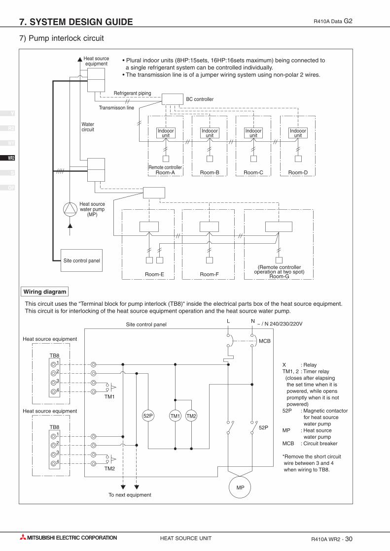
7) Pump interlock circuit
Indooor unit
Heat source equipment
Water circuit
Heat source water pump
(MP)
Site control panel
Refrigerant piping
Transmisson line
BC controller
Remote controller Room-A
Indooor unit
Room-B
Room-E
Indooor unit
Room-C
Indooor unit
Room-D
Room-F(Remote controller
operation at two spot) Room-G
TM1
TM2
1
TB8
Heat source equipment
Heat source equipment
To next equipment
2
3
4
1
TB8
2
3
4
52P
MP
Site control panel ~ / N 240/230/220V
X : Relay TM1, 2 : Timer relay (closes after elapsing the set time when it is powered, while opens promptly when it is not powered) 52P : Magnetic contactor for heat source water pump MP : Heat source water pump MCB : Circuit breaker *Remove the short circuit wire between 3 and 4 when wiring to TB8.
52P
TM1
MCB
TM2
• Plural indoor units (8HP:15sets, 16HP:16sets maximum) being connected to a single refrigerant system can be controlled individually. • The transmission line is of a jumper wiring system using non-polar 2 wires.
This circuit uses the “Terminal block for pump interlock (TB8)“ inside the electrical parts box of the heat source equipment. This circuit is for interlocking of the heat source equipment operation and the heat source water pump.
Wiring diagram
L N

7. SYSTEM DESIGN GUIDE
HEAT SOURCE UNIT R410A WR2 - 31
R410A Data G2
Y
WY
R2
WR2
S
OP
Operation ON signal
Pump Interlock
Terminal No.
Output
Operation
TB8-1, 2
Relay contacts output Rated voltage : L1 - N : 220 ~ 240VRated load : 1A
• When Dip switch 2-7 is OFF The relay closes during compressor operation.
• When DIP switch 2-7 is ON. The relay closes during reception of cooling or the heating operation signal from the controller. (Note : It is output even if the thermostat is OFF (when the compressor is stopped).)
Terminal No.
Input
Operation
TB8-3, 4
Level signal
If the circuit between TB8-3 and TB8-4 is open, compressor operation is prohibited.

7. SYSTEM DESIGN GUIDE
HEAT SOURCE UNIT R410A WR2 - 32
R410A Data G2
Y
WY
R2
WR2
S
OP
1) Items to be observed on installation work• In order to equalize piping resistance for each unit, adapt
the reverse return system.
• Mount a joint and a valve onto the water outlet/inlet of the
unit to allow for maintenance, inspection and replace-
ment work. Be sure to mount a strainer at the water inlet
piping of the unit. (The strainer is required at the circula-
tion water inlet to protect the heat source unit.)
* The installation example of the heat source unit is shown
right.
• Be sure to provide an air relief opening on the water pip-
ing properly, and purge air after feeding water to the pip-
ing system.
• Condensate will generate at the low temperature part
inside the heat source equipment. Connect drain piping
to the drain piping connection located at the bottom of
the heat source equipment to discharge it outside the
equipment.
• At the center of the header of the heat exchanger water
inlet inside the unit, a plug for water discharge is being
provided.
Use it for maintenance work or the like.
• Mount a backflow prevention valve and a flexible joint for
vibration control onto the pump.
• Provide a sleeve to the penetrating parts of the wall to
prevent the piping.
• Fasten the piping with metal fitting, arrange the piping
not to expose to cutting or bending force, and pay suffi-
cient care for possible vibration.
• Be careful not to erroneously judge the position of the
inlet and outlet of water.
(Lower position : Inlet, Upper position : Outlet)
2) Thermal insulation workThermal insulation or antisweating work is not required
for the piping inside buildings in the case of the CITY
MULTI WR2 system if the operating temperature range
of circulation water stays within the temperature near the
normal (summer : 30˚C, winter : 20˚C).
In case of the conditions below, however, thermal insu-
lation is required.
• Use of well water for heat source water
• Outdoor piping portions
• Indoor piping portions where freezing may be caused in
winter
• A place where vapor condensation may be generated on
piping due to an increase in dry bulb temperature inside
the ceiling caused by the entry of fresh outdoor air
• Drain piping portions
3) Water treatment and water quality controlFor the circulation water cooling tower of the CITY
MULTI WR2 system, employment of the closed type is
recommended to keep water quality. However, in the
case that an open type cooling tower is employed or the
circulating water quality is inferior, scale will adhere onto
the water heat exchanger leading to the decreased heat
exchange capacity or the corrosion of the heat exchang-
er. Be sufficiently careful for water quality control and
water treatment at the installation of the circulation water
system.
• Removal of impurities inside piping
Be careful not to allow impurities such as welding frag-
ment, remaining sealing material and rust from mixing
into the piping during installation work.
• Water treatment
The water quality standards have been established by
the industry (Japan Refrigeration, Air Conditioning
Industry Association, in case of Japan) for water treat-
ment to be applied.
7-2.WATER PIPING WORKAlthough the water piping for the CITY MULTI WR2 system does not differ from that for ordinary air condition-ing systems, pay special attention to the items below in conducting the piping work.
Water circulation pipe
Close valve
Close valve
Water outlet
Refrigerant piping
Y-type strainer
Water inlet
Drain pipeDrain pipe
Sub unit(Heatexchanger)
Compressor unit
Installation example of heat source unit
pH (25˚C)Electric conductivity (mS/m) (25˚C)
( µ s/cm) (25˚C)Chloride ion (mg Cl-/ )Sulfate ion (mg SO42-/ )Acid consumption (pH4.8)
(mg CaCO3/ )Total hardness (mg CaCO3/ )Calcium hardness (mg CaCO3/ )Ionic silica (mg SiO2/ )Iron (mg Fe/ )Copper (mg Cu/ )
Sulfide ion (mg S2-/ )
Ammonium ion (mg NH4+/ )
Residual chlorine (mg Cl/ )Free carbon dioxide (mg CO2/ )Ryzner stability index
Standarditems
Refer-enceitems
Items
Lower mid-rangetemperature water system
7.0 ~ 8.030 or less
[300 or less]50 or less50 or less
50 or less
70 or less50 or less30 or less1.0 or less1.0 or lessnot to bedetected
0.3 or less0.25 or less0.4 or less
–
7.0 ~ 8.030 or less
[300 or less]50 or less50 or less
50 or less
70 or less50 or less30 or less0.3 or less0.1 or lessnot to bedetected
0.1 or less0.3 or less4.0 or less
–
TendencyRecirculating
water[20<T<60˚C]
Make-upwater Corrosive
Scale-forming
Reference : Guideline of Water Quality for Refrigeration and Air ConditioningEquipment. (JRA GL02E-1994)

7. SYSTEM DESIGN GUIDE
HEAT SOURCE UNIT R410A WR2 - 33
R410A Data G2
Y
WY
R2
WR2
S
OP
In order to keep the water quality within such standards,
you are kindly requested to conduct bleeding-off by
overflow and periodical water quality tests, and use
inhibitors to suppress condensation or corrosion. Since
piping may be corroded by some kinds of inhibitor, con-
sult an appropriate water treatment expert for proper
water treatment.
(4) Pump interlockOperating the heat source unit without circulation water
inside the water piping can cause a trouble. Be sure to
provide interlocking for the unit operation and water cir-
cuit. Since the terminal block is being provided inside the
unit, use it as required.

HEAT SOURCE UNIT R410A WR2 - 34
R410A Data G2
Y
WY
R2
WR2
S
OP
![SUPPLEMENTARY INFORMATION · 2010-04-23 · Final R indices [I>2sigma(I)] R1 = 0.0593, wR2 = 0.1165 R indices (all data) R1 = 0.1209, wR2 = 0.1364 Extinction coefficient 0.00009(8)](https://static.fdocuments.us/doc/165x107/5f6e491b7d1bc05a47690ca3/supplementary-information-2010-04-23-final-r-indices-i2sigmai-r1-00593.jpg)


![Aryl-substituted boron subphthalocyanines and their ... · Final R indices [I>2sigma(I)] R1 = 0.0326, wR2 = 0.0823 R indices (all data) R1 = 0.0375, wR2 = 0.0863 Largest difference](https://static.fdocuments.us/doc/165x107/5f6e4aa914926b165d485e35/aryl-substituted-boron-subphthalocyanines-and-their-final-r-indices-i2sigmai.jpg)