V Unit Customized Part
124
1 Wireless Systems and standards
-
Upload
sameer-salam -
Category
Documents
-
view
215 -
download
1
Transcript of V Unit Customized Part

1
Wireless Systems and standards

2
Standard setting bodies in Wireless
• ITU-T• IEEE for Wireless LANs (802 committee)
– Examples are: IEEE802.11, IEEE 802.15, IEEE 802.16• European Telecommunications Standards Institute
(ETSI): GSM• EIC: Electronic Industry Association:
– Examples: Interim std IS-54, IS-136 (TDMA in 800-900 and 1900 Mhz band)
• TIA: telecommunication Industry Association IS-95 CDMA
• Cellular Telecommunications and Internet Association (CTIA)
• The Open Mobile Alliance (OMA),

3
Cellular technologies evolution
• Broadly classified as – First generation– Second generation– Two and half (2.5 G) generation– Third generation– Already talking about 4 and th generation

4
Cellular Technologies Evolution Cont’d• First generation cellular systems (analog)
– Advanced Mobile phone service (AMPS)(1983)• Frequency band: 824-894 MHz, channel BW of 30 KHz, FM
modulation • Frequency division multi access• Mobility to the phone service
– Narrow Band Advanced Mobile phone service (NAMPS)(1992)• Same as AMPS, except uses channel BW of 10 KHz
– Total Access Cellular system (Mostly in Europe) 1985• Frequency band: 900 MHz, channel BW of 25 KHz, FM modulation • Frequency division multi access• Also called European Total Access Cellular System
– Nordic Mobile telephone system • Frequency band: 450-470 MHz, channel BW of 25 KHz, FM
modulation Developed in 1981. Uses FDMA• Freq band: 890-960 MHz, channel bandwidth of 12.5 KHz FM
modulation Developed in 19861. Uses FDMA

5
Cellular Evolution (Cont’d)• 2nd generation Cellular system (Digital)
– Global System for Mobile Comm. (GSM) 1990• Frequency band: 890-960 MHz• Channel bandwidth of 200 KHz• Uses Time division multiple access (TDMA)- 8 TDM channels on one
freq carrier• Modulation : GMSK (Gaussian Minimum shift keying)
– United states Digital cellular (USDC): IS-54/IS136 (also known as digital AMPS) 1990
• IS-54 and IS-136 are standards for TDMA American Digital Cellular.• Frequency band: 824-894 MHz, and 1.8/1.9 GHz• Multiple access method (TDMA/FDM)• Channel Spacing: 30Khz
– Supports 3 time slots • Modulation: DQPSK (Differential Quadrature phase shift keying)• Channel Bit Rate: 48.6Kb• Used in USA, South America and Australia
6
Cellular Evolution (Cont’d)
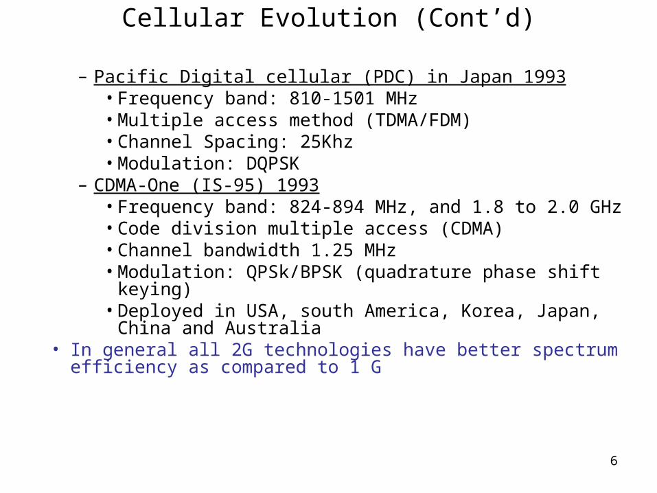
– Pacific Digital cellular (PDC) in Japan 1993• Frequency band: 810-1501 MHz• Multiple access method (TDMA/FDM)• Channel Spacing: 25Khz• Modulation: DQPSK
– CDMA-One (IS-95) 1993• Frequency band: 824-894 MHz, and 1.8 to 2.0 GHz• Code division multiple access (CDMA)• Channel bandwidth 1.25 MHz• Modulation: QPSk/BPSK (quadrature phase shift keying)• Deployed in USA, south America, Korea, Japan, China
and Australia• In general all 2G technologies have better spectrum efficiency
as compared to 1 G

7
2nd generation Technology

8
AMPS AMPS (Advanced Mobile cellular system)
• Uses 800 Mhz band • First implemented in Chicago to cover approximately 2100 square
miles– Used large cells and omni directional antennas to minimize equipment
needs
• The AMPS system uses 7 cell reuse pattern with provision for sectoring and cell splitting to increase capacity when required.
• Smallest reuse factor that satisfies this condition with 120 degrees sectoring is 7 cell reuse.

9
AMPS
• In US each provider ( A and B) used 416 duplex channels each.
• The freq allocations vary from country to country
• The Air Interface standard is identical thru the world.
• Each system has System ID (SID). Provider A has been assigend odd SID numbers while provider B is assigend even SID numbers

10
AMPS overview• Uses FDMA/FDD for Radio transmission
• Reverse link: 824 to 849 Mhz• Forward link: 869 to 894 Mhz• Channel assignment ; 30 Khz
• Separation of 45 Mhz between forward and reverse channel. – This allows use of inexpensive, but highly selective duplexers in the
subscriber units• Max freq deviation +- 12 Khz (+- 10 Khz for ETACS)
• The Base stations have tall towers, supporting several receiving antennas, and have TX antennas that radiate a few hundred watts of effective radiated power
• Each Cell typically has one control channel transmitter, that broadcasts on this channel

11
AMPS overview (cont’d)• Each cell has one control channel receiver
– This reverse channel is used for call set up.
• Each cell also supports 8 or more duplex channels
• Commercial base stations support as many as 57 duplex channels
• Actual number of Voice channels and control channels per cell varies from implementation to implementation – Depending upon offered traffic, maturity of the system and
locations of other base stations
• Actual number of base stations also varies.– In a rural area there may be only one cell tower– In urban areas there may be several hundred base stations

12
AMPS Overview (Cont’d)
• In each US Market the “ A” provider is assigned an odd system Identification number (SIN), while “B” provider is assigned an even system Identification number (SIN),
• SIN is transmitted every 0.8 secs, on each FCC, along with other data such as – status of the cellular system.– If roamers will be automatically registered– How power control is handled– if other standards such as N-AMPS or USDC can be
supported by the system• In US mobile subscribers either access system “A” or “B”, even
though technically the subscribers can access both. • Each System “A” or “ B” supports 416 channels, out of which 21
are uses as control channels

13
AMPS : Types of Channels• Control channels
– Reverse and forward control channels• Control channels are used for call set up• Registration • Paging ( Notification of an incoming call to a mobile)
• Voice channels (Reverse and forward control channels)– Voice signals– Supervisory audio tone (SAT)– Signaling tone (Used for sending a signal from a mobile
indicating call termination)– Blank and burst ( The voice transmission is suspended, and data
is sent may be to effect a hand-off)

14
ETACS overview• Uses FDMA/FDD for Radio transmission• Reverse link: 890 to 915 MHz• Forward link: 935 to 960 MHz• Total number of channels supported : 1000• Max freq deviation +- 10 KHz• The control channel TX and Blank and burst transmission are at 8
Kbps – These data streams have max freq. deviation of +- 6.4 KHz
• ETACS supports 42 control channels. ( Since no duopoly)• ETACS uses area identification numbers instead of SIN• ETACS users can access any control or voice channel.

15
Call Handling in AMPS/ETACS• Mobile registration process• When a mobile is powered on it runs a self diagnostic. Then it starts to scan
the forward control channels. It picks the cell with strongest signal. Mobile scans every 7 secs, or when signal strength falls below a certain threshold.
• Once it picks the strongest signal, it decodes SIN to determine if it is at its home location.
• If too many errors it will pick next strongest signal
• When MS has successfully camped on to a FCC it transmits a message which contains info such as Electronic serial number (ESN), its phone number, its home system ID etc. The mobile sends this info in the RCC.
• The base station sends this information to MSC, which consults with various databases to check the info out.
• If everything checks out the mobile is ready to either make a call or receive a call
For blank and burst mode data transmission, FSK is used by both the base and mobile station in blank and burst mode to initiate handoff, to change the subscriber power , and provide other system data.

16
Call Handling in AMPS/ETACS (Cont’d)Mobile receiving an incoming call• Mobile continues to monitor control channel.• If there is an incoming call for this mobile, a page is sent by MSC on all the base station’s
FCCs. The page includes the mobiles MIN. • If the intended mobile receives this page, it will send an ack on the RCC. • When MSC receives the ack, the MSC directs the base station to assign FVC and RVC to the
call.. • The base station also assigns to the subscriber unit a supervisory Audio tone (SAT), and
voice mobile attenuation code (VMAC)• After the RVC and FVC assignment the mobile moves to these new frequencies, and voice
transmission can proceed. Also during a call, if any signaling is required it is done on the pair of voice channels
• The SAT is transmitted continuously on both the FVC and RFC. • The VMAC instructs the mobile to transmit at a particular power level. • Once a call is up on a voice channel, all signaling is done on the voice channel via a scheme
known as "Blank and Burst". When the site needs to send an order to the mobile, such as hand off, power up, or power down, it mutes the SAT on the voice channel. This is filtered at the mobile so that the customer never hears it. When the SAT is muted, the phone mutes the audio path, thus the "blank", and the site sends a "burst" of data. The process takes a fraction of a second and is scarcely noticeable to the customer. Again, it's more noticeable on a Motorola system than on Ericsson or Lucent. You can sometimes hear the 'bzzt' of the data burst."

17
Telephone Call Made to A Mobile User
MSCMSC
Incoming Telephone call
2 65 4
3 7MS X
Step 1
BS
BSStep 1 – The incoming telephone call to Mobile X is received at the MSC.Step 2 – The MSC dispatches the request to all base stations in the cellular system.Step 3 – All the base stations broadcast the Mobile Identification Number (MIN), telephone number of Mobile X, as a paging message over the FCC throughout the cellular system.Step 4 – The mobile receives the paging message sent by the base station it monitors and responds by identifying itself over the reverse control channel (RCC).Step 5 – The base station relays the acknowledgement sent by the mobile and informs the MSC of the handshake.Step 6 – The MSC instructs the base station to move the call to an available voice channel within the cellStep 7 – The base station signals the mobile to change frequencies to an unused forward and reverse voice channel pair. .(Sends SAT, Voice mobile attenuation code)
and At the point another data message (alert) is transmitted over the forward voice channel (FVC) to instruct the mobile to ring.Now the call is established and conversion can proceed)
2
PSTN

18
Call Handling in AMPS/ETACS (Cont’d)Mobile initiating a call• When a subscriber unit initiates a call, the mobile unit sends an originating message
on RCC.– The originating message includes
• Subscriber MIN, ESN, station class mark and the destination telephone number
• The station class mark or SCM tells the cell site and the switch what power level the mobile phone operates at. The cell site can turn down the power in your phone, lowering it to a level that will do the job while not interfering with the rest of the system. In years past the station class mark also told the switch not to assign older phones to a so called expanded channel, since those phones were not built with the new frequencies the FCC allowed.
– If received correctly at the base station it sends this info to MSC• MSC checks out the information to determine if the subscriber is a registered
user, • Connects the subscriber to PSTN• Assigns the call to FVC and RFC, with specific SAT and VMAC
– This info is sent to the subscriber units, who switches to the new freq pair, adjusts it TX power level and returns the SAT back.
– During the call MSC will issue a number of blank and burst commands

19
Call Handling in AMPS/ETACS (Cont’d)
• Step 1 – When a mobile originates a call, it sends the base station its telephone number (MIN), electronic serial number (ESN), and telephone number of called party. It also transmits a station class mark (SCM) which indicates what the maximum power level is for the particular user.
• Step 2 – The cell base station receives the data and sends it to the MSC.• Step 3 – The MSC validates the request, makes connection to the called
party through the PSTN and instructs the base station and mobile user to move to an unused forward and reverse channel pair to allow the conversation to begin.
PSTNPSTN MSCMSC
2211
33Telephone callOriginated by a mobile
Mobile initiating a call

20
Call Handling in AMPS/ETACS (Cont’d)
• What happens when all the voice channels are busy?– The MSC will hold PSTN line open, and instructs the current
base station to issue a directed retry to the subscriber on FCC.– A directed retry forces the MS to switch to a different base
station, fro voice channel assignment– Depending on propagation conditions, location of a subscriber
unit and the current traffic in the base station the directed retry may or may not work.

21
Call Handling in AMPS/ETACS (Cont’d)• While voice channels are in use, three additional signaling
techniques are used– The supervisory signal audio tone (SAT); it always exists during voice
traffic except blank and burst – The signaling tone (ST)– Blank and burst wide band data (allow the adjustment of power levels, or
initiate a hyandoff)• The signaling tone (ST)
– Is a 10Kbps data burst, which signal call termination by the subscriber. – It is a special end-of call message consisting of “1” and “0”, which is sent
on RVC by a mobile for 200 ms. – Unlike blank and burst messages, which suspend the SAT transmission,
the ST tone has to be sent simultaneously with the SAT. – ST alerts the base station that the subscriber has ended the call.– When a user terminates a call, ST tone is automatically sent by the
mobile unit. – This lets the BS and MSC know that a call was terminated voluntarily by
the user, as opposed to being dropped by the system

22
supervisory Audio tone (SAT)• The purpose of SAT is indicate the continuity of the conversation• A SAT is a high pitched, inaudible tone that helps the system distinguish between callers
on the same channel but in different cells. .
• The detection of SAT must be performed every 250 msecs by the subscriber units
• The dropped or prematurely terminated calls are often traced to incorrect detection of SAT, or interference at the mobile
A given base station will always constantly transmit one of the 3 SAT tones on each voice channel while it is in use.
The particular freq of a SAT denotes a particular base station location for a given channel and is assigned by MSC for each call.

23
supervisory Audio tone (SAT) (Cont’d)
Example of SAT assignmentWithin a cluster of N=7
S0
S1
S2
S1
S1
S2
S2 S0
S1
S2
S1
S1
S2
S2
S0S1 S2
S1 S0 S2
S0 S0
S1
S0S0
S2

24
Radio Interface

25
USDC (IS-54 and IS-136)• IS-54 is the standard for the digital version of the US AMPS system.
• IS-54 has been replaced by the IS-136 standard.
• The system uses hybrid Frequency Division Multiple Access and Time Division Multiple Access concept as it accepts 3 users per carrier.
• The carrier spacing 30 kHz, similar to the analog AMPS. – Thus, assuming that the analog and digital system use the same frequency
reuse pattern, the digital version can accommodate three times more users.
• In terms of frequency planning the digital system behaves similar to analog AMPS.
• The USDC system was designed to use same frequency spectrum as AMPS, freq reuse plan, and base station. If the subscriber equipment and base station is eqiupped with both the AMPS channels and Digital channels then the AMPS system can be migrated to USDC in a graceful manner
• IS-136: IS-136 added a number of features to the original IS-54 specification, including text messaging, circuit switched data (CSD), and an improved compression protocol. SMS and CSD were both available as part of the GSM protocol, and IS-136 implemented them in a nearly identical fashion.

26
USDC Radio Interface• To ensure smooth migration from AMPS to USDC the IS-136 is
specified to operate in a dual mode, which makes roaming possible with a single phone
• USDC supports 3 subscribers in a single FVC/RVC channel• USDC uses TDMA. as more efficient voice coding becomes
available, it could potentially support more subscribers

27
USDC Radio Interface

28
USDC ChannelsSupervisory/control channel
– AMPS specifies 42 control channels ( 21 each for provider A and provider B)
– IS-136 has specified additional 42 called secondary control channels– The secondary control channels during transition can be allocated to
USDC only, so AMPS does not have to monitor or decode these channels, and the SMS and paging services may be introduced for USDC only
– After the transition is complete all the control channels will be used, to carry the signaling, paging and SMS traffic
• Voice channels: Same as AMPS except converted to TDMA. Occupies 30 Khz bandwidth in forward as well as in reverse direction. Each Voice channel supports a max of 3 users, and has six time slots. – For full rate speech coding a max of 3 users– For half rate speech coding a max of 6 users– User 1, may occupy slots 1 and 4, user 2 may occupy 3 and 5 slots,
while user 3 may occupy 3 and 6 time slots– A half rate user occupies only one slot

29
Full rate Voice channels
• A full rate traffic channel uses 2 time slots• A mobile typically uses idle time to measure the signal
strength of the surrounding channels to assist in MAHO

30
GSM Network Areas • Network Areas
– cells, – location areas (LAs), – MSC/VLR service areas, – public land mobile network (PLMN) areas.
• Cell:– Area covered by one BTS
• each cell is identified via the cell global identity (CGI) number assigned to each cell.
• Location Areas– The location area is a group of cells. – It is the area in which the subscriber is paged. – Each LA is served by one or more base station controllers, – yet only by a single MSC – Each LA is assigned a location area identity (LAI) number.

31
Location Area
– The location area is a group of cells. – It is the area in which the subscriber is paged. – Each LA is served by one or more base station controllers, – yet only by a single MSC – Each LA is assigned a location area identity (LAI) number.
Location Areas

32
MSC/VLR Service Areas
• An MSC/VLR service area represents the part of the GSM network
• covered by one MSC. • Each mobile is registered either in HLR, or in one VLR
MSC/VLR Service Areas

33
Public Land Mobile network Area
• The PLMN service area is an area served by one network operator

34
Interfaces used in GSM
MS to BTS interface: Air InterfaceComprises of speech channels andControl channels

35
Interfaces used in GSM (Cont’d)
• Mobile to base station interface (Um/air interface): Mobile Station and the Base Station Subsystem communicate across this interface. Also called radio link
– Standradized by GSM
• BTS to BSC interface (Abis interface): BTS and BSC communicate over this interface. Abis interface carries traffic and maintenance data
– Standardized by GSM– In reality, Abis interface for each manufacturer has subtle differences, hence forcing
carriers to use same vendor.
• BSC to MSC interface ( A interface); A BSC is connected to MSC via dedicated/leased line or microwave
– Standardized within GSM– A interface that supports both the communication between BSC and MSC – and network messages between mobile and MSC– The standardization permits a carrier to use BSC and MSC equipment from different
vendors

36
GSM Radio SubsystemGSM is operated in many radio bands.• Initially it used 2 (two) 25 Mhz bands
– 890-915 MHz for subscriber to base station (reverse )– 935-960 Mhz from base to subscriber (forward)– Each forward and reverse band divide into 200 KHz wide channels (called
Absolute Radio Freq Channel numbers)– The ARFCN denotes a forward and reverse channel pair which is separated by
45 Mhz– Each channel is time shared between as many as 8 users– Uses TDMA/FDD
• access method—GSM utilizes the time division multiple access (TDMA) concept. TDMA is a technique in which several different calls may share the same carrier. Each call is assigned a particular time slot.
– All the 8 subscribers share same ARFCN, and occupies a unique time slot per frame. The information channel can be identified by ARFCN and the slot number
– GSM uses Gaussian minimum shift keying (GMSK), with BT product of 0.3– Transmission rate: an over-the-air bit rate of 270.833 kbps. – Thus the signaling bit duration is= 1/ 270.833 = 3.692 s– speech coder—GSM uses linear predictive coding (LPC). The purpose of LPC
is to reduce the bit rate. The LPC provides parameters for a filter that mimics the vocal tract. The signal passes through this filter, leaving behind a residual signal. Speech is encoded at 13 kbps.

37
GSM Air Interface

38
GSM Frame Structure
TCH: Traffic channel
26 Frames
3Tail bits
57 Codedbits
1BitSteal
26Midamble
1BitSteal
57 Codedbits
3Tail bits
8.25Guard
Slot Format
156.25 bits

39
TDMA Frame for GSMTCH and SACCH
The idle frame gives time to MS to perform other tasks such as measuring the signal strength of neighboring cells or its own cell
In a half rate channel the traffic is transmitted every other frame time slot, instead of transmitting in every time slot o every frame. .

40
GSM Frame Structure (Cont’d)• Number of Frames in a multiframe= 26• Frame length in bits = 4.615 * 270.833= 1249.894 bits• Slot length = 4.615/8 = 576.875 s• Slot length in bits = 156.25 bits.
– 8.25 bits as guard time– 6 start and stop bits– 26 bit training sequence used for equalization
• Number of 200 Khz channels in 25 Mhz band = 125– In practice some guard band, so total number of channels are 124– Total number of users = 124 * 8 = 992
• A physical channel is defined by ARFCN and Ts slot number for both the reverse and forward channel
• The physical channels can be mapped into logical channels at different times• GSM specifies a variety of logical channels, which link physical to link layer of GSM
network

41
GSM Channel Types• Types: Traffic Channels (TCH) and Control channels (CCH)
– TCHs and many control channels
• A traffic channel (TCH) – carries speech and data traffic.– TCH duration =120/26/8 msecs= 576.9 micro secs
• Out of the 26 frames, 24 are used for traffic, 1 is used for the Slow Associated Control Channel (SACCH) and 1 is currently unused (see Figure 2). TCHs for the uplink and downlink are separated in time by 3 burst periods, so that the mobile station does not have to transmit and receive simultaneously, thus simplifying the electronics.
These TCH are also called full rate TCH
• half-rate TCHs : not yet implemented. Half-rate TCHs will effectively double the capacity of a system once half-rate speech coders are specified (i.e., speech coding at around 7 kbps, instead of 13 kbps). – In half rate, if not used for speech, user data mapped in the same slot,
but transmitted in alternate frames
• Eighth-rate TCHs are also specified, and are used for signalling. In the recommendations, they are called Stand-alone Dedicated Control Channels (SDCCH).

42
Traffic Channels (TCH)• Full rate TCH (TCH/FS)
– Full rate Speech Channel: 13 Kbps speech . With GSM channel coding added the full rate speech is 22.8 Kbps
– Full rate data channel for 9600 Bps (TCH/F9.6)• Raw data bit rate : 9.6 Kbps• With FEC as per GSM standards the actual data rate is 22.8 kbps
– Full rate data channel for 4800 Bps (TCH/F4.8)• Raw data bit rate : 4.8 Kbps• With additional FEC as per GSM standards the actual data rate is
22.8 kbps– Full rate data channel for 2400 Bps (TCH/F2.4)
• Raw data bit rate : 2.4 Kbps• With additional FEC as per GSM standards the actual data rate is
22.8 kbps

43
Half RateTraffic Channels (TCH)• Half rate TCH (TCH/HS)
– Half rate Speech Channel: 6.5 Kbps speech . With GSM channel coding added the full arte speech is 11.4 Kbps
• Half rate data channel for 4800 Bps (TCH/H4.8)• Raw data bit rate : 4.8 Kbps• With FEC as per GSM standards the actual data rate is 11.4 kbps
half rate data channel for 2400 Bps (TCH/H2.4)• Raw data bit rate : 2.4 Kbps• With additional FEC as per GSM standards the actual data rate is
11.4 kbps

44
GSM Control Channels• Three types of control channels
– Broadcast channel (BCH)– Common Control channel (CCCH)– Dedicated Control Channel (DCCH)
• Each control channel consists of several logical channels.
• BCH and CCCH forward control channels are implemented on certain ARFCN channels, and are allocated time slots in a specific way. Only 34 ARFCN are used for broadcast purposes. – BCH and CCCH forward control channels are allocated only TS0 and
are broadcast only in certain frames within a repetitive 51 frame sequence (51 multiframe is also called control channel multiframe) on those ARFCN which are designated as broadcast channels.
– TS1 thru TS7 carry regular TCH channels. The ARFCN designated as broadcast still carry data in 7 remaining slots
– GSM spec defines 34 ARFCNs as broadcast channels. – For each broadcast channel, frame 51 does not contain BCH/CCCH
forward channel data, and is considered to be idle frame. – The reverse channel CCCH is able to receive subscriber transmission
during TS0 of any frame, even the idle frame– DCCH data may be sent during any time slot and any frame. Entire
frames are dedicated to certain DCCH transmissions

45
GSM Control Channels (Cont’d)• Broadcast Control Channel (BCCH) • BCCH operate only on forward link
– The broadcast channel operates on forward link of specific ARFCN within each cell, and transmits data only in first time slot TS0 of certain GSM frames. The other 7 timeslots are available for TCHs
– The BCCH channel is used as a beacon for all nearby mobiles, to identify and lock on to.
– The BCCH provides synchronization for all mobiles within a cell,– sometimes monitored by mobiles in neighboring cells so that received power
can be estimated and MAHO decision may be made by out of cell mobiles
– BCCH is defined by three separate channels which are given access to Ts0 during various frames of the 51 frame sequence
• Frequency Correction channel• Synchronization Control Channel• Broadcast Control Channel

46
Control Channel MultiframeSignaling frame structure
: Frequency Correction channel
: Broadcast Control channel: Synchronization Control Channel

47
Broadcast channels• Broadcast Control Channel (BCCH)
– Broadcasts information such as cell and network identity, and operating characteristics of the cell such as current control channel structure, channel availability, and congestion
– A list of channels that are currently in use within a cell– Frames 2 thru 5 in every multifarme ( 4 out of 51) contain BCCH data – Ts0 in Rest of the frames in 51 multiframe contain other BCCH
channels such as FCCH and SCH, CCCH or an idle frame.
• Frequency Correction channel (FCCH)– Special freq burst which occupies slot 0, in frame 0, and is repeated
every 10 frames– It allows each mobile unit to synchronize its local oscillator to the
exact freq of the base station

48
Broadcast channelsSynchronization Control Channel (SCCH)
– Special freq burst which occupies slot 0, in frame 1, and is repeated every 10 frames
– Identifies serving base station, while allowing each mobile to frame synchronize with base station
– Frame number ( 0-2,715,647) is sent with base station identity code during the SCCH burst.
– A mobile could be as far away as 30 Kms from the serving base station, it is often necessary to adjust the timing of the mobile, such that the received signal at the base is synchronized with the base station clock
– A base station issues course timing advancement commands to the mobile over SCCH

49
Common Control Channels
• CCCH are used to communicate between MS (Mobile Stations) and BTS (Base Transceiver Stations).
• The CCCH are used in setting up calls from either the MS or network side, and are necessary to establish the dedicated link with the network. Three different types of CCCH are defined: Paging Channel (PCH), Random Access Channel (RACH), Access Grant Channel (AGCH).
• In 51 TDMA multiframe TS0 of channels 2 to 5 are used for BCCH, Ts0 of frames 0, 10, 20 and so on are used by FCCH , while Ts0 of frames 1, 11, 21 etc for SCH bursts. Rest of the TS0 slots in the multiframe are used for CCCH.
– Paging channels: Notify a mobile sunbscriber of an incoming call or a text message. The paging channel transmits the International Mobile Subscriber Identity (IMSI) of the destination mobile, along with the request to send back an ack.
– Random Access channels (RACH): RACHs are in reverse links from a mobile subscriber to the BTS. Used by a mobile to
• Acknowledge the page • To originate a call• RACH uses slotted ALOHA • All mobiles must request access or ack a PCH within TS0 of the GSM frame. • At BTS every frame (even the idle frame) will accept the RACH in TS0
•

50
Common Control Channels (Cont’d)• Access Grant Channel (AGCH): The BTS responds with the
assignment of ARFCN and TS number for speech communication , and also dedicated stand alone control channel (DCCH).
• After the MS has previously requested access to the network by sending a message over the RACH (Random Access Channel). – The AGCH assigns resources to the user who has requested access to
the network, and the BTS allocates a TCH (Traffic Channel) or SDCCH (Stand-Alone Dedicated Control Channel) to the MS, allowing it access to the network.

51
Dedicated Control Channels (DCCH)
• The dedicated control channels use physical channels that are assigned to specific terminals. These channels are bidirectional like traffic channels, and have same format in both directions. Like TCH they can exist on any ARFCN and TS except TS0 of the BCH ARFCN
• There are three types of dedicated control channels in GSM.– Standalone dedicated control channels (SDCCH)– The slow- and fast-associated control channels(SACCH and FACCH)
are used for transmissions of control messages between the mobile station and the base station during a call.
– The FACCH is transmitted over traffic channel for short durations (traffic stealing)
• Has higher priority as compared to voice• When network needs it substitutes FACCH for all or part of the traffic
channel.

52
Standalone Dedicated Control Channels (SDCCH)
• Standalone dedicated control channels (SDCCH) are used for transferring signaling messages between MSs and BTSs when a call is not in progress, but a mobile has established a connection with a BTS, and just before TCH assignment is issued by a BTS. The SDCCH has following functions– It ensures that mobile and BTS stay connected, while base station and
MSC verify the subscriber unit and allocate resources for a mobile– SDCCH is used to send authentication and alert messages as the
mobile synchronizes itself with the frame and waits for a TCH. – SDCCH may be assigned its own physical channel or may occupy TS0
of the BCH if not much demand for for BCH or CCCH traffic– SDCCH; an intermediate and temporary channel which accepts a newly
completed call, and holds the traffic while waiting for the base station to allocate a TCH

53
The Slow Associated Control Channels
• SACCH: – Always associated with a TCH or SDCCH, and maps to the same
physical channel (Look at the frame structure, channel 12 carries SACCH for full rate transmission. For half rate 12 and 25 channels are used, in speech/SDCCH multiframe.
– All the eight slots are used for each of the eight full rate subscribers (16 half rate subscribers) on a ARFCN
– Each ARFCN carries SACCH data for all its current users– Carries general information between a mobile and BTS– On the forward channel
• Slowly changing data, such as transmit power level instructions, and specific timing advancement instruction.
– On the reverse channel• Information about received signal strength, quality of TCH, as well as BCH
measurement results from neighboring base stations

54
Fast-Associated Control Channels• FACCH carries urgent messages
– Essentially same type of information as SDCCH– Is bidirectional– FACCH is assigned whenever SDCCH has not been dedicated for a particular
user, and there is an urgent message such as handoff– FACCH accesses the time slot by stealing frames from the traffic channel to
which it is assigned. .– Done by setting 2 bits called stealing bits, in a TCH forward channel burst

55
Summary OF Different Logical channels and their directions
Logical Channel Transmitting directions
TCH (Traffic control Channel) MS BTS
FACCH (Fast associated control channel) MS BTS
BCCH Broadcast control channel MS BTS
FCCH (Freq correction control channel) MS BTS
SCH (Synch control channel) MS BTS
RACH ( Random Access channel) MS - BTS
PCH (Paging Channel)) MS BTS
AGCH (access grant channel) MS BTS
SDCCH (Standalone Dedicated Control Channels) MS BTS
SACCH (Slow Associated Control Channels)
MS BTS

56
PSTNPSTN MSCMSC
Mobile initiating a call
(1)
Step (1): MS initiates a call using RACH ( dials the destination address number) Step (2) When base station receives RACH, it determines the location of the requesting Mobile and its transmitted power level.Step (3) base station responds over Access Grant channel and assigns SDCCHStep (4): Mobile tunes to SDCCH Step (5) Mobile waits for SACCH (associated with assigned SDCCH) Which informs it about power level and time advanceStep (6) Using SDCCH Authentication of Mobile (MSC and HLR) takes placeStep (7) PSTN connects the dialed party to the MSC, and the MSC switches the path to the serving Base stationStep (8): Base station assigns TCH (ARFCN and slot number) using SDDCHStep (9): the mobile retunes to the traffic channel (ARFCN)Step 10:call established
(2)
(3) (4), (5) (9)
(6)(6)Phone
(7) (7)
(8)
(10) Call established

57
GSM call Process: call initiated by PSTN (cont’d)
• Similar• Except The base station broadcasts a page request in PCH
message during TS0 Within an appropriate frame• Mobile station locked on to same ARFCN, hears the page and
replies with RACH acknowleding the page• The base station uses AGCH on the CCCH to assign the mobile unit
to a new physical channel for connection to SDCCH and SACCH, while the network and serving base stations are connected
• Once the subscriber establishes timing advance and authentication, the BS via SDCCH assigns ARFCN and TS for the TCH ( both forward and reverse)

58
Frame Structure for GSM
• Five types of data bursts– Normal (TCH, DCCH) in all ARFNCs and time slots except TS0 of BCH
ARFCN on both forward and reverse channels– FCCH (Freq control channel); Ts0 of BCH ARFCNs for frames 0, 10, 20
etc of 51 multiframe on forward broadcast channels– SCCH burst:Ts0 of BCH ARFCNs for frames 1,11 etc. On forward
broadcast channels– RACH burst: On reverse channels of ARFCN
• Used by all mobiles to access the service– Dummy Burst: filler information on unused time slots on the forward link

59
GSM Frame structure

60
Speech Coding• The full rate speech codec in GSM is described as Residually Excited linear
predicter code enhanced by Long Term Prediction (GSM 06.10 RPE-LTP). Basically, the encoder divides the speech into short-term predictable parts, long-term predictable part and the remaining residual pulse. Then, it encodes that pulse and parameters for the two predictors. The decoder reconstructs the speech by passing the residual pulse first through the long-term prediction filter, and then through the short-term predictor.
Note that the Phase 2 of GSM defines a new half rate speech encoder (GSM 06.20 RPE-LTP).

61
Speech Coding (Cont’d)

62
Speech Coding (Cont’d)• Channel coding introduces redundancy into the data flow in order to allow
the detection or even the correction of bit errors introduced during the transmission
• The speech coding algorithm produces a speech block of 260 bits every 20 ms (i.e. bit rate 13 kbit/s). In the decoder, these speech blocks are decoded and converted to 13 bit uniformly coded speech samples. The 260 bits of the speech block are classified into two groups. – The 78 Class II bits are considered of less importance and are
unprotected. – The 182 Class I bits are split into 50 Class Ia bits and 132 Class Ib bits
• Class Ia bits are first protected by 3 parity bits for error detection. Class Ib bits are then added together with 4 tail bits before applying the convolutional code with half rate and constraint length K=5.
• Type 2 bits are not considered important enough to be provided FEC protection
• The number of bits is thus 2 (53 +136) +78 = 378+78 = 456 bits• Split into 8 blocks of 57 bits each• 456bits in 20 msecs • Speed= 450/20Kbs = 22.8 Kbps

63
Speech Coding (Cont’d)

64
Speech Coding (Cont’d)
• Speech encoder takes advantage of the fact– That in normal conservation, each person speaks for about 40 %
of the time– It incorporates Voice activity detector, in speech coder, and
operates in Discontinuous transmission mode (DTX)– Providing longer subscriber battery life– Reducing instantaneous radio interference, since GSM
transmitter is inactive during silent periods.– A background is introduced at the receiver to compensate fro
annoying switching muting which occurs due to DTX

65
Coding for Data Channels
• The coding for GSM full rate data (TCH/F 9.6) is based on handling 60 bits of user data at 5 ms intervals.– The user tx rate is 9.6 kbps, but the actual rate is brought up to 12 Kbps
in modem through channel coding in the Terminal equipment (used for error detection in wireline communications)
• 240 bits of user data (20msec) are applied with four trailing bits to a half rate punctured convolution coder with constraint length of 5.
• The number of bits after half rate convolution coding = 2*(240+4) = 488
• Since punctured code is used, 32 bits are not transmitted
• ; ie number of bits = 488-32 = 456.• The data is separated into 4 blocks of 114 bit bursts, that are
applied in an interleaved fashion to consecutive time slots

66
Channel coding for control channels
• GSM control channels are 184 bits long. And are encoded using shortened binary cyclic fire code, followed by half rate convolution coder
• The fire code provides 40 parity bits. • Four tail bits are added to clear the convolution coder shift register.• The number of bits = 184+40+4= 228• Now it is encoded using half rate convolution coding with constraint
length of 5• The number of coded bits = 228* 2= 456

67
Interleaving
• To reduce the effect of fading on the received data, the 456 encoded bits within each 20 msecs are broken into 8, 57 bit sub blocks. These eight blocks are spread over eight consecutive TCH time slots.
• If a burst is lost due to interference or fading, channel coding ensures that enough bits are still received correctly to allow the error correction to work.
• Interleaving is meant to decorrelate the relative positions of the bits respectively in the code words and in the modulated radio bursts.
• The aim of the interleaving algorithm is to avoid the risk of loosing consecutive data bits.
A0 1 2 3 4 5 6 7
B0 1 2 3 4 5 6 7
(0a, 4b), (1a, 5b), (2a, 6b), (3a, 7b), (4a, 0b), (5a, 1b), (6a, 2b), (7a, 4b)

68
Interleaving

69
Ciphering • Ciphering modifies the contents of 8 interleaved blocks thru the use
of encryption known only to a particular mobile and the BTS• Security is enhanced by the fact that encryption algorithm is
changed from a call to call

70
Modulation and Burst Format
MODULATION• GSM uses 0.3 BT GMSK• 0.3 describes the 3 dB Bandwidth of Gaussian pulse shaping filter in relation
to the bit rate. • In GMSK the binary “I” and binary “0” is represented by shifting the carrier
by +- 67.708 Khz (one fourth of the channel data rate of 270.833 Khz)• This minimizes the BW occupied by the Modulation spectrum, thus
improves the channel capacity• The MSK modulation signal is passed thru the Gaussian filter to smooth the
rapid freq transition which would otherwise spread the energy into adjacent channel
Burst Format• Burst format adds binary data to the ciphered block , in order to help
synchronization and equalization of the received signal

71
Modulation/Demodulation (Cont’d)
DEMODULATION• The signal to be demodulated is determined by ARFCN and TS.• The appropriate TS is demodulated with the aid of synchronization
data provided by burst fomatting. • After demodulation the binary information is deciphered , de-
interleaved, channel decoded and speech decoded

72
CDMA Digital Cellular

73
What is CDMA
• Uses same spectrum as AMPS• Access and air Interface• Uses Direct Sequence Spread spectrum• Freq reuse is 1• There are 3 systems
– IS-95, W-CDMA and CDMA-2000

74
Advantages of CDMA
• Freq Diversity: uses a wide band per channel hence Freq diversity is bulit in
• Privacy: built in since Spread spectrum has noise like characteristics (also uses scrambling)
• Graceful degradation– Gradual degradation as more users use the
system

75
Preliminary material: Walsh codes
• Orthogonal codes have following properties– Each code has equal number of “1” and “0”– The cross-correlation between the codes is zero
• L.L Walsh introduced a complete set of binary orthogonal codes. • The codes have following characteristics:
– The N*N matrix is represented by
NxN matrix
1st Quadrant
2nd Quadrant
3rdQuadrant
4thQuadrant
Make the 1st, 2nd, 3rd quadrant identical, and invert the fourth
b b
b b
NxN matrix
Walsh codes are also known as Hadamard code

76
Preliminary material: Walsh codes (Cont’d)
b b
b b
1 1
1 0
=0 0
0 10r
2x2
2x2 Walsh codes
Code 1= “11” or “00”Code 2= “00” or “01”
b b
b b
1 11 0
1 11 0
1 11 0
0 00 1
4*4 4*4
==0 00 1
0 00 1
0 00 1
1 11 0
or
4*4
Thus the codes ate
W0 = 1111 or 0000W1= 1010 or 0101W2= 1100 or 0011W3 = 1001 or 0110
We can then keep on extending till we get NxN matrix. Each column represents a binary codeThese codes are orthogonal to each other

77
Preliminary material: Walsh codes (cont’d)
• These Walsh codes are used in Forward IS-95 channel. Codes are stored in a ROM and used:
– Forward channel spreading over 1.2288 megachips per second– Unique identification of a mobile in IS-95.
• Four types of forward channels– Pilot (W0 code)– Synch (W32 code)– Paging channels (W1 to W7) unused paging channels used for traffic– Traffic channels: w8 to W31, W33 to W63

78
Preliminary material: Long/Short PN code
• A long PN code is generated from a 42 bit linear feedback shift register.– 242 -1 different codes= 4.398 *1012. These codes are used for – baseband data scrambling in the forward path. The chip rate is 1.2288
Mcps– Baseband data spreading in the reverse path. The reverse path does
not use Walsh codes for spreading– A 64 bit Walsh code can be identified by 6 (26 )bits. A mobile acks the
assigned Walsh code in the reverse path• The short PN code is generated from a pair of 15 bit linear feedback
shift registers, having a quadrature pair of 215-1 =32,767 codes. These codes are used for cell identification in a reused cell. The chip rate of the short code is 1.2288 Mcps

79
Preliminary material: Power control in IS-95
• Depending on the distance from the base station the received signal strength is different for different mobiles. Note that in CDMA same freq is shared by both mobiles
RSS1/RSS2 = (d2/d1)r.• If both mobiles tranmsit same power the received signal from a
mobile which is far away is lower as compared to received signal from a mobile that is near.
• Because both mobiles transmit at same freq, this problem is rather acute, and its effect is to– Degrades performance– Reduces capacity– Could result in dropped calls
d1 d2
RSS1 RSS2
Near-far problem

80
Preliminary material: Power control in IS-95• Thus power control is applied with the goal that the received signal strength for all
mobiles should be equal. A mobile which is far away is instructed to reduce its TX power etc. IS-95 applies power control as follows;– Reverse link open-loop power control– Reverse link close-loop power control– Forward link power control
• Reverse link open-loop power control; The mobile computes the relative path loss from the received signal, and adjusts its TX power accordingly.
• Reverse link close-loop power control; The base station measures the received signal strength form the mobile, and sends instruction in the forward channel.Mobile gets instruction from Base station to adjust its power up or down from base station.– A single power control bit “1” for power down by 0.5 db and “0” for power up is
inserted in Forward encoded bit stream every 1.25 msecs (800 times a second)– Upon getting this command from the base station the mobile adjusts its Tx
power by +- 0.5 dbs. The dynamic range of the power control is +- 24 dbs

81
Preliminary material: Power control in IS-95 (Cont’d)
• Forward link power control; The Base Station controls its power so that a receiving station receives extra power to to overcome:– Fading– Interference etc
• The base reduces its transmit power, and mobile calculated the frame error rate. If a mobile detects a FER of 0.1 , it sends a request to the cell site to stop reducing the power. – This adjustment process occurs every 15 to 20 msecs. – The dynamic range of power control is 6 db in steps of 0.5 db. All
mobiles are affected in this process

82
Preliminary material: Soft Handoff• In AMPS, when a MS moves from one cell to an adjacent cell, Hand-off primarily
assigns a new RF channel to a mobile. The hand-off provides mobility and call continuity.
• CDMA uses soft hand-off. This is possible because the adjacent cells use same frequency. Spread spectrum mobiles share the same channel in every cell.
– Soft hand 0ff is then a process in which a mobile is using the same freq, but is assigned to a different cell, and hand off is done without dropping the original link.
• Several base stations may simultaneously evaluate the received signal from a MS. Then the MSC decides which version of the user’s signal is best at any time.
– Also a mobile receives signals from adjacent base stations (transmitting at same frequency). Normally the mobile will treat the signals received from other base stations as interference.
– But it is possible for the mobile to receive signals from both stations simultaneously . – During hand-over the MS receives the same signal from its base station and adjacent base
station simultaneously, and when it moves to adjacent cell, it can decide which base station is best for it.

83
Preliminary material: Soft Handoff (cont’d)
• The mobile then needs 2 decoders to monitor and decode the signals, incresaing the complexity of the mobile.
• During hand-over 2 channels are used, reducing the capacity a little.

84
Preliminary material: IS-95 Forward and reverse channels
• The Forward and reverse channels use different spreading codes:• Reverse channel
– The mobiles being at different distances from base station are not synchronized with each other. They are asynchronous to each other
– Walsh codes can not maintain their orthogonality, if they are not synchronized. The transmissions from mobiles arrive at different times at base stations
– PN codes do not require synchronzation, and can be used more successfully under these circumstances.

85
Freq and Channel Specs
IS-95• Reverse link; 824-849 Mhz• Forward link: 869 -894 Mhz• A PCS version in 1800-200 MHz range has also been
designed for international use• Many users share a common channel for transmission• Max user data rate : 9.6 Kbps• Channel chip rate 1.2288 Mchips/sec (for spreading)• Spreading factor =12288/9.6 = a factor of 128

86
CDMA digital cellular standard• Salient features of CDMA (IS-95)
– Direct sequence spread spectrum (DSSS)– Allows multiple users to use same freq band at the same
time– System was designed to be compatible with AMPS
frequencies– Base stations and mobiles can function in dual mode
economically– In 1994 Qualcom made dual mode AMPS/CDMA
phones– Allows users in adjacent cells also to use same
frequencies– Eliminates frequency planning within a market– CDMA uses 1.25 Mhz wide radio channel, which is
exactly one tenth of the AMPS freq allocation to provider A or B.

87
CDMA digital cellular standard• IS-95 uses a different modulation and spreading technique in each
direction– On the forward channel the base station transmits
simultaneously, user data for all mobiles in the cell by using a different spreading sequence for each user.
– A pilot code is also transmitted simultaneously, at a higher power level, allowing all mobiles to use coherent carrier detection while estimating the channel condition.
– On reverse channel all mobile respond in an asynchronous manner, and ideally have a constant signal level due to power control applied by the base station
• Speech coder: Qualcom 9600 Bps code excited linear predictive coder (QCELP)
• Using voice activity detection (VAD) the rate may be reduced to 1200 Bps during silent period. Intermediate rates of 2400, 4800 etc may also be used
• In 1995 a 14.4 bps coder using 13.4 kbps of speech data was introduced (QCELP 13)

88
Freq and Channel Specs
• Spreading is different in forward and reverse links– Forward direction: User data encoded using ½ rate convolution
code, interleaved and spread by one of the 64 orthogonal spreading sequences (hadamard/Walsh codes)
– Each mobile in a cell is assigned a different spreading code– Providing perfect separation among the signals from different
users atleast for the cases where there is no multipath fading.– To reduce interference between users who use same spreading
sequence in different cells, and to provide desired wide band spectral characteristics, all signals in a cell are scrambled, using a pseudorandom sequence of length 2 15 Chips
– Since all signals are spread synchronously, orthogonality is preserved
– A pilot channel code is also transmitted simultaneously, at a higher power level, allowing all mobiles to use coherent carrier detection while estimating the channel condition

89
Freq and Channel Specs (cont’d)• Reverse links
– A Subscriber’s data is encoded using 1/3 rate convolution coding– After interleaving, each block of 6 encoded symbols is mapped to one of
the 64-ary orthogonal Walsh functions. This spreading gives a rate of 307.2 kilochips per stream (28.8 * 64/6), 9.6*3= 28.8
– A four fold spreading giving a rate of 1.2288 Mchips/sec is achieved by spreading the stream by user specific and base station specific codes having periods of 242-1, and 215 chips respectively
– Rate 1/3 coding and mapping onto Walsh functions result in higher tolerance for interference than would be realized from traditional repetition spreading codes
– The added robustness is important in reverse link due to non-coherent detection and the in-cell interference received at the base station
• Reverse Link power control– Mobile Tx power control to avoid near-far problem that arise from
varying received powers of the users • An open loop power control combined with closed loop power control is
used, such that the base station receives equal power from each of its mobiles in the cell
• The commands for close loop power control are sent at a rate of 800 bps, bits stolen from speech frame

90
Freq and Channel Specs Reverse links
• Both at base and subscribers RAKE receivers are used to resolve and combine multipath components, reducing the degree of fading
• In IS-95 a three finger Rake is used at the base station. • IS-95 also provides base station diversity during soft handoffs;
– A mobile making the transition maintains link with both the base stations during the transition.
– The mobile receiver combines the signals from the 2 base stations, the same way as it would combine the signals with different multipath components.

91
Rake receivers
1
2
3
a1
a2
a3
Modulator
Multipath Channel
a2’
a3’
Demodulator
Rake Rceiver
a1’
c(t-t1)
+
c(t-t2)
+
c(t-t3)
+
When multiple versions of a signal arrive more than one chip interval apart the rake receiver attempts to recover a signals from multiple paths and combine them
This method achieves better performance than recovering dominant signal and treat others as noise

92
Freq and Channel Specs: Forward Link• The forward CDMA channel consists of
– A Pilot channel– A synchronization channel– Up to 7 paging channels– Up to 63 forward traffic channels
• Pilot channel allows a mobile to – acquire timing for forward CDMA channel– Provides phase reference for coherent demodulation– Allows a mobile to compare signal strength between
base stations for determining when to handoff– Pilot channel is implemented on channel 0 (W0:First
row of 64-ary Walsh function)– Pilot channel is 4 to 6 dbs higher than other channels
for easy detection

93
Freq and Channel Specs: Forward Link• Paging channels
– Sends control info and paging messages to mobiles – Operates at 2.4, 4.8 and 9.6 Kbps– Up to seven paging channels Uses W1 to W7 – Identifies calling party’s number, and called party’s number– Alerts/pages the mobile– Indicate the number of messages waiting– Assigns traffic channel to a mobile ( CDMA freq and Walsh code)– Neighbor list, CDMA channel list etc
• Forward Traffic Channel (FTC)– Supports variable user data rates
• 9.6, 4.8, 2.4 and 1.2 Kbps• The modulation process in the figure on next page• Speech data rate applied to the transmitter is variable over the range
1.2 to 9.6 kbps

94
Forward Traffic Channel (TCH)
• Forward Traffic Channel (FTC)– Supports variable user data rates
• 9.6, 4.8, 2.4 and 1.2 Kbps (Rate set 1)• The modulation process in the figure on next page• Speech data rate applied to the transmitter is variable over the
range 1.2 to 9.6 kbps– FTCH always continuously transmits power control subchannel– A “0” in a specifies bit specifies that the mobile increase it’s TX powwer by 1 db, – A “1” in a specifies bit specifies that the mobile decrease it’s TX powwer by 1 db, – Power control bits puncture the modulated data symbols at a rate of 800 bps. A
single power control bit replaces 2 data symbols.
http://www.sss-mag.com/pdf/cdmaover.pdf

95
Forward Modulation process: Convolution Encoder and Repetition Circuit
• Speech and data are encoded using– Half rate convolution coder, with constraint length of 9– The encoding process is described by generator vectors G0, and G1, which
are 753 and 561 octal respectively • The speech encoder uses voice activity detection, and reduces its output from
9.6 to 1.2 Kbps during silent periods– In order to keep a constant baseband symbol rate of 19.2 kbps, for user data
rates of less than or equal to 9.6 Kbps, each symbol from the coder is repeated, before interleaving
• Number of repetitions after convolution encoder
Data rate. Number of repetitions9.6 Kbps 14.8 22.4 41.2 8
• Repetitions result in a constant data rate of 19.2 kbps

96
Modulation process Forward Channel (Cont’d)Orthogonal covering
• Each TCH after the data scrambling, is spread with a Walsh function at a fixed chip rate of 1.2288 Mcps
• Walsh code consists of 64 binary sequences, each of length 64 , which are orthogonal to each other
• A user that is spread using Walsh function n is assigned channel number n
• Walsh seq repeats every 52.083 s, equal to one coded data symbol (1/19200)– In other words each data symbol is spread by 64 Walsh chips
• 64 by 64 Walsh function matrix (HADAMARD matrix) is generated as follows

97
Reverse CDMA Channel
• User Data is grouped into 20 ms frames.• User data is first convolutionally encoded, block interleaved, , modulated
by 64-ary orthogonal modulation, and spread prior to modulation• Table shows modulation parameters• The speech and data rates supported are 9.6, 4.8, 2.4 and 1.2 Kbps• The reverse channel comprises of
– Access channel • Fixed data rate of 4.8 Kbps• Used by mobile to initiate communications with the base station,
and respond to the pages• A random access channel, each user identified by their long codes
– Reverse Traffic Channel (RTC): variable data rate of 9.6. 4.8. 2.4 and 1.2 Kbps
• Access and RTC share the same freq assignment and are identified by distinct user long code.
• The reverse channel may contain up to 32 ACs per supported paging channel

98
Access Channel (MS-BS)• Registration messages; location, status, identification,
and other parameters for registration• Call initiation message: sending dialed digits etc• Page response message: for call termination etc • Authentication messages: Mobile ID validation etc

99
Reverse CDMA Channel (Cont’d) Convolution Encoder and Symbol Repetition
• A Subscriber’s data is encoded using 1/3 rate convolution coding, with constraint length of 9
• The three generator vectors g0, g1, and g2 are 557 (octal), 663 (octal), and 771 (octal) respectively
• Coded bits are repeated before interleaving when data rate is less than 9.6 Kbps
• Identical to forward channel. • After repetition the symbol rate is 28.8 Kbps
Block Interleaver• Performed after Convolution coding• Block interleaver spans 20 ms. ( 576 bits)• An array of 32 rows and 18 coloums• Code symbols are written by columns but read by row

100
Reverse CDMA Channel (Cont’d)Data Burst Randomizer
• Data Burst Randomizer takes advantage of voice activity on the reverse channel.
– It is used to reduce reverse link power during a quite period of speech by pseudorandom masking out redundant symbols produced by symbol repetition.
– The data burst randomizer generates a masking pattern of “1”s and zero’s to randomly mask out the redundant data.
– The masking pattern depends on Vocoder rate ( data rate).

101
Reverse CDMA Channel (Cont’d)Variable data rate
• Variable data rate 9.6, 4.8.2.4 and 1.2 Kbps• Code symbol repetition introduces redundancy for data rates less than 9.6
kbps.• A data randomizer is used to transmit certain bits while turning the
transmitter off at other times.• For data rates of 9.6 Kbps, all interleaver output bits are transmitted• When the data rate is 4.8 Kbps, half of the interleaver bits are transmitted,
and the mobile unit does not transmit 50 % of the time. • Data in each 20 ms frame are divided into 16 power control groups, each
with a period of 20/16 = 1.25 s. • Some power control groups are gated on, while some are gated off. • Data burst randomizer ensures that every repeated code symbol is
transmitted exactly once. • During gate off the mobile transmitter reduces its EIRP by 20 dB with
respect to most recent gated on period, or to noise floor which is greater• This reduces interference to other mobile stations operating on the same
reverse channel.

102
Cordless Telephony

103
Cordless Telephony• DECT, PACS, and PHS are three well-known
International standards for low-mobility low-power wireless communication applications.
• These standards have been developed for operation in microcellular environments with small cells typically several hundred meters in diameter.
• However, with fixed elevated antennas at subscriber locations, and other enhancements and modifications, the range can be extended to several kilometers, making them suitable for WLL applications in sparsely populated areas.

104
CT2 Standard for Cordless telephones• 2nd generation cordless system introduced in GB in 1989• Used in both office and domestic environment
– Within residential a single base station provides voice and data support, enabling in-house communication, as well as connectivity to PSTN
– Office: A small office supported by a single base station, providing service to a number of handsets and data devices. In a large office multiple base stations can be used in a cellular configurations, with the base stations connected to PBX.
• Allows a subscriber to use a CT2 handset at a pubic telepoint ( A public telephone booth or a lamp post to access PSTN)
• Provides telepoint serviceCT2 Services and features• Compact telephone with built in antenna• Digital version of analog cordless teelphone• Provides better speech quality (compared to analog CT)• More resistance to noise, interference and fading• Provides better sceurity• Calls are made after entering a PIN (personal ID Number)• Battery : typical talk time of 3 hrs, and a standby time of 40 hrs.• Uses dynamic channel assignment , minimizing system planning, and organization within
a crowded office or urban environment

105
CT2 Standard
• Defines how a cordless fixed part (equivalent to base station) and
cordless portable part (equivalent to subscriber station communicate over a radio link
• The allocated freq in Europe and Hong kong are 864.1 to 868.1 Mhz, with 40 TDD channels, each with 100 Khz bandwidth
• CT2 defines 3 air interface signaling layers, and speech coding techniques– Layer 1 defines TDD, data muxing, and link initiation and handshaking– Layer 2 defines data acknowledgement, error detection, and link
maintenance– Layer 3 defines protocol used to connect CT2 o the PSTN

106
CT2 Radio Specs summary

107
CT2 Standard (cont’d)Modulation: • all channels use Gaussian filtered binary FSK, with bit transitions constrained to be
continuous.• The commonly used BT = 0.3 for the Gaussian filter• Peak freq deviation is 25.2 Khz for all possible data patterns• Channel TX rate is 72 kbpsSpeech Coding• Uses ADPCM with a bit arte of 32 Kbps• Complies with CCITT standard G.721Duplexing• Uses TDD, with a frame duration of 2 msecs. Eqaully divided into reverse and forward
channel• 32 Kbps digitized speech is transmitted at 64 Kbps. • Each 2 msec worth of speech is transmitted in 1 msec, with 1 msec gap used for return path. • Eliminates the need for a paired frequency channel, or a duplex filter in the subscriber unit. • Since each CT2 channel supports 72 Kbps, the remaining 8 kbps is used for control data and
burst syncronization.• Channel BW may be allocated to oe or more of the subchannels
– Different possible sub-channel combinations are called multiplexes – Three different mulitplexes may be used in CT2
• Range– Range is up to around 200 meters from the nearest base

108
Digital European Cordless Telephone
DECT features• Developed by ETSI, a universal standard, finalized in 1992• Cordless communications for High traffic density, allowing for high subscriber
densities• Short range• Low power access between portable and fixed parts• Range up to a few hundred meters • Broad range of applications and environment
– Good quality for both voice and data application– speech quality comparable to wireline telephony,
• Provides local mobility to portable users in an in-building PBX• Supports telepoint services • DECT is configured around OSI, allowing it to interconnect wide area fixed or mobile
networks such as ISDN or GSM to a portable subscriber population• a high level of security through advanced digital technology and encryption,• Flexible bandwidth allocation,• multiple service support, cost competitiveness, flexible deployment and simple
installation.• The range of DECT applications includes residential, PSTN and ISDN access,
wireless PABX, GSM access, Wireless Local Loop, Cordless Terminal Mobility CTM, Local Area Network access supporting voice telephony, fax, modem, E-mail, Internet,X.25 and many other services in a cost efficient manner.

109
Digital European Cordless Telephone (Cont’d)
• After the first edition of the DECT standard was available in 1992, the DECT standardisation work concentrated on the definition of the Generic Access Profile (GAP) and other interworking profiles– DECT/GSM,– DECT/ISDN, – DECT/Radio Local Loop,– CTM and several data profiles).
• This work and additional demands from the DECT market initiated several extensions and enhancements
• to the base standard enabling even more effective application of DECT products which led to the 2nd edition of the base standard being finalised by the end of 1995.

110
Digital European Cordless Telephone (Cont’d)
• To stimulate interoperability between DECT equipment from different manufacturers ETSI members started to work on the definition of standard interworking profiles by the end of 1993.
• The Generic Access Profile GAP [9] was the first profile, completed in 1994. It contains the protocol subset required for the basic telephony service in residential
• cordless telephones, business wireless PABX, and public access applications;
• It provides the basis for all other DECT speech• profiles. Interoperability testing for GAP has• been finished successfully.

111
Digital European Cordless TelephoneDECT Architecture
• Based on OSI, A control plane (C-plane) and user plane (U-plane) use the services of lower layers:– MAC layer– Physical layer
• Paging capacity of up to 6000 subscribers– Subscriber can be in any cell– No need for registration
• Provides wireless local loop, or metropolitan area access– May be used in conjunction with GSM
• Dynamic channel allocation, based on signals from portables
• Designed to support hand offs only from pedestrians

112
Digital European Cordless TelephoneDECT Architecture: Physical layer
• Uses a FDMA, Time Division Multiple Access, Time Division Duplex (FDMA/TDMA/TDD) radio access methodology.
• Basic DECT frequency allocation uses 10 carrier frequencies (FDM) in the 1880 to 1900 MHz range.
• DECT is subdivided into timeframes repeating every 10 ms. Each frame consists of 24 timeslots each individually accessible (TDMA) that may be used for either transmission or reception.
• For the basic DECT speech service, two timeslots - with 5 ms separation - are paired to provide bearer capacity for typically 32 kbit/s (ADPCM G.726 coded speech) full duplex connections.
• To simplify implementations for basic DECT the 10 ms timeframe has been split in two halves (TDD); where the first 12 timeslots are used for FP transmissions (downlink) and the other 12 are used for reverse link transmissions (uplink).
• Channel data rate = 1152 Kbps• Channel bandwidth = 1152*1.5 = 1.728 MHz• Each time slot has 480 bits = 1152*10/24
– 32 synch bits– 388 data bits– 60 bits guard time
•

113
DECT Functional Concept• Microcellular /picocellular cordelss subsystem that may integrate with PABX or to the
PSTN• DECT always consists of:
– Portable Handset: Mobile terminal. Cordless terminal adapters (CTA) may be used to provide FAX or video services
– Radio Fixed Part: Equivalent to a base station. Supports physical layer of the DECT Common Air Interface. One per cell. The radio transmission uses multi carrier TDMA. FDX by using TDD
– Cordless Controller (or cluster controller). Handles MAC, DLC and network layer for one or cluster of RFPs
• Is a central control unit for the DECT equipment . Speech coding is done on CC using 32 Kbps ADPCM
– Network Specific Interface unit: Supports the call completion facility in a multi handset environment. Interface supported is G.732 based on ISDN standards
– Supplementary services:• centralized AUTHENTICATION and Billing, if DECT used for Telepoint
services• Mobility management when used in multilocation PBXs
Note: system is limited by C/I, the capacity may be increasedAnd interference may be reduced by installiting RFPs in Closer proximity

114
DECT Functional Concept

115
DECT Radio Link
• operating in the preferred 1880 to 1900 MHz band• Ten channels from 1881.792 to 1897.344 Mhz are specified with a
spacing of 1728 Khz.• Supports MC/TDMA/TDD • Ecah base station provides a TDM frame which supports 12 duplex
speech channels• Each time slot may occupy any of the DECT channels• The base station supports FHMA on top of TDMA/TDD • Without freq hopping, each DECT Base station supports 120
channels ( 10 freq, each supporting 12 duplex speech channels)• Each time slot may be assigned to a different channel to take
advantage of freq hopping, and to avoid interference from other users

116
DECT Radio Link (Cont’d)• Channel types: 320 bits of user data is transmitted in B-field time slots• This supports 32 Kbps data stream per user• Only 4 parity bits are used for user data protection• DECT control info is carried in each time slot of an established call
– These bits are assigned to one of the 4 logical channels, depending on control information type
– Control channel rate is 64 bits per 10 msecs = 6.4 Kbps.• 1.6 kbps out of 6.4 kbps is used for CRC, and ).8 Kbps is for header information of the
control info.• Speech Coding:
– 32 Kbps ADPCM is used (CCITT G.721 recommendation)– For speech signals, no channel coding is used, as DECT provides freq hopping
for each time slot• Channel coding and inter-leaving
– not used, as DECT is meant for indoor use, and delays are very small– For control channels 16 bit CRC is sued

117
DECT Radio Link (Cont’d)Modulation• DECT uses tightly filtered GMSK
– MSK is a form of FSK, where phase transitions between 2 symbols is constrained to be continuous
– Guassian shaping filter is used ( BT =0.3)• Antenna Diversity ( Not used for subscriber unit)
– Spatial diversity implemented at Base station using 2 antennas.– Selective diversity ( antenna providing best signal for each time slot– selected)– Base station selection based on measures of signal strength of the
received signal to determine the best antenna ( Could be based on interference also)

118

119
DECT Fixed Part Beacon function
RFPRadio
Fixed Part
Channel utilization
PagingSynchronization
System Identity
Sys capabilities

120
Personal Access Communication SystemPACS

121
Personal Access Communication SystemPACS
• Originally developed by Bellcore in 1992• PACS was developed in the United States and standardized by the
Joint Technical Committee (JTC) in 1994.• Designed to integrate all forms of wireless Local loop (WLL),
communication into one system with full telephone features.• Supports Voice, data and video images for indoor use and microcell
use• Bellcore developed PACS concept with LECs in mind and called it
Wireless Access communication system • Designed for a range of 500 meters • It operates in two wide duplex bands, 1850–1910 MHz (uplink) and
1930–1990 MHz (downlink). • These bands were allocated by the FCC in three paired 5 MHz and
three paired 15 MHz bands for licensed wideband PCS applications. • Also, a 10 MHz band (1920–1930 MHz) has been allocated for
unlicensed TDD operation. The air interface of PACS allows frequency-division duplex (FDD) operation in the licensed band and TDD operation in the unlicensed band

122
Personal Access Communication SystemPACS
• The PACS standard is based on FDD-TDMA with 200 channels (carrier separation of 300 kHz).
• Modulation and speech coding are /4-quadrature phase shift keying (QPSK) and 32 kb/s ADPCM, respectively.
• Bit rate per channel is 384 kb/s. Channel assignment is quasi static autonomous frequency assignment/dynamic channel assignment (QSAFA/DCA)
• The standard is designed for low-mobility applications. However, operation at high speed (several tens of kilometers per hour) is also possible. Maximum transmission power of the portable unit is 200 mW, average power 25mW.

123
PACS Architecture
• Universal wireless access system for public and private telephone systems– Can connect to central office or PBX
• Allocated frequencies include licensed and unlicenses spectrum• PACS architecture includes following components
– Subscriber unit (fixed or portable)– Radio port– Radio port control unit (Radio port Connected to RPCU)– Access manager
• Interface A provides radio interface between subscriber unit and radio port• Interface P supports protocols required to connect SU to RPCU through RP
– Also connects RP to RPCU by using an embedded operation channel provided within the interface
• PACS standard contains a fixed distribution network and network intelligence.
• Only the last 500metrs of the distribution network is wireless

124
PACS System Architecture