UTS 15 USA Manuald10fbf87uv1xiy.cloudfront.net/636/link/19981/189282.pdfUTS-15 Owners Manual...
56
Transcript of UTS 15 USA Manuald10fbf87uv1xiy.cloudfront.net/636/link/19981/189282.pdfUTS-15 Owners Manual...


Introduction 4-5
Ten commandments of safety 6-12
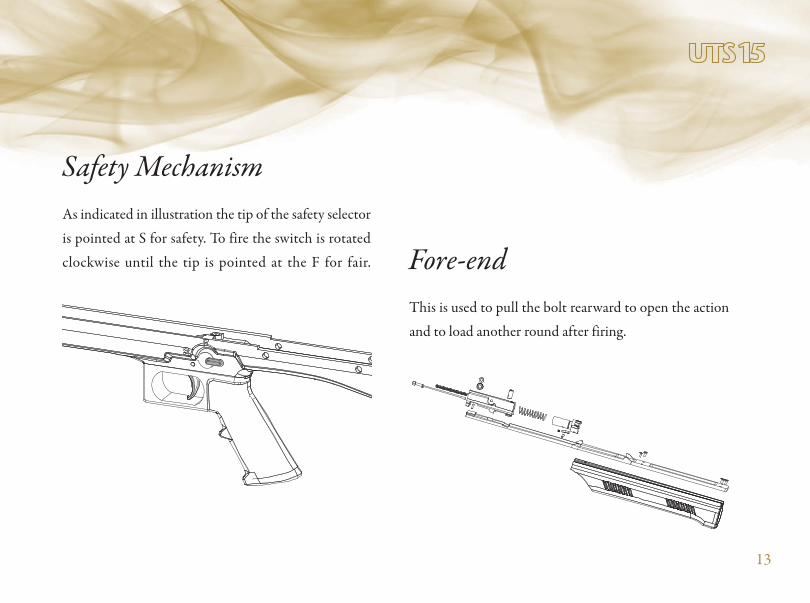
Important Parts & Mechanism 13-15
Loading and Firing 16-23
Unloading 24
Cleaning 25-28
Complete Disassembly 29-51
Exploded View & Part List 52-54
Parts and Service 57


14
(bolt release)

UTS-15 Owners Manual Additions
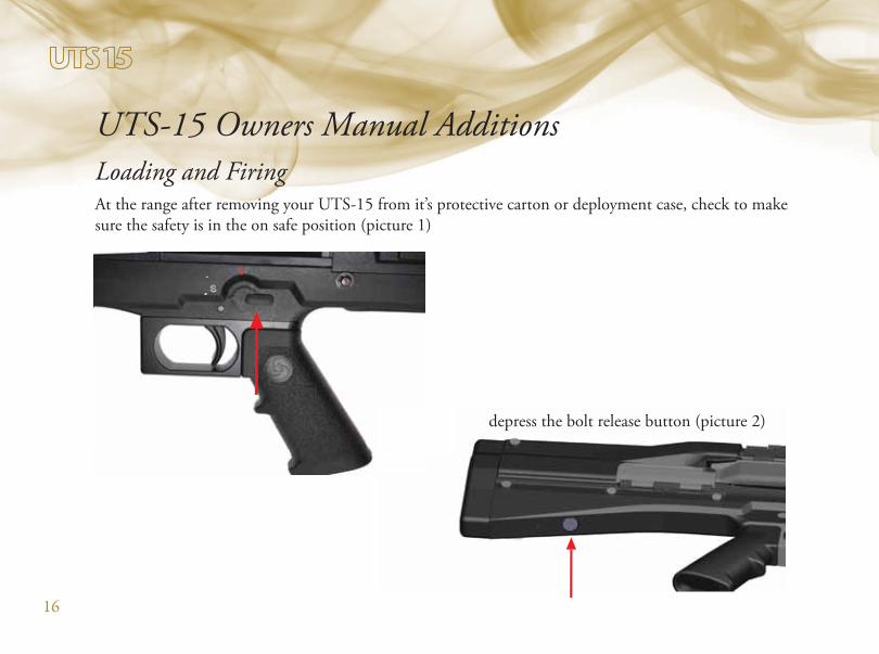
Loading and FiringAt the range after removing your UTS-15 from it’s protective carton or deployment case, check to make
sure the safety is in the on safe position (picture 1)
depress the bolt release button (picture 2)
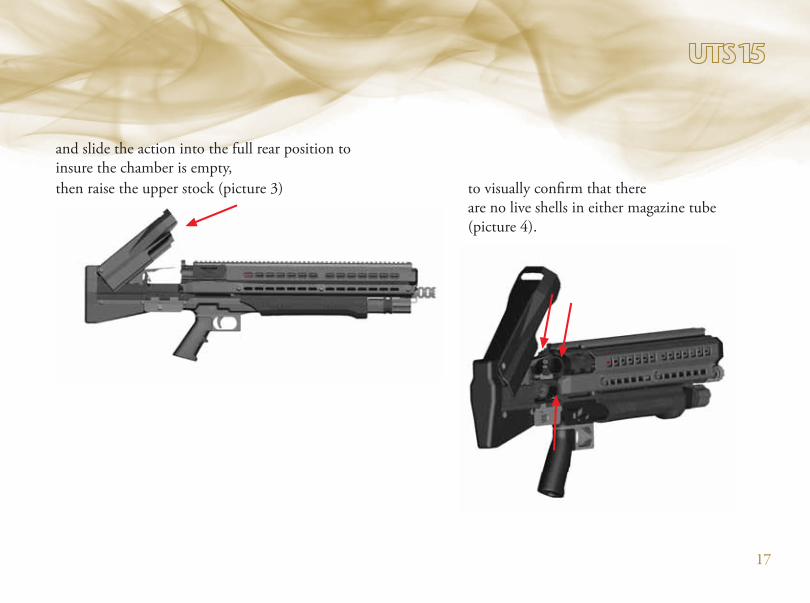
then raise the upper stock (picture 3) to visually confirm that there
are no live shells in either magazine tube
(picture 4).
and slide the action into the full rear position to
insure the chamber is empty,
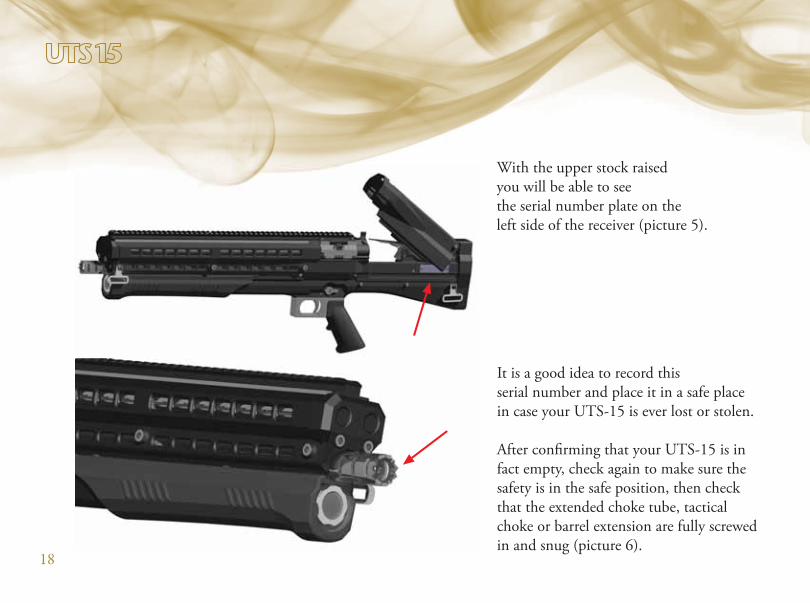
With the upper stock raised
you will be able to see
the serial number plate on the
left side of the receiver (picture 5).
It is a good idea to record this
serial number and place it in a safe place
in case your UTS-15 is ever lost or stolen.
After confirming that your UTS-15 is in
fact empty, check again to make sure the
safety is in the safe position, then check
that the extended choke tube, tactical
choke or barrel extension are fully screwed
in and snug (picture 6).
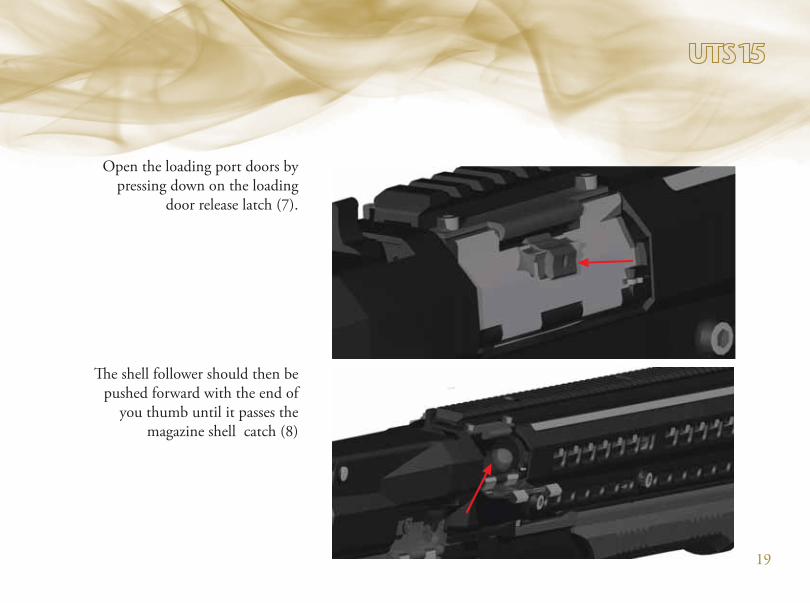
Open the loading port doors by
pressing down on the loading
door release latch (7).
The shell follower should then be
pushed forward with the end of
you thumb until it passes the
magazine shell catch (8)

which will hold the magazine
follower in the magazine tube,
leaving the monobloc port open
to receive shells (9).
When the loading port door is
closed the shells held in the
magazine tube will be released,
charging the full seven 2 ¾” or six
3” shells into the ready to load
position, with an audible sound of
the shells moving rearward to the
rear of the monobloc.
Six 2 ¾” 12 gauge shells or five 3” shells can now be loaded into
each magazine tube; the remaining shell can then be place in the
open monobloc loading port (10).
21
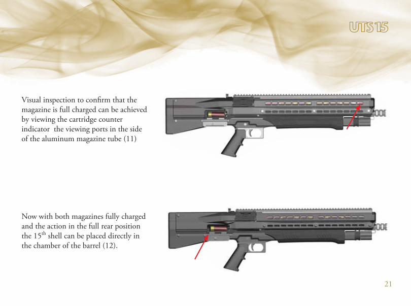
Visual inspection to confirm that the
magazine is full charged can be achieved
by viewing the cartridge counter
indicator the viewing ports in the side
of the aluminum magazine tube (11)
Now with both magazines fully charged
and the action in the full rear position
the 15th shell can be placed directly in
the chamber of the barrel (12).
22
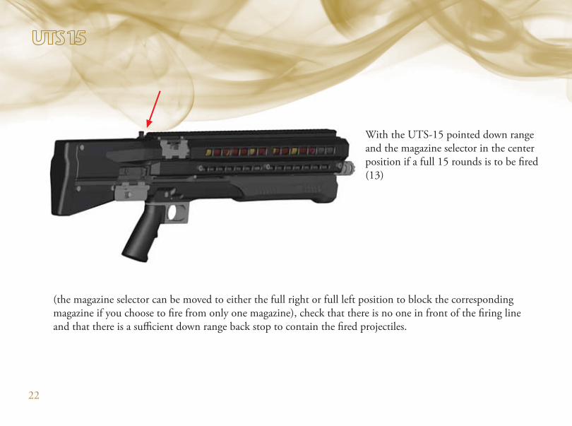
With the UTS-15 pointed down range
and the magazine selector in the center
position if a full 15 rounds is to be fired
(13)
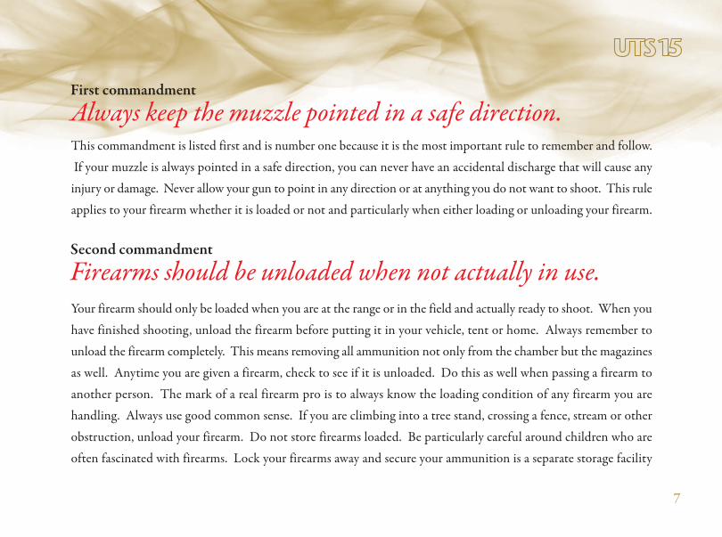
(the magazine selector can be moved to either the full right or full left position to block the corresponding
magazine if you choose to fire from only one magazine), check that there is no one in front of the firing line
and that there is a sufficient down range back stop to contain the fired projectiles.
23
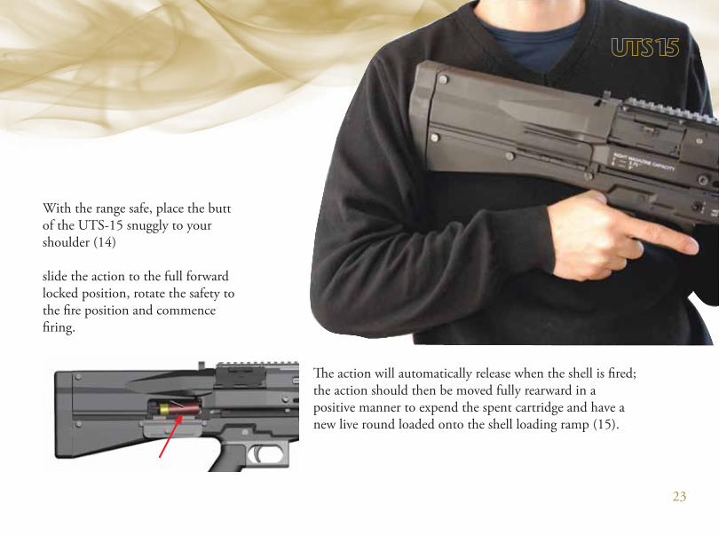
With the range safe, place the butt
of the UTS-15 snuggly to your
shoulder (14)
slide the action to the full forward
locked position, rotate the safety to
the fire position and commence
firing.
The action will automatically release when the shell is fired;
the action should then be moved fully rearward in a
positive manner to expend the spent cartridge and have a
new live round loaded onto the shell loading ramp (15).
24
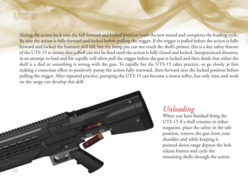
Unloading When you have finished firing the
UTS-15 if a shell remains in either
magazine, place the safety in the safe
position, remove the gun from your
shoulder and while keeping it
pointed down range depress the bolt
release button and cycle the
remaining shells through the action.
Sliding the action back into the full forward and locked position loads the new round and completes the loading cycle.
Be sure the action is fully forward and locked before pulling the trigger. If the trigger is pulled before the action is fully
forward and locked the hammer will fall, but the firing pin can not reach the shell’s primer, this is a key safety feature
of the UTS-15 to insure that a shell can not be fired until the action is fully closed and locked. Inexperienced shooters,
in an attempt to load and fire rapidly will often pull the trigger before the gun is locked and then think that either the
shell is a dud or something is wrong with the gun. To rapidly fire the UTS-15 takes practice, so go slowly at first
making a conscious effort to positively pump the action fully rearward, then forward into the locked position before
pulling the trigger. After repeated practice, pumping the UTS-15 can become a motor reflex, but only time and work
on the range can develop this skill.
24
25
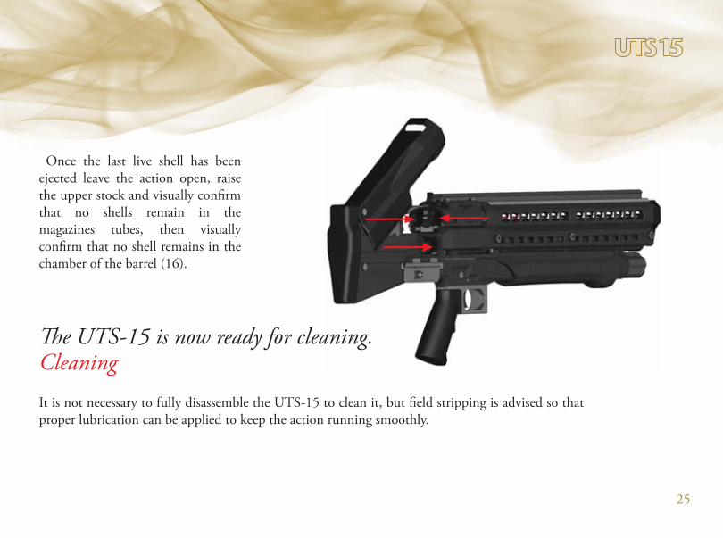
Once the last live shell has been
ejected leave the action open, raise
the upper stock and visually confirm
that no shells remain in the
magazines tubes, then visually
confirm that no shell remains in the
chamber of the barrel (16).
It is not necessary to fully disassemble the UTS-15 to clean it, but field stripping is advised so that
proper lubrication can be applied to keep the action running smoothly.
The UTS-15 is now ready for cleaning. Cleaning

26
To field strip the UTS-15, leave the
upper stock in the raised position,
unscrew and remove the barrel
retaining cap (17).
Then slide the barrel / magazine
assembly forward and lift off (18).
27
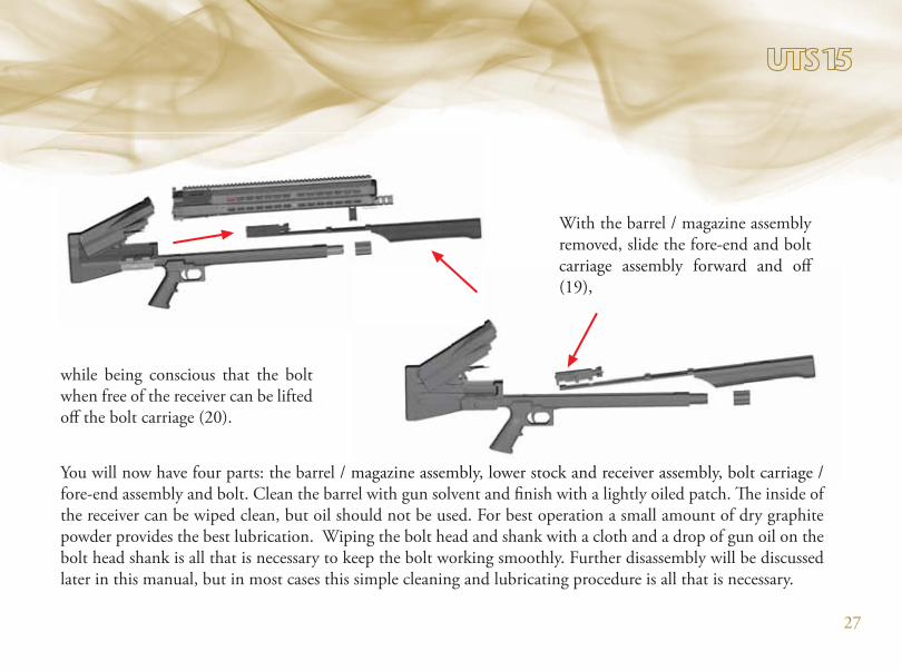
With the barrel / magazine assembly
removed, slide the fore-end and bolt
carriage assembly forward and off
(19),
while being conscious that the bolt
when free of the receiver can be lifted
off the bolt carriage (20).
You will now have four parts: the barrel / magazine assembly, lower stock and receiver assembly, bolt carriage /
fore-end assembly and bolt. Clean the barrel with gun solvent and finish with a lightly oiled patch. The inside of
the receiver can be wiped clean, but oil should not be used. For best operation a small amount of dry graphite
powder provides the best lubrication. Wiping the bolt head and shank with a cloth and a drop of gun oil on the
bolt head shank is all that is necessary to keep the bolt working smoothly. Further disassembly will be discussed
later in this manual, but in most cases this simple cleaning and lubricating procedure is all that is necessary.
carriage assembly forward and off
(19),
magazine assembly, lower stock and receiver assembly, bolt carriage /
l h l d fi h h l h l l d h Th d f

28
Place the bolt on the bolt carriage making sure it is fully down into the
receiving mortises in the bolt carriage. With the upper stock raised, slide the
bolt carriage into the receiver with the bolt release button depressed until the
fore-end is even with the base of the barrel retaining pipe (21).
Now slide the barrel / magazine assembly into the receiver while making sure that the foot of the shell release slide is
between the two bolt carriage extensions (22).
Press down firmly to make
sure the barrel is fully
mounted into the receiver
then replace the barrel
retaining cap making sure it
is screwed down snuggly.
Close the upper stock, slide
the action into the forward
and locked position, then
close the ejection port door.
FURTHER DISSASSEMBLY OF THE UTS-15 BY THE USER IS NOT RECOMMENDED
Field Strip Reassembly

29
Field strip the UTS-15 (see section on field stripping).
Bolt – With a drift punch remove the lateral pin (23) in the
lower rear of the bolt while depressing the firing pin forward
to keep the firing pin spring captured when the lateral pin is
removed.
Remove the firing pin and firing pin spring (24).
Complete disassembly
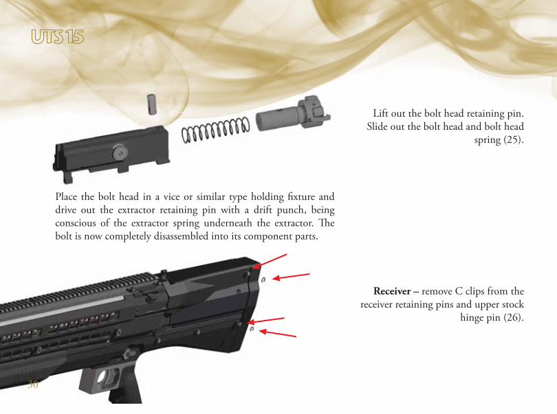
Lift out the bolt head retaining pin.
Slide out the bolt head and bolt head
spring (25).
Receiver – remove C clips from the
receiver retaining pins and upper stock
hinge pin (26).
Place the bolt head in a vice or similar type holding fixture and
drive out the extractor retaining pin with a drift punch, being
conscious of the extractor spring underneath the extractor. The
bolt is now completely disassembled into its component parts.
30
31
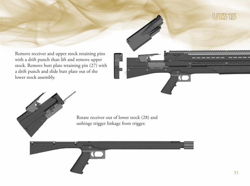
Remove receiver and upper stock retaining pins
with a drift punch than lift and remove upper
stock. Remove butt plate retaining pin (27) with
a drift punch and slide butt plate out of the
lower stock assembly.
Rotate receiver out of lower stock (28) and
unhinge trigger linkage from trigger.
32
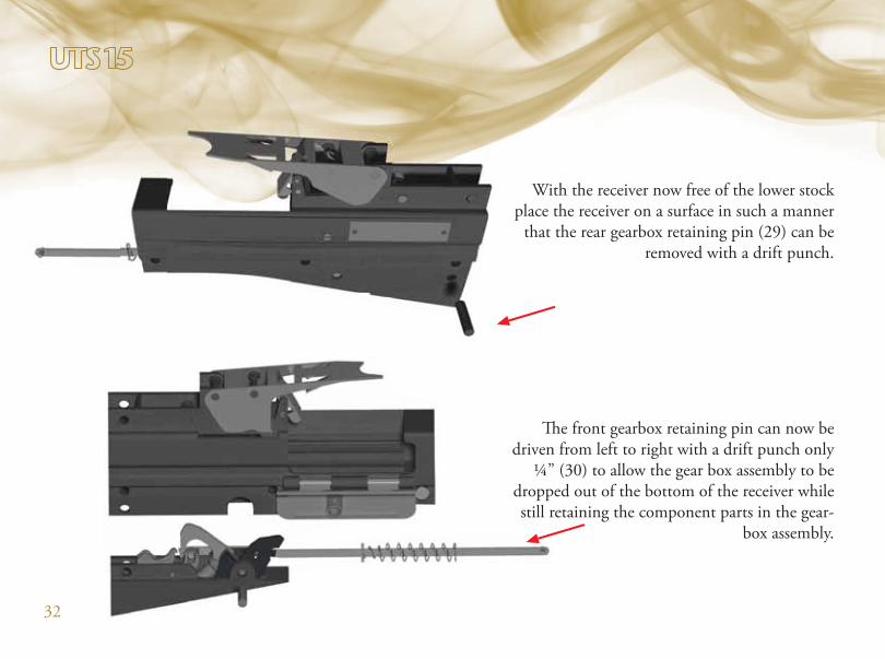
With the receiver now free of the lower stock
place the receiver on a surface in such a manner
that the rear gearbox retaining pin (29) can be
removed with a drift punch.
The front gearbox retaining pin can now be
driven from left to right with a drift punch only
¼” (30) to allow the gear box assembly to be
dropped out of the bottom of the receiver while
still retaining the component parts in the gear-
box assembly.
33
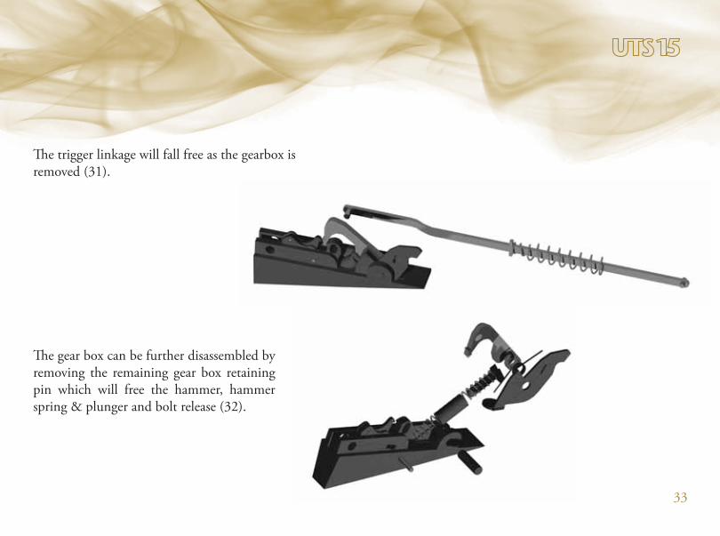
The trigger linkage will fall free as the gearbox is
removed (31).
The gear box can be further disassembled by
removing the remaining gear box retaining
pin which will free the hammer, hammer
spring & plunger and bolt release (32).

34
The sear / secondary sear assembly can be
removed from the gearbox housing by pushing
out the sear pivot pin (33)
with a drift punch. The secondary sear can then
be removed by driving out the secondary sear
pivot pin (34)
while being conscious of the secondary sear
spring retained underneath.

35
The loading mechanism of the receiver can now
be addressed. First remove the C clips from the
mousetrap spring retaining pin (35).
With the receiver held in a vice or similar
holding fixture, hold the mousetrap spring down
by placing a block of wood or similar material
on the spring coils while the mousetrap spring
retaining pin is removed with a drift punch.
Remove the C clips from the mousetrap spoon
pivot and forward pin (36) and remove pins
from assembly.

36
The mousetrap trigger plate and spring is held in
place with a headless screw, with a similar spring
bearing screw directly below (37).
Carefully remove these two screws to complete
the disassembly of the receiver loading mecha-
nisms. Unscrew the ejector spring retaining
screw on the left side of the receiver (38).

37
With the ejector spring retaining screw removed
the ejector spring and pin (39)
may fall free or can be pushed out of
the receiver with a thin screw driver
or wire. Carefully drive the ejection
port door retaining pin (40) out of
the receiver being conscious of the
ejection port door spring; this com-
pletes the disassembly of the receiver.
37

from the stock and drop out the safety spring and plunger (42).
Lower stock – remove the safety spring retaining screw (41)
38

39
Rotate the safety a little over 90°
until the machined clearance flat
on the safety is over the trigger bar
and slide safety out of the
stock(43)
Remove the C clips from the
trigger retaining pin, push
out the pin and lift the
trigger out of the stock (43
A).
39
40
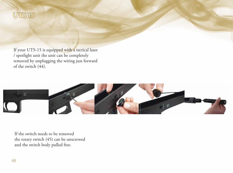
If your UTS-15 is equipped with a tactical laser
/ spotlight unit the unit can be completely
removed by unplugging the wiring just forward
of the switch (44).
If the switch needs to be removed
the rotary switch (45) can be unscrewed
and the switch body pulled free.

41
Barrel / magazine assembly - Remove the
magazine cap (46) by unscrewing the two
forward caps screws

42
being conscious that the magazine cap retains
the magazine springs.
Remove the magazine springs (47)
43
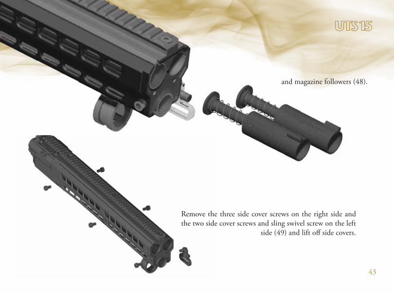
and magazine followers (48).
Remove the three side cover screws on the right side and
the two side cover screws and sling swivel screw on the left
side (49) and lift off side covers.
Remove ttthhh
the twooo sisis d
44
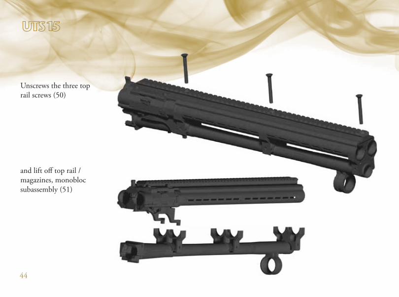
Unscrews the three top
rail screws (50)
and lift off top rail /
magazines, monobloc
subassembly (51)
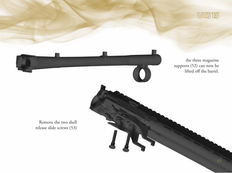
the three magazine
supports (52) can now be
lifted off the barrel.
Remove the two shell
release slide screws (53)
45

46
This will also free the top
rail from the monobloc and
allow the magazine tubes to
be removed from the mono-
bloc as well ( 55 A).
with their washers and
tensions springs and lift
off the shell release slide
(54).

47
Remove the shell stop full right or full left position.
Right behind the shell stop there is a retaining screw
which connects the monoblock to the shell stop.
First unscrew the shell stop retaining screw then
unscrew the shell stop screw. (55 B)
being conscious of the spring and
detent bearing housed in the shell
stop(56).
ull left position.
retaining screw
top.o the shell s
then ning screw t
5 B)op screw. (55
48
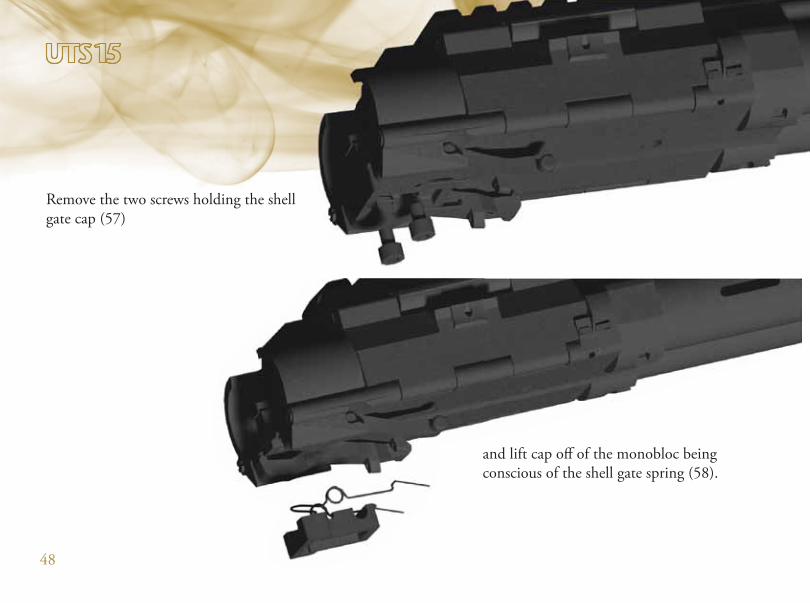
Remove the two screws holding the shell
gate cap (57)
and lift cap off of the monobloc being
conscious of the shell gate spring (58).
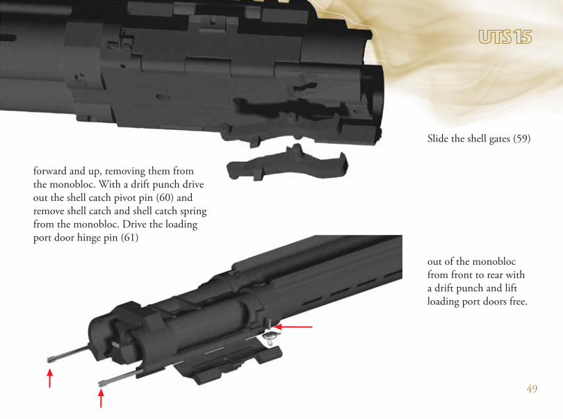
49
Slide the shell gates (59)
out of the monobloc
from front to rear with
a drift punch and lift
loading port doors free.
forward and up, removing them from
the monobloc. With a drift punch drive
out the shell catch pivot pin (60) and
remove shell catch and shell catch spring
from the monobloc. Drive the loading
port door hinge pin (61)
50
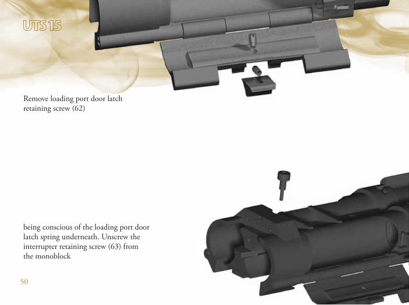
Remove loading port door latch
retaining screw (62)
being conscious of the loading port door
latch spring underneath. Unscrew the
interrupter retaining screw (63) from
the monoblock
51
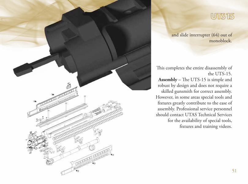
and slide interrupter (64) out of
monoblock.
This completes the entire disassembly of
the UTS-15.
Assembly – The UTS-15 is simple and
robust by design and does not require a
skilled gunsmith for correct assembly.
However, in some areas special tools and
fixtures greatly contribute to the ease of
assembly. Professional service personnel
should contact UTAS Technical Services
for the availability of special tools,
fixtures and training videos.

52

53
1 FRONT MAGAZINE CAP 12 FRONT MAGAZINE CAP SCREWS 23 MAGAZINE FOLLOWER BODY LEFT & RIGHT 24 MAGAZINE FOLLOWER PLUNGER 25 MAGAZINE FOLLOWER SPRING 26 RIGHT MAGAZINE TUBE 17 LEFT MAGAZINE TUBE 18 MAGAZINE TUBE SPRING 29 MONOBLOCK BODY 110 SHELL RELEASE PLATE 111 SHELL RELEASE PLATE SCREW 212 RIGHT SHELL RELEASE GATE 113 LEFT SHELL RELEASE GATE 114 SHELL RELEASE GATE SPRING 115 SHELL FEED GATE CAP 116 SHELL FEED GATE SCREW 217 INTERRUPTER 118 INTERRUPTER SCREW 119 SHELL STOP 120 SHELL STOP SCREW 121 SHELL STOP SPRING 122 SHELL STOP BALL 4 MM 123 RIGHT LOADING PORT DOOR 124 LEFT LOADING PORT DOOR 125 LOADING PORT HINGE PIN 226 TOP RAIL 127 LOADING PORT DOOR SCREW 428 TOP RAIL SCREW 329 FRONT MAGAZINE SUPPORT 130 MIDDLE & REAR MAGAZINE SUPPORT 231 RIGHT SIDE COVER 132 LEFT SIDE COVER 133 SIDE COVER SCREW 534 SIDE COVER SCREW WITH HOLE 135 BARREL 136 BARREL EXTENSION 137 EXTENDED CHOKE TUBE 138 BARREL HANGER 139 BARREL STUDS 340 FORE-END 141 FORE-END SCREW 442 BOLT CARRIAGE 143 BOLT BODY 144 BOLT HEAD 145 FIRING PIN 146 FIRING PIN SPRING 147 BOLT HEAD SPRING 148 BOLT HEAD PIN 149 FIRING PIN RETAINING PIN 150 BOLT WHEEL 151 BOLT WHEEL SCREW 152 EXTRACTOR 1
WİEW DESCRIPTION QTY53 EXTRACTOR PIN 154 EXTRACTOR SPRING 155 MAGAZINE CAP 156 MAGAZINE CAP SPRING 157 LOWER STOCK 158 TRIGGER GUARD 159 LOWER STOCK MAGAZINE TUBE 160 TRIGGER 161 TRIGGER PIN 162 SAFETY 163 SAFETY BALL 3 MM 164 SAFETY SPRING 165 PISTOL GRIP 166 PISTOL GRIP SCREW 167 TRIGGER GUARD SCREW 268 GEAR BOX BODY 169 HAMMER 170 BOLT RELEASE 171 HAMMER/BOLT RELEASE PIN 172 BOLT RELEASE SPRING 173 HAMMER SPRING 174 HAMMER SPRING PLUNGER 175 SEAR 176 SECONDARY SEAR 177 SEAR PIN 178 SECONDARY SEAR PIN 179 SECONDARY SEAR RETAINING PIN 180 SECONDARY SEAR SPRING 181 TRIGGER LINKAGE 182 HAMMER SPRING HOUSING 183 TRIGGER LINKAGE SPRING 184 RECEIVER 185 RECEIVER PLATE 186 EJECTION PORT DOOR 187 EJECTION PORT DOOR MAGNET 188 EJECTION PORT DOOR SPRING 189 EJECTION PORT HINGE PIN 190 MOUSE TRAP PIN 191 MOUSE TRAP SPOON 192 MOUSE TRAP FORWARD PIN 193 MOUSE TRAP SPRING 194 MOUSE TRAP SPRING RETAINING PIN 195 MOUSE TRAP TRIGGER PLATE 196 MOUSE TRAP TRIGGER PLATE PIN 197 MOUSE TRAP TRIGGER PLATE LOWER PIN 198 MOUSE TRAP TRIGGER PLATE SPRING 199 EJECTOR PIN 1100 EJECTION PORT MAGNET HOUSING 1101 EJECTOR SPRING RETAINING SCREW 1102 EJECTOR SPRING 1103 RECEIVER RETAINING PINS 1104 MIDDLE RECEIVER RETAINING PIN 2
WİEW DESCRIPTION QTY105 REAR GEAR BOX PIN 1106 BUTT PLATE 1107 RECOIL PAD 1108 UPPER RETAINING PIN 1109 UPPER STOCK 1110 UPPER STOCK RETAINING PIN 1111 SLING SWIVELS 2112 FRONT SIGHT 1113 SIGHT PIN 1114 FRONT SIGHT CLAMP 1115 FRONT SIGHT CLAMP SCREW 2116 SET SCREW 1117 REAR SIGHT 1118 REAR SIGHT SPRING 1119 REAR SIGHT APERTURE 1120 WINDAGE SCREW 1121 WINDAGE ADJUSTMENT KNOB 1122 WINDAGE KNOB PIN 1123 REAR SIGHT CLAMP SCREW 2124 REAR SIGHT CLAMP 1125 7,5'' BARREL EXTENSION 1126 TAKE DOWN TOOL 1127 WINDAGE ADJUSTMENT KNOP SPRING 1128 WINDAGE ADJUSTMENT KNOP BALL 3MM 1129 LASER / FLASHLIGHT UNIT 1130 FLASHLIGHT LENS 1131 C CLIPS (3 MM) 2132 C CLIPS (4 MM) 6133 C CLIPS (5 MM) 4134 O-RING 1135 SAFETY SCREW 1136 LEFT &RIGHT MAGAZINE TUBE RIVETS 4137 SHELL RELEASE PLATE SPRING 2138 SHELL RELEASE PLATE SCREW FLAT WASHER 2139 PISTOL GRIP SCREW SERRATED WASHER 1140 TRIGGER GUARD SCREW SERRATED WASHER 2141 MONOBLOCK BODY EXTRACTOR 2142 MONOBLOCK BODY EXTRACTOR SPRING 2143 MONOBLOCK BODY EXRACTOR PIN 2144 LOADING PORT DOOR LOCK SLİDE 2145 LOADING PORT DOOR LOCK SLİDE SPRING 2146 LOADING PORT DOOR LOCK SLİDE SCREW 2148 EXTENDED CHOKE TUBE CYLINDER SHORT 1149 LASER / FLASHLIGHT SWITCH COVER 1150 LOWER RECEIVER MAGAZINE TUBE LASER CAP 1151 MAGAZINE CAP PIN 1154 RED FLASHLIGHT UNIT 1155 GREEN FLASHLIGHT UNIT 1163 SHELL STOP RETAINING SCREW 1164 LASER / FLASHLIGHT SWITCH HOLE PLUG 2165 LASER / FLASHLIGHT TRIPLE SWITCH COVER 1
WİEW DESCRIPTION QTY

54

55
56