UTP 4x2x24 AWG Cat 5e - Amazon Simple Storage Service · PDF file · 2013-07-30UTP...
36
Transcript of UTP 4x2x24 AWG Cat 5e - Amazon Simple Storage Service · PDF file · 2013-07-30UTP...


1
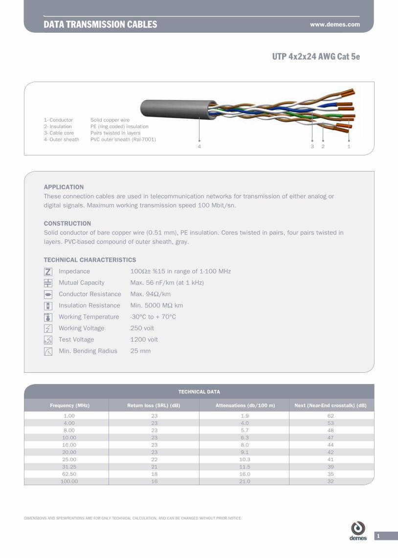
UTP 4x2x24 AWG Cat 5e
DATA TRANSMISSION CABLES www.demes.com
DIMENSIONS AND SPESIFICATIONS ARE FOR ONLY TECHNICAL CALCULATION, AND CAN BE CHANGED WITHOUT PRIOR NOTICE.
1- Conductor Solid copper wire2- Insulation PE (ring coded) insulation3- Cable core Pairs twisted in layers 4- Outer sheath PVC outer sheath (Ral-7001)
APPLICATIONThese connection cables are used in telecommunication networks for transmission of either analog or
digital signals. Maximum working transmission speed 100 Mbit/sn.
CONSTRUCTION
Solid conductor of bare copper wire (0.51 mm), PE insulation. Cores twisted in pairs, four pairs twisted in
layers. PVC-based compound of outer sheath, gray.
TECHNICAL CHARACTERISTICS
Impedance 100Ω±%15inrangeof1-100MHz
MutualCapacity Max.56nF/km(at1kHz)
ConductorResistance Max.94Ω/km
InsulationResistance Min.5000MΩkm
Working Temperature -30°C to + 70°C
Working Voltage 250 volt
Test Voltage 1200 volt
Min. Bending Radius 25 mm
1.00 23 1.9 62
4.00 23 4.0 53
8.00 23 5.7 48
10.00 23 6.3 47
16.00 23 8.0 44
20.00 23 9.1 42
25.00 22 10.3 41
31.25 21 11.5 39
62.50 18 16.0 35
100.00 16 21.0 32
TECHNICAL DATA
Frequency (MHz) Return loss (SRL) (dB) Attenuations (db/100 m) Next (Near-End crosstalk) (dB)
1234

2
DATA TRANSMISSION CABLES
DIMENSIONS AND SPESIFICATIONS ARE FOR ONLY TECHNICAL CALCULATION, AND CAN BE CHANGED WITHOUT PRIOR NOTICE.
TECHNICAL DATA
Frequency (MHz) Return loss (SRL) (dB) Attenuations (db/100 m) Next (Near-End crosstalk) (dB)
S/UTP 4x2x24 AWG Cat 5eF/UTP 4x2x24 AWG Cat 5e
1- Conductor Solid copper wire2- Insulation PE (ring coded) insulation3- Cable Base Pairs twisted in layers4- Wrapping Tape PES tape 5- Drain wire Tinned copper wire 6- Screen ALPES tape7- Outer Sheath PVC outer sheath, gray (Ral-7001)
APPLICATIONThese connection cables are used in telecommunication networks for transmission of either analog or digital
signals. Maximum working transmission speed 100 Mbit/sn.
CONSTRUCTION
Solid conductor of bare copper wire (0.51 mm), PE insulation. Cores twisted in pairs, four pairs twisted in
layers, over the base polyster foil wrapping tape, tinned copper drain wire, over the cable static screen of plas-
tic coated aluminum foil (AL-PES). PVC-based compound of outer sheath, gray.
TECHNICAL CHARACTERISTICS
Impedance 100Ω±%15inrangeof1-100MHz
MutualCapacity Max.56nF/km(at1kHz)
ConductorResistance Max.94Ω/km
InsulationResistance Min.5000MΩkm
Working Temperature -30°C to + 70°C
Working Voltage 250 volt
Test Voltage 1200 volt
Min. Bending Radius 25 mm
1.00 23 1.9 62
4.00 23 4.0 53
8.00 23 5.7 48
10.00 23 6.3 47
16.00 23 8.0 44
20.00 23 9.1 42
25.00 22 10.3 41
31.25 21 11.5 39
62.50 18 16.0 35
100.00 16 21.0 32
1234 567

3
www.demes.com
DIMENSIONS AND SPESIFICATIONS ARE FOR ONLY TECHNICAL CALCULATION, AND CAN BE CHANGED WITHOUT PRIOR NOTICE.
STP 4x2x24 AWG Cat 5eF/FTP 4x2x24 AWG Cat 5e
TECHNICAL DATA
Frequency (MHz) Return loss (SRL) (dB) Attenuations (db/100 m) Next (Near-End crosstalk) (dB)
1.00 23 1.9 62
4.00 23 4.0 53
8.00 23 5.7 48
10.00 23 6.3 47
16.00 23 8.0 44
20.00 23 9.1 42
25.00 22 10.3 41
31.25 21 11.5 39
62.50 18 16.0 35
100.00 16 21.0 32
1- Conductor Solid copper wire2- Insulation PE (ring coded) insulation3- Pairs Screened twisted pairs4- Cable Base Pairs twisted in layers5- Wrapping Tape PES tape6- Drain Tinned copper wire7- Screen AL-PES-AL tape8- Outer Sheath PVC outer sheath, gray (RAL-7001)
APPLICATIONThese connection cable are used in telecommunication networks for transmission of either analog or digital
signals. Maximum working transmission speed 100 Mbit/sn.
CONSTRUCTION
Solid conductor of bare copper wire (0.51 mm), PE insulation. Cores twisted in pairs, four individual screened
pairs twisted in layers. Over the screened pairs twisted in layers; polyester tape, tinned copper wire and
ALPESAL tape applied. PVC-based compound of outer sheath, gray.
TECHNICAL CHARACTERISTICS
Impedance 100Ω±%15inrangeof1-100MHz
MutualCapacity Max.56nF/km(at1kHz)
ConductorResistance Max.94Ω/km
InsulationResistance Min.5000MΩkm
Working Temperature -30°C to + 70°C
Working Voltage 250 volt
Test Voltage 1200 volt
Min. Bending Radius 25 mm
1236 4578
4
DATA TRANSMISSION CABLES
DIMENSIONS AND SPESIFICATIONS ARE FOR ONLY TECHNICAL CALCULATION, AND CAN BE CHANGED WITHOUT PRIOR NOTICE.
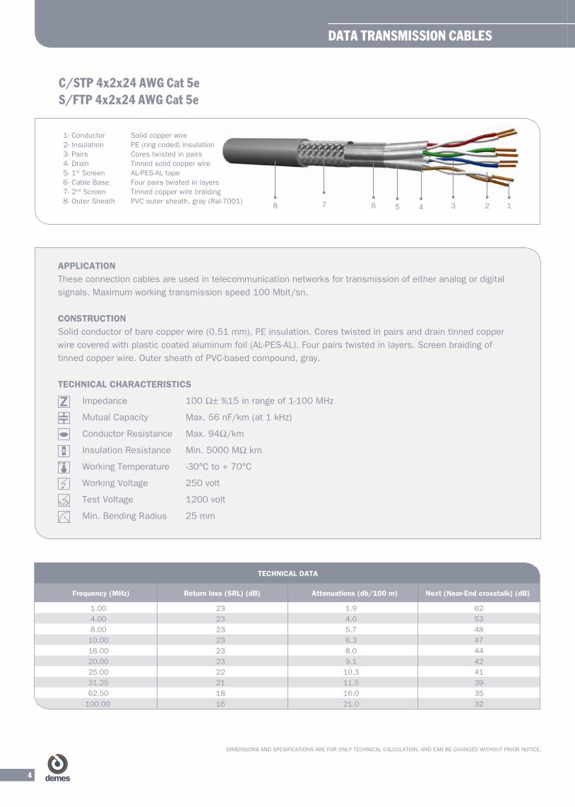
C/STP 4x2x24 AWG Cat 5eS/FTP 4x2x24 AWG Cat 5e
TECHNICAL DATA
Frequency (MHz) Return loss (SRL) (dB) Attenuations (db/100 m) Next (Near-End crosstalk) (dB)
1.00 23 1.9 62
4.00 23 4.0 53
8.00 23 5.7 48
10.00 23 6.3 47
16.00 23 8.0 44
20.00 23 9.1 42
25.00 22 10.3 41
31.25 21 11.5 39
62.50 18 16.0 35
100.00 16 21.0 32
APPLICATIONThese connection cables are used in telecommunication networks for transmission of either analog or digital
signals. Maximum working transmission speed 100 Mbit/sn.
CONSTRUCTION
Solid conductor of bare copper wire (0.51 mm), PE insulation. Cores twisted in pairs and drain tinned copper
wire covered with plastic coated aluminum foil (AL-PES-AL). Four pairs twisted in layers. Screen braiding of
tinned copper wire. Outer sheath of PVC-based compound, gray.
TECHNICAL CHARACTERISTICS
Impedance 100Ω±%15inrangeof1-100MHz
MutualCapacity Max.56nF/km(at1kHz)
ConductorResistance Max.94Ω/km
InsulationResistance Min.5000MΩkm
Working Temperature -30°C to + 70°C
Working Voltage 250 volt
Test Voltage 1200 volt
Min. Bending Radius 25 mm
8 6 457 3 2 1
1- Conductor Solid copper wire2- Insulation PE (ring coded) insulation3- Pairs Cores twisted in pairs4- Drain Tinned solid copper wire5- 1st Screen AL-PES-AL tape6- Cable Base Four pairs twisted in layers 7- 2nd Screen Tinned copper wire braiding 8- Outer Sheath PVC outer sheath, gray (Ral-7001)

5
www.demes.com
DIMENSIONS AND SPESIFICATIONS ARE FOR ONLY TECHNICAL CALCULATION, AND CAN BE CHANGED WITHOUT PRIOR NOTICE.
U/UTP 4x2x26 AWG Cat 5eF/UTP 4x2x26 AWG Cat 5e
APPLICATIONThese connection cables are used in telecommunication networks for transmission of either analog or digital
signals. Maximum working transmission speed 100 Mbit/sn.
CONSTRUCTION Fine stranded copper wire (7x0.16 mm), PE insulation. Cores twisted in pairs, four pairs twisted in layers. PVC-
based compound of outer sheath, gray.
TECHNICAL CHARACTERISTICS
Impedance 100Ω±%15inrangeof1-100MHz
MutualCapacity Max.56nF/km(at1kHz)
ConductorResistance Max.138.Ω/km
InsulationResistance Min.5000MΩkm
Working Temperature -30°C to + 70°C
Working Voltage 250 volt
Test Voltage 500 volt
Min. Bending Radius 25 mm
1- Conductor Stranded copper wire (7x0.16 mm)2- Insulation PE (ring coded) insulation3- Cable Core Pairs twisted in layers4- Outer Sheath PVC outer sheath, gray (Ral-7001)
TECHNICAL DATA
Frequency (MHz) Return loss (SRL) (dB) Attenuations (db/100 m) Next (Near-End crosstalk) (dB)
1.0 23 3.2 62
4.0 23 6.5 53
8.0 23 8.0 48
10.0 23 9.9 47
16.0 23 12.3 44
20.0 23 13.8 42
25.0 22 15.9 41
31.25 21 17.9 39
62.50 18 25.7 35
100.0 16 33.0 32
1234

6
DATA TRANSMISSION CABLES
DIMENSIONS AND SPESIFICATIONS ARE FOR ONLY TECHNICAL CALCULATION, AND CAN BE CHANGED WITHOUT PRIOR NOTICE.
FS/UTP 4x2x24 AWG Cat 5e F/UTP 4x2x24 AWG Cat 5e
APPLICATIONThese connection cable are used in telecommunication networks for transmission of either analog or digital
signals. Special flexible design for patch panels. Maximum working transmission speed 100 Mbit.
CONSTRUCTION Fine stranded cooper wire (7x0.20mm) conductor, solid PE insulation. Cores twisted in pairs, four pairs twisted
in layers. Polyster wrapping tape. Multi stranded tinned copper wire drain wire. Screen of plastic coated
aluminum foil. PVC-based compound of outer sheath, gray. (RAL 7001)
TECHNICAL CHARACTERISTICS
Impedance 100Ω±%15inrangeof1-100MHz
MutualCapacity Max.56nF/km(at1kHz)
ConductorResistance Max.88.Ω/km
InsulationResistance Min.5000MΩkm
Working Temperature -30°C to + 70°C
Working Voltage 250 volt
Test Voltage 1200 volt
Min. Bending Radius 25 mm
1- Conductor Stranded copper wire (7x0.20 mm)2- Insulation PE (ring coded) insulation3- Cable Core Pairs twisted in layers4- Wrapping Tape Polyster tape5- Drain Multi stranded tinned copper wire6- Screen AL-PES tape7- Outer Sheath PVC outer sheath, gray (Ral-7001)
TECHNICAL DATA
Frequency (MHz) Return loss (SRL) (dB) Attenuations (db/100 m) Next (Near-End crosstalk) (dB)
1.0 23.0 2.2 62
4.0 23.0 4.8 53
8.0 23.0 6.4 48
10.0 23.0 7.5 47
16.0 23.0 8.7 44
20.0 23.0 10.2 42
25.0 22.0 12.0 41
31.25 21.0 13.9 39
62.50 18.0 19.7 35
100.0 16.0 24.0 32
6 547
3 2 1

7
www.demes.com
DIMENSIONS AND SPESIFICATIONS ARE FOR ONLY TECHNICAL CALCULATION, AND CAN BE CHANGED WITHOUT PRIOR NOTICE.
FC/UTP 4x2x26 AWG Cat 5eS/UTP 4x2x26 AWG Cat 5e
TECHNICAL DATA
Frequency (MHz) Return loss (SRL) (dB) Attenuations (db/100 m) Next (Near-End c rosstalk) (dB)
APPLICATIONThese connection cables are used in telecommunication networks for transmission of either analog or digital
signals. Special flexible design for patch panels. Maximum working transmission speed 100 Mbit.
CONSTRUCTION
Fine stranded copper wire (7x0.20 mm) conductor, solid PE insulation. Cores twisted in pairs, four pairs
twisted in layers. Polyster wrapping tape. Screen braiding of tinned copper wire. Outer sheath of PVC-based
compound, gray (RAL 7001).
TECHNICAL CHARACTERISTICS
Impedance 100Ω±%15inrangeof1-100MHz
MutualCapacity Max.56nF/km(at1kHz)
ConductorResistance Max.138.Ω/km
InsulationResistance Min.5000MΩkm
Working Temperature -30°C to + 70°C
Working Voltage 250 volt
Test Voltage 1200 volt
Min. Bending Radius 26 mm
1.0 23.0 3.2 62
4.0 23.0 6.5 53
8.0 23.0 8.0 48
10.0 23.0 9.9 47
16.0 23.0 12.3 44
20.0 23.0 13.8 42
25.0 22.0 15.9 41
31.25 21.0 17.9 39
62.50 18.0 25.7 35
100.0 16.0 33.0 32
1- Conductor Stranded copper wire (7x0.16 mm)2- Insulation PE (ring coded) insulation3- Cable Core Pairs twisted in layers4- Wrapping Tape Polyster tape5- Screen Tinned copper wire braiding6- Outer Sheath PVC outer sheath, gray (Ral-7001)
6 5 4 3 2 1

8
DATA TRANSMISSION CABLES
1- Conductor Solid copper wire (0.51 mm)2- Insulation Polyolefin (ring coded)3- Cable Core Pairs twisted in layers4- Outer Sheath PVC-based, gray (Ral-7001, Ral-7032)
APPLICATIONThese connection cables are used in telecommunication networks for transmission of either analog or digital
signals. Maximum working transmission speed 125 Mbit/sn.
CONSTRUCTION Solid conductor of bare copper wire (0.51 mm), Polyelefin insulation. Cores twisted in pairs, four screened
pairs twisted in layers. PVC-based compound of outer sheath, gray.
TECHNICAL CHARACTERISTICS
Impedance 100Ω±%15inrangeof1-100MHz
100Ω±%22inrangeof125MHz
EfectiveCapacity Max.56nF/km(at1kHz)
ConductorResistance Max.94.Ω/km
Insulation Resistance Min. 5000 MW.km
Temperature Range -30°C to + 70°C
Working Voltage 250 volt
Test Voltage 1200 volt
Min. Bending Radius 25 mm
TECHNICAL DATA
Frequency (MHz) Return loss (SRL) (dB) Attenuations (db/100 m) Next (Near-End crosstalk) (dB)
1.0 23 2.1 72
4.0 23 3.8 63
8.0 24.5 5.8 58
10.0 25 6.0 57
16.0 25 7.6 54
20.0 25 8.5 53
25.0 24.3 10.3 51
31.25 23.6 10.8 50
62.5 21.5 15.5 45
100.0 20.1 19.9 42
125 19.4 22.5 41
200 18 29.2 38
250 17.3 33.0 36
UTP 4x2x24 AWG Cat 6
1234

9
www.demes.com
DIMENSIONS AND SPESIFICATIONS ARE FOR ONLY TECHNICAL CALCULATION, AND CAN BE CHANGED WITHOUT PRIOR NOTICE.
RS 232/00
APPLICATIONThese connection cables are used in telecommunication networks and electronic control systems for signal
transmission.
CONSTRUCTION Fine stranded tinned annealed copper wire, semi rigid PVC-based insulation. Cores twisted in pairs, pairs
twisted in layers, polyster wrapping tape with drain stranded annealed tinned copper wire. Screen braiding of
tinned copper wire. Outer sheath of PVC- based compound, gray (RAL-7032).
TECHNICAL CHARACTERISTICS
Mutual Capacity AWG 22.24 : max. 100 nF/km
AWG 20 : max. 120 nF/km
Working Temperature -30°C to + 70°C
InsulationResistance ≥50MΩ
Working Voltage 250 volt
Test Voltage 1200 volt
Min. Bending Radius 15xCable diameter
1- Conductor Fine stranded tinned annealed copper wire2- Insulation PVC insulation3- Wrapping Tape PES tape4- Drain Stranded tinned copper wire5- Screen Tinned copper wire braiding6- Outer Sheath PVC outer sheath, gray (Ral-7032)
TECHNICAL DATA
Number of cores and Approx. outside diameter (mm) Copper factorial (per km) Approx. weigth (kg/km) cross-section (mm2)
DAT-232/00 AWG 24
2x2x0.22 6.4 29.1 67.4
3x2x0.22 6.7 34.2 76.5
4x2x0.22 7.2 42.6 89.9
5x2x0.22 8.2 47.2 109.5
6x2x0.22 8.8 55.2 123.4
7x2x0.22 8.8 59.4 130.4
8x2x0.22 9.3 64.2 140.5
9x2x0.22 10.3 72.4 156.4
10x2x0.22 10.4 77.5 165.0
12x2x0.22 10.8 87.8 183.0
14x2x0.22 11.5 98.9 203.0
16x2x0.22 12.1 109.9 222.7
4
356
21

10
DIMENSIONS AND SPESIFICATIONS ARE FOR ONLY TECHNICAL CALCULATION, AND CAN BE CHANGED WITHOUT PRIOR NOTICE.
RS 232/00
TECHNICAL DATA
Number of cores and Approx. outside diameter (mm) Copper factorial (per km) Approx. weigth (kg/km) cross-section (mm2)
DAT-232/00 AWG 24
18x2x0.22 12.6 122.8 244.2
20x2x0.22 13.2 133.6 263.3
25x2x0.22 14.6 178.1 329.2
DAT-232/00 AWG 22 2x2x0.34 7.5 39.2 77.1
3x2x0.34 7.8 47.7 91.3
4x2x0.34 8.5 57.1 107.7
5x2x0.34 9.2 67.0 125.1
6x2x0.34 10.1 76.1 146.5
7x2x0.34 10.1 83.7 158.1
8x2x0.34 10.7 92.8 174.3
9x2x0.34 12.3 104.3 207.3
10x2x0.34 12.4 111.8 219.7
12x2x0.34 13.0 127.3 246.5
14x2x0.34 14.0 159.5 292.7
16x2x0.34 14.7 177.1 322.9
18x2x0.34 15.4 194.8 352.9
20x2x0.34 16.0 211.5 381.6
25x2x0.34 17.5 253.9 453.4
DAT-232/00 AWG 20 2x2x0.5 8.8 52.7 102.0
3x2x0.5 9.3 64.6 122.8
4x2x0.5 10.1 78.4 147.2
5x2x0.5 11.0 92.2 172.1
6x2x0.5 12.1 106.2 202.9
7x2x0.5 12.1 116.4 219.8
8x2x0.5 13.1 144.6 259.6
9x2x0.5 15.0 162.9 306.3
10x2x0.5 15.1 174.0 325.3
12x2x0.5 15.8 198.5 367.3
14x2x0.5 16.8 224.4 412.8
16x2x0.5 17.7 249.7 457.2
18x2x0.5 18.6 274.7 501.1
20x2x0.5 19.4 299.7 544.6
25x2x0.5 21.3 361.9 652.2
DATA TRANSMISSION CABLES

11
DIMENSIONS AND SPESIFICATIONS ARE FOR ONLY TECHNICAL CALCULATION, AND CAN BE CHANGED WITHOUT PRIOR NOTICE.
RS 422/00
APPLICATIONThese connection cables are used in telecommunication networks and electronic control systems for signal
transmission.
CONSTRUCTION Fine stranded tinned annealed copper wire, PE core insulation. Cores twisted in pairs, pairs twisted in layers,
polyster wrapping tape. Screen of aluminum coated polyester foil. Screen braiding of tinned copper wire with
tinned copper wire drain. Outer sheath of PVC- based compound, gray. (RAL-7032)
TECHNICAL CHARACTERISTICS
Mutual Capacity max. 50 nF/km
Working Temperature -30°C to + 80°C
InsulationResistance ≥5GΩkm
Working Voltage 250 volt
Test Voltage 1200 volt
Min. Bending Radius 15xCable diameter
2x2x0.22 7.0 30 72
3x2x0.22 7.4 35 81
4x2x0.22 7.9 44 94
5x2x0.22 8.6 51 107
6x2x0.22 9.5 57 124
7x2x0.22 9.5 62 130
8x2x0.22 10.0 70 143
10x2x0.22 11.2 81 164
15x2x0.22 12.9 121 222
20x2x0.22 14.4 146 266
1- Conductor Stranded tinned copper wire 2- Insulation PE insulation3- Wrapping Tape Polyster tape4- Screen AL-PES tape5- Drain Stranded tinned copper wire6- Screen Tinned copper wire braiding7- Outer Sheath PVC outer sheath, gray (Ral-7032) 67 4 3 5 2 1
www.demes.com
TECHNICAL DATA
Number of cores and Approx. outside diameter (mm) Copper factorial (per km) Approx. weigth (kg/km) cross-section (mm2)
DAT-422/00 AWG 24

12
DIMENSIONS AND SPESIFICATIONS ARE FOR ONLY TECHNICAL CALCULATION, AND CAN BE CHANGED WITHOUT PRIOR NOTICE.
RS 422/00
TECHNICAL DATA
Number of cores and Approx. outside diameter (mm) Copper factorial (per km) Approx. weigth (kg/km) cross-section (mm2)
DAT-422/00 AWG 22
2x2x0.34 8.2 44 85
3x2x0.34 8.6 51 98
4x2x0.34 9.4 59 113
5x2x0.34 10.2 72 133
6x2x0.34 11.2 79 154
7x2x0.34 11.2 86 163
8x2x0.34 11.9 99 183
10x2x0.34 13.9 130 243
15x2x0.34 16.1 191 334
20x2x0.34 18.0 235 407
DAT-422/00 AWG 20
2x2x0.5 8.6 53.4 99
3x2x0.5 9.1 63.9 116
4x2x0.5 9.9 77.6 138
5x2x0.5 10.8 91.7 161
6x2x0.5 12.1 120.1 205
7x2x0.5 12.1 130.7 220
8x2x0.5 12.8 143.0 241
10x2x0.5 14.8 173.8 304
DATA TRANSMISSION CABLES

13
DIMENSIONS AND SPESIFICATIONS ARE FOR ONLY TECHNICAL CALCULATION, AND CAN BE CHANGED WITHOUT PRIOR NOTICE.
TWINAXIAL105Ω
APPLICATIONThese LAN data transmission cables are used for ethernet networks. Can be used to link main units, Data
transmission speed is 10 mbit/s.
CONSTRUCTIONSolid electrolitic copper wire, Foam PE insulation. Screen of aluminum coated polyester foil (AL-PES). Screen
braiding of tinned copper wire. Screen of aluminum coated polyester foil; two sided (AL-PES-AL). Screen
braiding of tinned copper wire. Outer sheath of PVC compound, yellow.
TECHNICAL CHARACTERISTICS
Impedance 50±2Ω
Efective capacity max. 85 nF/m
Conductorresistance max.4.7Ω/km
Insulationresistance min.5.000MΩkm
Temperature range -30°C to +70°C
Working voltage max. 2.5 V
Test voltage max. 5.0 V
Min. bending radius 200 mm
TECHNICAL DATA
Frequency (MHz) 100 200 400 600 800
Attenuation (db/100 m) 5.5 7.7 11 14.4 16.8
1- Conductor Solid electrolitic copper wire2- Insulation Foam PE3- Paired cores Two cores twisted in pairs4- 2nd Screen Braiding of tinned copper wire 5- 3rd Screen AL-PES-AL6- 4th Screen Braiding of tinned copper wire7- Outer Sheath PVC compound, gray 6 5 4 3 2 1
www.demes.com

14
DIMENSIONS AND SPESIFICATIONS ARE FOR ONLY TECHNICAL CALCULATION, AND CAN BE CHANGED WITHOUT PRIOR NOTICE.
RG-62 A/U INDOOR
APPLICATIONThese data transmission cables are used IBM networks as data transmission cable. No outdoor use.
CONSTRUCTIONCopper clad, steel wire, semi-solid PE-air spaced-insulation. Screen braiding of electrolitic annealed copper
wire. Outer sheath of PVC compound, black.
TECHNICAL CHARACTERISTICS
Impedance 93±5Ω
Mutual capacity max. 43 pF/km
Conductorresistance max.144Ω/km(29ºC)
Insulationresistance min.2000MΩkm
Working temperature -40°C to +70°C
Working voltage max. 2.5 kV
Test voltage max. 5.0 kV
Min. bending radius 5xD mm
TECHNICAL DATA
Frequency (MHz) 100 200 400 600 800 1000
Attenuation (db/100 m) 9 14 18 23 27 29
1- Conductor Copper clad steel wire2- Insulation Semi-solid PE insulation3- Screen Annealed copper wire braiding4- Outer sheath PVC outer sheath, black
1234
DATA TRANSMISSION CABLES

15
DIMENSIONS AND SPESIFICATIONS ARE FOR ONLY TECHNICAL CALCULATION, AND CAN BE CHANGED WITHOUT PRIOR NOTICE.
RG-62 A/U OUTDOOR
TECHNICAL DATA
Frequency (MHz) 100 200 400 600 800 1000
Attenuation (db/100 m) 9 14 18 23 27 29
APPLICATIONThese data transmission cables are used IBM networks as data transmission cable. Application for outdoor
use.
CONSTRUCTIONCopper clad, steel wire, semi-solid PE-air spaced-insulation. Screen braiding of electrolitic annealed copper
wire. Outer sheath of PE compound, black.
TECHNICAL CHARACTERISTIC
Impedance 93±5Ω
Mutual capacity max. 43 pF/km
Conductorresistance max.144Ω/km(29ºC)
Insulationresistance min.2000MΩkm
Working temperature -40°C to +70°C
Working voltage max. 2.5 kV
Test voltage max. 5.0 kV
Min. bending radius 5xD mm
1- Conductor Copper clad steel wire2- Insulation Semi-solid PE insulation3- Screen Annealed copper wire braiding4- Wrapping tape Polyester tape 5- Outer sheath PVC outer sheath, black
12435
www.demes.com
16
DIMENSIONS AND SPESIFICATIONS ARE FOR ONLY TECHNICAL CALCULATION, AND CAN BE CHANGED WITHOUT PRIOR NOTICE.
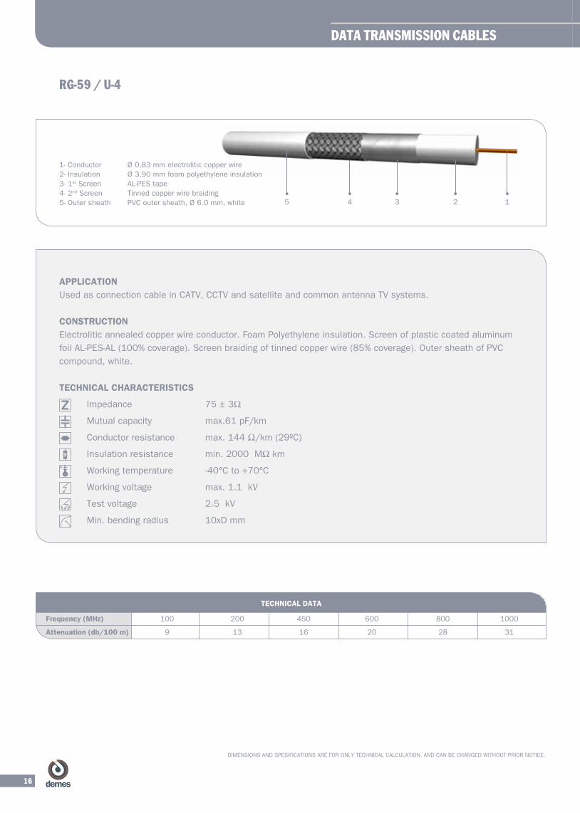
RG-59 / U-4
TECHNICAL DATA
Frequency (MHz) 100 200 450 600 800 1000
Attenuation (db/100 m) 9 13 16 20 28 31
APPLICATIONUsed as connection cable in CATV, CCTV and satellite and common antenna TV systems.
CONSTRUCTIONElectrolitic annealed copper wire conductor. Foam Polyethylene insulation. Screen of plastic coated aluminum
foilAL-PES-AL(100%coverage).Screenbraidingoftinnedcopperwire(85%coverage).OutersheathofPVC
compound, white.
TECHNICAL CHARACTERISTICS
Impedance 75±3Ω
Mutual capacity max.61 pF/km
Conductorresistance max.144Ω/km(29ºC)
Insulationresistance min.2000MΩkm
Working temperature -40°C to +70°C
Working voltage max. 1.1 kV
Test voltage 2.5 kV
Min. bending radius 10xD mm
1- Conductor Ø 0.83 mm electrolitic copper wire2- Insulation Ø 3.90 mm foam polyethylene insulation3- 1st Screen AL-PES tape4- 2nd Screen Tinned copper wire braiding5- Outer sheath PVC outer sheath, Ø 6.0 mm, white 12345
DATA TRANSMISSION CABLES
17
DIMENSIONS AND SPESIFICATIONS ARE FOR ONLY TECHNICAL CALCULATION, AND CAN BE CHANGED WITHOUT PRIOR NOTICE.
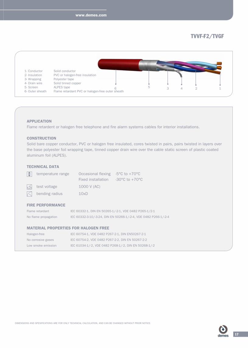
TVVF-F2/TVGF
APPLICATIONFlame retardent or halogen free telephone and fire alarm systems cables for interior installations.
CONSTRUCTION Solid bare copper conductor, PVC or halogen free insulated, cores twisted in pairs, pairs twisted in layers over
the base polyester foil wrapping tape, tinned copper drain wire over the cable static screen of plastic coated
aluminum foil (ALPES).
TECHNICAL DATA
temperature range Occasional flexing -5°C to +70°C
Fixed installation -30°C to +70°C
test voltage 1000 V (AC)
bending radius 10xD
FIRE PERFORMANCEFlame retardant IEC 60332-1, DIN EN 50265-1/-2-1, VDE 0482 P265-1/2-1
No flame propagation IEC 60332-3-10/-3-24, DIN EN 50266-1/-2-4, VDE 0482 P266-1/-2-4
MATERIAL PROPERTIES FOR HALOGEN FREEHalogen-free IEC 60754-1, VDE 0482 P267-2-1, DIN EN50267-2-1
No corrosive gases IEC 60754-2, VDE 0482 P267-2-2, DIN EN 50267-2-2
Low smoke emission IEC 61034-1/-2, VDE 0482 P268-1/-2, DIN EN 50268-1/-2
1- Conductor Solid conductor2- Insulation PVC or halogen-free insulation3- Wrapping Polyester tape4- Drain wire Solid tinned copper5- Screen ALPES tape6- Outer sheath Flame retardant PVC or halogen-free outer sheath
124356
www.demes.com

18
DIMENSIONS AND SPESIFICATIONS ARE FOR ONLY TECHNICAL CALCULATION, AND CAN BE CHANGED WITHOUT PRIOR NOTICE.
TVVF-F2/TVGF
TECHNICAL DATA
Number of cores x Approx. outside diameter (mm) Net weight approx.(kg/km)nominal conductor diameter (mm)
1x2x0.6 4.7 28
2x2x0.6 5.4 39
3x2x0.6 5.8 48
4x2x0.6 6.3 58
5x2x0.6 6.8 68
6x2x0.6 7.2 77
8x2x0.6 7.9 95
10x2x0.6 8.5 113
12x2x0.6 9.1 132
14x2x0.6 9.6 149
15x2x0.6 9.8 157
20x2x0.6 11.4 211
1x2x0.8 5.5 37
2x2x0.8 6.5 55
3x2x0.8 7.2 71
4x2x0.8 7.9 88
5x2x0.8 8.5 104
6x2x0.8 9.1 120
8x2x0.8 10.1 150
10x2x0.8 11.0 179
12x2x0.8 11.8 210
14x2x0.8 12.5 238
15x2x0.8 12.9 252
20x2x0.8 14.8 340
DATA TRANSMISSION CABLES

19
DIMENSIONS AND SPESIFICATIONS ARE FOR ONLY TECHNICAL CALCULATION, AND CAN BE CHANGED WITHOUT PRIOR NOTICE.
TWAVB
APPLICATIONTelephone and signalisation cables, cores twisted in pairs, armoured and flame retardant, for outdoor
installations.
CONSTRUCTION Solid bare copper conductor, Polyethylene insulated, armoured and flame retardant PVC outer sheathed
cables.
TECHNICAL DATA
temperature range Occasional flexing -5°C to +70°C
Fixed installation -30°C to +70°C
FIRE PERFORMANCEFlame retardant IEC 60332-1, DIN EN 50265-1/-2-1, VDE 0482 P265-1/2-1
TECHNICAL DATA
Number of cores x Approx. outside diameter (mm) Net weight approx.(kg/km) nominal conductor diameter (mm)
1x4x0.8 12.0 280
4x2x0.8 14.6 400
5x2x0.8 15.3 440
7x2x0.8 16.2 500
10x2x0.8 18.3 606
12x2x0.8 19.3 681
16x2x0.8 20.2 666
19x2x0.8 21.3 737
21x2x0.8 22.0 782
27x2x0.8 24.0 915
30x2x0.8 25.0 980
40x2x0.8 28.3 1375
52x2x0.8 32.2 1740
61x2x0.8 34.1 1930
80x2x0.8 37.6 2316
100x2x0.8 41.0 3705
1- Conductor Solid bare conductor2- Insulation PE insulation3- Filler Extruded PVC filler4-Armour 2Galvanizedsteeltapewithdrainwireorgalvanizedsteelwires5- Outer Sheath Flame retardant PVC outer sheath
3 124
5
www.demes.com
test voltage 1000 V (AC)
bending radius 15xD

20
DIMENSIONS AND SPESIFICATIONS ARE FOR ONLY TECHNICAL CALCULATION, AND CAN BE CHANGED WITHOUT PRIOR NOTICE.
SVV-F2/SVG-F2
APPLICATIONTelephone and signalisation cables, cores laid up concentric layers and flame retardant, for interior
installations. Halogen free version is SVG-F2.
CONSTRUCTION Solid bare copper conductor, PVC or halogen-free insulated, flame retardant PVC or halogen-free outer
sheathed (low smoke) cables.
TECHNICAL DATA
temperature range Occasional flexing -5°C to +70°C
Fixed installation -30°C to +70°C
test voltage 2500 V (AC)
bending radius 15xD
FIRE PERFORMANCEFlame retardant IEC 60332-1, DIN EN 50265-1/-2-1, VDE 0482 P265-1/2-1
No flame propagation IEC 60332-3-10/-3-24, DIN EN 50266-1/-2-4, VDE 0482 P266-1/-2-4
MATERIAL PROPERTIES FOR HALOGEN FREEHalogen-free IEC 60754-1, VDE 0482 P267-2-1, DIN EN50267-2-1
No corrosive gases IEC 60754-2, VDE 0482 P267-2-2, DIN EN 50267-2-2
Low smoke emission IEC 61034-1/-2, VDE 0482 P268-1/-2, DIN EN 50268-1/-2
1- Conductor Solid bare conductor2- Insulation PVC or halogen-free insulation3- Outer Sheath Flame retardant PVC or halogen-free outer sheath
TECHNICAL DATA
Number of cores x Approx. outside diameter (mm) Net weight approx.(kg/km) nominal conductor diameter (mm)
2x0.8 4.1 21
4x0.8 4.9 37
6x0.8 5.7 51
8x0.8 6.5 68
10x0.8 7.7 91
12x0.8 8.1 108
14x0.8 8.4 122
16x0.8 8.8 136
20x0.8 9.7 164
24x0.8 10.6 193
32 1
DATA TRANSMISSION CABLES

21
DIMENSIONS AND SPESIFICATIONS ARE FOR ONLY TECHNICAL CALCULATION, AND CAN BE CHANGED WITHOUT PRIOR NOTICE.
TPVF-F2/TPGF
APPLICATIONTelephone and signalisation cables, cores twisted in pairs and pairs shielded, flame retardant, for interior
installations. Halogen free version is TPGF.
CONSTRUCTION Solid tinned copper conductor, Polyethylene insulated, flame retardant PVC or halogen-free (low smoke) outer
sheathed cables.
TECHNICAL DATA
temperature range Occasional flexing -5°C to +70°C
Fixed installation -30°C to +70°C
test voltage 1000 V (AC)
bending radius 10xD
FIRE PERFORMANCEFlame retardant EC 60332-1, DIN EN 50265-1/-2-1, VDE 0482 P265-1/2-1
No flame propagation IEC 60332-3-10/-3-24, DIN EN 50266-1/-2-4, VDE 0482 P266-1/-2-4
MATERIAL PROPERTIES FOR HALOGEN FREEHalogen-free IEC 60754-1, VDE 0482 P267-2-1, DIN EN50267-2-1
No corrosive gases IEC 60754-2, VDE 0482 P267-2-2, DIN EN 50267-2-2
Low smoke emission IEC 61034-1/-2, VDE 0482 P268-1/-2, DIN EN 50268-1/-2
1- Conductor Solid tinned conductor2- Insulation PE insulation3- Pairs Screened twisted pairs4- Cable Base Pairs twisted in layers5- Drain Solid tinned copper wire6- Wrapping Polyester tape7- Outer Sheath Flame retardant PVC or halogen free outer sheath
1X2X0.6 5.0 26
2X2X0.6 6.0 38
3X2X0.6 6.5 49
4X2X0.6 7.2 59
6X2X0.6 8.3 78
8X2X0.6 9.0 97
10X2X0.6 10.3 126
12X2X0.6 11.0 145
15X2X0.6 12.0 172
20X2X0.6 13.4 217
26X2X0.6 14.8 270
30X2X0.6 15.7 305
50X2X0.6 19.8 495
1X2X0.8 6.2 42
2X2X0.8 7.4 63
3X2X0.8 8.5 82
4X2X0.8 9.3 101
5X2X0.8 10.0 18
6X2X0.8 10.5 135
8X2X0.8 11.5 169
10X2X0.8 13.0 216
12X2X0.8 14.0 251
15X2X0.8 15.3 302
20X2X0.8 17.3 384
26X2X0.8 19.5 491
30X2X0.8 20.7 555
50X2X0.8 26.2 898
Approx. outside diameter (mm)
Approx. outside diameter (mm)
Net weight approx.(kg/km)
Net weight approx.(kg/km)
Number of cores x nominal conductor diameter (mm)
Number of cores x nominal conductor diameter (mm)
TECHNICAL DATA
3452
1
www.demes.com

22
1245 3
VVT-F2/GGT-F2
APPLICATIONTelephone and signalisation cables, twisted pairs laid up concentric layers with insulated earth wire and flame
retardant, for interior installations. Halogen free version is GGT-F2.
CONSTRUCTION Solid tinned copper conductor, PVC or halogen-free insulated, flame retardant PVC or halogen-free outer
sheathed (low smoke) cables.
TECHNICAL DATA
temperature range Occasional flexing -5°C to +70°C
Fixed installation -30°C to +70°C
test voltage 1000 V (AC)
bending radius 20xD
FIRE PERFORMANCEFlame retardant IEC 60332-1, DIN EN 50265-1/-2-1, VDE 0482 P265-1/2-1
No flame propagation IEC 60332-3-10/-3-24, DIN EN 50266-1/-2-4, VDE 0482 P266-1/-2-4
MATERIAL PROPERTIES FOR HALOGEN FREEHalogen-free IEC 60754-1, VDE 0482 P267-2-1, DIN EN50267-2-1
No corrosive gases IEC 60754-2, VDE 0482 P267-2-2, DIN EN 50267-2-2
Low smoke emission IEC 61034-1/-2, VDE 0482 P268-1/-2, DIN EN 50268-1/-20268-1/-2
1- Conductor Solid tinned conductor2- Insulation PVC or halogen-free insulation3- Earth Wire PVC or halogen-free insulated solid tinned copper4- Wrapping Tape Polyester tape5- Outer Sheath Flame retardant PVC or halogen-free outer sheath
DATA TRANSMISSION CABLES

23
VVT-F2/GGT-F2
TECHNICAL DATA
Number of cores x Approx. outside diameter (mm) Net weight approx.(kg/km)nominal contuctor diameter (mm2)
1x2x0.6 5.0 27
2x2x0.6 5.6 37
3x2x0.6 6.2 46
4x2x0.6 6.7 55
6x2x0.6 7.5 72
8x2x0.6 8.2 88
10x2x0.6 8.8 111
12x2x0.6 9.4 127
14x2x0.6 9.9 143
20x2x0.6 11.2 190
26x2x0.6 12.6 245
30x2x0.6 13.2 275
40x2x0.6 15.0 358
50x2x0.6 16.5 435
100x2x0.6 22.5 850
www.demes.com

24
APPLICATIONThese cables are used in professional broadcasting systems for the transmission of analogue audio signals.
CONSTRUCTION The cable consists of stranded multiwire copper conductors and PVC insulated according to BS EN 60228
standard.
TECHNICAL DATA
Type Nominal cable dimension (Thicknessx width) (mm)
MAX. conductor Weight resistance (Ohm/km) (kg/km)
2x0.35 1.60x3.2 53.0 5.0
2x0.50 1.90x3.8 39.0 7.5
2x0.75 2.10x4.2 26.0 8.5
2x1.00 2.30x4.6 19.5 9.5
2x1.50 2.55x5.1 13.3 11.0
2x2.50 3.00x6.0 8.0 13.0
2x4.00 3.50x7.1 5.0 16.0
2x6.00 4.30x8.5 3.3 23.0
LOUD SPEAKER
12
DATA TRANSMISSION CABLES
1- Conductor Fine stranded copper conductor2- Insulation PVC insulation

25
Technical Data
Units of ForceEnglish gravitational systems: pound-force 1 lbf = 1 LbEnglishabsolutesystems: poundal1pdl=1lb•ft/s²1lbf=32.174pdl–9.80665lb•m/s²
Conversion to metric units 1 pound-force (lbf) = 0.454 kp1 Brit. ton –force = 1016 kp1 poundal (pdl) = 0.1383 N1 lbf = 4.445 N
Electrical units per unit lenght Density1 μf per mile =0.62μF/km 1 lb/ft3 = 16.02 kg/m³1megohmpermile=1.61MΩ•km1 decibel per mile = 71.5 m/N/km Weight (specific weight) 1 μf per foot =3.28 pF/m 1 lbf/ft3 = 16.02 kp/m³1 decibel per 100 ft =3.77 N/km1ohmper1000ft=3.28Ω/km Copper wire weight per mile 1ohmper1000yd=1.0936Ω/km lb/mile Ømm 5 0.404Weight per unit lenght 6.5 0.511 lb per foot = 1.488 kg/m 7.5 0.551 lb per yard = 0.469 kg/m 10 0.641 lb per mile = 0.282 kg/m 20 0.90 40 1.27Units of Energy1 horsepower = 0.746 kW (H.P.)1 brit. therm unit = 0.252 kcal
The insulation wall thicknesses are often expressed in n/64 inches, 1.64 inch being rougly equal to 0.4 mm
Further dimensions for wire weights and for electrical field strengths:
lbf pr. MFeet = 1.488 kg/km 40 V/mil =1.6 kV/mmlbf pr. Mile = 0.282 kg/km 80V/mil = 3.2 kV/mm 100V/mil =4.0 kV/mm 250V/mil =10.0 kV/mm
British and US Dimensions for Cable and Leads
AWG Diameter Cross-section Conductor resistance No. mm mm² Ω/km
500 17.96 253 0.07
350 15.03 177 0.10
250 12.70 127 0.14
4/0 11.68 107.2 0.18
3/0 10.40 85.0 0.23
2/0 9.27 67.5 0.29
1/0 8.25 53.5 0.37
1 7.35 42.4 0.47
2 6.54 33.6 0.57
4 5.19 21.2 0.91
6 4.12 13.3 1.44
8 3.26 8.37 2.36
10 2.59 5.26 3.64
12 2.05 3.31 5.41
14 1.63 2.08 8.79
AWG Diameter Cross-section Conductor resistance No. mm mm² Ω/km
16 1.29 1.33 14.7
18 1.204 0.823 23.0
20 0.813 0.519 34.5
22 0.643 0.324 54.8
24 0.511 0.205 89.2
26 0.405 0.128 149
28 0.320 0.0804 232
30 0.255 0.0507 350
32 0.203 0.0324 578
34 0.160 0.0200 899
36 0.127 0.0127 1426
38 0.102 0.00811 2255
40 0.079 0.00487 3802
42 0.064 0.00317 5842
44 0.051 0.00203 9123
General Dimensions
In the US area of influence the dimensions of copper conductors for power and data transmission purposes are usuallyexpressed in AWG Nos*. The corresponding values are:
The basic units are in the English gravitational system Lenght (ft)-force (lbf=Lb)-time (s)in the English obsolute system Lenght (ft)-mass (lb)-time (s)
Lenght Dimensions Cubic Dimensions 1 ml =0.0254 mm 1 cubic inch =16.39 cm³1 inch (in, “) =25.4 mm 1 cubic foot = 0.0283 cm³1foot(ft,“)=0.305m 1cubicyard=0.765mm²1 yard (yd) = 0.914 m 1 US liquid galon = 3.7911 chain (ch) =20.1 m 1 pint = 0.47311 statue mile = 1.61 km 1 quart = 0.94611 nautical mile = 1.835 km 1 brit gallon =4.5311 statue mile = 1760 yards 1 barrel = 119.21
Area Dimensions1circ.mil(CM) =0.507•10¯³mm²1MCM =0.5067mm²1squareinch(sg.in.) =645.16mm²1squarefoot(sq.ft.) =0.0929m²1squareyard =0.836m²1acre =0.00405km²1squaremile =2.59km²1m2 = 10.764 sq. ft.
Mass Units Englishgravitationsystem 1slug=1lbs•s²/ftEnglish 1 pound = 1 lb1slug=32.174lb,with32.174ft/s²asthestandardvalueofac-celeration due to grativity.
Conversion to metric units1 grain = 64.80 mg1 dram = 1.770 g1ounce(oz)=16drams=28.35g1pound(lb)=16oz =453.59g1 stone = 14 lbs = 6.35 kg1 US ton (short ton) = 0.907 t1 Brit. Ton (long ton) = 1.016 t
www.demes.com

26
Drum Capacities for Plastic-Insulated Cable in Metres to DIN 46 391
DrumNo Drumsize d1 d2 d4 L1 L4 kg kg
061 06 630 315 56 415 315 250 17
071 07 710 355 80 525 400 400 27
081 08 800 400 80 525 400 600 33
091 09 900 450 80 685 560 800 46
101 10 1000 500 80 685 560 900 57
121 12 1250 630 80 870 666 1700 119
141 14 1400 710 80 870 660 2000 154
161 16/8 1600 800 80 1100 844 3000 254
162 16/10 1600 1000 80 1100 835 3000 269
181 18/10 1800 1000 100 1100 835 4000 334
182 18/12 1800 1250 100 1100 825 4000 352
201 20/12 2000 1250 100 1345 1345 5000 524
202 20/14 2000 1400 100 1345 1035 5000 524
221 22/14 2240 1400 125 1475 1140 6000 704
222 22/16 2240 1600 125 1475 1130 6000 738
250 25/14 2500 1600 125 1475 1140 7500 839
251 25/16 2500 1600 125 1475 1130 7500 872
252 25/18 2500 1800 125 1475 1120 7500 909
281 28/18 2800 1800 140 1635 1280 10000 1121
282 28/20 2800 2000 140 1635 1270 10000 1166
61 1113 472 253 179 93 - - -
71 2024 892 468 297 165 - - -
81 2755 1152 643 430 219 151 - -
91 - 2202 1206 749 402 285 162 -
101 - - 1540 1000 576 365 220 -
121 - - - 1991 1139 688 450 249
141 - - - 2479 1352 839 564 327
161 - - - - 2435 1608 1025 549 319
181 - - - - - 1867 1197 640 373 246
201 - - - - - 2522 1583 812 558 296 163
221 - - - - - - 2383 1328 678 566 278
250 - - - - - - - 2892 1107 699 363
6 9 12 15 20 25 30 40 50 60 80
CablesReel
TYPE Diameter in mm Width in mm Max. load Weight
DATA TRANSMISSION CABLES

27
DIN 47100 Colour Codes
The colour code for DEMTRONIK and DEMFLEKS cables is in accordance with DIN 47100/Nov. 1979. In each pair there is always oneA-core and one B-core. Upwards of 23 pairs, the identification repeats itself for the first time and from 45 pairs fort he second time. The first is always the basic colour of the core and the second colour is applied in ring-form.
No of Pairs Colour a-core Colour b-core No of Pairs Colour a-core Colour b-core
1 white brown 13 white/black brown/black2 green yellow 14 grey/green yellow/grey3 grey pink 15 pink/green yellow/pink4 blue red 16 green/blue yellow/blue5 black violet 17 green/red yellow/red 6 grey/pink red/blue 18 green/black yellow/ black7 white/green brown/green 19 grey/blue pink/blue8 white/yellow yellow/brown 20 grey/red pink/red9 white/grey grey/brown 21 grey/black pink/black10 white/pink pink/brown 22 blue/black red/black11 white/blue brown/blue 23-44 see above see above12 white/red brown/red 45-66 see above see above
The core insulation gives the first colour –the second colour is provided by a coloured ringing or band. Where three colours are specified the second and third colours are printed alternately over the basic colour (1 st colour).
1 white 22 brown/ blue 43 blue/black
2 brown 23 white/red 44 red/black
3 green 24 brown/red 45 white/brown/black
4 yellow 25 white/black 46 yellow/green/black
5 grey 26 brown/black 47 grey/pink/black
6 pink 27 grey/green 48 red/blue/black
7 blue 28 yellow/grey 49 white/green/black
8 red 29 pink/green 50 brown/green/black
9 black 30 yellow/pink 51 white/yellow/black
10 violet 31 green/blue 52 yellow/brown/black
11 grey/pink 32 yellow/blue 53 white/grey/black
12 red/blue 33 green/red 54 grey/brown/black
13 white/green 34 yellow/red 55 white/pink/black
14 brown/green 35 green/black 56 pink/brown/black
15 white/yellow 36 yellow/black 57 white/blue/black
16 yellow/brown 37 grey/blue 58 brown/blue/black
17 white/grey 38 pink/blue 59 white/red/black
18 grey/brown 39 grey/red 60 brown/red/black
19 white/pink 40 pink/red 61 black/white
20 pink/brown 41 grey/black
21 white/blue 42 pink/black
DIN 47100 Colour Codes (without colour repetition)
LAN (Local area network)
a-wire pair nr. b-wire
white-blue 1 blue white-orange 2 orange white-green 3 green white-brown 4 brown
www.demes.com

28
TECHNICAL DATA
CAT2 CAT3 CAT4 CAT5 Frequency Attenuation Next Attenuation Next Attenuation Next Attenuation Next MHz dB/100m(max) dB(min) dB/100m (max) dB (min) dB/100m (max) dB (min) dB/100m (max) dB (min)
0.772 2.2 - 2.2 43 1.9 58 1.8 64
1 2.6 - 2.6 41 2.2 56 2.0 62
4 - - 5.6 32 4.3 47 4.1 53
8 - - 8.5 27 6.2 42 5.8 48
10 - - 9.7 26 6.9 41 6.5 47
16 - - 13.1 23 8.9 38 8.2 44
20 - - - - 10.0 36 9.3 42
25 - - - - - - 10.4 41
31.25 - - - - - - 11.7 39
62.5 - - - - - - 17.0 35
100 - - - - - - 22.0 32
CODE DESIGNATION ACCORDING TO VDE
ACR Attenuation to Crosstalk Ratio
BD Building Entrance Facilities
BFOC Bayonet Fibre Optic Connector
B-ISDN Broadband ISDN
BRI Basic Rate ISDN
CD Campus Distributor
c Speed of light
CISPR International Special Committee on Radio Interference
CSMA/CD Carrier Sence Miltiple Access with Collision Detection
DCE Data Circuit Terminating Equipment
DTE Data Terminal Equipment
DUT Device Under Test
EMC Electromagnetic Compability
EMI Electromagnetic Interference
ER Equipment Room
FD Floor Distributor
FDDI Fibre Distributed Data Interface
FOIRL Fibre Optic Inter-Repeater Link
FWHM Full Width Half Maximum
IC Integrated Circuit
IDC Insulation Displacement Connection
IEC International Electrotechnical Commission
ISDN Integrated Services Digital Network
ISO InternationalOrganisationforStandardization
ITU-T International Telecommunication Union
TelecommunicationStandardizationBureau(formerlyCCITT)
JTC Join Technical Commitee
LAN Local Area Network
LCL Longitudinal Conversion Loss
LCTL Longitudinal Conversion Transfer Loss
N/A Not Applicable
N-BNC N type to BNC Convertor
NEXT Near And Crosstalk
OTDR Optical Time Domain Reflectometer
PBX Private Branch Exchange
PDAM Proposed Draft Amendment
PMD Physical Layer Medium Dependent
SC Subsscriber Connector (Optical fibre connector)
SC-D Duplex SC connector
STI Surface Transfer Impedance
TC Telecommunications Closet
TDR Time Domain Reflectometer
TO Telecommunications Outlet
TP Transition Point
Network Structure
Ring Star Bus Mesh Tree
Cable level Data speed
1 ve 2 Ses Frekans Sistemleri
3 ≤10MBit/s
4 ≤16MBit/s
5 ≤100MBit/s
6 ≤300MBit/s
DATA TRANSMISSION CABLES www.demes.com

NOTE

NOTE
NOTE

NOTE


Kıraç Bel. 3. Bölge Feyzi Çakmak Cd. No: 56 B. Çekmece - İSTTelefon: +90 212 689 49 00/Pbx Faks: +90 212 689 00 17www.demes.com
DEMES KABLO SAN. TİC. LTD. ŞTİ