UTILITY FLIGHT MANUAL X-15-1 FLIGHT MANUAL Desktop commanders are responsible for bringing this...
15
UTILITY FLIGHT MANUAL Desktop commanders are responsible for bringing this publication to the attention of all flight simulator enthusiasts and X-15 fans cleared for operation of subject add- on rocket aircraft. Contains full product description and speci- fications, installation instructions, normal procedures and check list. X-15-1 ADD-ON ROCKET AIRCRAFT FOR FLIGHT SIMULATOR Serial number: AF56-6670 (XLR-11 and XLR-99 engines) ENGLISH VERSION 1.0 X-15 FOR FLIGHT SIMULATOR SERIES treme Prototypes X www.xtremeprototypes.com XP-X151-1E
Transcript of UTILITY FLIGHT MANUAL X-15-1 FLIGHT MANUAL Desktop commanders are responsible for bringing this...

UTILITY FLIGHT MANUAL
Desktop commanders are responsible for bringing this publication to the attention of all flight simulator enthusiasts and X-15 fans cleared for operation of subject add-on rocket aircraft. Contains full product description and speci-fications, installation instructions, normal procedures and check list.
X-15-1 ADD-ON ROCKET AIRCRAFT
FOR FLIGHT SIMULATOR
Serial number: AF56-6670 (XLR-11 and XLR-99 engines)
ENGLISH VERSION 1.0
X-15 FOR FLIGHT SIMULATOR SERIES
treme Prototypes X
www.xtremeprototypes.com
XP-X151-1E

Xtreme Prototypes X-15-1 for Flight Simulator, Version 1.0 – Utility Flight Manual 3
FOREWORD 4
Section INTRODUCTION AND PRODUCT DESCRIPTION 1-1
Section SOFTWARE INSTALLATION 2-1
Section AIRCRAFT DESCRIPTION AND SPECIFICATIONS 3-1
Section INSTRUMENT PANELS 4-1
Section NORMAL PROCEDURES AND CHECK LIST 5-1
Section CONDENSED PROCEDURES AND CHECK LIST 6-1
APPENDICES Appendix 1: QUICK-START PROCEDURES A-1
Appendix 2: INSTRUMENT READINGS A-2
Appendix 3: FS AIRCRAFT REFERENCE INFORMATION A-3
Appendix 4: PRODUCT SPECIFICATIONS A-4
Appendix 5: SELECTED INTERNET LINKS A-5
Appendix 6: SELECTED BIBLIOGRAPHY A-6
Appendix 7: OTHER X-15 FOR FLIGHT SIMULATOR PRODUCTS by Xtreme Prototypes A-7
TABLE OF CONTENTS
I II III IV V VI

Xtreme Prototypes X-15-1 for Flight Simulator Version 1.0 – Utility Flight Manual 3-4
X-15-1 (BOOM NOSE, XLR-11 ENGINES, “CLEAN” ROLLOUT VERSION)
23 24 3 4 1 13 5 2 7 8 25 26 9 27 28 11
29 30 31 32 33 15 14 16 34 17 18 19 21 22 12
1 2 3 4 5 6 7 8 9 10 12
13 14 15 16 17 18 19 20 21 22
11
1. MOVABLE HORIZONTAL STABILIZER 2. BALLISTIC CONTROL SYSTEM ROCKETS (2,
ON BOTH WINGS) 3. UPPER SPEED BRAKE 4. MOVABLE UPPER VERTICAL STABILIZER 5. LIQUID OXYGEN TANK (FROST) 6. APU EXHAUST (2, LEFT AND RIGHT) 7. UPPER UHF ANTENNA 8. TOP BUG-EYE CAMERA PORT (2, ON BOTH
SIDES) 9. CANOPY 10. PITOT HEAD 11. BALLISTIC CONTROL SYSTEM ROCKETS (8) 12. NACA VANE-TYPE BOOM NOSE
13. WING (2, LEFT AND RIGHT) 14. REAR LANDING GEAR SKID (2, ON BOTH
SIDES) 15. LOWER SPEED BRAKE 16. LOWER FIXED VERTICAL STABILIZER
(MOVABLE VENTRAL REMOVED) 17. VENTRAL BUG-EYE CAMERA PORT (2, ON
BOTH SIDES) 18. SIDE FAIRING (2, LEFT AND RIGHT) 19. LOWER UHF ANTENNA 20. EXTERNAL CANOPY EMERGENCY JETTISON
HANDLE ACCESS DOOR 21. NOSE LANDING GEAR DOOR 22. NOSE LANDING GEAR
23. UPPER XLR-11 ENGINE TURBOPUMP EX-HAUST
24. UPPER XLR-11 ROCKET ENGINE 25. EQUIPMENT COMPARTMENT 26. EJECTION SEAT 27. PILOT 28. INSTRUMENT PANEL 29. LIQUID OXYGEN JETTISON PORT 30. LOWER XLR-11 ENGINE TURBOPUMP EX-
HAUST 31. LOWER XLR-11 ROCKET ENGINE 32. WATER-ALCOHOL JETTISON PORT 33. HYDROGEN PEROXIDE JETTISON PORT 34. FLAP (2, LEFT AND RIGHT)
Figure 3-1
GENERAL ARRANGEMENT
Xtreme Prototypes X-15-1 for Flight Simulator, Version 1.0 – Utility Flight Manual 4-2
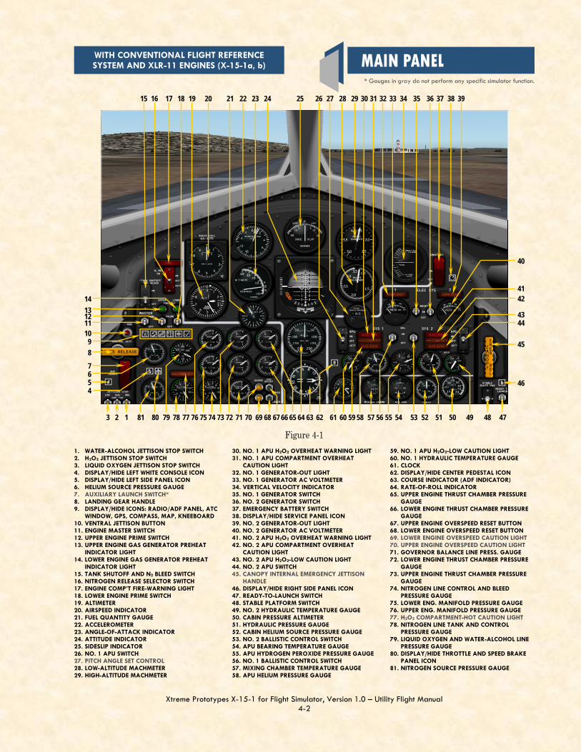
WITH CONVENTIONAL FLIGHT REFERENCE SYSTEM AND XLR-11 ENGINES (X-15-1a, b)
1. WATER-ALCOHOL JETTISON STOP SWITCH 2. H2O2 JETTISON STOP SWITCH 3. LIQUID OXYGEN JETTISON STOP SWITCH 4. DISPLAY/HIDE LEFT WHITE CONSOLE ICON 5. DISPLAY/HIDE LEFT SIDE PANEL ICON 6. HELIUM SOURCE PRESSURE GAUGE 7. AUXILIARY LAUNCH SWITCH* 8. LANDING GEAR HANDLE 9. DISPLAY/HIDE ICONS: RADIO/ADF PANEL, ATC
WINDOW, GPS, COMPASS, MAP, KNEEBOARD 10. VENTRAL JETTISON BUTTON 11. ENGINE MASTER SWITCH 12. UPPER ENGINE PRIME SWITCH 13. UPPER ENGINE GAS GENERATOR PREHEAT
INDICATOR LIGHT 14. LOWER ENGINE GAS GENERATOR PREHEAT
INDICATOR LIGHT 15. TANK SHUTOFF AND N2 BLEED SWITCH 16. NITROGEN RELEASE SELECTOR SWITCH 17. ENGINE COMP’T FIRE-WARNING LIGHT 18. LOWER ENGINE PRIME SWITCH 19. ALTIMETER 20. AIRSPEED INDICATOR 21. FUEL QUANTITY GAUGE 22. ACCELEROMETER 23. ANGLE-OF-ATTACK INDICATOR 24. ATTITUDE INDICATOR 25. SIDESLIP INDICATOR 26. NO. 1 APU SWITCH 27. PITCH ANGLE SET CONTROL 28. LOW-ALTITUDE MACHMETER 29. HIGH-ALTITUDE MACHMETER
30. NO. 1 APU H2O2 OVERHEAT WARNING LIGHT 31. NO. 1 APU COMPARTMENT OVERHEAT
CAUTION LIGHT 32. NO. 1 GENERATOR-OUT LIGHT 33. NO. 1 GENERATOR AC VOLTMETER 34. VERTICAL VELOCITY INDICATOR 35. NO. 1 GENERATOR SWITCH 36. NO. 2 GENERATOR SWITCH 37. EMERGENCY BATTERY SWITCH 38. DISPLAY/HIDE SERVICE PANEL ICON 39. NO. 2 GENERATOR-OUT LIGHT 40. NO. 2 GENERATOR AC VOLTMETER 41. NO. 2 APU H2O2 OVERHEAT WARNING LIGHT 42. NO. 2 APU COMPARTMENT OVERHEAT
CAUTION LIGHT 43. NO. 2 APU H2O2-LOW CAUTION LIGHT 44. NO. 2 APU SWITCH 45. CANOPY INTERNAL EMERGENCY JETTISON
HANDLE 46. DISPLAY/HIDE RIGHT SIDE PANEL ICON 47. READY-TO-LAUNCH SWITCH 48. STABLE PLATFORM SWITCH 49. NO. 2 HYDRAULIC TEMPERATURE GAUGE 50. CABIN PRESSURE ALTIMETER 51. HYDRAULIC PRESSURE GAUGE 52. CABIN HELIUM SOURCE PRESSURE GAUGE 53. NO. 2 BALLISTIC CONTROL SWITCH 54. APU BEARING TEMPERATURE GAUGE 55. APU HYDROGEN PEROXIDE PRESSURE GAUGE 56. NO. 1 BALLISTIC CONTROL SWITCH 57. MIXING CHAMBER TEMPERATURE GAUGE 58. APU HELIUM PRESSURE GAUGE
59. NO. 1 APU H2O2-LOW CAUTION LIGHT 60. NO. 1 HYDRAULIC TEMPERATURE GAUGE 61. CLOCK 62. DISPLAY/HIDE CENTER PEDESTAL ICON 63. COURSE INDICATOR (ADF INDICATOR) 64. RATE-OF-ROLL INDICATOR 65. UPPER ENGINE THRUST CHAMBER PRESSURE
GAUGE 66. LOWER ENGINE THRUST CHAMBER PRESSURE
GAUGE 67. UPPER ENGINE OVERSPEED RESET BUTTON 68. LOWER ENGINE OVERSPEED RESET BUTTON 69. LOWER ENGINE OVERSPEED CAUTION LIGHT 70. UPPER ENGINE OVERSPEED CAUTION LIGHT 71. GOVERNOR BALANCE LINE PRESS. GAUGE 72. LOWER ENGINE THRUST CHAMBER PRESSURE
GAUGE 73. UPPER ENGINE THRUST CHAMBER PRESSURE
GAUGE 74. NITROGEN LINE CONTROL AND BLEED
PRESSURE GAUGE 75. LOWER ENG. MANIFOLD PRESSURE GAUGE 76. UPPER ENG. MANIFOLD PRESSURE GAUGE 77. H2O2 COMPARTMENT-HOT CAUTION LIGHT 78. NITROGEN LINE TANK AND CONTROL
PRESSURE GAUGE 79. LIQUID OXYGEN AND WATER-ALCOHOL LINE
PRESSURE GAUGE 80. DISPLAY/HIDE THROTTLE AND SPEED BRAKE
PANEL ICON 81. NITROGEN SOURCE PRESSURE GAUGE
Figure 4-1
1 2 3
4 5 6 7 8 9
10 11 12 13 14
15 16 17 18 19 20 21 22 23 24 25 26 27 28 29 30 31 32 33 34 35 36 37 38 39
40
41 42
43 44
45
46
47 48 49 50 51 52 53 54 55 56 57 58 59 60 61 62 63 64 65 66 67 68 69 70 71 72 73 74 75 76 77 78 79 80 81
* Gauges in gray do not perform any specific simulator function.
MAIN PANEL

Xtreme Prototypes X-15-1 for Flight Simulator, Version 1.0 – Utility Flight Manual 5-10
THROTTLE AND SPEED BRAKE PANEL icon [80, fig. 4-1; 25, fig. 4-2; 24, fig. 4-3] on the main panel to dis-play the throttle and speed brake panel (or select THROTTLE AND SPEED BRAKE PANEL from the “Instrument Panel” menu, under the “View” menu of the main Flight Simulator win-dow menu bar).
5. Undock and reposition the panel if necessary.
6. Speed brake handles [9, fig. 4-9] – CLOSED (forward).
7. Click the DISPLAY/HIDE LEFT WHITE CONSOLE icon [4, fig. 4-1; 24, fig 4-2; 23, fig. 4-3] on the main panel to display the left white console panel (or select LEFT WHITE CONSOLE from the “Instrument Panel” menu, under the “View” menu of the main Flight Simulator window menu bar).
8. Undock and repo-sition the panel if necessary.
9. Wing flap switch [1, fig. 4-10] – UP.
10. Jettison trim switch [2, fig. 4-10] – OFF (center).
11. Vent, pressurize, and jettison con-trol lever [3, fig. 4-10] – VENT.
In the real world: The vent valve on the water-alcohol or ammonia tank will be manually closed before flight to prevent losing water-alcohol or ammonia during captive flight (when the X-15 is attached to the NB-52 carrier). When the vent, pressurize, or jettison control lever is placed in the PRESSURIZE or JETTISON position and then back to VENT, the water-alcohol or ammonia vent valve will then be open. 12. Engine thrust selector switches (eight) [1-8, fig. 4-9]
– OFF (aft) (XLR-11 engines only).
13. Throttle [10, fig. 4-9] – OFF (XLR-99 engine only).
14. Click the DISPLAY/HIDE LEFT SIDE PANEL icon [5, fig. 4-1, 4-2; 7, fig. 4-3 ] at the far left of the main panel to dis-play the left side panel (or select LEFT SIDE PANEL from the “Instrument Panel” menu, under the “View” menu of the main Flight Simulator window menu bar).
15. Undock and reposition the panel if necessary.
16. Jettison stop switches [4-6, fig. 4-5] – STOP. Check that all three switches (LOX, H2O2, and WALC or NH3) are in the STOP position.
17. Auxiliary launch switch [3, fig. 4-5] – OFF (guard down).
18. Ventral jettison button [2, fig. 4-5] – Check (normal).
19. Landing gear handle [1, fig. 4-5] – IN. Main instrument panel (XLR-11 engines):
1. Fire-warning (red) light [17, fig. 4-1] – Check OFF.
2. N2 release switch [16, fig. 4-1] – OFF.

Xtreme Prototypes X-15-1 for Flight Simulator, Version 1.0 – Utility Flight Manual 5-15
CAPTIVE TAXI AND FLIGHT 1. Radio function selector switch [3, fig. 4-8] – Turn
right to MIDDLE position (Main, T/R; Aux., ADF).
NOTE: The radio function selector switch [3, fig. 4-8] must stay in this (middle) position or be turned further right for the simulator’s GPS to be turned on. Turning this switch to OFF (in the left position) turns off the air-craft’s avionics and the GPS. See page 5-25-26. TAXI (CARRIER AIRPLANE) In the real world: The following procedures were done during taxi and before takeoff of the carrier airplane. 1. SAS function
switches and (amber) lights [1-4, 5-6, 31-32, fig. 4-11; 1-4, 5-6, 15-16, fig. 4-13] – Check. Move SAS func-tion switches to
ENGAGE or LO GAIN and check lights (should come OFF). Re-turn function switches to STDBY after each function trips.
2. Radar beacon switch [22, fig. 4-11; 13, fig. 4-12] – ON.
BEFORE TAKEOFF (CARRIER AIRPLAINE) In the real world: The following procedures were done before takeoff of the carrier airplane. 1. Ram-air lever [28, fig. 4-11; 15, fig. 4-12] –
CLOSED.
2. N2 or helium release switch [16, fig. 4-1; 10, fig. 4-2; 17, fig. 4-3] – AUTO.
3. Jettison stop switches [1-3, fig. 4-1, 4-2, 4-3; 4-6, fig. 4-5] – STOP.
XLR-11 engines: In the real world: The X-15 pilot would check and report on the following instruments. 1. Cabin source pressure gauge [52, fig. 4-1] – Check
(2800 to 3900 psi).
2. Helium source pressure gauge [6, fig. 4-1] – Check (3300 to 3800 psi).
3. N2 source pressure gauge [81, fig. 4-1] – Check (No. 1, 3200 to 3900 psi; No. 2, 2900 to 3900 psi).
XLR-99 engine: In the real world: The X-15 pilot would check and report the following instruments. 1. Propellant source pressure gauge [12, fig. 4-2; 13,
fig. 4-3] – Check (3300 to 3800 psi).
2. Propellant tank pressure gauge [6, fig. 4-2; 81, fig. 4-3] – Check (pointer "L", 0 to 5 psi; "A", 0 to 10 psi).
3. Propellant pump inlet pressure gauge [8, fig. 4-2; 74,
X-15-1 for Flight Simulator after servicing.

Xtreme Prototypes X-15-1 for Flight Simulator, Version 1.0 – Utility Flight Manual 5-19
(right side). Because of some limitations of the FS2004 platform, the H2O2 jettison effect cannot be observed in the X-15-1 equipped with the XLR-11 engines. For the same reason, there is no special effect associated with the APU H2O2 jettison. Propellant tank pressuri-zation: 1. Vent, pressurize,
and jettison control lever [3, fig. 4-10] – PRESSURIZE.
When the vent, pressur-ize, and jettison control lever is moved to PRES-SURIZE, water-alcohol (or ammonia) and liquid oxygen tanks are pressurized and the propellants will be supplied to the engine turbopump(s). The hydrogen perox-ide tank is also pressurized and H2O2 will be supplied to the turbopump(s) cut-off valve(s). In the real world: The X-15 pilot would check and report the following instruments. If instruments are not within limits, the pilot would check with ground control for an alternate mission. XLR-11 engines: 1. Water-alcohol and liquid oxygen line pressure gauge
[79, fig. 4-1] – Check ("L" pointer, 45 to 65 psi; "A" pointer, 43 to 70 psi).
2. N2 line, tank and control pressure gauge [78, fig. 4-1] – Check (“C” pointer, 475 to 575 psi; “T” pointer, 425 to 475 psi).
3. Engine preheat (green) lights [13-14, fig. 4-1] – Check ON (after a short delay).
XLR-99 engine: 1. Propellant tank pressure gauge [6, fig. 4-2; 81, fig. 4-
3] – Check ("L" pointer, 45 to 65 psi; "A" pointer, 45 to 65 psi).
2. H2O2 tank and engine control line pressure gauge [86, fig. 4-2; 79, fig. 4-3] – Check (“C” pointer, 575 to 615 psi; “T” pointer, 425 to 475 psi).
eration, driving rapidly to indicate the actual angle of attack and sideslip of the airplane. Propellant jettison tests: Propellant jettison tests will be conducted concurrently on all three systems (liquid oxygen, water-alcohol or am-monia and hydrogen peroxide). 1. Instrument readings – Check for proper reading
before pressurization.
2. Vent, pressurize, and jettison control lever [3, fig. 4-10] – JETTI-SON.
3. Jettison stop switches [4-6, fig. 4-5] – JETT for about 3 seconds then STOP. In the spot plane exterior view, check for vapor emitting from the jetti-son ports, at the back of the X-15 aircraft.
NOTE: The liquid oxygen and water-alcohol or ammo-nia jettison ports are the long tubes protruding at the back of the airplane’s side fairings (each side of the en-gine compartment). The hydrogen peroxide jettison port is located inside the lower speed brake compartment
The three propellants (liquid oxygen, ammonia and hydro-gen peroxide) are being dumped overboard through the jettison ports at the back of the X-15-1 for Flight Simula-
tor.
Xtreme Prototypes X-15-1 for Flight Simulator, Version 1.0 – Utility Flight Manual 5-20
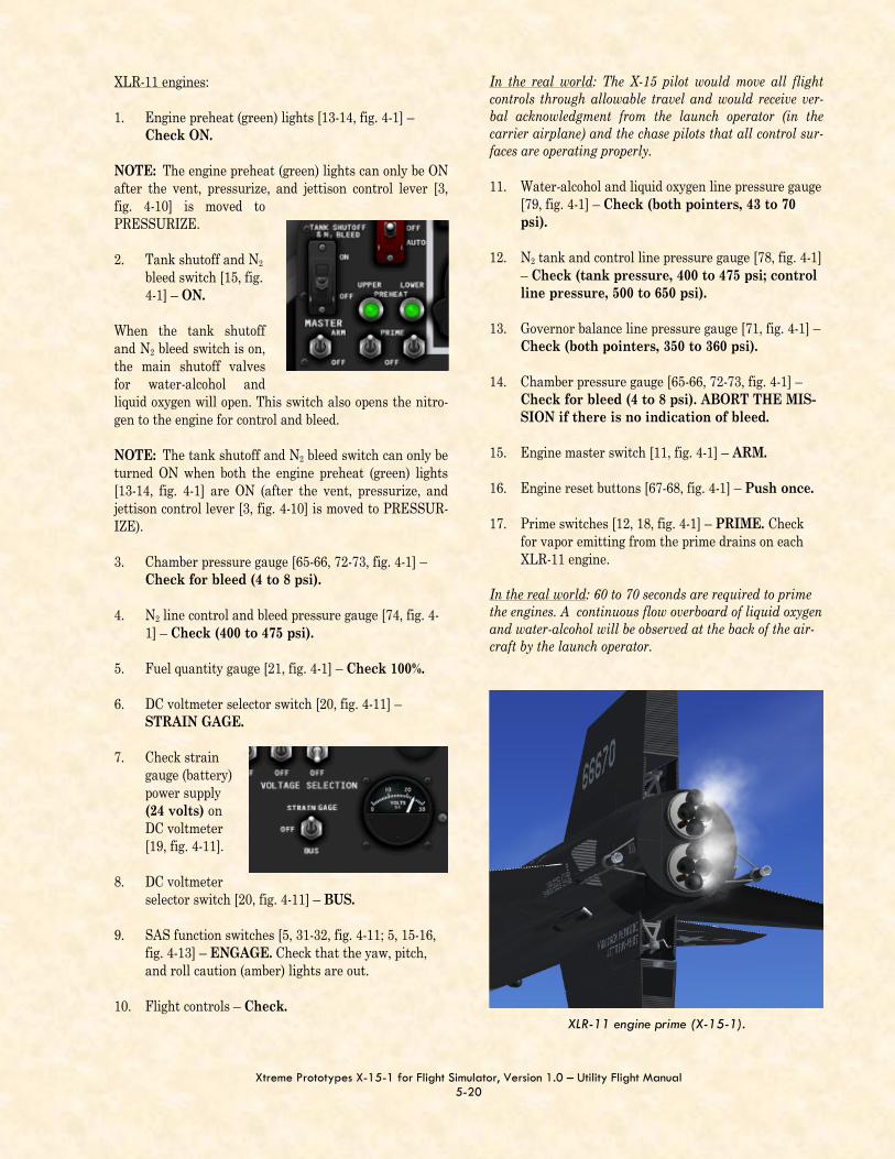
XLR-11 engines: 1. Engine preheat (green) lights [13-14, fig. 4-1] –
Check ON. NOTE: The engine preheat (green) lights can only be ON after the vent, pressurize, and jettison control lever [3, fig. 4-10] is moved to PRESSURIZE. 2. Tank shutoff and N2
bleed switch [15, fig. 4-1] – ON.
When the tank shutoff and N2 bleed switch is on, the main shutoff valves for water-alcohol and liquid oxygen will open. This switch also opens the nitro-gen to the engine for control and bleed. NOTE: The tank shutoff and N2 bleed switch can only be turned ON when both the engine preheat (green) lights [13-14, fig. 4-1] are ON (after the vent, pressurize, and jettison control lever [3, fig. 4-10] is moved to PRESSUR-IZE). 3. Chamber pressure gauge [65-66, 72-73, fig. 4-1] –
Check for bleed (4 to 8 psi).
4. N2 line control and bleed pressure gauge [74, fig. 4-1] – Check (400 to 475 psi).
5. Fuel quantity gauge [21, fig. 4-1] – Check 100%.
6. DC voltmeter selector switch [20, fig. 4-11] – STRAIN GAGE.
7. Check strain gauge (battery) power supply (24 volts) on DC voltmeter [19, fig. 4-11].
8. DC voltmeter selector switch [20, fig. 4-11] – BUS.
9. SAS function switches [5, 31-32, fig. 4-11; 5, 15-16, fig. 4-13] – ENGAGE. Check that the yaw, pitch, and roll caution (amber) lights are out.
10. Flight controls – Check.
In the real world: The X-15 pilot would move all flight controls through allowable travel and would receive ver-bal acknowledgment from the launch operator (in the carrier airplane) and the chase pilots that all control sur-faces are operating properly. 11. Water-alcohol and liquid oxygen line pressure gauge
[79, fig. 4-1] – Check (both pointers, 43 to 70 psi).
12. N2 tank and control line pressure gauge [78, fig. 4-1] – Check (tank pressure, 400 to 475 psi; control line pressure, 500 to 650 psi).
13. Governor balance line pressure gauge [71, fig. 4-1] – Check (both pointers, 350 to 360 psi).
14. Chamber pressure gauge [65-66, 72-73, fig. 4-1] – Check for bleed (4 to 8 psi). ABORT THE MIS-SION if there is no indication of bleed.
15. Engine master switch [11, fig. 4-1] – ARM.
16. Engine reset buttons [67-68, fig. 4-1] – Push once.
17. Prime switches [12, 18, fig. 4-1] – PRIME. Check for vapor emitting from the prime drains on each XLR-11 engine.
In the real world: 60 to 70 seconds are required to prime the engines. A continuous flow overboard of liquid oxygen and water-alcohol will be observed at the back of the air-craft by the launch operator.
XLR-11 engine prime (X-15-1).

Xtreme Prototypes X-15-1 for Flight Simulator, Version 1.0 – Utility Flight Manual 5-27
When future versions of Flight Simulator have provisions for rocket engines, this problem will be corrected. XLR-99 engine:
After release from the “carrier airplane” or when ready to take off from the runway, proceed as follows: On the throttle and speed brake panel: 1. Throttle [10, fig. 4-9] – START
(click and then move in-board to 50%). Throttle must be moved to 50% by the time the idle-end (amber) caution light [21, fig. 4-2; 20, fig. 4-3] comes on.
Note that combustion in the main thrust chamber of the
XLR-99 engine on the X-15 for Flight Simulator will oc-cur almost instantaneously when the throttle lever is moved from OFF to START 50%.
2. Chamber and stage 2 igniter pressure gauge [76, fig. 4-2; 28, fig 4-3] – Check (large pointer, 335 to 600 psi within 2 seconds, depending on throt-tle position; small pointer 350 to 630 psi, de-pending on throttle position).
3. Propellant manifold pressure gauge [84, fig. 4-2; 72, fig. 4-3] – Check ("L" pointer, 455 to 980 psi; "A" pointer, 510 to 1155 psi).
4. Propellant (helium) source pressure gauge [12, fig. 4-2; 13, fig. 4-3] – Check (3300 to 3900 psi).
5. H2O2 source and purge pressure gauge [4, fig. 4-2, 4-3] – Check (both pointers, 3300 to 3900 psi).
6. Propellant tank pressure gauge [6, fig. 4-2; 81, fig. 4-3] – Check ("L" pointer, 45 to 65 psi; "A" pointer, 45 to 65 psi).
7. H2O2 tank and engine control line pressure gauge [86, fig. 4-2; 79, fig. 4-3] – Check (both pointers, 575 to 615 psi).
NORMAL INDICATIONS DURING START When the thrust chamber or chambers are fired, the fol-lowing indications will be evident: Turbine whine; Turbine exhaust steam will be seen at the back of
the aircraft; Liquid oxygen and fuel will automatically stop
bleeding overboard (as observed during prime); Fuel and liquid oxygen manifold pressure will rise
to rated values;
XLR-99 engine start on the X-15-1 for Flight Simulator. The XLR-99 engine produced nearly 60,000 pounds of
thrust at high altitude.

Xtreme Prototypes X-15-1 for Flight Simulator, Version 1.0 – Utility Flight Manual 5-28
Igniters will be operating; Pressure of the chamber(s) being fired will rise to a
point where the igniters cease firing and chamber pressure will be shown on the indicator gauge;
Airplane propellants will be consumed at a very high rate, as can be observed on the volume gauges [1-3, fig. 4-4] on the X-15 for Flight Simulator ser-vice panel;
Chamber pressure will reach rated values; Thrust chamber(s) will emit a great deal of noise; Flames and exhaust gases (smoke, steam) will be
seen at the back of the airplane.
ENGINE THRUST CONTROL XLR-11 engines: Thrust control is achieved by op-erating the thrust selector (control) switches [1-8, fig. 4-9] for individual chamber firing. Thrust chambers may be fired at approxi-mately 2-second intervals. This will increase or decrease thrust in increments of 1500 pounds (per chamber). NOTE: While there was no throt-tle installed in the real-world X-15 equipped with the XLR-11 engines, throttle control is enabled on the X-15-1 for Flight Simulator. Moving the (joystick) throttle forward will increase engine thrust to its maximum rated value. To simulate the true XLR-11 engine operation, simply leave the throttle in its maxi-mum forward position and fire or shut off the individual
rocket chambers to increase or decrease thrust. The throttle can be used concurrently, if desired. Remember that the No. 1 and No. 3 chambers and the No. 2 and No. 4 chambers on each XLR-11 engine are linked together. XLR-99 engine: Engine thrust is controlled by movement of the throttle between 50% and 100% thrust. Engine response to throttle movement is very rapid, 50% to 100% in ap-proximately 1.5 seconds. Remember that combustion in the main thrust chamber of the XLR-99 engine on the X-15 for Flight Simulator will occur almost instantaneously when the throttle lever [10, fig. 4-9] is moved from OFF to START 50%. NORMAL OPERATING CONDITIONS The following conditions accompany normal rocket engine operation (see appendix 2 for more details): XLR-11 engines: 1. Water-alcohol and liquid oxygen manifold pressure
[75-76, fig. 4-1] – 300 to 335 psi (both, on both engines).
2. Thrust chamber pressure [65-66, 72-73, fig. 4-1] – 220 to 250 psi (each, 8).
3. Liquid oxygen and water-alcohol line pressure [79, fig. 4-1] – 45 to 58 psi (both).
4. Helium source pressure [6, fig. 4-1] – 3200-3800 psi.
5. Nitrogen source pressure [81, fig. 4-1] – 3200-3800 psi.
6. Engine control pressure [78, fig. 4-1] – 415 to 440 psi.
7. Nitrogen line control and bleed pressure [74, fig. 4-1] – 400 to 475 psi.
8. Governor balance line pressure [71, fig. 4-1] – 415 to 440 psi.
9. APU H2O2 tank pressure gauge [58, fig. 4-1] – 550
X-15-1 during start.
Xtreme Prototypes X-15-1 for Flight Simulator, Version 1.0 – Utility Flight Manual 5-32
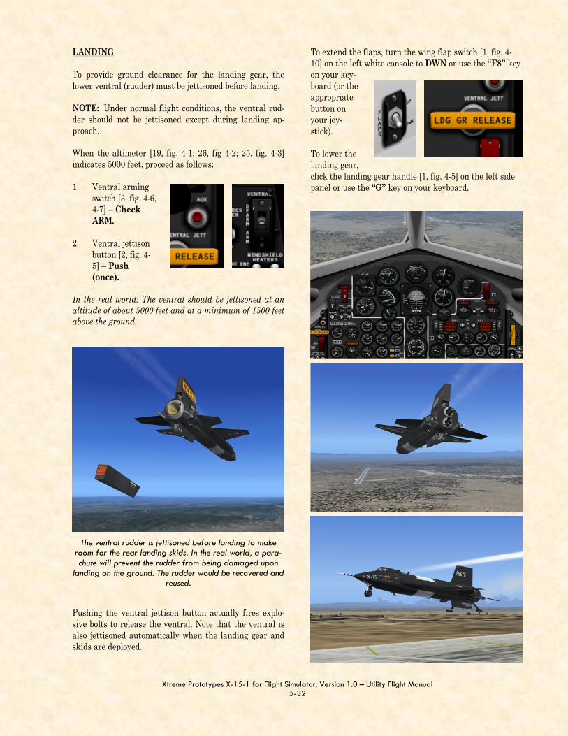
LANDING To provide ground clearance for the landing gear, the lower ventral (rudder) must be jettisoned before landing. NOTE: Under normal flight conditions, the ventral rud-der should not be jettisoned except during landing ap-proach. When the altimeter [19, fig. 4-1; 26, fig 4-2; 25, fig. 4-3] indicates 5000 feet, proceed as follows: 1. Ventral arming
switch [3, fig. 4-6, 4-7] – Check ARM.
2. Ventral jettison button [2, fig. 4-5] – Push (once).
In the real world: The ventral should be jettisoned at an altitude of about 5000 feet and at a minimum of 1500 feet above the ground.
Pushing the ventral jettison button actually fires explo-sive bolts to release the ventral. Note that the ventral is also jettisoned automatically when the landing gear and skids are deployed.
X-15-1 approaching the landing site.
To extend the flaps, turn the wing flap switch [1, fig. 4-10] on the left white console to DWN or use the “F8” key on your key-board (or the appropriate button on your joy-stick). To lower the landing gear, click the landing gear handle [1, fig. 4-5] on the left side panel or use the “G” key on your keyboard.
The ventral rudder is jettisoned before landing to make room for the rear landing skids. In the real world, a para-chute will prevent the rudder from being damaged upon
landing on the ground. The rudder would be recovered and reused.

Xtreme Prototypes X-15-1 for Flight Simulator, Version 1.0 – Utility Flight Manual 5-33
Figure 5-2
Before landing, on the downwind leg of the landing pattern, but in no case above 17,000 feet above sea level, move the vent, pressurize and jettison control lever to PRESSURIZE to prevent sand from entering the airplane propellant system during landing.
To ensure safe recovery, the ventral section of the verti-cal stabilizer (rudder) should be jettisoned at least 1500 feet above the ground.
FLARE COMPLETED 2200 FEET 174 KNOTS
TOUCHDOWN 174 KNOTS (0 SECONDS)
BEGIN 1.3G PULL-OUT 2700 FEET, 240 KNOTS DROP GEAR (10.6 SECONDS)
VENTRAL JETTISON 5000 FEET
(15.6 SECONDS)
ROLL OUT OF TURN 3200 FEET, 240 KNOTS LOWER FLAPS
90-DEGREE POINT 5800 FEET 240 KNOTS, 90 DEGREES FROM RUNWAY (36 SECONDS)
LOW KEY POINT 8700 FEET AT 180 DEGREES (58 SECONDS)
11,900 FEET (82 SECONDS)
16,700 FEET (137 SECONDS)
ALTERNATE LOW KEY POINT 11,500 FEET AT 180 DEGREES (93 SECONDS)
ALTERNATE 90-DEGREE POINT 7100 FEET, 240 KNOTS, 90 DEGREES FROM RUNWAY (54 SECONDS)
VENTRAL JETTISON 5000 FEET
ALTERNATE HIGH KEY POINT 22,500 FEET, 300 KNOTS, GEAR AND FLAPS UP ROLL INTO 30-DEGREE BANKED TURN
HIGH KEY POINT 15,200 FEET, 300 KNOTS, GEAR AND FLAPS UP, ROLL INTO 45-DEGREE BANKED TURN
(183 SECONDS)
106 SECONDS)
LANDING PATTERN

Xtreme Prototypes X-15-1 for Flight Simulator, Version 1.0 – Utility Flight Manual A1-9
XLR-99 ENGINE (LIGHT BLUE-GRAY PANEL, X-15-1d)
6
7
8
9
B
A
1
2
3
4
5
QUICK-START PROCEDURES

Xtreme Prototypes X-15-1 for Flight Simulator, Version 1.0 – Utility Flight Manual A2-1
INSTRUMENT READINGS AFTER SERVICING
The following conditions should be observed after servic-ing the X-15: Service panel: 1. Liquid oxygen tank volume gauge [1, fig. 4-4] – 1017
gallons.
2. Water-alcohol (or ammonia) tank volume gauge [2, fig. 4-4] – 1445 gallons.
3. Turbopump hydrogen peroxide (H2O2) tank volume gauge [3, fig. 4-4] – 78 gallons.
4. Propellant source (helium) tank pressure gauge [4, fig. 4-4] – 3200-3800 psi.
5. Engine and propellant control source tank (nitrogen or helium) pressure gauge [5, fig. 4-4] – 3200-3800 psi.
6. Engine purge and emergency (nitrogen or helium) tanks pressure gauge [7, fig. 4-4] – 3200-3800 psi, both pointers.
7. APU source (helium) tanks pressure gauge [9, fig. 4-4] – 3200-3800 psi, both pointers.
8. APU H2O2 tanks volume gauge [10, fig. 4-4] – 60-75 gallons, both pointers.
Appendix 2: INSTRUMENT READINGS
9. Cabin helium tank pressure gauge [12, fig. 4-4] – 3200-3800 psi.
10. Liquid N2 tank volume gauge [13, fig. 4-4] – 25-30 gallons.
Main panel (XLR-11 engines): 1. Helium source pressure gauge [6, fig. 4-1] – 3200-
3800 psi.
2. Nitrogen source pressure gauge [81, fig. 4-1] – 3200-3800 psi, both pointers.
3. APU source pressure gauge [58, fig. 4-1] – 3200-3800 psi, both pointers.
4. Cabin helium source pressure gauge [52, fig. 4-1] – 1000 to 3400 psi.
5. AC voltmeters [33, 40, fig. 4-1] – 200 volts (external power).
6. Nitrogen line tank and control pressure gauge [78, fig. 4-1] – “T” pointer, 0 psi; “C” pointer, 400 to 475 psi.
Main panel (XLR-99 engine): 1. Propellant source pressure gauge [12, fig. 4-2; 13,
fig. 4-3] – 3200-3800 psi.
2. H2O2 source and purge pressure gauge [4, fig. 4-2, 4-3] – 3200-3800 psi, both pointers.
3. APU source pressure gauge [67, fig. 4-2; 65, fig. 4-3] – 3200-3800 psi, both pointers.
4. Cabin helium source pressure gauge [61, fig. 4-2; 59, fig. 4-3] – 1000 to 3400 psi.
5. AC voltmeters [43, 50, fig. 4-2; 45, fig. 4-3] – 200 volts (external power).
6. H2O2 tank and engine control pressure gauge [86, fig. 4-2; 79, fig. 4-3] – “T” pointer, 0 psi; “C” pointer, 575-600 psi.

Produced with the financial participation of
Administrator of The Canada New Media Fund
funded by the Department of Canadian Heritage
Xtreme Prototypes X-15-1 for Flight Simulator, Version 1.0 – Utility Flight Manual (English). Copyright © 2007 by Xtreme Prototypes, Inc. The software and the present manual are protected by international copyright laws. Please do not make unauthorized copies of the software and/or its related components and documentation, including the present user manual. No part of this document may be reproduced or redistributed in any form or by any means without the written permission of the publisher. All images in this document are actual screenshots of the Xtreme Prototypes X-15-1, X-15-2/3 and X-15A-2 add-on rocket aircraft for Flight Simulator, taken in the Microsoft® Flight Simulator 2004 and Flight Simulator X game environments, except where otherwise noted. Microsoft, Microsoft Flight Simulator, Windows and DirectX are either registered trademarks or trademarks of Microsoft Corporation. Other com-pany or product names mentioned herein may be trademarks or registered trademarks of their respective owners. Software features and manual contents are subject to change without notice. Portions of this manual have been inspired or adapted from the original real-world X-15 utility flight manuals published during the 1950s and 1960s by the U.S. Air Force and North American Aviation. NASA and AFFTC photos have been used in some sections for comparison and illustration purposes only and are the property of their respective owners as credited. Xtreme Prototypes is not affiliated with NASA, North American Aviation (Boeing), the U.S. Air Force, or any other company, entity or government organization related to the X-15 research program. This product is neither sponsored nor endorsed by NASA.
treme Prototypes X www.xtremeprototypes.com
Xtreme Prototypes, Inc. P.O. Box 64, Station Place du Parc
Montreal (QC), CANADA H2X 4A3