Utility Design & Inspection Policy Manual
87
UTILITY DESIGN AND INSPECTION POLICY MANUAL 1 City of Joliet Utility Design & Inspection Policy Manual ADOPTED: By Ordinance #2019-17934 City of Joliet Department of Public Utilities 150 W. Jefferson Street, Joliet, IL 60432 April 15, 2019
Transcript of Utility Design & Inspection Policy Manual

UTILITY DESIGN AND INSPECTION POLICY MANUAL 1
City of Joliet
Utility Design & Inspection
Policy Manual
ADOPTED: By Ordinance #2019-17934
City of Joliet Department of Public Utilities
150 W. Jefferson Street,
Joliet, IL 60432
April 15, 2019

UTILITY DESIGN AND INSPECTION POLICY MANUAL 2
Table of Contents
1 INTRODUCTION ..................................................................................................................................... 6
1.1 DESIGN MANUAL PURPOSE AND GOAL .............................................................................. 6
1.2 DESIGN MANUAL INTERPRETATION................................................................................... 7
1.3 DESIGN MANUAL REVISION .................................................................................................... 7
1.4 AUTHORITY .................................................................................................................................... 7
1.5 STANDARD DETAILS AND SPECIFICATIONS .................................................................... 7
1.6 PERMITS AND FEES ..................................................................................................................... 7
2 GENERAL STANDARDS ....................................................................................................................... 7
2.1 WATER AND SEWER EASEMENTS ........................................................................................ 7
2.2 UTILITY INSTALLATION RESTRICTIONS ........................................................................... 8
2.3 CRITICAL CUSTOMERS ............................................................................................................... 8
2.4 GIS DATA STANDARDS ............................................................................................................... 9
2.5 DRAWING REQUIREMENTS .................................................................................................. 11
3 WATER SYSTEM DESIGN CRITERIA ........................................................................................... 11
3.1 GENERAL WATER SYSTEM DESIGN REQUIREMENTS ............................................... 11
3.1.1 Design Approval ................................................................................................................ 11
3.1.2 IEPA Permit Required ..................................................................................................... 11
3.1.3 Public and Private Water Mains .................................................................................. 11
3.1.4 Basis of Design ................................................................................................................... 12
3.2 WATER MAIN REQUIREMENTS ........................................................................................... 12
3.2.1 Water Distribution and Transmission Material .................................................... 12
3.2.2 Location in the Public Right-Of-Way ......................................................................... 12
3.2.3 Water Main Sizing ............................................................................................................. 12
3.2.4 Water Main Taps (4” and Greater) ............................................................................. 12
3.2.5 Water Main Taps (<4”) ................................................................................................... 12

UTILITY DESIGN AND INSPECTION POLICY MANUAL 3
3.2.6 Joint Restraint .................................................................................................................... 13
3.2.7 Oversizing Requirements .............................................................................................. 13
3.2.8 Limits of Installation ........................................................................................................ 13
3.2.9 System Looping ................................................................................................................. 13
3.3 WATER MAIN SEPARATION ................................................................................................. 13
3.3.1 Horizontal Separation ..................................................................................................... 13
3.3.2 Vertical Separation ........................................................................................................... 14
3.3.3 Depth of Cover ................................................................................................................... 15
3.4 WATER SYSTEM SERVICES ................................................................................................... 15
3.4.1 Water Service Material ................................................................................................... 16
3.4.2 Water Service Line Sizing .............................................................................................. 16
3.4.3 Water Supply Control Valves ....................................................................................... 16
3.4.4 Water Meter Requirements .......................................................................................... 17
3.4.5 RPZ Valve Requirements ............................................................................................... 18
3.4.6 Master Metering ................................................................................................................ 18
3.4.7 Connecting to Existing Water Mains ......................................................................... 18
3.4.8 Water Service Connections ........................................................................................... 18
3.4.9 Abandoning Existing Services ...................................................................................... 19
3.5 FIRE PROTECTION REQUIREMENTS ................................................................................. 19
3.5.1 Fire Protection Supplies ................................................................................................. 19
3.5.2 Public Fire Flow Requirements ................................................................................... 20
3.5.3 Private Fire Protection Requirements ...................................................................... 20
3.5.4 Fire Hydrant Requirements .......................................................................................... 20
3.6 WATER SYSTEM VALVE REQUIREMENTS ...................................................................... 21
3.6.1 Valve Boxes and Valve Vaults ....................................................................................... 21
3.6.2 Valve Locations .................................................................................................................. 21
3.7 WATER SYSTEM CASING REQUIREMENTS ..................................................................... 21
3.7.1 Water Main Casing Pipes ............................................................................................... 21
3.7.2 Casing Pipe Material ........................................................................................................ 22
3.7.3 Sizing of Casing Pipes ...................................................................................................... 22
3.8 WATER SYSTEM INSPECTION REQUIREMENTS .......................................................... 22
3.8.1 Water System Testing Requirements ....................................................................... 23
3.8.2 Water System Inspection Requirements ................................................................. 24
4 SANITARY SYSTEM DESIGN CRITERIA ..................................................................................... 25
4.1 GENERAL SANITARY SYSTEM REQUIREMENTS ........................................................... 25

UTILITY DESIGN AND INSPECTION POLICY MANUAL 4
4.1.1 Design Approval ................................................................................................................ 25
4.1.2 IEPA Permit Required ..................................................................................................... 25
4.1.3 Public and Private Sanitary Sewers ........................................................................... 26
4.1.4 New Business Wastewater Survey ............................................................................. 26
4.1.5 Wastewater Discharge Permit Determination ...................................................... 27
4.2 SANITARY SEWERS REQUIREMENTS ............................................................................... 27
4.2.1 Sanitary Sewer Pipe Materials ..................................................................................... 27
4.2.2 Location in the Public Right-Of-Way ......................................................................... 27
4.2.3 Curvilinear Alignment of Sanitary Sewers .............................................................. 27
4.2.4 Sewer and Water Main Separation ............................................................................ 28
4.2.5 Depth of Pipe Cover ......................................................................................................... 28
4.2.6 Overhead Sewers .............................................................................................................. 28
4.2.7 Sanitary Sewer Sizing ...................................................................................................... 28
4.2.8 Oversizing and Extra Depth Requirements ............................................................ 28
4.2.9 Sanitary Sewer Minimum Slopes ................................................................................ 28
4.2.10 Sanitary Sewer Maximum Slopes ............................................................................... 29
4.2.11 Limits of Installation ........................................................................................................ 29
4.3 SANITARY SEWER MANHOLE REQUIREMENTS ........................................................... 29
4.3.1 Manhole Location and Spacing .................................................................................... 29
4.3.2 Manhole Sizing Requirements ..................................................................................... 30
4.3.3 Invert Elevations in Manholes ..................................................................................... 30
4.3.4 Drop Manholes ................................................................................................................... 31
4.3.5 Requirement for Inspection Manholes and Clean-Outs ..................................... 31
4.3.6 Grease/Oil/Sand Trap Manholes ................................................................................ 31
4.3.7 Polymer Manholes ............................................................................................................ 31
4.4 SANITARY SEWER CONNECTION REQUIREMENTS .................................................... 32
4.4.1 Connecting to existing sewer ....................................................................................... 32
4.4.2 Extension of Existing Services ..................................................................................... 33
4.4.3 Disconnection of Existing Services ............................................................................ 33
4.5 SANITARY SEWER CASING REQUIREMENTS ................................................................. 33
4.5.1 Casing Pipes ........................................................................................................................ 33
4.5.2 Casing Pipe Material ........................................................................................................ 33
4.5.3 Sizing of Casing Pipes ...................................................................................................... 34
4.6 LIFT STATION REQUIREMENTS .......................................................................................... 34
4.6.1 Force Main Requirements ............................................................................................. 34
4.6.2 Facility Requirement ....................................................................................................... 34

UTILITY DESIGN AND INSPECTION POLICY MANUAL 5
4.7 SANITARY SEWER INSPECTION REQUIREMENTS ...................................................... 35
4.7.1 SANITARY INSPECTION PROCEDURES .................................................................... 35
5 DESIGN REFERENCES....................................................................................................................... 37
5.1 DESIGN REFERENCES .............................................................................................................. 37
LIST OF TABLES Table Page No.
1 Fire Flow Requirements .................................................................................................................. 20
2 Water System Casing Pipe Material ............................................................................................ 22
3 Table of Local Limits ......................................................................................................................... 26
4 Sanitary Sewer Minimum Slopes.................................................................................................. 29
5 Minimum Manhole Sizing Requirements .................................................................................. 30
6 Sanitary Sewer Casing Pipe Material .......................................................................................... 34
LIST OF APPENDICES Appendix A Approved Materials List
Appendix B Standard Details
Appendix C Lift Station Design Requirements
Appendix D General Notes
Appendix E Pretreatment Questionnaire
Appendix F Critical Customer Questionnaire


UTILITY DESIGN AND INSPECTION POLICY MANUAL 7
1.2 DESIGN MANUAL INTERPRETATION
This manual is composed of written engineering standards, references to established
standards of other organizations and agencies, and standard details of the Joliet Department
of Public Utilities. The Director of the Joliet Department of Public Utilities, whose
interpretation shall be binding and controlling in its application, shall make the
interpretation of any section or of differences between sections. NOTE: Any deviations from
the standards in this manual shall require a technical appeal to the Joliet Director of Public
Utilities.
1.3 DESIGN MANUAL REVISION
This manual may be revised periodically. Revisions will be posted on the City of Joliet
website. In order to review revisions, go to the following website:
http://cityofjoliet.info/departments/public-utilities/resources
1.4 AUTHORITY
The design standards set forth in this manual are adopted pursuant to the authority granted
in the City of Joliet code.
1.5 STANDARD DETAILS AND SPECIFICATIONS
The City of Joliet has developed standard specifications and details that are included as
Appendices to this design manual. The following are the required specifications and detail
references that shall be utilized in all developments in the City of Joliet:
1. Appendix A– Approved Materials List
2. Appendix B – Standard Details
3. Appendix C – Lift Station Design Requirements
4. Appendix D – General Notes
5. Appendix E – Pretreatment Questionnaire
6. Appendix F – Critical Customer Questionnaire
1.6 PERMITS AND FEES
Developers will pay all required permit, review, and inspection fess consistent with all
applicable codes and policies of the City of Joliet prior to commencing work.
2 GENERAL STANDARDS
2.1 WATER AND SEWER EASEMENTS
All public water system and sanitary system components that are not located within a public
right of way shall be placed in a public utility and drainage easement, minimum 15-feet wide

UTILITY DESIGN AND INSPECTION POLICY MANUAL 8
or as directed by the Department of Public Utilities, to the City of Joliet. The easement shall
be granted to the City either through a recorded plat of subdivision or a recorded plat of
easement. The City shall be granted access to these easements if not directly adjacent to
public right-of-way.
At the discretion of the Director of Public Utilities, the City may require additional easements
for future maintenance or repair of the water or sanitary systems, even those portions which
may be located within the public right-of-way. For example, the City may have a deep
sanitary sewer located within the public right-of-way. However, the City may require a public
utility and drainage easement parallel to the edge of the right-of-way to accommodate future
repair of the sanitary sewer if it ever needs to be excavated and repaired.
2.2 UTILITY INSTALLATION RESTRICTIONS
No building will be allowed to encroach on a water or sewer easement.
Regardless of the easement width, buildings shall have a sufficient setback from the water
or sewer pipe such that buildings, building foundations or building slabs will not be
undermined or damaged by a water or sewer main break or subsequent repair.
Buildings, building slabs or structures proposed outside of the easement but parallel to a
sewer main at a horizontal distance less than equal to the depth (invert) of the sewer main,
shall be required to submit structural and soil calculations signed and sealed by an Illinois
Registered Professional Engineer. This report shall verify integrity of the proposed structure
under the condition of a sewer main failure.
Buildings, building slabs or structures proposed outside of the easement but parallel to a
water main within 12 feet, shall be required to submit structural and soil calculations signed
and sealed by an Illinois Registered Professional Engineer. This report shall verify integrity
of the proposed structure under the condition of a water main failure.
No City Utility will be installed in a location that creates an undue hardship to the utility to
maintain the Utility. Examples include: underneath a berm, in a low area that will have
periodic ponding, in a known ditch that conveys water during storms, and under parking lots
on private property.
2.3 CRITICAL CUSTOMERS
“Critical Customers” are defined as consumers or service connections that are critical to
community resiliency (public safety or health), or demand a large volume of water to sustain
economic resiliency, or service a susceptible population such as and specific to the City of
Joliet or the Region:
First Responder Organizations / Police / Fire / EMTs
Dental Care and Oral Emergency Centers

UTILITY DESIGN AND INSPECTION POLICY MANUAL 9
Hospitals / Medical Centers (including dialysis centers)
Local / Federal Government Facilities necessary for public safety / health
Mass Transit Stations
Nursing Homes / Assisted Living / Homeless Shelters
Potable Water Haulers
Power Provider
Public Shelters / Cooling Centers / Water Parks / Municipal Pools
Radio / TV Broadcast Centers
State / Local Emergency Management Agencies
Universities / High Schools / Elementary / Middle Schools / Preschool and Day Cares
Any facility that is converted into a critical care facility.
Notifying all impacted customers of a water or sewer emergency is one of our highest
priorities, but specifically knowing where critical customers are and how to communicate
with them assists the whole community in being resilient and in protecting susceptible
populations. Emergency notifications are a time sensitive endeavor, and it is important for
us to be able to contact critical customers quickly. Filling out the Appendix F – Critical
Customer Questionnaire helps the City by providing up to date locations and contact
information for a critical customer facility. If the facility intended for construction is defined
as a critical customer facility, the facility shall be required to provide redundant system
infrastructure to protect the occupants of that facility.
2.4 GIS DATA STANDARDS
The City of Joliet uses GIS (Geographical Information System) technologies to store, manage,
and maintain geographic/spatially-related data. Likewise, the majority of the civil
engineering community has evolved to the point where the predominating design
environment is computer aided design and drafting (CAD). It is the goal of the City to use
GIS and CAD technologies to acquire as-built data for all infrastructure installed. It is the
responsibility of the developer to deliver complete and accurate GIS data prior to acceptance
of any development. The standards below will guide integration of digital engineering CAD
drawings into the GIS environment maintaining the integrity and positional accuracy of the
data.
Blank attribute tables in geodatabase format will be provided by the City for water and
sanitary systems. The fields are already formatted and are to be used for providing attribute
information that corresponds to the infrastructure.
All data shall be in coordinate system: NAD_1983_StatePlane_Illinois_East_FIPS_1201
Feet.

UTILITY DESIGN AND INSPECTION POLICY MANUAL 10
The scope of mapped infrastructure is to include all water infrastructure, all sanitary
sewer infrastructure, public storm sewer infrastructure, and all storm sewer on the
outflow side of a detention basin.
The scope of applicable projects includes all developments with public water and sewer
mains and all site projects greater than one (1.0) acre.
Do not rename any of the attribute tables.
Do not alter the original formatting and structure of the attribute tables, or replace them
with similar tables.
Use the correct table being used for each sewer line, structure type, or other feature.
All required fields filled in with appropriate data. Additional information entered in the
non-required fields is also helpful.
Correct units and precision used for pipe diameter, pipe length, upstream elevation, etc.
Correct code from the lookup tables used when required. The lookup tables can be found
in in the metadata associated with the geodatabases. Whenever possible use the code
that most accurately describes the item.
Removed or abandoned features need to be denoted as such within the attribute table.
All sanitary sewer and storm pipes shall be drawn in the direction of flow.
Collect GPS points of structures prior to burying.
General Notes:
The lookup tables are not linked to the attribute tables, so they are used as a reference.
Adhere to the requirements in any “Type” column in the Attribute Table Requirements.
This formatting must be adhered to in order for the attribute information to be used
properly.
Excel (.xls) files can be accepted for the attribute tables as long as the formatting is kept
the same and none of the field names are changed or deleted, however the original
geodatabase file format is preferred.
If it is unclear which attribute tables should be used or how to code any of the required
fields please consult with the City prior to delivering your digital data submission.
Data shall be submitted in full GIS geodatabase format or AutoCAD drawings with Civil
3D Models.
Refer to external City documents regarding more detailed CAD and GIS standards and
guidelines.
All files are to be submitted at both the design stage (at the time of plan approval) and
as-built stage (upon completion of construction.

UTILITY DESIGN AND INSPECTION POLICY MANUAL 11
2.5 DRAWING REQUIREMENTS
All drawings prepared for the City of Joliet Public Utilities Department will include the
general notes found in Appendix D – General Notes of this Design Manual.
All projects shall require the submittal of As-Built drawings. As-built drawings shall be red-
line updated monthly during construction and will be subject to review by City inspectors.
Drawings submitted upon project completion shall show the as-built location of all utilities
and utility structures and be provided in AutoCAD and PDF format.
3 WATER SYSTEM DESIGN CRITERIA
3.1 GENERAL WATER SYSTEM DESIGN REQUIREMENTS
3.1.1 Design Approval
The Joliet Department of Public Utilities shall approve all designs and shall alter design
requirements only as necessary to meet the City water system plan. The Department of
Public Utilities shall review and comment on all designs in conjunction with review
specialists as required to interpret plans. All materials will conform to Appendix A –
Approved Materials List of this Design Manual.
The City of Joliet’s Standard Details, as currently adopted by the Department of Public
Utilities, should be used in all construction plans. The standard details are found in Appendix
B – Standard Details of this Design Manual. Any modifications or substitutions to these
standard details require approval from the Director of Public Utilities.
3.1.2 IEPA Permit Required
All public water main extensions require an IEPA Construction permit, prior to construction.
It is the responsibility of the interested party to prepare the necessary documents to secure
all permits. The City of Joliet will review all permit applications and sign only when all
information is correctly provided. All required permits must be obtained and provided to the
Joliet Director of Public Utilities prior to commencing any utility work.
3.1.3 Public and Private Water Mains
During construction and prior to City acceptance, it is the sole responsibility of the developer
to maintain any new infrastructure that is proposed under the permit. When the water
distribution system is complete and the improvements have been formally accepted by the
City, the Joliet Department of Public Utilities shall be responsible for the repairs and
maintenance of all Public water mains. Maintenance and repairs for private components
shall be the responsibility of the property owner, or property owner’s association. In such
cases where the City performs maintenance or repairs on the private water distribution
system, the City reserves the right to charge the property owner for necessary work.

UTILITY DESIGN AND INSPECTION POLICY MANUAL 12
NOTE: All engineering plans shall clearly differentiate between all portions of the
public and private water distribution system.
3.1.4 Basis of Design
All water systems shall be designed using the Hazen-Williams method. The coefficient of
roughness shall equal one hundred (c = 100).
3.2 WATER MAIN REQUIREMENTS
3.2.1 Water Distribution and Transmission Material
Ductile iron pipe shall be cement-lined, have a minimum Class 52 thickness designation, and
polyethylene encasement. Water main shall be zinc coated. For information regarding
applicable ANSI, AWWA, and ASTM designations, refer to Appendix A – Approved Materials
List of this Design Manual.
3.2.2 Location in the Public Right-Of-Way
Water mains shall be generally located on the north and west sides of the public right-of-
way, or as directed by the Director of Public Utilities. All designs will provide for the most
efficient system design while considering ease of future maintenance. All efforts will be made
to minimize the amount of pipe that is under PCC pavement and parking stalls.
3.2.3 Water Main Sizing
Water mains shall be constructed of 8-inch diameter or 12-inch diameter pipe, or as directed
by the Department of Public Utilities. No water mains less than 8-inch diameter will be
allowed without approval from the Director of Public Utilities.
3.2.4 Water Main Taps (4” and Greater)
Use two-piece bolted sleeve ductile iron type with mechanical joints. Only under special
circumstances will the stainless steel type be allowed to be substituted for the cast iron
sleeve. Provide joint accessories. See Appendix A – Approved Materials List for approved
manufacturers.
The City of Joliet Water Department shall be responsible for completing all taps to existing
water mains. Contractor will be responsible for calling 815-724-4220 to schedule an
appointment with the Water Department. Appointments are available on Tuesdays and
Thursdays.
3.2.5 Water Main Taps (<4”)
For 1” taps, a direct tap may be made using a 1” corporation stop.
For 1.5” and 2” taps, a tapping saddle with U bolts will be required.

UTILITY DESIGN AND INSPECTION POLICY MANUAL 13
The City of Joliet Water Department shall be responsible for completing all taps to existing
water mains. Contractor will be responsible for calling 815-724-4220 to schedule an
appointment with the City Department of Public Utilities. Appointments are available on
Tuesdays and Thursdays.
3.2.6 Joint Restraint
All mechanical joint fittings shall have restraining glands installed. Lengths of pipe restraint
shall be determined from manufacturers’ installation specifications.
3.2.7 Oversizing Requirements
It may be determined that the water main be oversized in order to provide service to
additional benefiting properties. Consideration of oversizing pipes will be made on a case by
case basis at the sole discretion of the Director of the Public Utilities Department.
3.2.8 Limits of Installation
At a minimum, water main shall extend across the frontage of the property, at the developer’s
cost, such that a connection could be made with minimal disturbance in the future. In some
cases, the City may require that the water main be installed from one corner to the diagonally
opposite corner, at the developer’s cost.
All water main stubs for future extension shall terminate with a valve and hydrant.
Restrained joints shall be located 40 feet from the capped end.
3.2.9 System Looping
Each 8- inch diameter water main shall be looped at a distance not to exceed 1,000 feet.
Each 12- inch diameter and larger water main shall be looped at a distance not to exceed
3,000 feet.
No dead-end water mains shall be allowed and hydrant leads must comply with current IDPH
guidance.
3.3 WATER MAIN SEPARATION
Water mains and water service lines shall be protected from sanitary sewers, storm sewers,
combined sewers, house sewer service connections, drains, and sanitary sewer force main.
3.3.1 Horizontal Separation
Water mains shall be laid at least 10 feet horizontally from any existing or proposed drain,
storm sewer, sanitary sewer, combined sewer or sewer service connection.
Water mains may be laid closer than 10 feet to a sewer line when:
Local conditions prevent a lateral separation of ten feet;

UTILITY DESIGN AND INSPECTION POLICY MANUAL 14
The water main invert is at least 18 inches above the crown of the sewer; and
The water main is either in a separate trench or in the same trench on an undisturbed
earth shelf located to one side of the sewer.
When it is impossible to meet the conditions above, the drain or sewer shall be constructed
of slip-on mechanical joint cast or ductile iron pipe, or PVC SDR 26 pipe meeting the
requirements for water main. The drain or sewer shall be pressure tested to the maximum
expected surcharge head before backfilling with no leakage allowed in the area of required
water main protection. A City of Joliet representative shall witness this testing.
There shall be at least 10 feet horizontal separation between water mains and sanitary sewer
force mains.
Water mains must be separated at least 25 feet from septic tanks, disposal fields, seepage
beds, and sewage lift stations.
3.3.2 Vertical Separation
A water main shall be laid so that its invert is 18 inches above the crown of the drain or sewer
whenever water mains cross storm sewers or sewer service connections. The vertical
separation shall be maintained for that portion of the water main located within 10 feet
horizontally or any sewer or drain crossed. A length of water main pipe shall be centered
over the sewer to be crossed with joints equidistant from the sewer or drain.
The sewer shall be constructed of slip-on or mechanical joint cast or ductile iron pipe, or PVC
SDR 26 pipe, meeting the requirements for water main when:
It is impossible to obtain the proper vertical separation as described above; or
The water main passes under a sewer or drain.
A vertical separation of 18 inches between the invert of the sewer or drain and the crown of
the water main shall be maintained where a water main crosses under a sewer. Support the
sewer or drain lines to prevent settling and breaking of the water main.
If the invert of the water main is not 18 inches above the crown of the sewer when the pipes
cross, a casing pipe can be installed around either the water main or sewer in lieu of
constructing the sewer with water main equivalent pipe. The casing pipe must be a material
that is approved for use as water main. The casing must extend on each side of the crossing
at least 10 feet as measured at right angles from the outside edge of water main pipe to the
outside edge of the sewer pipe. Pipe support shall be provided within the casing pipe and
ends of the casing shall be filled with an approved non-shrink grout.
At crossings when the invert of the water main is not 18 inches above the crown of the storm
sewer, and the sewer crossed the water main at right angles, the storm sewer can be
constructed with reinforced concrete pipe using flexible gasket joints meeting ASTM C-361

UTILITY DESIGN AND INSPECTION POLICY MANUAL 15
or ASTM C-443 instead of providing a casing pipe or constructing the storm sewer with water
main equivalent pipe. If gasketed storm sewer piping is proposed, it shall be installed
between adjacent storm structures. The drain or sewer shall be pressure tested to the
maximum expected surcharge head before backfilling with no leakage allowed in the area
within 10 feet of the water main. A City of Joliet representative shall witness this testing.
Construction shall extend on each side of the crossing until the distance from the water main
to the sewer or drain line is at least 10 feet as measured at right angles from the outside edge
of the water main pipe to the outside edge of the sewer pipe.
Where a water main passes over an existing or proposed force main, an 18- inch vertical
separation shall be provided at the crossing. (Note: A force main shall not be allowed to be
above the water main at the crossing.)
3.3.3 Depth of Cover
All pipe shall be laid to a minimum depth of 5.0 feet measured from the proposed ground
surface to the top of the pipe, unless specifically allowed otherwise in special circumstances
by the Director of Public Utilities. If approved, the pipe shall be insulated with 2-inch exterior
grade rigid insulation board. One 2-inch thick sheet of insulation shall be provided for each
6 inches of cover below the required 5- foot minimum depth and extend a minimum of 12
inches on each side of the water main. The insulation shall have a minimum R- value of R-9,
and comply with ASTM C 578- 92 Type 1X.
3.4 WATER SYSTEM SERVICES
Water system services shall not cross a divided highway. In instances where water services
are to be provided on both sides of a divided highway, parallel water mains shall be installed
in the right of way.
No more than one building shall be supplied from one service pipe. Whenever possible, the
service pipe shall enter the building in a direct line with the curb stop and tap. The service
pipe shall not be allowed to cross onto an adjacent property. Said pipe shall be provided with
a valve before and after the water meter, not less than 1- foot inside of the wall or above the
foundation floor (main building shutoff valve). The property owner shall be responsible for
the maintenance, repair or replacement of the main shutoff valves.
Every building, except auxiliary buildings shall be individually metered.
All valves shall be arranged so that each line can be shut off from the exterior of the building.
Shut-off valve locations shall be shown on drawings.

UTILITY DESIGN AND INSPECTION POLICY MANUAL 16
3.4.1 Water Service Material
Service lines 2 inches or less (≤ 2”), inside diameter, shall be copper pipe, “Type K”. All
services 4 inches or greater (≥ 4”), inside diameter, shall be Class 52 ductile iron pipe with
cement lining. See Appendix A – Approved Materials List of this Design Manual.
3.4.2 Water Service Line Sizing
The water service line sizing will follow the Illinois Plumbing Code. A minimum 1” service
line is required to each unit. 3” service lines are not allowed.
3.4.3 Water Supply Control Valves
For residential, single family, control valves shall follow the following requirements:
1. Provide B-box shutoff valves for residential buildings.
2. Extend B-box to finished grade.
3. B-boxes cannot be located in driveways or sidewalks.
4. Curb shall be stamped “W” in alignment with B-box.
For residential, multi-unit, buildings control valves shall follow the following requirements:
1. Separate complete water services shall be required from the water main for each.
Each service line shall be separately metered.
2. Locate B-boxes together in the same order as the units.
3. Extend B-boxes to finished grade.
4. An address tag must be attached to each B-Box. Tags shall be 316 stainless steel,
engraved with unit number/address.
5. In lieu of separate services and upon the approval of the Director of Public Utilities,
meters may be allowed in a central place accessible 24-hour from the building
exterior to Department of Public Utilities personnel for maintenance, inspection, or
shutoff. Each meter must be supplied a locking valve approved by the City. The meter
room will be allowed provided the door lock is keyed to conform with the City of Joliet
master keying requirements. Alternatively, a knox box may be installed.
For single-unit Commercial buildings control valves shall follow the following requirements:
1. Provide B-box shutoff valves.
2. Extend B-box to finished grade.
3. B-boxes cannot be located in driveways or sidewalks.
4. Curb shall be stamped “W” in alignment with B-box.
For Multi-unit Commercial buildings and units that share a single water service for fire
protection and domestic supply control valves shall follow the following requirements:
1. Provide one main outside shutoff valve installed on the service line.

UTILITY DESIGN AND INSPECTION POLICY MANUAL 17
2. Buildings on slab must have a shutoff valve installed on the service line located in the
outside wall of the building that faces the street and labeled “WATER” with 6” letters.
3. Unit meters shall be in a central place accessible from the building exterior to
Department of Public Utility personnel for maintenance, inspection or shutoff. Each
meter must be supplied a locking valve approved by the City. The door lock for the
meter room must be keyed to conform with the City of Joliet master keying
requirements. Alternatively, a knox box may be installed.
4. An address tag must be attached to each shut-off valve. Tags shall be 316 stainless
steel, engraved with unit number/address.
3.4.4 Water Meter Requirements
Water Meters shall adhere to the following requirements:
1. Locate all meters in an accessible location for City personnel to inspect and replace.
A crawl space, pit or under a stairway will not be considered accessible.
2. Provide protection from damage for water meter in non-residential buildings.
3. Provide full port ball valve within 16” of entering the building space and immediately
after the meter.
4. Water meters shall be mounted between 18 inches and 48 inches above the floor.
Meters are not permitted above a ceiling or enclosed in a wall.
5. Water meters shall generally be located in the same room where the water service
pipe enters the building.
6. The preferred location for a water meter is a mechanical room or basement room,
adjacent to the outside wall of the building.
7. A water meter in a finished space may be enclosed in a closet, provided that a door is
installed to allow ready access for maintenance and inspection. Adequate meter
clearances must be incorporated.
8. Water meters shall not be installed in a location that will be blocked by other
equipment, including hot water heaters, water softeners, and other HVAC / plumbing
equipment.
9. A generally clear floor area shall be maintained in front of each meter, a minimum of
36 inches out from the center / flow line of the meter. A minimum of 12 inches
clearance shall be provided for all other sides of the meter.
10. In special situations where meters are installed in finished building spaces, conduit
shall be provided and installed for future routing of the AMR wire to the exterior of
the building.
11. For multi-unit buildings AMRs shall be mounted on the outside of the meter
room/sprinkler room.

UTILITY DESIGN AND INSPECTION POLICY MANUAL 18
3.4.5 RPZ Valve Requirements
The following are the City requirements for RPZ valves:
1. RPZ required on domestic water supply to all non-residential buildings.
2. RPZ required on water supply to all fire sprinkler systems.
3. RPZ required on all irrigation systems.
4. Upon a showing of circumstances to warrant same, a double check valve may be
substituted for an RPZ device on fire protection systems with the approval of the
Director of Public Utilities.
5. Install RPZ a minimum of 12" and a maximum of 5 feet above the finished floor
elevation measured from the bottom of the device.
6. Install RPZ a minimum distance of 12" from any building structure of safety devices
as measured from the body of the device.
7. Install RPZ a maximum of 5 feet from a floor drain.
3.4.6 Master Metering
Every separate building supplied with City water must have its own separate service
connection and meter. A single service line and a Master Meter can be used for two or more
buildings located on the same lot or for apartment developments, trailer courts or similar
projects covering one lot. In these Master Meter applications where an assured continuous
supply must be maintained, the domestic development demand can be split and two meters
may be used, each with its own service connection to the City main and then manifolded on
the customer side of the meter. Beyond meeting the need to provide an uninterrupted supply
to a development, the manifolding of more than 2 meters shall not be allowed.
3.4.7 Connecting to Existing Water Mains
Connection to the end of an existing water main shall be with a valve only. No new water
main should be connected to the existing water main unless the new water main can be
pressure tested separately. Connection to an existing water main shall be done by pressure
connection only when authorized by the Director of Public Utilities. Pressure connection and
valve shall be located within the valve vault. No pressure connection shall be within 3’ of an
existing water main joint. If pressure connection cannot be done, use a cut in sleeve and tee
connection. All fittings will be swabbed out with a chlorine solution of at least 50 mg/L. A
City Representative must test this solution.
3.4.8 Water Service Connections
Service connections to water mains are not permitted until after bacteriological sampling
and analysis has been completed to the satisfaction of the Director of Public Utilities. No
water service connection to new water mains shall be made by any person or firm other than
a State of Illinois licensed contractor, with a State of Illinois licensed plumber on the job, and

UTILITY DESIGN AND INSPECTION POLICY MANUAL 19
bonded with the City. The City of Joliet Water Department shall be responsible for
completing all taps to existing water mains. Contractor will be responsible for calling 815-
724-4220 to schedule an appointment with the City Department of Public Utilities.
Appointments are available on Tuesdays and Thursdays.
3.4.9 Abandoning Existing Services
All existing services shall be abandoned at the corporation stop (close corporation stop, cut
services, and install copper disk). Existing services shall not be reused without approval of
the City. Disconnection of all services must be performed prior to the demolition of an
existing structure.
3.5 FIRE PROTECTION REQUIREMENTS
3.5.1 Fire Protection Supplies
Fire flow requirements will be approved by the Director of Public Utilities.
The required fire flows may be computed at a residual pressure of 25 psi for Fire Department
use. It should be recognized that higher residual pressures may be necessary for specific fire
protection demands.
The following flow requirements are guidelines which will be modified based upon
construction types, size and height of the buildings:

UTILITY DESIGN AND INSPECTION POLICY MANUAL 20
TABLE 1
Fire Flow Requirements
Use Flow (gpm)
Manufacturing and Storage 3,000 to 5,000
Institutional (Assumed limited hazard, fire resistive construction, or
automatic protective devices provided)
3,000 to 4,000
Commercial and Mercantile 3,000 to 5,000
Business and Office (Assumed limited hazard) 2,500 to 3,500
Single Family Detached Residential (1,000 gpm typically used
for average home size and spacing)
1,000 to 1,500
Town or Row Houses (1,500 gpm average, additional quantity due to
risk of fire to adjoining structures or units)
1,000 to 2,000
Apartments (Low-end requirements for fire resistive structures,
higher-end requirements for wood frame, similar construction)
3,000 to 4,000
3.5.2 Public Fire Flow Requirements
Public fire flow requirements (Fire Department pumper supply) and domestic consumption
demands are cumulative.
3.5.3 Private Fire Protection Requirements
Private fire protection demands (standpipe systems, sprinkler systems, etc.) will not be
considered cumulative with public fire flow demands. These requirements are based upon
the building height, area, use, and construction type.
3.5.4 Fire Hydrant Requirements
Fire hydrants shall be located 7.5 feet from the right-of-way within north or west parkways.
All points of buildings shall be within 300 feet of all points of the building, as the hose lays
(must be shown on engineering plans).
The linear spacing of hydrants shall not exceed 300 feet.
Fire hydrants outside of public rights-of-way shall be within 10 feet from a paved roadway
and 50 feet from a Fire Department connection (Siamese).

UTILITY DESIGN AND INSPECTION POLICY MANUAL 21
Access to hydrants shall be provided by paved roadways (minimum structural number = 2.5)
routes adequate in width, clearance and strength to support all fire equipment. Such routes
shall be maintained during all seasons of the year.
3.6 WATER SYSTEM VALVE REQUIREMENTS
3.6.1 Valve Boxes and Valve Vaults
Valve boxes may only be used for fire lines that are less than 8 inches in size. The valve box
shall be located in a grassy area; otherwise a valve vault must be used.
Valves for water mains or fire lines 8 inches or larger shall be provided with a vault.
All tapping valves 4” and greater must be installed in vaults.
Vaults for valves on the public water main system shall be provided with lids per the
approved material list stating “City of Joliet” and “Water”. Vaults for valves on the private
portion of the water system shall be provided with lids stating “Water”.
3.6.2 Valve Locations
Valves shall be located such that no more than a maximum of 500 feet to 700 feet of main
may be shut off at any given time. This spacing should be reduced, such that no more than
25 to 30 single-family homes, or 50 multi- family residences (excluding apartment buildings)
would be shut off at any given time.
Where a “tee” is installed, at least two (2) valves will be utilized.
Where a “cross” is installed, at least three (3) valves will be utilized.
Critical customers must have redundant valves in order to provide continuous service to the
facility if there are system breaks. An appropriate configuration of valves to a critical
customer will be reviewed on a case by case basis and approved by the Director of Public
Utilities.
3.7 WATER SYSTEM CASING REQUIREMENTS
3.7.1 Water Main Casing Pipes
Manufactured non- metallic or non-corrosive casing spacers, adjustable runners, or cradles
shall be used to support the pipe in the casing. A minimum of three supports shall be used
per pipe, or per manufacturer’s recommendation. Water main installed within casing pipes
shall have restrained joint construction the entire length of the casing pipe for future
removal if necessary.

UTILITY DESIGN AND INSPECTION POLICY MANUAL 22
3.7.2 Casing Pipe Material
The steel casing pipe shall be bituminous coated, minimum of 30 mils thickness inside and
out, and shall be of leak proof construction, capable of withstanding the anticipated loadings.
The steel casing pipe shall have a minimum yield strength of 35,000 psi and shall meet the
requirements of ASTM A139, Grade B. Ring deflection shall not exceed 2% of the nominal
diameter. The steel casing pipe shall be delivered to the jobsite with beveled ends to
facilitate field welding.
TABLE 2
Water System Casing Pipe Material
3.7.3 Sizing of Casing Pipes
The diameter of the casing pipe shall be a minimum of 12 inches greater than the outside
nominal diameter of the water main.
3.8 WATER SYSTEM INSPECTION REQUIREMENTS
The mandatory inspection of water main improvements throughout the City of Joliet will be
performed to ensure that the project is being constructed in accordance with the approved
Final Engineering plans, and to determine if minimum construction and material standards
are achieved. If the developer or contractor desires to deviate from the approved plan or
does not feel that minimum construction standards are being satisfied, he/she is responsible
for contacting the City immediately. The City of Joliet will not accept a substandard product,
and will not be responsible for any additional cost incurred by the developer / contractor as
a result.
NOTE: Only City of Joliet personnel may operate public water main facilities. The contractor is not permitted to open, close, or adjust any public water valve for any reason. If an emergency situation arises, the contractor shall contact the City of Joliet Public Utilities Department immediately.
Steel Casing Diameter Minimum Wall Thickness (Inches)
20” and 22” 0.344
24” 0.375
28” 0.438
30” 0.469
32” 0.501
34” and 36” 0.532

UTILITY DESIGN AND INSPECTION POLICY MANUAL 23
3.8.1 Water System Testing Requirements
A representative of the City of Joliet Public Utilities Department shall witness all tests. All
tests shall be scheduled 48-hours in advance. The following is a list of tests, which shall be
required for water distribution system improvements in the City of Joliet.
1. After a water main has been installed and before the water main has been placed into
operation, the contractor shall “bag” or cover fire hydrants. The bag shall not be
removed until after the main has become operational. All hydrants shall be placed to
face the road.
2. Flushing: Flushing of all water system improvements will be performed to create a
minimum pipeline velocity of 2.5’/per second.
3. Leakage Test: All public water main improvements shall pass a leakage test in
conformance with AWWA C-600 and C-603. Allowable leakage in gallons per hour
may not exceed that determined by the following formula:
L = Allowable leakage in gallons per hour
L = ND √P N = Number of joints in length of tested main
7400 D = Nominal inside diameter of pipe in inches
P = Average test pressure in psi
4. Pressure Test: All public water main improvements shall pass a pressure test in
conformance with the requirements of ANSI/AWWA C600-87 Section 4, and the
Testing requirements shall follow the “Standard Specifications for Water and Sewer
Main Construction in Illinois”, latest edition.
The contractor shall, after installation of the water main system or parts thereof,
pressure test the new system. A 1-hour pre-test must be made and passed by the
Contractor before scheduling the pressure test with the City. The main shall then be
pressure tested at 150 PSI for a duration of 2-hours in the presence of a
representative of the City of Joliet Public Utilities Department. If a scheduled pressure
test does not pass because of the failure of the Contractor to hold a pre-test, the City
may charge a re-inspection fee to the Contractor. Any other water main work will be
halted until the re inspection fees have been paid.
5. Disinfection: After a successful pressure test, the main shall be chlorinated by gas
injection method only, by a qualified technician. All water mains shall pass a
disinfection test in conformance with AWWA C65186. The following test criteria shall
be met:
a. 50-ppm initial chlorine concentration (chlorine gas only)

UTILITY DESIGN AND INSPECTION POLICY MANUAL 24
b. 25-ppm residual chlorine concentration (after 24-hour duration).
c. Sampling will be performed on two consecutive days, 24-hours apart, Monday
through Thursday, 24-hours after chlorination, and after the main has been
flushed.
A City representative shall determine the number of samples taken. Sample must
be collected by a City of Joliet representative and analyzed by the City’s laboratory.
If after four (4) samplings, the results do not yield two (2) consecutive satisfactory
readings, a re-chlorination will be necessary. Only the City of Joliet Public Utilities
Department shall make the water system operational after receiving satisfactory
lab reports.
6. All private fire service lines shall pass a pressure test in conformance with the
requirements of ANSI/AWWA C600-87 Section 4. The following test criteria shall be
met:
a. 150 psi minimum initial test pressure.
b. 150 psi minimum residual pressure after 2-hours.
c. If an existing valve is utilized for the pressure test, the contractor is responsible
for the performance of the valve.
d. Test to be observed by the City of Joliet representative.
e. If the pressure gauge fails to ‘zero’ at the end of the test, the test will be failed.
3.8.2 Water System Inspection Requirements
The following are the required inspections for any new water system enhancement:
1. Notice: The developer or contractor shall contact the City of Joliet Public Utilities
Department a minimum of 48-hours in advance of a scheduled inspection.
2. Acceptance Inspection: Prior to City acceptance of a public water main, the City of
Joliet Public Utilities Department must inspect and approve the improvement. A
punch list of items, which require corrective action, will be generated, and the
developer will coordinate resolution efforts and schedule a re-inspection. Following
approval, the acceptance process may proceed. Acceptance proceedings will be
coordinated through the Joliet Public Utilities Department.
3. Maintenance Inspection: Prior to the release of a maintenance guarantee, the City of
Joliet Public Utilities Department must inspect and approve the condition of the water
main. This inspection is performed a minimum of one year from the date of City

UTILITY DESIGN AND INSPECTION POLICY MANUAL 25
acceptance of the improvements. This will be at the developer’s request, or following
notification from the financial lending institution that the expiration date for the
maintenance letter of credit is approaching. A punch list of items, which require
corrective action, will be generated, and the developer will coordinate resolution
efforts and schedule a re-inspection. Following approval, the maintenance guarantee
will be released. The release of the maintenance guarantee shall be coordinated with
the Public Works and Utilities Department.
4. B-Boxes: Upon completion of the project, the B-boxes will be adjusted to grade, and
checked to see if they are operational without altering the shutoff key. Locations of
the B-box with GPS point and measurements to the property lines shall be supplied
to the Public Utilities Department and shown on the as-built plans for the project. The
Public Utilities Department will issue a charge for locating B-Boxes. B-box locations
shall be stamped on the curb/sidewalk with a "W".
4 SANITARY SYSTEM DESIGN CRITERIA
4.1 GENERAL SANITARY SYSTEM REQUIREMENTS
All sanitary sewage of domestic and other water borne wastes shall be collected and
conveyed in a sanitary sewer pipe system to a point of discharge into an existing sanitary
sewer system, City of Joliet interceptor, or sewage treatment plant. No sanitary sewage shall
be allowed to enter any storm sewer system or discharge onto the ground or into receiving
streams without first being treated in accordance with city, county, state and federal
regulations.
4.1.1 Design Approval
The Department of Public Utilities shall approve all designs in accordance with the City
Utilities Design Plan. The Department of Public Utilities shall review and comment on all
designs. Designs shall conform to Appendix A – Approved Materials List and Appendix B –
Standard Details. Any modifications to these standard details require approval from the
Director of Public Utilities.
Proposal of new sanitary sewer lift stations requires approval from the Director of Public
Utilities, prior to the design and review process. Appendix C – Lift Station Design
Requirements provides the requirements for lift stations.
4.1.2 IEPA Permit Required
All public sanitary sewer mains require an IEPA Construction permit number prior to
construction. Some private extensions may require a permit, dependent upon the design
population equivalent.

UTILITY DESIGN AND INSPECTION POLICY MANUAL 26
4.1.3 Public and Private Sanitary Sewers
The City maintains public sewer mains and the wye or tie-in location of the private service.
The maintenance and repair costs for the sanitary sewer system beyond the wye or tie-in
location are the responsibility of the property owner or property owner’s association. In
such cases where the City performs maintenance or repairs on the private sanitary sewer
system, the City reserves the right to charge the property owner for necessary work.
NOTE: All engineering plans shall clearly differentiate between all portions of the
public and private sanitary sewers.
4.1.4 New Business Wastewater Survey
All new businesses must complete the Appendix E – Pretreatment Questionnaire. A new
business is defined as any new construction of a facility, any business that is modifying an
existing space, and any business that is entering a previously unoccupied space. All
businesses that will be producing sources of non-domestic wastewater and wish to discharge
wastewater to the City of Joliet wastewater treatment plants must comply with:
The City’s Sewer Use and Pretreatment Ordinance, Prohibited Discharge Limitations
(Ordinance Section Sec. 31-281),and
Local Limits (Specific Limits on Discharge) (Ordinance Section 31-284). The current
local limits are defined in the following table:
TABLE 3
Table of Local Limits
Pollutant Concentration (mg/L)
Arsenic (total) 0.8
Barium (total) 2.0
Cadmium (total) 0.1
Chromium (total) 2.5
Copper (total) 1.0
Cyanide (total) 0.6
Fluoride (total) 1.4
Iron (total) 10

UTILITY DESIGN AND INSPECTION POLICY MANUAL 27
Lead (total) 1.5
Manganese (total) 1.0
Mercury 0.0005
Nickel (total) 1.5
Phenols 1.0
Selenium (total) 1.0
Silver 0.1
Zinc (total) 0.9
pH 6.0-10.0
FOG 100
All dischargers are subject to a wastewater surcharge for BOD and TSS (Ordinance Section
31-412).
4.1.5 Wastewater Discharge Permit Determination
Upon review of the Pretreatment Questionnaire, the City will determine if further
information is needed, and if an Industrial User Discharge Permit subject to the City’s
Industrial Pretreatment program under 40 CFR 403 is required. The City will require a
meeting with the business of interest to discuss the discharge and begin the discharge
application process if needed.
4.2 SANITARY SEWERS REQUIREMENTS
4.2.1 Sanitary Sewer Pipe Materials
All sanitary sewer pipe materials and appurtenances shall be in conformance with Appendix A – Approved Materials List and Appendix B – Standard Details.
4.2.2 Location in the Public Right-Of-Way
Sanitary sewers shall be located within the public right-of-way as directed by the Director of
Public Utilities. In general, sanitary sewers shall be located 7.5 feet inside the right-of-way
on the south and east sides of the right-of-way
4.2.3 Curvilinear Alignment of Sanitary Sewers
Curvature of sanitary sewers is allowed for sewers 8 inches to 12 inches in diameter.
Alignments must follow the general alignment of streets. Only a simple curve design is
acceptable. The radius of curvature will be assessed on a case by case basis and approved as
directed by the Director of Public Utilities. Compression type pipe joints are required and

UTILITY DESIGN AND INSPECTION POLICY MANUAL 28
manholes are required at the beginning and end of all curves. Maximum joint deflection shall
not exceed the manufacturer’s recommendations.
4.2.4 Sewer and Water Main Separation
Sanitary sewers and services that are laid in the vicinity of pipelines designated to carry
potable water shall meet the conditions set forth in Section 3 of this manual.
4.2.5 Depth of Pipe Cover
All pipe shall be laid to a minimum depth of 7 feet measured from the proposed ground
surface to the top of the pipe, unless specifically allowed otherwise in special circumstances
by the Director of Public Utilities. If allowed, sanitary sewer and services with ground cover
less than 4 feet or more than 25 feet must be constructed of ductile iron class 50 pipe with
polyethylene encasement. All sanitary sewers and services with less than 4 feet of cover shall
be insulated with a 2- inch exterior grade rigid insulation board. The insulation shall have a
minimum R-value of R-9, and comply with ASTM C 578-92 Type 1X.
4.2.6 Overhead Sewers
The City reserves the right to require overhead sewers dependent upon the depth of the
sewer main and the loading.
4.2.7 Sanitary Sewer Sizing
Sewer size shall be designed on the basis of a design average flow of not less than 100 gallons
per capita per day and provide a minimum of 2.0 feet per second velocity when flowing full.
Sanitary sewers shall be designed to accept all existing and future demand, based on the fully
developed state under present zoning and the City of Joliet Comprehensive Plan. The
Director of Public Utilities may increase sewer size as required. In no case shall a public
sewer be sized less than 8 inches in diameter.
4.2.8 Oversizing and Extra Depth Requirements
The Director of Public Utilities may request that sanitary sewers either be oversized or
installed at an additional depth in order to provide service to additional benefiting
properties.
4.2.9 Sanitary Sewer Minimum Slopes
Sanitary sewers shall be designed such that the minimum slopes are not less than the
following:

UTILITY DESIGN AND INSPECTION POLICY MANUAL 29
TABLE 4
Sanitary Sewer Minimum Slopes
Pipe Diameter Minimum Slope Desired Slope
6 inch (service pipe only) 1.00% 1.00%
8 inch 0.40% 0.45%
10 inch 0.28% 0.30%
12 inch 0.23% 0.25%
4.2.10 Sanitary Sewer Maximum Slopes
Sanitary sewers shall be designed such that the slopes do not exceed a maximum of 12%. If
the sanitary sewer system cannot be designed without exceeding a slope of 12%, then drop
manhole assemblies shall be utilized.
4.2.11 Limits of Installation
At a minimum, sewers shall extend across the frontage of the property to the limit of the
development, at the developer’s cost, such that a connection can be made with minimal
disturbance in the future. In some cases, the City may require that the sanitary sewer be
installed from one corner to the diagonally opposite corner, at the developer’s cost
4.3 SANITARY SEWER MANHOLE REQUIREMENTS
Manholes for sanitary sewers shall have a minimum inside diameter based upon the sizing
requirements per Section 4.3.2 and shall be constructed of pre-cast concrete units in
accordance with ASTM C 478 and Section 32 of the "Standard Specifications for Water and
Sewer Main Construction in Illinois," or polymer concrete units as required by the Director
of Public Utilities and shall follow the City of Joliet sanitary sewer standards indicated in
Appendix A – Approved Materials List and Appendix B – Standard Details.
Manholes on the public sewer system shall be provided with lids per the approved material
list stating “CITY OF JOLIET” and “SANITARY”. Manholes on the private portion of the sewer
system shall be provided with lids stating “Sewer”.
4.3.1 Manhole Location and Spacing
Manholes shall be located at the junction of two sanitary sewer pipes or at any change in
grade, alignment or size of pipe. The maximum spacing of manholes shall be 400 feet, or as
approved by the Director of Public Utilities.

UTILITY DESIGN AND INSPECTION POLICY MANUAL 30
In general, the City of Joliet prefers to minimize the number of manholes needed for a project.
This will help reduce future operation and maintenance costs.
4.3.2 Manhole Sizing Requirements
The following table provides minimum manhole sizing requirements. For sewer depths
greater than 15’, a minimum 5’ diameter manhole is required.
TABLE 5
Minimum Manhole Sizing Requirements
Minimum Angles Between Pipes for Specific MH Diameters and Pipe Diameters
Pipe Diameter
Manhole Diameter
48-inch
60-inch
72-inch
84-inch
96-inch
108-inch
120-inch
8-inch 38 30 25 22 19 17 15 10-inch 43 34 28 24 22 19 17 12-inch 48 38 32 27 24 21 19 15-inch 56 45 37 31 28 27 22 18-inch 65 51 42 36 32 28 26 21-inch 91 70 57 49 42 37 33 24-inch 104 78 64 54 47 42 37 27-inch 118 87 70 59 52 46 41 30-inch 137 97 77 65 56 50 45 36-inch N/A 119 92 77 66 58 52 42-inch N/A 155 110 89 76 67 59 48-inch N/A N/A 131 103 87 76 67 54-inch N/A N/A N/A 119 99 85 75 60-inch N/A N/A N/A 143 113 96 84
* If the diameters of the connecting pipes are not the same diameter the following equation must be true for the manhole diameter selected.
Where K is the minimum angle for the pipe diameter of a specific manhole diameter and X is the design angle between the two pipes.
X° > (Kpipe1 + Kpipe1) ° /2
** If there are three pipes connecting to the structure both equations below must be true for the manhole diameter selected.
Where K is the minimum angle for the pipe diameter of a specific manhole diameter. X is the design angle between pipe 1 and
pipe 2 and Y is the design angle between pipe 1 and pipe 3.
X° > (Kpipe1 + Kpipe1) ° /2
(X°+ ((Kpipe2 + Kpipe3) ° /2)) < Y° < (360° – ((Kpipe1 + Kpipe2) ° /2))
4.3.3 Invert Elevations in Manholes
The connecting outflow pipe of a given structure must have a one tenth of a foot drop in
elevation from the lowest inflow pipe invert elevation. All inflow pipes shall have a precast
or poured place trough directing the flow towards the out pipe. If the sewer main invert

UTILITY DESIGN AND INSPECTION POLICY MANUAL 31
differs by 2-feet or greater an outside drop manhole must be utilized. Service connection
inverts that differ by 2-feet or greater may also require an outside drop, as directed by the
Director of Public Utilities.
4.3.4 Drop Manholes
Drop manhole assemblies shall be provided at the junction of sanitary sewers where the
difference in grade is in excess of 2 foot. The drop assembly shall follow Joliet Standards with
filleted inverts. Drops are to be made outside of the structure unless otherwise approved by
the Joliet Department of Public Utilities. The drop pipe invert must be within 2-feet of the
outlet pipe invert.
The drop pipe must match the pipe diameter of the incoming sewer if the pipe diameter is
12-inches or less, but must be at least 8-inches in diameter. If the incoming sewer pipe is
greater than 12-inches the minimum diameter of the drop is two-thirds the diameter of the
incoming sewer pipe. The length of the drop and hydrogen sulfide considerations will be
subject to consideration as a function of the request to utilize a drop manhole. The City
reserves the right to require hydrogen sulfide resistant coatings in the manholes or to
construct the manhole of polymer concrete sections, in cases of concern. See Appendix A –
Approved Materials List for hydrogen sulfide resistant coatings or Polymer Concrete
Manholes that are required in areas where hydrogen sulfide is a concern.
4.3.5 Requirement for Inspection Manholes and Clean-Outs
All commercial, office, institutional, industrial, and manufacturing buildings shall have an
inspection manhole located outside of the building that will allow the City to observe the
discharge from the building into the public sanitary sewer system.
An inspection manhole is required for any multi- family building that has more than six (6)
units. Additionally, clean-outs shall be required on multi- family services serving between
two (2) and six (6) units.
A clean-out will also be required for any service line over 90 feet in length which does not
have an inspection manhole.
4.3.6 Grease/Oil/Sand Trap Manholes
Grease/oil/sand trap manholes, as required by the Illinois Plumbing Code, shall be shown
on the engineering plans. For new development, external grease traps shall be installed.
4.3.7 Polymer Manholes
Polymer manholes per ASTM D6783 and ASTM C478 shall be required for force main
discharge manholes and other locations as determined by the Director of Public Utilities

UTILITY DESIGN AND INSPECTION POLICY MANUAL 32
where hydrogen sulfide corrosion may be of concern. Buoyancy design calculations will be
required to be submitted
4.4 SANITARY SEWER CONNECTION REQUIREMENTS
A separate and independent building sewer shall be provided for every building. The service
pipe shall not be allowed to cross onto an adjacent property. The minimum diameter of a
gravity service connection is 6-inches with a minimum slope of 1%. A full size external clean-
out shall be provided at 5’ outside the building foundation.
Existing building sewers or portions thereof may be used in connection with new buildings
only when they are found on examination and testing by the City to meet City Codes, be
structurally sound and not a source of infiltration.
4.4.1 Connecting to existing sewer
When connecting to an existing sewer main, contact the Department of Public Utilities to
confirm if the existing sewer main has been rehabilitated with a CIPP liner. For connecting
to an existing sewer that has not been rehabilitated with a CIPP liner by means other than an
existing “Y” or “T” one of the following methods shall be used:
1. Using pipe cutter, neatly and accurately cut out desired length of pipe for insertion of
proper fittings. Use “band-seal” couplings or similar couplings, and non-shear rings
and clamps to fasten the inserted fittings and hold it firmly in place. Mission couplings
shall have the length of boot approximately equal to the pipe diameter. Follow
manufacturer’s recommendations for the installation. No cut-in connection, made by
breaking or cutting a hole in the main and inserting the spigot end of an ordinary
sewer pipe shall be permitted.
2. Circular, saw-cut of sewer main with proper tools (“Sewer-tap” machine or similar)
and proper installation of Inserta-Tee, in accordance with manufacturer’s
recommendations. This method shall only be allowed for pipe sizes over 18” in
diameter. All components of the installation must be encased in self-compacting low
strength material (flowable fill).
When connecting to an existing sewer main that has been rehabilitated with a CIPP liner, a
LMT service saddle will be required. The host pipe shall be carefully removed from around
the entire circumference of the liner and beyond the saddle length by 2 inches on each side.
Cut service opening into liner and adhere saddle
Connections to existing manholes will only be allowed with approval by the Director of
Public Utilities.

UTILITY DESIGN AND INSPECTION POLICY MANUAL 33
4.4.2 Extension of Existing Services
Existing sewer service lines may be extended only when they are found on examination and
testing by the City to meet City Codes, be structurally sound and not a source of infiltration.
The service line shall be extended at a minimum slope for self-cleaning velocity (1% for 6-
inch services).
4.4.3 Disconnection of Existing Services
Disconnection of all services must be performed prior to the demolition of an existing
structure. Method and location for service line disconnection will be reviewed on a case by
case basis by the Department of Public Utilities. In locations where the City has completed
sanitary sewer rehabilitation, disconnection at the sewer main will be required.
The preferred method of disconnection of existing services is trenchless disconnection by
means of cured-in-place pipelining (CIPP). A 3-foot resin impregnated flexible felt tube shall
be installed and fully cured in the location of the service to be disconnected. The CIPP
material, design, and installation must meet standards and requirements of ASTM F-1216
and ASTM F2599. LMK O-ring must be installed at each end of the sectional liner to ensure
the product is sealed and no leakage will occur.
An alternative method to trenchless disconnection of services is capping the service with a
mechanical wing plug and capping/encasing with non-shrink grout. The plug shall be
installed such that the maximum amount of service line is abandoned.
4.5 SANITARY SEWER CASING REQUIREMENTS
4.5.1 Casing Pipes
Manufactured non- metallic or non-corrosive casing spacers, adjustable runners, or cradles
shall be used to support the pipe in the casing. A minimum of two supports shall be used per
pipe for lengths up to 12.5 feet, and a minimum of three supports shall be used for lengths
greater than 12.5 feet, or per manufacturer’s recommendation.
4.5.2 Casing Pipe Material
The steel casing pipe shall be bituminous coated, a minimum of 30 mils thickness inside and
out, and shall be of leak proof construction, capable of withstanding the anticipated loadings.
The steel casing pipe shall have a minimum yield strength of 35,000 psi and shall meet the
requirements of ASTM A139, Grade B. Ring deflection shall not exceed 2% of the nominal
diameter. The steel casing pipe shall be delivered to the jobsite with beveled ends to facilitate
field welding.

UTILITY DESIGN AND INSPECTION POLICY MANUAL 34
TABLE 6
Sanitary Sewer Casing Pipe Material
Steel Casing Diameter Minimum Wall Thickness (Inches)
20” and 22” 0.344
24” 0.375
28” 0.438
30” 0.469
32” 0.501
36” 0.532
4.5.3 Sizing of Casing Pipes
The diameter of the casing pipe shall be a minimum of 12 inches greater than the outside
nominal diameter of the sewer.
4.6 LIFT STATION REQUIREMENTS
4.6.1 Force Main Requirements
Sanitary sewer force main shall conform to the requirements of Appendix A – Approved
Materials List. In addition, the following requirements will apply:
1. 4” minimum diameter.
2. Pipe shall be HDPE, DR 11.
3. All force mains shall be installed with a tracer wire.
4. Clean-outs at all vertical and/or horizontal bends, or at 700’ minimum intervals in a
manhole. Clean-outs will be installed via the use of a “T” connection with a cap at the
top of the clean-out.
5. Minimum flow velocity of three (3) fps.
6. Air release valve shall be located at the high point of the force main.
7. A surge analysis shall be required at the direction of the Director of Public Utilities.
4.6.2 Facility Requirement
Lift stations will be permitted only where site conditions do not allow for the construction
of a functional gravity sewage collection system. Where lift stations are permitted, the
following criteria shall be met:
1. Lift station design requirements will conform to Appendix C – Lift Station Design
Requirements.

UTILITY DESIGN AND INSPECTION POLICY MANUAL 35
2. A lift station design report shall be submitted for review (Contact the City of Joliet
Department of Public Utilities).
3. A complete set of shop drawings and product specification information (i.e.:
generator, pump, lift station) shall be provided to the City for review.
4. A detailed plan depicting the proposed layout of the lift station, including the location
of the generator, control panel, wet and dry wells, access drive, and fencing, lighting,
and landscape features shall be submitted for review.
5. A natural gas powered emergency generator shall be provided.
6. A communication connection to the main Wastewater Treatment Plant alarm system
shall be provided. Coordination will be required with Metropolitan Pump (815-886-
9200).
7. A dedicated lot (40’x40’) and paved 12’ access drive shall be provided to the City. The
drive shall allow for access to the wet well for pump removal.
8. All lift stations will be subject to the Planning and Zoning design review.
4.7 SANITARY SEWER INSPECTION REQUIREMENTS
4.7.1 SANITARY INSPECTION PROCEDURES
Inspection of sanitary sewer improvements throughout the City of Joliet will be performed
to ensure that the project is being constructed in accordance with the approved Final
Engineering plans, and to determine if minimum construction and material standards are
achieved. If the developer or contractor desires to deviate from the approved plan or does
not feel that minimum construction standards are being satisfied, he/she is responsible for
contacting the City immediately. The City of Joliet will not accept a substandard product, and
will not be responsible for any additional cost incurred by the developer / contractor as a
result. The following tests shall be required for sanitary sewer improvements in the City of
Joliet. An authorized representative of the City of Joliet shall supervise all tests. All tests
shall be scheduled a minimum of 48 hours in advance.
1. Air Test: All sanitary sewers shall pass an air test in conformance with Section 31 of
the “Standard Specifications for Water and Sewer Construction in Illinois”. The sewer
shall be tested at an initial pressure of 3.5 psig above the level of the ground water,
and the time for a pressure drop of 1 psi shall be determined. The time for the
pressure drop to occur shall not be less than that specified by the “Standard
Specifications for Water and Sewer Construction in Illinois”.
2. Pressure Testing: All sanitary force mains will be tested utilizing the “Standard
Specifications for Water and Sewer Construction in Illinois” specifications.
3. Vacuum Testing: All sanitary manholes (public and private) shall be tested for
leakage by vacuum testing in accordance with ASTM C-1244. One copy of the written
inspection reports shall be furnished to the City of Joliet.
UTILITY DESIGN AND INSPECTION POLICY MANUAL 36
4. Deflection Test: All PVC sanitary sewers shall pass a mandrel test in conformance
with Section 31 of the “Standard Specifications for Water and Sewer Construction in
Illinois”.
5. Televising: The Contractor shall provide the Department of Public Utilities a post
construction PACP coded, color video record and a type written transcription of the
internal inspection of the newly constructed sewer system. This shall be submitted
prior to final approval and acceptance of the system. Video inspection must be coded
by a PACP certified technician. All public and private lines equal to and larger than 8”
in diameter shall be televised. All cleaning or televising operations must be
coordinated prior to the commencement of the work with the Department of Public
Utilities. The sewer pipe must be televised with 95% or more of the sanitary pipe
visible. Any cleaning operations must be accompanied with a vactor at the
downstream manhole to ensure no debris passes downstream. The contractor must
rotate the lens of the camera to look at all services. All service connections, defects,
and observations must be coded in the television report. When the proposed sanitary
sewer system is to connect to an existing sanitary sewer system abutting the
property, the existing sewer must also be televised and reported. The contractor
shall coordinate the televising of existing contiguous sewers with the Director of
Public Utilities. Costs associated with this work shall be borne by the
contractor. Video inspection and database shall be fully compatible with PACP V
7.0.2 format with all header information filled out. Each video inspection shall be
labeled with USMH-DSMH. The contractor must submit the PDF reports, video
inspection, and Microsoft Access V07 database (all data files and tables shall be linked
to the pipe segment ID number) to the City of Joliet.
6. Acceptance Inspection: Prior to City acceptance of public sewers, the City of Joliet
Public Utilities Department must inspect and approve the improvement. A punch list
of items that require corrective action will be generated, and the developer will
coordinate resolution efforts and schedule a re-inspection. Following approval, the
acceptance process may proceed. Acceptance inspections will be coordinated through
the Department of Public Utilities.
7. Maintenance Inspection: Prior to the release of a maintenance guarantee, the City of
Joliet Department of Public Utilities will re-inspect and approve the condition of the
sewer improvement. This inspection is performed after a minimum of one year, at
the developer’s request, or following notification from the financial lending
institution that the expiration date for the maintenance letter of credit is approaching.
A punch list of items that require corrective action will be generated, and the
developer will coordinate resolution efforts and schedule a re-inspection. Following

UTILITY DESIGN AND INSPECTION POLICY MANUAL 37
approval, the maintenance guarantee will be released. The release of the maintenance
guarantee shall be coordinated with the Public Works and Utilities Department.
5 DESIGN REFERENCES
5.1 DESIGN REFERENCES
All work shall be designed and constructed in accordance with the following references as they apply:
1. “Standard Specifications for Road and Bridge Construction,” Illinois Department of Transportation, latest edition.
2. “Manual for Structural Design of Portland Cement Concrete Pavement,” Illinois Department of Transportation, latest edition.
3. “Manual of Instructions for the Structural Design of Flexible Pavements on Projects involving MFT, FAS, and FAUS Funds,” Illinois Department of Transportation, latest edition.
4. “Design Manual,” Illinois Department of Transportation, latest edition. 5. Standard Specifications for Water and Sewer Main Construction in Illinois, latest
edition. 6. Will County “Storm Water Ordinance” as adopted by the City of Joliet. 7. Federal Highway Administration “Manual on Uniform Traffic Control Devices, for
Streets and Highways”, latest edition. 8. American Association of State Highway and Transportation Officials “A Policy on
Geometric Design of Highways and Streets”, latest edition.

UTILITY DESIGN AND INSPECTION POLICY MANUAL 38
APPENDIX A
Approved Materials List
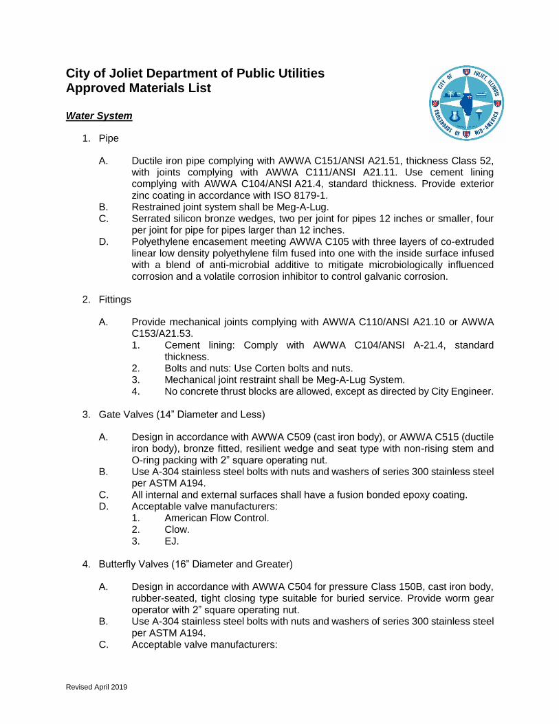
Revised April 2019
City of Joliet Department of Public Utilities Approved Materials List
Water System
1. Pipe
A. Ductile iron pipe complying with AWWA C151/ANSI A21.51, thickness Class 52, with joints complying with AWWA C111/ANSI A21.11. Use cement lining complying with AWWA C104/ANSI A21.4, standard thickness. Provide exterior zinc coating in accordance with ISO 8179-1.
B. Restrained joint system shall be Meg-A-Lug. C. Serrated silicon bronze wedges, two per joint for pipes 12 inches or smaller, four
per joint for pipe for pipes larger than 12 inches. D. Polyethylene encasement meeting AWWA C105 with three layers of co-extruded
linear low density polyethylene film fused into one with the inside surface infused with a blend of anti-microbial additive to mitigate microbiologically influenced corrosion and a volatile corrosion inhibitor to control galvanic corrosion.
2. Fittings
A. Provide mechanical joints complying with AWWA C110/ANSI A21.10 or AWWA C153/A21.53. 1. Cement lining: Comply with AWWA C104/ANSI A-21.4, standard
thickness. 2. Bolts and nuts: Use Corten bolts and nuts. 3. Mechanical joint restraint shall be Meg-A-Lug System. 4. No concrete thrust blocks are allowed, except as directed by City Engineer.
3. Gate Valves (14” Diameter and Less)
A. Design in accordance with AWWA C509 (cast iron body), or AWWA C515 (ductile iron body), bronze fitted, resilient wedge and seat type with non-rising stem and O-ring packing with 2” square operating nut.
B. Use A-304 stainless steel bolts with nuts and washers of series 300 stainless steel per ASTM A194.
C. All internal and external surfaces shall have a fusion bonded epoxy coating. D. Acceptable valve manufacturers:
1. American Flow Control. 2. Clow. 3. EJ.
4. Butterfly Valves (16” Diameter and Greater)
A. Design in accordance with AWWA C504 for pressure Class 150B, cast iron body, rubber-seated, tight closing type suitable for buried service. Provide worm gear operator with 2” square operating nut.
B. Use A-304 stainless steel bolts with nuts and washers of series 300 stainless steel per ASTM A194.
C. Acceptable valve manufacturers:

Revised April 2019
1. American Flow Control. 2. Clow. 3. EJ.
5. Insertion Valves
A. Design in accordance with AWWA C515 epoxy coated split body, resilient wedge or seat type with O-ring seal stuffing, rated for 250 psi working pressure.
B. Acceptable valve manufacturers: 1. Hydra-Stop Insta-Valve IVP 250. 2. Advanced Valve Technologies EZ2 Valve.
6. Valve Vaults
A. Provide 4’ diameter vaults for valves 10” and less. Provide 5’ diameter vaults for valves 12” and larger.
B. Provide pre-cast concrete structure with EJ 1050Z1 or Neenah R1710 frame. C. “WATER” and “CITY OF JOLIET” shall be cast into the lid. D. Install Henry Company, RN103- RAM-NEK Preformed Flexible Gasket (Coils) or
ConSeal Concrete Sealants, Inc., Type CS-102 at all joints. E. Valve vaults shall be concentric for gate valves and eccentric for butterfly valves.
7. Valve Boxes
A. American made adjustable valve boxes with “WATER” cast into lid. B. Provide stainless steel extension stems for water mains deeper than 6’. C. Acceptable Manufacturers:
1. EJ Series 8550 2. Tyler 6850 Series
D. Valve box stabilizer: 1. Alberico. 2. American. 3. Adaptor, Inc. 4. Or equal.
8. Fire Hydrants
A. Design in accordance with AWWA C502 (Dry Barrel) B. Provide compression type with a 5¼-inch minimum size main valve assembly, O-
ring seals, two 2½-inch hose nozzles, and a 4½-inch pumper nozzle with National Standard threads, a National Standard operating nut, and an above ground break flange.
C. Color for hydrants on potable distribution mains shall be red, hydrants on raw water mains shall be green. Color for private system hydrants shall be yellow.
D. Maximum spacing for fire hydrants shall be 300 feet. E. Acceptable manufacturers:
1. EJ 5BR250. 2. Clow Medallion. 3. Mueller Centurion A423

Revised April 2019
9. Tapping Sleeve
A. Use two-piece bolted sleeve ductile iron type with mechanical joints. Only under special circumstances will the stainless steel type be allowed to be substituted for the cast iron sleeve. Provide joint accessories.
B. The City of Joliet Water Department shall be responsible for completing all taps to existing water mains. Contractor will be responsible for calling 815-724-4220 to schedule an appointment with the City Water Department. Appointments are available on Tuesdays and Thursdays.
C. Acceptable manufacturer: 1. Clow F5205 2. Or equal.
10. Water Service
A. Service size 2” or less shall be Type “K” copper, installed as one continuous piece from main to curb stop. Service size 4” and larger shall be ductile iron.
B. Service saddle required for services larger than 1”: Mueller DR2A. C. Corporation stop: A.Y. McDonald 74701 BQ. D. Curb stop: A.Y. McDonald 76104Q. E. Service box: Tyler 6500 with BBAF valve box stabilizer.
Sanitary Sewer System
1. Gravity Sewer
A. For sewers less than 24-inch diameter and for depths up to 18 feet, provide SDR 26 PVC sewer pipe : 1. 4-inch through 15-inch: Comply with ASTM D3034, SDR 26. Use
elastomeric gasket type (ASTM F477 and ASTM D3212). Gaskets for fittings and joints: provide minimum cross-sectional area of 0.20 square inches (ASTM F477).
2. 18-inch through 24-inch: Comply with ASTM F679, PS-115. Use integral bell gasketed type joints with elastomeric gaskets (ASTM F477 or ASTM D3212).
3. Branch fittings: factory fabricated type with attached main line coupling. SDR 26.
4. Risers and service pipe and fittings: SDR 26, solid wall type (ASTM D3034).
B. For sewers less than 24-inch diameter and for depths greater than 18 feet and less than 25 feet, provide SDR 21 PVC sewer pipe: 1. Comply with ASTM D2241, SDR 21. 2. Use push-on bell and spigot type, or Certa-Lok spline-lock system, with
rubber ring seal gasket (ASTM D3139). 3. Branch fittings: Factory fabricated type with attached main line coupling,
with same rating as pipe. 4. Risers and service pipe and fittings: ASTM D2241, SDR 21.
C. For sewers less than 24-inch diameter and for depths greater than 25 feet, provide ductile iron pipe:

Revised April 2019
1. Comply with AWWA C151/ANSI A21.51, thickness Class 50, with joints complying with AWWA C111/ANSI A21.11.
2. Use cement lining complying with AWWA C104/ANSI A21.4, standard thickness.
3. Use Corten bolts and nuts. 4. Use mechanical restrained joint plugs and caps; Megalug. 5. Branch fittings: Factory fabricated type with attached main line coupling,
with same rating as pipe. 6. Risers and service pipe and fittings: Ductile iron until depth of 18 feet, then
SDR 26 PVC Sewer pipe. D. For sewers greater than 24-inch diameter, use reinforced concrete pipe (RCP):
1. Comply with ASTM C76, Class V. 2. Use rubber gasket with steel bell and spigots (ASTM C361 and AWWA
302); HK Hamilton Kent of Canada Limited or equal. 3. No lifting holes allowed in pipe.
E. ADS SaniTite HP pipe: 1. Only to be used with City approval for sewers greater than 15-inch diameter
and for depths less than 18 feet 2. Comply with ASTM F2736 (12” – 30”) and ASTM F2764 (30” – 60”), pipe
stiffness of 46 psi when tested in accordance with ASTM D2412 3. Use integral bell and spigot type with rubber ring seal gasket meeting
ASTM F477. 4. Polypropylene compound for pipe and fitting production shall comply with
ASTM F2736, ASTM F2764, and AASHTO M330 for respective diameters. 5. Fittings conform to ASTM F2736, ASTM F2764 and AASHTO M330
F. Fiberglass reinforced polyester pipe (FRP) and centrifugally cut fiberglass reinforced polymer mortar pipe (CCFRPM): 1. Only to be used with City approval for large diameter sewers. 2. Materials:
a. Resin system: polyester. b. Glass reinforcement: Grade E-glass filaments. c. Sand: 98 percent silica with maximum moisture content of 0.20
percent. 3. Manufacture:
a. Comply with ASTM D3262. b. Thickness: Comply with manufacturer’s recommendations. c. Stiffness: Minimum 46 psi when tested in accordance with ASTM
D2412. 4. Joints:
a. Fiberglass sleeve couplings. b. Bell and spigot. c. Elastomeric gaskets complying with ASTM F477. Joints complying
with ASTM D4161. d. Acceptable manufacturers: Hobas Pipe USA, Inc., no substitutions.
G. For water main crossings, provide pressure rated PVC or ductile iron pipe: 1. PVC pressure pipe: Use Type I, Grade 1, PVC complying with ASTM
D1784. Comply with ASTM D2241 for 160 psi pressure rated pipe, SDR 26. Use push-on bell and spigot type, or Certa-Lok spline-lock system, with rubber ring seal gasket (ASTM D3139). a. Branch fittings: Factory fabricated type with attached main line
coupling, with same rating as pipe.
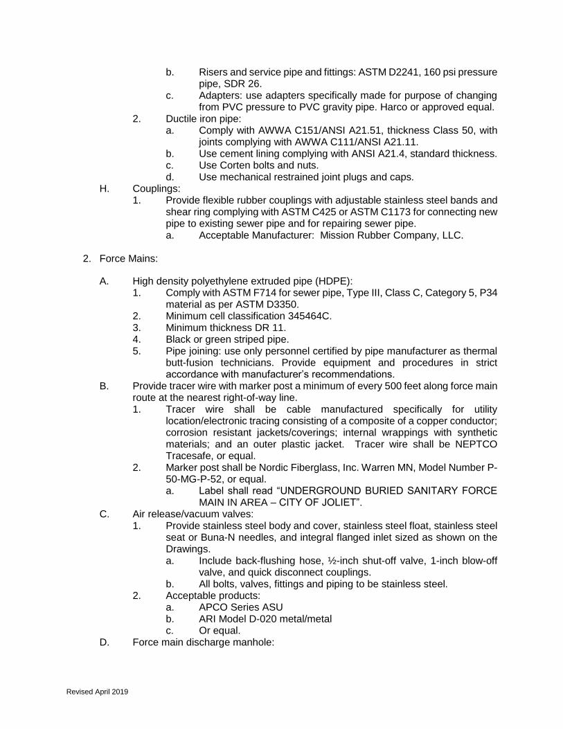
Revised April 2019
b. Risers and service pipe and fittings: ASTM D2241, 160 psi pressure pipe, SDR 26.
c. Adapters: use adapters specifically made for purpose of changing from PVC pressure to PVC gravity pipe. Harco or approved equal.
2. Ductile iron pipe: a. Comply with AWWA C151/ANSI A21.51, thickness Class 50, with
joints complying with AWWA C111/ANSI A21.11. b. Use cement lining complying with ANSI A21.4, standard thickness. c. Use Corten bolts and nuts. d. Use mechanical restrained joint plugs and caps.
H. Couplings: 1. Provide flexible rubber couplings with adjustable stainless steel bands and
shear ring complying with ASTM C425 or ASTM C1173 for connecting new pipe to existing sewer pipe and for repairing sewer pipe. a. Acceptable Manufacturer: Mission Rubber Company, LLC.
2. Force Mains:
A. High density polyethylene extruded pipe (HDPE): 1. Comply with ASTM F714 for sewer pipe, Type III, Class C, Category 5, P34
material as per ASTM D3350. 2. Minimum cell classification 345464C. 3. Minimum thickness DR 11. 4. Black or green striped pipe. 5. Pipe joining: use only personnel certified by pipe manufacturer as thermal
butt-fusion technicians. Provide equipment and procedures in strict accordance with manufacturer’s recommendations.
B. Provide tracer wire with marker post a minimum of every 500 feet along force main route at the nearest right-of-way line. 1. Tracer wire shall be cable manufactured specifically for utility
location/electronic tracing consisting of a composite of a copper conductor; corrosion resistant jackets/coverings; internal wrappings with synthetic materials; and an outer plastic jacket. Tracer wire shall be NEPTCO Tracesafe, or equal.
2. Marker post shall be Nordic Fiberglass, Inc. Warren MN, Model Number P-50-MG-P-52, or equal. a. Label shall read “UNDERGROUND BURIED SANITARY FORCE
MAIN IN AREA – CITY OF JOLIET”. C. Air release/vacuum valves:
1. Provide stainless steel body and cover, stainless steel float, stainless steel seat or Buna-N needles, and integral flanged inlet sized as shown on the Drawings. a. Include back-flushing hose, ½-inch shut-off valve, 1-inch blow-off
valve, and quick disconnect couplings. b. All bolts, valves, fittings and piping to be stainless steel.
2. Acceptable products: a. APCO Series ASU b. ARI Model D-020 metal/metal c. Or equal.
D. Force main discharge manhole:

Revised April 2019
1. Provide polymer concrete manhole sections, monolithic base sections and related components complying to ASTM C478.
2. Acceptable manufacturer: a. U.S. Composite Pipe
3. Manholes:
A. Provide pre-cast concrete structure conforming to ASTM C478 with EJ 1050Z1 frame. 1. “SANITARY” and “CITY OF JOLIET” shall be cast into the lid.
B. Pipe connections: Flexible synthetic rubber boots meeting ASTM C-923 C. Manhole diameter shall be determined by sewer outside diameter, relative angles
of sewers to each other, the size of holes cored for flexible pipe “boot” connector and a minimum of 8” between cored/cast holes. Refer to Design Manual for manhole sizing.
D. External frame seal on all new manholes shall conform to conform to ASTM C923: Infi-Shield Uni-Band or WrapidSeal CANUSA.
E. Manhole exterior joint protection: MacWrap F. Manhole exterior surface treatment: Con-Seal CS-55. G. Manhole interior protection system where indicated: Sherwin Williams DuraPlate
6100 or Raven 405. H. Grade rings: Precast Concrete
1. Maximum of two rings 2. Total height shall not exceed 12” 3. For manholes installed in pavement, one rubber composite adjustment ring
shall be provided: EJ Infra-riser or approved equal
4. Sewer System Rehabilitation
A. Cured-In-Place-Pipelining: Insituform, Inliner USA, National Liner or an approved equal. 1. Design shall comply with ASTM F-1216. 2. End Seal: “Insignia” as manufactured by LMK or equivalent
B. For CIPP installations greater than 24-inch diameter, temperature sensor cable with a minimum reading of every 5’ shall be used to ensure proper curing.
C. Manhole Patching Material: Strong Seal QSR; Quadex Hyperform; or pre-approved equal.
D. Cementitious Manhole Sealing: Strong Seal MS-2C; or approved equal. E. Visible Infiltration: Strong-Plug; Quadex Quad-Plug; or approved equal. F. Internal chimney frame seal allowed only on existing manholes as indicated on
plans: Raven 581 or SSI Flex-Seal G. Couplings for CIPP and Service Connections to CIPP:
1. Provide flexible rubber couplings with adjustable stainless steel bands and shear ring complying with ASTM C425 or ASTM C1173 for connecting new pipe to cured-in-place sewer pipe and for repairing cured-in-place sewer pipe. a. Acceptable Manufacturer: Mission Rubber Company, LLC
(Distributed by LMK Technologies, LLC.) 2. LMT Service saddle required for connecting new sewer service
connections to mainline cured-in-place sewer pipe. (Distributed by LMK Technologies, LLC.)

Revised April 2019
APPENDIX B
Standard Details


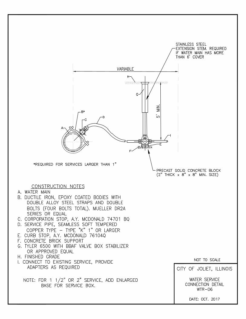


Revised April 2019
APPENDIX C
Lift Station Design Requirements

Revised April 2019
City of Joliet, IL
Standard Design for Duplex Submersible Pumping Stations
Updated: April 1, 2019
Pump Features
1a Pump type (<50 HP) duplex submersible vortex
1b Max. pump speed allowable? 3600 RPM
1c Approved Pump manufacturers: Grundfos, Flygt Econoline, Hydromatic, Barnes
or Wilo
2a Pump type (>50 HP) duplex submersible vortex
2b Max. pump speed allowable? 1200 RPM
2c Approved Pump manufacturers: Wilo or Flygt
3 Check Valves Oil Cushioned
4a Isolation Valves Plug Valves
4b Provide isolation valve upstream of check valve? Yes
4c Actuator on isolation valve Handwheel
4d Force main isolation valve after valve vault? Yes
5a Size of quick disconnect for portable pump Plain End - Review with Operations
Superintendent
5b Provide a "Porta-Con" connection in valve vault slab? Not unless required by IEPA
5c Provide a "Porta-Con" connection in wetwell? Not unless required by IEPA
6 Plug valve manufacturers DeZurik or Valmatic
7 Flanged Piping requirements Class 53 DI w/ SS bolts
Electrical + Control System Decisions
1a Wetwell level sensing Radar Sensor, Vega PULS WL61
1b Stilling well for level sensor? No
2 Control Panel type NEMA 4x stainless
3 Phase Seq. Monitor/Relays? (undervoltage, phase loss)
Yes
4 Motor High Temperature Alarm local visual in panel (req'd)
5 Seal Failure Alarm local visual inside panel
6 High Water Alarm local visual in panel (req'd)
7a Proof of flow required? (limit switch on check valves to detect when stuck open)
No (can be a nuisance issue)
7b Use a common alarm instead of individual alarms ? No
8a Standby Generator? Yes - Fixed natural gas preferred

Revised April 2019
8b If fixed, locate inside building? No - metal housing
8c Generator Manufacturers Caterpillar or Cummins
8d For a fixed generator, type of transfer switch Automatic
9 Pump speed control ? VFDs
10a What VFD mfgrs to specify? ABB, Danfoss, or Allen Bradley
10b Bypass Contactor on VFD? Yes, on at least one pump when pumps are
greater than 50 HP
10c Air conditioner in VFD cabinet? Yes
11 SCADA Micrologix 1400, must specify City's preferred
integrator
12 PLC manufacturers Allen Bradley
13 Flow measurement Mag Meter (ABB or Siemens)
14 Ground fault protection (req'd) … Equipment + personnel
15 Surge/lightning arrestor Yes
16a Pressure gauges on force main Yes - diaphragm seal type
16b Continuous FM pressure monitoring + alarming? Yes for pumps greater than 50 HP
17 Locate controls & elec in air conditioned NEMA 4X stainless steel outdoor panels
Yes, for standard duplex submersible pump
station.
18 Locate controls & elec in NEMA 1 enclosures in a single package building
TBD on case by case basis for larger stations
Accessories
1 Method to remove pumps Crane Truck
2 Lifting cable stainless steel chain-316
3 Guide rails stainless steel-316
4a Access Hatch locking device Hasp in floor
4b Access Hatch load strength H-20
5 Fall protection for hatch safety grate
6 Debris basket No
7a Wetwell & FM Discharge MH (New) Polymer Concrete Structure, US Composite
Pipe
7b Wetwell & FM Discharge MH (Existing) Sherwin Williams DuraPlate 6100 or Raven 405
8 Discharge Piping Link Seal required where pipe exits wet well
9 Wetwell Backfill For wetwells deeper than 15 feet, CLSM is
required for backfill up to 10 feet below grade.
10 Driveway type asphalt
11 Fencing No

Revised April 2019
12 Provide sump pumps in valve vault + mag meter vault?
Yes - sump only, City to provide pump
13 Provide permanent ventilation in valve vault/meter vault?
Yes - fixed
14 Conc filled Bollards at station+valve vault? Yes, painted yellow
15 Intrusion Alarms? No
16 Site Lighting? Depends on Location. If Residential, no. If Industrial/Commercial provide pole mount,
photocell lighting
17 Sampler Required No
18 Need to provide potable water service into the site? No
19 Odor Control TBD on case by case basis. System shall be
non-passive, forced air

Revised April 2019
APPENDIX D
General Notes

Revised April 2019
CITY OF JOLIET WATER & SEWER SYSTEM GENERAL NOTES
1. VERIFY LOCATION, SIZE, AND DEPTH OF ALL EXISTING UTILITIES
PRIOR TO CONSTRUCTION. THE LOCATIONS OF EXISTING UTILITIES
AS SHOWN ON THE DRAWINGS HAVE BEEN DETERMINED FROM THE
BEST AVAILABLE INFORMATION AND IS GIVEN FOR THE
CONVENIENCE OF THE CONTRACTOR. THE ENGINEER AND OWNER
DO NOT ASSUME RESPONSIBILITY FOR THE ACCURACY OF THE
LOCATION SHOWN. IT SHALL BE THE CONTRACTOR’S
RESPONSIBILITY TO CONTACT ALL UTILITY COMPANIES AND LOCATE
UTILITIES PRIOR TO ANY WORK.
2. WHEREVER OBSTRUCTIONS NOT SHOWN ON THE DRAWINGS ARE
ENCOUNTERED DURING THE PROGRESS OF THE WORK AND
INTERFERE TO SUCH AN EXTENT THAT ALTERATIONS TO THE
DRAWINGS ARE REQUIRED, THE ENGINEER SHALL BE NOTIFIED
PRIOR TO ANY CHANGES.
3. HORIZONTAL AND VERTICAL SEPARATION OF WATER MAINS AND
SEWER LINES SHALL BE DONE IN ACCORDANCE WITH THE LATEST
EDITION OF THE “STANDARD SPECIFICATION FOR WATER AND
SEWER CONSTRUCTION IN ILLINOIS”.
4. PROVIDE PROPERTY OWNERS ADVANCE NOTICE OF CONSTRUCTION
ACTIVITIES THAT WILL RESTRICT THE USE OF THEIR DRIVEWAYS.
5. DO NOT STORE BEDDING AND BACKFILL MATERIALS, PIPES,
FITTINGS, VAULTS, OR OTHER MATERIALS IN AREAS THAT WILL
OBSTRUCT SIGHT LINES FOR STREETS AND DRIVEWAYS.
6. ALL PROPOSED UTILITIES UNDER AND WITHIN 2’ OF PAVEMENT OR
SIDEWALK SHALL BE BACKFILLED WITH TRENCH BACKFILL WHICH
SHALL BE CRUSHED STONE, GRADATION CA 6 OR CA 7.
7. ALL MATERIALS SHALL BE IN ACCORDANCE WITH THE CITY OF JOLIET
DEPARTMENT OF PUBLIC UTILITIES APPROVED MATERIALS LIST,
LATEST EDITION
8. INSTALL NEW WATER MAIN WITH A MINIMUM OF 5’ COVER BELOW
EXISTING OR PROPOSED GROUND SURFACE UNLESS GREATER
DEPTH IS REQUIRED TO AVOID EXISTING UTILITIES OR WHERE
INDICATED ON THE DRAWINGS.

Revised April 2019
9. PROVIDE 48 HOURS ADVANCE NOTICE TO THE CITY WHEN
CONNECTION TO AN EXISTING WATER MAIN WILL BE MADE.
COORDINATE SHUTDOWN OF EXISTING WATER MAINS WHEN
REQUIRED WITH THE CITY. SCHEDULE THE WORK TO MINIMIZE THE
NUMBER AND LENGTH OF SHUTDOWNS. PROVIDE WRITTEN
NOTIFICATION OF SHUTDOWNS TO WATER USERS AFFECTED 24
HOURS IN ADVANCE.
10. NOTIFY THE CITY’S PUBLIC UTILITIES DEPARTMENT IMMEDIATELY IF
EXISTING LEAD WATER SERVICES ARE DISCOVERED.
11. LOCATE PRESSURE CONNECTIONS, IF INDICATED ON THE DRAWINGS
OR WHEN DIRECTED BY THE ENGINEER, A MINIMUM OF 2’ FROM ANY
EXISTING REPAIR SLEEVES OR PIPE JOINTS.
12. PROVIDE A TEMPORARY COVERING OVER ALL NEW FIRE HYDRANTS
UNTIL ALL NEW WATER MAINS ARE PUT INTO SERVICE AND NEW FIRE
HYDRANTS ARE OPERABLE.
13. SUCCESSFULLY TEST, DISINFECT, AND FLUSH WATER MAIN, AND
OBTAIN ACCEPTANCE OF THE WATER MAIN BY THE CITY OF JOLIET,
PRIOR TO MAKING WATER SERVICE CONNECTIONS. FLUSH
PIPELINES TO OBTAIN A VELOCITY OF 2.5 FT/S PER AWWA STANDARD
C651.
14. SEWER TESTING, CLEANING, AND TELEVISING REQUIREMENTS: ALL
SANITARY SEWER MAINS SHALL BE DEFLECTION TESTED AND AIR
TESTED PER THE LATEST EDITION OF THE “STANDARD
SPECIFICATIONS FOR WATER AND SEWER CONSTRUCTION IN
ILLINOIS”. ALL NEWLY CONSTRUCTED SEWER MAINS SHALL BE
CLEANED AND TELEVISED PRIOR TO BEING PUT INTO SERVICE.
15. USE RESTRAINED MECHANICAL JOINT FITTINGS WITH MEGALUG TO
PLUG/CAP EXISTING WATER MAINS TO REMAIN IN SERVICE AND FOR
EXISTING WATER MAINS TO BE ABANDONED. PLUGS/CAPS ON
WATER MAIN TO REMAIN IN SERVICE SHALL INCLUDE AN
ADEQUATELY SIZED CAST-IN-PLACE CONCRETE THRUST BLOCK AS
DIRECTED BY THE CITY.
16. PAVEMENT RESTORATION WILL BE MEASURED IN PLACE AND THE
AREA COMPUTED IN SQUARE YARDS. ALL AREAS DISTURBED WILL
BE REPLACED, BUT THE MAXIMUM ALLOWABLE WIDTHS USED FOR
PAY QUANTITY CALCULATIONS WILL BE 6 FEET CENTERED ON THE

Revised April 2019
PIPE. IF THE CONTRACTOR RELOCATES THE TRENCH AWAY FROM
THE CURB AND GUTTER, THE PAVEMENT PATCH WILL EXTEND FROM
THE SAWCUT IN THE EXISTING PAVEMENT TO THE FACE OF THE
GUTTER AND THE MAXIMUM ALLOWABLE WIDTH OF 6 FEET WILL BE
USED FOR PAY QUANTITY CALCULATIONS.
17. REPLACE ALL CONCRETE SIDEWALKS DISTURBED BY
CONSTRUCTION TO THE NEAREST CONSTRUCTION JOINT. A
MAXIMUM LENGTH OF TEN LINEAL FEET PER CROSSING WILL BE
UTILIZED FOR PAY QUANTITY CALCULATIONS.
18. AS-BUILT DRAWINGS SHALL BE PREPARED BY THE CONTRACTOR
AND SUBMITTED TO THE ENGINEER AS SOON AS THE PROJECT IS
COMPLETED. ANY CHANGE IN THE LENGTH, LOCATION, OR
ALIGNMENT SHALL BE SHOWN IN RED.
19. EROSION CONTROL WILL BE CONSTRUCTED IN ACCORDANCE WITH
STANDARD SPECIFICATIONS FOR SOIL EROSION AND SEDIMENT
CONTROL AS CONTAINED IN IEPA/WPC/87-012 OR CURRENT EDITION.
20. THE CITY OF JOLIET WATER DEPARTMENT SHALL BE RESPONSIBLE
FOR COMPLETING ALL TAPS TO EXISTING WATER MAINS.
CONTRACTOR WILL BE RESPONSIBLE FOR CALLING 815-724-4230 TO
SCHEDULE AN APPOINTMENT WITH THE CITY WATER DEPARTMENT.
APPOINTMENTS ARE AVAILABLE ON TUESDAYS AND THURSDAYS.
21. IT SHALL BE THE CONTRACTOR’S DUTY AND RESPONSIBILITY TO
ASCERTAIN AND EXECUTE THE MEANS, METHODS, AND SEQUENCE
OF CONSTRUCTION IN ACCORDANCE WITH THE DRAWINGS,
SPECIFICATIONS, AND OTHER CONTRACT DOCUMENTS. THIS SHALL
INCLUDE, BUT SHALL NOT BE LIMITED TO, THE EXCLUSIVE DUTY AND
RESPONSIBILITY TO PROVIDE FOR WORKPLACE SAFETY AND
WORKER SUPERVISION. IT SHALL EXCLUSIVELY BE THE
CONTRACTOR’S DUTY AND RESPONSIBILITY TO INVESTIGATE AND
ASCERTAIN THE CURRENT PHYSICAL STATE AND OPERATIONAL
STATUS OF THE CITY’S WATER SUPPLY SYSTEM AND THE CITY’S
SANITARY SEWER SYSTEM, INCLUDING WHETHER A WATER MAIN OR
OTHER VESSEL IS OPERATIONAL, CONTAINS WATER, IS
PRESSURIZED, OR IS OTHERWISE SAFE TO ALTER. ANY
INFORMATION PROVIDED BY THE CITY, OR ITS EMPLOYEES AND
CONSULTANTS, REGARDING THE STATE OF ITS WATER SUPPLY AND
SANITARY SEWER SYSTEMS IS PROVIDED AS A COURTESY TO THE
CONTRACTOR BUT IS NOT WARRANTED TO BE TRUE AND MAY NOT

Revised April 2019
BE RELIED ON BY THE CONTRACTOR IN SATISFACTION OF, OR TO
DIMINISH, ITS EXCLUSIVE DUTY TO ASCERTAIN AND EXECUTE THE
MEANS, METHODS, AND SEQUENCES OF CONSTRUCTION IN
ACCORDANCE WITH THE DRAWINGS, SPECIFICATIONS, AND OTHER
CONTRACT DOCUMENTS AND ITS EXCLUSIVE RESPONSIBILITY TO
PROVIDE FOR WORKPLACE SAFETY AND WORKER SUPERVISION.
22. WATER SERVICE INSTALLATION WORK MUST BEGIN WITHIN 7 DAYS
OF IEPA APPROVAL. FINAL PAVEMENT RESTORATION MUST BE
COMPLETED WITHIN 21 DAYS AFTER THE LAST COMPLETED WATER
SERVICE CONNECTION ON ANY ONE STREET OR MOVING THE
EXCAVATION CREW AND EQUIPMENT TO ANOTHER STREET. THE
CONTRACTOR HAS THE OPTION TO INSTALL TEMPORARY PAVEMENT
AT NO ADDITIONAL COST TO THE CITY WITHIN 7 CALENDAR DAYS.
THE CITY CAN STOPE OPERATIONS UNTIL TEMPORARY PAVEMENT IS
PLACED OR PERMANENT PAVEMENT RESTORATION IS COMPLETE.

Revised April 2019
APPENDIX E
Pretreatment Questionnaire

City of Joliet – Service Area Wastewater and Pretreatment Survey
12/2018 SNS
Company Name: _____________________________________________________
Address: _____________________________________________________
City, State, Zip: _____________________________________________________
Site Representative: _____________________________________________________
Title: _____________________________________________________
Site Phone: _____________________________________________________
Email: _____________________________________________________
Number of units in building occupied by this company: Stand-alone building □ Multiple Units: □ # of Units: ______
Number of Employees: _______ 1st Shift _______ 2nd Shift _______ 3rd Shift Operating Days: □ Mon □ Tues □ Wed □ Thurs □ Fri □ Sat □ Sun
Operating Hours Per Day (Mon-Fri): ________ (Sat-Sun): ________
Date That Service / Production Began at this site: Month___________ Year __________
What services are performed or products produced at this site?
__________________________________________________________________________________________________________________________________
What raw materials are used on site?
__________________________________________________________________________________________________________________________________ Does your business do manufacturing at this facility? □ Yes □ No
Does your business do assembly or fabrication at this facility? □ Yes □ No
Does your business have an office at this facility? □ Yes □ No
Does your business have a warehouse at this facility? □ Yes □ No
Does your business have a cafeteria that prepares meals at this facility? □ Yes □ No
Does your business discharge process wastewater (non-domestic) to the sewer? □ Yes □ No
Description of process waste discharged: ____________________________________________________________________________________
Does your business treat your discharge at any point within your process? □ Yes □ No
Does your business have any process waste hauled offsite? □ Yes □ No
Description of process waste hauled: _________________________________________________________________________________________
Does the firm store liquids in drums (typically 55 gal.)? □ Yes □ No If yes, how many drums: Less Than 5 drums: □ 5 or more drums: □
Drum general substance: _______________________________________________________________________________________________________
Does the firm store liquids in totes or bulk tanks? □ Yes □ No If yes, how many totes: __________ How many bulk tanks: __________
Tote or bulk tank general substance and number of gallons: _______________________________________________________________
Does your facility use any materials which include, but are not limited to, cleaning products, raw materials or chemicals in a process which contain PHOSPHOROUS in the ingredients? □ Yes □ No
Are any inks or dyes used: □ Yes □ No If yes, are any inks or dyes washed down the drain: □ Yes □ No
Does your firm precondition your water? □ Yes □ No If yes, check how: □ Water Softener □ Reverse Osmosis □ Ion Exchange □ Distilled
Does your business have laundry facilities on site? □ Yes □ No
Do you have a backflow preventer? □ Yes □ No
Complete this form with the values for
each item anticipated to exist when the
business is in operation.

Revised April 2019
APPENDIX F
Critical Customer Questionnaire

City of Joliet – Critical Customer Questionnaire
Physical Building Details
Building Name:
Address:
Address Line 2 (optional):
ZIP/Postal Code
1. Emergency contact information
Company:
Job Title:
Name:
Phone:
Email:
2. Alternate Emergency contact information
Job Title:
Name:
Phone:
Email:
3. If there is a building engineer; please provide contact information
Job title:
Name:
Phone:
Email:
4. Please select facility that corresponds to your facility type. If you select other, please describe why the
property is designated as critical, including description of potential impacts from water or sewer
disruption.
Hospitals/Medical Centers (including dialysis centers)
Nursing Homes/Assisted Living/Homeless Shelters
Universities/High Schools/Middle Schools/Elementary/Preschools/Day Care Centers
Public Shelters/Cooling Centers/Pools
First Responder Organizations/Police/Fire/EMTs

City of Joliet – Critical Customer Questionnaire
Power Providers
Potable Water Haulers
State/Local Emergency Management Agencies
Local/Federal Government Facilities necessary for public safety/health
Mass Transit Stations
Radio/TV Broadcast Centers
Other (please specify)
5. Describe operational impacts if water is available for flushing toilets and cleaning but not for
consumption purposes.
for less than 24 hours
for greater than 24 hours
6. Describe operational impact if water is not available due to a construction or distribution system.
failure for less than 24 hours
failure for greater than 24 hours
7. If you have a written emergency or contingency plan that establishes how long the property can operate
with limited or reduced water/sewer services, how long is your contingency period?
8. If there is an individual at your organization who is responsible for emergency planning, please provide
contact details:
Job title:
Name:
Phone:
Email:

City of Joliet – Critical Customer Questionnaire
9. What is the total occupancy served by your property’s water system? (e.g. number of employees, number
of residents, number of visitors, and number of buildings)?
10. If your property serves a vulnerable population (e.g. ill, elderly, children), please describe the population
type and quantity of people.
11. If your property provides a vital public health or public safety purpose, please describe.
12. If you have potable water storage tanks onsite, please indicate the volume of onsite potable water
storage.
13. If you have bottled water stored onsite, please indicate how much bottled water is stored onsite.
14. Do you have a vendor agreement or shared services agreement with another property for emergency
potable/non potable water resupply?
□ Yes □ No
15. If you have a supply of portable toilets, what is the quantity?
16. If you have an emergency power source, such as a generator or quick connect for a generator, please
describe.
17. What is your City of Joliet Water Account Number (located on bill)?
18. If your organization has more than one City of Joliet account, please provide account numbers:
19. Is there any other information that you want to share with City of Joliet regarding emergency
water/sewer impacts on your property or facilities?