
Utilisation of geothermal resources
20
Articles: Categorisation of geothermal areas District heating in Reykjavík Hellisheiði Power Plant and hot water main Reykjanes power plants Svartsengi Resource Park Snow melting in Reykjavík Special edition Utilisation of geothermal resources Consulting Engineers
Transcript of Utilisation of geothermal resources

Articles:
Categorisation of geothermal areas
District heating in Reykjavík
Hellisheiði Power Plant and hot water main
Reykjanes power plants
Svartsengi Resource Park
Snow melting in Reykjavík
Special edition
Utilisation of geothermal resources
C o n s u l t i n g E n g i n e e r s

Gangverk Verkís hf Newsletter Special Edition2011
Publisher: Verkís hf
Editor Sveinn I. Ólafsson
Copy editing and design: Rafn Sigurbjörnsson
Printing: Hjá Guðjón Ó
Photographs: Rafn Sigurbjörnsson, Skarphéðinn Þráinsson and staff of Verkís
Cover photo: Geothermal Power Plant at SvartsengiRafn Sigurbjörnsson Dec. 2010
Use of material from this newsletter entirely or partly is permitted with the condition that the source is quoted
Ármúli 4, 108 Reykjavík Iceland
This special issue of the Verkis newsletter Gangverk is devoted to geothermal energy.
Geothermal heat is a major energy source in Iceland and one of the nation’s most valuable natural resources. The following articles provide an overview of the multiple methods of geothermal heat utilisation in Iceland. They describe large scale district heating systems and geothermal power plants producing electricity as well as combined heat and power.
We at Verkis hope that readers will enjoy this overview of geothermal utilisation in Iceland. We are also hoping that it will inspire investigation and utilisation of geothermal resources elsewhere.
Icelanders have used hot spring water for washing and bathing since the middle ages and for space heating on a large scale from the middle of the twentieth century. Today the vast majority of housing in Iceland is heated with hot water which is either pumped directly from low temperature geothermal fields or heated with geothermal steam from high temperature fields. This is of great economic importance as well as a significant environmental benefit.
Gangverk
Sveinn Ingi ÓlafssonGeneral [email protected]
© Daniel Dalet / d-maps.com
Hydro PowerGeothermal PowerBranch officeOther activities
Guadeloupe
GreenlandIceland
Poland
Slovakia
Bulgaria
Turkey
Georgia
India
China
Kamchatka
Gaza
Kenya
Djibouti
Indonesia
MaltaAzores
U.S.A.
Alaska
Hungary
Norway
Icenet Sweden
Ukraine
Switzerland
Netherlands
DominicaEl Salvador
Chile
2

Verkis has been a major contributor to the technical development of geothermal energy production and distribution in Iceland for over fifty years. The company’s geothermal specialists have worked continuously on development and design of geothermal power plants for the last two decades. Verkis can thus offer geothermal specialists with up to date knowledge and relevant worldwide experience. The company’s specialists have accumulated wide ranging experience at home and abroad and can offer expert advice on the use of geothermal energy for heating, power production and industrial applications.
If imported oil were used for heating of space and domestic water instead of geothermal heat, Iceland’s carbon emissions would be 50% greater and the resulting oil bill would amount to almost 500 million USD per year.
Currently there is widespread interest in utilising geothermal heat as an energy source. Governments and companies around the world are exploring geothermal resources. Much of the interest is focused on the production of electricity, which relates in most part to the relative ease of transporting and selling that form of energy. However, the direct use of geothermal heat for space heating or industrial applications should not be overlooked.
Gunnar Ingi GunnarssonForeign business [email protected]
© Daniel Dalet / d-maps.com
Hydro PowerGeothermal PowerBranch officeOther activities
Guadeloupe
GreenlandIceland
Poland
Slovakia
Bulgaria
Turkey
Georgia
India
China
Kamchatka
Gaza
Kenya
Djibouti
Indonesia
MaltaAzores
U.S.A.
Alaska
Hungary
Norway
Icenet Sweden
Ukraine
Switzerland
Netherlands
DominicaEl Salvador
Chile
3
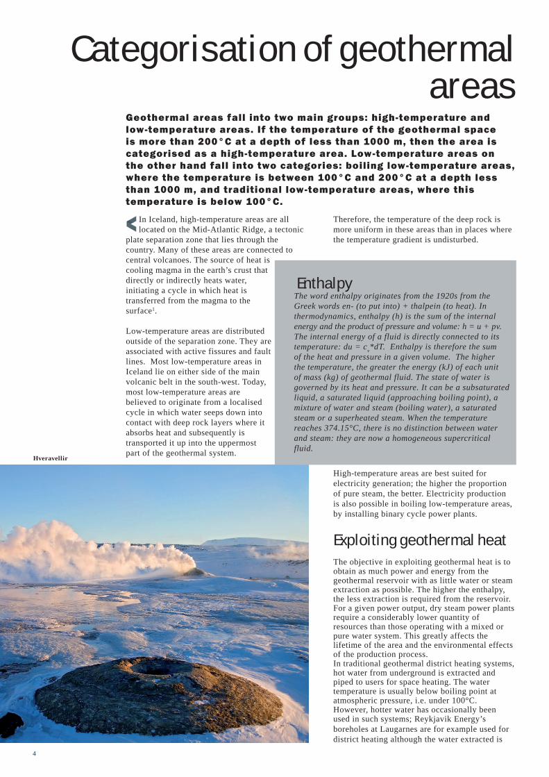
Geothermal areas fall into two main groups: high-temperature and low-temperature areas. If the temperature of the geothermal space is more than 200°C at a depth of less than 1000 m, then the area is categorised as a high-temperature area. Low-temperature areas on the other hand fall into two categories: boiling low-temperature areas, where the temperature is between 100°C and 200°C at a depth less than 1000 m, and traditional low-temperature areas, where this temperature is below 100°C.
Therefore, the temperature of the deep rock is more uniform in these areas than in places where the temperature gradient is undisturbed.
High-temperature areas are best suited for electricity generation; the higher the proportion of pure steam, the better. Electricity production is also possible in boiling low-temperature areas, by installing binary cycle power plants.
Exploiting geothermal heatThe objective in exploiting geothermal heat is to obtain as much power and energy from the geothermal reservoir with as little water or steam extraction as possible. The higher the enthalpy, the less extraction is required from the reservoir. For a given power output, dry steam power plants require a considerably lower quantity of resources than those operating with a mixed or pure water system. This greatly affects the lifetime of the area and the environmental effects of the production process.In traditional geothermal district heating systems, hot water from underground is extracted and piped to users for space heating. The water temperature is usually below boiling point at atmospheric pressure, i.e. under 100°C. However, hotter water has occasionally been used in such systems; Reykjavik Energy’s boreholes at Laugarnes are for example used for district heating although the water extracted is
In Iceland, high-temperature areas are all located on the Mid-Atlantic Ridge, a tectonic
plate separation zone that lies through the country. Many of these areas are connected to central volcanoes. The source of heat is cooling magma in the earth’s crust that directly or indirectly heats water, initiating a cycle in which heat is transferred from the magma to the surface1.
Low-temperature areas are distributed outside of the separation zone. They are associated with active fissures and fault lines. Most low-temperature areas in Iceland lie on either side of the main volcanic belt in the south-west. Today, most low-temperature areas are believed to originate from a localised cycle in which water seeps down into contact with deep rock layers where it absorbs heat and subsequently is transported it up into the uppermost part of the geothermal system.
Categorisation of geothermal areas
Hveravellir
EnthalpyThe word enthalpy originates from the 1920s from the Greek words en- (to put into) + thalpein (to heat). In thermodynamics, enthalpy (h) is the sum of the internal energy and the product of pressure and volume: h = u + pv. The internal energy of a fluid is directly connected to its temperature: du = cv*dT. Enthalpy is therefore the sum of the heat and pressure in a given volume. The higher the temperature, the greater the energy (kJ) of each unit of mass (kg) of geothermal fluid. The state of water is governed by its heat and pressure. It can be a subsaturated liquid, a saturated liquid (approaching boiling point), a mixture of water and steam (boiling water), a saturated steam or a superheated steam. When the temperature reaches 374.15°C, there is no distinction between water and steam: they are now a homogeneous supercritical fluid.
4

Oddur B. BjörnssonDepartment manager / Mechanical [email protected]
almost at 130°C. In this case, the hot water is kept under pressure until it is mixed directly with water returned from the distribution system. The heated water is then piped to homes at a temperature of around 80°C. Typically, the water utilised for district heating systems in Iceland is at least 60°C. If the extracted water temperature is lower than this it must be increased. Heat pumps may then also be considered as an alternative. Using hot water for space heating and then possibly for melting snow is the most efficient way of utilising this resource. Hot water at a temperature of 80°C that is utilised down to 30°C on average over a whole year results in 75% utilisation efficiency when comparing to the theoretical utilisation that could be achieved if it were utilised until it reached the Icelandic ambient temperature of 10-15°C.
Utilisation and efficiencyChemical engineer Baldur Líndal classified the utilisation potential of geothermal heat according to a temperature scale. He created a chart that is now recognised by geothermal operatives all
over the world. The chart depicts the utilisation potential for various industrial applications, in addition to the more traditional utilisation such as for bathing, heating greenhouses, space heating and electricity generation. Electricity production in high-temperature areas tops the scale, while geothermal energy utilisation for fish farming is situated at the lower end of the chart.In geothermal district heating systems the main emphasis is utilising the water in the best possible way. This requires i.a. that the space heating systems in the buildings and houses connected to the system are productive and effective, and return the run-off water at a low temperature. Since indoor temperature is commonly 20–22°C, water for space heating can scarcely be utilised below 30-35°C. The run-off water at such temperatures can be utilised further for bathing, soil heating or snow melting. Thus, there are various ways of improving the utilisation efficiency of the district heating water.Cascaded use of geothermal heat is an attempt to arrange varying modes of utilisation in line with Baldur Líndal’s chart. The objective is to achieve optimal utilisation of the geothermal fluid. Examples of this arrangement in Iceland are the
power plants at Svartsengi and Nesjavellir, where the hot water co-generated with electricity production is utilised for district heating. Another example is the town of Húsavík, which plans a range of uses of 120°C hot water from a nearby geothermal area. The principal use is electricity production, followed by industrial drying, space heating, bathing and fish farming.
1Jarðhitabók (The Geothermal Energy Book) Nature and utilisation of resources by Guðmundur Pálmason, Publ. The Icelandic Literary Association
EfficiencyIn the context presented here, efficiency refers to the extent to which the primary energy of a particular energy resource is harnessed to produce usable energy. As stated elsewhere, geothermal energy reserves are expressed using the concept of enthalpy, which tells us how much energy (kJ) there is in each kg of geothermal fluid (water or steam). But this is only half of the equation. The other half concerns the enthalpy that remains in the fluid (water) once processed, as this fluid is returned back into nature. It is this difference between the enthalpy entering the process and the enthalpy exiting the process that is of paramount importance. In ideal circum-stances, processed water is released at a temperature close to the ambient temperature, or about 5–10°C above the tem-perature of the local environment. Theoretically, the greatest efficiency (exergy) is achieved when the return temperature is precisely the same as the ambient temperature.
Fimmvörðuháls
Overview of potential use of geothermal energy (based on a chart created by chemical engineer Baldur Líndal)
5

District heating in Reykjavík can be traced back to the year 1930, when 70 buildings and two swimming pools were connected to
a hot water distribution system supplied by a borehole in nearby Laugardalur. The next major step occurred late 1943 when the hot water utility at Reykir in the Reykjavík suburb of Mosfellsbær was put into operation. This facility supplied most of the Reykjavík area at that time. The district heating system expanded somewhat during the following years. For example, water from wells in Mosfellsdalur and other nearby sites was piped to the pumping station at Reykir, then onwards
to the city through the Reykir main pipeline.A number of boreholes were drilled within the Reykjavík city limits after 1955. However, the district heating system did not expand at the same rate as the city and a growing number of new buildings
were heated using oil. In 1961, the population of Reykjavík was 72 000. Over 40 000 were connected to the district heating system, but over
30 000 or 44% of the residents were not.
The city set up a committee in 1954 to find ways to expand the district heating system.
In 1958 Jóhannes Zoëga became chairman of the committee. The committee completed its work in 1961 when city officials approved a proposal to extend the district heating system to cover the area of the city west of the River Elliðaá by the end of 1965. The previous year the city had purchased a new geothermal drilling rig at the recommendation of the committee.
The authorities’ decision in 1961 marked the start of a 15-year development programme which culminated in all buildings in the Reykjavík area having access to a district heating system that supplied them with hot water for space heating and hot domestic tap water use. Since then, district heating pipelines have been laid alongside other utilities’ supply lines during the development of new residential areas.
In order to realise their objective, the municipal authorities needed more than just a new, large drilling rig. Extensive changes were required to the processing of the geothermal fluid, as well as to the design of the supply system. The most important modification was to start pumping the geothermal fluid out of the borehole. This led to lowering of the groundwater level in the production area, which in turn caused an influx of hot water into it. Water was no longer taken
from the surface – it was pumped from a depth of 100–200 m. The amount of water obtained from the production area for processing increased sixfold. At first, pumping was only conducted for the boreholes located in Reykjavík, but after 1970 pumping also began in Mosfellsbær. Table 1 shows the maximum yield of the geothermal areas before and after the changes in production methods. This increase in production amounted to more than 430 MW annually equivalent to a supply of 250 000 tonnes of oil. These changes had the environmental effect that surface formations or hot springs disappeared in both Reykjavík and Mosfellsbær. Assessments indicate that production is completely self-sustaining, the new water table level within the area and the water temperature are both fully stable.
Pumping from boreholes did however present some problems. The first pumps installed in the boreholes did not operate very well, and soon broke down. Continual disruption of the water supply led to much criticism in the press of the manager of the hot water utility. A workable pump mechanism was finally developed and is still in use today. The design was the result of a collaboration between an American pump manufacturer, employees of Reykjavík Energy and its consultants. The utility’s manager Jóhannes Zoëga is considered to have played the most significant role in the development of this solution.
In addition to pumping more water from the old production areas, drilling was begun in a new area in Reykjavík, Elliðadalur, and a 90 MW boiler station was built for peak load during periods of intense cold and for backup purposes.
This additional production allowed the utility to further expand the district heating system and by 1965 all homes and businesses in Reykjavík
District heating in the Reykjavík area
Pumping station and hot water accumulating tank at Reykir in Mosfellssveit
Table 1. Maximum yield of geothermal areas with gravity f low and with pumping
Jóhannes Zoëga
Figure 2
Heating utility installation
6

were connected, in line with earlier policy. Ten years later, the service had been extended to all neighbouring communities.The geothermal areas in Mosfellsbær and Reykjavík provided for the whole greater Reykjavík area until 1990, when hot water from the Nesjavellir power plant was added to the system’s supply. Production of hot water at the Hellisheiði power plant began in December 2010. Figure 2 shows the heat power supplied by the district heating system after the first phase of
the Hellisheiði power plant came on stream. The figures are based on hot water utilisation down to 30°C. The total power output of the hot water utility is 1200 MW, making it the world’s largest geothermal district heating system.Low-temperature hot water from the geothermal areas in Reykjavík and Mosfellsbær is used directly in the distribution system, and most consumers use it directly for their domestic heating systems and for hot tap water. Figure 3 shows a simplified schematic diagram of the section of the district heating system that operates on low-temperature hot water.
Water from these boreholes is at a temperature range of 80–127°C. Pumps located in the boreholes at depths of up to 200 m are driven by motors housed in borehole sheds. Pump axles can thus be up to 200 m long. The water is routed through a gas separator where incondensable gas is removed. The geothermal fluid contains very little gas and it is easily extracted. The water is piped from the boreholes to the distribution stations (pumping stations) and from there to consumers. The
pressure in the distribution system at each station is determined by the distance between the station and the consumers and the elevation of the distribution system served by the respective station. The pressure is either fixed or variable according to demand (water use), and it is controlled by speed-controlled pumps and/or control valves. Part of the distribution system is double, i.e. containing a supply pipe and a return pipe. Water from the boreholes is mixed with the return water so that the supply is always at a temperature of 80°C when it leaves the pumping stations. Mixing is controlled by speed-controlled pumps and/or control valves.
Sigþór Jóhannesson Division manager / Civil engineer [email protected] Nesjavellir Power
Plant
Figure 3
Borehole pumpsThe first pumps installed in Icelandic district heating boreholes were beset with problems. The pumps were located at a depth of 100 m, with motors installed above the surface. A 100 m long shaft connected each motor with its pump. The shafts were fitted with bearings at intervals of three metres. The bearings were in turn fitted with stiffeners reaching to the pipe’s walls. The temperature of the water was over 120°C, and it contained sand and other impurities. The bearings did not withstand the heat and sand, and they soon wore out. They were replaced with oil-lubricated bearings, but the result was the same. The solution was to lubricate the bearings with hot water. The shaft and bearings are sheathed in a lubricating pipe. The Teflon bearings have a slot on the shaft-facing side. Hot water is filtered and pumped down the lubricating pipe, through the slots in the bearings and then out into the borehole. This Icelandic pump design has now been in use for 45 years, with excellent results.
Reykjavík
7

The Nesjavellir and Hellisheiði power plants produce hot water for the district heating system. The fluid extracted from boreholes at these sites contains high levels of dissolved minerals, especially silica. If that water were to enter the utility’s distribution system, silica deposits would soon cause blockages in the pipes. For this reason, fresh water is pumped from wells and
heated in the power plants. Figure 4 shows a simple schematic diagram of the section of the district heating system supplied by the power plants.Cold water is pumped from wells to the power plant. First, it goes through the condenser where it condenses steam from the plant’s
turbines. This heats the water to 30–40°C. The water is then pumped through a heat exchanger that brings its temperature up to 85–100°C, using hot water from the steam separators. Finally, the water is de-gassed through boiling to remove oxygen before it is pumped to the utility’s distribution stations, where it is then cooled to 80°C by mixing with return water. After leaving the power plants the water from these stations is handled in exactly the same way as the low-temperature hot water that has passed through a steam separator.The mineral content of water from low-
temperature areas and heated water from power plants differs. Low-temperature hot water is saturated with silica, while power plant water contains magnesium. If these water types are mixed, magnesium silicate is deposited on the inside of pipes, greatly reducing their flow capacity. It is therefore necessary to operate two separate hot water supply systems in the Reykjavík area, one for hot water from low-temperature areas and the other for heated water from the power plants.Figure 5 shows which parts of the Reykjavík area are fed with water from low-temperature areas and which are fed with water from power plants. It should be noted that some areas can be supplied with either power plant water or water from low-temperature areas, and the type of water in these systems is for instance changed if production is temporarily reduced at one of the production sites.
The low-temperature areas are presently producing at full capacity and all additional water for the expanding market must therefore come from the Hellisheiði power plant, which is expected to meet increases in demand for the next 30 years.
Figure 5
Pumping station at Vatnsendi
Hot water well in Reykjavík
Nauthólsvík
Figure 4
Sources: [1] Greinargerð um lagningu hitaveitu í Reykjavík vestan Elliðaáa [Article about the installation of the Reykjavík district heating system], Hitaveitunefnd Reykjavíkur og Almenna byggingarfélagið hf., February 1961. [2] Hitaveita Reykjavíkur – Yfirlit [Hot water utility report] 1964. [3] Hitaveita Reykjavíkur Framkvæmdaáætlun [Hot water utility plans] 1966–68, March 1966. [4] Borholudælur Hitaveitu Reykjavíkur – Þróunarsaga [Reykjavík Energy borehole pump development]. Lecture by Jóhannes Zoëga to the Geothermal Association of Iceland, 15 April 2004. [5] The District Heating System in Reykjavík, Iceland, Jóhannes Zoëga, Klamath Falls, Oct. 1974. [6] Hitaveita í Reykjavík – Vatnsvinnslan 2003 [Reykjavík Energy – water production], Grétar Ívarsson, March 2004.[7] Jarðhitafélag Íslands, málþing til minningar um Jóhannes Zoëga [Geothermal Association of Iceland Conference held in memory of J. Zoëga], 11 February 2005.
8

Two hundred design meetings
The Hellisheiði power plant has seven turbine generators, generating a total of 303 MW
of electricity from geothermal steam. By way of comparison Kárahnjúkar, the largest hydro-power plant in Iceland, generates 700 MWe. The Hellisheiði plant also produces hot water for dis-trict heating.
The first phase of the plant’s district heating func-tion was completed towards the end of 2010. This installation provides hot water for consumers in the Reykjavík area. The total power output of this phase of hot water production is 133 MWth, which is equivalent to 800 litres per second of water at 80°C for space heating.
Preparatory work on the design of the power plant began in 2002 with the establishment of task force groups with participants from Reykjavik Energy and consultants that addressed technical solutions. Verkís, one of the four companies that made up the engineering consultation group, was i.a. responsible for supervising the task force evaluating design criteria relating to external
loads that might impact structures, including earthquakes, the configuration of the main connections of the electricity production and the connection to the national grid, hot water production arrangements and its transfer to the Reykjavík area. Verkís and its partner companies in the consultation group began preliminary design work on the steam supply system, machin-ery, control system, architecture and other aspects alongside the preparatory work. Geological research had already commenced years previously and was carried out by specialists from Reykjavik Energy and the Iceland Geosurvey (ÍSOR). Actual design work began in earnest with the first formal design meeting in September 2003. Sub-sequently over 200 design meetings have been held.
Snæbjörn JónssonDepartment manager / Elec-trical engineer [email protected]
Sigurður GuðjónssonCivil [email protected]
Hellisheiði Power Plant and the hot water supply mainHellisheiði Power Plant, owned by Reykjavik Energy, began producing electricity and hot water from geothermal steam in 2006. The main facilities on site are the powerhouse, cooling towers, maintenance building, separator stations and valve sheds (which provide services for the steam supply), hot and cold water tanks, pumping station for cold water and other smaller structures. The total floor area exceeds 35 000 m2. More than fifty boreholes have been drilled for steam extraction. Hot water production for district heating began at the end of 2010, and Hellisheiði hot water supply main will be able to deliver 8000 tonnes per hour to the Reykjavík area once full capacity is reached. The cold water supply required for hot water production will be the highest capacity cold water utility
in Iceland.
1 MWe=electrical energy 2 MWth=heat energy
Inside the cable tunnel
9

the high-temperature boreholes, fifteen other boreholes have been drilled for re-injection, i.e. pumping spent geothermal water back down into the earth’s crust to depths of between 1000 m and 2000 m.
Geothermal fluid from the boreholes is piped through steel collection pipes of 250–500 mm diameter. These collection pipes feed the main collection pipe, 700–1000 mm in diameter, which transfers the geothermal fluid to the separator stations. There the fluid is separated into steam and geothermal brine that is then pumped to the powerhouse in separate supply pipes.
The supply pipes to the powerhouse are 700–1400 mm in diameter. The temperature of the steam and geothermal brine is around 178°C, and the pres-sure in the system is approximately nine bar. The high temperature rules out the use of traditional, buried hot water pipes for these supply lines. The steam and geothermal brine pipes are therefore generally placed above surface onto concrete foundations. The pipes are made of steel, insulated with rockwool and contained within a protective aluminium sheet casing.
Steam from the separator stations passes along the supply pipelines to steam valve sheds, where the supply pressure is controlled. Geothermal brine from the separator stations goes to a valve station, where the water level in the steam separators is controlled. High-pressure steam is then led through the moisture separator to the turbine units. Surplus heat from the steam con-densers is partly used to produce hot water in the heat processing centre. Unused heat is passed through cooling towers before being released into the atmosphere. The geothermal brine is piped to the low-pressure steam supply system in the powerhouse where the heat is used to produce steam for the low-pressure turbine unit, as well as hot water. After the heat has been extracted for the energy production cycle, the runoff water is piped down re-injection boreholes and returned to the geothermal reservoir.
Powerhouse at KolviðarhóllThe power plant’s current powerhouse at Kolviðarhóll is divided into three sections:
The powerhouse, which houses the high-pressure turbine units and electrical equipment.
Cooling towers
Changed criteriaWhen design work began no production data existed. Therefore, the planned size of the power plant was at that stage based on results from geological research and measurements from the boreholes already drilled. The original decision based on this data was that Hellisheiði would produce 3x40 MWe and 400 MWth, and that construction would be conducted in several stages.
However, during the design phase it became clear that the capacity of the area was considerably greater than original expectations, and Reykjavik Energy revised its plans extensively. Among the changes that were made after work on the turbine generator, control and protection systems and the powerhouse, was put up to tender were an increase in the power of each high-pressure steam turbine unit from 40 MWe to 45 MWe and an increase in their number to at least four. A decision was also made to add a 33 MWe low-pressure steam turbine unit. In 2011 production at the Hellisheiði power plant reached its current electricity production of 303 MWe; 6 x 45 MWe are generated using high-pressure steam, while 33 MWe are produced from steam at low-pressure.
Two main production areasThe general power plant arrangement was origi-nally such that steam separation took place in two separate areas. Each had its own separator station, installed with a pre-separator and a steam separa-tor. During later project stages, the extraction area was extended and drilling took place at a third location, at Skarðsmýrarfjall, from where more steam is piped to a third sepa-rator station before it is used to supply a turbine unit commissioned in 2011.
More than fifty high-temperature boreholes have been drilled in the three extraction areas to supply steam to the Hellisheiði power plant. Each borehole is 2000–3000 m deep. Some are vertical, while others descend at an angle (directional drilling) below a depth of 800 m. In addition to
A view of the Hellisheiði power plant construction site
The illuminated powerhouse
10

powerhouse and is located about 1,5 km away. These turbines operate in much the same way as the other machines, although the generating process is not used to produce hot water. The control centre in this powerhouse is much smaller than in the main powerhouse where production and operations are remotely controlled and monitored.
Hot water productionThe power plant produces hot water by pump-ing cold water from wells located five km away and heats it in a preliminary process to 50°C in the powerhouse’s steam condensers. The water is then piped to the heat processing centre where its temperature is raised to 80–105°C using geo-thermal brine. To prevent corrosion in the pipes, gases are removed from the water in deaerators where the water is boiled to expel oxygen. The water is then pumped up to the hot water stor-age tank above the powerhouse. From this tank the hot water flows freely without the aid of pumps along a 19.5 km pipeline, the Hellisheiði main, to Reykjavík where it is stored in tanks on the outskirts of the city. From these tanks, it is distributed through the district heating system throughout the Reykjavík area. The main pipe is 1000 mm in diameter for the first five km from the Hellisheiði power plant and 900 mm after that. It can transfer 1450 litres of hot water per second without the assistance of pumps (gravity flow). This capacity can be increased to 2250 l/s using pumps located in the powerhouse that raise the pressure by 10 bar.
Cold water supplyThe Hellisheiði power plant requires a substantial supply of water for its hot water production and power generating operations or more than 2000 l/s. This is twice the volume of water currently
Construction of the Hellisheiðaræð main
Construction of the Hellisheiðaræð main beside Steam Valve Shed 1
The heat processing centre, which in addition to containing equipment for the production of hot water, houses the low-pressure electrical power plant.
The central building, which contains the control room, the electrical and control equipment area, the backup machinery area, various service rooms and the visitor centre.
The equipment halls are steel-frame construct-ions, while the electrical and control equipment buildings are concrete.
All electrical equipment is located in spaces installed with specialized air conditioning that uses purified air to guard against the corrosion of equipment caused by hydrogen sulphide in the surrounding atmosphere.
Electrical equipmentThe main generator terminals are connected to the generator circuit breaker using insulated busbars. The same means are used for connection from the generator circuit breaker to the unit transformer and the interconnection transformer.The unit transformer is water cooled and connected by a 1000m underground cable to the National Grid’s 220 kV system at a substation constructed nearby.
An interconnection transformer is attached to each generating unit for onsite use, along with an 11 kV cubicle assembly in the electrical equip-ment area in a connecting building. There is also an integrated 11 kV cubicle assembly in the pow-erhouse’s central building. Two site transformers are connected to 400 V power distribution cubicle assemblies in the electrical equipment area of each turbine generator. The central building also accommodates a cubicle assembly for the combined 400 V power distribution and 1 MWe backup generator, which supplies the power plant with emergency power. In certain emergency situations, the backup generator can be used to start production in the power plant, although this is usually done using electricity from the national grid. Control and backup equipment for each turbine generator is located in the electrical equipment area in the connecting building.
The power plant is equipped with an overall control system, with screens and other equipment for monitoring and controlling the entire installation, including the steam supply, turbine generators, switchgear, cold water supply, hot water production and the buildings.The electrical and control equip-ment serving the overall plant is located in the central section of the main power house.
Second powerhouseWhen it became evident that the geothermal en-ergy resources in the area allowed a larger plant than initially planned, a second powerhouse for two additional generating units was constructed. This powerhouse is smaller than the main
11

required to operate Reykjavík’s cold water utility. The water for the production is supplied from six boreholes that were drilled in an area five km north of the power house. Each borehole is ap-proximately 270 m deep and lined to a depth of 120 m with a 600 mm steel lining. The groundwa-ter level in the area is approximately 70 m below
the surface. Each well contains a 530 kW pump at a depth of 100 m which can pump at a rate of 200 l/s. Water from the boreholes is collected into a 900 mm cold water main which is constructed from traditional ductile iron pipe. The 5.8 km long main connects to an 1800 m3 cold water tank located to the south of the powerhouse area.
Hellisheiðaræð hot water mainHellisheiðaræð hot water main is constructed from pre-insulated steel piping (hot water distri-
bution piping) consisting of steel pipes insulated with a plastic-coated urethane layer 1100–1200 mm in diameter. The main is buried along its entire length and is equipped with five valve chambers with 900 mm ball valves. The Hellisheiðaræð meets the hot water main from geo- thermal power plant Nesjavellir, at Reynisvatnsheiði on the outskirts of Reykjavík. There the water from the two hot water production plants is
mixed together before entering the tanks. The Hellisheiðaræð main’s lowest point is located at 97 m above sea level, and its highest point at 265 m. The heated water is pumped from the plant, which is at an elevation of 259 m above sea level, through a 1000 m wide, 360 m long pipe up to a 950 m3 tank west of the powerhouse. The water table in this tank is at 271 m above sea level. A second tank was later added alongside the existing one, when the flow through the main was increased. Gravity flow draws water from the tank to Reynisvatnsheiði.
The Hellisheiðaræð main is designed to withstand pressures up to a maximum of 2,5 MPa (25 bar), so it is possible to increase its capacity consider-ably by pumping from the Hellisheiði power plant. Pipe flow is controlled using control valves in a control centre located at Reynisvatnsheiði. The primary aim is to maintain a stable head of water in the tank at the Hellisheiði site.
The water takes 2.5 hours to get from the Hellisheiði power plant to Reykjavík at the maximum gravity-flow rate of 1450 l/s. At the increased rate of 2250 l/s obtained from a 10 bar increase in pressure, that time is reduced to 1.5 hours. The temperature drop over this distance is only 0.5°C at maximum flow, due to the quality of the insulation and the huge quantity of water that passes through the main. The heat loss in the main is approximately 3 MWth, which is less than 1% of the usable heat energy from the completed installation.
Figure 2 shows a simplified structural diagram of the gravity flow along the pipe from the hot water tank on the Hellisheiði site to the tank at Reynisvatnsheiði.
Figure 3 shows a longitudinal cross section of the Hellisheiðaræð main along with the pressure in the pipe for varying flow rates.
In conclusionThe design and construction of Hellisheiði power plant was extremely demanding for everyone involved in the project due to the speed of development and the short construction period. A number of issues surfaced that had seldom or never been experienced during such projects in Iceland, in particular the laying of an under-ground transmission line at 245 kV. Extensive alterations to the plans for the power plant were required during the construction period because of changes made by Reykjavik Energy after it became clear that the area would be able to pro-duce much more energy than originally thought. However, the design and construction work were conducted successfully, and Hellisheiði power plant is a magnificent, environmentally friendly installation that will create substantial value for its owner, Reykjavik Energy, in the coming decades.
Hellisheiðaræð control centre at Reynisvatnsheiði
Figure 3
Figure 2

The Blue Lagoon
Þorleikur JohannessonDepartment manager / Mechanical [email protected]
The Reykjanes peninsula geothermal power plantsThe geothermal installations of the Reykjanes peninsula provide the residents and a range of industrial applications with hot water and electricity. Verkís has been involved in all of the engineering disciplines required for their planning and design.
SvartsengiThe first geothermal wells in the Svartsengi area were drilled in 1971. They were used
to produce hot water for the town of Grindavík and marked the start of extensive, yet on-going research into the nature of the geothermal fluid in that area.Production around these boreholes led to the formation of the well-known Blue Lagoon, when cooled geothermal fluid began to collect in hollows within the lava around the installation. This fortunate by-product of the Svartsengi installation has become one of Iceland’s most popular tourist attractions. In addition, the geothermal fluid in the lagoon contains high levels of minerals and diatoms that are used in cosmetics manufacturing.Svartsengi was the first geothermal installation in the world to produce both electricity and hot water for space heating. The current capacity of the plant is 75 MWe of electricity and 150 MWth of heat energy. Verkís was involved in one way or another in the design of all six phases of the Svartsengi installation
Plant Unit 1 was designed and built during the period 1976–79 to produce hot water for heating and electricity. Two back pressure turbines were in-stalled to generate 2 x 1 MWe of electricity, used mainly by the power plant itself. The geothermal water could not be used directly for space heating and four heat exchangers were used to produce a total of 50 MWth for district heating. This plant unit has now been mostly decommissioned, although a few heat exchanger units are still in use.
Plant Unit 2 was built in 1980 to produce 225 l/s of hot water at 125°C, equivalent to 80 MW. Similar to Unit 1, Plant Unit 2 heats cold water for district heating. This takes place in 3–4 parallel heat exchangers. Fresh water at a temperature of 4°C is collected from a freshwater layer north of Svartsengi and pre-heated to 23°C in the steam
condensers in Unit 4. Part of the water is then heated to 80°C using low-pressure steam from the steam separator. It is then heated to over 100°C in plate heat exchangers, using exhaust steam at 105°C from Unit 3’s steam turbines. The design temperature was 125°C, although water of such a high temperature has not been required.
Plant Unit 3 was built in 1980 for generating electricity. It is equipped with a 6 MW back pressure turbine that was specially designed for the Svartsengi power plant. The turbine uses 38 kg/s of steam at 160°C (pressure 5.5 bar) and emits steam at 0.2 bar. The steam from the turbine is then reused for heating in Unit 2 and for electricity generating in Units 4 or 6. The generated electricity is fed into the National Grid as well as providing an important supply to the power plant itself.
13

Plant Unit 4 was built in two phases from 1989–92. It is in fact seven equally sized mod-ules, each producing 1.2 MWe of electricity, for a total of 8.4 MWe. This unit uses 105°C steam from the steam turbine in Unit 3 to vaporize isopenthane in a closed cycle which drives the turbine. Isopenthane vapour from the turbine is passed through condensers where it returns to a liquid state before being returned to the heaters to maintain the cycle. Three of the condens-ers are water cooled and heat cold water that is subsequently used in Unit 2 and Unit 5. The other four condensers are air cooled condensers with fans which draw outside air to condense the isopenthane vapour. These air coolers are located outside the plant’s powerhouse.A lot was achieved with the introduction of Unit 4. The Svartsengi electricity production increased by 8.4 MWe and its hot water capacity jumped by 30 MWth due to the preheating of cold water in
three of its condensers. In addition, noise and sulphur emissions in the area were reduced and the plant’s overall efficiency increased considerably. Last but not least, the vast experience gained by Icelandic technicians in operating and maintain-ing binary cycle units at Svartsengi has provided
them with skills and knowlegde that has since benefitted other geothermal projects worldwide.
Plant Unit 5 on the Svartsengi site was built for generating electricity and to meet the increas-ing demand for hot water for space heating. Preliminary work on this project began in 1997, and the plant was put into operation in November 1999. Hot water production commenced in February 2000.Plant Unit 5 can produce 30 MWe of electricity and 75 MWth for space heating. The turbine is the only one of its kind in the world, and its design took into account the operation and types of Svartsengi’s existing turbines. The turbine is designed to operate at full power while emitting usable steam from two extractions for heating hot water before the steam passes through the turbine and enters the condenser.
The 10-stage turbine is fed with 75 kg/s of 160°C steam at a pressure of 5.5 bar. Following stage three, part of it is extracted from the turbine at 133°C. More steam is extracted following stage five, this time at 117°C. The extracted steam is used to heat water in Plant 5’s heating channels.
Plant Unit 6 has a generating capacity of 30 MWe of electricity. When the geothermal area at Svartsengi had been utilized for some time and draw down was setting in, a high-pressure steam cap formed in a section of the geothermal field. Once equilibrium was reached, about 70 kg/s of high-pressure steam at 15 bar was available for a new turbine, a more viable alternative than reducing the pressure to 5.5 bar by installing a control valve in front of the turbine in Unit 5. With improved efficiency in mind, work began on Plant Unit 6, and the new unit was designed and constructed during the period 2006–2008. The steam turbine uses steam at 15 bar, 5.5 bar and 0.2 bar to run the generator, and is thus able to utilize most of the steam sources available in Svartsengi. The commissioning of Plant Unit 6 brings Svartsengi’s total capacity up to 75 MWe.The turbine in Unit 6 is unique on all counts. Its first module is a four-stage back pressure turbine, fed with high-pressure steam with an input pressure of 15 bar. The exhaust pressure of the turbine is 5.7 bar. Some of this steam is diverted to Unit 5 where the input pressure is 5.5 bar and it is mixed with steam from medium-pressure boreholes before use.
Svartsengi
14

The mixture is fed into steam separators and moisture eliminators before entering the turbine. The turbines were designed by Fuji Electric.When the steam has passed through the turbine, it is condensed at -0.90 bar using 3500 kg/s of
seawater at a temperature of 9°C, extracted from boreholes along the coast. A 55°C mixture of condensed water, brine from the steam separator and seawater, is conveyed out to sea through a 2 km long concrete channel.
The remaining steam (around 50%) is returned to the Unit 6 turbine at 5.5 bar. This steam passes through a 10-stage condensing turbine. Additional steam at 0.2 bar can be injected prior to the final three stages. This is particularly useful when the units in Plant 4 are shut down for maintenance. Finally, the steam passes into the condenser where it is condensed at -0.93 bar.The condenser is a water cooled shell and tube heat exchanger and cooling is achieved by passing the cycled water through a cooling tower.
Summary: As stated above, the total product-ion capacity of the geothermal power plant at Svartsengi is 75 MWe of electricity and 150 MWth of heat energy. The power plant supplies the residents of the Suðurnes area with hot water for heating while the electricity is fed into the public supply system as well as being provided to industrial users.
ReykjanesThe geothermal power plant at Reykjanes is 15 km west of the Svartsengi plant. Drilling started in 1956. A total of nine boreholes were drilled and partly used for small-scale electricity production and for extracting minerals from the geothermal fluid. Work on the current power plant, which has a production capacity of 100 MWe of electricity, began in 2004. The plant contains two 50 MWe steam turbines which require six geothermal wells each for steam production, and four seawater boreholes for cooling the condenser. Verkís has been involved in all engineer-ing aspects of the plant’s design.The Reykjanes power plant is the most demanding geothermal installation that has been built in Iceland. The geothermal area is one of the hottest in use, with geothermal fluid emerging from the boreholes at temperatures of up to 320°C. Mineral deposits, corrosion, salt and high temperatures have been the most demanding issues affecting the design. To prevent mineral deposits, the intake pressure of the steam for the turbines needed to be 18 bar, which is very high for a single flash geothermal power plant.A mixture of steam and brine emerges from the 2000–3000 m deep boreholes.
Reykjanes Power Plant
Svartsengi
- Simplified system diagram
15

opportunities for many subsidiary services, such as the treatment centre for skin diseases, the development and production of cosmetics and the patient hotel. The parent company promotes wide-ranging research in many fields in order to lay the founda-tion for the future. The original idea for the deep
drilling project can be traced back to HS Orka and ÍSOR (Iceland Geosurvey). Another initiative worthy of mention is the industrial unit at Svartsengi which will produce methanol fuel from carbon dioxide, the substance many cite as the cause of global warming. A short distance from Svarts-engi, hi-tech company Orf-Genetics uses green energy, electricity, light and heat from the power plant to create special proteins from barley plants. Future plans involve using carbon dioxide from the boreholes as fertiliser for the plants.
The Svartsengi resource park now provides 140–150 permanent jobs for doctors, nurses, nursing assistants, economists, tourism specialists, technicians, engineers, biologists, pharmacologists, geolo-gists, reservoir engineers, chefs and cooks, carpenters,
The Svartsengi Resource Park
Multiple use can help optimise the use of energy in geothermal areas.
HS Orka, which operates the geothermal plants at Svartsengi and at Reykjanes, and
utility company HS Veitur rank amongst Iceland’s foremost companies. Their staff is result oriented and solution driven, willing to take on the challenges faced when producing energy from 300°C subterranean seawater extracted from deep within the Earth’s crust on the Reykjanes penin-sula.
Traditional geothermal power plants such as the Krafla installation produce only electricity. More recent geothermal installations such as the Hellisheiði and Nesjavellir power plants also produce hot water for space heating.
The Svartsengi installation has grown into a veritable resource park offering a wide range of services. In addition to producing electricity, hot water and cold water, the site is also the loca-tion of the reknown Blue Lagoon, which attracts 400,000 visitors every year and provides
Steam exhaust
Svartsengi
16

Carnot is incontrovertible when electricity alone is produced, but the heat that is not utilised and dispersed into the environment could be used in many ways. Doing so increases the efficiency of the geothermal steam utilisa-tion well beyond 15%.
Each set of circumstances determines the total achievable efficiency from multiple use; it also depends on the objective and the principals applied. Without making too many assertions,
30–50% can be assumed for comparison. This is two or three times better than electricity product-ion alone.
Those passing by a geothermal energy plant will most likely notice the clouds of steam rising from the plant’s cooling towers. This steam contains heat that can often be used economically, and could certainly be profitable if approached cor-rectly.
The circumstances on and around each plant’s site differ. Therefore, the same methods of harness-ing the leftover heat cannot be used everywhere. Sometimes a plant is near a populated area and using the excess heat to produce hot water could be economically viable, as is the case at Svartengi.
Binary cycle units, in which fluid with a low boiling point is vaporised to drive the turbine, are sometimes efficient for generating electricity in low-temperature areas. The heat can be used on site for chemical production or to heat green-houses lit by electric lamps. Finally, the mineral-rich water could be used for bathing and treat-ments, while the carbon dioxide emitted from the boreholes could be used to manufacture fuel or used as a fertiliser for plants in the greenhouses. Even the silica deposits from the geothermal fluid can be used as an ingredient for cosmetics. All this is done in and around the resource park at Svartengi. Multiple use is the key to increasing the efficiency of a geothermal installation. No other installation in the world goes as far as the resource park at Svartengi in finding multiple uses for geothermal heat. Svartsengi is thus considered a model for how to use geothermal heat in a sustainable manner with optimal use of the resource.
Ágúst H. BjarnasonElectrical [email protected]
waiters and waitresses, blacksmiths, mechanical engineers, electrical engineers and labourers.Educational activities also have their place in the resource park. Svartsengi is the location for first-class facilities for conferences, as well as the Eldborg education centre and an ambitious exhi-bition called Orkuverið Jörð (Power Plant Earth). This exhibition begins with events that happened over 14 billion years ago when “everything was created from nothing” during the Big Bang. The exhibition then follows the history of the universe in words and pictures, focusing particularly on our solar system. It describes the earth’s resources and how they may be used in a sustainable way, unharmful to the environment and to the benefit of the planet’s inhabitants.
When electricity is generated from geothermal steam, physics limits the extent to which the resource can be exploited. This applies to all
machines that use heat energy to produce kinetic energy. Many are familiar with the Carnot cycle, proposed by Nicolas Léonard Sadi Carnot in 1824. The equation e=1–TC/TH gives the maximum efficiency of a heat machine working between two temperatures, TC and TH. As an example, take a steam turbine in which the steam is input at 150°C (423° Kelvin) and output at 50°C (323° Kelvin). The theoretical maximum efficiency would be 1–TC/TH = 1–323/423 = 0.24 or 24%. Of course, the actual efficiency is much lower than the theoretical value, as some energy is inevitably lost to friction in the machinery, and some of the generated electricity must be used to turn the pumps, etc. The real overall efficiency of a geothermal installation that solely produces electricity is closer to 15%. For comparison, the efficiency of internal combustion engines in cars is not much above 20%, even though their theo-retical efficiency is close to 40%.
Multiple use of geothermal heat in the Svartsengi resource park
Steam exhaust
17

systems have also been installed in a few older streets and in the Reykjavík city centre in con-junction with the renewal of streets and pave-ments. At present the total area of snow melting systems in the city centre exceeds 70,000 m² and the network is still expanding
Development of snow melting systemsThe large snow melting systems in the Reykjavík city centre each cover 5–15,000 m2. Snow melting pipes are generally made from 25 mm polypro-pylene of pressure grade PN 10. These are laid in a layer of sand approximately 60 mm thick, then covered with paving or asphalt.
It is important that snow melting piping is laid evenly and at the correct depth. Too deep and the efficiency of melting is reduced while variable depths will cause the melting to be irregular. The 25 mm pipes are generally 280 m long. Lengths of 32 mm pipes up to 500–600 m have been laid in long, straight areas, although this is less common. All the snow melting pipes in the system must be of equal length to ensure an even flow and melting. In large systems, pipe connections with the main supply are placed in outdoor valve boxes. This allows for easy opening and closing of pipes and air release. The systems are usually laid with reverse return whereby the supply and return water flows in the same direction to the end of the main pipe. There the return is turned around to the control centre through a separate pipe. This ensures that the pressure remains con-stant in all the header pipes and thereby in all the pipes in the system. Two to five header pipes are laid from each control point.
Water or anti-freeze systemsSnow melting systems are sometimes divided into two categories depending on whether they are water systems or anti-freeze systems. In water systems, also called open systems, hot water is pumped directly into header pipes and tubing. In anti-freeze systems, also called closed systems, anti-freeze is heated in a heat exchanger and then pumped through the snow-melting system.
Snow melting systems in Reykjavík
One of the earliest snow melting systems in Reykjavík was installed under the steps and
pavement in front of the city’s oldest school (Menntaskólinn í Reykjavík) in 1951. At this time corrosion resistant piping material like heat resistant plastic pipes was not available so iron pipes were used. The system worked well, and with an inlet temperature of 70°C and an outlet temperature of 30°C, it had excellent snow melt-ing capabilities. In 1965, the system was renewed with heat-resistant plastic pipes.
Snow melting systems were installed in the steps leading up to another school (Austurbæjarskólinn) in Reykjavík in 1955, and other similar small systems were installed in the city in the following years.
By 1970, plans were being drawn up for larger installations and systems were installed in car parks, steep streets and underpasses during the next two decades.
After 2000, snow melting systems were installed in streets in a new district in Reykjavík, Gra-farholt. This was the first time that a comprehen-sive snow melting system was installed in streets in conjunction with the development of a new residential district. The aim was to improve driving conditions and road safety. Snow melting
Snow melting systems in ReykjavíkNowhere is the use of geothermal energy for space heating as common as in Iceland. Once the geothermal water has been used for space heating, it is often used for melting snow. Verkís employees have been designing snow melting systems for both private and public use for decades. Over the past 25 years, the City of Reykjavík has been responsible for the extensive development of snow melting systems for streets and pavements in Reykjavík, particularly in the city centre.
Snow melting system laid into slits made into the tarmac of a Reykjavík street
The control centre for snow melting systems serving the Reykjavík city centre
18

Water systems have been used almost exclusively in the Reykjavík city centre where snow melt-ing pipes have been bedded in sand under paving stones, concrete pavements or asphalt. Systems with imbedded piping, such as steps or concreted areas, are almost exclusively anti-freeze systems. The reason for this is that if water freezes in im-bedded pipes, the concrete may be damaged and the load bearing capacity of the construction im-paired. Plastic pipes bedded in sand however are generally able to withstand freezing several times without being damaged.
Anti-freeze systems are more complex and more expensive than water systems. They require more maintenance and do not utilize the heat from geothermal water as efficiently as water systems. Furthermore, anti-freeze is expensive, must be renewed regularly and poses a pollution threat in the event of a leak. Anti-freeze systems and water systems can be further divided into return water systems with injection and primary water systems. Return water systems use water from space heating systems as their basic supply, which is mixed with primary source water as required. Primary water systems use hot water from the dis-trict heating distribution system which is mixed with return water from snow melting with a mix-ing pump to reduce the temperature.
Using Reykjavik Energy re-turn water for snow meltingExperience has shown that systems using return water from heating systems as the basic energy source have many advantages over primary water systems, which exclusively use water from the hot water supply. Although it is not possible to expect high temperatures from return water when there is snow, a reservoir of energy will already have built up in the ground while there
was no snow, and it will not be necessary to use fully heated water to heat the ground to more than 0°C when snow melting is called for.
All the large snow melting systems in Reykjavík city centre are water systems that use return water from Reykjavik Energy as the basic supply. When streets and pavements were renewed in the city centre, Reykjavik Energy decided to lay a double distribution system to collect return water from space heating systems for snow melting. The city authorities have access to the return water when Reykjavik Energy has no further use for it and this water is used to melt snow in a number of residential districts as well as in the city centre. Using the return water for snow melting increases the energy efficiency of the district heating system, as it would otherwise pass through the sewage system and out to sea.
Closing remarks Snow melting systems greatly impact the daily lives of those who work and live in Reykjavík. The arrangement provides numerous benefits, shops are clean and tidy, the use of salt is minimal, accidents due to icy conditions are rare, to name a few. In addition, the snow melting systems have opened opportunities for a wider range of surface finishing as paving stones, curb stones, flowerbeds, trees etc. can now be installed without having to consider the negative effects of mechanical snow removal.
The city authorities and Reykjavik Energy deserve praise for their far-sightedness almost a quarter of a century ago when they decided to melt snow in all the streets and pavements in the city centre using return water from Reykjavik Energy in conjunction with renewal of streets and pavements.
Andri ÆgissonMechanical- [email protected]
Þorleikur JóhannessonDepartment manager / Mechanical [email protected]
Snow melting in Austurvöllur, Reykjavík city centre
Snow melting systems in the Reykjavík city centre
19

Verkís hf | Ármúla 4 | 108 Reykjavík | Iceland | +354 422 8000 | www.verkis.com | [email protected]


