UT Southwestern Medical · PDF fileUT Southwestern Medical Center personnel shall be able to...
17
UT Southwestern Cable Installation Standard Updated 08/02/2017 UT Southwestern Medical Center Information Resources Cable Installation Standard
Transcript of UT Southwestern Medical · PDF fileUT Southwestern Medical Center personnel shall be able to...

UT Southwestern Cable Installation Standard Updated 08/02/2017
UT Southwestern Medical Center Information Resources Cable Installation Standard
UT Southwestern Cable Installation Standard Updated 08/02/2017
PART 1- GENERAL
1.01 SUMMARY
A. Furnish and install wire, cable, devices, equipment, and accessories for a complete system of telecommunication wiring for voice and data transmission from the Telecommunications Room (TR) to each voice/data outlet in the
building. Every aspect of the EIA/TIA and BICSI standards must be followed for the duration of this project. B. The cabling system must be engineered, designed and installed by a Systimax Value Added Reseller (VAR)
contractor. This contractor must be a Systimax VAR at the time of bid submission. This contractor shall have
overall project management responsibility but must keep UT Southwestern Infrastructure Services personnel informed of all progress and of all problems expediently enough for the issues to be resolved. UT Southwestern
Medical Center personnel shall be able to perform MAC's, provided all design, installation, and testing procedures outlined in the current Systimax Solutions Visipatch 360 Certified Channel Cabling System guidelines and EIA/TIA
and BICSI standards are followed.
C. The purpose of this document is to define the work standard for UT Southwestern cabling installation work to be performed and to identify all products and their part numbers. These guidelines apply to all installation and
maintenance personnel.
1.02 SUBMITTALS
A. Submit complete catalog and other descriptive information on each of the components and devices proposed to be supplied for the system.
B. Submit contractor’s qualifications and proof of contractor's certification as a Systimax VAR Installation Company.
C. Submit proof of full-time RCDD on staff.
D. Submit diagrams showing the arrangement of each TR. E. Submit schedules of completion for each TR.
PART 2- PRODUCTS
2.01 QUALITY ASSURANCE
Equipment and accessories shall be the standard products of the named manufacturer and shall be equal in all
respects to those manufactured by the named manufacturer. Catalog numbers and model designations which appear herein indicate design, quality, and type of material as well as required operating characteristics.
2.02 CABLING
Horizontal Cable Category-6
Horizontal station cables shall be Systimax Category-6 cable, part number 2071, blue in color with a plenum rated jacket.
Horizontal Cable Category-6a Horizontal station cables shall be Systimax Category-6a cable, part number 2091, yellow in color with a plenum
rated jacket. Unless otherwise specified.
Copper Feeder Cable
The copper building feeder cables shall be 22 to 24 gauge as specified (pair count to be announced), shielded twisted pair, and must be plenum rated and armored where required.
Copper Riser Cable
The copper riser cables shall be plenum rated where required, 22 to 24 gauge as specified (pair count to be
announced), twisted pair cables

UT Southwestern Cable Installation Standard Updated 08/02/2017
Fiber Optic Feeder Cable (Singlemode)
The fiber optic feeder cables shall be Systimax armored aluminum, Zero Water Peak single-mode armored (strand count to be announced). All fiber must be tight buffered. In the event loose tube outdoor is used it must be
terminated using fan out kits. All fiber must be plenum rated where required. All fiber installations shall conform to EIA/TIA standards for loss. All fiber must be fusion spliced to Systimax LC pigtail modules. Unless otherwise
mentioned in a contractual agreement all fiber optic installations must be continuous runs from end to end without
any splicing with the exception of transitioning from outdoor to indoor fiber where it enters a building. Any miscalculations on the part of the contractor will require that a new cable be installed at the expense of the
contractor.
Fiber Optic Riser Cable (Singlemode) The riser fiber optic cables shall be Systimax, Zero Water Peek single mode. All fiber optic riser cable must be tight-
buffered and plenum rated. All fiber installations must conform to EIA/TIA loss per kilometer standards. The fiber
shall be fusion spliced to Systimax LC pigtail modules.
Max Cell All 4” conduits that will house any fiber optic cables must be fully populated with two 3 cell ducts. This must be
installed by a certified Max Cell installer.
ADDITIONAL PARTS
Furnish devices, equipment, and accessories necessary for a complete system. Additional parts include but are not limited to the following:
360G2 Modular Cartridges
12-LC-SM-PT (Pigtail Modules)
Visipatch 360 fiber enclosures sized to fit
Visipatch Connecter System Category-6 and Category-6a Visipatch 360 connector system
*All Visipatch fields will be installed from the bottom of the rack to the top. See attachment 3.
VP360-4U VP360-12U
VP360-19PNL-KT (For copper riser and feeder cable)
Work Area Outlets Category-6
All horizontal cable will be terminated on Systimax RJ45 information outlets, Systimax Part number MGS400-262 white in color. These information outlets will be placed inside Systimax faceplates
Systimax Part number M14LE-262. The unused port on the faceplate will be covered with Systimax dust covers Systimax part number M20AP-262. All outlets will be white, unless otherwise specified by project scope.
Work Area Outlets Category-6a All horizontal cable will be terminated on Systimax RJ45 information outlets, Systimax
Part number MGS500, blue in color. These information outlets will be placed Inside Systemax faceplates Systemax Part number M14LE-262. The unused port on the
Faceplate will be covered with Systimax dust covers Systimax part number M20AP-262.
Although information outlet colors are determined by the category of cable they are Attached to, the final color could be determined by building location. Contractors should
Verify color of outlets on a per project scope BEFORE outlets are terminated.
19 Inch Equipment Racks
There will be a minimum of two 19” racks black in color installed and bolted to the floor in each TR. Chatsworth
Part number 66353-X03.

UT Southwestern Cable Installation Standard Updated 08/02/2017
19 Inch Rack Mounted Shelf There shall be one 19” rack mounted shelf which extends to the rear and the front of at least one 19” rack in each
TR. The shelf will be installed on bottom of rack per “Attachment 1”.
Patch Cords All patch cords in the TR for data applications must be Systemax RJ45 to Visipatch 360,
Gray in color for Category-6 applications, and Visipatch RJ45 to Visipatch 360, light blue in color for Category-6a applications, both sized to fit without excessive slack. All patch cords in the TR for voice applications must be single
pair Visipatch 360 to Visipatch 360 gray in color for Category 6 applications, 360 to 360 gray in color for Category-
6a applications, and Visipatch to 360 gray in color for mixed applications. All patch cords at the station end must be Systimax RJ45 to RJ45 568B, gray in color for Category-6 and light blue
in color for Category-6a, both 7 & 10 feet in length.
There must be one complete set of the above mentioned patch cords for every work area outlet. One
set is equal to 7’ Visipatch360 to RJ45, TWO Systimax RJ45 to RJ45 (7ft. & 10ft.), and a 1-pair Visipatch 360 to Visipatch 360 equal to 25% of total cables pulled.
Wire Managers
Vertical wire managers must be Systimax Enhanced vertical wire managers with hinged Covers silver in color, part number, VCM-DS-84-10/12. All horizontal and
Vertical wire managers must be mounted so they are flush with each other. Wire
Managers should be installed per “Attachment 1.”
Horizontal wire mangers must be Systimax covered wire managers part number HTK-19-SS-2U and HTH-19-SS-1U, black in color and installed per “Attachment 1.”
Horizontal and vertical wire managers should be installed so they are as flush as possible as viewed from the front.
Grounding Busbar
The TMGB Telecommunications Main Grounding Busbar must be solid copper, Chatsworth part number 40153-012. (Must be BICSI & ANSI/EIA/TIA approved).
Cable Ladder Rack Cable Ladder Rack installed inside the TR must be Chatsworth part number 10250-712 with
Associated connecting hardware black in color.
Cable Radius Drop Kit Strain relief must be added to keep cabling from being routed in a direct 90 degree angle. The following part
numbers are for Comscope products.
760083949 CRDK-6W Cable radius drop kit for 6" (152mm) wide ladder rack
760083596 CRDK-12W Cable radius drop kit for 12" (305mm) wide ladder rack 760083964 CRDK-18W Cable radius drop kit for 18" (457mm) wide ladder rack
760083931 CRSMCRDK Side mount cable radius drop kit for all ladder rack widths
Firestop Material
For adding cable into existing pathways these material should be used with the correct Hilti/STI System.
Firestop Putty Stick CP618 (314721)
2” Firestop Plug CP658T (378287)
4” Firestop Plug CP658T (378288) Fire Block FS657 (306242)
Flexible Firestop Sealant CP606 (337756) **Hilti FS1 Only to seal outside of new conduits to gypsum**

UT Southwestern Cable Installation Standard Updated 08/02/2017
Mechanical Firestop Devices
For cable entry into the TR and through corridor firewalls, cable tray will stop before wall with the appropriate sized STI EzPath fire stopping system through the fire wall.
Other firewall penetrations must use the following:
A. Fire Rated Cable Pathways: STI EZ-PATH™ Brand device modules comprised of steel raceway with intumescent foam pads allowing 0 to 100 percent cable fill, the following products are acceptable: 1. Specified Technologies Inc. (STI) EZ-PATH™ Fire Rated Pathway
PART 3- EXECUTION
3.01 STATION CABLES
All station cable installations will be done in accordance with EIA/TIA 568B and Systimax standards. Per EIA/TIA standards, no cable may exceed 90 meters in length, including slack required to dress cables in the IT room. Cable
tray should be used when available for cable routing. Where cable tray is not present, all horizontal cable must be properly and independently supported every 4 feet. J-Hooks will be sized accordingly to hold all cables. No cable
will be allowed to be connected to ceiling grid wires or in contact with ceiling tiles. Final placement of horizontal
cable will not be allowed to come in contact with any other building utility. Each work station outlet will have either one or two Systimax Category-6 or 6a cables. Exact counts per jack will be indicated on the floor plans. All station
cable in the TR must be routed through the back side of the horizontal wire managers. Only Velcro should be used to bundle and secure cable.
Work Area Outlets Each outlet will include either one or two Systimax RJ45, information outlets. They shall be mounted on Systimax
faceplates. The unused outlet of the faceplate shall be covered with Systimax dust covers. All work area outlets will be white in color. Unless otherwise specified.
Wireless Locations Access Points
AP (access point) will be installed in accordance with UTSW design.
Each AP will require one Category-6 cable and one flush mounted box (j-box or MPLS) installed in the ceiling for
hard ceilings. The cable should be pulled through the mounted box with an RJ-45 termination. For suspended
ceilings cable will be terminated above the tile using a biscuit jack. Both the biscuit jack and the ceiling grid will
be properly labeled as outlined in this document. Also, there should be a 20 ft. service loop above grid for
suspended ceilings. For both mounting options the ceiling or grid should be labeled with “closet jack” location
(this is to locate cable above tile and to correspond to the closet termination point).
Jack Labeling Work Area Outlets
All jacks will be labeled with the exact TR room number for which it is terminated in, a period, followed by the
position number it is terminated on the Visipatch field.
Wireless Labeling
Biscuit jack for wireless will be labeled the same as the Work Area Outlets with one exception. The TR room
number will be preceded by a W. The ceiling grid where the wireless cable is installed needs to be P-touch
labeled with the same information.
Jack Labeling TR End The cables will be labeled in the TR with the room number, followed by a period, and followed by its position on
the Visipatch. Wireless cables will be labeled using the same method with one exception. The room number will be preceded by “W”.

UT Southwestern Cable Installation Standard Updated 08/02/2017
Contractor ID Tag
Contractors and UT installers will place a tag on each cable identifying their company and/or installer. This tag must be placed on the cable just behind the point of termination on the Visipatch 360.
3.02 TR SPECIFICATIONS
For TR layout and design please see “Attachment 2.” Each TR will have a minimum of two 19” racks installed. Room
must be left for the addition of a third rack while still maintaining three feet of clearance. There will be three vertical
wire mangers installed on these racks. One on each end will be 10” wide and one in between the two racks will be 12” wide. All feeder, riser and horizontal cable in the TR will terminate on the Visipatch 360 connector systems. All
Visipatch 360 systems will be mounted on the bottom of the rack and worked upwards. In a typical TR the feeder cable will terminate first, followed by two empty rows for expansion, followed by the riser cable, followed by two
empty rows for expansion. All horizontal copper cabling in the TR will be terminated on the right most rack as
viewed from the front per “Attachment 1.” All fiber cabling will be terminated in the top of the left most rack as viewed from the front per “Attachment 1.” The fiber, feeder, and riser will always be in the rack closest to the wall.
Fire retardant plywood must cover all four walls, floor to ceiling, using complete sheets of plywood where possible. All plywood must be painted white with fire retardant white paint using caution not to cover the fire rated stamp
on plywood.
Cable entry into each TR must be achieved through the use STI EzPath system outlined in the products section of this document and should be sized to fit the application. Conduit sleeves will not be accepted for this purpose.
TR Room Size
If the square footage of the floor is 5,000 Square feet or less, then the Telecom Room must be no smaller than 10’X8’ to support that area.
If the floor space is between 5,000 Square feet and 10,000 Square feet, then the room must be 10’X10’ to support
that area. All TRs must be free from angles and columns and the door must open outward. All TRs must be located so they can be accessed from a main corridor. All TRs should be centrally located on the floor and stacked one on
top of the other.
If the distance from the work area outlet, including slack is greater than 90 meters, then there MUST be multiple
Telecom Rooms per floor.
Cable Ladder Rack Cable ladder rack will be installed around the inside perimeter of the TR. This ladder rack will be installed above
and bolted the top of the data racks. There shall also be ladder rack installed from the data racks to the back wall of the TR. Any changes in elevation of ladder rack must be achieved through the use of Chatsworth
products designed for this application. All cable residing inside the TR must be supported by the ladder rack. All ladder rack must be black in color
Data Rack and Fiber Rack Layout Exact Physical layout of the room will be determined according to requirements for each project and the space
provided. Layouts shown in this document is for guidance in the bidding and design process.
The fiber optic enclosures are to be located at the top of the left data rack or per “Attachment 1.” Single mode fiber
optic cable must be installed in their own enclosures and a 1U horizontal wire manager will be located below the top enclosure and in between every enclosure or Visipatch 360 installed on the rack per “Attachment 1.” This will
alternate down the frame ending with a wire manager.
The rack area specified for data switch installs will be maintained and consistent per “Attachment 1.” All patch
cords, fiber jumpers, or any other type of cable must be run within the wire management system in such a way as to not be damaged by the patch cords. Under no circumstance is a wire or cable to be run outside of the wire
management system.

UT Southwestern Cable Installation Standard Updated 08/02/2017
Grounding
All TRs’ will be provided with an exposed copper Telecommunications Main Grounding Busbar (TMGB).The busbar must be grounded to building steel using no less than a number 4-grounding wire. All metallic components in the
TR must be grounded to the TMGB.
Pathways
Pathways will be outlined per construction project, however for design and bidding purposes it should be understood that a basket type cable tray, sized to fit, will be installed from the TR following every major corridor. All cable
trays will stop at firewalls and cables will pass through using appropriate sized STI EzPath system. If Cat 6A is being pulled on a job with Cat 6 or Cat 5E in the cable tray, then the Cat 6A will need to run with J hooks attached to the
sides of cable tray.
Conduit Size
Conduit size for station cable should be a minimum of 1” in diameter. The actual size may vary by project. Cat6 and Cat 6A will need to have separate conduits installed for work area outlets. Flex conduit is not allowed on UT
communications projects.
Fire Stopping
NOTE TO SPECIFIER: in the design using EZ-Path - do not pass cable tray through wall: Coordinate drawings to show cable tray terminating at wall or floor and resuming on other side.
PART 1 - GENERAL
1.1 SUMMARY
A. This section includes labor, materials and equipment necessary to complete the installation required for the items specified under this Section, including but not limited to:
1. Firestopping of Through Penetrations in Fire Rated Assemblies.
2. Smoke and Acoustical Sealing in Non-Rated Assemblies.
1.2 RELATED SECTIONS
A. Related Work: Consult all other Sections, determine the extent and character of related work and properly coordinate work specified herein with that specified elsewhere to produce a complete installation.
B. This Specification should be considered as an augmentation to Section 07 84 00 Firestopping and any or all sub sections of Section 07 84 00.
C. This Section address those unique elements that affect the Firestopping of Information Technology cabling systems which may not be addressed in 07 84 00 or any of its sub-sections.
1.3 REFERENCES
A. ASTM E 814, “Fire Tests of Through Penetration Firestops”.
B. ANSI/UL1479, “Fire Tests of Through Penetration Firestops”.
C. ASTM E90, “Standard Test Method for Laboratory Measurement of Airborne Sound Transmission Loss of Building Partitions and Elements”.
D. Underwriters Laboratories Inc. (UL) – Fire Resistance Directory
E. National Fire Protection Association (NFPA) – NFPA 101: Life Safety Code.

UT Southwestern Cable Installation Standard Updated 08/02/2017
F. National Fire Protection Association (NFPA) – NFPA 70: National Electrical Code.
G. ANSI/TIA-1179-2010 “Healthcare Facility Telecommunications Infrastructure Standard”.
H. ANSI/TIA-EIA-569 “Commercial Building Standard for Pathway’s and Spaces”
1.4 PERFORMANCE REQUIREMENTS
A. Fire rated cable pathway devices shall be used in fire-rated construction for ALL low-voltage, video, data and voice cabling, optical fiber raceways and certain high-voltage cabling where frequent cable moves, adds and changes may occur. Pathways required for high voltage cabling will be detailed on the prints. Such devices shall:
1. Meet the hourly fire-rating of fire rated wall and or floor penetrated.
2. Be tested for the surrounding construction and cable types involved.
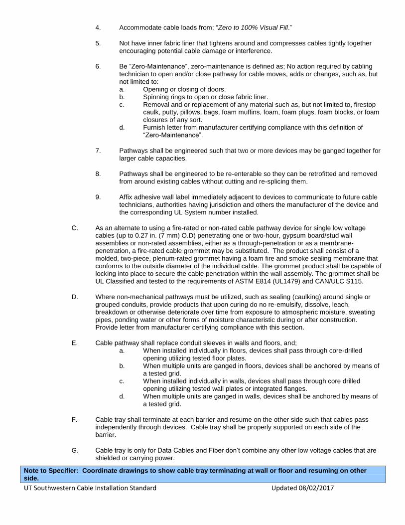
3. Have UL Systems permitting cable loads from; “Zero to 100% Visual Fill.” This requirement eliminates need for fill-ratio calculations to be made by cable technicians to ensure cable load is within maximum allowed by UL System.
4. Not have inner fabric liner that tightens around and compresses cables tightly together encouraging potential cable damage or interference.
5. Be “Zero-Maintenance”, zero-maintenance is defined as; No action required by cabling technician to open and/or close pathway for cable moves, adds or changes, such as, but not limited to: a. Opening or closing of doors. b. Spinning rings to open or close fabric liner. c. Removal and or replacement of any material such as, but not limited to, firestop
caulk, putty, pillows, bags, foam muffins, foam, foam plugs, foam blocks, or foam closures of any sort.
d. Furnish letter from manufacturer certifying compliance with this definition of “Zero-Maintenance”.
6. Pathways shall be engineered such that two or more devices may be ganged together for larger cable capacities.
7. Pathways shall be engineered to be re-enterable so they can be retrofitted and removed from around existing cables without cutting and re-splicing them.
8. Cable Pathway Devices passing vertically through floors shall have equal F & T Rating. (See UL System # F-A-3037, Item #4 “EZ-PATH Grid T-Rating Kit” Part # TRK444)
9. Affix adhesive wall label immediately adjacent to devices to communicate to future cable technicians, authorities having jurisdiction and others the manufacturer of the device and the corresponding UL System number installed.
B. Non rated cable pathway devices shall be used in non-fire-rated construction for ALL low-
voltage, video, data and voice cabling, optical fiber raceways and certain high-voltage cabling
where frequent cable moves, adds and changes may occur. Pathways required for high voltage
cabling will be detailed on the prints. Such devices shall:
1. Limit the movement of smoke and sound of wall and or floor penetrated.
2. Restore the STC Rating of the penetrated wall.
3. Provide L Ratings of <1 CFM when empty and <2.5 CFM at all other loading up to 100 percent.
UT Southwestern Cable Installation Standard Updated 08/02/2017
4. Accommodate cable loads from; “Zero to 100% Visual Fill.”
5. Not have inner fabric liner that tightens around and compresses cables tightly together encouraging potential cable damage or interference.
6. Be “Zero-Maintenance”, zero-maintenance is defined as; No action required by cabling technician to open and/or close pathway for cable moves, adds or changes, such as, but not limited to: a. Opening or closing of doors. b. Spinning rings to open or close fabric liner. c. Removal and or replacement of any material such as, but not limited to, firestop
caulk, putty, pillows, bags, foam muffins, foam, foam plugs, foam blocks, or foam closures of any sort.
d. Furnish letter from manufacturer certifying compliance with this definition of “Zero-Maintenance”.
7. Pathways shall be engineered such that two or more devices may be ganged together for larger cable capacities.
8. Pathways shall be engineered to be re-enterable so they can be retrofitted and removed from around existing cables without cutting and re-splicing them.
9. Affix adhesive wall label immediately adjacent to devices to communicate to future cable technicians, authorities having jurisdiction and others the manufacturer of the device and the corresponding UL System number installed.
C. As an alternate to using a fire-rated or non-rated cable pathway device for single low voltage cables (up to 0.27 in. (7 mm) O.D) penetrating one or two-hour, gypsum board/stud wall assemblies or non-rated assemblies, either as a through-penetration or as a membrane-penetration, a fire-rated cable grommet may be substituted. The product shall consist of a molded, two-piece, plenum-rated grommet having a foam fire and smoke sealing membrane that conforms to the outside diameter of the individual cable. The grommet product shall be capable of locking into place to secure the cable penetration within the wall assembly. The grommet shall be UL Classified and tested to the requirements of ASTM E814 (UL1479) and CAN/ULC S115.
D. Where non-mechanical pathways must be utilized, such as sealing (caulking) around single or grouped conduits, provide products that upon curing do no re-emulsify, dissolve, leach, breakdown or otherwise deteriorate over time from exposure to atmospheric moisture, sweating pipes, ponding water or other forms of moisture characteristic during or after construction. Provide letter from manufacturer certifying compliance with this section.
E. Cable pathway shall replace conduit sleeves in walls and floors, and; a. When installed individually in floors, devices shall pass through core-drilled
opening utilizing tested floor plates. b. When multiple units are ganged in floors, devices shall be anchored by means of
a tested grid. c. When installed individually in walls, devices shall pass through core drilled
opening utilizing tested wall plates or integrated flanges. d. When multiple units are ganged in walls, devices shall be anchored by means of
a tested grid.
F. Cable tray shall terminate at each barrier and resume on the other side such that cables pass independently through devices. Cable tray shall be properly supported on each side of the barrier.
G. Cable tray is only for Data Cables and Fiber don’t combine any other low voltage cables that are shielded or carrying power.
Note to Specifier: Coordinate drawings to show cable tray terminating at wall or floor and resuming on other side.

UT Southwestern Cable Installation Standard Updated 08/02/2017
1.5 SUBMITTALS
A. Submit under provisions of Section 01 30 00.
B. Product Data: Provide manufacturer’s standard catalog data for specified products demonstrating compliance with referenced standards and listing numbers of systems in which each product is to be used.
C. Schedule of UL System Drawings for Fire Rated Construction: Submit schedule of all expected opening locations and sizes, penetrating items, and required listed design numbers to seal openings to maintain fire resistance ratings.
D. UL System Drawings for Fire Rated Construction: Furnish copies of all UL Systems identified in schedule above. Include any engineering recommendations.
E. Certificates: Product Certificate of Compliance from the by manufacturer certifying material compliance with applicable code and specified performance characteristics.
F. Installation Instructions: Submit manufacturer’s printed installation instructions.
1.6 QUALITY ASSURANCE
A. Products/Systems: Provide firestopping systems that comply with the following requirements:
1. Firestopping tests are performed by a qualified, testing and inspection agency. A qualified testing and inspection agency is UL, or another agency performing testing and follow-up inspection services for firestop system acceptable to authorities having jurisdiction.
2. Firestopping products bear the classification marking of qualified testing and inspection agency.
B. Installer Qualifications: Experience in performing work of this section who is qualified by the firestopping manufacturer as having been provided the necessary training to install firestop products in accordance with specified requirements.
1.7 DELIVERY, STORAGE, AND HANDLING
A. Delivery:
1. Manufacturer’s original, unopened, undamaged containers, identification labels intact identifying product and manufacturer, date of manufacture; lot number; shelf life, if applicable; qualified testing and inspection agency’s classification marking; and mixing instruction for multi-component products.
2. Handle and store products according to manufacturer’s recommendations published in technical materials. Leave products wrapped or otherwise protected and under clean and dry storage conditions until required for installation.
B. Storage and Protection:
1. Store materials protected from exposure to harmful weather conditions and at temperature and humidity conditions recommended by manufacturer.
1.8 PROJECT CONDITIONS
A. Do not install products when ambient or substrate temperatures are outside limitations recommended by manufacturer.

UT Southwestern Cable Installation Standard Updated 08/02/2017
B. Do not install products when substrates are wet due to rain, frost, condensation, or other causes.
C. Maintain minimum temperature before, during, and for a minimum 3 days after installation of materials.
D. Do not use materials that contain flammable solvents.
E. Coordinate construction of openings and penetrating items to ensure that through-penetration firestop systems are installed according to specified requirements.
F. Coordinate sizing of sleeves, openings, core-drilled holes, or cut openings to accommodate through-penetration firestop systems.
G. Schedule installation of firestopping after completion of penetrating item installation but prior to covering or concealing of openings
PART 2 - PRODUCTS
2.1 MANUFACTURERS
A. Acceptable Manufacturer: Specified Technologies Inc., 200 Evans Way, Somerville, NJ 08876. Tel: (800) 992-1180, Fax: (908) 526-9623, Email: [email protected], Website: www.stifirestop.com.
B. Substitutions: Not permitted. No known equal.
C. Single Source: Obtain firestop systems for each type of penetration and construction condition indicated only from a single manufacturer.
2.2 MATERIALS
A. General: Use only products that have been tested for specific fire resistance rated construction conditions or acoustical and smoke related requirements conforming to construction assembly type, penetrating item type, annular space requirements, and rating involved for each separate instance.
B. Firestop Sealants: STI SpecSeal® Brand single component latex formulations that upon cure do not re-emulsify during exposure to moisture, the following products are acceptable:
1. Specified Technologies Inc. (STI) SpecSeal® Series SSS Sealant
2. Specified Technologies Inc. (STI) SpecSeal® Series LCI Sealant
C. Firestop Putty: STI SpecSeal® Brand intumescent, non-hardening, water resistant putties containing no solvents, inorganic fibers or silicone compounds, the following products are acceptable:
1. Specified Technologies Inc. (STI) SpecSeal® Series SSP Putty
D. Firestop Pillows: STI SpecSeal® Brand re-enterable, non-curing, mineral fiber core encapsulated on six sides with intumescent coating contained in a flame retardant poly bag, the following products are acceptable:
1. Specified Technologies Inc. (STI) SpecSeal® Series SSB Pillows
E. Fire-Rated Cable Grommet: STI SpecSeal® Brand Firestop Grommet is a molded, two-piece grommet with an integral fire and smoke sealing foam membrane for sealing individual cable penetrations through framed wall assemblies. Grommet snaps together around cable and locks tightly into the wall.

UT Southwestern Cable Installation Standard Updated 08/02/2017
1. Specified Technologies Inc. (STI) SpecSeal® Brand Ready® Firestop Grommets; RFG1
F. Fire-Rated Cable Pathways: STI EZ-PATH® Fire-Rated Pathway device modules comprised of steel pathway with self-adjusting intumescent foam pads allowing 0 to 100 percent cable fill, the following products are acceptable:
1. Specified Technologies Inc. (STI) EZ-PATH® Fire Rated Pathway
G. Smoke and Acoustical Pathways: STI EZ-PATH® Smoke & Acoustical Pathway device module
comprised of a nonmetallic pathway with integral self-adjusting smoke and sound sealing system for cable penetrations through non-fire-resistance rated wall or floor assemblies, the following products are acceptable:
1. Specified Technologies Inc. (STI) EZ-PATH® Smoke & Acoustical Pathway; Model No.
NEZ33
PART 3 - EXECUTION
3.1 EXAMINATION
A. Before beginning installation, verify that substrate conditions previously installed under other sections are acceptable for installation of firestopping in accordance with manufacturer’s installation instructions and technical information.
B. Surfaces shall be free of dirt, grease, oil, scale, laitance, rust, release agents, water repellants, and any other substances that may inhibit optimum adhesion.
C. Provide masking and temporary covering to protect adjacent surfaces.
D. Do not proceed until unsatisfactory conditions have been corrected.
3.2 INSTALLATION
A. General: Install systems in accordance with Performance Criteria and in accordance with the conditions of testing and classification as specified in the published design.
B. Manufacturer’s Instructions: Comply with manufacturer’s instructions for installation of products.
3.3 FIELD QUALITY CONTROL
A. Keep areas of work accessible until inspection by authorities having jurisdiction.
B. Where deficiencies are found, repair firestopping products so they comply with requirements.
3.4 ADJUSTING AND CLEANING
A. Remove equipment, materials, and debris, leaving area in undamaged, clean condition.
B. Clean all surfaces adjacent to sealed openings to be free of excess firestopping materials and soiling as work progresses.
3.5 SCHEDULES:
Review this list and update as required, Contact STI for assistance

UT Southwestern Cable Installation Standard Updated 08/02/2017
Penetrant Type Concrete Floor Concrete Wall Gypsum Board Wall
Blank Opening C-AJ-0100, C-AJ-
0101, C-AJ-0113, C-
AJ-0116
C-AJ-0100, C-AJ-
0101, C-AJ-0113, C-
AJ-0116
W-L-0020, W-L-0034
Metal Conduits C-AJ-1080, C-AJ-
1240, C-AJ-1353
C-AJ-1080, W-J-1098,
W-J-1100
W-L-1049, W-L-1222,
W-L-1168
Plastic
Conduits/
Raceways
C-AJ-2140, C-AJ-
2292, F-A-2186, F-A-
2210, F-A-2225
C-AJ-2038, C-AJ-
2108, C-AJ-2578, C-
AJ-2586, W-J-2018,
W-J-2076
W-L-2059, W-L-2074,
W-L-2093, W-L-2241
Cables C-AJ-3214, C-AJ-
3231, F-A-3015, F-A-
3021, F-A-3054
C-AJ-3214, C-AJ-
3231, W-J-3098, W-J-
3099,W-J-3124, W-J-
3150, W-J-3180
W-L-3219, W-L-3248,
W-L-3287, W-L-3356,
W-L-3377, W-L-3378,
W-L-3379, W-L-3390
Cable Trays C-AJ-3317, C-AJ-
8181, C-AJ-4029, F-
A-3015, F-A-3037
C-AJ-8181, W-J-4021,
W-J-4022, W-J-4033,
W-J-3098, W-J-3145,
W-J-3158
W-L-3218, W-L-3271,
W-L-3286, W-L-3306,
W-L-4008, W-L-4029,
W-L-4043, W-L-8073
Core Holes
All core holes must be STI Vertical Cable Solution and grouted to keep water from leaking between floors. All sleeves must extend 4” above the finished floor. Under no circumstance will any cable be installed in an un-sleeved
core hole. If any core holes are found to be un-sleeved, Infrastructure Services personnel must be notified. In the event that a contractor runs cable through an un-sleeved core hole, they will be required to re-install the cable at
their own expense. Under no circumstances are contractors allowed to drill core holes between floors or through
any structural support beams.
Horizontal Core Hole and Floor Pedestal Cables All core holes that will support horizontal cabling through walls must use appropriate sized STI firestoppping system.
All floor pedestals must be dual electric/communications and must be of a type that will readily accept Systimax jacks. All core holes in any TR or through any wall must be sleeved and fire stopped.
3.03 TR ENVIRONMENTAL CONTROLS
Electrical Each TR must have two standard convenience electrical outlets on opposite walls. There must also be one 20 amp
quad on a dedicated breaker outlet, and 2 NEMA L5-30’s located on ladder rack above the communications rack
that will service network hardware. If the facility has a backup generator, one (L5-30) in the TR will be wired from the generator panel.
Note: Electrical requirements for a MDF TR Room will be specified and outlined in the construction overview for each project.
HVAC Each TR must be provided with HVAC and a means to control the temperature in the TR.
Lighting
Each closet must be provided with adequate lighting to enable easy installation and maintenance of all components within the TR.
UT Southwestern Cable Installation Standard Updated 08/02/2017
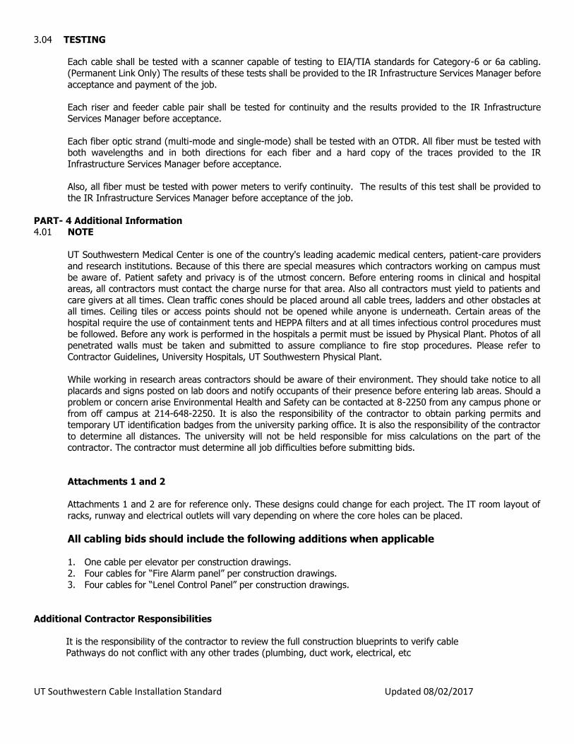
3.04 TESTING
Each cable shall be tested with a scanner capable of testing to EIA/TIA standards for Category-6 or 6a cabling.
(Permanent Link Only) The results of these tests shall be provided to the IR Infrastructure Services Manager before
acceptance and payment of the job.
Each riser and feeder cable pair shall be tested for continuity and the results provided to the IR Infrastructure Services Manager before acceptance.
Each fiber optic strand (multi-mode and single-mode) shall be tested with an OTDR. All fiber must be tested with both wavelengths and in both directions for each fiber and a hard copy of the traces provided to the IR
Infrastructure Services Manager before acceptance.
Also, all fiber must be tested with power meters to verify continuity. The results of this test shall be provided to the IR Infrastructure Services Manager before acceptance of the job.
PART- 4 Additional Information 4.01 NOTE
UT Southwestern Medical Center is one of the country's leading academic medical centers, patient-care providers
and research institutions. Because of this there are special measures which contractors working on campus must
be aware of. Patient safety and privacy is of the utmost concern. Before entering rooms in clinical and hospital areas, all contractors must contact the charge nurse for that area. Also all contractors must yield to patients and
care givers at all times. Clean traffic cones should be placed around all cable trees, ladders and other obstacles at all times. Ceiling tiles or access points should not be opened while anyone is underneath. Certain areas of the
hospital require the use of containment tents and HEPPA filters and at all times infectious control procedures must be followed. Before any work is performed in the hospitals a permit must be issued by Physical Plant. Photos of all
penetrated walls must be taken and submitted to assure compliance to fire stop procedures. Please refer to
Contractor Guidelines, University Hospitals, UT Southwestern Physical Plant.
While working in research areas contractors should be aware of their environment. They should take notice to all placards and signs posted on lab doors and notify occupants of their presence before entering lab areas. Should a
problem or concern arise Environmental Health and Safety can be contacted at 8-2250 from any campus phone or
from off campus at 214-648-2250. It is also the responsibility of the contractor to obtain parking permits and temporary UT identification badges from the university parking office. It is also the responsibility of the contractor
to determine all distances. The university will not be held responsible for miss calculations on the part of the contractor. The contractor must determine all job difficulties before submitting bids.
Attachments 1 and 2
Attachments 1 and 2 are for reference only. These designs could change for each project. The IT room layout of
racks, runway and electrical outlets will vary depending on where the core holes can be placed.
All cabling bids should include the following additions when applicable
1. One cable per elevator per construction drawings. 2. Four cables for “Fire Alarm panel” per construction drawings.
3. Four cables for “Lenel Control Panel” per construction drawings.
Additional Contractor Responsibilities
It is the responsibility of the contractor to review the full construction blueprints to verify cable Pathways do not conflict with any other trades (plumbing, duct work, electrical, etc

UT Southwestern Cable Installation Standard Updated 08/02/2017
ATTACHMENT 1
Fiber Distribution Switches Switches
Feeder/Riser Horizontal Horizontal
MODE
STACKSPEEDDUPLXSTATMASTRRPSSYST
Catalyst 3750 SERIES
1 2 3 4 5 6 7 8 9 10
1X
2X
15X
16X
11 12 13 14 15 16 17 18 19 20 21 22 23 24 25 26
17X
18X
31X
32X
27 28 29 30 31 32 33 34 35 36 37 38 39 40 41 42
33X
34X
47X
48X
43 44 45 46 47 48
2 4
1 3
MODE
STACKSPEEDDUPLXSTATMASTRRPSSYST
Catalyst 3750 SERIES
1 2 3 4 5 6 7 8 9 10
1X
2X
15X
16X
11 12 13 14 15 16 17 18 19 20 21 22 23 24 25 26
17X
18X
31X
32X
27 28 29 30 31 32 33 34 35 36 37 38 39 40 41 42
33X
34X
47X
48X
43 44 45 46 47 48
2 4
1 3
MODE
STACKSPEEDDUPLXSTATMASTRRPSSYST
Catalyst 3750 SERIES
1 2 3 4 5 6 7 8 9 10
1X
2X
15X
16X
11 12 13 14 15 16 17 18 19 20 21 22 23 24 25 26
17X
18X
31X
32X
27 28 29 30 31 32 33 34 35 36 37 38 39 40 41 42
33X
34X
47X
48X
43 44 45 46 47 48
2 4
1 3
MODE
STACKSPEEDDUPLXSTATMASTRRPSSYST
Catalyst 3750 SERIES
1 2 3 4 5 6 7 8 9 10
1X
2X
15X
16X
11 12 13 14 15 16 17 18 19 20 21 22 23 24 25 26
17X
18X
31X
32X
27 28 29 30 31 32 33 34 35 36 37 38 39 40 41 42
33X
34X
47X
48X
43 44 45 46 47 48
2 4
1 3
MODE
STACKSPEEDDUPLXSTATMASTRRPSSYST
Catalyst 3750 SERIES
1 2 3 4 5 6 7 8 9 10
1X
2X
15X
16X
11 12 13 14 15 16 17 18 19 20 21 22 23 24 25 26
17X
18X
31X
32X
27 28 29 30 31 32 33 34 35 36 37 38 39 40 41 42
33X
34X
47X
48X
43 44 45 46 47 48
2 4
1 3
MODE
STACKSPEEDDUPLXSTATMASTRRPSSYST
Catalyst 3750 SERIES
1 2 3 4 5 6 7 8 9 10
1X
2X
15X
16X
11 12 13 14 15 16 17 18 19 20 21 22 23 24 25 26
17X
18X
31X
32X
27 28 29 30 31 32 33 34 35 36 37 38 39 40 41 42
33X
34X
47X
48X
43 44 45 46 47 48
2 4
1 3
MODE
STACKSPEEDDUPLXSTATMASTRRPSSYST
Catalyst 3750 SERIES
1 2 3 4 5 6 7 8 9 10
1X
2X
15X
16X
11 12 13 14 15 16 17 18 19 20 21 22 23 24 25 26
17X
18X
31X
32X
27 28 29 30 31 32 33 34 35 36 37 38 39 40 41 42
33X
34X
47X
48X
43 44 45 46 47 48
2 4
1 3
MODE
STACKSPEEDDUPLXSTATMASTRRPSSYST
Catalyst 3750 SERIES
1 2 3 4 5 6 7 8 9 10
1X
2X
15X
16X
11 12 13 14 15 16 17 18 19 20 21 22 23 24 25 26
17X
18X
31X
32X
27 28 29 30 31 32 33 34 35 36 37 38 39 40 41 42
33X
34X
47X
48X
43 44 45 46 47 48
2 4
1 3
MODE
STACKSPEEDDUPLXSTATMASTRRPSSYST
Catalyst 3750 SERIES
1 2 3 4 5 6 7 8 9 10
1X
2X
15X
16X
11 12 13 14 15 16 17 18 19 20 21 22 23 24 25 26
17X
18X
31X
32X
27 28 29 30 31 32 33 34 35 36 37 38 39 40 41 42
33X
34X
47X
48X
43 44 45 46 47 48
2 4
1 3
MODE
STACKSPEEDDUPLXSTATMASTRRPSSYST
Catalyst 3750 SERIES
1 2 3 4 5 6 7 8 9 10
1X
2X
15X
16X
11 12 13 14 15 16 17 18 19 20 21 22 23 24 25 26
17X
18X
31X
32X
27 28 29 30 31 32 33 34 35 36 37 38 39 40 41 42
33X
34X
47X
48X
43 44 45 46 47 48
2 4
1 3
MODE
STACKSPEEDDUPLXSTATMASTRRPSSYST
Catalyst 3750 SERIES
1 2 3 4 5 6 7 8 9 10
1X
2X
15X
16X
11 12 13 14 15 16 17 18 19 20 21 22 23 24 25 26
17X
18X
31X
32X
27 28 29 30 31 32 33 34 35 36 37 38 39 40 41 42
33X
34X
47X
48X
43 44 45 46 47 48
2 4
1 3
MODE
STACKSPEEDDUPLXSTATMASTRRPSSYST
Catalyst 3750 SERIES
1 2 3 4 5 6 7 8 9 10
1X
2X
15X
16X
11 12 13 14 15 16 17 18 19 20 21 22 23 24 25 26
17X
18X
31X
32X
27 28 29 30 31 32 33 34 35 36 37 38 39 40 41 42
33X
34X
47X
48X
43 44 45 46 47 48
2 4
1 3
MODE
STACKSPEEDDUPLXSTATMASTRRPSSYST
Catalyst 3750 SERIES
1 2 3 4 5 6 7 8 9 10
1X
2X
15X
16X
11 12 13 14 15 16 17 18 19 20 21 22 23 24 25 26
17X
18X
31X
32X
27 28 29 30 31 32 33 34 35 36 37 38 39 40 41 42
33X
34X
47X
48X
43 44 45 46 47 48
2 4
1 3
MODE
STACKSPEEDDUPLXSTATMASTRRPSSYST
Catalyst 3750 SERIES
1 2 3 4 5 6 7 8 9 10
1X
2X
15X
16X
11 12 13 14 15 16 17 18 19 20 21 22 23 24 25 26
17X
18X
31X
32X
27 28 29 30 31 32 33 34 35 36 37 38 39 40 41 42
33X
34X
47X
48X
43 44 45 46 47 48
2 4
1 3

UT Southwestern Cable Installation Standard Updated 08/02/2017
ATTACHMENT 2
4- - 4” STI EZPath Vertical Paths
Quad, dedicated 120vac outlet 20
amp breaker and 2 NEMA-L5-30’s
2-19” relay racks and 3 vertical wire
managers Gray represents plywood
installed floor to ceiling Painted
White don’t paint over the Fire
rated Stamps
Courtesy electrical outlet
Ground Bar
Cable entry into TR using 44 series STI
EzPath system.

UT Southwestern Cable Installation Standard Updated 08/02/2017
ATTACHMENT 3
Partial Rack Configuration
MODE
STACKSPEEDDUPLXSTATMASTRRPSSYST
Catalyst 3750 SERIES
1 2 3 4 5 6 7 8 9 10
1X
2X
15X
16X
11 12 13 14 15 16 17 18 19 20 21 22 23 24 25 26
17X
18X
31X
32X
27 28 29 30 31 32 33 34 35 36 37 38 39 40 41 42
33X
34X
47X
48X
43 44 45 46 47 48
2 4
1 3
MODE
STACKSPEEDDUPLXSTATMASTRRPSSYST
Catalyst 3750 SERIES
1 2 3 4 5 6 7 8 9 10
1X
2X
15X
16X
11 12 13 14 15 16 17 18 19 20 21 22 23 24 25 26
17X
18X
31X
32X
27 28 29 30 31 32 33 34 35 36 37 38 39 40 41 42
33X
34X
47X
48X
43 44 45 46 47 48
2 4
1 3
MODE
STACKSPEEDDUPLXSTATMASTRRPSSYST
Catalyst 3750 SERIES
1 2 3 4 5 6 7 8 9 10
1X
2X
15X
16X
11 12 13 14 15 16 17 18 19 20 21 22 23 24 25 26
17X
18X
31X
32X
27 28 29 30 31 32 33 34 35 36 37 38 39 40 41 42
33X
34X
47X
48X
43 44 45 46 47 48
2 4
1 3
MODE
STACKSPEEDDUPLXSTATMASTRRPSSYST
Catalyst 3750 SERIES
1 2 3 4 5 6 7 8 9 10
1X
2X
15X
16X
11 12 13 14 15 16 17 18 19 20 21 22 23 24 25 26
17X
18X
31X
32X
27 28 29 30 31 32 33 34 35 36 37 38 39 40 41 42
33X
34X
47X
48X
43 44 45 46 47 48
2 4
1 3
MODE
STACKSPEEDDUPLXSTATMASTRRPSSYST
Catalyst 3750 SERIES
1 2 3 4 5 6 7 8 9 10
1X
2X
15X
16X
11 12 13 14 15 16 17 18 19 20 21 22 23 24 25 26
17X
18X
31X
32X
27 28 29 30 31 32 33 34 35 36 37 38 39 40 41 42
33X
34X
47X
48X
43 44 45 46 47 48
2 4
1 3
MODE
STACKSPEEDDUPLXSTATMASTRRPSSYST
Catalyst 3750 SERIES
1 2 3 4 5 6 7 8 9 10
1X
2X
15X
16X
11 12 13 14 15 16 17 18 19 20 21 22 23 24 25 26
17X
18X
31X
32X
27 28 29 30 31 32 33 34 35 36 37 38 39 40 41 42
33X
34X
47X
48X
43 44 45 46 47 48
2 4
1 3
MODE
STACKSPEEDDUPLXSTATMASTRRPSSYST
Catalyst 3750 SERIES
1 2 3 4 5 6 7 8 9 10
1X
2X
15X
16X
11 12 13 14 15 16 17 18 19 20 21 22 23 24 25 26
17X
18X
31X
32X
27 28 29 30 31 32 33 34 35 36 37 38 39 40 41 42
33X
34X
47X
48X
43 44 45 46 47 48
2 4
1 3
MODE
STACKSPEEDDUPLXSTATMASTRRPSSYST
Catalyst 3750 SERIES
1 2 3 4 5 6 7 8 9 10
1X
2X
15X
16X
11 12 13 14 15 16 17 18 19 20 21 22 23 24 25 26
17X
18X
31X
32X
27 28 29 30 31 32 33 34 35 36 37 38 39 40 41 42
33X
34X
47X
48X
43 44 45 46 47 48
2 4
1 3
1 U