Usingcomputationalfluiddynamicsincombatingerosion–corrosion · Neši´c and Postlethwaite (1990)...
12
Chemical Engineering Science 61 (2006) 4086 – 4097 www.elsevier.com/locate/ces Using computational fluid dynamics in combating erosion–corrosion Srdjan Neši´ c ∗ The Department of Mechanical Engineering, University of Queensland, Brisbane, Qld 4000, Australia Received 14 January 2005; received in revised form 29 December 2005; accepted 30 January 2006 Available online 22 March 2006 Abstract Computational fluid dynamics was used to search for the links between the observed pattern of attack seen in a bauxite refinery’s heat exchanger headers and the hydrodynamics inside the header. Validation of the computational fluid dynamics results was done by comparing then with flow parameters measured in a 1:5 scale model of the first pass header in the laboratory. Computational fluid dynamics simulations were used to establish hydrodynamic similarity between the 1:5 scale and full scale models of the first pass header. It was found that the erosion–corrosion damage seen at the tubesheet of the first pass header was a consequence of increased levels of turbulence at the tubesheet caused by a rapidly turning flow. A prismatic flow corrections device introduced in the past helped in rectifying the problem at the tubesheet but exaggerated the erosion–corrosion problem at the first pass header shell. A number of alternative flow correction devices were tested using computational fluid dynamics. Axial ribbing in the first pass header and an inlet flow diffuser have shown the best performance and were recommended for implementation. Computational fluid dynamics simulations have revealed a smooth orderly low turbulence flow pattern in the second, third and fourth pass as well as the exit headers where no erosion–corrosion was seen in practice. This study has confirmed that near-wall turbulence intensity, which can be successfully predicted by using computational fluid dynamics, is a good hydrodynamic predictor of erosion–corrosion damage in complex geometries. 2006 Published by Elsevier Ltd. Keywords: Computational fluid dynamics; Erosion–corrosion 1. Introduction Bauxite refineries frequently utilize what is known as the “Bayer process” in the production of aluminium oxide (alu- mina) from bauxite ore (King, 1987). Bauxite can typically be found close to the surface of the earth in seams varying from 1 to 10 m in the form of small reddish pebbles. Alumina (alu- minium oxide Al 2 O 3 ) is a granular white material which is further processed to obtain aluminium. The Bayer process was discovered by an Austrian chemist Karl Josef Bayer in 1887 and involves (a) dissolving aluminium component of the baux- ite ore in a sodium hydroxide solution (caustic soda); (b) re- moving impurities from the solution; (c) precipitating alumina ∗ Chemical Engineering, Institute for Corrosion and Multiphase Technol- ogy, 342 West State Street, Athens, OH 45701, USA. Tel.: +1 740 593 9945; fax: +1 740 593 9949. E-mail address: [email protected]. 0009-2509/$ - see front matter 2006 Published by Elsevier Ltd. doi:10.1016/j.ces.2006.01.052 trihydrate; (d) calcination to aluminium oxide. Large quantities of caustic soda solution are recycled through a bauxite refinery and the bauxite ore is added at a high temperature, impurities are separated at an intermediate temperature, and alumina is precipitated at the low temperature point in the cycle. As a part of the Bayer process, the caustic solution is passed through shell-and-tube heat exchangers (HEX) in or- der to regenerate heat. Regularly the HEX are cleaned and de-scaled by using inhibited mineral acid. The headers of these HEX, which are constructed of mild steel, are regu- larly inspected for erosion–corrosion damage. Online, this is typically done by using ultrasonic measurements of shell thickness. Occasionally they are taken off-line, opened, in- spected visually for damage and if needed repaired. Long term data collection has indicated localized damage to certain sections of the HEX tube sheet and header shells. Based on the pattern of damage it was suspected that this damage could be related to the flow pattern of the fluid within the HEX header.
Transcript of Usingcomputationalfluiddynamicsincombatingerosion–corrosion · Neši´c and Postlethwaite (1990)...
Chemical Engineering Science 61 (2006) 4086–4097www.elsevier.com/locate/ces
Using computational fluid dynamics in combating erosion–corrosion
Srdjan Nešic∗
The Department of Mechanical Engineering, University of Queensland, Brisbane, Qld 4000, Australia
Received 14 January 2005; received in revised form 29 December 2005; accepted 30 January 2006Available online 22 March 2006
Abstract
Computational fluid dynamics was used to search for the links between the observed pattern of attack seen in a bauxite refinery’s heatexchanger headers and the hydrodynamics inside the header. Validation of the computational fluid dynamics results was done by comparingthen with flow parameters measured in a 1:5 scale model of the first pass header in the laboratory. Computational fluid dynamics simulationswere used to establish hydrodynamic similarity between the 1:5 scale and full scale models of the first pass header. It was found that theerosion–corrosion damage seen at the tubesheet of the first pass header was a consequence of increased levels of turbulence at the tubesheetcaused by a rapidly turning flow. A prismatic flow corrections device introduced in the past helped in rectifying the problem at the tubesheetbut exaggerated the erosion–corrosion problem at the first pass header shell. A number of alternative flow correction devices were tested usingcomputational fluid dynamics. Axial ribbing in the first pass header and an inlet flow diffuser have shown the best performance and wererecommended for implementation. Computational fluid dynamics simulations have revealed a smooth orderly low turbulence flow pattern inthe second, third and fourth pass as well as the exit headers where no erosion–corrosion was seen in practice. This study has confirmed thatnear-wall turbulence intensity, which can be successfully predicted by using computational fluid dynamics, is a good hydrodynamic predictorof erosion–corrosion damage in complex geometries.� 2006 Published by Elsevier Ltd.
Keywords: Computational fluid dynamics; Erosion–corrosion
1. Introduction
Bauxite refineries frequently utilize what is known as the“Bayer process” in the production of aluminium oxide (alu-mina) from bauxite ore (King, 1987). Bauxite can typically befound close to the surface of the earth in seams varying from1 to 10 m in the form of small reddish pebbles. Alumina (alu-minium oxide Al2O3) is a granular white material which isfurther processed to obtain aluminium. The Bayer process wasdiscovered by an Austrian chemist Karl Josef Bayer in 1887and involves (a) dissolving aluminium component of the baux-ite ore in a sodium hydroxide solution (caustic soda); (b) re-moving impurities from the solution; (c) precipitating alumina
∗ Chemical Engineering, Institute for Corrosion and Multiphase Technol-ogy, 342 West State Street, Athens, OH 45701, USA. Tel.: +1 740 593 9945;fax: +1 740 593 9949.
E-mail address: [email protected].
0009-2509/$ - see front matter � 2006 Published by Elsevier Ltd.doi:10.1016/j.ces.2006.01.052
trihydrate; (d) calcination to aluminium oxide. Large quantitiesof caustic soda solution are recycled through a bauxite refineryand the bauxite ore is added at a high temperature, impuritiesare separated at an intermediate temperature, and alumina isprecipitated at the low temperature point in the cycle.
As a part of the Bayer process, the caustic solution ispassed through shell-and-tube heat exchangers (HEX) in or-der to regenerate heat. Regularly the HEX are cleaned andde-scaled by using inhibited mineral acid. The headers ofthese HEX, which are constructed of mild steel, are regu-larly inspected for erosion–corrosion damage. Online, thisis typically done by using ultrasonic measurements of shellthickness. Occasionally they are taken off-line, opened, in-spected visually for damage and if needed repaired. Longterm data collection has indicated localized damage to certainsections of the HEX tube sheet and header shells. Based onthe pattern of damage it was suspected that this damage couldbe related to the flow pattern of the fluid within the HEXheader.
S. Nešic / Chemical Engineering Science 61 (2006) 4086–4097 4087
Erosion–corrosion is defined as a process in which there isan accelerated loss of metal due to the relative movement of acorrosive fluid over a metal surface (Fontana, 1986). In mostcases the protective surface layer on the metal is either erodedor the formation of the layer is altered as a result of flow. Inthe case of HEX headers, it is speculated that the protectivelayer formed on the mild steel surfaces in caustic solutions isremoved or never forms properly due to fluid flow, which thenin turn facilitates base metal loss by the corrosive action. Asthere was no evidence of solid particles present in the liquidany effect of hydrodynamics on corrosion would have occurredin single phase flow.
To confirm this hypothesis it was decided to use computa-tional fluid dynamics (CFD) to search for the link(s) betweenthe observed pattern of attack seen in practice and the hy-drodynamics in the HEX header. CFD nowadays provides anoption to look into fluid flow, which is often cheaper then ex-perimentation, can provide detailed results and is suitable foralmost any complex geometry. However, computational solu-tions are based on mathematical models which approximatereality with varying degrees of accuracy. Therefore, solutionsobtained by computations need to be validated with experi-ments whenever possible and interpreted carefully. The fact thatlarge volumes of plausible hydrodynamic results can be rapidlygenerated with commercial CFD packages can lead to super-ficiality where meaningful content is obscured by the colour-ful presentations of the results and good looking imagery. Thisdoes not take away from the great potential that CFD has inhelping engineers to cope with complex fluid dynamics prob-lems, it just points to a frequent aberration/abuse of the CFDtechnique.
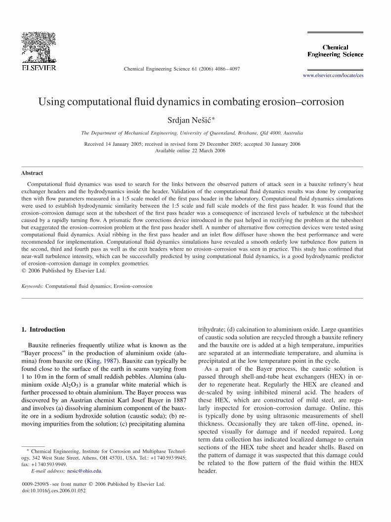
To gain confidence in the validity of the CFD results, smallscale hydrodynamic experiments were conducted at the be-ginning of this project on a one-fifth scale (1:5) laboratorymodel of the HEX. For the picture of the 1:5 scale model seeFig. 1. Once confidence in CFD results was established by sim-ulating the flow in the 1:5 scale model, scaling up the hydrody-namic simulation from the model to full scale was a relativelysimple and cheap exercise by using CFD, something that wouldbe very costly if not impossible to do empirically. CFD was alsoused to investigate geometrical modifications that would alterthe flow pattern and alleviate the erosion–corrosion problem.
Fig. 1. The 1:5 scale model of the shell-and-tube HEX tested in the laboratory.
2. Experimental background
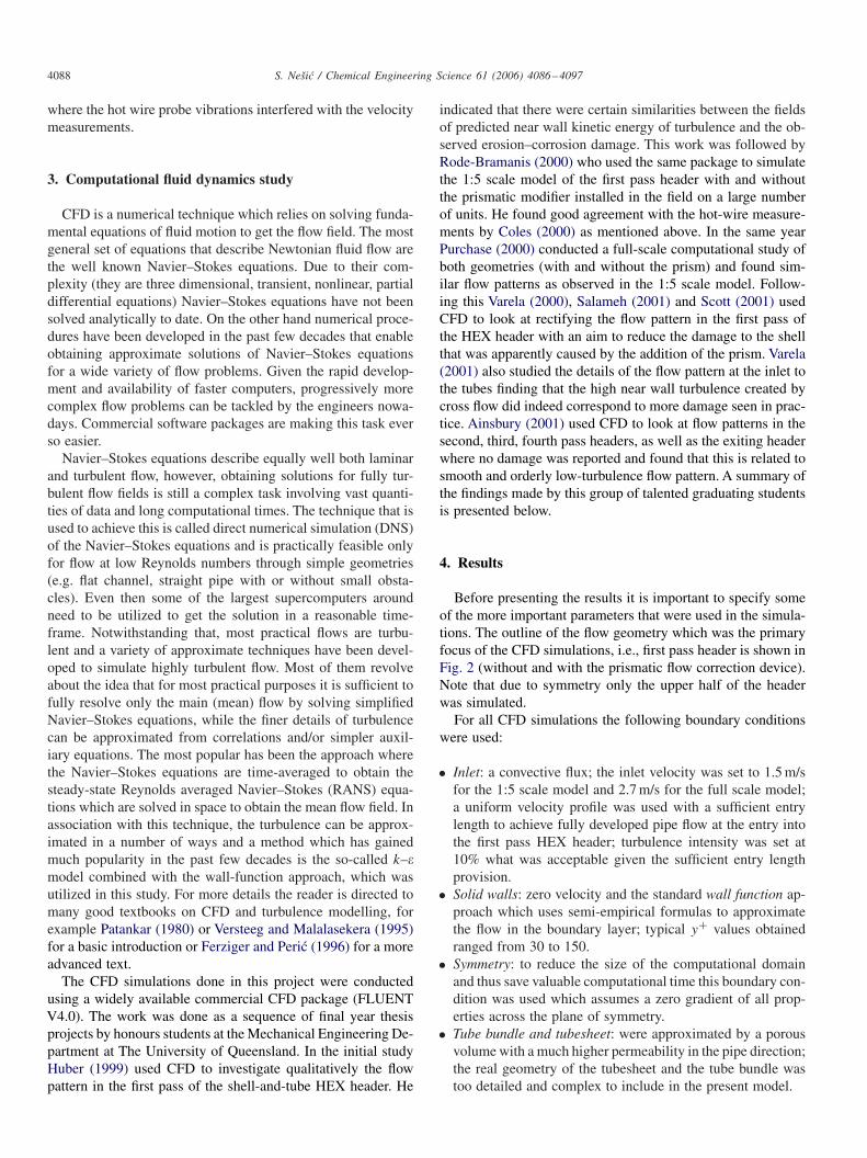
Lai (1977), Bremhorst and Lai (1979), Lai and Bremhorst(1979), Bremhorst and Flint (1991), empirically examined theflow patterns inside the one-fifth scale model HEX header, thesame one as shown in Fig. 1. The main concern at the timewas the erosion–corrosion damage occurring at the tube inlets(tubesheet). Consequently, the main hydrodynamic parameterstudied was velocity distribution near the tube inlets. Bremhorstand co-workers determined that the cross flow pattern (parallelto the tube sheet) was the main reason for the erosion–corrosionof the tube inlets. Their experiments tested various flow correc-tion devices that would alter the flow pattern so that the bulkof the flow would approach the tube inlets axially. It was fromthis study that the prismatic flow correction devices were rec-ommended and then installed at the plant. Long term use hasproven to have been beneficial and on-balance less damage tothe tube inlets has been seen. However, it was suspected thatthe changed flow pattern may have caused an increase in thedamage rate to the shell.
The exact mechanism of erosion–corrosion by which theprotective oxide layer is initially removed or its formation in-hibited is not yet well understood. Studies conducted in recentyears have suggested some possible mechanisms. A relevantstudy concerning tube inlet damage was published by Elvery(1995) and Elvery and Bremhorst (1997). The main hydrody-namic parameters under consideration were the wall pressureand wall shear stresses present in the tube inlets for varyinginlet inclined flow conditions. The results obtained comparedwell with observed damage in tube inlets and pointed to the im-portance of the areas near the reattachment point of the recircu-lation region formed by the inclined flow. The mean wall shearstresses were thought to be too small to mechanically removethe metal’s protective layer. This led them to believe that meanwall shear stresses alone were not responsible for removal ofthe oxide layers, and suggested that another mechanism had tobe responsible.
Nešic and Postlethwaite (1990) suggested that near wallturbulent kinetic energy was responsible for the mechanicalprotective film removal and enhanced mass transfer rates incorrosion of metals. The study carried out for single-phaseflows showed that localized, near wall turbulent kinetic en-ergy was responsible for enhanced mass transfer rates. Nešicand Postlethwaite (1990) believed that the intensive near wallturbulence disrupts both the protective oxide layer of thebase metal and also the mass transfer boundary layer, whichleads to the enhanced corrosion and subsequent failure ofmetals. Consequently, the studies in the present project fo-cussed on the near wall turbulent kinetic energy, as it wasbelieved that this was one of the most likely factors that couldcontribute significantly to the observed erosion–corrosiondamage.
A recent experimental study was conducted by Coles(2000) as a part of the present project. The purpose of thisexperimental study was to validate the CFD results for theone-fifth scale model. The experimental results found goodagreement with the numerical model, except for some instances
4088 S. Nešic / Chemical Engineering Science 61 (2006) 4086–4097
where the hot wire probe vibrations interfered with the velocitymeasurements.
3. Computational fluid dynamics study
CFD is a numerical technique which relies on solving funda-mental equations of fluid motion to get the flow field. The mostgeneral set of equations that describe Newtonian fluid flow arethe well known Navier–Stokes equations. Due to their com-plexity (they are three dimensional, transient, nonlinear, partialdifferential equations) Navier–Stokes equations have not beensolved analytically to date. On the other hand numerical proce-dures have been developed in the past few decades that enableobtaining approximate solutions of Navier–Stokes equationsfor a wide variety of flow problems. Given the rapid develop-ment and availability of faster computers, progressively morecomplex flow problems can be tackled by the engineers nowa-days. Commercial software packages are making this task everso easier.
Navier–Stokes equations describe equally well both laminarand turbulent flow, however, obtaining solutions for fully tur-bulent flow fields is still a complex task involving vast quanti-ties of data and long computational times. The technique that isused to achieve this is called direct numerical simulation (DNS)of the Navier–Stokes equations and is practically feasible onlyfor flow at low Reynolds numbers through simple geometries(e.g. flat channel, straight pipe with or without small obsta-cles). Even then some of the largest supercomputers aroundneed to be utilized to get the solution in a reasonable time-frame. Notwithstanding that, most practical flows are turbu-lent and a variety of approximate techniques have been devel-oped to simulate highly turbulent flow. Most of them revolveabout the idea that for most practical purposes it is sufficient tofully resolve only the main (mean) flow by solving simplifiedNavier–Stokes equations, while the finer details of turbulencecan be approximated from correlations and/or simpler auxil-iary equations. The most popular has been the approach wherethe Navier–Stokes equations are time-averaged to obtain thesteady-state Reynolds averaged Navier–Stokes (RANS) equa-tions which are solved in space to obtain the mean flow field. Inassociation with this technique, the turbulence can be approx-imated in a number of ways and a method which has gainedmuch popularity in the past few decades is the so-called k–�model combined with the wall-function approach, which wasutilized in this study. For more details the reader is directed tomany good textbooks on CFD and turbulence modelling, forexample Patankar (1980) or Versteeg and Malalasekera (1995)for a basic introduction or Ferziger and Peric (1996) for a moreadvanced text.
The CFD simulations done in this project were conductedusing a widely available commercial CFD package (FLUENTV4.0). The work was done as a sequence of final year thesisprojects by honours students at the Mechanical Engineering De-partment at The University of Queensland. In the initial studyHuber (1999) used CFD to investigate qualitatively the flowpattern in the first pass of the shell-and-tube HEX header. He
indicated that there were certain similarities between the fieldsof predicted near wall kinetic energy of turbulence and the ob-served erosion–corrosion damage. This work was followed byRode-Bramanis (2000) who used the same package to simulatethe 1:5 scale model of the first pass header with and withoutthe prismatic modifier installed in the field on a large numberof units. He found good agreement with the hot-wire measure-ments by Coles (2000) as mentioned above. In the same yearPurchase (2000) conducted a full-scale computational study ofboth geometries (with and without the prism) and found sim-ilar flow patterns as observed in the 1:5 scale model. Follow-ing this Varela (2000), Salameh (2001) and Scott (2001) usedCFD to look at rectifying the flow pattern in the first pass ofthe HEX header with an aim to reduce the damage to the shellthat was apparently caused by the addition of the prism. Varela(2001) also studied the details of the flow pattern at the inlet tothe tubes finding that the high near wall turbulence created bycross flow did indeed correspond to more damage seen in prac-tice. Ainsbury (2001) used CFD to look at flow patterns in thesecond, third, fourth pass headers, as well as the exiting headerwhere no damage was reported and found that this is related tosmooth and orderly low-turbulence flow pattern. A summary ofthe findings made by this group of talented graduating studentsis presented below.
4. Results
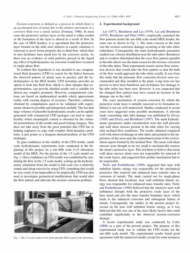
Before presenting the results it is important to specify someof the more important parameters that were used in the simula-tions. The outline of the flow geometry which was the primaryfocus of the CFD simulations, i.e., first pass header is shown inFig. 2 (without and with the prismatic flow correction device).Note that due to symmetry only the upper half of the headerwas simulated.
For all CFD simulations the following boundary conditionswere used:
• Inlet: a convective flux; the inlet velocity was set to 1.5 m/sfor the 1:5 scale model and 2.7 m/s for the full scale model;a uniform velocity profile was used with a sufficient entrylength to achieve fully developed pipe flow at the entry intothe first pass HEX header; turbulence intensity was set at10% what was acceptable given the sufficient entry lengthprovision.
• Solid walls: zero velocity and the standard wall function ap-proach which uses semi-empirical formulas to approximatethe flow in the boundary layer; typical y+ values obtainedranged from 30 to 150.
• Symmetry: to reduce the size of the computational domainand thus save valuable computational time this boundary con-dition was used which assumes a zero gradient of all prop-erties across the plane of symmetry.
• Tube bundle and tubesheet: were approximated by a porousvolume with a much higher permeability in the pipe direction;the real geometry of the tubesheet and the tube bundle wastoo detailed and complex to include in the present model.
S. Nešic / Chemical Engineering Science 61 (2006) 4086–4097 4089
Fig. 2. The side view outline of the upper half of the first pass HEX header simulated by using CFD; (a) without and (b) with prismatic flow correction device.
A second order accurate numerical scheme was used. Theconvergence criteria needed to be set, which signal when theapproximate solution is judged to be sufficiently accurate. Forthe majority of the runs, the only convergence criteria usedwere the unscaled residuals of all points in the domain whichwere required to drop by five orders of magnitude during thesimulation, relative to the initial value. Grid independenceof the solution was established by repeating the simulationson a sequence of ever so finer non-uniform structured com-putational grids (thereby increasing the spatial resolution ofthe calculated answer) until sufficient accuracy was achieved.A final answer was judged to be sufficiently accurate if thechanges in the key control parameters from one grid to the nextfiner one was less than 1%. The total number of tetrahedralcontrol values for a typical simulation varied from 200,000to 1,500,000.
4.1. Comparison of 1:5 and full scale results for the first passheader
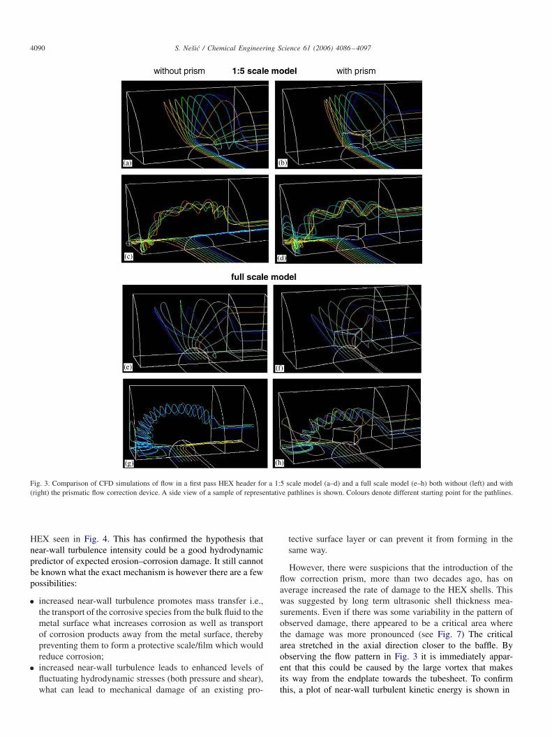
After successfully verifying the CFD simulations for a 1:5scale model by comparing with the hot-film measurements donein the lab (Coles, 2000; Rode-Bramanis, 2000), it was importantto establish hydrodynamic similarity between the 1:5 scale andfull scale models. The same inlet pipe Reynolds number wasused as the similarity criterion. Simulations were performed forthe both flow geometries and indeed it took much longer to getthe answer for the full scale model where a 100 times morecomputational nodes were used. It was gratifying to find outthat the flow patterns obtained in the two scale models was verysimilar as indicated in Fig. 3 where characteristic pathlines areshown. Many more qualitative hydrodynamic parameters wereobtained and compared for the two geometries with the samesuccess; however their presentation exceeds the scope of thispaper (see for example Purchase, 2000).
It can be seen on all the plots in Fig. 3 that upon enter-ing the first pass header the fluid goes into a large swirl thatapproaches the tubesheet at a high angle of incidence onlyto rapidly turn there and enter the tubes. A portion of theinflow initially turns away from the tubesheet and moves to-wards the front plate, turns around there and spirals rapidly
towards the tubesheet. These simulations confirmed the exper-imental findings of Bremhorst and co-workers (1977–1991)who indicated significant “cross flow” at the tube sheet. FromFig. 3 it appears that the prismatic flow correction devicethat was suggested as a remedy by Bremhorst and co-workers(1977–1991) did not achieve much in terms of rectifying theflow pattern, a fact not completely born out by a subsequentmore in-depth analysis of the key flow parameters as discussedbelow.
4.2. Flow pattern vs. erosion–corrosion damage for the firstpass header
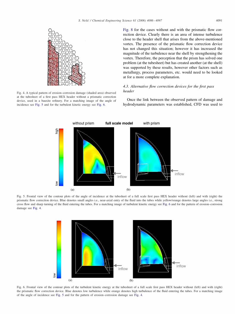
In long term (a decade long) observations on the real HEX,a consistent pattern of damage was observed at the tubesheet.The inlets to certain groups of tubes were affected more thanothers and a typical damage pattern for the tubesheet in thefull scale first pass header of a shell-and-tube HEX is shownin Fig. 4. This particular damage pattern is what signalled thatthe attack might be flow related and prompted Bremhorst andco-workers (1977–1991) to study the flow pattern and proposethe prism as a flow correction device. The CFD simulationsdone for a full scale first pass HEX header without and withthe prismatic flow correction device have revealed that the in-troduction of the prism did change the angle of incidence of thefluid as it approached the tubesheet (see Fig. 5) as Bremhorstand co-workers (1977–1991) has claimed. Even if this is notobvious in the qualitative plots of the pathlines shown inFig. 3, upon closer inspection of the data it was found thatthe prism deflected more of the incoming fluid away from thetubesheet and toward the endplate what gave it a longer pathand a better chance to align the approach to the tubesheet. As aconsequence less twisting and turning of the fluid occurred atthe tubesheet resulting in lower degree of turbulence as shownin Fig. 6. Note that the same scale for the kinetic energy ofturbulence was used in all the plots in this paper so that theycan be qualitatively compared (low value being 0 and the highvalue being 0.134 m2/s2). Given the variability of the damagepattern from one to another HEX, there is rather good matchof the predicted level of near-wall turbulence intensity shownin Fig. 6a and the observed pattern of damage for one of the
4090 S. Nešic / Chemical Engineering Science 61 (2006) 4086–4097
Fig. 3. Comparison of CFD simulations of flow in a first pass HEX header for a 1:5 scale model (a–d) and a full scale model (e–h) both without (left) and with(right) the prismatic flow correction device. A side view of a sample of representative pathlines is shown. Colours denote different starting point for the pathlines.
HEX seen in Fig. 4. This has confirmed the hypothesis thatnear-wall turbulence intensity could be a good hydrodynamicpredictor of expected erosion–corrosion damage. It still cannotbe known what the exact mechanism is however there are a fewpossibilities:
• increased near-wall turbulence promotes mass transfer i.e.,the transport of the corrosive species from the bulk fluid to themetal surface what increases corrosion as well as transportof corrosion products away from the metal surface, therebypreventing them to form a protective scale/film which wouldreduce corrosion;
• increased near-wall turbulence leads to enhanced levels offluctuating hydrodynamic stresses (both pressure and shear),what can lead to mechanical damage of an existing pro-
tective surface layer or can prevent it from forming in thesame way.
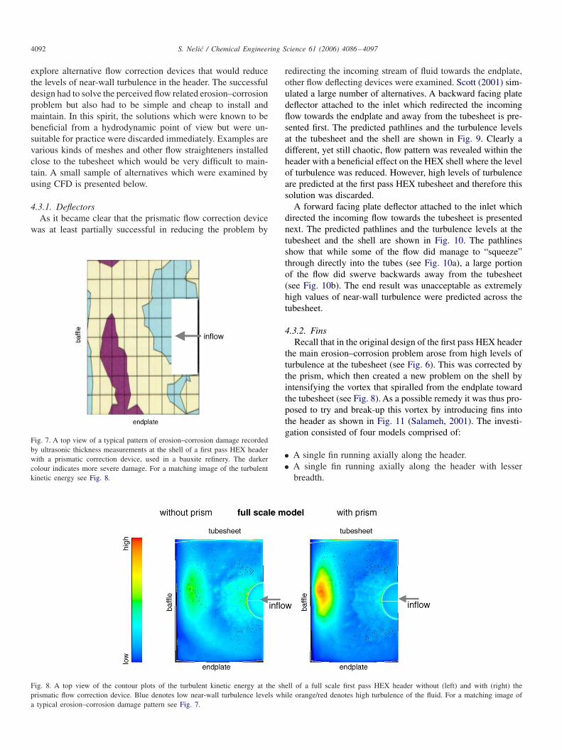
However, there were suspicions that the introduction of theflow correction prism, more than two decades ago, has onaverage increased the rate of damage to the HEX shells. Thiswas suggested by long term ultrasonic shell thickness mea-surements. Even if there was some variability in the pattern ofobserved damage, there appeared to be a critical area wherethe damage was more pronounced (see Fig. 7) The criticalarea stretched in the axial direction closer to the baffle. Byobserving the flow pattern in Fig. 3 it is immediately appar-ent that this could be caused by the large vortex that makesits way from the endplate towards the tubesheet. To confirmthis, a plot of near-wall turbulent kinetic energy is shown in
S. Nešic / Chemical Engineering Science 61 (2006) 4086–4097 4091
Fig. 4. A typical pattern of erosion–corrosion damage (shaded area) observedat the tubesheet of a first pass HEX header without a prismatic correctiondevice, used in a bauxite refinery. For a matching image of the angle ofincidence see Fig. 5 and for the turbulent kinetic energy see Fig. 6.
Fig. 5. Frontal view of the contour plots of the angle of incidence at the tubesheet of a full scale first pass HEX header without (left) and with (right) theprismatic flow correction device. Blue denotes small angles i.e., near-axial entry of the fluid into the tubes while yellow/orange denotes large angles i.e., strongcross flow and sharp turning of the fluid entering the tubes. For a matching image of turbulent kinetic energy see Fig. 6 and for the pattern of erosion–corrosiondamage see Fig. 4.
Fig. 6. Frontal view of the contour plots of the turbulent kinetic energy at the tubesheet of a full scale first pass HEX header without (left) and with (right)the prismatic flow correction device. Blue denotes low turbulence while orange denotes high turbulence of the fluid entering the tubes. For a matching imageof the angle of incidence see Fig. 5 and for the pattern of erosion–corrosion damage see Fig. 4.
Fig. 8 for the cases without and with the prismatic flow cor-rection device. Clearly there is an area of intense turbulenceclose to the header shell that arises from the above-mentionedvortex. The presence of the prismatic flow correction devicehas not changed this situation; however it has increased themagnitude of the turbulence near the shell by strengthening thevortex. Therefore, the perception that the prism has solved oneproblem (at the tubesheet) but has created another (at the shell)was supported by these results, however other factors such asmetallurgy, process parameters, etc. would need to be lookedat for a more complete explanation.
4.3. Alternative flow correction devices for the first passheader
Once the link between the observed pattern of damage andhydrodynamic parameters was established, CFD was used to
4092 S. Nešic / Chemical Engineering Science 61 (2006) 4086–4097
explore alternative flow correction devices that would reducethe levels of near-wall turbulence in the header. The successfuldesign had to solve the perceived flow related erosion–corrosionproblem but also had to be simple and cheap to install andmaintain. In this spirit, the solutions which were known to bebeneficial from a hydrodynamic point of view but were un-suitable for practice were discarded immediately. Examples arevarious kinds of meshes and other flow straighteners installedclose to the tubesheet which would be very difficult to main-tain. A small sample of alternatives which were examined byusing CFD is presented below.
4.3.1. DeflectorsAs it became clear that the prismatic flow correction device
was at least partially successful in reducing the problem by
Fig. 7. A top view of a typical pattern of erosion–corrosion damage recordedby ultrasonic thickness measurements at the shell of a first pass HEX headerwith a prismatic correction device, used in a bauxite refinery. The darkercolour indicates more severe damage. For a matching image of the turbulentkinetic energy see Fig. 8.
Fig. 8. A top view of the contour plots of the turbulent kinetic energy at the shell of a full scale first pass HEX header without (left) and with (right) theprismatic flow correction device. Blue denotes low near-wall turbulence levels while orange/red denotes high turbulence of the fluid. For a matching image ofa typical erosion–corrosion damage pattern see Fig. 7.
redirecting the incoming stream of fluid towards the endplate,other flow deflecting devices were examined. Scott (2001) sim-ulated a large number of alternatives. A backward facing platedeflector attached to the inlet which redirected the incomingflow towards the endplate and away from the tubesheet is pre-sented first. The predicted pathlines and the turbulence levelsat the tubesheet and the shell are shown in Fig. 9. Clearly adifferent, yet still chaotic, flow pattern was revealed within theheader with a beneficial effect on the HEX shell where the levelof turbulence was reduced. However, high levels of turbulenceare predicted at the first pass HEX tubesheet and therefore thissolution was discarded.
A forward facing plate deflector attached to the inlet whichdirected the incoming flow towards the tubesheet is presentednext. The predicted pathlines and the turbulence levels at thetubesheet and the shell are shown in Fig. 10. The pathlinesshow that while some of the flow did manage to “squeeze”through directly into the tubes (see Fig. 10a), a large portionof the flow did swerve backwards away from the tubesheet(see Fig. 10b). The end result was unacceptable as extremelyhigh values of near-wall turbulence were predicted across thetubesheet.
4.3.2. FinsRecall that in the original design of the first pass HEX header
the main erosion–corrosion problem arose from high levels ofturbulence at the tubesheet (see Fig. 6). This was corrected bythe prism, which then created a new problem on the shell byintensifying the vortex that spiralled from the endplate towardthe tubesheet (see Fig. 8). As a possible remedy it was thus pro-posed to try and break-up this vortex by introducing fins intothe header as shown in Fig. 11 (Salameh, 2001). The investi-gation consisted of four models comprised of:
• A single fin running axially along the header.• A single fin running axially along the header with lesser
breadth.

S. Nešic / Chemical Engineering Science 61 (2006) 4086–4097 4093
Fig. 9. (a) and (b) Side view of a sample of representative pathlines in a full scale first pass HEX header with a backward-facing inlet flow deflector, withcolours denoting different starting point for the pathlines; (c) front view of the contour plots of the turbulent kinetic energy at the tubesheet; (d) side view ofthe contour plots of the turbulent kinetic energy at the shell. Blue denotes low near-wall turbulence while orange/red denotes high turbulence of the fluid.
Fig. 10. (a) and (b) Side view of a sample of representative pathlines in a full scale first pass HEX header with a forward-facing inlet flow deflector; coloursdenoting different starting point for the pathlines; (c) front view of the contour plots of the turbulent kinetic energy at the tubesheet; (d) side view of thecontour plots of the turbulent kinetic energy at the shell; blue denotes low levels of near-wall turbulence, orange/red denotes high and black denotes very highvalues which are off the scale used on all the plots.
• Three fins running axially along the header.• Three fins running axially along the header with the prism
installed.
The four geometries were modelled in succession, such thatgradual improvements on the flow parameters within the HEXheader were achieved. The first two geometries listed, con-tributed to the reducing of the turbulent kinetic energy onthe header shell but also resulted in the increase in levelsof local turbulence in the region of the baffle, which was a
result of an intense new vortex forming in the header. Thethird model showed success in reducing high levels of turbu-lence on the header shell by the use of the three fins placedon the shell. The tube sheet however, still displayed problemswith respect to the turbulent kinetic energy and impingementangle levels. The final simulation alleviated this problem byreintroducing the prismatic flow corrector. With this solutionsome vorticity in the header was still present as evident bythe pathlines (see Fig. 11a), however, the level of turbulenceboth at the tubesheet (see Fig. 11c) and particularly at the shell

4094 S. Nešic / Chemical Engineering Science 61 (2006) 4086–4097
Fig. 11. (a) and (b) Side view of a sample of representative pathlines in a full scale first pass HEX header with a three ribs and a prismatic flow correctiondevice; colours denoting different starting point for the pathlines; (c) front view of the contour plots of the turbulent kinetic energy at the tubesheet; (d) sideview of the contour plots of the turbulent kinetic energy at the shell; blue denotes low levels of near-wall turbulence.
(see Fig. 11d) was significantly reduced (almost by an orderof magnitude). Due to this beneficial effect and the simplicityof introducing this flow correction device it was considered forimplementation.
4.3.3. DiffuserStepping back and rethinking the original design of the first
pass HEX header it became clear that the whole problem arosefrom the way flow enters the header in the form of a high ve-locity jet. The jet swirls around the header, eventually slowsdown and leaves via the tubes, causing erosion–corrosion prob-lems in the meanwhile. Therefore, as a possible remedy it wasproposed to slow the flow down before it enters the headerby introducing a bell diffuser (Varela, 2000). A diffuser with a50% area ratio was decided upon as it appeared effective andpractically feasible (see Fig. 12). In this design, no separationof the flow in the diffuser was occurring and the flow pat-tern inside the header appeared qualitatively unchanged as in-dicated by the pathlines shown in Fig. 12a–d. Some of the flowwent straight towards the tubesheet while a significant portioninitially moved away from the tubesheet towards the endplateturned there and finally spiralled forward. The same occurredirrespective of the prism, the only difference being that withthe prism a larger portion of the flow was redirected backwardtowards the endplate, just like in the original design shown inFig. 3. However, there is one key difference when comparingthe new and the old design: the magnitude of all the criticalhydrodynamic parameters in the header was much lower withthe new design as the inlet jet velocity was cut down in half.This is evident by looking at the levels of turbulence at thetubesheet (Fig. 12e–f) and at the shell (Fig. 12g–h), which werereduced one order of magnitude. The diffuser appeared to bethe best practical solution as it would rectified the flow pattern
to alleviate the erosion–corrosion problem (irrespective of theprism) and it would be easy to install without much alterationsto the original header. In addition it seemed very unlikely thatany problems would be created by installing the diffuser. Thisdesign was recommended for implementation and long termtesting in the bauxite refinery.
4.4. Other headers
In practice damage was only experienced within the first passHEX header. The four other headers suffered extremely little orno erosion–corrosion in service. At the first glance this appearsto be peculiar as all the headers are made from the same mildsteel and experience virtually the same operating conditions.The only exceptions are:
• Small variations in the temperature of the fluid which in-creases as the fluid flows from one header to another.
• The flow pattern in the various passes is significantlydifferent.
From a theoretical point of view the small increase in tem-perature cannot explain the large differences in the observedmagnitude of erosion–corrosion damage. In addition, thesame fluid that does little or no damage to the second, third,fourth and exit headers of one HEX flows to the next HEXin line and the damage occurs again in the first pass onlyeven if the temperature there is even higher. This suggeststhat a factor other than temperature must be responsible forthe pattern of damage. Given the rationale laid out above,where disturbed flow and near-wall turbulence were linkedto erosion–corrosion damage, one would expect to see verysmooth flow with little or no turbulence in the second, third,

S. Nešic / Chemical Engineering Science 61 (2006) 4086–4097 4095
Fig. 12. (a–d) Side view of a sample of representative pathlines in a full scale first pass HEX header including a diffuser without (left) and with (right)prismatic flow correction device; colours denoting different starting point for the pathlines; (e–f) front view of the contour plots of the turbulent kinetic energyat the tubesheet; (g–h) side view of the contour plots of the turbulent kinetic energy at the shell; blue denotes low and green moderately high levels ofnear-wall turbulence.
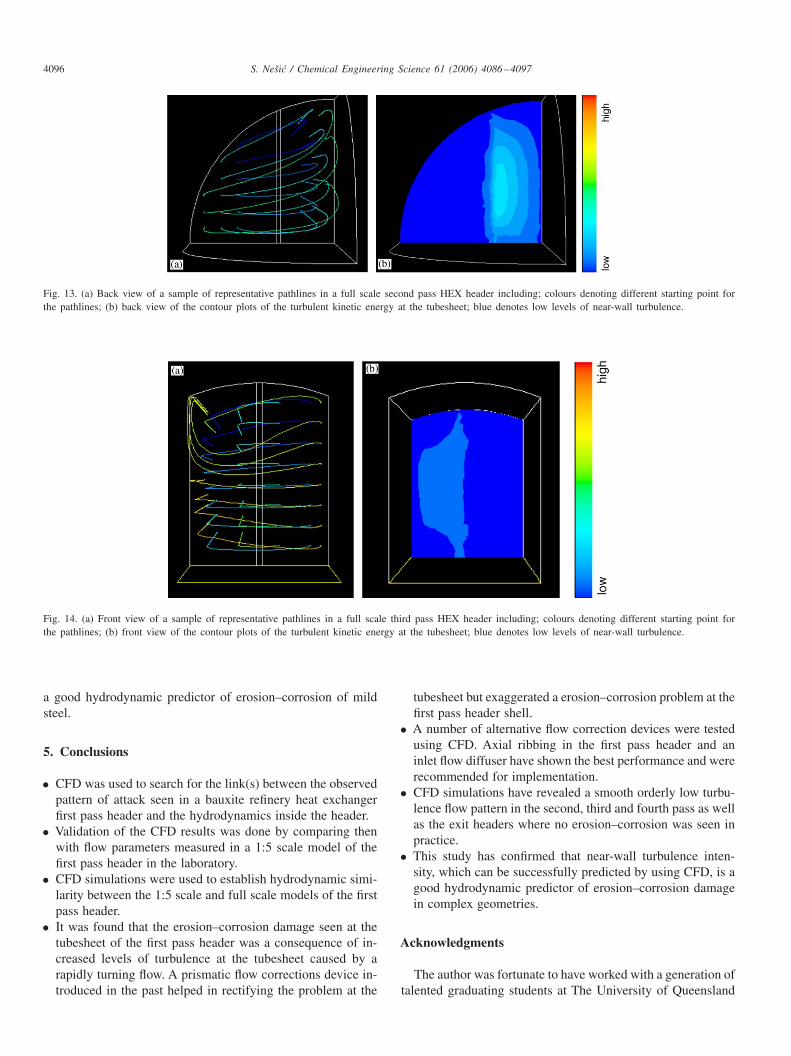
fourth and exit headers. This would explain the lack of dam-age in these headers and the sharp contrast with the first passheader. An investigation was undertaken by Ainsbury (2001)and indeed he discovered smooth undisturbed flow in all theremaining headers. As an illustration orderly smooth flow and
low levels of turbulence at the tubesheet can be seen in the sec-ond pass header (see Fig. 13) as well as the third pass header(see Fig. 14). Similar results were observed for the fourth passheader and the exit header. This finding confirmed the operat-ing assumption about the near-wall turbulence intensity being
4096 S. Nešic / Chemical Engineering Science 61 (2006) 4086–4097
Fig. 13. (a) Back view of a sample of representative pathlines in a full scale second pass HEX header including; colours denoting different starting point forthe pathlines; (b) back view of the contour plots of the turbulent kinetic energy at the tubesheet; blue denotes low levels of near-wall turbulence.
Fig. 14. (a) Front view of a sample of representative pathlines in a full scale third pass HEX header including; colours denoting different starting point forthe pathlines; (b) front view of the contour plots of the turbulent kinetic energy at the tubesheet; blue denotes low levels of near-wall turbulence.
a good hydrodynamic predictor of erosion–corrosion of mildsteel.
5. Conclusions
• CFD was used to search for the link(s) between the observedpattern of attack seen in a bauxite refinery heat exchangerfirst pass header and the hydrodynamics inside the header.
• Validation of the CFD results was done by comparing thenwith flow parameters measured in a 1:5 scale model of thefirst pass header in the laboratory.
• CFD simulations were used to establish hydrodynamic simi-larity between the 1:5 scale and full scale models of the firstpass header.
• It was found that the erosion–corrosion damage seen at thetubesheet of the first pass header was a consequence of in-creased levels of turbulence at the tubesheet caused by arapidly turning flow. A prismatic flow corrections device in-troduced in the past helped in rectifying the problem at the
tubesheet but exaggerated a erosion–corrosion problem at thefirst pass header shell.
• A number of alternative flow correction devices were testedusing CFD. Axial ribbing in the first pass header and aninlet flow diffuser have shown the best performance and wererecommended for implementation.
• CFD simulations have revealed a smooth orderly low turbu-lence flow pattern in the second, third and fourth pass as wellas the exit headers where no erosion–corrosion was seen inpractice.
• This study has confirmed that near-wall turbulence inten-sity, which can be successfully predicted by using CFD, is agood hydrodynamic predictor of erosion–corrosion damagein complex geometries.
Acknowledgments
The author was fortunate to have worked with a generation oftalented graduating students at The University of Queensland
S. Nešic / Chemical Engineering Science 61 (2006) 4086–4097 4097
Mechanical Engineering Department who were all (one wayor another) part of this effort. They are, in no particular order:Phillip M. Huber, Christopher Hutchins-Sach, Shane Coles,Ann M. Purchase, Steven Rode-Bramanis, Tarek Salameh,Michael P. Scott, Carlos A. Varela and Matthew P. Ainsbury.
References
Ainsbury, M.P., 2001. Computational investigation of erosion–corrosion inthe 2nd, 3rd and 4th pass header of a shell and tube heat exchanger.Undergraduate Thesis, University of Queensland, Brisbane.
Bremhorst, K., Flint, P.J., 1991. Wear 145, 123–135.Bremhorst, K., Lai, J.C.S., 1979. Wear 54, 87–100.Coles, S., 2000. Hydrodynamic investigation of erosion–corrosion in a shell
and tube heat exchanger header. Undergraduate Thesis, University ofQueensland, Brisbane.
Elvery, D.G., 1995. Erosion–corrosion in tube inlets as a consequence ofinclined flow into heat exchanges. Ph.D. Thesis, UQ, Brisbane.
Elvery, D.G., Bremhorst, K., 1997. Journal of Fluids Engineering 103,948–953.
Ferziger, J.H., Peric, M., 1996. Computational Methods for Fluid Dynamics.Springer, Berlin.
Fontana, M.G., 1986. Corrosion Engineering. third ed. McGraw-Hill BookCompany, USA.
Huber, P.M., 1999. CFD study of erosion–corrosion in a shell and tubeheat exchanger header. Undergraduate Thesis, University of Queensland,Brisbane.
King, F., 1987. Aluminium and its Alloys. Ellis Horwood Limited, Chichester,UK, pp. 39–44.
Lai, J.C.S., 1977. Hydrodynamic aspects of erosion–corrosion of tube inletsof shell and tube heat exchanges. Masters Thesis, UQ, Brisbane.
Lai, J.C.S., Bremhorst, K., 1979. Wear 54, 101–112.Nešic, S., Postlethwaite, J., 1990. Corrosion 46 (11), 874–880.Patankar, S.V., 1980. Numerical Heat Transfer and Fluid Flow. McGraw-Hill
Book Company, New York.Purchase, A., 2000. CFD investigation of erosion–corrosion in the first pass
of a shell and tube heat exchanger. Undergraduate Thesis, University ofQueensland, Brisbane.
Rode-Bramanis, S. 2000. Investigation into the hydrodynamic parameterscontributing to erosion–corrosion in a shell and tube heat exchanger header.Undergraduate Thesis, University of Queensland, Brisbane.
Salameh, T., 2001. Computational fluid dynamics investigation oferosion–corrosion in a heat exchanger header. Undergraduate Thesis,University of Queensland, Brisbane.
Scott, A., 2001. Computational fluid dynamics investigation oferosion–corrosion in a heat exchanger header. Undergraduate Thesis,University of Queensland, Brisbane.
Varela, C., 2000. Report of UQ research on erosion–corrosion damage ina shell and tube heat exchanger. Vacation Work Report, University ofQueensland, Brisbane.
Varela, C., 2001. Computational fluid dynamics study of erosion–corrosionon shell-and-tube exchanger tube inlets. Undergraduate Thesis, Universityof Queensland, Brisbane.
Versteeg, H.K., Malalasekera, W., 1995. An Introduction to ComputationalFluid Dynamics. Longman, White Plains, NY.
Further Reading
Hutchins-Sach, C., 1999. Computational investigation of erosion–corrosion ina tube and shell heat exchanger header. Undergraduate Thesis, Universityof Queensland, Brisbane.
![Numerical Heat Transfer and Fluid FLow [Patankar]](https://static.fdocuments.us/doc/165x107/55cf8fea550346703ba13647/numerical-heat-transfer-and-fluid-flow-patankar-569a3a8a8d259.jpg)