
Using uM-FPU V3.1 with the PICAXE Microcontroller … · Micromega Corporation 5 Using the uM-FPU...
26
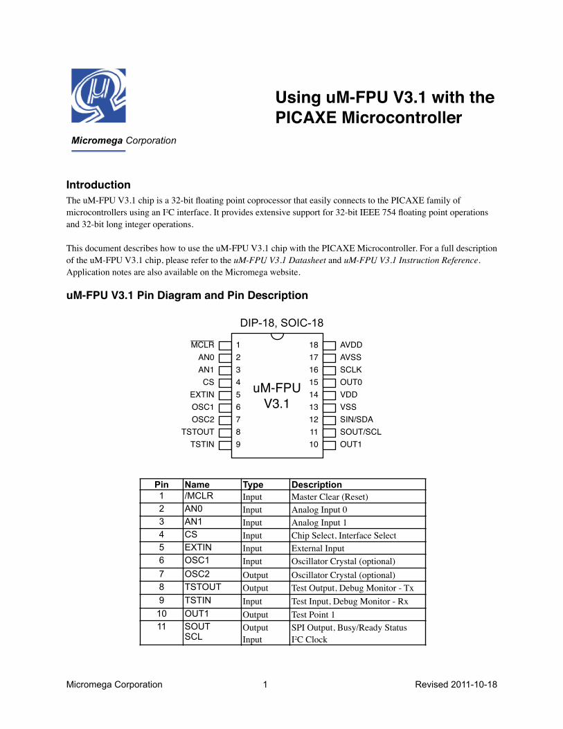
Micromega Corporation 1 Revised 2011-10-18 Using uM-FPU V3.1 with the PICAXE Microcontroller Introduction The uM-FPU V3.1 chip is a 32-bit floating point coprocessor that easily connects to the PICAXE family of microcontrollers using an I 2 C interface. It provides extensive support for 32-bit IEEE 754 floating point operations and 32-bit long integer operations. This document describes how to use the uM-FPU V3.1 chip with the PICAXE Microcontroller. For a full description of the uM-FPU V3.1 chip, please refer to the uM-FPU V3.1 Datasheet and uM-FPU V3.1 Instruction Reference. Application notes are also available on the Micromega website. uM-FPU V3.1 Pin Diagram and Pin Description DIP-18, SOIC-18 uM-FPU V3.1 1 2 3 4 5 6 7 8 9 18 17 16 15 14 13 12 11 10 AVDD AVSS SCLK OUT0 VDD VSS SIN/SDA SOUT/SCL OUT1 AN0 AN1 CS EXTIN OSC1 OSC2 TSTOUT TSTIN MCLR Pin 1 2 3 4 5 6 7 8 9 10 11 Name /MCLR AN0 AN1 CS EXTIN OSC1 OSC2 TSTOUT TSTIN OUT1 SOUT SCL Type Input Input Input Input Input Input Output Output Input Output Output Input Description Master Clear (Reset) Analog Input 0 Analog Input 1 Chip Select, Interface Select External Input Oscillator Crystal (optional) Oscillator Crystal (optional) Test Output, Debug Monitor - Tx Test Input, Debug Monitor - Rx Test Point 1 SPI Output, Busy/Ready Status I 2 C Clock
-
Upload
nguyenmien -
Category
Documents
-
view
221 -
download
0
Transcript of Using uM-FPU V3.1 with the PICAXE Microcontroller … · Micromega Corporation 5 Using the uM-FPU...
Micromega Corporation 1 Revised 2011-10-18
Using uM-FPU V3.1 with the PICAXE Microcontroller
IntroductionThe uM-FPU V3.1 chip is a 32-bit floating point coprocessor that easily connects to the PICAXE family of microcontrollers using an I2C interface. It provides extensive support for 32-bit IEEE 754 floating point operations and 32-bit long integer operations.
This document describes how to use the uM-FPU V3.1 chip with the PICAXE Microcontroller. For a full description of the uM-FPU V3.1 chip, please refer to the uM-FPU V3.1 Datasheet and uM-FPU V3.1 Instruction Reference. Application notes are also available on the Micromega website.
uM-FPU V3.1 Pin Diagram and Pin Description
DIP-18, SOIC-18
uM-FPUV3.1
123456789
181716151413121110
AVDDAVSSSCLKOUT0VDDVSSSIN/SDASOUT/SCLOUT1
AN0AN1CS
EXTINOSC1OSC2
TSTOUTTSTIN
MCLR
Pin123456789
1011
Name/MCLRAN0AN1CSEXTINOSC1OSC2TSTOUTTSTINOUT1SOUTSCL
TypeInputInputInputInputInputInputOutputOutputInputOutputOutputInput
DescriptionMaster Clear (Reset)Analog Input 0Analog Input 1Chip Select, Interface SelectExternal InputOscillator Crystal (optional)Oscillator Crystal (optional)Test Output, Debug Monitor - TxTest Input, Debug Monitor - Rx Test Point 1SPI Output, Busy/Ready StatusI2C Clock

Micromega Corporation 2 Using the uM-FPU V3.1 with the PICAXE
Connecting uM-FPU V3.1 to the PICAXE using I2CThe default slave address for the uM-FPU V3.1 chip is 0xC8 (LSB is the R/W bit, e.g. 0xC8 for write, 0xC9 for read). See the uM-FPU datasheet for further description of the I2C interface. See the PICAXE documentation to determine the location of the I2C pins for each different microcontroller.
PICAXE-18X I2C SDA Output 1I2C SCL Output 4
/MCLRAN0AN1CSEXTINOSC1OSC2TSTOUTTSTIN
AVDDAVSSSCLKOUT0VDDVSS
SIN/SDASOUT/SCL
OUT1
uM-FPU V3.1123456789
181716151413121110
VDDVDD
Output 4 SCLOutput 1 SDA
Note: SCL and SDA must have pull-up resistors as required by the I2C bus.
PICAXE Pins
12
131415161718
SINSDAVSSVDDOUT0SCLKAVSSAVDD
InputIn/OutPowerPowerOutputInputPowerPower
SPI InputI2C DataDigital GroundDigital Supply VoltageTest Point 0SPI ClockAnalog GroundAnalog Supply Voltage
Micromega Corporation 3 Using the uM-FPU V3.1 with the PICAXE
Brief Overview of the uM-FPU V3.1 chipFor a full description of the uM-FPU V3.1 chip, please refer to the uM-FPU V3.1 Datasheet, uM-FPU V3.1 Instruction Reference. Application notes are also available on the Micromega website.
The uM-FPU V3.1 chip is a separate coprocessor with its own set of registers and instructions designed to provide microcontrollers with 32-bit floating point and long integer capabilities. The PICAXE communicates with the FPU using a SPI or I2C interface. Instructions and data are sent to the FPU, and the FPU performs the calculations. The PICAXE is free to do other tasks while the FPU performs calculations. Results can be read back to the PICAXE or stored on the FPU for later use. The uM-FPU V3.1 chip has 128 registers, numbered 0 through 127, that can hold 32-bit floating point or long integer values. Register 0 is often used as a temporary register and is modified by some of the FPU instructions. Registers 1 through 127 are available for general use.
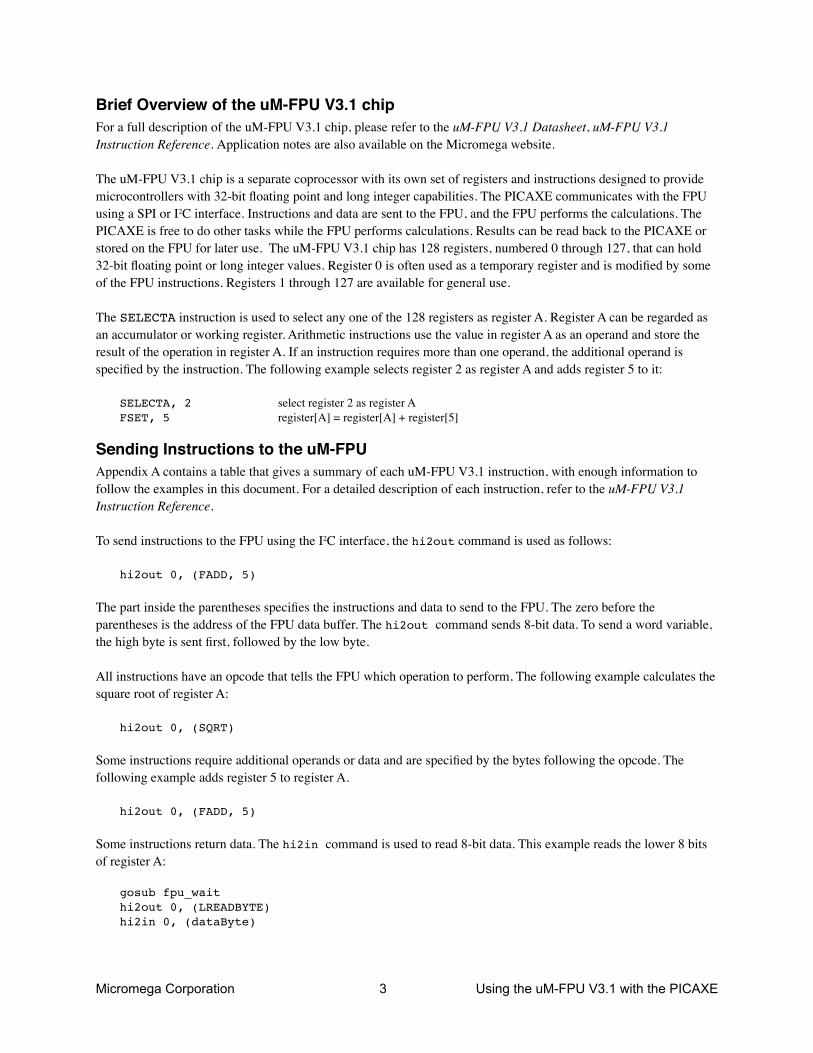
The SELECTA instruction is used to select any one of the 128 registers as register A. Register A can be regarded as an accumulator or working register. Arithmetic instructions use the value in register A as an operand and store the result of the operation in register A. If an instruction requires more than one operand, the additional operand is specified by the instruction. The following example selects register 2 as register A and adds register 5 to it:
SELECTA, 2 select register 2 as register AFSET, 5 register[A] = register[A] + register[5]
Sending Instructions to the uM-FPUAppendix A contains a table that gives a summary of each uM-FPU V3.1 instruction, with enough information to follow the examples in this document. For a detailed description of each instruction, refer to the uM-FPU V3.1 Instruction Reference.
To send instructions to the FPU using the I2C interface, the hi2out command is used as follows:
hi2out 0, (FADD, 5)
The part inside the parentheses specifies the instructions and data to send to the FPU. The zero before the parentheses is the address of the FPU data buffer. The hi2out command sends 8-bit data. To send a word variable, the high byte is sent first, followed by the low byte.
All instructions have an opcode that tells the FPU which operation to perform, The following example calculates the square root of register A:
hi2out 0, (SQRT)
Some instructions require additional operands or data and are specified by the bytes following the opcode. The following example adds register 5 to register A.
hi2out 0, (FADD, 5)
Some instructions return data. The hi2in command is used to read 8-bit data. This example reads the lower 8 bits of register A:
gosub fpu_waithi2out 0, (LREADBYTE)hi2in 0, (dataByte)

Micromega Corporation 4 Using the uM-FPU V3.1 with the PICAXE
The following example adds the value in register 5 to the value in register 2.
hi2out 0, (SELECTA, 2, FADD, 5)
It’s a good idea to use constant definitions to provide meaningful names for the registers. This makes your program code easier to read and understand. The same example using constant definitions would be:
symbol Total = 2 ' total amount (uM-FPU register)symbol Count = 5 ' current count (uM-FPU register)
hi2out 0, (SELECTA, Total, FADD, Count)
Micromega Corporation 5 Using the uM-FPU V3.1 with the PICAXE
Tutorial ExamplesNow that we’ve introduced some of the basic concepts of sending instructions to the FPU, let’s go through a tutorial example to get a better understanding of how it all ties together. This example takes a temperature reading from a DS1620 digital thermometer and converts it to Celsius and Fahrenheit.
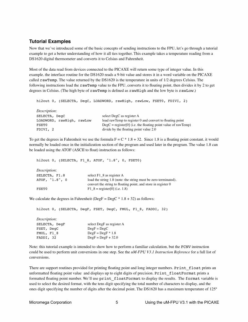
Most of the data read from devices connected to the PICAXE will return some type of integer value. In this example, the interface routine for the DS1620 reads a 9-bit value and stores it in a word variable on the PICAXE called rawTemp. The value returned by the DS1620 is the temperature in units of 1/2 degrees Celsius. The following instructions load the rawTemp value to the FPU, converts it to floating point, then divides it by 2 to get degrees in Celsius. (The high byte of rawTemp is defined as rawHigh and the low byte is rawLow.)
hi2out 0, (SELECTA, DegC, LOADWORD, rawHigh, rawLow, FSET0, FDIVI, 2)
Description:SELECTA, DegC select DegC as register ALOADWORD, rawHigh, rawLow load rawTemp to register 0 and convert to floating pointFSET0 DegC = register[0] (i.e. the floating point value of rawTemp)FDIVI, 2 divide by the floating point value 2.0
To get the degrees in Fahrenheit we use the formula F = C * 1.8 + 32. Since 1.8 is a floating point constant, it would normally be loaded once in the initialization section of the program and used later in the program. The value 1.8 can be loaded using the ATOF (ASCII to float) instruction as follows:
hi2out 0, (SELECTA, F1_8, ATOF, "1.8", 0, FSET0)
Description:SELECTA, F1.8 select F1_8 as register AATOF, "1.8", 0 load the string 1.8 (note: the string must be zero terminated),
convert the string to floating point, and store in register 0FSET0 F1_8 = register[0] (i.e. 1.8)
We calculate the degrees in Fahrenheit (DegF = DegC * 1.8 + 32) as follows:
hi2out 0, (SELECTA, DegF, FSET, DegC, FMUL, F1_8, FADDI, 32)
Description:SELECTA, DegF select DegF as register AFSET, DegC DegF = DegCFMUL, F1_8 DegF = DegF * 1.8FADDI, 32 DegF = DegF + 32.0
Note: this tutorial example is intended to show how to perform a familiar calculation, but the FCNV instruction could be used to perform unit conversions in one step. See the uM-FPU V3.1 Instruction Reference for a full list of conversions.
There are support routines provided for printing floating point and long integer numbers. Print_float prints an unformatted floating point value and displays up to eight digits of precision. Print_floatFormat prints a formatted floating point number. We’ll use print_floatFormat to display the results. The format variable is used to select the desired format, with the tens digit specifying the total number of characters to display, and the ones digit specifying the number of digits after the decimal point. The DS1620 has a maximum temperature of 125°
Micromega Corporation 6 Using the uM-FPU V3.1 with the PICAXE
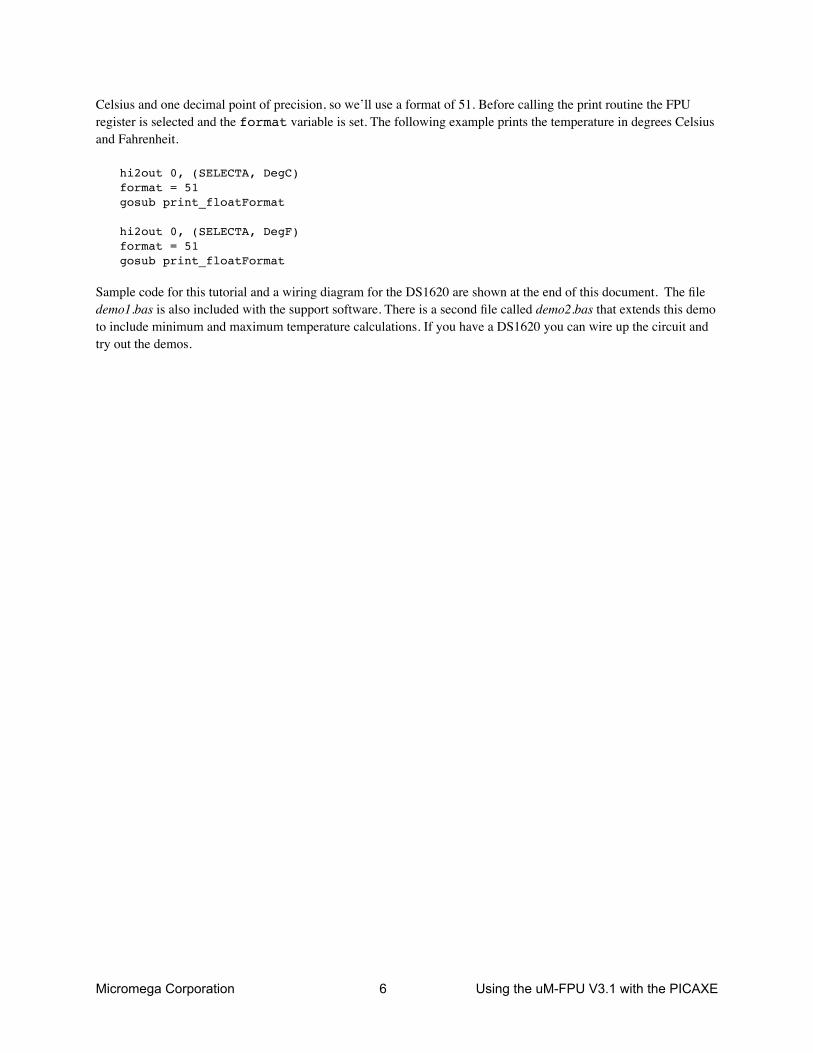
Celsius and one decimal point of precision, so we’ll use a format of 51. Before calling the print routine the FPU register is selected and the format variable is set. The following example prints the temperature in degrees Celsius and Fahrenheit.
hi2out 0, (SELECTA, DegC)format = 51gosub print_floatFormat
hi2out 0, (SELECTA, DegF)format = 51gosub print_floatFormat
Sample code for this tutorial and a wiring diagram for the DS1620 are shown at the end of this document. The file demo1.bas is also included with the support software. There is a second file called demo2.bas that extends this demo to include minimum and maximum temperature calculations. If you have a DS1620 you can wire up the circuit and try out the demos.

Micromega Corporation 7 Using the uM-FPU V3.1 with the PICAXE
uM-FPU Support Software for the PICAXE MicrocontrollerA template file contains all of the definitions and support code required for communicating with theuM-FPU V3.1 chip:
template.bas provides support for an I2C connection to the uM-FPU V3.1 chip
This file can be used directly as the starting point for a new program, or the definitions and support code can be copied to another program. It contains the following:
• pin definitions for the uM-FPU V3.1• opcode definitions for all uM-FPU V3.1 instructions• various definitions for the byte variable used by the support routines• a sample program with a place to insert your application code• the support routines described below
fpu_resetTo ensure that the PICAXE and the FPU coprocessor are synchronized, a reset call must be done at the start of every program. The fpu_reset routine resets the FPU, confirms communications, and returns the sync character 0x5C if the reset is successful. A sample reset call is included in the template.bas file.
fpu_waitThe uM-FPU V3.1 chip must have completed all instructions in the instruction buffer, and be ready to return data, before sending an instruction to read data from the FPU. The Fpu_Wait routine checks the status of the FPU and waits until it is ready. The print routines check the ready status, so it isn’t necessary to call Fpu_Wait before calling a print routine, but if your program reads directly from the FPU using the hi2in command, a call to Fpu_Wait must be made prior to sending the read instruction. An example of reading a byte value is as follows:
gosub fpu_waithi2out 0, (LREADBYTE)hi2in 0, (dataByte)
Description:• wait for the FPU to be ready• send the LREADBYTE instruction • read a byte value
The uM-FPU V3.1 chip has a 256 byte instruction buffer. In most cases, data will be read back before 256 bytes have been sent to the FPU. If a long calculation is done that requires more than 256 bytes to be sent to the FPU, an Fpu_Wait call should be made at least every 256 bytes to ensure that the instruction buffer doesn’t overflow.
fpu_readStatusThe current status byte is read from the FPU and returned in the statusByte variable.
print_floatThe value in register A is displayed on the PC screen as a floating point value using the sertxd command. Up to eight significant digits will be displayed if required. Very large or very small numbers are displayed in exponential notation. The length of the displayed value is variable and can be from 3 to 12 characters in length. The special cases of NaN (Not a Number), +Infinity, -Infinity, and -0.0 are handled. Examples of the display format are as follows:
1.0 NaN 0.01.5e20 Infinity -0.03.1415927 -Infinity 1.0

Micromega Corporation 8 Using the uM-FPU V3.1 with the PICAXE
-52.333334 -3.5e-5 0.01
print_floatFormatThe value in register A is displayed on the PC screen as a formatted floating point value using the sertxd command. The format byte is used to specify the desired format. The tens digit specifies the total number of characters to display and the ones digit specifies the number of digits after the decimal point. If the value is too large for the format specified, then asterisks will be displayed. If the number of digits after the decimal points is zero, no decimal point will be displayed. Examples of the display format are as follows:
Value in A register format Display format123.567 61 (6.1) 123.6123.567 62 (6.2) 123.57123.567 42 (4.2) *.**0.9999 20 (2.0) 10.9999 31 (3.1) 1.0
print_longThe value in register A is displayed on the PC screen as a signed long integer using the sertxd command. The displayed value can range from 1 to 11 characters in length. Examples of the display format are as follows:
1500000-3598390
print_longFormatThe value in register A is displayed on the PC screen as a formatted long integer using the sertxd command. The format byte is used to specify the desired format. A value between 0 and 15 specifies the width of the display field for a signed long integer. The number is displayed right justified. If 100 is added to the format value the value is displayed as an unsigned long integer. If the value is larger than the specified width, asterisks will be displayed. If the width is specified as zero, the length will be variable. Examples of the display format are as follows:
Value in register A format Display format-1 10 (signed 10) -1-1 110 (unsigned 10) 4294967295-1 4 (signed 4) -1-1 104 (unsigned 4) ****0 4 (signed 4) 00 0 (unformatted) 01000 6 (signed 6) 1000
print_versionThe uM-FPU V3.1 version string is displayed on the PC screen using the sertxd command.
print_fpuStringThe contents of the uM-FPU V3.1 string buffer are displayed to the PC screen using the sertxd command. This call is made at the end of the print_float, print_floatFormat, print_long and print_longFormat routines so is not normally called directly by the user unless string instructions are being used directly.
Micromega Corporation 9 Using the uM-FPU V3.1 with the PICAXE
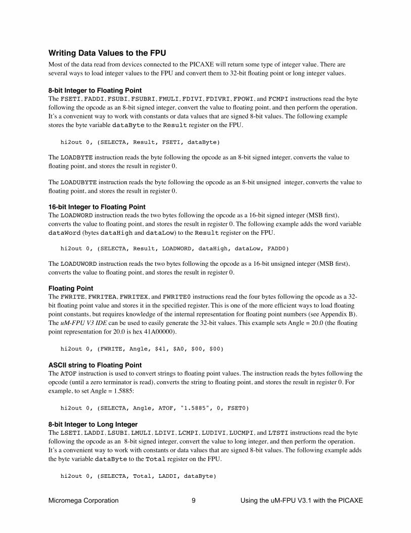
Writing Data Values to the FPUMost of the data read from devices connected to the PICAXE will return some type of integer value. There are several ways to load integer values to the FPU and convert them to 32-bit floating point or long integer values.
8-bit Integer to Floating PointThe FSETI, FADDI, FSUBI, FSUBRI, FMULI, FDIVI, FDIVRI, FPOWI, and FCMPI instructions read the byte following the opcode as an 8-bit signed integer, convert the value to floating point, and then perform the operation. It’s a convenient way to work with constants or data values that are signed 8-bit values. The following example stores the byte variable dataByte to the Result register on the FPU.
hi2out 0, (SELECTA, Result, FSETI, dataByte)
The LOADBYTE instruction reads the byte following the opcode as an 8-bit signed integer, converts the value to floating point, and stores the result in register 0.
The LOADUBYTE instruction reads the byte following the opcode as an 8-bit unsigned integer, converts the value to floating point, and stores the result in register 0.
16-bit Integer to Floating PointThe LOADWORD instruction reads the two bytes following the opcode as a 16-bit signed integer (MSB first), converts the value to floating point, and stores the result in register 0. The following example adds the word variable dataWord (bytes dataHigh and dataLow) to the Result register on the FPU.
hi2out 0, (SELECTA, Result, LOADWORD, dataHigh, dataLow, FADD0)
The LOADUWORD instruction reads the two bytes following the opcode as a 16-bit unsigned integer (MSB first), converts the value to floating point, and stores the result in register 0.
Floating PointThe FWRITE, FWRITEA, FWRITEX, and FWRITE0 instructions read the four bytes following the opcode as a 32-bit floating point value and stores it in the specified register. This is one of the more efficient ways to load floating point constants, but requires knowledge of the internal representation for floating point numbers (see Appendix B). The uM-FPU V3 IDE can be used to easily generate the 32-bit values. This example sets Angle = 20.0 (the floating point representation for 20.0 is hex 41A00000).
hi2out 0, (FWRITE, Angle, $41, $A0, $00, $00)
ASCII string to Floating PointThe ATOF instruction is used to convert strings to floating point values. The instruction reads the bytes following the opcode (until a zero terminator is read), converts the string to floating point, and stores the result in register 0. For example, to set Angle = 1.5885:
hi2out 0, (SELECTA, Angle, ATOF, "1.5885", 0, FSET0)
8-bit Integer to Long IntegerThe LSETI, LADDI, LSUBI, LMULI, LDIVI, LCMPI, LUDIVI, LUCMPI, and LTSTI instructions read the byte following the opcode as an 8-bit signed integer, convert the value to long integer, and then perform the operation. It’s a convenient way to work with constants or data values that are signed 8-bit values. The following example adds the byte variable dataByte to the Total register on the FPU.
hi2out 0, (SELECTA, Total, LADDI, dataByte)

Micromega Corporation 10 Using the uM-FPU V3.1 with the PICAXE
The LONGBYTE instruction reads the byte following the opcode as an 8-bit signed integer, converts the value to long integer, and stores the result in register 0.
The LONGUBYTE instruction reads the byte following the opcode as an 8-bit unsigned integer, converts the value to long integer, and stores the result in register 0.
16-bit Integer to Long IntegerThe LONGWORD instruction reads the two bytes following the opcode as a 16-bit signed integer (MSB first), converts the value to long integer, and stores the result in register 0. The following example adds the word variable dataWord to the Total register on the FPU.
hi2out 0, (SELECTA, Total, LONGWORD, dataHigh, dataLow, LADD0)
The LONGUWORD instruction reads the two bytes following the opcode as a 16-bit unsigned integer (MSB first), converts the value to long integer, and stores the result in register 0.
Long IntegerThe LWRITE, LWRITEA, LWRITEX, and LWRITE0 instructions read the four bytes following the opcode as a 32-bit long integer value and stores it in the specified register. This is used to load integer values greater than 16 bits. The uM-FPU V3 IDE can be used to easily generate the 32-bit values. For example, to set Total = 500000:
hi2out 0, (LWRITE, Total, $00, $07, $A1, $20)
ASCII string to Long IntegerThe ATOL instruction is used to convert strings to long integer values. The instruction reads the bytes following the opcode (until a zero terminator is read), converts the string to long integer, and stores the result in register 0. For example, to set Total = 500000:
hi2out 0, (SELECTA, Total, ATOL, "5000000", 0, FSET0)
The fastest operations occur when the FPU registers are already loaded with values. In time critical portions of code floating point constants should be loaded beforehand to maximize the processing speed in the critical section. With 128 registers available on the FPU, it’s often possible to pre-load all of the required constants. In non-critical sections of code, data and constants can be loaded as required.
Reading Data Values from the FPUThe uM-FPU V3.1 chip has a 256 byte instruction buffer which allows data transmission to continue while previous instructions are being executed. Before reading data, you must check to ensure that the previous commands have completed, and the FPU is ready to send data. The Fpu_Wait routine is used to wait until the FPU is ready, then a read command is sent, and the hi2in command is used to read data.
Floating PointThe FREAD, FREADA, FREADX, and FREAD0 instructions read four bytes from the FPU as a 32-bit floating point value. The following example reads the 32-bit floating point value from register A and stores it in byte variables byte0, byte1, byte2, and byte3.
gosub Fpu_waithi2out 0, (FREADA)hi2in 0, (byte0, byte1, byte2, byte3)

Micromega Corporation 11 Using the uM-FPU V3.1 with the PICAXE
Floating Point to ASCII stringThe FTOA instruction can be used to convert floating point values to an ASCII string. The print_float and print_floatFormat routines use this instruction to read the floating point value from register A and display it on the PC screen.
8-bit IntegerThe LREADBYTE instruction reads the lower 8 bits from register A. The following example stores the lower 8 bits of register A in byte variable dataByte.
gosub Fpu_waithi2out 0, (LREADBYTE)hi2in 0, (dataByte)
16-bit IntegerThe LREADWORD instruction reads the lower 16 bits from register A. The following example stores the lower 16 bits of register A in word variable dataWord (bytes dataHigh and dataLow).
gosub Fpu_waithi2out 0, (LREADWORD)hi2in 0, (dataHigh, dataLow)
Long IntegerThe LREAD, LREADA, LREADX, and LREAD0 instructions read four bytes from the FPU as a 32-bit long integer value. The following example reads the 32-bit long integer value from register A and stores it in byte variables byte0, byte1, byte2, and byte3.
gosub Fpu_waithi2out 0, (LREADA)hi2in 0, (byte0, byte1, byte2, byte3)
Long Integer to ASCII stringThe LTOA instruction can be used to convert long integer values to an ASCII string. The print_long and print_longFormat routines use this instruction to read the long integer value from register A and display it on the PC screen.
Comparing and Testing Floating Point ValuesFloating point values can be zero, positive, negative, infinite, or Not a Number (which occurs if an invalid operation is performed on a floating point value). The status byte is read using the Fpu_ReadStatus routine. It waits for the FPU to be ready before sending the READSTATUS instruction and reading the status from the FPU. The current status is returned in the statusByte variable. Definitions for the status bits are provided as follows:
symbol IS_ZERO = 0x81 ' positive zerosymbol IS_NZERO = 0x83 ' negative zerosymbol IS_NEGATIVE = 0x82 ' negativesymbol IS_NAN = 0x84 ' NaN (Not-a-Number)symbol IS_PINF = 0x88 ' positive infinitysymbol IS_NINF = 0x8A ' negative infinity
The FSTATUS and FSTATUSA instructions are used to set the status byte to the floating point status of the selected register. The following example checks the floating point status of register A:
hi2out 0, (FSTATUSA)gosub fpu_readStatus

Micromega Corporation 12 Using the uM-FPU V3.1 with the PICAXE
IF statusByte = IS_ZERO or statusByte = IS_NZERO then zeroValueIF statusByte = IS_NEGATIVE then negativeValue sertxd("value is positive") …negativeValue: sertxd("value is negative") …zeroValue: sertxd("value is zero")
The FCMP, FCMP0, and FCMPI instructions are used to compare two floating point values. The status bits are set for the result of register A minus the operand (the selected registers are not modified). For example, to compare register A to the value 10.0:
hi2out 0, (FCMPI, 10)gosub fpu_readStatusIF statusByte = IS_ZERO then sameAsIF statusByte = IS_NEGATIVE then lessThan sertxd("A > 10") …lessThan: sertxd("A < 10") …sameAs: sertxd("A = 10")
The FCMP2 instruction compares two floating point registers. The status bits are set for the result of the first register minus the second register (the selected registers are not modified). For example, to compare registers Value1 and Value2:
hi2out 0, (FCMP2, Value1, Value2)gosub fpu_readStatus…
Comparing and Testing Long Integer ValuesA long integer value can be zero, positive, or negative. The status byte is read using the Fpu_ReadStatus routine. It waits for the FPU to be ready before sending the READSTATUS command and reading the status. The current status is returned in the statusByte variable. Definitions for the status bits are provided as follows:
symbol IS_ZERO = 0x81 ' zerosymbol IS_NEGATIVE = 0x82 ' negative
The LSTATUS and LSTATUSA instructions are used to set the status byte to the long integer status of the selected register. The following example checks the long integer status of register A:
hi2out 0, (LSTATUSA)IF statusByte = IS_ZERO then zeroValueIF statusByte = IS_NEGATIVE then negativeValue sertxd("value is positive") …negativeValue: sertxd("value is negative") …zeroValue: sertxd("value is zero")
Micromega Corporation 13 Using the uM-FPU V3.1 with the PICAXE
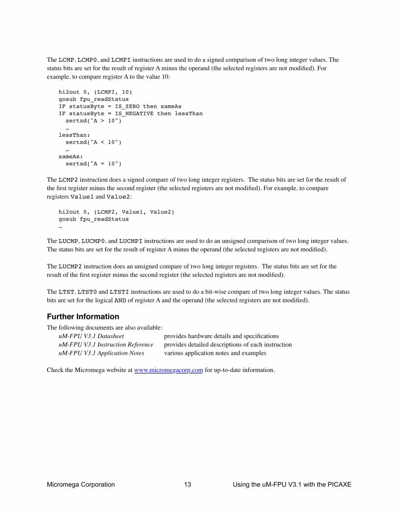
The LCMP, LCMP0, and LCMPI instructions are used to do a signed comparison of two long integer values. The status bits are set for the result of register A minus the operand (the selected registers are not modified). For example, to compare register A to the value 10:
hi2out 0, (LCMPI, 10)gosub fpu_readStatusIF statusByte = IS_ZERO then sameAsIF statusByte = IS_NEGATIVE then lessThan sertxd("A > 10") …lessThan: sertxd("A < 10") …sameAs: sertxd("A = 10")
The LCMP2 instruction does a signed compare of two long integer registers. The status bits are set for the result of the first register minus the second register (the selected registers are not modified). For example, to compare registers Value1 and Value2:
hi2out 0, (LCMP2, Value1, Value2)gosub fpu_readStatus…
The LUCMP, LUCMP0, and LUCMPI instructions are used to do an unsigned comparison of two long integer values. The status bits are set for the result of register A minus the operand (the selected registers are not modified).
The LUCMP2 instruction does an unsigned compare of two long integer registers. The status bits are set for the result of the first register minus the second register (the selected registers are not modified).
The LTST, LTST0 and LTSTI instructions are used to do a bit-wise compare of two long integer values. The status bits are set for the logical AND of register A and the operand (the selected registers are not modified).
Further InformationThe following documents are also available:
uM-FPU V3.1 Datasheet provides hardware details and specificationsuM-FPU V3.1 Instruction Reference provides detailed descriptions of each instructionuM-FPU V3.1 Application Notes various application notes and examples
Check the Micromega website at www.micromegacorp.com for up-to-date information.
Micromega Corporation 14 Using the uM-FPU V3.1 with the PICAXE
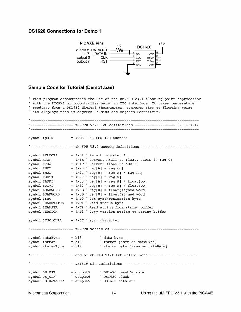
DS1620 Connections for Demo 1
DQ
CLK
RST
GND
VDD
THIGH
TLOW
TCOM
DS1620
18
17
16
15
1
2
3
4
1K
input 7 DATA INoutput 6 CLK
PICAXE Pins
output 7 RST
+5V
output 5 DATAOUT
Sample Code for Tutorial (Demo1.bas)
' This program demonstrates the use of the uM-FPU V3.1 floating point coprocessor' with the PICAXE microcontroller using an I2C interface. It takes temperature' readings from a DS1620 digital thermometer, converts them to floating point' and displays them in degrees Celsius and degrees Fahrenheit.
'==============================================================================='-------------------- uM-FPU V3.1 I2C definitions ------------------- 2011-10-17'===============================================================================
symbol fpuID = 0xC8 ' uM-FPU I2C address
'-------------------- uM-FPU V3.1 opcode definitions ---------------------------
symbol SELECTA = 0x01 ' Select register Asymbol ATOF = 0x1E ' Convert ASCII to float, store in reg[0]symbol FTOA = 0x1F ' Convert float to ASCIIsymbol FSET = 0x20 ' reg[A] = reg[nn]symbol FMUL = 0x24 ' reg[A] = reg[A] * reg[nn]symbol FSET0 = 0x29 ' reg[A] = reg[0]symbol FADDI = 0x33 ' reg[A] = reg[A] + float(bb)symbol FDIVI = 0x37 ' reg[A] = reg[A] / float(bb)symbol LOADWORD = 0x5B ' reg[0] = float(signed word)symbol LOADWORD = 0x5B ' reg[0] = float(signed word)symbol SYNC = 0xF0 ' Get synchronization bytesymbol READSTATUS = 0xF1 ' Read status bytesymbol READSTR = 0xF2 ' Read string from string buffersymbol VERSION = 0xF3 ' Copy version string to string buffer
symbol SYNC_CHAR = 0x5C ' sync character
'-------------------- uM-FPU variables -----------------------------------------
symbol dataByte = b13 ' data bytesymbol format = b13 ' format (same as dataByte)symbol statusByte = b13 ' status byte (same as dataByte)
'==================== end of uM-FPU V3.1 I2C definitions =======================
'-------------------- DS1620 pin definitions ---------------------------------
symbol DS_RST = output7 ' DS1620 reset/enablesymbol DS_CLK = output6 ' DS1620 clocksymbol DS_DATAOUT = output5 ' DS1620 data out
Micromega Corporation 15 Using the uM-FPU V3.1 with the PICAXE
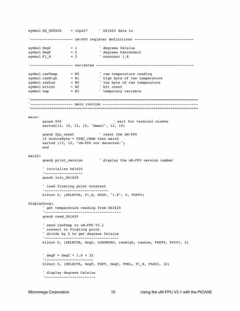
symbol DS_DATAIN = input7 ' DS1620 data in
'-------------------- uM-FPU register definitions ----------------------------
symbol DegC = 1 ' degrees Celsiussymbol DegF = 2 ' degrees Fahrenheitsymbol F1_8 = 3 ' constant 1.8
'-------------------- variables ----------------------------------------------
symbol rawTemp = W0 ' raw temperature readingsymbol rawHigh = B1 ' high byte of raw temperaturesymbol rawLow = B0 ' low byte of raw temperaturesymbol bitcnt = B2 ' bit countsymbol tmp = B3 ' temporary variable
'==============================================================================='-------------------- main routine ---------------------------------------------'===============================================================================
main:pause 500 ' wait for terminal windowsertxd(13, 10, 13, 10, "demo1", 13, 10)
gosub fpu_reset ' reset the uM-FPUif statusByte = SYNC_CHAR then main2sertxd (13, 10, "uM-FPU not detected.")end
main2:gosub print_version ' display the uM-FPU version number
' initialize DS1620'------------------gosub init_DS1620
' load floating point constant'------------------------------hi2out 0, (SELECTA, F1_8, ATOF, "1.8", 0, FSET0)
displayLoop:' get temperature reading from DS1620'------------------------------------gosub read_DS1620
' send rawTemp to uM-FPU V3.1' convert to floating point' divide by 2 to get degrees Celsius'-----------------------------------hi2out 0, (SELECTA, DegC, LOADWORD, rawHigh, rawLow, FSET0, FDIVI, 2)
' degF = degC * 1.8 + 32'-----------------------hi2out 0, (SELECTA, DegF, FSET, DegC, FMUL, F1_8, FADDI, 32)
' display degrees Celsius'------------------------
Micromega Corporation 16 Using the uM-FPU V3.1 with the PICAXE
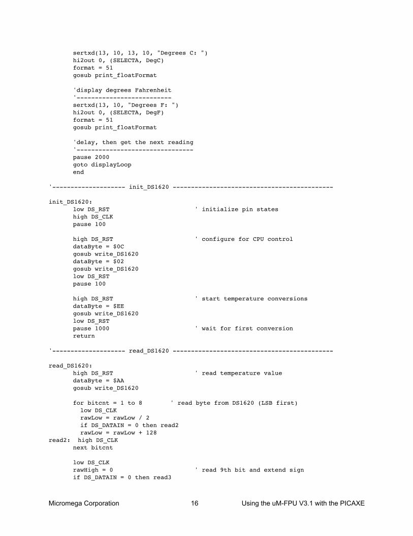
sertxd(13, 10, 13, 10, "Degrees C: ")hi2out 0, (SELECTA, DegC)format = 51gosub print_floatFormat
'display degrees Fahrenheit'--------------------------sertxd(13, 10, "Degrees F: ")hi2out 0, (SELECTA, DegF)format = 51gosub print_floatFormat
'delay, then get the next reading'--------------------------------pause 2000goto displayLoopend
'-------------------- init_DS1620 --------------------------------------------
init_DS1620:low DS_RST ' initialize pin stateshigh DS_CLKpause 100
high DS_RST ' configure for CPU controldataByte = $0Cgosub write_DS1620dataByte = $02gosub write_DS1620low DS_RSTpause 100
high DS_RST ' start temperature conversionsdataByte = $EEgosub write_DS1620low DS_RSTpause 1000 ' wait for first conversionreturn
'-------------------- read_DS1620 --------------------------------------------
read_DS1620:high DS_RST ' read temperature valuedataByte = $AAgosub write_DS1620
for bitcnt = 1 to 8 ' read byte from DS1620 (LSB first) low DS_CLK rawLow = rawLow / 2 if DS_DATAIN = 0 then read2 rawLow = rawLow + 128
read2: high DS_CLKnext bitcnt
low DS_CLKrawHigh = 0 ' read 9th bit and extend signif DS_DATAIN = 0 then read3

Micromega Corporation 17 Using the uM-FPU V3.1 with the PICAXE
rawHigh = $FF
read3:high DS_CLKlow DS_RSTreturn
'-------------------- write_DS1620 -------------------------------------------
write_DS1620:for bitcnt = 1 to 8 ' write byte to DS1620 (LSB first) tmp = dataByte & 1 low DS_DATAOUT if tmp = 0 then write2 high DS_DATAOUT
write2: pulsout DS_CLK, 1 ' pulse clock for 10us dataByte = dataByte / 2next bitcntreturn
'==============================================================================='-------------------- uM-FPU V3.1 I2C support routines -------------- 2011-10-17'===============================================================================
fpu_reset:hi2csetup i2cmaster, fpuID, i2cfast, i2cbytehi2out 1, (0) ' reset the uM-FPUpause 10 ' wait for reset to complete
hi2out 0, (SYNC) ' check for synchronizationgoto fpu_readStatus2
fpu_wait:hi2in 0, (statusByte) ' wait for ready statusif statusByte <> 0 then fpu_waitreturn
fpu_readStatus:gosub fpu_wait ' read status bytehi2out 0, (READSTATUS)
fpu_readStatus2:hi2in 0, (statusByte) ' read status bytereturn
print_version:hi2out 0, (VERSION) ' get the uM-FPU version stringgoto print_fpuString ' print it
print_float:format = 0 ' set for free format
' (fall through to print_floatFormat)print_floatFormat:
hi2out 0, (FTOA, format) ' convert floating point to formatted ASCIIgoto print_fpuString ' print the string
print_long:format = 0 ' set for free format
Micromega Corporation 18 Using the uM-FPU V3.1 with the PICAXE
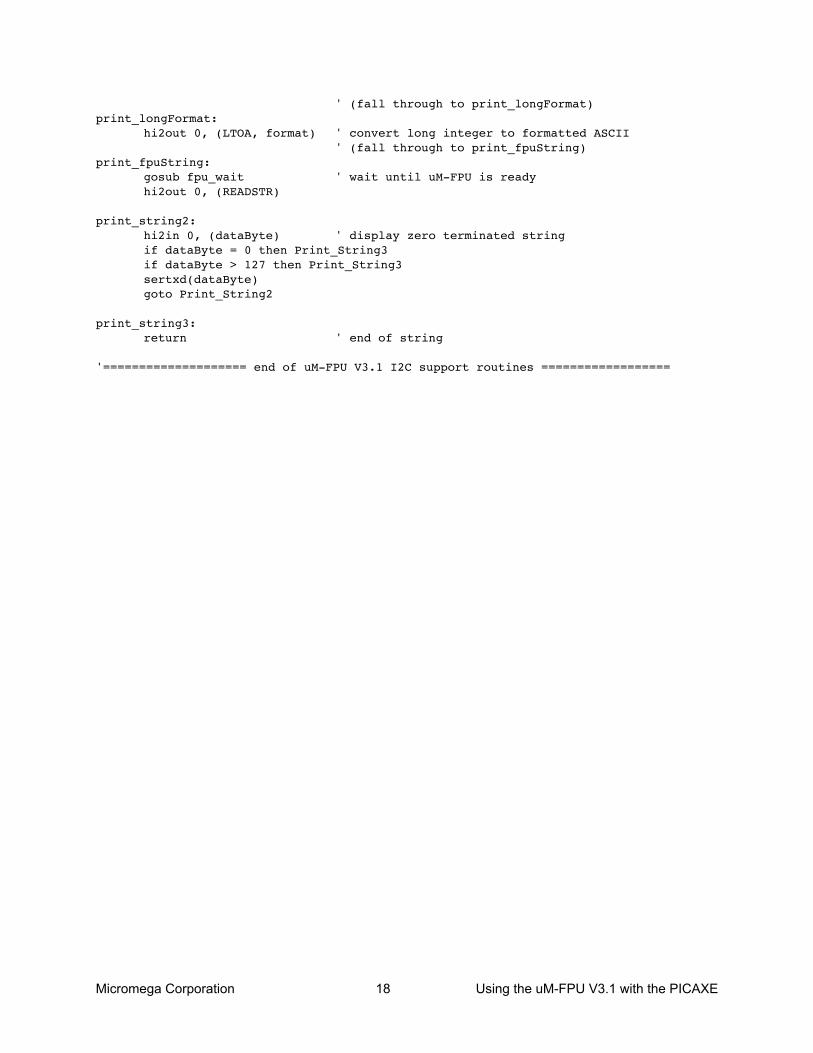
' (fall through to print_longFormat)print_longFormat:
hi2out 0, (LTOA, format) ' convert long integer to formatted ASCII' (fall through to print_fpuString)
print_fpuString:gosub fpu_wait ' wait until uM-FPU is readyhi2out 0, (READSTR)
print_string2:hi2in 0, (dataByte) ' display zero terminated stringif dataByte = 0 then Print_String3if dataByte > 127 then Print_String3sertxd(dataByte)goto Print_String2
print_string3:return ' end of string
'==================== end of uM-FPU V3.1 I2C support routines ==================
Micromega Corporation 19 Using the uM-FPU V3.1 with the PICAXE
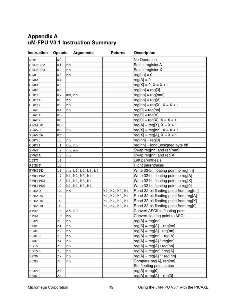
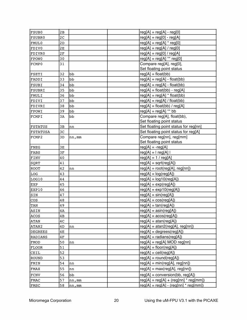
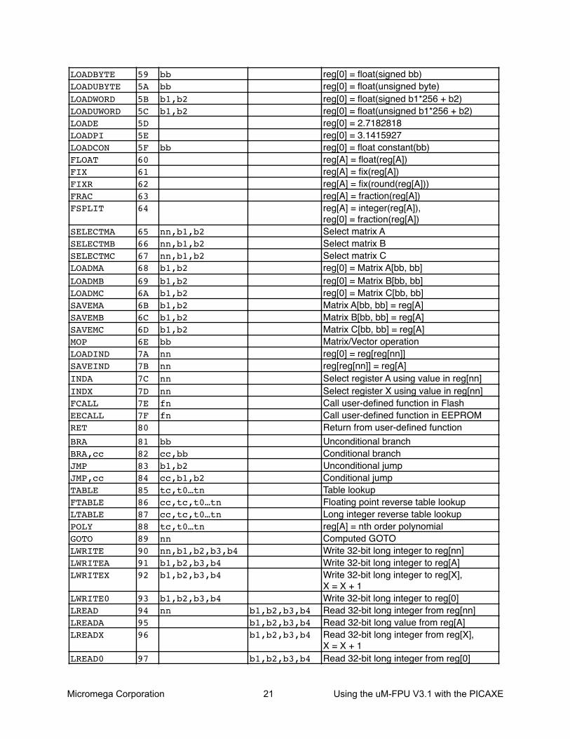
Appendix AuM-FPU V3.1 Instruction Summary
Instruction Opcode Arguments Returns DescriptionNOPSELECTASELECTXCLRCLRACLRXCLR0COPYCOPYACOPYXLOADLOADALOADXALOADXXSAVEXSAVEACOPY0COPYISWAPSWAPALEFTRIGHTFWRITEFWRITEAFWRITEXFWRITE0FREADFREADAFREADXFREAD0ATOFFTOAFSETFADDFSUBFSUBRFMULFDIVFDIVRFPOWFCMP
FSET0FADD0
000102030405060708090A0B0C0D0E0F101112131415161718191A1B1C1C1E1F202122232425262728
292A
nnnnnn
mm,nnnnnnnn
nn
nnbb,nnnn,mmnn
nn,b1,b2,b3,b4b1,b2,b3,b4b1,b2,b3,b4b1,b2,b3,b4nn
aa…00bbnnnnnnnnnnnnnnnnnn
b1,b2,b3,b4b1,b2,b3,b4b1,b2,b3,b4b1,b2,b3,b4
No OperationSelect register ASelect register Xreg[nn] = 0reg[A] = 0reg[X] = 0, X = X + 1reg[nn] = reg[0]reg[nn] = reg[mm]reg[nn] = reg[A]reg[nn] = reg[X], X = X + 1reg[0] = reg[nn]reg[0] = reg[A]reg[0] = reg[X], X = X + 1reg[A] = reg[X], X = X + 1reg[X] = reg[nn], X = X + 1reg[X] = reg[A], X = X + 1reg[nn] = reg[0]reg[nn] = long(unsigned byte bb)Swap reg[nn] and reg[mm]Swap reg[nn] and reg[A]Left parenthesisRight parenthesisWrite 32-bit floating point to reg[nn]Write 32-bit floating point to reg[A]Write 32-bit floating point to reg[X]Write 32-bit floating point to reg[0]Read 32-bit floating point from reg[nn]Read 32-bit floating point from reg[A]Read 32-bit floating point from reg[X]Read 32-bit floating point from reg[0]Convert ASCII to floating pointConvert floating point to ASCIIreg[A] = reg[nn]reg[A] = reg[A] + reg[nn]reg[A] = reg[A] - reg[nn]reg[A] = reg[nn] - reg[A]reg[A] = reg[A] * reg[nn]reg[A] = reg[A] / reg[nn]reg[A] = reg[nn] / reg[A]reg[A] = reg[A] ** reg[nn]Compare reg[A], reg[nn],Set floating point statusreg[A] = reg[0]reg[A] = reg[A] + reg[0]
Micromega Corporation 20 Using the uM-FPU V3.1 with the PICAXE
FSUB0FSUBR0FMUL0FDIV0FDIVR0FPOW0FCMP0
FSETIFADDIFSUBIFSUBRIFMULIFDIVIFDIVRIFPOWIFCMPI
FSTATUSFSTATUSAFCMP2
FNEGFABSFINVSQRTROOTLOGLOG10EXPEXP10SINCOSTANASINACOSATANATAN2DEGREESRADIANSFMODFLOORCEILROUNDFMINFMAX
FCNVFMACFMSC
2B2C2D2E2F3031
32333435363738393A
3B3C3D
3E3F404142434445464748494A4B4C4D4E4F505152535455
565758
bbbbbbbbbbbbbbbbbb
nn
nn,mm
nn
nn
nn
nnnn
bbnn,mmnn,mm
reg[A] = reg[A] - reg[0]reg[A] = reg[0] - reg[A]reg[A] = reg[A] * reg[0]reg[A] = reg[A] / reg[0]reg[A] = reg[0] / reg[A]reg[A] = reg[A] ** reg[0]Compare reg[A], reg[0],Set floating point statusreg[A] = float(bb)reg[A] = reg[A] - float(bb)reg[A] = reg[A] - float(bb)reg[A] = float(bb) - reg[A] reg[A] = reg[A] * float(bb)reg[A] = reg[A] / float(bb)reg[A] = float(bb) / reg[A] reg[A] = reg[A] ** bbCompare reg[A], float(bb),Set floating point statusSet floating point status for reg[nn]Set floating point status for reg[A]Compare reg[nn], reg[mm]Set floating point statusreg[A] = -reg[A]reg[A] = | reg[A] |reg[A] = 1 / reg[A]reg[A] = sqrt(reg[A])reg[A] = root(reg[A], reg[nn])reg[A] = log(reg[A])reg[A] = log10(reg[A])reg[A] = exp(reg[A])reg[A] = exp10(reg[A])reg[A] = sin(reg[A])reg[A] = cos(reg[A])reg[A] = tan(reg[A])reg[A] = asin(reg[A])reg[A] = acos(reg[A])reg[A] = atan(reg[A])reg[A] = atan2(reg[A], reg[nn])reg[A] = degrees(reg[A])reg[A] = radians(reg[A])reg[A] = reg[A] MOD reg[nn]reg[A] = floor(reg[A])reg[A] = ceil(reg[A])reg[A] = round(reg[A])reg[A] = min(reg[A], reg[nn])reg[A] = max(reg[A], reg[nn])reg[A] = conversion(bb, reg[A])reg[A] = reg[A] + (reg[nn] * reg[mm])reg[A] = reg[A] - (reg[nn] * reg[mm])
Micromega Corporation 21 Using the uM-FPU V3.1 with the PICAXE
LOADBYTELOADUBYTELOADWORDLOADUWORDLOADELOADPILOADCONFLOATFIXFIXRFRACFSPLIT
SELECTMASELECTMBSELECTMCLOADMALOADMBLOADMCSAVEMASAVEMBSAVEMCMOPLOADINDSAVEINDINDAINDXFCALLEECALLRET
BRABRA,ccJMPJMP,ccTABLEFTABLELTABLEPOLYGOTOLWRITELWRITEALWRITEX
LWRITE0LREADLREADALREADX
LREAD0
595A5B5C5D5E5F6061626364
65666768696A6B6C6D6E7A7B7C7D7E7F80
818283848586878889909192
93949596
97
bbbbb1,b2b1,b2
bb
nn,b1,b2nn,b1,b2nn,b1,b2b1,b2b1,b2b1,b2b1,b2b1,b2b1,b2bbnnnnnnnnfnfn
bbcc,bbb1,b2cc,b1,b2tc,t0…tncc,tc,t0…tncc,tc,t0…tntc,t0…tnnnnn,b1,b2,b3,b4b1,b2,b3,b4b1,b2,b3,b4
b1,b2,b3,b4nn b1,b2,b3,b4
b1,b2,b3,b4b1,b2,b3,b4
b1,b2,b3,b4
reg[0] = float(signed bb)reg[0] = float(unsigned byte)reg[0] = float(signed b1*256 + b2)reg[0] = float(unsigned b1*256 + b2)reg[0] = 2.7182818reg[0] = 3.1415927reg[0] = float constant(bb)reg[A] = float(reg[A])reg[A] = fix(reg[A])reg[A] = fix(round(reg[A]))reg[A] = fraction(reg[A])reg[A] = integer(reg[A]),reg[0] = fraction(reg[A])Select matrix ASelect matrix BSelect matrix Creg[0] = Matrix A[bb, bb]reg[0] = Matrix B[bb, bb]reg[0] = Matrix C[bb, bb]Matrix A[bb, bb] = reg[A]Matrix B[bb, bb] = reg[A]Matrix C[bb, bb] = reg[A]Matrix/Vector operationreg[0] = reg[reg[nn]]reg[reg[nn]] = reg[A]Select register A using value in reg[nn]Select register X using value in reg[nn]Call user-defined function in FlashCall user-defined function in EEPROMReturn from user-defined functionUnconditional branchConditional branchUnconditional jumpConditional jumpTable lookupFloating point reverse table lookupLong integer reverse table lookupreg[A] = nth order polynomialComputed GOTOWrite 32-bit long integer to reg[nn]Write 32-bit long integer to reg[A]Write 32-bit long integer to reg[X],X = X + 1Write 32-bit long integer to reg[0]Read 32-bit long integer from reg[nn]Read 32-bit long value from reg[A]Read 32-bit long integer from reg[X],X = X + 1Read 32-bit long integer from reg[0]

Micromega Corporation 22 Using the uM-FPU V3.1 with the PICAXE
LREADBYTELREADWORDATOLLTOALSETLADDLSUBLMULLDIV
LCMP
LUDIV
LUCMP
LTST
LSET0LADD0LSUB0LMUL0LDIV0
LCMP0
LUDIV0
LUCMP0
LTST0
LSETILADDILSUBILMULILDIVI
LCMPI
LUDIVI
LUCMPI
LTSTI
LSTATUSLSTATUSALCMP2
98999A9B9C9D9E9FA0
A1
A2
A3
A4
A5A6A7A8A9
AA
AB
AC
AD
AEAFB0B1B2
B3
B4
B5
B6
B7B8B9
aa…00bbnnnnnnnnnn
nn
nn
nn
nn
bbbbbbbbbb
bb
bb
bb
bb
nn
nn,mm
bbb1,b2
Read lower 8 bits of reg[A]Read lower 16 bits reg[A]Convert ASCII to long integerConvert long integer to ASCIIreg[A] = reg[nn]reg[A] = reg[A] + reg[nn]reg[A] = reg[A] - reg[nn]reg[A] = reg[A] * reg[nn]reg[A] = reg[A] / reg[nn]reg[0] = remainderSigned compare reg[A] and reg[nn],Set long integer statusreg[A] = reg[A] / reg[nn]reg[0] = remainderUnsigned compare reg[A] and reg[nn],Set long integer statusTest reg[A] AND reg[nn],Set long integer statusreg[A] = reg[0]reg[A] = reg[A] + reg[0]reg[A] = reg[A] - reg[0]reg[A] = reg[A] * reg[0]reg[A] = reg[A] / reg[0]reg[0] = remainderSigned compare reg[A] and reg[0],set long integer statusreg[A] = reg[A] / reg[0]reg[0] = remainderUnsigned compare reg[A] and reg[0],Set long integer statusTest reg[A] AND reg[0],Set long integer status reg[A] = long(bb)reg[A] = reg[A] + long(bb)reg[A] = reg[A] - long(bb)reg[A] = reg[A] * long(bb)reg[A] = reg[A] / long(bb)reg[0] = remainderSigned compare reg[A] - long(bb),Set long integer statusreg[A] = reg[A] / unsigned long(bb)reg[0] = remainderUnsigned compare reg[A] and long(bb),Set long integer statusTest reg[A] AND long(bb),Set long integer statusSet long integer status for reg[nn]Set long integer status for reg[A]Signed long compare reg[nn], reg[mm]Set long integer status
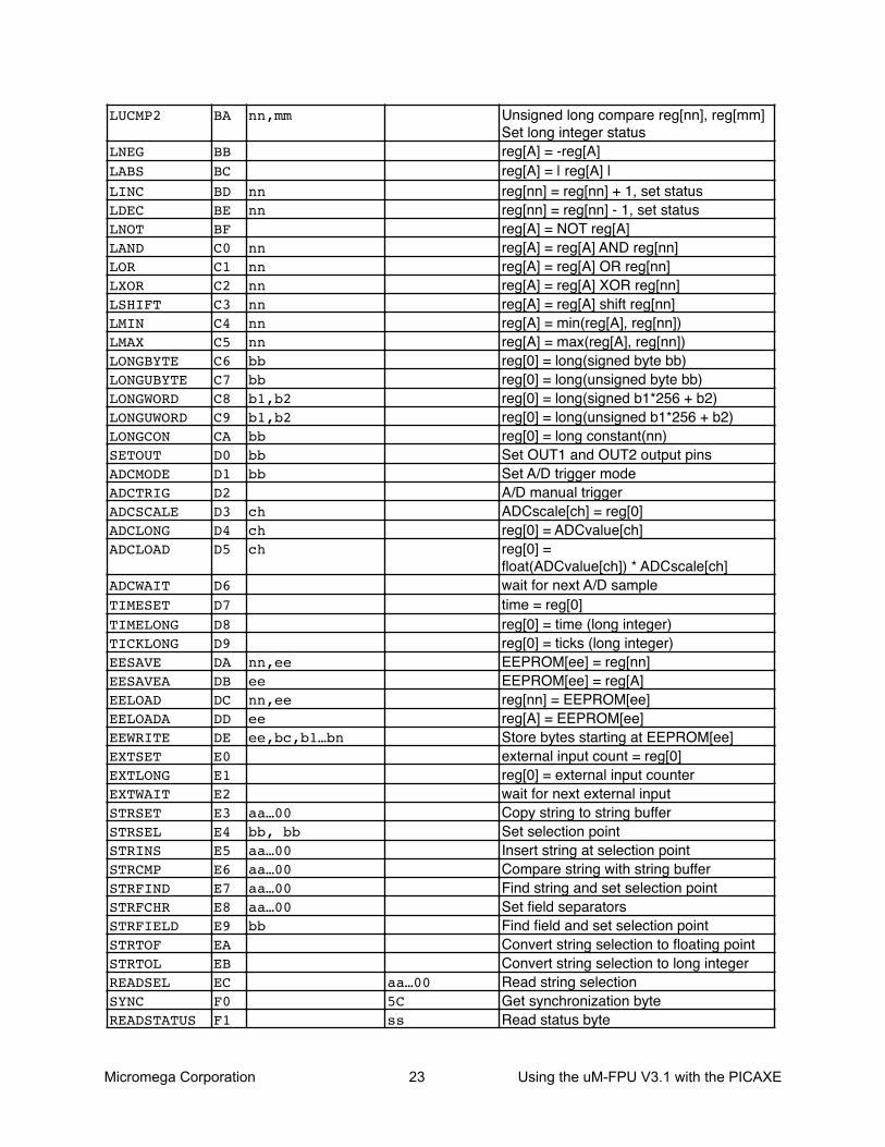
Micromega Corporation 23 Using the uM-FPU V3.1 with the PICAXE
LUCMP2
LNEGLABSLINCLDECLNOTLANDLORLXORLSHIFTLMINLMAXLONGBYTELONGUBYTELONGWORDLONGUWORDLONGCONSETOUTADCMODEADCTRIGADCSCALEADCLONGADCLOAD
ADCWAITTIMESETTIMELONGTICKLONGEESAVEEESAVEAEELOADEELOADAEEWRITEEXTSETEXTLONGEXTWAITSTRSETSTRSELSTRINSSTRCMPSTRFINDSTRFCHRSTRFIELDSTRTOFSTRTOLREADSELSYNCREADSTATUS
BA
BBBCBDBEBFC0C1C2C3C4C5C6C7C8C9CAD0D1D2D3D4D5
D6D7D8D9DADBDCDDDEE0E1E2E3E4E5E6E7E8E9EAEBECF0F1
nn,mm
nnnn
nnnnnnnnnnnnbbbbb1,b2b1,b2bbbbbb
chchch
nn,eeeenn,eeeeee,bc,b1…bn
aa…00bb, bbaa…00aa…00aa…00aa…00bb
aa…005Css
Unsigned long compare reg[nn], reg[mm]Set long integer statusreg[A] = -reg[A]reg[A] = | reg[A] |reg[nn] = reg[nn] + 1, set statusreg[nn] = reg[nn] - 1, set statusreg[A] = NOT reg[A]reg[A] = reg[A] AND reg[nn]reg[A] = reg[A] OR reg[nn]reg[A] = reg[A] XOR reg[nn]reg[A] = reg[A] shift reg[nn]reg[A] = min(reg[A], reg[nn])reg[A] = max(reg[A], reg[nn])reg[0] = long(signed byte bb)reg[0] = long(unsigned byte bb)reg[0] = long(signed b1*256 + b2)reg[0] = long(unsigned b1*256 + b2)reg[0] = long constant(nn)Set OUT1 and OUT2 output pinsSet A/D trigger modeA/D manual triggerADCscale[ch] = reg[0]reg[0] = ADCvalue[ch]reg[0] =float(ADCvalue[ch]) * ADCscale[ch]wait for next A/D sampletime = reg[0]reg[0] = time (long integer)reg[0] = ticks (long integer)EEPROM[ee] = reg[nn]EEPROM[ee] = reg[A]reg[nn] = EEPROM[ee]reg[A] = EEPROM[ee]Store bytes starting at EEPROM[ee]external input count = reg[0]reg[0] = external input counterwait for next external inputCopy string to string bufferSet selection pointInsert string at selection pointCompare string with string bufferFind string and set selection pointSet field separatorsFind field and set selection pointConvert string selection to floating pointConvert string selection to long integerRead string selectionGet synchronization byteRead status byte
Micromega Corporation 24 Using the uM-FPU V3.1 with the PICAXE
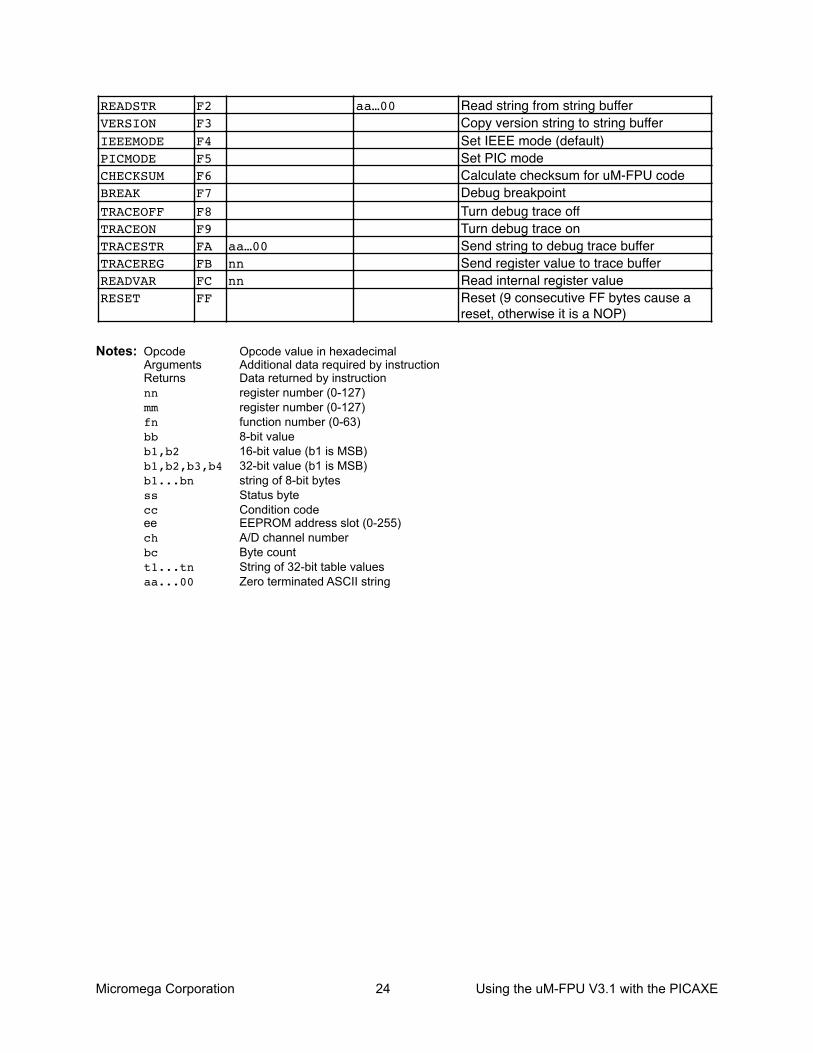
Notes: Opcode Opcode value in hexadecimalArguments Additional data required by instructionReturns Data returned by instructionnn register number (0-127)mm register number (0-127)fn function number (0-63)bb 8-bit valueb1,b2 16-bit value (b1 is MSB)b1,b2,b3,b4 32-bit value (b1 is MSB)b1...bn string of 8-bit bytesss Status bytecc Condition codeee EEPROM address slot (0-255)ch A/D channel numberbc Byte countt1...tn String of 32-bit table valuesaa...00 Zero terminated ASCII string
READSTRVERSIONIEEEMODEPICMODECHECKSUMBREAKTRACEOFFTRACEONTRACESTRTRACEREGREADVARRESET
F2F3F4F5F6F7F8F9FAFBFCFF
aa…00nnnn
aa…00 Read string from string bufferCopy version string to string bufferSet IEEE mode (default)Set PIC modeCalculate checksum for uM-FPU codeDebug breakpointTurn debug trace offTurn debug trace onSend string to debug trace bufferSend register value to trace bufferRead internal register valueReset (9 consecutive FF bytes cause a reset, otherwise it is a NOP)
Micromega Corporation 25 Using the uM-FPU V3.1 with the PICAXE
Appendix B
Floating Point Numbers
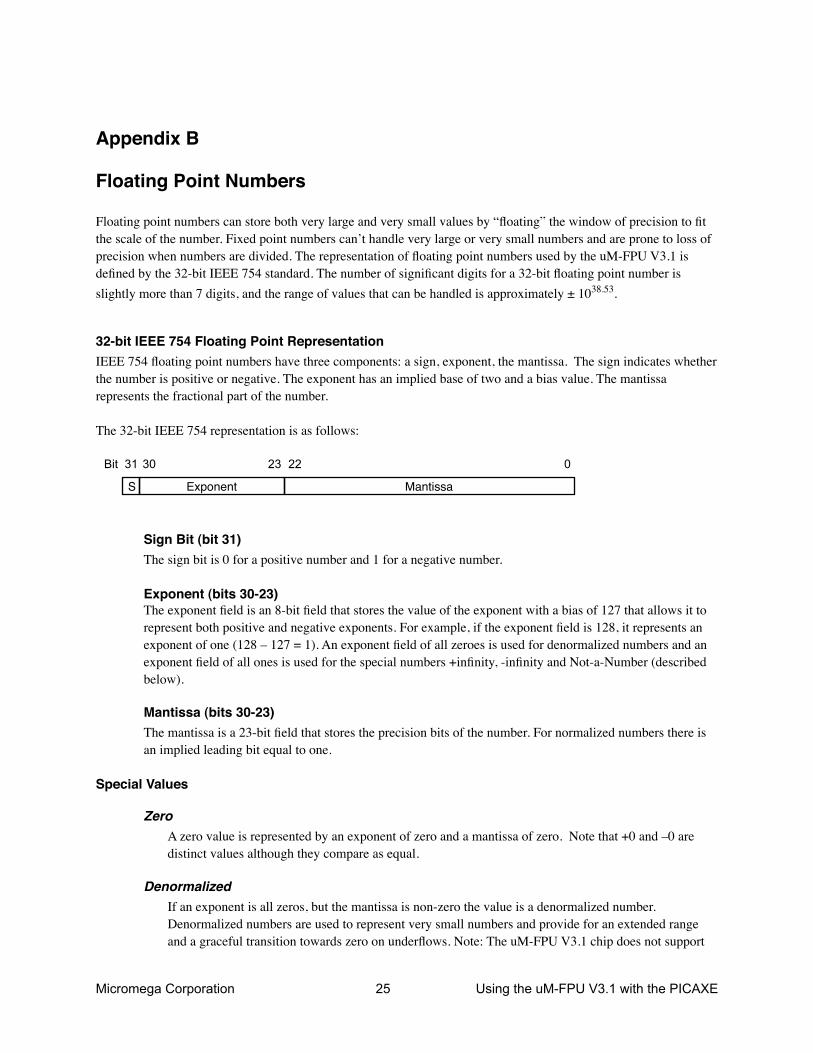
Floating point numbers can store both very large and very small values by “floating” the window of precision to fit the scale of the number. Fixed point numbers can’t handle very large or very small numbers and are prone to loss of precision when numbers are divided. The representation of floating point numbers used by the uM-FPU V3.1 is defined by the 32-bit IEEE 754 standard. The number of significant digits for a 32-bit floating point number is slightly more than 7 digits, and the range of values that can be handled is approximately ± 1038.53.
32-bit IEEE 754 Floating Point RepresentationIEEE 754 floating point numbers have three components: a sign, exponent, the mantissa. The sign indicates whether the number is positive or negative. The exponent has an implied base of two and a bias value. The mantissa represents the fractional part of the number.
The 32-bit IEEE 754 representation is as follows:
Exponent MantissaS
31 30 23 22 0Bit
Sign Bit (bit 31)The sign bit is 0 for a positive number and 1 for a negative number.
Exponent (bits 30-23)The exponent field is an 8-bit field that stores the value of the exponent with a bias of 127 that allows it to represent both positive and negative exponents. For example, if the exponent field is 128, it represents an exponent of one (128 – 127 = 1). An exponent field of all zeroes is used for denormalized numbers and an exponent field of all ones is used for the special numbers +infinity, -infinity and Not-a-Number (described below).
Mantissa (bits 30-23)The mantissa is a 23-bit field that stores the precision bits of the number. For normalized numbers there is an implied leading bit equal to one.
Special Values
ZeroA zero value is represented by an exponent of zero and a mantissa of zero. Note that +0 and –0 are distinct values although they compare as equal.
DenormalizedIf an exponent is all zeros, but the mantissa is non-zero the value is a denormalized number. Denormalized numbers are used to represent very small numbers and provide for an extended range and a graceful transition towards zero on underflows. Note: The uM-FPU V3.1 chip does not support

Micromega Corporation 26 Using the uM-FPU V3.1 with the PICAXE
operations using denormalized numbers.
InfinityThe values +infinity and –infinity are denoted with an exponent of all ones and a fraction of all zeroes. The sign bit distinguishes between +infinity and –infinity. This allows operations to continue past an overflow. A nonzero number divided by zero will result in an infinity value.
Not A Number (NaN)The value NaN is used to represent a value that does not represent a real number. An operation such as zero divided by zero will result in a value of NaN. The NaN value will flow through any mathematical operation. Note: The FPU initializes all of its registers to NaN at reset, therefore any operation that uses a register that has not been previously set with a value will produce a result of NaN.
Some examples of 32-bit IEEE 754 floating point values displayed as four byte values are as follows:
$00, $00, $00, $00 '0.0$3D, $CC, $CC, $CD '0.1 $3F, $00, $00, $00 '0.5$3F, $40, $00, $00 '0.75$3F, $7F, $F9, $72 '0.9999$3F, $80, $00, $00 '1.0$40, $00, $00, $00 '2.0$40, $2D, $F8, $54 '2.7182818 (e)$40, $49, $0F, $DB '3.1415927 (pi)$41, $20, $00, $00 '10.0$42, $C8, $00, $00 '100.0$44, $7A, $00, $00 '1000.0$44, $9A, $52, $2B '1234.5678$49, $74, $24, $00 '1000000.0$80, $00, $00, $00 '-0.0$BF, $80, $00, $00 '-1.0$C1, $20, $00, $00 '-10.0$C2, $C8, $00, $00 '-100.0$7F, $C0, $00, $00 'NaN (Not-a-Number)$7F, $80, $00, $00 '+inf$FF, $80, $00, $00 '-inf