Using Thermal Integrity Profiling (TIP) in Challenging ...
2
With increasing global acceptance of Thermal Integrity Profiling (TIP), the test method continues to be employed in more and more challenging environments. This article looks at a drilled shaft project located in Montana with varying ground conditions, and how TIP was successfully employed to provide quality assurance. Thermal Integrity Profiling is a non-destructive integrity test method used for evaluating the post-construction quality of cast-in-place foundations. This method uses the temperature measurements, or hydration energy, from the curing cement to assess shaft shape and integrity, concrete quality, and the relative alignment of the reinforcing cage. The temperature measurements are obtained using embedded Thermal Wire® cables attached longitudinally to the reinforcing cage of the drilled shaft, or attached to a center bar for smaller diameter auger cast-in-place (ACIP) piles. Elevated concrete or grout temperatures, after placement and uniform thermal profile, are due to the rate of energy production being many times greater than the surrounding soil’s ability to dissipate the heat. In general, reductions in temperature correlate to reductions in the effective radius or the presence of lower strength concrete/grout. Increases in temperature correlate to increases in cover or areas of increased cross-section. For a perfectly cylindrical shaft with boundary conditions held constant with depth (e.g., a shaft entirely embedded below grade), the heat dissipation is only radial, and therefore the temperature is uniform except at the ends where temperature roll-offs are observed due to additional axial heat exchanges. Adjustments are applied to account for these end conditions as part of the standard TIP analysis and can be automatically included using the TIP-Reporter (TIP-R) software. Recently, TIP testing was per- formed for integrity evalua- tion of drilled shafts installed on a Montana Department of Transportation (MDT) bridge project in Yellowstone County, Montana. The project consisted of 10 piers and a total of 24 drilled shafts. Most of the drilled shafts were 10 ft. (3m) in diameter and had lengths from 21 feet (6.4m) to 40 feet (12m). The testing objective was to assess the integrity of the drilled shafts. TIP testing was completed in one shaft per pier with 10 Thermal Wire® cables attached along the length of each reinforcing cage prior to cage and concrete placement. Figure 1 represents the typical unadjusted temperature data (degrees Fahrenheit) versus depth (feet) for most shafts on this project. Shafts in all piers (except pier 8) were analyzed with only standard top and bottom roll-off adjustments. Pier 8 contained the only drilled shafts placed within the Yellowstone River’s flowing water. These shafts were 10 feet (3m) in diameter and 40.3 feet (12.3 m) in length, with the bottom 20 feet (6.1 m) in rock socket. Because of the extra cooling effect caused by the flowing river water, between depths 7 to 13 feet (2.1 to 4 m) below the top of the shafts in pier 8, a mid- shaft adjustment was required to account for the extra loss of heat. When sections of the shaft extend above grade, such as in air or cased through water, changes in the thermal profile are observed due to changes in diffusivity. These observed changes are caused by boundary conditions, not geometric changes, and must be addressed to properly assess shaft integrity. Mid-shaft adjustments are applied at each boundary transition based on the same theory and equations used to account for the end effects on the temperature profile. Figure 2. represents the mea- sured temperature (degree Fahrenheit) versus depth (feet) graph specifically for Pier 8. As expected, a reduction in temp- erature was observed in the regions both above the water and where the flowing river water condition was reported. Prior to generating the effective radius versus depth plots shown in Figure 3, mid-shaft adjustments were performed at the transitions from the air/water interface and the water/soil interface. The resulting thermal profile after applying the top and bottom of shaft roll-off adjustments, along with the mid-shaft adjustments at the top of water and mudline elevations, is presented in Figure 4 (see page 2). Complete and detailed installation logs for all 10 piers on MDT’s Yellowstone River bridge project were provided by Michels Corporation, allowing for an efficient and accurate analysis and DID YOU KNOW? Newsletter No. 97 - March, 2021 Wave Equation Analysis was first introduced in the mid-1960s and continues to be used worldwide. Using Thermal Integrity Profiling (TIP) in Challenging Environments By Danny Belardo, GRL Engineers, Inc. Figure 1. Typical Temperature vs. Depth profile for most shafts on the MDT Yel- lowstone River Bridge Project. Figure 2. Temperature vs. Depth profile with reduction in temperature observed where the shaft is cased through water. Figure 3. Effective radius plot creat- ed after top and bottom roll off and mid shaft adjustments are made.
Transcript of Using Thermal Integrity Profiling (TIP) in Challenging ...
With increasing global acceptance of Thermal Integrity Profiling (TIP), the test method continues to be employed in more and more challenging environments. This article looks at a drilled shaft project located in Montana with varying ground conditions, and how TIP was successfully employed to provide quality assurance.
Thermal Integrity Profiling is a non-destructive integrity test method used for evaluating the post-construction quality of cast-in-place foundations. This method uses the temperature measurements, or hydration energy, from the curing cement to assess shaft shape and integrity, concrete quality, and the relative alignment of the reinforcing cage. The temperature measurements are obtained using embedded Thermal Wire® cables attached longitudinally to the reinforcing cage of the drilled shaft, or attached to a center bar for smaller diameter auger cast-in-place (ACIP) piles.
Elevated concrete or grout temperatures, after placement and uniform thermal profile, are due to the rate of energy production being many times greater than the surrounding soil’s ability to dissipate the heat. In general, reductions in temperature correlate to reductions in the effective radius or the presence of lower strength concrete/grout. Increases in temperature correlate to increases in cover or areas of increased cross-section.
For a perfectly cylindrical shaft with boundary conditions held constant with depth (e.g., a shaft entirely embedded below grade), the heat dissipation is only radial, and therefore the temperature is uniform except at the ends where temperature roll-offs are observed due to additional axial heat exchanges. Adjustments are applied to account for these end conditions as part of the standard TIP analysis and can be automatically included using the TIP-Reporter (TIP-R) software.
Recently, TIP testing was per-formed for integrity evalua-tion of drilled shafts installed on a Montana Department of Transportation (MDT) bridge project in Yellowstone County, Montana. The project consisted of 10 piers and a total of 24 drilled shafts. Most of the drilled shafts were 10 ft. (3m) in diameter and had lengths from 21 feet (6.4m) to 40 feet (12m). The testing objective was to assess the integrity of the drilled shafts. TIP testing was completed in one shaft per pier with 10 Thermal Wire® cables attached along the length of each reinforcing cage prior to cage and concrete placement.
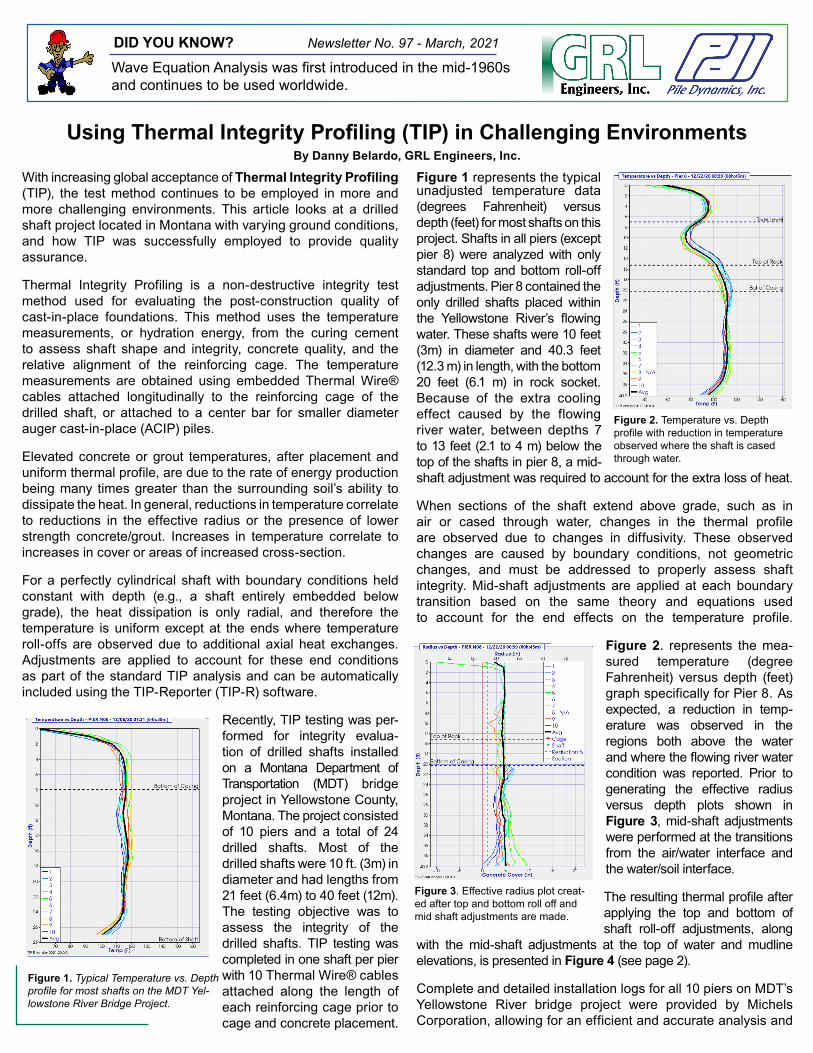
Figure 1 represents the typical unadjusted temperature data (degrees Fahrenheit) versus depth (feet) for most shafts on this project. Shafts in all piers (except pier 8) were analyzed with only standard top and bottom roll-off adjustments. Pier 8 contained the only drilled shafts placed within the Yellowstone River’s flowing water. These shafts were 10 feet (3m) in diameter and 40.3 feet (12.3 m) in length, with the bottom 20 feet (6.1 m) in rock socket. Because of the extra cooling effect caused by the flowing river water, between depths 7 to 13 feet (2.1 to 4 m) below the top of the shafts in pier 8, a mid-shaft adjustment was required to account for the extra loss of heat.
When sections of the shaft extend above grade, such as in air or cased through water, changes in the thermal profile are observed due to changes in diffusivity. These observed changes are caused by boundary conditions, not geometric changes, and must be addressed to properly assess shaft integrity. Mid-shaft adjustments are applied at each boundary transition based on the same theory and equations used to account for the end effects on the temperature profile.
Figure 2. represents the mea-sured temperature (degree Fahrenheit) versus depth (feet) graph specifically for Pier 8. As expected, a reduction in temp-erature was observed in the regions both above the water and where the flowing river water condition was reported. Prior to generating the effective radius versus depth plots shown in Figure 3, mid-shaft adjustments were performed at the transitions from the air/water interface and the water/soil interface.
The resulting thermal profile after applying the top and bottom of shaft roll-off adjustments, along
with the mid-shaft adjustments at the top of water and mudline elevations, is presented in Figure 4 (see page 2).
Complete and detailed installation logs for all 10 piers on MDT’s Yellowstone River bridge project were provided by Michels Corporation, allowing for an efficient and accurate analysis and
DID YOU KNOW? Newsletter No. 97 - March, 2021
Wave Equation Analysis was first introduced in the mid-1960s and continues to be used worldwide.
Using Thermal Integrity Profiling (TIP) in Challenging EnvironmentsBy Danny Belardo, GRL Engineers, Inc.
Figure 1. Typical Temperature vs. Depth profile for most shafts on the MDT Yel-lowstone River Bridge Project.
Figure 2. Temperature vs. Depth profile with reduction in temperature observed where the shaft is cased through water.
Figure 3. Effective radius plot creat-ed after top and bottom roll off and mid shaft adjustments are made.

Dr. Frank Rausche Named PDCA’s E.A.L. Smith Award Lecturer
PDCA has selected Frank Rausche, Ph.D., P.E., D.GE, president emeritus of GRL Engineers, Inc. and senior consultant at Pile Dynamics, Inc., as the 2021 presenter for The E.A.L. Smith Award Lecture, presented triennially during International Foundations Conference & Equipment Expo (IFCEE) and is given to an individual who has impacted the driven pile industry.
Dr. Rausche has been involved in the research and development of dynamic testing and analysis methods since the mid-1960s, developing the original CAPWAP® program in 1969 and its continued improvements. He devised the Case Method Capacity and Integrity Formulas and was co-developer of the Pile Driving Analyzer®, cementing dynamic pile testing as a routine practice in the industry. He also served as the co-principal investigator in the development of the WEAP wave equation program for the Federal Highways Administration in 1976 and was principal investigator in 1976, its subsequent 1981 update, and starting in the 1980s GRLWEAP for personal computers. He then developed GRLWEAP for personal computers in the 1980s.
Dr. Rausche will receive the award and deliver his lecture at IFCEE 2021, held in Dallas, Texas, May 10 to 14.
DFI Goble Rausche Likins Scholarship Fund
The Goble Rausche Likins Scholarship Fund was established in October 2020, via the Deep Foundation Institute’s Educa-tional Trust, with a generous donation from GRL Engineers, Inc. (GRL) and Pile Dynamics, Inc. (PDI).
The fund honors George G. Goble, Frank Rausche and Gar-land E. Likins, the founders of GRL Engineers, Inc. (GRL) and Pile Dynamics, Inc. (PDI), and provides At-Large Schol-arships to full-time undergraduate or graduate civil engineer-ing, electrical engineering and computer science students attending any accredited college or university in the United States, and who demonstrate prior employment, co-op or in-tern experience with a civil engineering application.
Donations to the Goble Rausche Likins Scholarship Fund can be made online at www.dfitrust.org. The DFI Educational Trust has awarded more than $1,200,000 in scholarships to more than 300 students in fields of study related to the deep foundations industry.
Follow Us On Social Media
GRL Engineers, Inc. [email protected]
California • Colorado • Florida •Georgia • Illinois • Louisiana • North Carolina • Ohio • Pennsylvania •Texas • Washington
Pile Dynamics, [email protected]
30725 Aurora Rd, Cleveland, OH 44139
Upcoming Events
March 23-26 Conference: Piling2020 - London, England
April 16 Conference: Rocky Mountain GeoConference - Westminster, COApril 16 Webinar: PDA Discussion Topics April 19, 20, 22 Webinar Series: GRLWEAP14 - Topic Specific Discussions April 19th Session at 11:00am EDT Registration April 20th Session at 9:00pm EDT Registration April 22nd Session at 9:00am EDT RegistrationApril 21-23 Conference: Design Build in Aviation & Transportation
May 7 Webinar: Thermal Integrity Profiler (TIP) Discussion TopicsMay 10-14 Conference: IFCEE 2021 - Dallas, TX Visit Us at Booth 1226May 25 WEBINAR: SPT Hammer Energy Measurements - EnglishMay 27 WEBINAR: SPT Hammer Energy Measurements - Spanish
June 2-4 Conference: SEI Structures June 7-11 Conference: International BridgeJune 22-24 Conference: Southwest Geotechnical Engineering June 23-25 Conference: DFI SuperPile 21 - Philadelphia, PA Visit us at Booth 115June 24-25 Conference: 35th Christian Veder Kolliquium - Messe Graz, Austria
Figure 4. Temperature vs. Depth profile with top and bottom roll-off adjustments applied along with mid-shaft adjustments applied at the top of water and mudline.
reporting process. Well documented installation logs provide the key details required for the TIP consultant to accurately address boundary changes and conditions encountered during excavation. These details should include, at a minimum, elevations for the top of concrete, water level, mudline, bottom of casings, bottom of TIP instrumentation, bottom of shaft, and any locations where flowing water was encountered during excavation. When shafts are permanently cased through a body of water, it is recommended to drop a weighted tape outside the casing to document the elevation of the mudline which may have been altered due to the casing installation.
To date, TIP has been successfully implemented on many drilled shafts/bored piles, ACIP/CFA piles, micro piles, soil nails, jet grout columns, concrete filled slurry walls, diaphragm walls, barrettes, and controlled modulus columns projects around the world. TIP-R software allows the test engineer to easily perform analysis for many applications with varying environmental conditions. With much of the TIP data now being transmitted from the foundation to the Cloud, TIP results are available immediately upon casting, and analysis are typically completed within 48 hours of casting, with no site visits required by the test engineer, saving project time and cost. To learn more about Thermal Integrity Profiling or QA testing of drilled shafts, contact [email protected] or visit pile.com.


![Data Profiling Guide - start [Gerardnico] · PDF fileData Profiling Guide. Informatica PowerCenter Data Profiling Guide ... available at http:](https://static.fdocuments.us/doc/165x107/5aa4fb3a7f8b9ab4788c93d6/data-profiling-guide-start-gerardnico-profiling-guide-informatica-powercenter.jpg)