Using the TPS92010EVM-631, A 230-VAC, TRIAC Dimmable 6-W
16
Using the TPS92010EVM-631 User' s Guide Literature Number: SLUU430C July 2010 – Revised May 2011
Transcript of Using the TPS92010EVM-631, A 230-VAC, TRIAC Dimmable 6-W

Using the TPS92010EVM-631
User's Guide
Literature Number: SLUU430C
July 2010–Revised May 2011

User's GuideSLUU430C–July 2010–Revised May 2011
A 230-VAC TRIAC Dimmable 6-W LED Driver
1 Introduction
The TPS92010EVM-631 is a TRIAC dimmable LED driver. It can provide 0.325-A constant current to fouror five high-brightness LED’s. The EVM includes a five-LED load. It is powered from the mains which israted at 185 VRMS to 265 VRMS. The output current can be modified for constant levels from 0.2 A to 0.7 A.
2 Description
This EVM uses the TPS92010 high-efficiency offline LED lighting driver controller. The power topology is aquasi resonant mode flyback. This makes for a cost competitive solution. This TPS92010 EVMimplements a constant current, high-efficiency, low-ripple AC-DC LED lighting driver
Current sensing is done directly via a resistor and op-amp. This in turn drives an opto-coupler which setsthe PWM pulses via the TPS92010 to control the output current at a constant level. The design alsoincorporates a circuit to ensure compatibility with a large number of commonly available TRIAC baseddimmers. This circuit monitors the line voltage for TRIAC operation. Then the TRIAC is operating the linevoltage is chopped. This information is used by the circuit to reduce the constant output current level thusdimming the LED’s. It also applies a current path at the input to ensure the TRIAC triggers correctly.
2.1 Typical Applications• Household Light Bulb Replacement
2.2 Features• TRIAC Compatible Dimming• Low Cost Line Powered LED Driver Solution• Includes Five HB-LED’s as a Sample Load• Allows Easy Use of Users Own LED Load• Test Points for LED Voltage and Current• Accurate Current Sensing to Maintain Constant Current to LED’s• Modifiable Output Current from 0.2 A to 0.7 A, 0.325 A is Default
3 Electrical Performance Specifications
Table 1. Electrical Performance Specifications
PARAMETER TEST CONDITIONS MIN TYP MAX UNITS
Input Characteristics
Voltage range (1) 185 265 VRMS
Maximum input current 0.53 ARMS
Output Characteristics
Output voltage, VOUT 14 17 VDC
Output load current, IOUT Input voltage = 200 VAC to 265 VAC 0.31 0.325 0.34 ADC
Systems Characteristics
Efficiency 85%(1) Input voltages below 200 VAC may result in reduced output current.
2 A 230-VAC TRIAC Dimmable 6-W LED Driver SLUU430C–July 2010–Revised May 2011Submit Documentation Feedback
Copyright © 2010–2011, Texas Instruments Incorporated

www.ti.com Schematic
4 Schematic
Figure 1. PSU Schematic
3SLUU430C–July 2010–Revised May 2011 A 230-VAC TRIAC Dimmable 6-W LED DriverSubmit Documentation Feedback
Copyright © 2010–2011, Texas Instruments Incorporated

Test Setup www.ti.com
Figure 2. LED Board Schematic
5 Test Setup
5.1 Test Equipment
Voltage Source: 185-VRMS to 265-VRMS AC source.
Multimeters: Voltmeter for up to 20 VDC and an ammeter for up to 1 A
Output Load: Load provided or LED load that sinks 0.325 ADC and has a voltage drop between 14 VDC to17 VDC
Recommended Wire Gauge: 18 AWG
4 A 230-VAC TRIAC Dimmable 6-W LED Driver SLUU430C–July 2010–Revised May 2011Submit Documentation Feedback
Copyright © 2010–2011, Texas Instruments Incorporated

www.ti.com Test Setup
5.2 Configuring the Output Current
The TPS92010EVM-631 can be configured for different output current levels. Soldering of 0402 parts isrequired to do this. Table 2 below shows the resistor values necessary for various current levels. Figure 3shows the location of these resistors on the top side of the PSU board.
Table 2. Resistor Values to Modify Output Current
MAX OUTPUT MIN OUTPUT R15 R17 R1 R42CURRENT CURRENT (Ω) (Ω) (kΩ) (kΩ)(mA) (mA)
200 10 1000 150 330 1000
225 10 1200 86 390 1000
250 10 1200 220 470 1000
275 10 1000 560 680 680
300 10 1500 220 680 680
325 (1) 10 1500 330 560 1000
350 10 1000 1000 820 1000
400 10 1800 470 1000 1000
450 10 2200 390 1500 1000
500 12 2700 220 1500 1000
600 12 3300 150 1500 1500
700 13 3900 270 2200 1500(1) 325 mA is the default setting when the EVM is shipped.
Figure 3. Resistor Locations to Modify Output Current
5SLUU430C–July 2010–Revised May 2011 A 230-VAC TRIAC Dimmable 6-W LED DriverSubmit Documentation Feedback
Copyright © 2010–2011, Texas Instruments Incorporated

185V to 265V
AC Source
A
V
ligh ing
I
TEXAS
NSTRUMENTS
+
185V to 265V
AC SourceV
Constant Voltage
Load
14Vdc - 17Vdc
- +
A
ligh ing
ITEXAS
NSTRUMENTS
+
Test Setup www.ti.com
5.3 Recommended Test Setup
Figure 4. Recommended Test Set Up Using Internal Load
Figure 5. Recommended Test Set Up Using External Load
6 A 230-VAC TRIAC Dimmable 6-W LED Driver SLUU430C–July 2010–Revised May 2011Submit Documentation Feedback
Copyright © 2010–2011, Texas Instruments Incorporated

www.ti.com Test Procedure
6 Test Procedure
CAUTION
CAUTION: High voltages exist on this EVM. Please handle with care. Do nottouch EVM when powered.
This EVM allows the user to use one of two different set ups.
1. Internal Load: The EVM provides five on-board LED’s. To use these a short or ammeter must beconnected between pins 2 and 3 of J4, see Figure 4 above
2. External Load: If the user wants to validate the EVM with their own load pins 1 and 2 of J4 should beused. Any short between pins 2 and 3 should be removed to avoid damaging the EVM. See Figure 5above.
WARNINGDo not operate the EVM without a load, see points 1 and 2 above.
6.1 Line Regulation and Efficiency Measurement Procedure1. Connect EVM per Figure 4 or Figure 5 above.2. Set AC source to 185 VRMS.3. Turn on AC source.4. Record output voltage reading from V and output current reading from A.5. Increase output voltage by 5 VRMS.6. Repeat steps 4 and 5 until you reach 265 VRMS.7. Shutdown equipment per section 6.3.
7SLUU430C–July 2010–Revised May 2011 A 230-VAC TRIAC Dimmable 6-W LED DriverSubmit Documentation Feedback
Copyright © 2010–2011, Texas Instruments Incorporated

ligh ing
TRIAC
Dimmer
185V to 265V
AC Source
Recommended Dimmers
Brand Model
Gamma Halogeen dimmer
Merten 5725
Wintop 13112
Jung 244020300
Tradim 31032
Drespa 814
Siemens 5TC8 256
Bush 2250 U
Japan Industrial Co. FD-25
Merten 5784
Gamma 243489
Test Procedure www.ti.com
6.2 Verifying Dimming Function1. Set up the EVM per Figure 4 or Figure 5.2. Add TRIAC dimmer to the input per Figure 6.3. Set AC source to 230 VRMS.4. Set TRIAC to maximum output.5. Measure output current.6. Slowly increase TRIAC dimming to minimum output.7. Observe output current reduces.
Figure 6. Test Up Using TRIAC Dimmer
6.3 Equipment Shutdown1. Turn off AC source.2. Wait several minutes before handling the EVM.
8 A 230-VAC TRIAC Dimmable 6-W LED Driver SLUU430C–July 2010–Revised May 2011Submit Documentation Feedback
Copyright © 2010–2011, Texas Instruments Incorporated

VIN
- Input Voltage - VRMS
50
60
75
100
Eff
icie
nc
y-
%
EFFICIENCY
vs
INPUT VOLTAGE
185 225 235
95
265195
65
85
55
90
80
255205
70
215 245
VIN
- Input Voltage - VAC
310
315
335
IOU
T-
Ou
tpu
tC
urre
nt
-m
A
OUTPUT CURRENT
vs
INPUT VOLTAGE
185 225 235 265195
330
325
255205
320
215 245
www.ti.com Performance Data and Typical Characteristic Curves
7 Performance Data and Typical Characteristic Curves
Figure 7 through Figure 10 present typical performance curves for TPS92010EVM-631.
7.1 Efficiency
Figure 7. Efficiency
7.2 Line Regulation
Figure 8. Line Regulation
9SLUU430C–July 2010–Revised May 2011 A 230-VAC TRIAC Dimmable 6-W LED DriverSubmit Documentation Feedback
Copyright © 2010–2011, Texas Instruments Incorporated

Phase Trigger Angle - °
0
50
250
LE
DC
urre
nt
-m
A
EFFICIENCY
vs
INPUT VOLTAGE
0 90 120
300
18015
100
250
200
16545
150
60 13530 75 105 150
200mA/div
Performance Data and Typical Characteristic Curves www.ti.com
7.3 Dimmer Performance
Figure 9. Output Current Versus Dimmer Phase Angle
7.4 Output Current Ripple
Figure 10. Output Current Ripple with Dimmer at 0% Dim, (10 µs/div.)
10 A 230-VAC TRIAC Dimmable 6-W LED Driver SLUU430C–July 2010–Revised May 2011Submit Documentation Feedback
Copyright © 2010–2011, Texas Instruments Incorporated

www.ti.com EVM Assembly Drawing and PCB layout
8 EVM Assembly Drawing and PCB layout
The following figures (Figure 11 through Figure 14) show the design of the TPS92010EVM-631 printedcircuit board.
Figure 11. PSU Top Layer Assembly Drawing (top view)
Figure 12. PSU Top Copper (top view)
11SLUU430C–July 2010–Revised May 2011 A 230-VAC TRIAC Dimmable 6-W LED DriverSubmit Documentation Feedback
Copyright © 2010–2011, Texas Instruments Incorporated

EVM Assembly Drawing and PCB layout www.ti.com
Figure 13. PSU Bottom Assembly Drawing (bottom view)
Figure 14. Bottom Copper (bottom view)
12 A 230-VAC TRIAC Dimmable 6-W LED Driver SLUU430C–July 2010–Revised May 2011Submit Documentation Feedback
Copyright © 2010–2011, Texas Instruments Incorporated
www.ti.com List of Materials
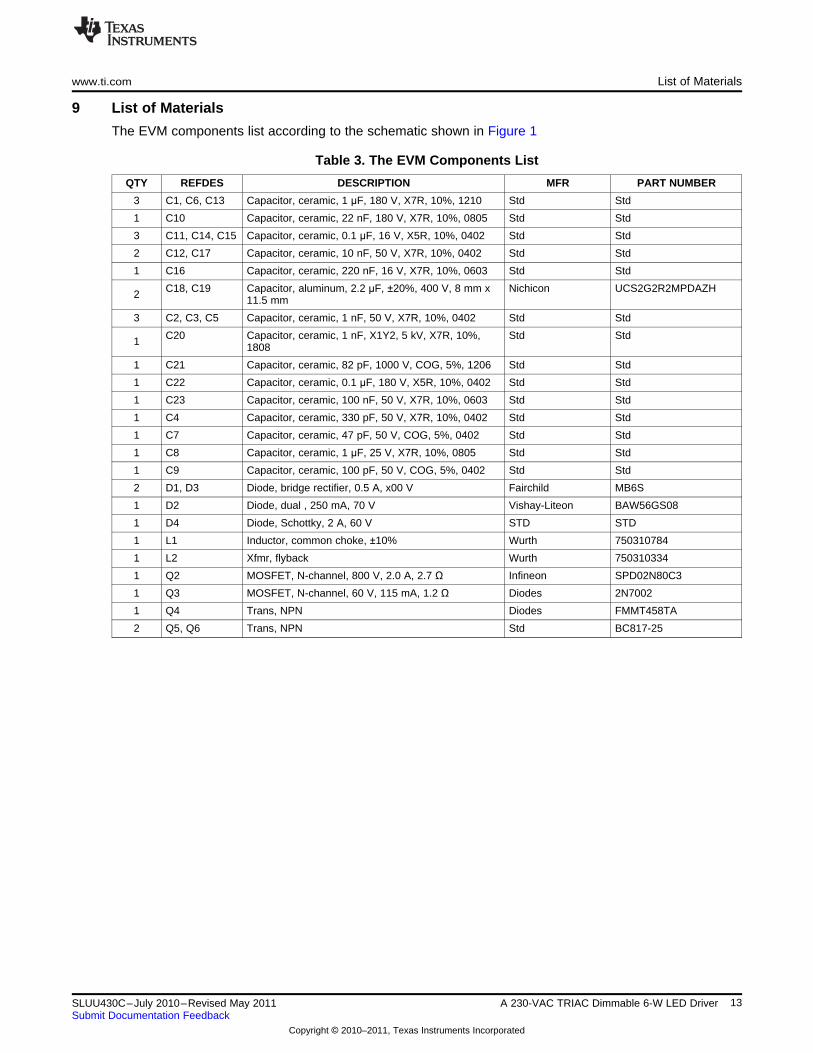
9 List of Materials
The EVM components list according to the schematic shown in Figure 1
Table 3. The EVM Components List
QTY REFDES DESCRIPTION MFR PART NUMBER
3 C1, C6, C13 Capacitor, ceramic, 1 µF, 180 V, X7R, 10%, 1210 Std Std
1 C10 Capacitor, ceramic, 22 nF, 180 V, X7R, 10%, 0805 Std Std
3 C11, C14, C15 Capacitor, ceramic, 0.1 µF, 16 V, X5R, 10%, 0402 Std Std
2 C12, C17 Capacitor, ceramic, 10 nF, 50 V, X7R, 10%, 0402 Std Std
1 C16 Capacitor, ceramic, 220 nF, 16 V, X7R, 10%, 0603 Std Std
C18, C19 Capacitor, aluminum, 2.2 µF, ±20%, 400 V, 8 mm x Nichicon UCS2G2R2MPDAZH2 11.5 mm
3 C2, C3, C5 Capacitor, ceramic, 1 nF, 50 V, X7R, 10%, 0402 Std Std
C20 Capacitor, ceramic, 1 nF, X1Y2, 5 kV, X7R, 10%, Std Std1 1808
1 C21 Capacitor, ceramic, 82 pF, 1000 V, COG, 5%, 1206 Std Std
1 C22 Capacitor, ceramic, 0.1 µF, 180 V, X5R, 10%, 0402 Std Std
1 C23 Capacitor, ceramic, 100 nF, 50 V, X7R, 10%, 0603 Std Std
1 C4 Capacitor, ceramic, 330 pF, 50 V, X7R, 10%, 0402 Std Std
1 C7 Capacitor, ceramic, 47 pF, 50 V, COG, 5%, 0402 Std Std
1 C8 Capacitor, ceramic, 1 µF, 25 V, X7R, 10%, 0805 Std Std
1 C9 Capacitor, ceramic, 100 pF, 50 V, COG, 5%, 0402 Std Std
2 D1, D3 Diode, bridge rectifier, 0.5 A, x00 V Fairchild MB6S
1 D2 Diode, dual , 250 mA, 70 V Vishay-Liteon BAW56GS08
1 D4 Diode, Schottky, 2 A, 60 V STD STD
1 L1 Inductor, common choke, ±10% Wurth 750310784
1 L2 Xfmr, flyback Wurth 750310334
1 Q2 MOSFET, N-channel, 800 V, 2.0 A, 2.7 Ω Infineon SPD02N80C3
1 Q3 MOSFET, N-channel, 60 V, 115 mA, 1.2 Ω Diodes 2N7002
1 Q4 Trans, NPN Diodes FMMT458TA
2 Q5, Q6 Trans, NPN Std BC817-25
13SLUU430C–July 2010–Revised May 2011 A 230-VAC TRIAC Dimmable 6-W LED DriverSubmit Documentation Feedback
Copyright © 2010–2011, Texas Instruments Incorporated

List of Materials www.ti.com
Table 3. The EVM Components List (continued)
QTY REFDES DESCRIPTION MFR PART NUMBER
1 R1 Resistor, chip, 560 kΩ, 1/16 W, 1%, 0402 Std Std
1 R10 Resistor, chip, 560, 1/16 W, 1%, 0402 Std Std
1 R12 Resistor, chip, 1.0 kΩ, 1/16 W, 5%, 0402 Std Std
1 R13 Resistor, chip, 33.0 kΩ, 1/16 W, 1%, 0402 Std Std
2 R14, R117 Resistor, chip, 4.70 kΩ, 1/16 W, 1%, 0402 Std Std
1 R15 Resistor, chip, 1.50 kΩ, 1/16 W, 1%, 0402 Std Std
1 R16 Resistor, chip, 4.7 Ω, 1/16 W, 5%, 0402 Std Std
1 R17 Resistor, chip, 330 Ω, 1/16 W, 1%, 0402 Std Std
1 R18 Resistor, chip, 68 kΩ, 1/16 W, 5%, 0402 Std Std
2 R2, R31 Resistor, chip, 1.0 MΩ, 1/4 W, 5%, 1206 Std Std
1 R20 Resistor, chip, 0.39 Ω, 1/10 W, 1%, 0805 Std Std
2 R21, R22 Resistor, chip, 3.90 MΩ, 1/10 W, 1%, 0805 Std Std
2 R23, R24 Resistor, chip, 10.0 MΩ, 1/4 W, 1%, 1206 Std Std
2 R25, R38 Resistor, chip, 680 kΩ, 1/16 W, 1%, 0402 Std Std
2 R26, R37 Resistor, chip, 470 kΩ, 1/16 W, 1%, 0402 Std Std
1 R27 Resistor, chip, 2.49 kΩ, 1/16 W, 1%, 0402 Std Std
1 R28 Resistor, chip, 27 Ω, 1/16 W, 5%, 0603 Std Std
1 R29 Resistor, chip, 4.70 kΩ, 1/16 W, 1%, 0603 Std Std
2 R3, R19 Resistor, chip, 8.20 kΩ, 1/16 W, 1%, 0402 Std Std
1 R30 Resistor, chip, 22.0 kΩ, 1/16 W, 1%, 0402 Std Std
2 R32, R33 Resistor, chip, 3.3 MΩ, 1/4 W, 5%, 1206 Std Std
1 R34 Resistor, chip, 100 kΩ, 1/16 W, 1%, 0603 Std Std
0 R7, R35 Resistor, chip, 1/4 W, 5%, 1206 Std Std
1 R36 Resistor, chip, 270 kΩ, 1/16 W, 1%, 0402 Std Std
1 R39 Resistor, chip, 47.0 kΩ, 1/4 W, 1%, 1206 Std Std
2 R4, R9 Resistor, chip, 2.70 kΩ, 1/16 W, 1%, 0402 Std Std
1 R40 Resistor, chip, 220 Ω, 1/16 W, 5%, 0603 Std Std
1 R41 Resistor, chip, 1.20 MΩ, 1/16 W, 1%, 0402 Std Std
1 R42 Resistor, chip, 1.50 MΩ, 1/16 W, 1%, 0402 Std Std
1 R43 Resistor, chip, 39.0 kΩ, 1/16 W, 1%, 0402 Std Std
2 R5, R11 Resistor, chip, 10.0 kΩ, 1/16 W, 1%, 0402 Std Std
1 R6 Resistor, chip, 12.0 kΩ, 1/16 W, 1%, 0402 Std Std
1 R8 Resistor, chip, 5.6 Ω, 1/16 W, 5%, 0603 Std Std
1 SIOV1 Varistor, disk, 250 V, 1 W, TA at 85°C Epcos SIOV-S05K250
1 U1 Dual Operational Amplifiers TI LM358AD
U2 Diode, Adjustable Shunt Regulator, 2.49 V to 36 V, TI TL431A1 20 mA,
1 U3 High Isolation Voltage Photocoupler CEL PS2801C-1-A
1 U4 8-Pin, High-Efficiency, Offline LED Lighting Controller TI TPS92010
1 -- PCB, 60 mm x 20.6 mm x 1.62 mm Any HPA594
LED Load Board (HPA631)
D1, D2, D3, HBLED, 0.7 A, 3.9 V Cree XPEWHT-L1-0000-5 D4, D5 00BE7
14 A 230-VAC TRIAC Dimmable 6-W LED Driver SLUU430C–July 2010–Revised May 2011Submit Documentation Feedback
Copyright © 2010–2011, Texas Instruments Incorporated

Evaluation Board/Kit Important Notice
Texas Instruments (TI) provides the enclosed product(s) under the following conditions:
This evaluation board/kit is intended for use for ENGINEERING DEVELOPMENT, DEMONSTRATION, OR EVALUATIONPURPOSES ONLY and is not considered by TI to be a finished end-product fit for general consumer use. Persons handling theproduct(s) must have electronics training and observe good engineering practice standards. As such, the goods being provided arenot intended to be complete in terms of required design-, marketing-, and/or manufacturing-related protective considerations,including product safety and environmental measures typically found in end products that incorporate such semiconductorcomponents or circuit boards. This evaluation board/kit does not fall within the scope of the European Union directives regardingelectromagnetic compatibility, restricted substances (RoHS), recycling (WEEE), FCC, CE or UL, and therefore may not meet thetechnical requirements of these directives or other related directives.
Should this evaluation board/kit not meet the specifications indicated in the User’s Guide, the board/kit may be returned within 30days from the date of delivery for a full refund. THE FOREGOING WARRANTY IS THE EXCLUSIVE WARRANTY MADE BYSELLER TO BUYER AND IS IN LIEU OF ALL OTHER WARRANTIES, EXPRESSED, IMPLIED, OR STATUTORY, INCLUDINGANY WARRANTY OF MERCHANTABILITY OR FITNESS FOR ANY PARTICULAR PURPOSE.
The user assumes all responsibility and liability for proper and safe handling of the goods. Further, the user indemnifies TI from allclaims arising from the handling or use of the goods. Due to the open construction of the product, it is the user’s responsibility totake any and all appropriate precautions with regard to electrostatic discharge.
EXCEPT TO THE EXTENT OF THE INDEMNITY SET FORTH ABOVE, NEITHER PARTY SHALL BE LIABLE TO THE OTHERFOR ANY INDIRECT, SPECIAL, INCIDENTAL, OR CONSEQUENTIAL DAMAGES.
TI currently deals with a variety of customers for products, and therefore our arrangement with the user is not exclusive.
TI assumes no liability for applications assistance, customer product design, software performance, or infringement ofpatents or services described herein.
Please read the User’s Guide and, specifically, the Warnings and Restrictions notice in the User’s Guide prior to handling theproduct. This notice contains important safety information about temperatures and voltages. For additional information on TI’senvironmental and/or safety programs, please contact the TI application engineer or visit www.ti.com/esh.
No license is granted under any patent right or other intellectual property right of TI covering or relating to any machine, process, orcombination in which such TI products or services might be or are used.
FCC Warning
This evaluation board/kit is intended for use for ENGINEERING DEVELOPMENT, DEMONSTRATION, OR EVALUATIONPURPOSES ONLY and is not considered by TI to be a finished end-product fit for general consumer use. It generates, uses, andcan radiate radio frequency energy and has not been tested for compliance with the limits of computing devices pursuant to part 15of FCC rules, which are designed to provide reasonable protection against radio frequency interference. Operation of thisequipment in other environments may cause interference with radio communications, in which case the user at his own expensewill be required to take whatever measures may be required to correct this interference.
EVM Warnings and Restrictions
It is important to operate this EVM within the input voltage range of 185 V to 265 V and the output voltage range of .
Exceeding the specified input range may cause unexpected operation and/or irreversible damage to the EVM. If there arequestions concerning the input range, please contact a TI field representative prior to connecting the input power.
Applying loads outside of the specified output range may result in unintended operation and/or possible permanent damage to theEVM. Please consult the EVM User's Guide prior to connecting any load to the EVM output. If there is uncertainty as to the loadspecification, please contact a TI field representative.
During normal operation, some circuit components may have case temperatures greater than 60° C. The EVM is designed tooperate properly with certain components above 60° C as long as the input and output ranges are maintained. These componentsinclude but are not limited to linear regulators, switching transistors, pass transistors, and current sense resistors. These types ofdevices can be identified using the EVM schematic located in the EVM User's Guide. When placing measurement probes nearthese devices during operation, please be aware that these devices may be very warm to the touch.
Mailing Address: Texas Instruments, Post Office Box 655303, Dallas, Texas 75265Copyright © 2011, Texas Instruments Incorporated

IMPORTANT NOTICE
Texas Instruments Incorporated and its subsidiaries (TI) reserve the right to make corrections, modifications, enhancements, improvements,and other changes to its products and services at any time and to discontinue any product or service without notice. Customers shouldobtain the latest relevant information before placing orders and should verify that such information is current and complete. All products aresold subject to TI’s terms and conditions of sale supplied at the time of order acknowledgment.
TI warrants performance of its hardware products to the specifications applicable at the time of sale in accordance with TI’s standardwarranty. Testing and other quality control techniques are used to the extent TI deems necessary to support this warranty. Except wheremandated by government requirements, testing of all parameters of each product is not necessarily performed.
TI assumes no liability for applications assistance or customer product design. Customers are responsible for their products andapplications using TI components. To minimize the risks associated with customer products and applications, customers should provideadequate design and operating safeguards.
TI does not warrant or represent that any license, either express or implied, is granted under any TI patent right, copyright, mask work right,or other TI intellectual property right relating to any combination, machine, or process in which TI products or services are used. Informationpublished by TI regarding third-party products or services does not constitute a license from TI to use such products or services or awarranty or endorsement thereof. Use of such information may require a license from a third party under the patents or other intellectualproperty of the third party, or a license from TI under the patents or other intellectual property of TI.
Reproduction of TI information in TI data books or data sheets is permissible only if reproduction is without alteration and is accompaniedby all associated warranties, conditions, limitations, and notices. Reproduction of this information with alteration is an unfair and deceptivebusiness practice. TI is not responsible or liable for such altered documentation. Information of third parties may be subject to additionalrestrictions.
Resale of TI products or services with statements different from or beyond the parameters stated by TI for that product or service voids allexpress and any implied warranties for the associated TI product or service and is an unfair and deceptive business practice. TI is notresponsible or liable for any such statements.
TI products are not authorized for use in safety-critical applications (such as life support) where a failure of the TI product would reasonablybe expected to cause severe personal injury or death, unless officers of the parties have executed an agreement specifically governingsuch use. Buyers represent that they have all necessary expertise in the safety and regulatory ramifications of their applications, andacknowledge and agree that they are solely responsible for all legal, regulatory and safety-related requirements concerning their productsand any use of TI products in such safety-critical applications, notwithstanding any applications-related information or support that may beprovided by TI. Further, Buyers must fully indemnify TI and its representatives against any damages arising out of the use of TI products insuch safety-critical applications.
TI products are neither designed nor intended for use in military/aerospace applications or environments unless the TI products arespecifically designated by TI as military-grade or "enhanced plastic." Only products designated by TI as military-grade meet militaryspecifications. Buyers acknowledge and agree that any such use of TI products which TI has not designated as military-grade is solely atthe Buyer's risk, and that they are solely responsible for compliance with all legal and regulatory requirements in connection with such use.
TI products are neither designed nor intended for use in automotive applications or environments unless the specific TI products aredesignated by TI as compliant with ISO/TS 16949 requirements. Buyers acknowledge and agree that, if they use any non-designatedproducts in automotive applications, TI will not be responsible for any failure to meet such requirements.
Following are URLs where you can obtain information on other Texas Instruments products and application solutions:
Products Applications
Audio www.ti.com/audio Communications and Telecom www.ti.com/communications
Amplifiers amplifier.ti.com Computers and Peripherals www.ti.com/computers
Data Converters dataconverter.ti.com Consumer Electronics www.ti.com/consumer-apps
DLP® Products www.dlp.com Energy and Lighting www.ti.com/energy
DSP dsp.ti.com Industrial www.ti.com/industrial
Clocks and Timers www.ti.com/clocks Medical www.ti.com/medical
Interface interface.ti.com Security www.ti.com/security
Logic logic.ti.com Space, Avionics and Defense www.ti.com/space-avionics-defense
Power Mgmt power.ti.com Transportation and www.ti.com/automotiveAutomotive
Microcontrollers microcontroller.ti.com Video and Imaging www.ti.com/video
RFID www.ti-rfid.com Wireless www.ti.com/wireless-apps
RF/IF and ZigBee® Solutions www.ti.com/lprf
TI E2E Community Home Page e2e.ti.com
Mailing Address: Texas Instruments, Post Office Box 655303, Dallas, Texas 75265Copyright © 2011, Texas Instruments Incorporated