Using the Simulation Studio - MIT - Massachusetts...
126
TRNSYS 16 a TRaN sient SY stem S imulation program Volume 2 Using the Simulation Studio Solar Energy Laboratory, Univ. of Wisconsin-Madison http://sel.me.wisc.edu/trnsys TRANSSOLAR Energietechnik GmbH http://www.transsolar.com CSTB – Centre Scientifique et Technique du Bâtiment http://software.cstb.fr TESS – Thermal Energy Systems Specialists http://www.tess-inc.com
Transcript of Using the Simulation Studio - MIT - Massachusetts...
TRNSYS 16
a T R a N s i e n t S Y s t e m S i m u l a t i o n p r o g r a m
Volume 2
Us ing the S imulat ion Studio
Solar Energy Laboratory, Univ. of Wisconsin-Madisonhttp://sel.me.wisc.edu/trnsys
TRANSSOLAR Energietechnik GmbH http://www.transsolar.com
CSTB – Centre Scientifique et Technique du Bâtimenthttp://software.cstb.fr
TESS – Thermal Energy Systems Specialists http://www.tess-inc.com

TRNSYS 16 – Simulation Studio
2–2
ABOUT THIS MANUAL The information presented in this manual is intended to provide a complete guide on how to use the Simulation Studio. This manual is not intended to provide detailed reference information about the TRNSYS simulation software and its utility programs. More details can be found in other parts of the TRNSYS documentation set. The latest version of this manual is always available for registered users on the TRNSYS website (see here below).
REVISION HISTORY • 2004-09 For Simulation Studio 4.0 (TRNSYS 16.00.0000) • 2005-02 For Simulation Studio 4.0 (TRNSYS 16.00.0037) • 2006-01 For Simulation Studio 4.2 (TRNSYS 16.01.0000) • 2007-03 For Simulation Studio 4.2 (TRNSYS 16.01.0003)
WHERE TO FIND MORE INFORMATION Further information about the program and its availability can be obtained from the TRNSYS website or from the TRNSYS coordinator at the Solar Energy Lab:
TRNSYS Coordinator Solar Energy Laboratory, University of Wisconsin-Madison 1500 Engineering Drive, 1303 Engineering Research Building Madison, WI 53706 – U.S.A.
Email: [email protected] Phone: +1 (608) 263 1586 Fax: +1 (608) 262 8464
TRNSYS website: http://sel.me.wisc.edu/trnsys
COPYRIGHT © 2007 by CSTB
The software described in this document is furnished under a license agreement. This manual and the software may be used or copied only under the terms of the license agreement. Except as permitted by any such license, no part of this manual may be copied or reproduced in any form or by any means without prior written consent from CSTB.

TRNSYS 16 – Simulation Studio
2–3
TRNSYS Studio Contributors
Main programming and design
Marc Campora
Werner Keilholz
Paul Sette
Auxiliary programmers
Dirk Ackermann
Nicolas Bus
Alexander Kinsinger
Bertrand Thomas
Laurent Wozniak
Sabine Taristas

TRNSYS 16 – Simulation Studio
2–4
TRNSYS Contributors
S.A. Klein W.A. Beckman J.W. Mitchell
J.A. Duffie N.A. Duffie T.L. Freeman
J.C. Mitchell J.E. Braun B.L. Evans
J.P. Kummer R.E. Urban A. Fiksel
J.W. Thornton N.J. Blair P.M. Williams
D.E. Bradley T.P. McDowell M. Kummert
D.A. Arias
Additional contributors who developed components that have been included in the Standard Library are listed in Volume 5. Contributors to the building model (Type 56) and its interface (TRNBuild) are listed in Volume 6.
TRNSYS 16 – Simulation Studio
2–5
TABLE OF CONTENTS
2. USING THE SIMULATION STUDIO 2–13 2.1. General Information 2–13
2.1.1. Hardware Requirements 2–13 2.1.2. Installation Procedure 2–13 2.1.3. License Agreement 2–13 2.1.4. To Get Additional Information 2–13 2.1.5. How to Use this Manual 2–14 2.1.6. Terms 2–14 2.1.7. Getting Started 2–15
2.2. Simulation Studio Windows 2–16 2.2.1. Main Window 2–16 2.2.2. Assembly Panel Window 2–16 2.2.3. Direct Access Toolbar/Menu 2–16 2.2.4. Proforma Window 2–16 2.2.5. Toolbars 2–17 2.2.6. Specifying Required Information 2–17
2.3. Proforma 2–18 2.3.1. General Tab of the Proforma 2–18 2.3.2. Description Tab of the Proforma 2–20 2.3.3. Variables Tab of the Proforma 2–21
2.3.3.1. Variables button 2–21 2.3.3.1.1. Name 2–23 2.3.3.1.2. Dimension 2–23 2.3.3.1.3. Unit 2–24 2.3.3.1.4. Role 2–24 2.3.3.1.5. Type 2–24 2.3.3.1.6. Minimum 2–24 2.3.3.1.7. Bracket Box 2–25 2.3.3.1.8. Maximum 2–25 2.3.3.1.9. Default 2–25
2.3.3.2. Variable Information Window 2–25 2.3.3.2.1. Definition 2–27
2.3.3.3. Creating Cycles of Variables 2–27 2.3.3.4. Special Cards 2–28 2.3.3.5. Comments for Each Unit 2–29
2.3.4. The Files Tab of the Proforma 2–29 2.3.5. Inheriting from another model 2–31 2.3.6. Export as HTML 2–32 2.3.7. Export as Fortran/C++ 2–32
2.4. Assembly Panel 2–34 2.4.1. Moving Components and Connections 2–34 2.4.2. Deleting Components 2–36 2.4.3. Undoing/Redoing an operation 2–36

TRNSYS 16 – Simulation Studio
2–6
2.4.4. Duplicating or Copying Components 2–36 2.4.5. Using the Direct Access Toolbar 2–36 2.4.6. Getting Information (Accessing the Proforma) 2–38 2.4.7. Changing the Layer of the Component 2–38 2.4.8. Creating Links 2–39 2.4.9. Creating a Macro Component 2–39 2.4.10. Exploding an existing macro 2–40 2.4.11. Opening an existing macro 2–40 2.4.12. Saving a Macro 2–40 2.4.13. Saving a Project 2–40 2.4.14. Adding or removing the TRNSYS Trace command 2–41 2.4.15. Adding Text to the Assembly Window 2–41 2.4.16. Locking and Unlocking Components 2–41 2.4.17. Accessing the Simulation Control Cards 2–42 2.4.18. Generate the Input File Only 2–43 2.4.19. Accessing the Generated Input File (*.dck) 2–44 2.4.20. Running the Simulation 2–44 2.4.21. Accessing the List File (*.lst) through the Error Manager 2–44
2.4.21.1. Messages tab 2–45 2.4.21.2. Units stats tab 2–46 2.4.21.3. Types stats tab 2–47 2.4.21.4. Lst file... tab 2–48
2.4.22. Opening Output Files with Spread (Spreadsheet Tool) 2–48 2.5. Variables 2–49
2.5.1. Locking and unlocking Items 2–50 2.5.2. Locking or Unlocking all the Variables 2–50 2.5.3. Special Cards 2–52 2.5.4. Cycles 2–53 2.5.5. External Files 2–54 2.5.6. Comment 2–54
2.6. Connections 2–56 2.6.1. Creating a Connection 2–56 2.6.2. Selecting a connection 2–58 2.6.3. Deleting a connection 2–58 2.6.4. Get Information on a Variable 2–59 2.6.5. Deleting multiple links 2–59 2.6.6. Link Positioning 2–59
2.6.6.1. User Defined Positions for Links 2–59 2.6.6.2. Default Positions for Links 2–60
2.7. Equations 2–61 2.8. Main Window 2–64
2.8.1. The file menu 2–64 2.8.1.1. File/New 2–65 2.8.1.2. File/Open 2–66 2.8.1.3. File/Close 2–67

TRNSYS 16 – Simulation Studio
2–7
2.8.1.4. File/Save 2–67 2.8.1.5. File/Save As 2–67 2.8.1.6. File/Save All 2–68 2.8.1.7. File/Import TRNSYS Input File... 2–68 2.8.1.8. File/Import IISiBat 2 Model... 2–68 2.8.1.9. File/Import IISiBat2 Library... 2–68 2.8.1.10. File/Report 2–68 2.8.1.11. File/Export as HTML 2–69 2.8.1.12. File/Export as... 2–69 2.8.1.13. File/Print 2–69 2.8.1.14. File/Printer Setup 2–70 2.8.1.15. File/Settings 2–70
2.8.1.15.1. File/Settings/Control Cards 2–70 2.8.1.15.2. File/Settings/Project 2–72 2.8.1.15.3. File/Settings/Directories 2–72 2.8.1.15.4. File/Settings/Compiler 2–74
2.8.1.16. File/Exit 2–75 2.8.2. The edit menu 2–76
2.8.2.1. Edit/Undo CTRL+Z 2–76 2.8.2.2. Edit/Redo CTRL+Y 2–76 2.8.2.3. Edit/Cut CTRL+X 2–77 2.8.2.4. Edit/Copy CTRL+C 2–77 2.8.2.5. Edit/Paste CTRL+V 2–77 2.8.2.6. Edit/Delete DEL 2–77 2.8.2.7. Edit/Replace 2–77 2.8.2.8. Edit/Update project 2–77 2.8.2.9. Edit/Properties... 2–78
2.8.3. The view menu 2–79 2.8.3.1. View/Page Bounds 2–79 2.8.3.2. View/Grid 2–79 2.8.3.3. View/Snap to Grid 2–80 2.8.3.4. View/Grid Properties... 2–80 2.8.3.5. View/Zoom Normal 2–80 2.8.3.6. View/Zoom Percent 2–80 2.8.3.7. View/Zoom Custom 2–80 2.8.3.8. View/Zoom to Fit 2–80 2.8.3.9. View/Show Layers 2–80 2.8.3.10. View/Toolbars 2–80 2.8.3.11. View/Status Bar 2–81
2.8.4. Direct Access Menu 2–81 2.8.5. Assembly Menu 2–82
2.8.5.1. Assembly/Insert New Equation 2–82 2.8.5.2. Assembly/ Link Mode 2–82 2.8.5.3. Assembly/Add-Remove Trace 2–83 2.8.5.4. Assembly/Lock-Unlock 2–83 2.8.5.5. Assembly/ Proforma... 2–83 2.8.5.6. Assembly/ Variables... 2–83 2.8.5.7. Assembly/ Open Macro 2–83 2.8.5.8. Assembly/ Close Macro 2–83 2.8.5.9. Assembly/ Create Macro 2–83 2.8.5.10. Assembly/Explode Macro 2–84 2.8.5.11. Assembly/Save Macro... 2–84 2.8.5.12. Assembly/Output Manager 2–84
2.8.5.12.1. Connect button 2–84

TRNSYS 16 – Simulation Studio
2–8
2.8.5.12.2. Remove connection button 2–84 2.8.5.12.3. Add Plotter /Printer button 2–84 2.8.5.12.4. Printers and plotters properties 2–84 2.8.5.12.5. Add variable button 2–85
2.8.5.13. Assembly/Control Cards... 2–85 2.8.5.14. Assembly/Diagram Image... 2–86 2.8.5.15. Assembly/Add Text... 2–86 2.8.5.16. Assembly/Open in Spreadsheet 2–86 2.8.5.17. Assembly/Send To Layer 2–87 2.8.5.18. Assembly/Connections... 2–87 2.8.5.19. Assembly/Long Variable Names 2–87
2.8.6. Calculate Menu 2–88 2.8.6.1. Calculate/Create Input File 2–88 2.8.6.2. Calculate/Run Simulation 2–88 2.8.6.3. Calculate/Open 2–89
2.8.7. Tools menu 2–90 2.8.7.1. Tools/Editor 2–90 2.8.7.2. Tools/Unit Dictionary 2–90 2.8.7.3. Tools/TRNBuild 2–91 2.8.7.4. Tools/PREP 2–91 2.8.7.5. Tools/SPREAD 2–91 2.8.7.6. Tools/TRNEdit 2–91 2.8.7.7. Tools/Fortran Environment 2–91 2.8.7.8. Tools/C++ Environment 2–91 2.8.7.9. Tools/Rebuild TRNSYS 2–91 2.8.7.10. Tools/Execute User Command 2–92
2.8.8. Windows menu 2–92 2.8.8.1. Windows/Cascade 2–92 2.8.8.2. Windows/Tile 2–92 2.8.8.3. Windows/Arrange Icons 2–93 2.8.8.4. Windows/Close All Windows 2–93 2.8.8.5. Windows/List of Recent Files 2–93
2.8.9. Help Menu 2–93 2.8.9.1. Studio/Help 2–94 2.8.9.2. TRNSYS/Help 2–94 2.8.9.3. About... 2–94
2.9. Unit dictionary 2–96 2.9.1. Creating a New Dimension 2–98 2.9.2. Creating a New Unit 2–98 2.9.3. To Delete a dimension or Unit 2–98 2.9.4. Unit Dictionary Example 2–99
2.10. Appendix 1: Right-Click Menus List 2–101 2.10.1. Right-Click On Component Icons in the Assembly Panel 2–101 2.10.2. Right-Click On Macros in Assembly Panel Window 2–102 2.10.3. Right-Click On Blank Spot in Assembly Panel Window 2–103 2.10.4. Right-Click On Links in Assembly Panel Window 2–103
2.11. Appendix 2: How to use the plug-in 2–104 2.11.1. The plug-in technology 2–104 2.11.2. Simulation Studio settings 2–105 2.11.3. How to connect your plug-in to Simulation Studio 2–106
2.11.3.1. Specify the plug-in path name in the Proforma. 2–106

TRNSYS 16 – Simulation Studio
2–9
2.11.3.2. Specify the plug-in path name in the component properties. 2–107 2.11.4. How to launch the plug-in 2–108
2.11.4.1. If the option “Automatically launch plug-in” is set to “false” 2–108 2.11.4.2. If the option “Automatically launch plug-in” is set to “true” 2–110
2.11.5. Plug-in with Equations 2–111 2.11.6. The exchange file 2–113 2.11.7. The exchange file for component 2–113
2.12. Appendix 3: How to use the Wizard 2–116 2.12.1. Description 2–116 2.12.2. Multizone Building project step by step 2–117
2.12.2.1. Step 1/10: Selecting the project type 2–117 2.12.2.2. Step 2/10: Drawing the floor plan 2–118 2.12.2.3. Step 3/10: Setting zone properties 2–119 2.12.2.4. Step 4/10: Setting windows, orientation and location 2–120 2.12.2.5. Step 5/10: Infiltration and ventilation 2–121 2.12.2.6. Step 6/10: Heating and Cooling 2–122 2.12.2.7. Step 7/10: Gains and lighting 2–123 2.12.2.8. Step 8/10: Fixed shading 2–124 2.12.2.9. Step 9/10: Movable shading 2–125 2.12.2.10. Step 10/10: Description summary 2–126

TRNSYS 16 – Simulation Studio
2–10
Table of figures Figure 2.2.5-1: Example of tool bar with active element............................................................2–17 Figure 2.3.1-1: First Chapter of the Proforma............................................................................2–19 Figure 2.3.2-1: Abstract Section ................................................................................................2–21 Figure 2.3.3-1: Variables Tab of the Proforma...........................................................................2–22 Figure 2.3.3-2: Variable table.....................................................................................................2–22 Figure 2.3.3-3: Variable Information Window.............................................................................2–26 Figure 2.3.3-4: Click on the row header.....................................................................................2–26 Figure 2.3.3-5: Cycle management............................................................................................2–27 Figure 2.3.3-6: Cycle description window ..................................................................................2–28 Figure 2.3.3-7: Special Cards Section .......................................................................................2–29 Figure 2.3.4-1: File Tab of Proforma..........................................................................................2–30 Figure 2.3.5-1: “Sons” ................................................................................................................2–31 Figure 2.3.5-2: "Update Inheritance" window.............................................................................2–32 Figure 2.4.1-1: Sample Assembly Panel....................................................................................2–35 Figure 2.4.5-1: Direct Access Tool.............................................................................................2–36 Figure 2.4.5-2: Direct Access Menu with TYPE56b chosen......................................................2–37 Figure 2.4.5-3: Direct Access Toolbar with type56b chosen .....................................................2–38 Figure 2.4.14-1: Traced Component Model ...............................................................................2–41 Figure 2.4.16-1: Locked Component Model...............................................................................2–41 Figure 2.4.17-1: Control Cards Window.....................................................................................2–42 Figure 2.4.17-2: Component Order Window..............................................................................2–43 Figure 2.4.21-1: Error Manager - Messages tab........................................................................2–45 Figure 2.4.21-2: Error manager - Units stats tab .......................................................................2–46 Figure 2.4.21-3: Error Manager – Types stats tab.....................................................................2–47 Figure 2.4.21-4: Error Manager – Lst file… tab .........................................................................2–48 Figure 2.4.22-1: Inputs Window .................................................................................................2–50 Figure 2.5.1-1: Example of Locked and Unlocked Variables.....................................................2–50 Figure 2.5.2-1: Variable Information Window.............................................................................2–51 Figure 2.5.3-1: Special Cards Example .....................................................................................2–53 Figure 2.5.4-1: Dialog for input cycle. ........................................................................................2–53 Figure 2.5.6-1: External Files Example......................................................................................2–54 Figure 2.5.6-2: Comment tab example ......................................................................................2–55 Figure 2.6.1-1: Connections Window – Classic tab ...................................................................2–57 Figure 2.6.1-2: Connections Window – Table tab......................................................................2–58 Figure 2.6.6-1: Default position for links ....................................................................................2–60 Figure 2.6.6-2: User defined positions for links..........................................................................2–60 Figure 2.6.6-1: Equation Window...............................................................................................2–62 Figure 2.6.6-2: Complete Equation in Equation window............................................................2–63 Figure 2.8.1-1: The File Menu....................................................................................................2–64 Figure 2.8.1-2: Wizard dialog box ..............................................................................................2–65 Figure 2.8.1-3: The Open dialog window...................................................................................2–66 Figure 2.8.1-4: Save File As dialog box .....................................................................................2–67 Figure 2.8.1-5: Print dialog box..................................................................................................2–69 Figure 2.8.1-6: The Printer Setup Box .......................................................................................2–70 Figure 2.8.1-7: Control Cards Settings Tab ...............................................................................2–71 Figure 2.8.1-8: Project Settings Tab ..........................................................................................2–72 Figure 2.8.1-9: Directories Settings Tab ....................................................................................2–73 Figure 2.8.1-10: The Setup Compiler Information Box ..............................................................2–75 Figure 2.8.2-1: The Edit Menu ...................................................................................................2–76 Figure 2.8.2-2: Component Properties Dialog Box ....................................................................2–78 Figure 2.8.3-1: View Menu.........................................................................................................2–79 Figure 2.8.4-1: Direct Access Tool.............................................................................................2–81 Figure 2.8.5-1: Assembly Menu .................................................................................................2–82
TRNSYS 16 – Simulation Studio
2–11
Figure 2.8.5-2: Output manager dialog ......................................................................................2–85 Figure 2.8.5-3: Control Cards Window.......................................................................................2–86 Figure 2.8.6-1: The Calculate Menu ..........................................................................................2–88 Figure 2.8.7-1: The Tools Menu.................................................................................................2–90 Figure 2.8.8-1: Windows menu ..................................................................................................2–92 Figure 2.8.9-1: The Help Menu ..................................................................................................2–93 Figure 2.8.9-2: Simulation Studio About Window ......................................................................2–95 Figure 2.8.9-1: Unit Dictionary Window .....................................................................................2–96 Figure 2.8.9-2: Dimension properties Window...........................................................................2–97 Figure 2.8.9-3: Unit Definition Window ......................................................................................2–98 Figure 2.11.2-1: Plug-in control card........................................................................................2–105 Figure 2.11.4-1: Plug-in launch button.....................................................................................2–108 Figure 2.11.4-2: Plug-in path ...................................................................................................2–109 Figure 2.11.4-3: FunctionEditor as a plug-in example .............................................................2–110 Figure 2.11.5-1: Equation plug-in path.....................................................................................2–111 Figure 2.11.5-2: Notepad as equation plug-in .........................................................................2–112 Figure 2.12.1-1: The wizard dialog ..........................................................................................2–116 Figure 2.12.2-1: Selecting the project type ..............................................................................2–117 Figure 2.12.2-2: Drawing the floor plan....................................................................................2–118 Figure 2.12.2-3: Zone properties .............................................................................................2–119 Figure 2.12.2-4: Windows, location and orientations...............................................................2–120 Figure 2.12.2-5: Infiltration and ventilation...............................................................................2–121 Figure 2.12.2-6: Heating and cooling.......................................................................................2–122 Figure 2.12.2-7: Gains and lighting..........................................................................................2–123 Figure 2.12.2-8: Fixed shading ................................................................................................2–124 Figure 2.12.2-9: Movable shading ...........................................................................................2–125 Figure 2.12.2-10: Description summary...................................................................................2–126

TRNSYS 16 – Simulation Studio
2–12

TRNSYS 16 – Simulation Studio
2–13
2. USING THE SIMULATION STUDIO
2.1. General Information
Simulation Studio is a complete simulation package containing several tools, from simulation engine programs and graphical connection programs to plotting and spreadsheet software. It is an integrated tool which can be used from the design of a project to its simulation.
2.1.1. Hardware Requirements
The Simulation Studio software is intended for IBM PC and compatible computers with the following MINIMUM requirements:
Processor: Pentium Internal clock: 166 MHz or faster RAM: 64 Mb or more OS: Windows98-2, NT4 or NT5, 2000, XP Screen: 800x600 pixels (a 1024x768 monitor is recommended) Hard Disk: 600 MB Free Hard Disk Space
2.1.2. Installation Procedure
For installing the Simulation Studio and TRNSYS packages please refer to the document entitled "Getting Started".
2.1.3. License Agreement
The Simulation Studio is distributed as part of the TRNSYS 16 package. Please refer to the TRNSYS 16 End-User License Agreement (file license.txt in your TRNSYS installation) for details.
2.1.4. To Get Additional Information
The Simulation Studio program is owned and maintained by the CSTB (the Building Technical and Scientific Centre), Sophia Antipolis, France. This manual describes a version of the Simulation Studio program which has been adapted to house the TRNSYS simulation software program. Further information about the Simulation Studio program, and its availability, can be obtained from your local TRNSYS distributor or the Simulation Studio Coordinator at:

TRNSYS 16 – Simulation Studio
2–14
CSTB
BP 209 06 904 Sophia Antipolis
FRANCE Tel: 33 4 93 956 746 Fax: 33 4 93 956 733
Emal: [email protected]
2.1.5. How to Use this Manual
The information presented in this manual is intended to provide a complete Simulation Studio reference source for the user. The intent of this manual is to help the user achieve proficiency in the Simulation Studio environment by providing complete descriptions of the various menu items, tools and their functions. This manual is not intended to provide detailed information about the TRNSYS simulation software nor any of the TRNSYS utility subprograms housed in the Simulation Studio program. Detailed information on these packages may be found in their respective manuals. An introduction to using TRNSYS with Simulation Studio can be found in volume III of the TRNSYS manual set. It is highly recommended that the Introduction manual and tutorial be read and performed before reading this manual. It is highly recommended that the user read the first three chapters of the main TRNSYS manual (Volume 1) as well before doing extensive work with TRNSYS in Simulation Studio.
2.1.6. Terms
Throughout this manual, and throughout the available on-line Simulation Studio help system, the terms 'component model', 'model', and 'component' will be used interchangeably. These three terms all describe the TRNSYS representation of a piece of equipment or module. For TRNSYS purposes, a model is represented by a subroutine or sub-program (written in FORTRAN, C, C++ or similar programming languages) describing its operation. Examples of TRNSYS component models include a storage tank, a solar collector, a weather processor, and a printer.
The terms 'assembly', 'assembly of models', 'project', and 'simulation' all refer to a set of component models which are interconnected in such a way as to perform a set task. For example, the interconnection of the weather processor model, the solar collector model, and the storage tank model in such a way as to simulate the heating of water by the sun's energy is considered to be a project or assembly. For TRNSYS purposes, assemblies of component models are represented by a TRNSYS input file (the deck), a file listing the component models and their interactions.
The terms ‘MS’ and ‘Microsoft’ refer to Microsoft Corporation. The term ‘MS Windows’ refers to all versions of Microsoft Windows products on which Simulation Studio operates including Windows 98-2, Windows NT 4.0 and Windows NT 5.0. The term ‘window’ refers to any window within Simulation Studio or other products and does not refer to the Windows operating system.

TRNSYS 16 – Simulation Studio
2–15
2.1.7. Getting Started
Assuming that you have installed the software correctly, selecting “Trnsys Simulation Studio” in the TRNSYS 16 folder of the START button will launch the Simulation Studio software. The About window will contain important licensing information.
In general, the user will begin by making a New Empty Project from the File/New menu in the Main Window menu bar, which creates a blank Assembly Panel window (titled "ProjectX.tpf", where X is the current project index). The user will then select components using the Direct Access menu, one of the drop down main menus, and place the components on the Assembly panel. Then, using the right mouse button or menus, the user can select and change the parameters and initial input values, etc., delete, copy or paste the components, etc. Finally, the user can link these components together and connect the outputs of one component to the inputs of another component.
The simulation can be executed once:
1) All the necessary components are placed on the Assembly Panel.
2) The parameters and initial values are defined for each component.
3) The necessary links between components are made and the internal connections from one component’s outputs to another component’s inputs are completed.
The user will select Calculate (or press F8) in order to run the simulation. The results can be viewed and printed using the Calculate/Open menu. Based on the results, adjustments can be made to the components in the project in the Assembly Panel and more simulations can be run.

TRNSYS 16 – Simulation Studio
2–16
2.2. Simulation Studio Windows
All of the main windows in the Simulation Studio program have some common properties. These common properties will be explained first before the presentation of each window.
2.2.1. Main Window
The Main window is what users first see when entering the Simulation Studio program. As with other MS Windows programs, it consists of a series of pull-down menus, several toolbars and one or more active windows. On start-up, the main window is empty. Normally, the Assembly Panel will be shown in the main window after the user creates a new project or opens an existing project. Additionally, all other necessary features of Simulation Studio and other TRNSYS tools can be accessed through the main window of Simulation Studio. Several of these features will launch separate programs which will open in their own windows. Depending on the current operation occurring, these windows are either usable or "grayed-out". The menus and submenus are described in section 2.8.
2.2.2. Assembly Panel Window
The Assembly Panel is the window in Simulation Studio where the user will create, modify, and run assemblies of models (projects). The assembly panel can be accessed by creating a new blank project (using File/New) or by opening an existing project using the File/Open menu item. The use of the Assembly Panel is described in detail in section 2.4.
2.2.3. Direct Access Toolbar/Menu
It contains all models available for creating projects. Models can be used by “drag and drop” into current project. All models are also available from the “Direct Access Menu”.
2.2.4. Proforma Window
The Proforma is a standard method for documenting component models. The Proforma file (or .TMF - TRNSYS Model File) is the model documentation standard used in Simulation Studio. Each TRNSYS component model has been broken down into the Proforma format and is stored in this format on the hard disk. All components that are created or added to the Simulation Studio program must have a completed Proforma section in order to be used in the Assembly Panel. The Proforma window allows the display of the Proforma for an individual component and is described in detail in section 2.3.

TRNSYS 16 – Simulation Studio
2–17
2.2.5. Toolbars
Many of the windows in the Simulation Studio program contain toolboxes associated with the window. These toolboxes contain icons (tools) which will launch various applications in the Simulation Studio program. Most of these tools, such as the Make Macro tool, work by selecting several items on the screen and then clicking on the icon of the tool with the mouse. The active tool is characterized in the Simulation Studio program appearing to be a depressed button while inactive tools appear to be extended buttons. Refer to Figure 2.2.5-1.
Figure 2.2.5-1: Example of tool bar with active element.
Toolbars and menu items specific to each Simulation Studio window are discussed in detail in their respective sections of this manual. In the figure above, the ‘arrow’ (or ‘select’) tool on the top-left side is active.
2.2.6. Specifying Required Information
In Simulation Studio windows, required information must be entered in one of several different formats: input boxes, radio buttons, check boxes, and list boxes.
The left mouse button is used, as with most MS Windows programs, to select items or activate programs. A single left mouse button click will "select" an icon.
Simulation Studio makes wide use of the right mouse button functionality. For example, to access the parameters, inputs, outputs, etc. for a component icon located on the Assembly Panel, the best method is to right-click on the icon. This will bring up a list of options which can then be selected by clicking the left mouse button.

TRNSYS 16 – Simulation Studio
2–18
2.3. Proforma
The Proforma is a standard method of documenting component models. The Proforma file (or .TMF - TRNSYS Model File) is the model documentation standard used in Simulation Studio. Each TRNSYS component model has been broken down into the Proforma format and is stored in this format on the hard disk. All components that are created or added to the Simulation Studio program must have a completed Proforma in order to be used in a simulation project.
The Proforma files in Simulation Studio are composed of four tabbed panels containing all the information required to facilitate the transfer of knowledge related to the model, and allowing the models to be used in the correct format. The first panel contains general information related to the history and function of the component model. The second panel of the Proforma contains a short description, a complete description of the model and a plug-in (see below) path. The third panel contains a detailed description of each variable (parameters, inputs, outputs and derivatives) necessary to define the model and its connections to other components. The fourth and final panel contains connections and tools for working with files associated with the model. This includes access to the source code and other description files (such as MS Word documents) and the ability to associate external files with the model (such as data and output files). These files can then be opened in the appropriate program by selecting their name and pushing the Edit button on the right.
The Proforma file for a component model may be accessed in one of three ways: it may be viewed from the Assembly panel by selecting a component and clicking the Assembly/Proforma... menu item in the Assembly Panel window or by right-clicking on the component icon and selecting Proforma... from the right click menu or by clicking the Proforma button ( ) in the component properties. The Proforma may also be accessed by selecting menu item File/Open/Component. In either case, the Proforma is exactly the same. The Proforma for a component model can be modified when accessed by editing the Component and through the Assembly Panel.
If the user is about to create a new component (TRNSYS type), the Proforma can also be used to generate a first version of the source code for the new component. The user should first fill in the entire PROFORMA (especially the type number and the Variables Tab). Then, save the Proforma in a .TMF file. Once saved, select File/Export as ... Fortran/C++ from the main window. This will open a standard "Save As" dialog box which allows the user to save the generated Fortran or C++ source code in any directory.
2.3.1. General Tab of the Proforma
The first screen of the Proforma file, an example of which can be seen in Figure 2.3.1-1, is composed of several sections of information. These sections are explained in detail below.

TRNSYS 16 – Simulation Studio
2–19
Figure 2.3.1-1: First Chapter of the Proforma
The upper half of the first chapter of the Proforma file contains input boxes for generic information about the component model:
• Object: A generic name describing the component model.
• Author: The name of the person who wrote the model.
• Organization: The name of organization with which the Author is affiliated.
• Editor: Often, the person creating the Simulation Studio Proforma is not the original author and so the name of the Editor may also be important.
• Creation Date: This is the date of when the model was first written.
• Last Modification: This is the date when the Proforma was mostly recently revised. This value is set automatically but can be altered.
Model Type
Below these boxes are a row of radio buttons for entering the Model Type. Detailed models would include the multi-zone building model, Type 56. Simplified models would include such things as curve fit readers or the forcing function component.

TRNSYS 16 – Simulation Studio
2–20
Validation
Below this is a row of check boxes to determine the type of validation that was performed on this model. This can be qualitative, numerical, analytical, experimental and ‘in assembly’ meaning that it was verified as part of a larger system which was verified.
Icon
The lower left part of the General tab shows the icon that is associated with the component (note that the image of this button contains the current model’s icon and may thus be different from the icon in the above figure).
Clicking on the icon will open the Icon Editor which is Microsoft Paint by default (other editors will be launched if they are installed and as the default Windows OLE server for bitmaps ; if this function does not operate correctly, please re-install Microsoft Paint. The user can modify the existing bitmap image or replace it with another bitmap. In Simulation Studio, any bitmap can be used for a component icon and it can vary in size. The user may wish to use larger bitmaps for more significant pieces of equipment (chiller, building, etc.) and smaller bitmaps for less important pieces (valves, pumps, etc.). It is also possible to modify directly the .BMP files on the hard disk in the Studio\Proformas\ sub folder: the .BMP files have the same name as the associated .TMF files. If such a bitmap file is not present in the same directory as the .TMF file, a default icon is used.
Keywords
The lower right corner of the General tab has a box for adding keywords concerning this model such as solar collector, building load, etc.
Type number and number of instances
Two edit boxes in the lower part of the Proforma determine the type number for the component as well as the number of possible instances of the component. Some components, such as the pump, have an unlimited number of possible instances. Other components, such as the multi-zone building model only allow for one instance.
2.3.2. Description Tab of the Proforma
The second tab of the Proforma file (see Figure 2.3.2-1) contains detailed information on the component model. This information is broken up into three different sections: the model abstract, the detailed description and the plug-in path. These sections are initially blank when a new Proforma is opened. This information can be typed into the boxes directly or can be cut and paste from other Windows programs such as MS Word.
• Description: The detailed description contains an explanation of the model including a mathematical description of the model. Often, most of the TRNSYS printed manual information is also included here for standard components. The description also allows the pasting of text from the clipboard.

TRNSYS 16 – Simulation Studio
2–21
• Comment: The text entered here will appear as a comment in the TRNSYS input file. This allows to attach important information about the component to all its users, including users who prefer to edit the input file with a text editor. This text should be short, to avoid overloading the input file.
• Plug-in path: The plug-in path contains the path to the an external application which will be executed to modify component properties instead of the classical properties window. Such plug-ins can be developed by the user, as described in the annex.
Figure 2.3.2-1: Abstract Section
2.3.3. Variables Tab of the Proforma
The variables tab of the Proforma file, an example of which can be seen in Figure 2.3.3-1, is composed of several sections of information. These sections of information contain the parameters, inputs, outputs, derivatives, and special cards required to complete the TRNSYS specification of a component model.
2.3.3.1. Variables button
The first button on the tab is called “Variables (Parameters, Inputs, Outputs and Derivatives)”. Clicking on this button opens up a table like the one shown in Figure 2.3.3-2.

TRNSYS 16 – Simulation Studio
2–22
Figure 2.3.3-1: Variables Tab of the Proforma
Figure 2.3.3-2: Variable table

TRNSYS 16 – Simulation Studio
2–23
For each of the variables in the TRNSYS specification of a component (parameters, inputs, outputs, and derivatives) the user must specify the following information:
• The name of the variable: This name will be seen by the user in the connections window and all other variable information windows.
• The role of the variables such as input, output, etc. Changing the role of a standard component requires reprogramming and recompiling the component.
• The dimension of the variable (power, temperature, etc.): This dimension must be already defined in the unit dictionary (refer to section 2.9) to be used. The pre-defined dimension ‘any’ allows to make a variable compatible with any other variable: no checks are performed on such variables if the user attempts to connect them to other variables.
• The unit of the variable that the TRNSYS program requires for the specified dimension (C, F, K etc.). The user may use any set of units in the assembly window for the specified dimension, the program will convert the units back to the unit specified here.
• The type of the variable: Real, integer, Boolean, or string.
• The minimum, maximum, and default values for the variable: These values will be used when the component model is placed into an assembly. The default value must be between the minimum value and the maximum value. The default value is replaced by the initial value for the inputs and derivatives and suppressed for the outputs. These values must be given in the units specified. Between the minimum and maximum values resides a small box containing two brackets and a semi-colon. This setting determines if the minimum and maximum are included or not in the range. The minimum and maximum can be "-INF" or "+INF" to indicate no limit (infinity). +/-INF is the default value.
To enter the above information in the input boxes provided, simply click on the input box. In some input boxes, the user will then have to type the information into the input box (name, minimum, maximum, and default value). In other input boxes (dimension, unit, and type) a pop-up menu will appear when the input box is selected. The user should then choose one of the values from the list provided and close the box, to make the choice active. Make sure to check the units as they will be reset to the default units upon changing the dimension.
2.3.3.1.1. NAME This input box contains the name of the variable. The name will appear in the list of parameters, inputs, outputs, or derivatives throughout the Simulation Studio program. The name can be changed by the user only when accessed through the Proforma. To change the name, simply click in the input box with the mouse and type the new variable name.
2.3.3.1.2. DIMENSION This drop down box is used to choose the correct dimension for the TRNSYS variable. The dimension can be changed by the user only when accessed through the Proforma. To change the dimension, click on the 'dimension' box. A list of dimensions that are currently available in the Unit Dictionary program will appear. Choose the new dimension by clicking on it. The dimension name will be then highlighted. Make sure to check the units as they will be reset to the default units upon changing the dimension.

TRNSYS 16 – Simulation Studio
2–24
2.3.3.1.3. UNIT This box is used to choose the correct units for the TRNSYS variable. The units can be changed by the user whenever the Variable Information window is open. However, depending on where the Variable Information window was opened, changing the units has different effects. When the units are changed from the Proforma, the new units selected will become the default units for this variable. (Such a change must be taken into account - re-programmed - in the component’s source code!). When the units are changed anywhere else in the Simulation Studio program, it is solely for display purposes. The value of the variable will be converted to the default units for the variable when the simulation is run. This feature allows the user to enter the values for the variables in a known unit system and have the program convert the values to the required unit system at run time. To change the default units for a variable, click on the 'unit' button. A list of units that are currently available in the Unit Dictionary program will appear for the given dimension. Choose the new unit by clicking on it. The unit name will be then highlighted.
2.3.3.1.4. ROLE The role drop down box shows the user if the variable is a parameter, input, output or derivative. By changing this value, the user moves the variable from one group to another. It will be placed at the end of the list of variables in the other window. For example, if “efficiency” was originally a parameter, the Role box allows it to be changed to an input while retaining the other information (Such a change must be taken into account - re-programmed - in the component’s source code!).
2.3.3.1.5. TYPE The Type drop down box is used to set the variable type for Simulation Studio purposes:
• Real - The user is only able to supply a real number for the value of the variable, 2.315 or 3.14159 for example.
• Integer - The user is only able to supply an integer for the value of the variable, 2 or 5 for example.
• Boolean - The user is only able to supply a BOOLEAN value for the variable, TRUE (‘1’) or FALSE (‘0’).
• String - The user is able to supply any character string for the variable, START or VALUE1 for example. The string feature is used in TRNSYS to supply labels for printers and plotters, and to use EQUATION or CONSTANT names for parameters or initial values of inputs.
To change the variable type, click on the 'Type' button. A list of the four available types will appear. Choose the new type by clicking on it with the mouse; the type name will be then highlighted. Users may change the type for a variable whenever the Variable Information window is accessed.
2.3.3.1.6. MINIMUM This input box contains the minimum value of the variable that a user can specify when using the model in an assembly. The minimum value is given in the default units for that variable. The minimum value can be changed by the user only when accessed through the Proforma. To change the minimum value, simply click in the input box with the mouse and type the new value.

TRNSYS 16 – Simulation Studio
2–25
2.3.3.1.7. BRACKET BOX This input box determines if the Minimum and maximum values are included in the allowed variable range. The brackets can look like "[ ; ]", "] ; ]" , "[ ; [" , and "] ; [" . If the left bracket is "[" then the Minimum is included in the range whereas if the left bracket is "]" then the Minimum is not included in the allowed range. If the right bracket is "]" then the Maximum is included in the range whereas if the right bracket is "[" then the maximum is not included in the allowed range.
2.3.3.1.8. MAXIMUM This input box contains the maximum value of the variable that a user can specify when using the model in an assembly. The maximum value is given in the default units for that variable. The maximum value can be changed by the user only when accessed through the Proforma. To change the maximum value, simply click in the input box with the mouse and type the new value.
2.3.3.1.9. DEFAULT This input box contains the default value for the variable expressed in the default units of that variable. The default value must lie between the minimum and maximum values for the variable. All variables in a component model are initially set to the default value. For this reason, users should enter a reasonable default value for all variables in the model. The default value can be changed by the user only when accessed through the Proforma. To change the default value, simply click in the input box and type the new value.
2.3.3.2. Variable Information Window
The information specified above can be entered directly into the input boxes provided, but it is also possible to enter this information by accessing the Variable Information window. The Variable Information window, an example of which is shown in Figure 2.3.3-3, can be accessed by clicking on the Modify button located on the right after selecting a variable row by clicking on the header (see Figure 2.3.3-4).
The Variable Information window contains the complete description of a TRNSYS variable (parameter, input, output, or derivative). The Variable Information window can also be accessed through the 'more' button in the Connections window, and the 'more' button in one of the Inputs, Outputs, Parameters, or Derivatives windows for a component in the Assembly Panel window. However, the variable may only be modified when accessed through the Proforma window. The Variable Information window allows the user to easily specify the required information for a parameter, input, output, or derivative. This window is unique in that it is the only window which allows the user to give a text definition to a variable. This definition is available when the user requests information on a variable in the connections window. The name, minimum value, maximum value, and default value should be entered in the input boxes provided. The dimension, unit, and variable type should be chosen from the pop-up menus which appear when their respective buttons are pressed. The input boxes and buttons have already been described previously, but the Definition button allows for a more detailed description of the variable.

TRNSYS 16 – Simulation Studio
2–26
Figure 2.3.3-3: Variable Information Window
Figure 2.3.3-4: Click on the row header

TRNSYS 16 – Simulation Studio
2–27
2.3.3.2.1. DEFINITION This input field contains a short description of the variable. The variable definition should be complete enough so that a user, unfamiliar with the component model, is able to understand the significance of the variable. This definition will be seen by any user that requests information about a variable in the Assembly Panel.
2.3.3.3. Creating Cycles of Variables
The cycle feature allows the user to create a list of variables that will be repeated a specified number of times depending on the value of a parameter or on the answer to a given question. Select one or more variables to be included in the cycle by clicking on the number of the first desired variable, hold the left mouse button down and drag to the last desired variable. Then, clicking the Create Cycle button that will create a new cycle containing all the selected variable (see Figure 2.3.3-5).
Figure 2.3.3-5: Cycle management
A Cycle Description window, an example of which can be seen in Figure 2.3.3-6, will appear allowing the user to define how the length of the cycle will be determined; either through the answer to a question, or by the value of a parameter (such a parameter must not be of type ‘string’). This choice is accomplished by the radio buttons provided in the Cycle Description window. All questions previously defined will be accessible by the button “Select an existing question” thereby allowing several variable cycles to depend on the answer to the same question. If the cycle depends on the answer to a question, the author must establish the minimum and maximum values allowed for the answer to the question. Embedded cycles are allowed and are created in the same way. When the user specifies how many cycles are to be used in the model, the program will tag each of the variables in the cycle with a integer identifier. For example, the

TRNSYS 16 – Simulation Studio
2–28
name of the parameter 'VALUE' becomes 'VALUE-1', 'VALUE-2' etc. when viewed within the Assembly Panel window.
Figure 2.3.3-6: Cycle description window
A cycle is represented in the Proforma window by a vertical bar that goes through all the variables within the cycle. Embedded cycles are also shown this way, so that there may be several vertical bars parallel to each other. To delete a cycle, the user should reselect all the variables in the cycle. At this point, the cycle symbol will become selected. Then, the user can click the “Delete” button to remove the cycle.
To edit an existing cycle, select the variables contained in the cycle. Then, the cycle symbol will be selected. At this point, the user can select the “Change” button and the same Cycle Specification window will open up.
2.3.3.4. Special Cards
Once the user has defined the Parameters, Inputs, Outputs, and Derivatives, some components require addition description statements (or Cards). An example of a model that requires a special card is the TYPE 65 Online plotter which must specify the titles for each axis and for the plot. These special cards can be inserted into the TRNSYS input file by the use of the Special Cards section which is also accessed through the Variables Tab of the Proforma. An example of the use of the Special Card section can be seen in Figure 2.3.3-7. The "Variables" section of this manual contains a picture of what this Special Card section would look like when accessed through the Assembly Panel window.
Like the external file specification, the author can attach a list of possible answers to the question which can be accessed by the user. Note - neither the 'Card', 'Question to ask', or 'Default' answer input boxes are required to be filled by the author. The Simulation Studio program will only write those lines to the input file which have been specified by the author.

TRNSYS 16 – Simulation Studio
2–29
Figure 2.3.3-7: Special Cards Section
In the example shown in Figure 2.3.3-7 and in the "Variables" section of this manual (section 2.5), the following line would be written to the TRNSYS input file:
LABELS 3 "Temperatures" "Heat transfer rates" "Graph 1"
2.3.3.5. Comments for Each Unit
It is now possible in Simulation Studio to have a comment written to the input file from each component. These comments would be entered for each instance of the component. A box is placed in the Proforma (at the bottom of the Variables Tab) to allow the model developer to enter a default value for this comment.
2.3.4. The Files Tab of the Proforma The final tab is the Files tab which contains information about all the files associated with the component. This includes external files (such as data or output files) which are associated to one or more parameters of the component, the source code file (e.g. a FORTRAN SUBROUTINE or a C++ function), and a list of associated documents or references (Internet links).
TRNSYS 16 – Simulation Studio
2–30
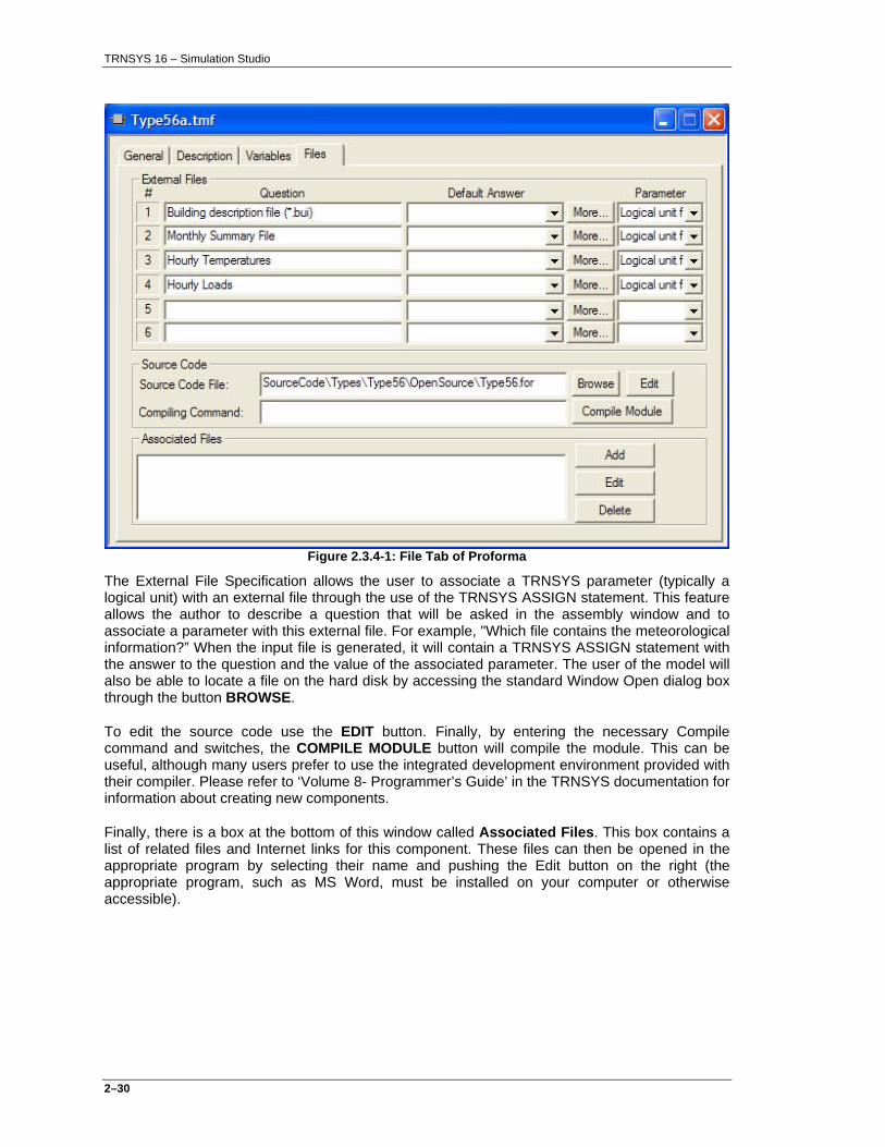
Figure 2.3.4-1: File Tab of Proforma
The External File Specification allows the user to associate a TRNSYS parameter (typically a logical unit) with an external file through the use of the TRNSYS ASSIGN statement. This feature allows the author to describe a question that will be asked in the assembly window and to associate a parameter with this external file. For example, "Which file contains the meteorological information?” When the input file is generated, it will contain a TRNSYS ASSIGN statement with the answer to the question and the value of the associated parameter. The user of the model will also be able to locate a file on the hard disk by accessing the standard Window Open dialog box through the button BROWSE.
To edit the source code use the EDIT button. Finally, by entering the necessary Compile command and switches, the COMPILE MODULE button will compile the module. This can be useful, although many users prefer to use the integrated development environment provided with their compiler. Please refer to ‘Volume 8- Programmer’s Guide’ in the TRNSYS documentation for information about creating new components.
Finally, there is a box at the bottom of this window called Associated Files. This box contains a list of related files and Internet links for this component. These files can then be opened in the appropriate program by selecting their name and pushing the Edit button on the right (the appropriate program, such as MS Word, must be installed on your computer or otherwise accessible).

TRNSYS 16 – Simulation Studio
2–31
2.3.5. Inheriting from another model
In previous versions of Simulation Studio, inheritance was strictly enforced. Inheritance allows a model to retrieve several characteristics from another model (the ‘father’ model) and then add several more characteristics. When the ‘father’ model is changed, these changes are instantly reflected in the model by the addition or removal of variables or other items. With Simulation Studio, strict inheritance is no longer enforced. Instead, it is possible to make a synchronization inheritance between models. In other words, while working in one model (Model X) it is possible to “now inherit all variables from model Y”. Then, Model X has all its original variables plus all the variables from Model Y. While not strict inheritance, this method allows Simulation Studio users to have greater control over when and to what extent inheritance occurs. Also, it is no longer necessary to have a component Library which was often confusing for the users. Synchronization inheritance is different than simply copying a file. For example, if the user has several modes of a solar collector component, much of the general information can be inherited from a primary model but each mode can be a different model with additional parameters. When a general change is made, it only needs to be made in one model and then inherited to the rest. With inheritance instead of just making copies, the user does not have to 1) make the general change in all the models or 2) redo all the additional features for each mode.
To use synchronization inheritance, first open the Proforma of the component from which inheritance will occur (the ‘father’ model). Then, click on the “Tools/Add Sons” main menu. This opens the Inheritance screen shown below in Figure 2.3.5-1. In this window, you can select one or more models which will inherit from this model.
Figure 2.3.5-1: “Sons”
Once the desired components have been selected, close this window with the OK button. Now, select "Tools/Update Inheritance" menu that will open the Inheritance settings window (see Figure 2.3.5-2). There are also some options that can be selected for this inheritance as well. These options include a listing of what can be inherited including General information, Variables, and attached Files. Also, the user can select if existing variables (such as parameters already defined in the ‘son’ model) will be saved and added to the end of the inherited variables or discarded. Once the Settings are correct, click OK to actually perform the Inheritance Update.

TRNSYS 16 – Simulation Studio
2–32
Figure 2.3.5-2: "Update Inheritance" window
2.3.6. Export as HTML
The File/Export as HTML command outputs the current Proforma in HTML format suitable for use on the Internet or for importing into text editors such as Microsoft Word. All fields of the Proforma are included in a large table-based document. In addition to creating the file, Simulation Studio starts the user's web browser to open the file. This feature is intended to allow users to easily create printed documentation for their components from Simulation Studio Proformas. This command is only visible if a component Proforma is the current active window.
2.3.7. Export as Fortran/C++
This feature is intended to allow users to more easily create Fortran or C++ code for their components described as a Simulation Studio Proforma. This command is only visible if a component Proforma is the current Active Window.
The File/Export as... and Fortran/C++ commands create a skeleton of a TRNSYS component (TYPE) for the current Proforma window. The user should enter all the parameter, input, and output information into a blank Proforma (created with File/New/Component) and save it to the hard disk (in a .TMF file). When the Export as... or Fortran/C++ command is selected, Simulation Studio uses this .TMF file to generate a source file which contains all the basic syntax for a new TRNSYS type, including the function (subroutine) definition, the reading of parameters and inputs, calling of TRNSYS checking functions, etc.
Once the source code has been generated, Simulation Studio attempts to start the user’s programming environment. If one of the recommended development environments (such as Compaq Visual FORTRAN 6.6B, Intel Visual FORTRAN, Microsoft Visual C++ 6.0 or .NET) is installed on the user’s machine, a complete, pre-configured compilation project will automatically open in that environment. (It is possible to modify the environment used under File/Settings…/Directories/FORTRAN environment and C++ environment).

TRNSYS 16 – Simulation Studio
2–33
At this point, the only missing Fortran/C++ code are the actual equations which relate the inputs to the outputs; the corresponding lines are marked with ‘?’ in the generated source code, such as
OUT(1)=?
The user can simply edit these lines to add his own equations. Of course, any existing FORTRAN or C++ source code can be added to the compilation project as usual.
Once the source is completed, the new type can be compiled (typically by using the ‘Build’ function of the compiler). The result of this compilation will be a new DLL, which is automatically created in the UserLib subdirectory. Now simulations using the new component can be run in the Simulation Studio.

TRNSYS 16 – Simulation Studio
2–34
2.4. Assembly Panel
The Assembly Panel is the window in Simulation Studio where the user will create, modify, and run assemblies of models (projects). The assembly panel can be accessed by creating a new blank project (using File/New, and selecting ‘Empty project’) or by opening an existing project using the File/Open menu item (see Figure 2.4.1-1).
The Assembly main menu provides many useful commands for working with the Assembly panel. In addition, the Project toolbar contains many icons with actions appropriate for the Assembly panel. The assembly panel actions are discussed in detail below.
2.4.1. Moving Components and Connections
To place a component model into the assembly panel, an existing component can be selected in the tree-like Direct Access Tool. Then, by clicking on the assembly panel, this component will be placed in the Assembly panel for the current project. It is possible to manipulate the assembly
panel icons with several tools. Normally, the "select" tool (an arrow pointer ) is used to select (simple left click), move (click and drag) and edit (double-click) icons. It is also possible to use the
"pan" tool ( ) to slide the entire assembly.
To move one of the component models or macros within the assembly window, the user should first make sure that the "select" tool is active. Then, the user must click on the model icon and, while holding the left mouse button down, drag the model to the new position. Any links attached to this model will move accordingly. Note that if "Snap to Grid" is selected in the View menu, the icon can only be moved at grid-spaced intervals. To place a component in between, turn off "Snap to Grid".
A link is a "pipeline" of output-input connections between two components. The details of links and connections are explained later in the manual. A user may wish change the position of a link in order to make the Assembly panel easier to understand. To move a link between two components, the user must first click on the link between the two models so that the link becomes active (small squares will appear at all corners of the link). The user must then click on one of the small squares attached to the highlighted link and, while holding the left mouse button down, drag that square to the desired location. The mouse pointer will change to a two-ended arrow when the user is on the proper place. The link will act like there is a rubber band attached to the square. A link can only be moved to a new location if the link has been defined to be a user-defined link. Refer to the "Connections" section of this manual for more information on creating and modifying links between components (section 2.6).
Holding down the Control (Ctrl-) key while clicking on a link allows to add passage points to a link, or to remove them (when clicking on an existing passage point). .

TRNSYS 16 – Simulation Studio
2–35
Figure 2.4.1-1: Sample Assembly Panel
To view the lists of parameters, inputs, outputs, derivatives, special cards, external files and comments associated with a component model, the user must right-click on the component icon and select the Variables item. Alternatively, the user can use the menu item Assembly/Variables which will open the Variables window for the currently selected component.
To rename a component model, double-click on the name of the desired model so that a cursor appears in the name of the model. Retype the name using the keyboard. The name must be unique. Press the Return key to validate the new name of the component.
To select multiple items in the program, users may utilize one of two methods. Items may be selected or deselected sequentially by clicking on the selected components with the mouse while holding the SHIFT key. Users may also click on an empty area of the assembly panel and, while holding the mouse button down, slide the cursor to a new location. Every item that is contained within the box formed by the drag will be selected. Once multiple items have been selected, these items can be moved by clicking on one of the selected components with the left mouse button and dragging it to a new location.
By pressing the F2 key, the names of the components will be replaced with the component’s Type and Unit numbers.

TRNSYS 16 – Simulation Studio
2–36
2.4.2. Deleting Components
The user can delete a model or a link between two models by selecting the item with the left mouse button and then pressing the DEL key or using the Edit/Cut menu command.
2.4.3. Undoing/Redoing an operation
The Edit/Undo menu item allows the user to undo the previous operation. For example, the user may undo the linking of two components, or the deletion of a component model.
2.4.4. Duplicating or Copying Components
The Edit/Copy menu command allows the user to make an exact copy of one of the component models in the Assembly Panel window. To use this tool, click on the component model to be duplicated and then select the menu command Edit/Copy. Then select Edit/Paste to place the copy on the Assembly Panel, and move it to the desired location. The new model will have all the information that the user has entered in the initial model.
2.4.5. Using the Direct Access Toolbar
The Direct Access Toolbar (see Figure 2.4.5-3) allows users to quickly and easily retrieve any of the component models and place them on the assembly panel. To use this tool, select a component in the tree structure and click on the assembly panel. A corresponding component is added to the assembly panel. This tree structure is also accessible from the Direct Access Menu/Insert Model (see Figure 2.4.5-1).
Figure 2.4.5-1: Direct Access Tool
When clicking this menu, a dialog appears containing all available components (like in the Direct Access Tool).
Referring to Figure 2.4.5-2, the multi-zone building component has been selected; TYPE56b. Through this process, the user will make several choices about the model he will select and also the “operation mode” of that component. The main TRNSYS manual has very detailed information about the different modes of the different components.

TRNSYS 16 – Simulation Studio
2–37
Figure 2.4.5-2: Direct Access Menu with TYPE56b chosen
Once a component has been selected, close the dialog and the cursor will change to a plus sign (+). Move the cursor to the point on the Assembly Panel window where the component model should be placed and click. The component model will appear in the Assembly Panel.

TRNSYS 16 – Simulation Studio
2–38
Figure 2.4.5-3: Direct Access Toolbar with type56b chosen
2.4.6. Getting Information (Accessing the Proforma)
There are several methods for accessing the Proforma for a component or macro on the Assembly Panel. First, select the component using the Select tool and then select the information
icon ( ) from the Project toolbar or Assembly/Proforma menu item. Otherwise, by right-clicking on an icon the user can select "Proforma" from the right-click menu. The Proforma contains a complete description of the component model from an overview of the model's function to descriptions of all the required parameters, inputs, outputs, and derivatives. It can be modified from the Assembly panel in Simulation Studio. Refer to the "Proforma" section of this manual for more information.
2.4.7. Changing the Layer of the Component Each component is assigned "layers" on which it, and the links to other components on the same layers, will be displayed. Any combination of layers can be displayed at any time. The idea is to maintain the components on separate layers. There are many pre-defined layers but the user may also create his own layers in the configuration window under File/Settings/Layers. The pre-defined layers include: Weather / Data Files, Water Loop, Main, Air Loop, Outputs, and Text. To move one or more components to a different layer, select one or more components and then click the Assembly/Send to Layer menu item. A submenu will appear with all the defined layers. Click on one of these choices and the components will be moved to this layer. Links between

TRNSYS 16 – Simulation Studio
2–39
components on the same layer are visible. Links to components on other layers are shown if the components from both layers are shown. Links can be made between components on different layers. Of course, it is always possible to see all the components (and all the links) by clicking on the “All Layers” on the menu 'View/Show Layers ' menu, which is the default.
2.4.8. Creating Links
The Assembly/ Link Mode menu command allows the user to specify information flow between two component models. The direction of information flow is from the first model to the second model (outputs of first model ==> inputs of second model). Inputs to a model are always represented as a line flowing into the left side of a component icon. Outputs from a component model are always represented as a line leaving from the right side of the component icon. To connect the outputs of one component to the inputs of another component, the user has several methods to choose from.
To make many links: The best way to operate when you want to make many links is to turn on the Link Mode using the Assembly/Link Mode menu item. Then, the cursor will change to reflect ongoing link operations which is normally a crosshair (+). When the cursor is above a component that can start or begin a link, the cursor appears as a crosshair in a circle. When the user clicks on a component to begin the link, the link is shown as a straight line between the component and the cursor (once the cursor is moved away from the component). The user must complete the link process by clicking on the component model to which the outputs of the first model will be connected. A segmented line will be drawn between the two components to indicate information flow between the two components. This segmented line will initially be colored blue to signify that the there is information flow between the two components, but that the flow on a variable level has not yet been defined. When the information flow is specified on a variable level, the link will turn black. When the user is done making links, the Link Mode can be turned off by re-selecting the Assembly/Link Mode menu command.
To make just one link: The user can select the starting component, then use the right mouse button to select “Start Link” from the right-click dropdown menu. Then, the cursor will change to reflect an ongoing link operation. Users must complete the link process by clicking on the component model to which the outputs of the first model will be connected. After that, clicking on a component will not start another link. Thus, a single link is created in this way.
If a user wishes to specify the position of the link joining the two components, the user should first click on the component from which the outputs will come. Subsequent clicks on open spots in the Assembly Panel window will cause joints to be placed in these positions. The link will then act like a rubber band which has been attached to this joint. Users should end the user-defined link by clicking on the component which will receive these outputs.
To specify which outputs of the first model are connected to which inputs of the second model, the user should double-click on the link between two components. A link window will appear in which the user can specify the detailed input/output connections. Refer to the "Connections" chapter for more information.
2.4.9. Creating a Macro Component
The macro concept allows the user to replace selected components, and the connections between these components, with a single macro-model. The macro-model will have:
• as parameters: the parameters of all its contained models

TRNSYS 16 – Simulation Studio
2–40
• as outputs: the outputs of all its contained models
• as inputs: the unlinked inputs of all its contained models
• as derivatives: the derivatives of all its contained models
• as external files: the external files of all its contained models
• as special cards: the special cards of all its contained models
The macro-model behaves like any other model. It can be moved, used to create other macros, deleted, saved as a model, etc. To create a macro-model, first select the models to be replaced with a macro-model by holding down the SHIFT key to select several components or draw a box around several components to select them. Then, click on the Assembly/Create Macro menu
item, or click on the button ( ) on the Project Toolbar. The program will replace the selected models with a macro-model.
2.4.10. Exploding an existing macro
The Assembly/Explode Macro menu item is used to substitute a macro-model by the components and connections that were used to create the macro-model. Selecting a macro-model and then clicking this menu command will replace the macro-model by its components and connections. If the user just wishes to view the macro, or slightly modify the macro-model, the user should open the macro model.
2.4.11. Opening an existing macro
The Assembly/Open Macro menu item is used to create an additional assembly panel that displays the components and connections that were used to create the macro-model. The user can also open the Macro by double-clicking on it. The Assembly/Close Macro menu item closes the assembly panel displaying the macro.
2.4.12. Saving a Macro
The File/Save As menu item allows the user to store a macro-model. To do so, the user must select the desired macro-model, then click on File/Save As menu item. A window will appear prompting the user to supply a name to the saved macro-model.
2.4.13. Saving a Project
The File/Save or File/Save As tool allows the user to save the entire contents of the Assembly Panel window as a project. A new project has automatically been saved after its creation in the MyProjects directory in the installation directory. Users should ‘clean’ this directory regularly, to remove old and unused projects. Projects can be stored or copied anywhere on the hard disk.

TRNSYS 16 – Simulation Studio
2–41
2.4.14. Adding or removing the TRNSYS Trace command
The Assembly/Add-Remove Trace tool is used to inform the TRNSYS simulation program which component models should be traced during the simulation. Selecting one or more of the components and then clicking this menu command or the Trace icon on the Project toolbar will tag this model with footprints similar to the icon of the Trace tool (see Figure 2.4.14-1). Alternatively, the Trace tool can be selected first and then components can be marked for tracing by selecting them with the active Trace tool. The TRNSYS program will trace this component (list all the parameters, inputs, outputs, and derivatives at each call to this component) from the beginning of the simulation to the end of the simulation. Selecting a component which is already being traced and then clicking this component will remove the trace tag from the component model. Care should be taken when tracing components as voluminous data can result from a relatively short simulation. Please refer to “Volume 7 TRNEDit: Editing the Input File and Creating TRNSED Applications” for more information on the TRNSYS trace command.
Figure 2.4.14-1: Traced Component Model
2.4.15. Adding Text to the Assembly Window
The Assembly/Add Text menu item or Add Text icon on the Project Toolbar ( ) allows the creator of a project to insert text strings onto the Assembly panel itself. These text strings allow the user to remind themselves of certain characteristics of the project. This is also useful when the Assembly panel is printed. To use this feature, click on the Add Text menu item and then click a space on the Assembly Panel at which point the user can start typing in the desired text. The text will be added on the text layer.
2.4.16. Locking and Unlocking Components
The Assembly/Lock-Unlock menu item or Lock toolbar item ( ) allows the creator of a project to lock certain components in the assembly panel. These locked components cannot be erased nor modified. Selecting one of the components and clicking this command will tag this model with a padlock as shown in Figure 2.4.16-1. Clicking again on this command will unlock the model. The locked/unlocked status of the model will be preserved when the assembly is saved as a project. If TRNSED commands are being automatically written to the TRNSYS input file, no TRNSED statements will be written if the entire Component is locked.
Figure 2.4.16-1: Locked Component Model

TRNSYS 16 – Simulation Studio
2–42
2.4.17. Accessing the Simulation Control Cards
The Assembly/ Control Cards menu command allows the user to specify the simulation control cards which are required by the TRNSYS program. The control cards can also be accessed quickly by right-clicking on a blank area in the Assembly Panel and selecting "Control Cards..." from the drop down menu. Clicking on this tool will open the Control Cards window as shown in Figure 2.4.17-1.
Figure 2.4.17-1: Control Cards Window
In this window, users must specify the control cards to be used in the simulation. Users should refer to Volume 8 ‘Programmer’s Guide’ for a complete description of the TRNSYS control cards. Users have the ability to lock (or unlock) any or all of the control cards for a simulation by clicking on the locks scattered throughout the control card window. Locked control cards can not be changed. All the locks in the window can be locked by clicking the Lock All Button at the left side of the window. The control cards will be written to the TRNSYS input file specified in the 'Deck file name' input box.
The value for the 'Simulation start time', the 'Simulation stop time', and the 'Time step' will be written as TRNSYS equations with the equation names 'START', 'STOP', and 'STEP' respectively. These equation names can be used in the equations component or as parameters to any component model (the printer component for example). Refer to the "Equations" section of this manual for more information on using these equations.

TRNSYS 16 – Simulation Studio
2–43
Note that next to the location of the Simulation Input File Name box is a BROWSE button which allows the user to search the hard drive for the location and name of the filename they wish to use for the TRNSYS input file. The name and path for the list file is identical to the input file except for the extension which is automatically *.lst.
The "Component Order" tab will open another window in which the user can reorder the components in the simulation as shown in Figure 2.4.17-2. By default, the components and equation blocks appear in the order in which they were placed in the Assembly Panel window. By selecting a component, holding the left mouse button down and sliding the component up or down, the component can be moved earlier or later in the input file. The unit number generated in the deck file can be modified by clicking with the mouse or pressing F2 key on the corresponding line.
The Optimize components order button will optimize the order for the simulation to be more efficient.
Figure 2.4.17-2: Component Order Window
2.4.18. Generate the Input File Only
The Calculate/Create Input File menu item or the Write Input File toolbar icon ( ) allows users to generate the input file only without running the simulation. This capability can be very valuable when the user wants to check that all the components are currently connected properly without starting a simulation (that the user knows will not run properly because the simulation is not completely constructed).

TRNSYS 16 – Simulation Studio
2–44
2.4.19. Accessing the Generated Input File (*.dck)
The Calculate/Open / Input File menu item or the Deck File toolbar icon ( ) allows users to access the generated input file through Simulation Studio. The file, which Simulation Studio has generated, will be opened in the editor window which is Notepad by default. If the user edits this file and saves it, the changes will NOT be simulated. When the Run Simulation command is selected, the input file is overwritten with a new version and changes are lost.
2.4.20. Running the Simulation
The Calculate/Run Simulation menu item or Run toolbar icon ( ) allows the user to run the TRNSYS simulation program on the currently opened project. Clicking on this command starts the following process:
• The project is saved and checked for any errors or omissions which Simulation Studio can find (verified).
• The TRNSYS input file is generated from the project.
• The TRNSYS simulation program is run with the newly created input file.
Once the TRNSYS program has finished the simulation, control is returned to the Simulation Studio program where the results can be analyzed, graphs can be created, or additional simulations can be run. Care should be taken when analyzing the results from a simulation as neither TRNSYS nor Simulation Studio automatically delete the output, list, and plot files when a new simulation is run. If a new simulation fails, the output and plot files may be from the previous successful simulation of this input file. Users should always check the TRNSYS list file for sources of warnings or errors before analyzing the results.
2.4.21. Accessing the List File (*.lst) through the Error Manager
The Calculate/Open/List File menu item or the List File toolbar icon ( ) allows users to access the Error Manager, which analyzes and parses the list file which is generated by TRNSYS during a simulation. The file will be opened in the Error Manager (see Figure 2.4.21-1). This dialog contains all generated TRNSYS error messages and is the first place to check when the simulation fails to run.

TRNSYS 16 – Simulation Studio
2–45
Figure 2.4.21-1: Error Manager - Messages tab
The error manager window contains 4 tabs: Messages, Units stats, Types stats and Lst file...
2.4.21.1. Messages tab
This tab contains a table on the top which summarizes all messages that occurred during the simulation. For each message,
• Severity is the type of message. It can be notice, warning and error.
• Time is the time when the message appeared during the simulation.
• Unit is the unit number of the component that is responsible of the message (if available).
• Type is the type number of the component that is responsible of the message (if available).
If the type / unit number information is available, double clicking on a row will open the corresponding component properties to check the validity of the parameters. This information may not be available if an error cannot be assigned to a particular component (e.g. error in global information, etc.).
Note that at the bottom, check boxes are available for filtering displayed messages.

TRNSYS 16 – Simulation Studio
2–46
2.4.21.2. Units stats tab
Figure 2.4.21-2: Error manager - Units stats tab
This tab contains a table at the top which summarizes time of calculation spent for each unit.
The check box at the bottom can be used for filtering displayed rows, depending on the selected unit number.

TRNSYS 16 – Simulation Studio
2–47
2.4.21.3. Types stats tab
Figure 2.4.21-3: Error Manager – Types stats tab
This tab contains a table at the top which summarizes time of calculation spent for each type.
The check box at the bottom can be used for filtering displayed rows, depending on the selected type number.

TRNSYS 16 – Simulation Studio
2–48
2.4.21.4. Lst file... tab
Figure 2.4.21-4: Error Manager – Lst file… tab
This tab displays the content of the .lst file, which contains all messages that appeared during the simulation. The default editor (see File/Settings/Directories) is used.
2.4.22. Opening Output Files with Spread (Spreadsheet Tool)
The Assembly/Open in Spreadsheet tool launches the spreadsheet application, as configured under File/Settings…/Directories/SPREAD application. To use the spreadsheet, the user must select the icon of the printer model which contains the data to be loaded into the spreadsheet and then click on the menu command.

TRNSYS 16 – Simulation Studio
2–49
2.5. Variables An important step in the creation of an assembly in Simulation Studio is the specification of the required variables for each component model. The specific variable (input, output, parameter, and derivative) window can be accessed in the assembly panel by double-clicking the desired model icon. The parameters, inputs, outputs and derivatives are all available in a single window using a tabbed view. The user is required to specify all the parameters, the initial values for all the inputs, and any derivatives that may be present in the model. The output window is just for informational purposes. Failure to provide any of this information to the component model will result in default information being used for the component.
The different variable tabs contain some unique features, but are all very similar in look and operation. The inputs window for a TRNSYS radiation processor is shown in Figure 2.4.22-1. Each variable set contains important variable information organized into rows of data. Each row contains:
• The number of the input, output or parameter.
• A symbol to indicate whether this variable is locked or unlocked .
• The name of the variable.
• An input box containing the current value for this variable. This value may be changed only if the variable is unlocked. The new value for the variable must lie within the bounds specified by the author of the component model. The output window does not contain this input box for obvious reasons.
• The current unit for the variable.
• A 'more' button to allow users additional detailed information on a variable.
If a specialized, external program (a so-called plug-in) is available to edit the variables of a
component, an icon representing a magic stick ( ) appears in the bottom-left corner of the variable window. Pushing this button will activate open the external application. An example is the function editor for type 14 (under Utilities/Forcing functions).

TRNSYS 16 – Simulation Studio
2–50
Figure 2.4.22-1: Inputs Window
The variable windows contain set of tools that are explained in detail below:
2.5.1. Locking and unlocking Items
To lock or unlock a variable, click on the lock symbol located directly to the left of the variable name or directly on the name of the variable. The lock symbol for that variable will change to indicate your choice. The value for locked parameters is grayed to indicate that the value can not be changed. An example of an unlocked parameters line and a locked parameters line are shown below:
Figure 2.5.1-1: Example of Locked and Unlocked Variables
2.5.2. Locking or Unlocking all the Variables
If the user wishes to lock all the variables, a single click on the Lock/Unlock All button ( ) will perform the task. Clicking again on the Lock/Unlock All button will unlock all the variables in the window.

TRNSYS 16 – Simulation Studio
2–51
The locking of a parameter, input, or derivative has important effects if TRNSED mode is used (Assembly/Control Cards/Write TRNSED commands; see the TRNBuild manual for details). An unlocked parameter or unlocked initial value of an unconnected input will be written to the generated TRNSYS input file in TRNSED format. Only these variables that are written in TRNSED format can be 1) changed by a user in the TRNSED program and 2) put into a parametric table in TRNBuild. Therefore, the decision to leave a parameter locked or unlocked should be made with some thought.
To change the current value for a variable, the user must click in the input box containing the current value and enter a new value. Pressing the arrow keys or TAB key will place the cursor in the next value to edit. This value may be changed only if the variable is unlocked. The new value for the variable must lie within the bounds specified by the author of the component model. The output window does not contain this input box for obvious reasons.
To change the units for a variable, the user must select the current unit. By clicking on the current unit with the mouse or by selecting "Alt" + Down-Arrow will make the drop down menu appear. A pop-up menu will appear with available choices of units for this variable (based on the dimension of the variable). Choose the new unit and the box will disappear. The value of the variable will change to reflect your new choice of units. Users do not have to worry about specifying a variable in the correct unit system. The Simulation Studio program will automatically convert the variable to the correct set of units as required by the TRNSYS simulation program. The units required by the TRNSYS program can be seen if the More button is pressed. The required unit is that unit shown in the 'Unit' input box.
Clicking on the more button will bring up a window of detailed information on the variable. A sample Variable Detail window is shown in Figure 2.5.2-1.
Figure 2.5.2-1: Variable Information Window

TRNSYS 16 – Simulation Studio
2–52
This window is used primarily to get detailed information on a TRNSYS variable.
If a user wishes to use a TRNSYS equation name, or constant, as the value for a parameter or the initial value of an input, the Type button should be pressed and the variable type changed from its current status to "string". This will allow the user to type the name of the equation or constant into the value input box. Care should be taken when using equation names as parameters or initial values of inputs as time-varying equations will cause problems with the TRNSYS equation solver. Please refer to “Volume 7 TRNEDit: Editing the Input File and Creating TRNSED Applications” for more information on equations and constants. Users wishing to use equations as inputs to a component are required to use the equations component. Users may also change the units for this variable in this window. Refer to the description of the Variable Detail window contained in the Proforma chapter of this manual for more information (section 2.3).
The Proforma can also be opened by clicking on the information button ( ).
In many components, there are special cards to be filled in, cycles to be specified, or external files to be specified and comments. These topics are discussed below. Detailed information about special cards, cycles, and external files can be found in the "Proforma" section of this manual.
2.5.3. Special Cards
Special cards require the user to specify some additional information that is needed by the component. A good example is the TYPE 65d Online plotter, shown below in Figure 2.5.3-1, which requires the specification of the labels for the Y-axis and title. The additional information should be entered in the input boxes provided.

TRNSYS 16 – Simulation Studio
2–53
Figure 2.5.3-1: Special Cards Example
2.5.4. Cycles
In many components, the number of parameters, inputs, outputs, or derivatives depend on the answer to a question posed to the user. Users must enter a number in the input box provided that lies within the specified validity range. An example of a cycle is shown in Figure 2.5.4-1.
Figure 2.5.4-1: Dialog for input cycle.
In this example, the number of outputs for the Type 16 radiation processor depends on how many surfaces for which the user wishes to have the radiation calculated. The number of outputs (or inputs, derivatives, or parameters) will change to reflect the answer to this cycle.
In some cases, the ‘size’ of a cycle (the number of variables contained in it) may also be determined by the value of another parameter.
For some special models, such as the multi zone building model (type 56), the number as well as the names of the variables depend on some external file (e.g., the building description file). The inputs and outputs of these components adapt to the contents of such an external file. For example, if the user adds an additional thermal zone to a building in TRNBuild, additional default outputs (such as the zone temperature) will be added to the list of outputs. The right-mouse-click menu ‘Update building variable list’ can be used to update these lists.
In the case of the coupling with the air flow simulation tool COMIS (type 157), the output variable names will automatically adapt as a function of certain parameters. For example, setting parameter 8 of type 157 (‘Output-1’) to ‘2.3’ will cause the first output of this component to be named

TRNSYS 16 – Simulation Studio
2–54
‘Fma 2->3 (Coupling flow from COMIS zone 2 to COMIS zone 3 [kg/h]) -1’
instead of just ‘Output 1’.
2.5.5. External Files
In most of the output producing components, it is common for the user to be prompted to specify the name of an external file which will contain the output data. This is accomplished in Simulation Studio by the use of an external file specification. Users can enter the required information in the input box or browse the hard disk for answers for this question. An example taken from the TYPE 25 printer is shown below in Figure 2.5.6-1.
The user may wish to browse for the proper file on the hard drive. The browsing window can be
opened by pressing the "Browse" button next to the file name ( ).
2.5.6. Comment Comment can be specified in the comment tab (see Figure 2.5.6-2). This comment will be written to the TRNSYS input file. A plug-in path can also be specified. A plug-in is an executable file (.exe) that can be used to edit component properties. It can be graphical and as complex as needed (see Appendix 2 How to create new Plug-ins).
Figure 2.5.6-1: External Files Example
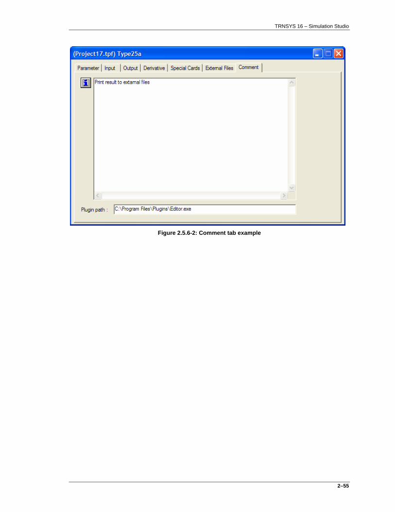
TRNSYS 16 – Simulation Studio
2–55
Figure 2.5.6-2: Comment tab example

TRNSYS 16 – Simulation Studio
2–56
2.6. Connections
With the specification of the values for the variables in the component models complete, it is important that users specify how information flows from one component to another. In Simulation Studio, this information flow is indicated by a link between two components in the Assembly Panel window. However, the link shown on the assembly panel is purely informational. Users must specify the details of the link between two components to actually flow information from one component to another. To specify the details of a link between two components, the Connections window is used. The Connections window is opened when the user double-clicks on the link between two components or use mouse right click and Edit connections with....
The Connections window contains two tabs (see Figure 2.6.1-1 and Figure 2.6.1-2), “Classic” and “Table”. The first tab is the classic one used in previous version of Simulation Studio, the second one is a table which summarizes all connections involved between the two connected components. Both tab are dependant and updated depending on user interactions on each tab.
Each tab has two columns of variables. The first column contains the outputs of the first component model while the second column contains the inputs to the second component model. For reference, the names of the component models being linked appear above in the title bar of the Connections window. Any input that is left unconnected in a component after all connections have been made to this component will be assumed to be constant at its initial value for all time.
In the classic tab, to specify the information flow for these two components, users must connect the outputs of the first component (left-side) to the required inputs of the second component (right-side). Inputs and outputs that have been connected, either in this window or in another Connections window, will be listed in black. Inputs and outputs which have not yet been connected will be colored blue. Remember, in TRNSYS, inputs can have only one connection while outputs may have several connections. Highlighted links will appear in red. To the right of the inputs column are input boxes for the specification of the initial values of the inputs. The initial values of the inputs could be entered here or in the inputs tab of the Variables window. To change the initial values, press the button for the Select tool to change from the connection tool (which is the default tool). Then, click on the initial value that you wish to change. To change the initial values in the Variables window, refer to the "Variables" section of this manual for more information.
In the table tab, only connections are displayed. In other words, if no connections are available between the two involved components, no line will appear in the table. To specify the information flow for these two components, users must add a line and specify the output (left combo box) and input (right combo box). Then, the classic tab is also updated and a new connection appears.
2.6.1. Creating a Connection
In the classic tab:
Clicking on the name of an unconnected output (left column) and then clicking on the name of an input (right column) will draw a line between the input and the output. These two variables are now connected. Inputs may only be connected to one output, but outputs may be connected to many different inputs. Simulation Studio will only allow users to connect variables of the same dimension, i.e. 'temperature' to 'temperature'. Inputs that have already been connected in a

TRNSYS 16 – Simulation Studio
2–57
previous connection window cannot be used in this connection window and will be colored black. This is done to avoid linking an input to two or more different outputs.
Figure 2.6.1-1: Connections Window – Classic tab
In the table tab:
Clicking on the Link button ( ) will add a new line (i.e. a new connection) between the two components. By default, the connection is created between the two first compatible variables found (i.e. the two variables have the same dimension and unit). Once the connection is added, it can be modified by selecting other variables in the corresponding combo box (for input or output variable).

TRNSYS 16 – Simulation Studio
2–58
Figure 2.6.1-2: Connections Window – Table tab
2.6.2. Selecting a connection
In the classic tab:
Sometimes, it is difficult to determine (because of many crossing lines) the connection location. Therefore, if the user clicks on either an input or output that is already connected, this will “highlight” the link. Both the connected input and output names as well as the link line will change
color to red. The use of the align button ( ) will align the elements in the selected connection for easier visualization.
In the table tab:
Clicking on the row header will select the corresponding connection. Then, the row is highlighted in black.
2.6.3. Deleting a connection
The Delete Connection button in the Connection window ( ) allows the user to delete an input-output connection.
TRNSYS 16 – Simulation Studio
2–59
In the classic tab:
Clicking on either the name of the input or the name of the output will highlight the connection (change the connection line and the other variable name to the color red). The user can then delete the line joining the two variables by pressing the Delete connection button. This action deletes the information flow between these two variables.
In the table tab:
Clicking on the row header will select the corresponding connection, which can be deleted by clicking on the Delete Connection button.
2.6.4. Get Information on a Variable
Only available in the classic tab:
Double-clicking on a variable name is used to view detailed information about a particular input or output. Double-clicking on the name of an input or output will open the Variables window as shown in Figure 2.4.22-1. Then, the user can press the "More" button for the input or output about which they are interested in getting detailed information.
2.6.5. Deleting multiple links
The user can delete all the links by clicking on the Delete All Links button ( ) on the left of the window.
2.6.6. Link Positioning
The button on the bottom of the connections window ( ) is used to define how a link between two components will move when one of the components, or the link itself, is moved. Depending on if the button is "pressed" or not, it determines if the link will follow default positions or user-defined positions. This can also be changed from the right-click menu of the link in the Assembly Panel.
2.6.6.1. User Defined Positions for Links
If the link position button is "extended", it indicates that the link between two components will be user-defined in its path from one component to another. When this choice is active, the link will not follow the movement of one of the components. Instead, the part of the link closest to the component will stretch as the link is moved. When the link is in this mode, it may be repositioned by the user.

TRNSYS 16 – Simulation Studio
2–60
2.6.6.2. Default Positions for Links
If the link position button is "pressed", it informs the Simulation Studio program that the link between two components should be reset to default positions when one of the components in the link is moved. In this mode, all bends in the line between two components will occur at 90 degree angles.
Figure 2.6.6-1: Default position for links Figure 2.6.6-2: User defined positions for links

TRNSYS 16 – Simulation Studio
2–61
2.7. Equations
A very useful feature in TRNSYS is the ability to define equations within the input file which are not in a component. These equations can be functions of outputs of other components, numerical values, or previously defined equations. These equations can then be used as inputs to other components, or as parameters, initial values of inputs, or derivatives if the equations are time independent. Refer to “Volume 7 TRNEDit: Editing the Input File and Creating TRNSED Applications” for more information on the use of equations. In Simulation Studio, the use of equations is most easily accomplished by using a special equations component. This equations component can be placed in an assembly or saved like any other component.
The equation component will not be represented in the generated input file by a UNIT, TYPE statement. Rather, the information contained in this component will be placed in an EQUATIONS statement within the TRNSYS input file. The user can specify the location of the equations in the Control Cards window. Different blocks of equations can be placed anywhere within the input file and are arranged just like different components.
To add equations to an opened assembly panel, select Assembly/Insert New Equation. When put in place in the assembly panel, the equations component can be linked to the outputs and inputs of all other components as if it were a normal component. Double-clicking on the "equa" icon will open the dialog box used to create the equations. This window can be seen in Figure 2.6.6-1.
This window contains:
• Special operators defined in TRNSYS (SIN, AND, GE, etc.) as buttons
• A keypad of numbers that can be clicked with the mouse.
• A list of variables that are used in equations (intermediates) or outputs that are defined in the equations component (list box located in upper right corner)
• A list of variables that are inputs to the equations (upper left corner)
• A box that will display the current variable being defined by an equation (middle left)
• A box containing the actual equation (middle right)
• TIME (the current simulation time), START (the simulation start time defined in the control cards), STOP (the simulation stop time defined in the control cards), and STEP (the simulation timestep defined in the control cards) are included with the special operators.
The variables that are defined in the equations component can be thought of as outputs from the equations model. These outputs can then be linked to inputs of other components. Likewise, the variables defined as inputs to the equations will be displayed as inputs to this "equa" component and can be linked to the outputs of other components.
The following steps should be followed to enter an equation:
1) Decide what variable names will be inputs to these equations and what variables will be outputs from these equations.

TRNSYS 16 – Simulation Studio
2–62
Figure 2.6.6-1: Equation Window
2) Click on the "Add a new input variable" button next to the inputs box ( ). It is usually best to rename the new input variable with a meaningful value. The equations in the "equa" component can be saved and used in future projects so the more memorable the name is, the better it is.
3) Once all the necessary inputs are defined in the input box, do the same for output variables in the upper right hand box. Again, click on the “Add a new output variable" button and enter an appropriate name for this output variable.
4) The next step is to define the relationship between an output variable and one or more input variables. Therefore, select an output variable by clicking on it. Then, click on the "Select the
output for edition" button ( ).
5) Now, the desired output should appear in the middle left box. The user has several options to enter the equation:

TRNSYS 16 – Simulation Studio
2–63
Click on the TRNSYS special operator buttons to place them in the equation box.
Select an input or previously defined output and then click on the "Place in equation" button
( ) to place it in the equation.
Simply type in the equation box. Simulation Studio is monitoring what is typed. If it does not recognize a variable name as either an input, an output, or a special operator, then the variable name is displayed in red. As a variable name is typed into the box, the text will be red until completely entered.
6) Close the Equation window and make links to other components to connect the inputs and outputs. The equation component is just as any other component at this point.
Figure 2.6.6-2 demonstrates the completion of an equation entered into the window.
Note that user can specify a plug-in path to manage its equation with a plug-in (see Appendix 2 How to use a plug-in).
Figure 2.6.6-2: Complete Equation in Equation window

TRNSYS 16 – Simulation Studio
2–64
2.8. Main Window The Main window is what users first see when entering the Simulation Studio program. As with other MS Windows programs, it consists of a series of pull-down menus, several toolbars and one or more active windows. On start-up, the main window is empty. Normally, the Assembly Panel will be shown in the main window after the user creates a new project or opens an existing project. Additionally, all other necessary features of Simulation Studio and other TRNSYS tools can be accessed through the main window of Simulation Studio. Several of these features will launch separate programs which will open in their own windows. In the main Simulation Studio window, there are several drop-down menus across the top of the screen as shown in Figure 2.8.1-1. Depending on the current operation occurring, these windows are either usable or "grayed-out". The menus and submenus are described here.
2.8.1. The file menu
The File menu is the first menu option on the left of the Menu Bar. The File Menu offers choices for opening, saving, and printing Simulation Studio components, projects and text files. This menu also contains items for Importing Simulation Studio 2 components and libraries as well as menu items for Exporting Proformas as HTML or for Generating Fortran code from the Proformas. Finally, the important configuration and setup options for TRNSYS are also within the File Menu. The File menu commands are shown in Figure 2.8.1-1 and explained below.
Figure 2.8.1-1: The File Menu

TRNSYS 16 – Simulation Studio
2–65
2.8.1.1. File/New
The New command creates a new empty project, component, multizone building project, simplified building project or solar hot water project in Simulation Studio. The New menu item creates a wizard dialog box with a list of options (see Figure 2.8.1-2): New Component, Empty Project, Solar Hot Water System, Multizone Building Project and Simplified Building Project. Depending on what kind of new item is created, different events occur.
Figure 2.8.1-2: Wizard dialog box
If File/New/Empty Project is selected and Create button clicked, a blank assembly panel is presented to the user called "ProjectX", where X is the current index project in the MyProjects directory. *.TPF is the standard ending for an Simulation Studio Project File (abbreviated from TRNSYS Project File). Into this window, a user would place several Simulation Studio icons in order to connect them together and generate a simulation.
If File/New/New Component is selected and Create button clicked, a blank component Proforma is created. This Proforma is entitled "Component1". Into this Proforma, the user should type all information about the component. See the discussion later in this manual for details about the Proforma (section 2.3). When the user has finished with the Proforma, it can be saved using the Save menu item within the Proforma window. Note that it is important where the component is saved as the Direct Access menu will locate the model based on its location on the hard disk. This is further described in the discussion on the Direct Access Menu (section 2.2.3). Note also that the standard ending for Components is *.tmf (short for TRNSYS Model File). It is important that the user follow this convention.
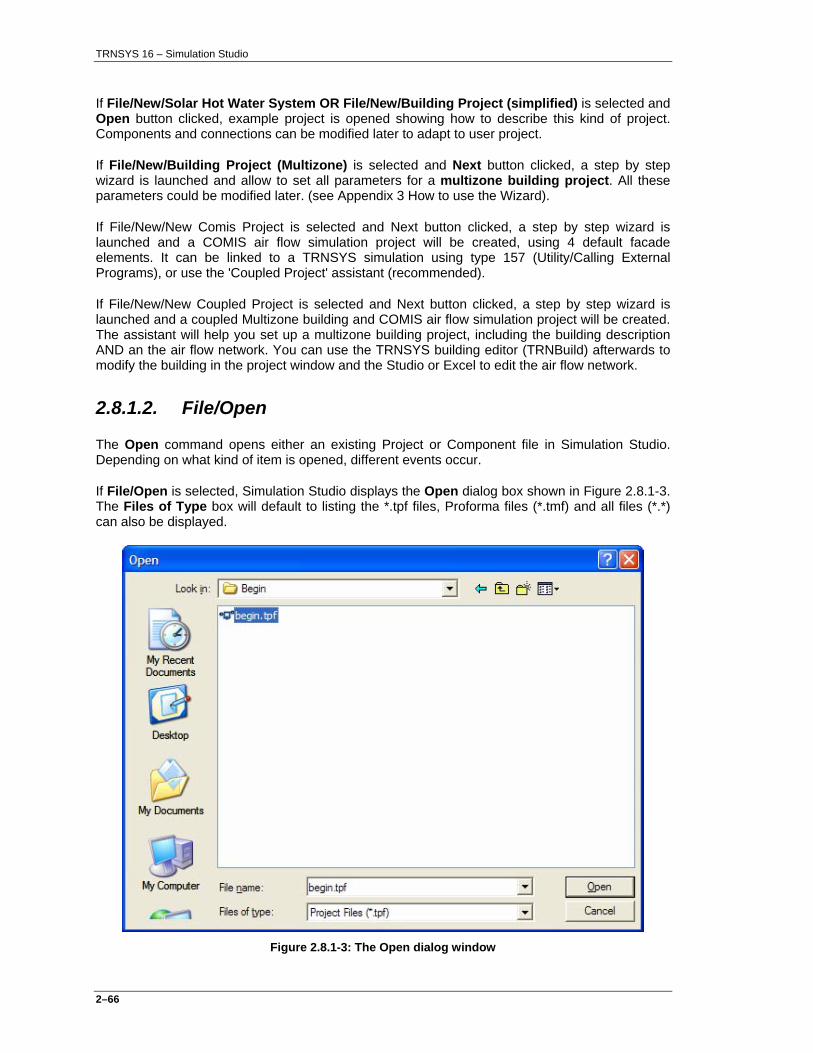
TRNSYS 16 – Simulation Studio
2–66
If File/New/Solar Hot Water System OR File/New/Building Project (simplified) is selected and Open button clicked, example project is opened showing how to describe this kind of project. Components and connections can be modified later to adapt to user project.
If File/New/Building Project (Multizone) is selected and Next button clicked, a step by step wizard is launched and allow to set all parameters for a multizone building project. All these parameters could be modified later. (see Appendix 3 How to use the Wizard).
If File/New/New Comis Project is selected and Next button clicked, a step by step wizard is launched and a COMIS air flow simulation project will be created, using 4 default facade elements. It can be linked to a TRNSYS simulation using type 157 (Utility/Calling External Programs), or use the 'Coupled Project' assistant (recommended).
If File/New/New Coupled Project is selected and Next button clicked, a step by step wizard is launched and a coupled Multizone building and COMIS air flow simulation project will be created. The assistant will help you set up a multizone building project, including the building description AND an the air flow network. You can use the TRNSYS building editor (TRNBuild) afterwards to modify the building in the project window and the Studio or Excel to edit the air flow network.
2.8.1.2. File/Open
The Open command opens either an existing Project or Component file in Simulation Studio. Depending on what kind of item is opened, different events occur.
If File/Open is selected, Simulation Studio displays the Open dialog box shown in Figure 2.8.1-3. The Files of Type box will default to listing the *.tpf files, Proforma files (*.tmf) and all files (*.*) can also be displayed.
Figure 2.8.1-3: The Open dialog window

TRNSYS 16 – Simulation Studio
2–67
2.8.1.3. File/Close
The Close command closes the active TRNSYS project. Several TRNSYS projects, represented by their Assembly Panels, can be open simultaneously. The Close command closes the project with the active window. If your project has not been saved, Simulation Studio will ask you if you want to save the file before it is closed.
2.8.1.4. File/Save
The Save command saves the active project to disk. If, for example, the Save command is issued with a Assembly panel project named TEST.TPF as the active window, the file TEST.TPF will be overwritten. Note that the keyboard shortcut CTRL-S will also save the project.
2.8.1.5. File/Save As
The Save As command displays the Save As dialog box (see Figure 2.8.1-4). The Save File As input box is used to enter the desired file name to save the project under or the file-mask for the Files list box. A file-name mask is a portion of the file name that may identify one or more files in the current directory. For example, the project-name mask *.tpf would display all files in the current directory with a .tpf extension. The mask is a useful tool for determining the names of the files that have been previously saved.
Figure 2.8.1-4: Save File As dialog box

TRNSYS 16 – Simulation Studio
2–68
2.8.1.6. File/Save All It is common to have several component Proformas and a project open simultaneously in Simulation Studio. The Save All command saves all the currently opened projects and Proformas.
2.8.1.7. File/Import TRNSYS Input File...
The Import TRNSYS Input File command allows the user to bring an existing TRNSYS input file into Simulation Studio. This Input File (Deck) can be created with any text editor or other TRNSYS tools (TRNEdit, etc.). Generally, Simulation Studio will create a new assembly window visual project for the input file. For each component in the input file, Simulation Studio will select the appropriate Proforma, place the Proforma icon on a new assembly panel, create the links with the other components, and fill in the parameters and initial values based on the values in the input file. If the component in the input file does not match any of the current TRNSYS 16 components, Simulation Studio will generate a generic Proforma using the limited information in the input file. Several standard components have been changed for TRNSYS 16. Therefore, Simulation Studio may use a generic Proforma for what was a standard component in TRNSYS 15. The user could replace the generic components with the TRNSYS 16 version of the component using the Edit/Replace menu.
The file "ModelConfFile.conf" contains the mapping rules that determine which Simulation Studio Proforma is used for each instance of a UNIT - TYPE combination in the input file that is being imported. To add additional components for the input-file-reading capability, the Proforma for each component needs to already exist in the Simulation Studio data directory. Then, the user needs to add additional entries in the "ModelConfFile.conf" file so that Simulation Studio will know to use the new Proformas when it encounters that Type number in the TRNSYS input file that it is processing.
2.8.1.8. File/Import IISiBat 2 Model...
The Import IISiBat2 Model command allows the user to bring an old IISiBat 2 Proforma into Simulation Studio. An Open dialog box is displayed and the user is allowed to select any file with the extension (*.OBJ) that was used for IISiBat2 Proforma files. These files are then displayed in the Simulation Studio Proforma format. It is important to check the new Proforma to make sure it is processed properly.
2.8.1.9. File/Import IISiBat2 Library...
The Import IISiBat2 Library command allows the user to bring an old IISiBat2 Library into Simulation Studio. This is similar in nature to "Import IISiBat2 Model" but imports many Proformas at once and creates the directory structure as the library structure existed in IISiBat2. An Open dialog box is displayed and the user is allowed to select any file with the extension (*.OBJ) that was used for IISiBat2 Library (and Proforma) files. These files are then displayed in the Simulation Studio Proforma format. It is important to check the new Proformas to make sure it is processed properly.
2.8.1.10. File/Report
The Report command allows the user to generate a report that summarizes all projects properties (parameters, connections, components used...). A dialog is displayed to choose the target file name, and the file is edited in the default editor. This command is only visible if a project is the current Active Window.
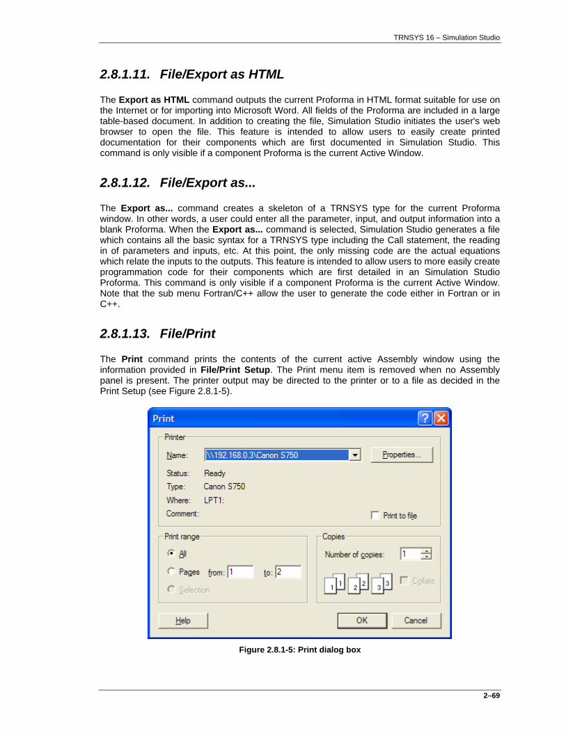
TRNSYS 16 – Simulation Studio
2–69
2.8.1.11. File/Export as HTML
The Export as HTML command outputs the current Proforma in HTML format suitable for use on the Internet or for importing into Microsoft Word. All fields of the Proforma are included in a large table-based document. In addition to creating the file, Simulation Studio initiates the user's web browser to open the file. This feature is intended to allow users to easily create printed documentation for their components which are first documented in Simulation Studio. This command is only visible if a component Proforma is the current Active Window.
2.8.1.12. File/Export as...
The Export as... command creates a skeleton of a TRNSYS type for the current Proforma window. In other words, a user could enter all the parameter, input, and output information into a blank Proforma. When the Export as... command is selected, Simulation Studio generates a file which contains all the basic syntax for a TRNSYS type including the Call statement, the reading in of parameters and inputs, etc. At this point, the only missing code are the actual equations which relate the inputs to the outputs. This feature is intended to allow users to more easily create programmation code for their components which are first detailed in an Simulation Studio Proforma. This command is only visible if a component Proforma is the current Active Window. Note that the sub menu Fortran/C++ allow the user to generate the code either in Fortran or in C++.
2.8.1.13. File/Print
The Print command prints the contents of the current active Assembly window using the information provided in File/Print Setup. The Print menu item is removed when no Assembly panel is present. The printer output may be directed to the printer or to a file as decided in the Print Setup (see Figure 2.8.1-5).
Figure 2.8.1-5: Print dialog box

TRNSYS 16 – Simulation Studio
2–70
2.8.1.14. File/Printer Setup
This command configures Simulation Studio to operate with the user’s printer device. Figure 2.8.1-6 depicts the Printer Setup box. The Printer Setup is the standard Windows Printer setup box. The printer device may be changed to another printer by selecting a new printer from the pull-down menu next to Name. Additional changes to the printer setup can be made by clicking on the Properties button.
Figure 2.8.1-6: The Printer Setup Box
2.8.1.15. File/Settings
This command allows the user to change the Simulation Studio and TRNSYS configuration. The following setup menu tabs are available:
2.8.1.15.1. FILE/SETTINGS/CONTROL CARDS This tab allows the user to set the default values for the Control Cards window such as default deck filename, default simulation times, etc (see Figure 2.8.1-7). Every value set in the Control Cards window can have its default value set here. Use the Assembly/Control Cards… menu to change the settings for the current project.

TRNSYS 16 – Simulation Studio
2–71
Figure 2.8.1-7: Control Cards Settings Tab
At the bottom of this window, it is possible to choose if TRNSED commands should be generated in the TRNSYS input file or not. An input file containing TRNSED commands can be used to create stand-alone applications from a simulation project with the help of the TRNSED program (see “Volume 7 TRNEDit: Editing the Input File and Creating TRNSED Applications” for more information). While selecting 'Write TRNSED commands' allows the user of the input file with TRNSED, this option will generate more CONSTANTS (one for each unlocked variable in the simulation project). These extra constants may cause huge simulations to run very slowly. The other option, 'Don’t write TRNSED commands', produces more legible input files. The default value is “Don’t write TRNSED commands”.
Another variable controls the writing of Simulation Studio Meta-commands in the TRNSYS input file. If this value is "True" (On), Simulation Studio Meta-Commands will be added to the TRNSYS input file. These commands are treated by TRNSYS like comments, i.e. they will not have any influence on the simulation. However, they allow Simulation Studio to better reconstruct a simulation project from a TRNSYS input file, using the File/Import function. This is useful for re-importing a modified TRNSYS Input file.
If Meta-commands are not present in the import file, Simulation Studio uses the ModelConfFile.conf file in the EXE directory to map UNIT declarations to PROFORMAs.

TRNSYS 16 – Simulation Studio
2–72
Figure 2.8.1-8: Project Settings Tab
2.8.1.15.2. FILE/SETTINGS/PROJECT The settings on this tab set the line colors for links (both with and without internal connections) and the color for when an item (link or component icon) is selected. This screen also allows the user to include additional standard layers. These layers are then available in the current Assembly panel as well as future projects. See the chapter on the Assembly Panel to learn more about using Layers within Simulation Studio to organize the viewing of component icons. To add a new Layer, type the desired name in the text box in the Layers: box, then select "Add" to include it in the main list of layers. The dimension of the project desktop can be specified in the Project size box in the lower left corner. It should be increased to add room for additional components.
The size of the icons in the Direct Access Toolbox can be set in the Icon size of Direct Access bar in the lower right corner. You may have to restart Simulation Studio for the new icons sizes to be active in the Direct Access Toolbox.
Autoscroll can be enabled/disabled for project or connection dialog using the check box at the bottom right
2.8.1.15.3. FILE/SETTINGS/DIRECTORIES The Directories tab allows the user to select directories and file names for launching and configuring various tools within Simulation Studio (see Figure 2.8.1-9). For example, you can

TRNSYS 16 – Simulation Studio
2–73
select a different editor than Notepad by changing the path and filename by the “editor” entry. Except for the editor where “Notepad.exe” can be specified, all path are relative to the Trnsys16 installation directory if the path does not start with a drive name or a “\”.
Figure 2.8.1-9: Directories Settings Tab
TRNSYS Application: The TRNSYS simulator used to run simulations
(TrnExe.exe), for example. Text Editor: The text editor used throughout the system; if this line
is left blank, the MS Windows Notepad will be used. Users are free to specify any text editor here or even a word processor.
TRNSED Application: The program file of the TRNSED front end program. PREP Application: The program file of the PREP program. TRNBUILD Application: The program file for the building edition. PREBID Application: The program file for the PREBID program.

TRNSYS 16 – Simulation Studio
2–74
SPREAD Application: The program file for the spreadsheet application used throughout the system; users may replace the default spreadsheet program delivered with Simulation Studio by any spreadsheet program such as Microsoft Excel.
FORTRAN Environment: The program file for the Fortran Development tool
used and provided separately by the user. C++ Environment: The program file for the C++ Development tool used
and provided separately by the user. Base Icon Folder: The directory in which the component icons are
located; this allows users to switch between different sets of component icons such as the DIN standard icons
Base Library Folder: The directory in which the component models are
stored; the direct access tree will use this directory to construct its structure.
2.8.1.15.4. FILE/SETTINGS/COMPILER This option allows users to specify the proper command line statements that will be run when the Simulation Studio menu commands Tools/Rebuild TRNSYS, and Tools/Execute User Command are chosen. The full command line statements, including path names and file extensions, should be entered in these fields as shown in Figure 2.8.1-10. The Rebuild TRNSYS command executes the command line in the box titled "Linker Command". It is intended to be the command which will rebuild the TRNSYS DLL (TRNDll.dll). For more information on compiling Fortran routines and rebuilding the TRNSYS DLL, refer to “Volume 8 – Programmers Guide”. The User Command field is intended as a convenient way to execute any desired program or batch file from Simulation Studio. If desired, the Rebuild TRNSYS command can be used for this purpose as well.
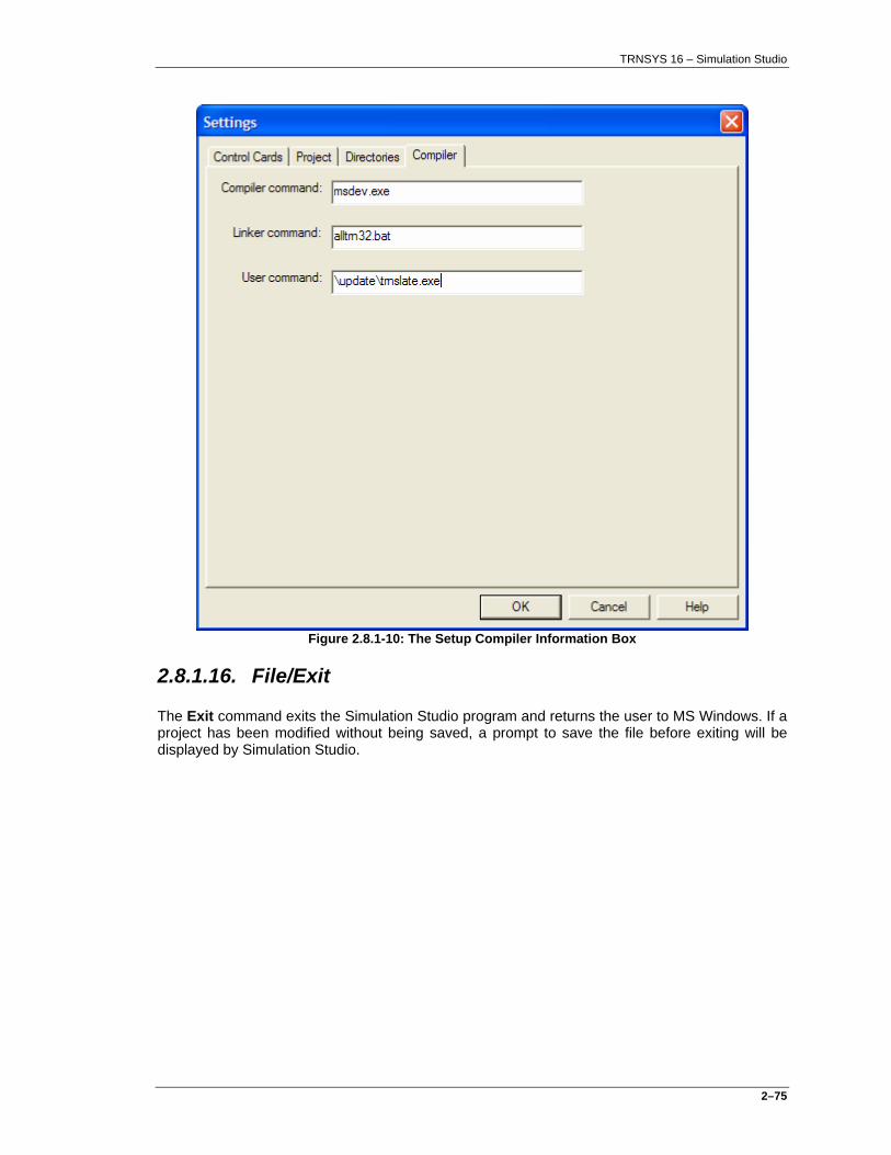
TRNSYS 16 – Simulation Studio
2–75
Figure 2.8.1-10: The Setup Compiler Information Box
2.8.1.16. File/Exit
The Exit command exits the Simulation Studio program and returns the user to MS Windows. If a project has been modified without being saved, a prompt to save the file before exiting will be displayed by Simulation Studio.

TRNSYS 16 – Simulation Studio
2–76
2.8.2. The edit menu
The Edit menu provides commands for cutting, copying and pasting text into and out of active windows and icons within the Assembly panel. The following is a description of the Edit menu commands and their function as shown in Figure 2.8.2-1.
Figure 2.8.2-1: The Edit Menu
2.8.2.1. Edit/Undo CTRL+Z
Undo will reverse the last several actions which was performed in the Assembly Panel. The Undo Button is not active while working in a Component Proforma.
2.8.2.2. Edit/Redo CTRL+Y
When the user uses the "Undo" command, actions that have been "Undone" can then be "Redone" using the "Redo" menu item.
TRNSYS 16 – Simulation Studio
2–77
2.8.2.3. Edit/Cut CTRL+X
Cut will remove selected text or an icon from the active window and place it in a storage location (the clipboard) from which it can be retrieved or restored with the Edit/Paste command. Text or icons may be selected (highlighted) by 'dragging' the mouse (i.e., holding the mouse button down while moving it to the new location) to form a rectangle around items to be selected.
2.8.2.4. Edit/Copy CTRL+C
The Copy command leaves the selected text or icon intact but places an exact copy of the text or icon into the clipboard. To place the copied text or icon into any other window, make that window active and choose the Edit/Paste command.
2.8.2.5. Edit/Paste CTRL+V
The Paste command inserts the previously selected text or icon from the clipboard into the active window at the current cursor position.
2.8.2.6. Edit/Delete DEL
The Delete command removes the selected text or icon from the window but does not put it into the clipboard. With the Delete feature, the selected text or icons cannot be pasted as it could have if the Cut or Copy commands had been chosen. Care should be taken, as the deleted items are not retrievable. The Delete command also works on "Links", the visible connection between links.
2.8.2.7. Edit/Replace
The Replace command allows the user to replace a current component on the Assembly panel with another component. The user should select a component already existing on the Assembly Panel. Then, select Edit/Replace which will bring up a dialog. From this dialog, the user should select another component. This new component will replace the existing component. The advantage of this method is that existing links will not be broken and the user does not need to re-connect as many links between components.
2.8.2.8. Edit/Update project
The Update project command allows the user to replace all of the current component on the Assembly panel with the latest version of the components accessible in the Access Tree toolbar. The advantage of this method are that the user only has to do this operation once for all of the components in the current project, as well as existing links will not be broken and the user does not need to re-connect as many links between components.

TRNSYS 16 – Simulation Studio
2–78
2.8.2.9. Edit/Properties...
The Properties... command opens up the "Component Properties" window for the currently selected component. This property window is shown below and allows you to modify every aspect of the component icon from the text properties to the position and size of the icon.
Figure 2.8.2-2: Component Properties Dialog Box
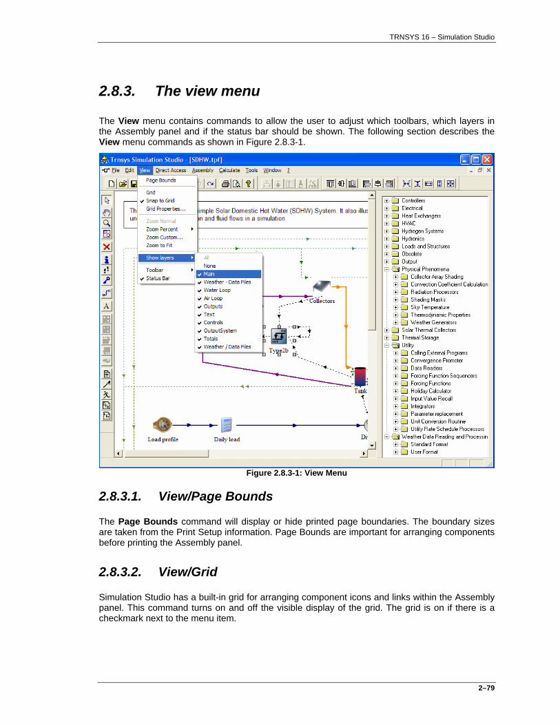
TRNSYS 16 – Simulation Studio
2–79
2.8.3. The view menu
The View menu contains commands to allow the user to adjust which toolbars, which layers in the Assembly panel and if the status bar should be shown. The following section describes the View menu commands as shown in Figure 2.8.3-1.
Figure 2.8.3-1: View Menu
2.8.3.1. View/Page Bounds
The Page Bounds command will display or hide printed page boundaries. The boundary sizes are taken from the Print Setup information. Page Bounds are important for arranging components before printing the Assembly panel.
2.8.3.2. View/Grid
Simulation Studio has a built-in grid for arranging component icons and links within the Assembly panel. This command turns on and off the visible display of the grid. The grid is on if there is a checkmark next to the menu item.

TRNSYS 16 – Simulation Studio
2–80
2.8.3.3. View/Snap to Grid
This command turns on and off the enforcement of the placement of components and links onto the grid points. If the Snap to Grid is on, then components and links can only be placed or moved to points on the grid. If off, components and links can be placed anywhere on the Assembly panel.
2.8.3.4. View/Grid Properties...
This command opens a dialog box that allows the user to modify all the grid properties including the grid spacing and the other grid menu items "Show Grid" and "Snap to Grid".
2.8.3.5. View/Zoom Normal
The Assembly panel can be magnified, or zoomed. The Zoom Normal menu item adjusts the size of the items in the Assembly panel to the default size.
2.8.3.6. View/Zoom Percent
The Zoom Percent menu opens up a submenu with several default percentage zoom values including 50%, 75%, 100%, and 200%.
2.8.3.7. View/Zoom Custom
The Zoom Custom menu opens up a small dialog box that allows the user to insert the precise desired magnification percentage.
2.8.3.8. View/Zoom to Fit
The Zoom To Fit menu magnifies or shrinks the Assembly panel items until they all fit within the visible window while maintaining the current proportions.
2.8.3.9. View/Show Layers
This command allows the user to select which component layers are currently displayed. Each component belongs to one or several layer(s) and is only displayed if one of these layers is being displayed. To use this menu item, select layers from the submenu. If the layer has a checkmark by the name, then it is being displayed. It is possible to turn off or on all the layers at once. There is more discussion about layers in the section concerning the Assembly Panel.
2.8.3.10. View/Toolbars
The Toolbars command will display or hide toolbars which are associated with different windows and can access quickly the same commands as are available on the pull down menu. The values chosen will be saved for the next use of Simulation Studio.
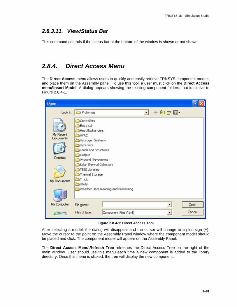
TRNSYS 16 – Simulation Studio
2–81
2.8.3.11. View/Status Bar
This command controls if the status bar at the bottom of the window is shown or not shown.
2.8.4. Direct Access Menu
The Direct Access menu allows users to quickly and easily retrieve TRNSYS component models and place them on the Assembly panel. To use this tool, a user must click on the Direct Access menu\Insert Model. A dialog appears showing the existing component folders, that is similar to Figure 2.8.4-1.
Figure 2.8.4-1: Direct Access Tool
After selecting a model, the dialog will disappear and the cursor will change to a plus sign (+). Move the cursor to the point on the Assembly Panel window where the component model should be placed and click. The component model will appear on the Assembly Panel.
The Direct Access Menu\Refresh Tree refreshes the Direct Access Tree on the right of the main window. User should use this menu each time a new component is added to the library directory. Once this menu is clicked, the tree will display the new component.

TRNSYS 16 – Simulation Studio
2–82
2.8.5. Assembly Menu
The Assembly main menu provides access to commands used within the Assembly Panel and its dialog windows. In general, this includes working with components, making and exploding macros and accessing the general control cards (see Figure 2.8.5-1).
Figure 2.8.5-1: Assembly Menu
2.8.5.1. Assembly/Insert New Equation
Because equations are so commonly used and are not really a component, equations are added to the assembly panel using their own menu item. The menu item places an equation icon on the assembly panel. The user can then double-click on this icon to create new equations. Once new equations are create, other components can be linked to the inputs and outputs of the equation component. See the Equation section in this manual for more information about adding Equations to the simulation.
2.8.5.2. Assembly/ Link Mode
This command is used in the process of creating output to input connections between two components. The user can click on this tool which will switch the cursor to Link Mode. Then,

TRNSYS 16 – Simulation Studio
2–83
when the user clicks on a component and then on a second component, a link is created between these two components. The user can also create links using the right mouse menu item “Start Link” when clicking on an existing component in the assembly panel.
2.8.5.3. Assembly/Add-Remove Trace
This command adds the TRNSYS Trace feature to all currently selected components. In addition, a small feet symbol appears near the icon to show that Trace is turned on for this component. To turn off the trace for a component: Select the component and click this command which will toggle off the Trace feature. Settings for Trace are contained in the Control Cards window.
2.8.5.4. Assembly/Lock-Unlock
The Assembly/Lock-Unlock menu command allows the creator of a project to lock certain components in the assembly panel. These locked components cannot be erased nor modified. When the entire component is locked, then all parameters and inputs internally are locked. This means that, if TRNSED commands are being written to the TRNSYS input file, they will not be included for this component.
2.8.5.5. Assembly/ Proforma...
The Proforma command opens up the window that contains the general Proforma for the component. The general Proforma contains information about the model and allows the user to access the source code of the component. See the manual section on Proformas for more information.
2.8.5.6. Assembly/ Variables...
The Variables command opens up the window that contains the parameters, inputs, outputs, derivatives, Special Cards, External Files and comments for a component. The user will first select the component of interest and then click on this menu command to open the window.
2.8.5.7. Assembly/ Open Macro
This command allows the user to access several components that are already contained in a macro component. To do this, the user should select a macro component. Then, click on this menu command or double-click on the macro model. The macro will open in a new assembly panel so that the components can be modified.
2.8.5.8. Assembly/ Close Macro
This command closes the assembly panel that is currently displaying the contents of a macro component.
2.8.5.9. Assembly/ Create Macro
This command allows the user to collect several components into a macro component. To do this, the user should select several components by clicking on each component while holding the

TRNSYS 16 – Simulation Studio
2–84
SHIFT key down. Then, click on this menu command. The selected components will be compressed into a single Macro item with the name highlighted for the user to enter the text of the name.
2.8.5.10. Assembly/Explode Macro
This command replaces an existing macro with the components contained inside this macro. The user should first select a macro on the Assembly panel and then click on this command.
2.8.5.11. Assembly/Save Macro...
This command saves a macro component so that it can be used in future projects. It is generally a good idea to save this macro component within the Base Library Folder directory tree so that the macro model is available within the Direct Access tool.
2.8.5.12. Assembly/Output Manager
This command opens the Output Manager dialog (see Figure 2.8.5-2), which allows the user to manage all outputs to files and plotters. On the left, all project components are displayed in a tree. On the right, all project printer and plotter are displayed.
Clicking on a component node will display its output variables and on a printer or plotter its input variables.
Displayed properties and available buttons are updated depending on which type of output component is selected.
2.8.5.12.1. CONNECT BUTTON
Just after selecting a valid output and input, clicking on this button ( ) in the middle of the dialog will add a new connection between the two components (the assembly panel will be updated in consequence).
2.8.5.12.2. REMOVE CONNECTION BUTTON
Removing an existing connection is available by clicking on this button ( ) after selecting a valid output and input connected variables.
2.8.5.12.3. ADD PLOTTER /PRINTER BUTTON
Printers and plotters can be added by clicking the Add Printer ( ) or Add Plotter button
( ).
2.8.5.12.4. PRINTERS AND PLOTTERS PROPERTIES Properties of printers and plotters can be modified on the right of the dialog:
• plotter properties: unit name, graph title, left axis properties, right axis properties and number of plots.
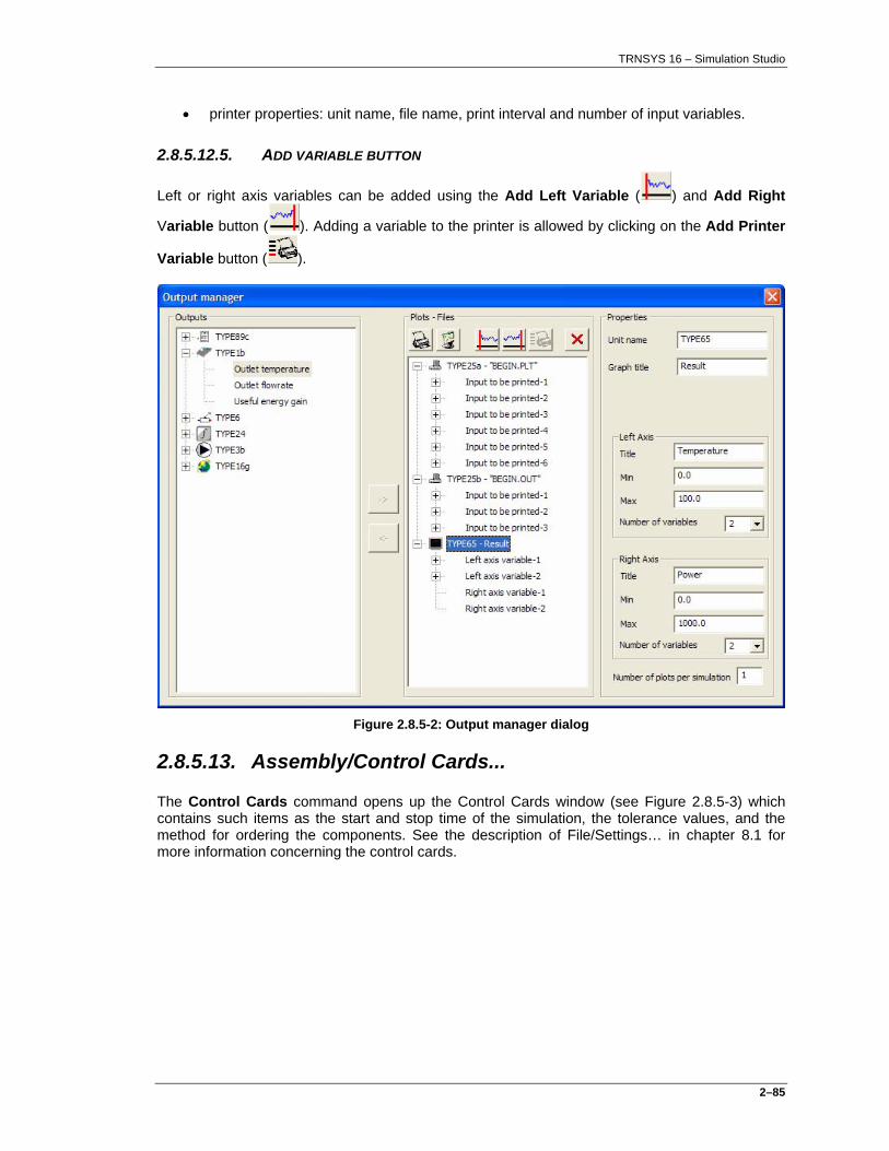
TRNSYS 16 – Simulation Studio
2–85
• printer properties: unit name, file name, print interval and number of input variables.
2.8.5.12.5. ADD VARIABLE BUTTON
Left or right axis variables can be added using the Add Left Variable ( ) and Add Right
Variable button ( ). Adding a variable to the printer is allowed by clicking on the Add Printer
Variable button ( ).
Figure 2.8.5-2: Output manager dialog
2.8.5.13. Assembly/Control Cards...
The Control Cards command opens up the Control Cards window (see Figure 2.8.5-3) which contains such items as the start and stop time of the simulation, the tolerance values, and the method for ordering the components. See the description of File/Settings… in chapter 8.1 for more information concerning the control cards.

TRNSYS 16 – Simulation Studio
2–86
Figure 2.8.5-3: Control Cards Window
2.8.5.14. Assembly/Diagram Image...
This command allows the user to modify the icon which is associated with the active project file. The icon bitmap will be opened in Microsoft Paint just as a component icon would be opened.
2.8.5.15. Assembly/Add Text...
This command adds text to the Assembly panel allowing the user to make comments to the project. This is useful for viewing and when printing projects. To use this option, click the Add Text command and then click on the Assembly Panel. This adds a box into which the user can type text. This text string will be added to every layer that is currently being displayed.
2.8.5.16. Assembly/Open in Spreadsheet
This command allows the user to automatically load the output of a Type 25 or Type 65 output file directly into the Spread program for easy graphical viewing. Simply select the icon which is associated with an output file and then click on this command. The Spread program will start up and open this file.

TRNSYS 16 – Simulation Studio
2–87
2.8.5.17. Assembly/Send To Layer
A component can belong to several layers at the same time. This command allows the user to move components to a new layer than it currently resides on. To use this menu item, select one or more components which should be added another layer. Then, click this menu item and select a layer name from the submenu which appears on the side. The components will be added a new layer and links will be moved or stretched accordingly. Note that additional layers can be defined in the File/Settings menu. There is more discussion about layers in the section concerning the Assembly Panel.
2.8.5.18. Assembly/Connections...
This command opens the currently selected link as if it had been double-clicked.
2.8.5.19. Assembly/Long Variable Names
This command modifies the way that Variable names are displayed in Macros. To change this, open one of the Variable tabs for a Macro model in the current assembly panel. Then, check/uncheck this menu item to modify the view of the variable names.

TRNSYS 16 – Simulation Studio
2–88
2.8.6. Calculate Menu
The Calculate menu offers choices for running the TRNSYS program as well as utilities for managing Fortran. The Calculate menu commands, as shown in Figure 2.8.6-1, are described in this section.
Figure 2.8.6-1: The Calculate Menu
2.8.6.1. Calculate/Create Input File
The Create Input File command creates the TRNSYS input file but does not start the simulation. The Create input file command is disabled unless the Assembly panel is in the front.
2.8.6.2. Calculate/Run Simulation The Run Simulation command calls the TRNSYS simulation program with the settings that have been stored in the File/Settings menu. The Run Simulation command is disabled unless the Assembly Panel is the active Window. This command may also be executed using the F8 key. Upon completion of the calculations, TRNSYS will tell the user the calculations are complete and ask if he would like to exit the program. Clicking “Yes” will return the user to the Simulation Studio program where the output may be viewed and results plotted, etc.

TRNSYS 16 – Simulation Studio
2–89
2.8.6.3. Calculate/Open
This command allows the user to easily access text files associated with the current project.
Calculate/Open/Input Text File
The Input Text File command opens the TRNSYS input file in the editor1. The file name of the Input file is shown in the menu as well. The input file shown will be the one which is generated from the active Assembly panel project.
Calculate/Open/List Text File
The List Text File command opens the TRNSYS list file in the editor1. The file name of the List file is shown in the menu as well. The list file shown will be the one which is generated by running the simulation in the active Assembly panel project.
Calculate/Open/External Files The External files command is used to open any of the other files associated with the current TRNSYS project. Simulation Studio searches the components in the project to see if they have any associated files (such as data files or output files). A list of these files is shown in the submenu to External Files. The user can select these files which will be opened in the editor.
1 The text editor is, by default, Microsoft Notepad. The user can change this to the editor of their choice, such as WinCommander. To do this, click on File/Settings/Directories menu item and change the path and file name for “editor”.

TRNSYS 16 – Simulation Studio
2–90
2.8.7. Tools menu
The Tools menu provides choices for various TRNSYS utility programs. The Tools menu commands, as shown in Figure 2.8.7-1, are described in this section.
Figure 2.8.7-1: The Tools Menu
2.8.7.1. Tools/Editor
This command initiates a user-designated text editing program which can be used to edit output files, etc.
2.8.7.2. Tools/Unit Dictionary
This command allows the user to view and modify items in the Unit Dictionary. The Unit Dictionary contains all the different dimensions (such as length) and units (such as meters). The user can create new dimensions or new units or change existing dimensions and units. The Unit Dictionary is described in detail later in this manual.

TRNSYS 16 – Simulation Studio
2–91
2.8.7.3. Tools/TRNBuild
This command initiates the TRNBuild program for use with Type 56, the multi-zone building model. Refer to the TRNBuild manual for details about the program. For ease of use, the TRNBuild directory in the File/Setup/Directories menu should be changed to Building\TRNBuild.exe before calling this program.
2.8.7.4. Tools/PREP
This command calls the PREP program, a wall/roof/partition transfer function generator for use with the single zone model, TRNSYS Type 19. Refer to the main TRNSYS reference manual for details about the PREP program. For ease of use, the PREP directory in the File/Setup/Directories menu should be changed to prep\prep.exe before calling this program.
2.8.7.5. Tools/SPREAD
This command calls the SPREAD program, a spreadsheet program for use with TRNSYS. The spreadsheet program is by default the Microsoft Excel spreadsheet program. The included spreadsheet program can be replaced by the user’s desired spreadsheet program by changing the setting in File/Settings/Directories.
2.8.7.6. Tools/TRNEdit
This command calls the TRNEdit program, a utility program for displaying TRNSYS input files with a modified look. TRNEdit is used for sharing TRNSYS simulations with non-TRNSYS users to allow them to do limited simulations. Please see the TRNEdit manual for more details.
2.8.7.7. Tools/Fortran Environment
This command calls the Fortran Compiler program which can be any Fortran compiler program. Examples would be Compaq Visual Fortran 6. The default value is "\Program Files\Microsoft Visual Studio\Common\MSDEV98\BIN\DFDEV.EXE"" which is the default location for the Compaq Visual Fortran.
2.8.7.8. Tools/C++ Environment
This command calls the C++ Compiler program which can be any C++ compiler program. Examples would be Visual Studio 7.0. The default value is "\Program Files\Microsoft Visual Studio\Common\MSDEV98\BIN\DFDEV.EXE"" which is the default location for the Visual Studio 7.0.
2.8.7.9. Tools/Rebuild TRNSYS
This command allows the user to create a new TRNSYS DLL. The Rebuild TRNSYS command executes the command line statement which has been entered as a Rebuild command in the File/Settings/Compiler setting.

TRNSYS 16 – Simulation Studio
2–92
2.8.7.10. Tools/Execute User Command
This command allows the user to execute any legitimate command line statement from the program. The desired command should be entered into the File/Settings/Compiler input box including path names and file extensions.
2.8.8. Windows menu
The Windows menu contains commands for manipulating and opening various windows existing in Simulation Studio. The following section describes the Windows menu commands as shown in Figure 2.8.8-1.
Figure 2.8.8-1: Windows menu
2.8.8.1. Windows/Cascade
The Cascade option will stack all open files so that a user can see the title bar of each file.
2.8.8.2. Windows/Tile
The Tile command will display all open files in a format where every file takes up a portion of the window environment.

TRNSYS 16 – Simulation Studio
2–93
2.8.8.3. Windows/Arrange Icons
When windows are minimized in Simulation Studio, they appear across the bottom of the screen. This command arranges the minimized window icons in a nice order.
2.8.8.4. Windows/Close All Windows
This command closes all open windows within the main window. If there are unsaved files, Simulation Studio will ask if they should be saved before they are closed.
2.8.8.5. Windows/List of Recent Files
A list of recently active windows is contained at the bottom of this menu. Any of these windows can be reopened with this menu.
2.8.9. Help Menu
The Help menu provides access to on-line help in a special help window. The help system provides information on many aspects of the Simulation Studio and TRNSYS programs. The following section describes the commands in the Help menu as shown in Figure 2.8.9-1.
Figure 2.8.9-1: The Help Menu

TRNSYS 16 – Simulation Studio
2–94
2.8.9.1. Studio/Help
This command shows the Simulation Studio help file. It is PDF document and will open separately in your Acrobat Reader application. You can navigate in the document by clicking in the Table of content. To move forward or backward through the help topics, click on the available buttons at the bottom. Additionally, users may press the F1 key at any time to receive context-sensitive help.
2.8.9.2. TRNSYS/Help
This command shows the TRNSYS help file. It is PDF document and will open separately in your Acrobat Reader application. You can navigate in the document by clicking in the Table of content. To move forward or backward through the help topics, click on the available buttons at the bottom. This file contains all other help file from the package. Each file is accessible from this index file.
2.8.9.3. About...
This command shows the About screen for Simulation Studio (Figure 2.8.9-2). This contains information about Simulation Studio, the version number and who the registered user is for this copy of Simulation Studio. Only the person or group indicated on this screen is allowed to use Simulation Studio. Any other users are using a pirated copy of Simulation Studio.
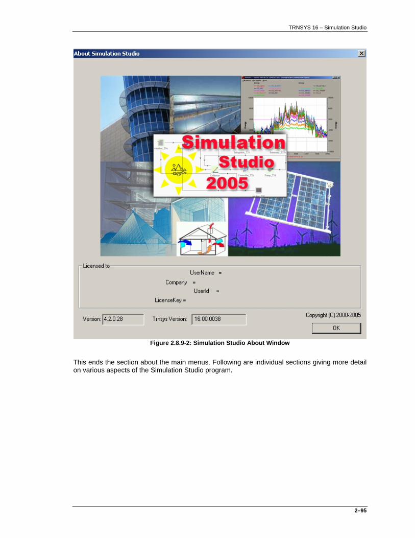
TRNSYS 16 – Simulation Studio
2–95
Figure 2.8.9-2: Simulation Studio About Window
This ends the section about the main menus. Following are individual sections giving more detail on various aspects of the Simulation Studio program.

TRNSYS 16 – Simulation Studio
2–96
2.9. Unit dictionary
The Unit Dictionary window (shown in Figure 2.8.9-1) is where users can obtain and specify unit and dimension information for the Simulation Studio program. The Unit Dictionary is accessed by clicking on Tools/Unit Dictionary menu item in the Main Simulation Studio window. The Unit Dictionary window is composed of a "Dimensions" list box, and a few buttons located on the right side of the window. The "Dimensions" list box contains the dimensions and base units that are currently contained in the unit dictionary. The "Dimensions" list box contains the names of the dimensions currently embedded in the Unit Dictionary program as well as their default SI unit. The Simulation Studio program will NOT have to be restarted in order for any changes made to the unit dictionary to take effect.
The menus of the User Dictionary will launch various applications contained in the unit dictionary program. A detailed description of the unit dictionary functions follows.
Figure 2.8.9-1: Unit Dictionary Window

TRNSYS 16 – Simulation Studio
2–97
Figure 2.8.9-2: Dimension properties Window
By selecting one of the dimensions and clicking edit, the Dimension Definition window will appear. This window allows the user to modify the name of the dimension, to modify the symbol of the dimension, to describe the dimension in base units, to add/modify/delete equivalent units for this dimension, and to describe the dimension. Selecting one of the equivalent units and clicking the Edit… button will bring up the Unit Definition window which is described in the next section. The Unit Definition window allows the user to modify the name of the unit, to modify the symbol of the unit, to supply multiplication and addition factors used to convert the unit to the default SI unit, and to describe the unit.

TRNSYS 16 – Simulation Studio
2–98
Figure 2.8.9-3: Unit Definition Window
2.9.1. Creating a New Dimension
The Add button in the main Unit Dictionary window opens the Dimensions window (Figure 2.8.9-2). The user can then edit this new dimension as they wish and it will be automatically added to the main window when the user clicks the OK button to leave the window.
2.9.2. Creating a New Unit
The button Add in the Dimensions window opens the Units window (Figure 2.8.9-3). The user can then edit this new unit as they wish and it will be automatically added to the Dimension definition window when the user clicks the OK button to leave the window.
2.9.3. To Delete a dimension or Unit
It is easy for the user to delete a dimension or unit in the unit dictionary. To delete a unit or dimension, click once on the name of the unit or dimension to be erased to select it. Then, click the Delete button which is next to the list box. A confirmation will appear prompting the user whether to delete the unit or dimension (Yes) or to cancel the operation (No). It is not possible to delete the base units or dimensions. For Simulation Studio purposes, the base units and dimensions are assumed to be:
• Temperature K
• Mass kg

TRNSYS 16 – Simulation Studio
2–99
• Atomic Weight mol
• Length m
• Time s
• Illumination cd
• Electric Current A
If a user could delete any of the base units and/or dimensions, it would no longer be possible to use some of the existing units and dimensions, or add units and dimensions to the unit dictionary program. Therefore, this is not allowed.
2.9.4. Unit Dictionary Example
Suppose Pressure had not been previously added to the unit dictionary and a user wished to create a model that required the specification of the pressure in kiloPascals (kPa). The steps required to add the pressure dimension and the kPa unit to the unit dictionary are described below.
1) Launch the Unit Dictionary application by clicking on the Tools/Unit Dictionary menu item in the main Simulation Studio window.
2) Click with the mouse on the Add button in the Unit Dictionary window. A blank Dimension window will open up.
3) Fill in the name, "Pressure", and a description of the new dimension; "Pressure is a measure of the force per unit area", for example.
4) Fill in the standard SI symbol for the unit of pressure. In this case, the standard unit for pressure is the Pascal which is commonly shown as "Pa". Note: kiloPascals (kPa) would not be an acceptable choice for the standard SI pressure unit since kPa is a direct multiple of Pa.
5) Convert Pascals to base units:
6) Pascal = Newton/square meter
= kilogram.meter/square second.square meter
= kilogram/square second/meter.
7) In this case the following text would be added to the "In base units" input box:
"kg/m/s/s"
8) The program will automatically format the text into the desired form. Make sure to use the correct symbols for the base units or the program will not accept the new dimension.
9) Note: At this stage, the new dimension has been added to the unit dictionary. The next steps will detail how to add a new unit, in this case kPa, to the unit dictionary.

TRNSYS 16 – Simulation Studio
2–100
10) Add a new unit by selecting the Add tool button in the Dimension window.
11) The Unit Definition window will appear similar to Figure 2.8.9-3.
12) Fill in the symbol for this unit, "kPa", and a description of the new unit; "kPa = kiloPascal = 1000 Pascals; a unit of pressure in the SI unit system", for example.
13) Fill in the conversion coefficients required to convert the base units of pressure (Pascals) to kiloPascals:
14) # Pa * 1 kPa/1000 Pa = # kPa
15) In this case, "0.001" would be input to the multiplication field and "0.0" would be input to the addition field.
16) Click OK to exit the Unit window and then OK to exit the Dimension window. The new dimension and unit are now saved to the Simulation Studio program and may be used in the component models.
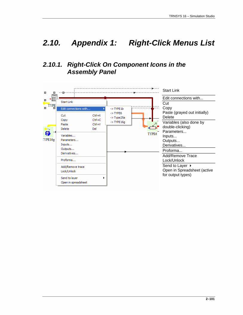
TRNSYS 16 – Simulation Studio
2–101
2.10. Appendix 1: Right-Click Menus List
2.10.1. Right-Click On Component Icons in the Assembly Panel
Start Link
Edit connections with... Cut Copy Paste (grayed out initially) Delete Variables (also done by double-clicking) Parameters... Inputs... Outputs... Derivatives... Proforma... Add/Remove Trace Lock/Unlock Send to Layer Open in Spreadsheet (active for output types)

TRNSYS 16 – Simulation Studio
2–102
2.10.2. Right-Click On Macros in Assembly Panel Window
(all as above) + Open Macro Explode Macro Save Macro

TRNSYS 16 – Simulation Studio
2–103
2.10.3. Right-Click On Blank Spot in Assembly Panel Window
Paste Undo Redo Page Bounds Grid Snap to Grid Grid Properties... Zoom Show Layers Control Cards... Run Simulation Save Project... Print...
2.10.4. Right-Click On Links in Assembly Panel Window
Delete Connections... (also done by double-clicking) User-defined Path (with a check box)

TRNSYS 16 – Simulation Studio
2–104
2.11. Appendix 2: How to use the plug-in
The Simulation Studio plug-in technology allows you to add your own user friendly application to Simulation Studio to edit the component’s properties. Just create your application and write in Simulation Studio the name of your executable file. Then your application is launched instead of the old classical dialog box.
2.11.1. The plug-in technology
Write an executable containing the dialog you want to be displayed using any programming language. The installation directory of the executable is independent of the Simulation Studio installation directory and the name of the executable is independent of the type name.
We have chosen an EXE file format instead of a DLL, because using an EXE file is more flexible for the user. He doesn't have to match with a specific API and to call a method with thousands of parameters. Moreover, an EXE file can be easily written any programming language (C++, java or VB for example), but it will be much more difficult to write a DLL in some of these languages (such as JAVA).
This executable will read values from an exchange file in order to be initialized, and write modified values to the same exchange file.
The exchange file name will be automatically generated and unique for each instance of type. It will be passed as an argument to the executable. So, the user will just have to check in the main method of his EXE for the argv[1] argument which will contain the name of the exchange file including the whole path. Thus, there is no problem for editing two units at the same time, because exchange files names will be different.

TRNSYS 16 – Simulation Studio
2–105
2.11.2. Simulation Studio settings
A new option has been added to the control cards of Simulation Studio (see Figure 2.11.2-1). Click “File/Settings” in the menu.
The following dialog appears:
Figure 2.11.2-1: Plug-in control card
One of the last options called “Automatically launch plug-in” is set to “false” by default. If you want your plug-in to be automatically launched when you double click on a component, set this option to “true”. In all cases, if the plug-in name is not valid, the old dialog is opened by default.
This option can also be set for each project. Then, when a project is opened, click on “Assembly/Control Cards…”. You can change the same option as before, except that the value (true or false) can be different for each project and saved with the project.

TRNSYS 16 – Simulation Studio
2–106
2.11.3. How to connect your plug-in to Simulation Studio
To allow Simulation Studio to launch your plug-in when you double click on a component, you have to specify the name of the plug-in executable file.
Either you specify the name in the Proforma itself or in the component properties. If you specify the name in the Proforma, each component based on this Proforma will know the name.
2.11.3.1. Specify the plug-in path name in the Proforma.
Open the Proforma. An edit box appears in the “Description” tab.
Just type the name of your plug-in including the whole path in the edit box “Plug-in path”. If the path starts with “.”, Simulation Studio will look for the plug-in in the installation directory of Trnsys16 and complete automatically the name.
Then, when you will add a component based on this Proforma to your project, it will know the name of the plug-in application to launch.

TRNSYS 16 – Simulation Studio
2–107
2.11.3.2. Specify the plug-in path name in the component properties.
Open the component properties. A new edit box appears in the “Comment” tab.
Just type the name of your plug-in including the whole path in the edit box «Plug-in path».
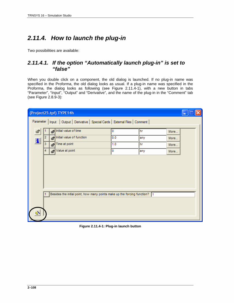
TRNSYS 16 – Simulation Studio
2–108
2.11.4. How to launch the plug-in
Two possibilities are available:
2.11.4.1. If the option “Automatically launch plug-in” is set to “false”
When you double click on a component, the old dialog is launched. If no plug-in name was specified in the Proforma, the old dialog looks as usual. If a plug-in name was specified in the Proforma, the dialog looks as following (see Figure 2.11.4-1), with a new button in tabs “Parameter”, “Input”, “Output” and “Derivative”, and the name of the plug-in in the “Comment” tab (see Figure 2.8.9-3):
Figure 2.11.4-1: Plug-in launch button

TRNSYS 16 – Simulation Studio
2–109
Figure 2.11.4-2: Plug-in path
The button doesn’t appear if the plug-in name is not valid, i.e. the file specified by this name doesn’t exist on the hard drive.
So if you modify the plug-in name, each time you go to another tab, the file name is checked and the button appears or disappears depending on the file name validity.

TRNSYS 16 – Simulation Studio
2–110
Now, either you work as usual and then you close the dialog, or you click on the new button which launches the plug-in, taking the name of the file containing all the component values as a parameter (the exchange file). When the plug-in is launched, the old dialog is closed.
In this example, “FunctionEditor.exe” is launched opening the file with the values of the “type14h” component (see Figure 2.11.4-3).
Figure 2.11.4-3: FunctionEditor as a plug-in example
The plug-in window can be iconified, maximized and resized. If you double click on a component which has its plug-in window already open, it is displayed in front of all opened windows even if it was iconified or hidden.
The plug-in window is always visible on top of Simulation Studio, just like the ‘old‘ dialogs.
Now, when you close the plug-in, the values are read back by Simulation Studio from the exchange file, taking into account the new values modified by the plug-in (note: the exchange file is erased when the plug-in is closed).
2.11.4.2. If the option “Automatically launch plug-in” is set to “true”
The behavior is quite the same as before, except that if a plug-in name was specified in the Proforma, the component creation or in the component properties, the old dialog is not opened and the plug-in is directly launched after double clicking on the component.

TRNSYS 16 – Simulation Studio
2–111
2.11.5. Plug-in with Equations
To specify the plug-in path for an equation, open the equation properties. It looks as following, with an edit box called “Plug-in path”. You can type the plug-in path, for example “notepad.exe” can be used. When the plug-in path name is valid, i.e. the file exists on the hard drive, a new button appears (see Figure 2.11.5-1).
Figure 2.11.5-1: Equation plug-in path

TRNSYS 16 – Simulation Studio
2–112
Then, click on the button to launch the plug-in. If notepad is used as a plug-in, it looks like the Figure 2.11.5-2: the exchange file has been opened as a simple text file in notepad. Equations can be modified in the notepad.
Figure 2.11.5-2: Notepad as equation plug-in
If the option “Automatically launch plug-in” of Simulation Studio is “true”, the plug-in is directly launched instead of the old dialog when you double click on an equation.

TRNSYS 16 – Simulation Studio
2–113
2.11.6. The exchange file
The exchange file is the file passed as a parameter to the plug-in, allowing the plug-in to read the values of the component. This file is read back and erased by Simulation Studio when the plug-in is closed. The content of the file is a little bit different if the plug-in is associated to a component or to an equation.
2.11.7. The exchange file for component ! File generated by Simulation Studio 4 ! Copyright CSTB 2003 TypeNumber UnitNumber TypeName ! [TypeNumber UnitNumber TypeName] INPUTS Number_Of_Cycles ! [Number of cycles] Number_of_cycle_1_repetition First_Var_Cycle_1 Last_Var_Cycle_1 ! [CycleRepetition FirstVar LastVar] Number_of_cycle_2_repetition First_Var_Cycle_2 Last_Var_Cycle_2 ! [CycleRepetition FirstVar LastVar] … Number_of_cycle_n_repetition First_Var_Cycle_n Last_Var_Cycle_n ! [CycleRepetition FirstVar LastVar] Number_Of_Inputs ! [Number of variables] Input_1 ! Name_1 | Unit_1 | Min_1 | Max_1 | ConnectionState Input_2 ! Name_2 | Unit_2 | Min_2 | Max_2 | ConnectionState … Input_n ! Name_n | Unit_n | Min_n | Max_n | ConnectionState (Idem for PARAMETERS and DERIVATIVES) EXTERNAL_FILES Number_Of_FileName File_Name_1 ! Question_1 File_Name_2 ! Question_2 … File_Name_n ! Question_n SPECIAL_CARDS Number_Of_Cards Card_1 ! Question_1 Card_2 ! Question_2 … Card_n ! Question_n COMMENT Number_Of_Comment_Line Comment_Line_1 Comment_Line_2 ... Comment_Line_n
In line “Input_1 ! Name_1 | Unit_1 | Min_1 | Max_1 | ConnectionState”, the value of Input_1 and Unit_1 are the values converted to the Proforma default value.
For example, if an input is a temperature given in °C in the Proforma and given in K in the type, it will be converted to °C in the exchange file.
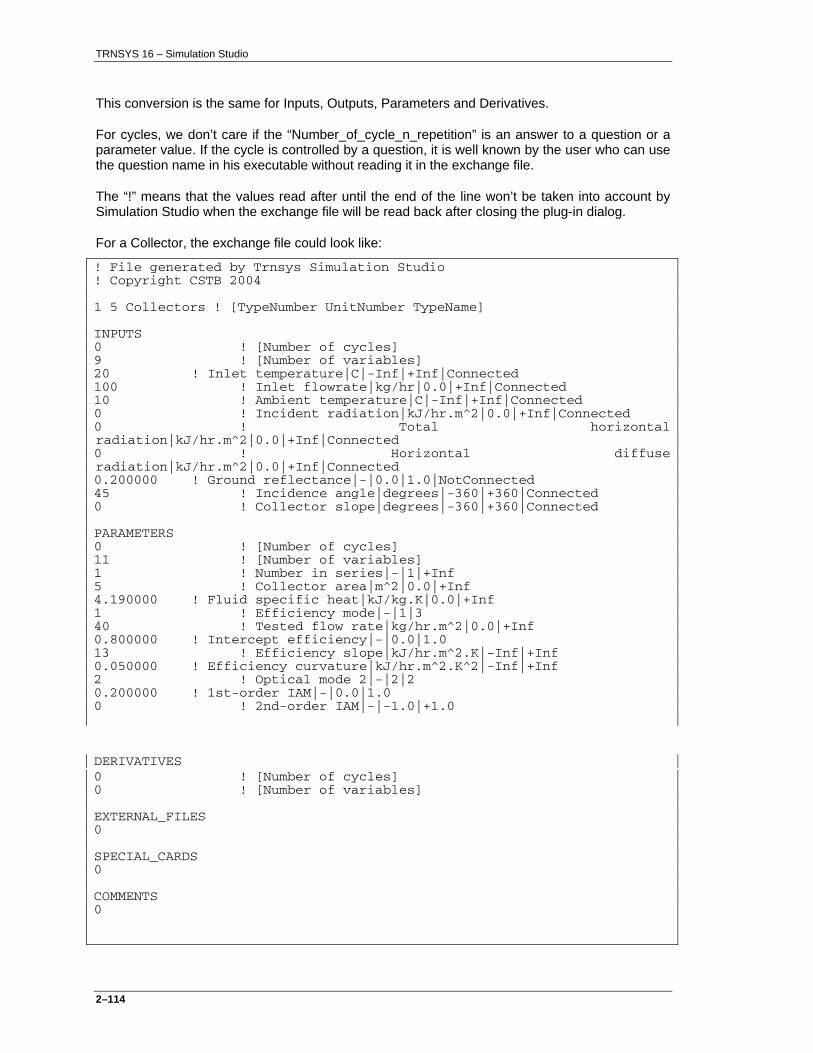
TRNSYS 16 – Simulation Studio
2–114
This conversion is the same for Inputs, Outputs, Parameters and Derivatives.
For cycles, we don’t care if the “Number_of_cycle_n_repetition” is an answer to a question or a parameter value. If the cycle is controlled by a question, it is well known by the user who can use the question name in his executable without reading it in the exchange file.
The “!” means that the values read after until the end of the line won’t be taken into account by Simulation Studio when the exchange file will be read back after closing the plug-in dialog.
For a Collector, the exchange file could look like:
! File generated by Trnsys Simulation Studio ! Copyright CSTB 2004 1 5 Collectors ! [TypeNumber UnitNumber TypeName] INPUTS 0 ! [Number of cycles] 9 ! [Number of variables] 20 ! Inlet temperature|C|-Inf|+Inf|Connected 100 ! Inlet flowrate|kg/hr|0.0|+Inf|Connected 10 ! Ambient temperature|C|-Inf|+Inf|Connected 0 ! Incident radiation|kJ/hr.m^2|0.0|+Inf|Connected 0 ! Total horizontal radiation|kJ/hr.m^2|0.0|+Inf|Connected 0 ! Horizontal diffuse radiation|kJ/hr.m^2|0.0|+Inf|Connected 0.200000 ! Ground reflectance|-|0.0|1.0|NotConnected 45 ! Incidence angle|degrees|-360|+360|Connected 0 ! Collector slope|degrees|-360|+360|Connected PARAMETERS 0 ! [Number of cycles] 11 ! [Number of variables] 1 ! Number in series|-|1|+Inf 5 ! Collector area|m^2|0.0|+Inf 4.190000 ! Fluid specific heat|kJ/kg.K|0.0|+Inf 1 ! Efficiency mode|-|1|3 40 ! Tested flow rate|kg/hr.m^2|0.0|+Inf 0.800000 ! Intercept efficiency|-|0.0|1.0 13 ! Efficiency slope|kJ/hr.m^2.K|-Inf|+Inf 0.050000 ! Efficiency curvature|kJ/hr.m^2.K^2|-Inf|+Inf 2 ! Optical mode 2|-|2|2 0.200000 ! 1st-order IAM|-|0.0|1.0 0 ! 2nd-order IAM|-|-1.0|+1.0
DERIVATIVES 0 ! [Number of cycles] 0 ! [Number of variables] EXTERNAL_FILES 0 SPECIAL_CARDS 0 COMMENTS 0

TRNSYS 16 – Simulation Studio
2–115
The exchange file for an equation
! File generated by IISiBat 4 ! Copyright CSTB 2003 UnitNumber EquationName ! [UnitNumber TypeName] INPUTS Number_Of_Inputs | Name_1 ! ConnectionState | Name_2 ! ConnectionState … | Name_n ! ConnectionState OUTPUTS Number_Of_Outputs Output_1 | Name_1 ! ConnectionState Output_2 | Name_2 ! ConnectionState … Output_n | Name_n ! ConnectionState
Everything after ‘!’ can be skipped, Simulation Studio will add it back next time the file is passed to the EXE.
For an Equation, the exchange file could look like:
! File generated by IISiBat 4 ! Copyright CSTB 2003 16 Efficiencies! [UnitNumber TypeName] INPUTS 8 |IColl_d!Connected |QuColl_d!Connected |QDHW_d!Connected |QAux_d!Connected |IColl!Connected |QuColl!Connected |QDHW!Connected |QAux!Connected OUTPUTS 4 QuColl_d / (5*IColl_d+1e-6)|EtaColl_d!Connected 1 - ( QAux_d / (QDHW_d + 1e-6) )|FSol_d!Connected QuColl / (5*IColl+1e-6)|EtaColl!Connected 1 - ( QAux / (QDHW+ 1e-6) )|FSol!Connected

TRNSYS 16 – Simulation Studio
2–116
2.12. Appendix 3: How to use the Wizard
2.12.1. Description
The wizard is launched after clicking in the main window on File\New or on the New ( ) button.
The dialog as shown in Figure 2.12.1-1 is then displayed:
Figure 2.12.1-1: The wizard dialog
First of all, an item must be selected in the list on the left (New Component, Empty Project, Solar hot water system, Building project (multizone), Building Project (simplified) ).

TRNSYS 16 – Simulation Studio
2–117
2.12.2. Multizone Building project step by step
2.12.2.1. Step 1/10: Selecting the project type
Figure 2.12.2-1: Selecting the project type
Once the right item is selected in the list (i.e. Building Project (multizone)), clicking on the Next button ( ) will go to next step.
The rest of this explanation shows the Building project (multizone) wizard, because it is the most complex one.

TRNSYS 16 – Simulation Studio
2–118
2.12.2.2. Step 2/10: Drawing the floor plan
Figure 2.12.2-2: Drawing the floor plan
To add a zone to the building, click on the left grid. Each black square represents a zone. At the same time, the wizard will automatically compute the adjacencies between added zones and display the list on the right.
Once the floor plan is drawn, clicking on the next button will go to next step.
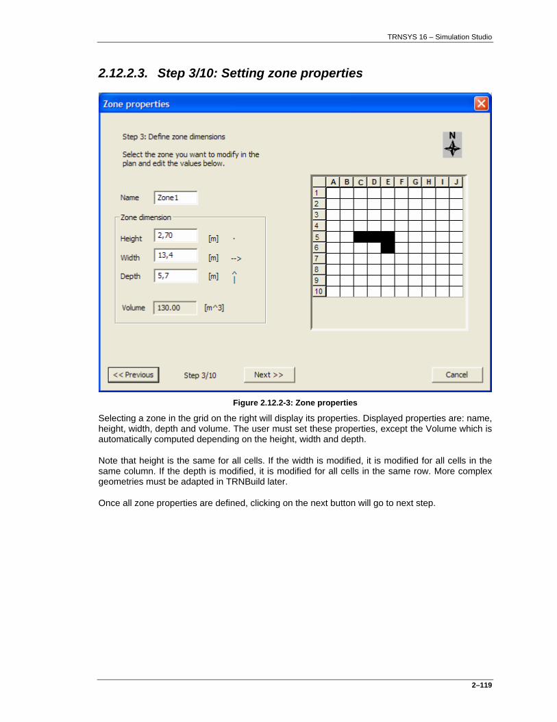
TRNSYS 16 – Simulation Studio
2–119
2.12.2.3. Step 3/10: Setting zone properties
Figure 2.12.2-3: Zone properties
Selecting a zone in the grid on the right will display its properties. Displayed properties are: name, height, width, depth and volume. The user must set these properties, except the Volume which is automatically computed depending on the height, width and depth.
Note that height is the same for all cells. If the width is modified, it is modified for all cells in the same column. If the depth is modified, it is modified for all cells in the same row. More complex geometries must be adapted in TRNBuild later.
Once all zone properties are defined, clicking on the next button will go to next step.
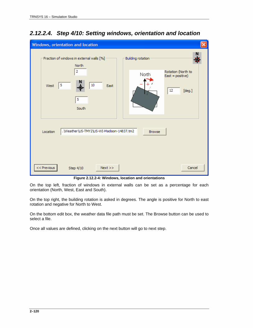
TRNSYS 16 – Simulation Studio
2–120
2.12.2.4. Step 4/10: Setting windows, orientation and location
Figure 2.12.2-4: Windows, location and orientations
On the top left, fraction of windows in external walls can be set as a percentage for each orientation (North, West, East and South).
On the top right, the building rotation is asked in degrees. The angle is positive for North to east rotation and negative for North to West.
On the bottom edit box, the weather data file path must be set. The Browse button can be used to select a file.
Once all values are defined, clicking on the next button will go to next step.

TRNSYS 16 – Simulation Studio
2–121
2.12.2.5. Step 5/10: Infiltration and ventilation
Figure 2.12.2-5: Infiltration and ventilation
On the top left, infiltration for all zones must be set as a leakage in 1/h.
Mechanical and natural ventilation can be added by checking the corresponding check boxes. Depending on the selection, more or less boxes are displayed and must be set. Activating these options will create more complex simulation projects, adding components as required.
For the mechanical ventilation, the rate must be set in 1/h. Two values are asked, one for periods where the building is occupied and another for periods where the building is unoccupied. A default schedule defining these periods is applied and can be adapted in TRNBuild later.
Also the humidity of supply air in percentage and the supply temperature in degree C are asked.
Finally, at the bottom, natural ventilation properties are defined. On the left, the natural ventilation rate is given, in 1/h. On the right, additional dependant temperature dependant ventilation can be defined. If this option is checked, additional ventilation will be simulated as soon as the temperature defined in ‘ventilation start’ is reached. On the other hand, this additional ventilation will stop if the temperature drops below the value defined under ‘Ventilation stop’.
Once all values are defined, clicking on the next button will go to next step.

TRNSYS 16 – Simulation Studio
2–122
2.12.2.6. Step 6/10: Heating and Cooling
Figure 2.12.2-6: Heating and cooling
In this step, the characteristics of the heating and cooling equipment built into PREBID can be defined. Although the settings defined here apply to all zones, separate heating and cooling types are defined. This allows the user to easily adapt the heating and cooling characteristics of each zone separately in TRNBuild later. The cooling set point temperature can be defined by the user (in °C) or defined as depending on the ambient temperature. In this second case, temperature at which cooling is to start will ‘follow’ the ambient temperature using the formula T_Cool = (T_Ambient + 49) /3, but not exceed 27 degrees nor fall below 25 degrees. An example is shown below. This formula can be adapted in the Simulation Studio’s Assembly Panel later.
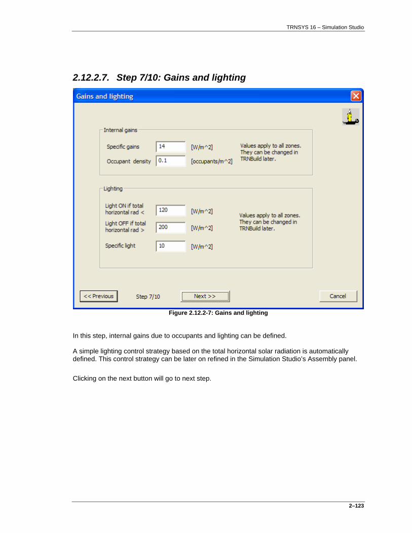
TRNSYS 16 – Simulation Studio
2–123
2.12.2.7. Step 7/10: Gains and lighting
Figure 2.12.2-7: Gains and lighting
In this step, internal gains due to occupants and lighting can be defined. A simple lighting control strategy based on the total horizontal solar radiation is automatically defined. This control strategy can be later on refined in the Simulation Studio’s Assembly panel.
Clicking on the next button will go to next step.

TRNSYS 16 – Simulation Studio
2–124
2.12.2.8. Step 8/10: Fixed shading
Figure 2.12.2-8: Fixed shading
This step allows to define fixed shading elements (overhangs and wing walls) for each of the four main orientations of the building. The user must click on the orientation (North, East, South or West) for which he wished to modify the fixed shading. Then, fixed shading can be activated for the selected orientation by checking the ‘Active’ checkbox. A given orientation can have no fixed shading, an overhang, a wing wall or both, depending on the status of the checkboxes in the lower part of the window. The receiver dimensions (window height and width) apply to all shading elements in this orientation. Once all orientations are defined, the user can ‘walk through’ the settings by successively selecting all orientations again, to check that the settings are correct.
Clicking on the next button will go to next step.

TRNSYS 16 – Simulation Studio
2–125
2.12.2.9. Step 9/10: Movable shading
Figure 2.12.2-9: Movable shading
This step allows to define fixed shading elements (such as stores or blinds) for each of the four main orientations of the building. The user must click on the orientation (North, East, South or West) for which he wished to modify the movable shading. Then, movable shading can be activated for the selected orientation by checking the ‘Active’ checkbox. Moveable shading for a given orientation is characterized by the total radiation thresholds for which the element will be opened or closed, as well as the ‘Maximum shading’ settings, which define the element’s characteristics in case it is closed. Once all orientations are defined, the user can ‘walk through’ the settings by successively selecting all orientations again, to check that the settings are correct.
Clicking on the next button will go to next step.
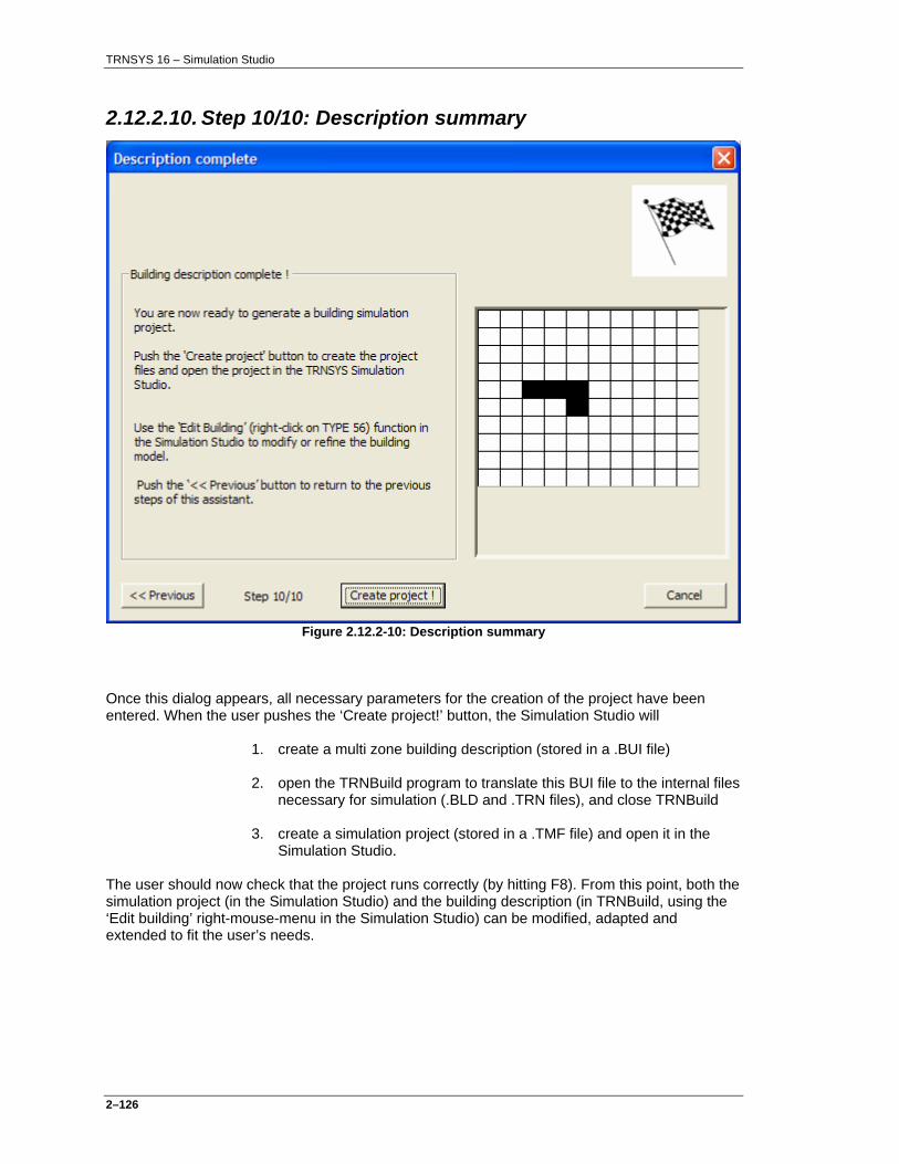
TRNSYS 16 – Simulation Studio
2–126
2.12.2.10. Step 10/10: Description summary
Figure 2.12.2-10: Description summary
Once this dialog appears, all necessary parameters for the creation of the project have been entered. When the user pushes the ‘Create project!’ button, the Simulation Studio will
1. create a multi zone building description (stored in a .BUI file)
2. open the TRNBuild program to translate this BUI file to the internal files necessary for simulation (.BLD and .TRN files), and close TRNBuild
3. create a simulation project (stored in a .TMF file) and open it in the Simulation Studio.
The user should now check that the project runs correctly (by hitting F8). From this point, both the simulation project (in the Simulation Studio) and the building description (in TRNBuild, using the ‘Edit building’ right-mouse-menu in the Simulation Studio) can be modified, adapted and extended to fit the user’s needs.