Using the latest ILI technologies to identify pipeline ...
15
Using the latest ILI technologies to identify pipeline pilferage by Ben Corlett 1 and Andrea Bologna 2 1 BHGE, Cralington, UK 2 TECMA Srl, Milan, Italy Technology for Future and Ageing Pipelines Conference Het Pand, Gent, Belgium 11-12 April, 2018 Organized by Lab. Soete and Tiratsoo Technical and supported by Clarion Technical Conferences The European Pipeline Research Group PRCI and Pigging Products & Services Association
Transcript of Using the latest ILI technologies to identify pipeline ...
Using the latest ILI technologies to identify pipeline pilferage
by Ben Corlett1 and Andrea Bologna2 1 BHGE, Cralington, UK
2 TECMA Srl, Milan, Italy
Technology for Future and
Ageing Pipelines Conference
Het Pand, Gent, Belgium
11-12 April, 2018
Organized by
Lab. Soete
and Tiratsoo Technical
and supported by Clarion Technical Conferences
The European Pipeline Research Group PRCI
and Pigging Products & Services Association

Technology for Future and Ageing Pipelines Conference, Gent, April 2018
2
Proceedings of the Technology for Future and Ageing Pipelines Conference. Copyright ©2018 by Lab. Soete, Tiratsoo Technical (a division of Great Southern Press), Clarion Technical Conferences, and the author(s). All rights reserved. This
document may not be reproduced in any form without permission from the copyright owners.

Technology for Future and Ageing Pipelines Conference, Gent, April 2018
3
Using the latest ILI technologies to identify pipeline pilferage
LLEGAL TAPPING AND PRODUCT theft is an increasingly significant threat to operators of refined product pipelines. Illegal tapping can cause a number of significant challenges to pipeline integrity such as: damage to external pipe wall and coating; a related introduction of
unknown risk of delayed failure due to stress raisers within the pipe wall and, most significantly; the direct and uncontrolled release of product without warning. As operators strive to find an effective early warning system that will provide alerts as pipelines are encroached upon, alternative approaches are required to assist in the location, and identification, of both existing, and new, illegal tap attempts. An existing pipeline inspection technology, with a proven track record of accurate location of illegal tap locations, is In-line Inspection (ILI) – specifically Magnetic Flux Leakage (MFL) tools. This paper looks at the various theft inspection solutions developed and implemented by Baker Hughes, a GE company (BHGE) and its partner company TECMA Srl (Tecma). It begins with a review of how ILI technology can be used to provide a reliable theft inspection service including test verification. This is followed by several different case studies showing how MFL tools have been used to successfully identify illegal tap sites. These case studies include results of ILI runs conducted in Europe using different MFL tools and techniques.
Introduction to illegal tapping The extent of, severity, and risk of pipeline product theft is a major concern to the oil and gas industry, and the worldwide community. The techniques being utilised are becoming more sophisticated as, in many cases, thieves use specialist equipment and industry knowledge to steal large quantities of refined products from pipelines. Pilferage activities, by tapping into pipelines, can cause significant environmental and commercial consequences, potentially leading to pipeline ruptures, potential human casualties, destruction of property, and damage to the environment [1,2]. Product thefts have steadily increased on UK and European pipeline networks since late 2013, with “one theft a week being detected in the UK in 2014” [1]. Furthermore, thieves are becoming more proficient and use specially-designed equipment to monitor whether the pipeline is running or not, its flow speed and product, so that they only steal the more saleable liquids from multi-product pipelines [1,2]. As operators strive to find an effective early warning system that will provide alerts as pipelines are encroached upon, alternative approaches are required to assist in the location and identification of both existing and new illegal tap attempts. An existing pipeline inspection technology, with a proven track record of accurate location of illegal tap locations, is In-line Inspection (ILI) – specifically Magnetic Flux Leakage (MFL) tools. This paper looks at the various theft inspection solutions developed and implemented by Baker Hughes, a GE company (BHGE) and its partner company TECMA Srl (Tecma). It begins with a review of how ILI technology can be used to provide a reliable theft inspection service including test verification. This is followed by several different case studies showing how MFL tools have been used to successfully identify illegal tap sites. These case studies include results of ILI runs conducted in Europe using different MFL tools and techniques.
Background to MFL MFL is a non-destructive In-line Inspection technique that has been widely used for 4 decades to inspect for the condition of oil and gas pipelines, usually to identify corrosion sites or weak points in the pipe wall. BHGE has two types of MFL-based inspection vehicles: one which imposes an axial magnetic field (MagneScanTM and CPIGTM inspection systems), parallel to the pipe flow direction; and one which imposes
I

Technology for Future and Ageing Pipelines Conference, Gent, April 2018
4
a magnetic field (TranScanTM inspection system), around the pipe wall circumference. The applications of MFL technology have been developed and utilised by BHGE, and its partner company Tecma, to become a valuable inspection method in the identification and reporting of Illegal taps. The most utilised technology platforms for this purpose are MagneScan and CPIG, however, BHGE has also employed TranScan, in a unique case, which will be described later. The basics During an MFL inspection, permanent magnets attached to brushes on the vehicle induce a strong, localised magnetic field, from the north to the south poles, axially through the pipe wall. A ring of primary sensors, positioned between the two sets of magnets, record the magnetic flux in the pipe wall as the inspection vehicle travels through the pipeline. The magnetic saturation of the pipe wall remains constant and undisturbed in an area with no features or fittings, i.e. plain pipe. Any variation from plain pipe, such as in the form of a reduction in metal or additional ferrous material close to the pipe wall, changes the induced magnetic field in the wall at that location (See Figure 1). The primary sensors detect these variations in magnetic flux and record its location and orientation in the pipeline. Using MFL to identify illegal taps The success of an inspection process relies on the enabling technology of the inspection tool, the capabilities and resolution of the sensors on the tool, and on validated and detailed interpretation processes of the resultant sensor data for the features of interest. From the perspective of being identified by an MFL inspection, illegal taps can be categorised in two ways: those that have a ferrous component, such as a steel full circular fitting, or welded attachment and; those that are non-ferrous, such as an attachment or component that is made from a non-magnetic material, for example, plastic. By categorising illegal taps in these two ways, BHGE has employed the principal detection capabilities of MFL technology to identify and locate illegal taps, and has had the application of this technology verified in practice. Identifying ferrous illegal taps The most common form of illegal tap, and also the easiest to identify using MFL technology, are those with a ferrous component. Examples of these include, steel full circular sleeves or clamps, welded offtakes, or attachments (see Figure 2). Illegal taps with an additional ferrous component create a decreased signal response in the primary sensors when applied to the magnetic field. The amount of magnetic flux that can be accommodated by the pipe wall and additional material is increased compared to plain pipe, and less flux is ‘leaked’ from the pipeline at that location. This additional ferrous signal is identified and classified during the analysis of the inspection data. The data can then be compared to known features and fittings on the pipeline, either from historic pipeline inspections or from client supplied pipeline records, such as maps, design drawings or repair information, to determine if the identified feature may potentially be an illegal tap. The feature is highly likely to be an illegal tap if it is new compared to a previous inspection or is not known to the pipeline operator. Once a new fitting is identified, and if pipeline mapping data is available, the location of the fitting can be viewed in geographic visualisation software such as Google EarthTM to further assess its likelihood to be an illegal tap and give greater confidence, as well as more detailed location information, when reporting the feature to the pipeline operator. Illegal taps located close to field boundaries and near tree lines is a common trend observed in the inspection data.
Technology for Future and Ageing Pipelines Conference, Gent, April 2018
5
Identifying non-ferrous illegal taps Illegal taps with no ferrous components are naturally more difficult to identify using MFL technology. However, the method for identifying these features relies on the MFL tool’s primary function – the ability to detect metal loss – and, in particular, the enhanced ability of the fourth generation MagneScan tool (New MagneScan) and its proven capability to accurately detect pinholes. In cases of a reduction in metal in the pipe wall, such as an area of corrosion, the amount of magnetic flux the pipe wall can support is reduced, causing an increased amount of flux to leak out at this weaker point. This increase in flux leakage is detected by the primary sensors, and the area of metal loss can be identified during the signal data analysis. This principle of identifying metal loss can be applied to the detection of illegal taps without a ferrous component. Although a non-ferrous attachment cannot be detected by the primary sensors, they can detect the drill hole from which the product is being released. Figure 3 shows a drill hole that was identified on an operational pipeline. Drill hole dimensions used to steal product from a pipeline typically fall into the Pipeline Operators Forum’s (POF) metal loss classification of pinholes, defined as having a length < 1A and a width < 1A (if wall thickness less (t) < 10mm, then A = 10mm, if wall thickness (t) ≥ 10mm then A = t) [3]. The enhanced resolution of BHGE’s new generation MFL technology provides the ability to detect through-wall pinholes down to 2mm in diameter [4,5,6]. This detection capability has been verified in papers by Bluck [5]; and Santamaria and Bluck [6]. The implications of this for pilferage detection means the precision of the MFL vehicle has the ability to identify non-ferrous illegal taps with drill holes down to this diameter. A further advantage of this detection capability means it can detect non-through-wall drilling attempts caused by pilferage activity. Figure 4 show an excavated illegal tap with three unsuccessful non-through-wall drilling attempts. During data processing, a software algorithm identifies individual areas of metal loss. This could be an anomaly, such as corrosion, or a manufacturing fault or, as described above, could be a potential drill hole. Each metal loss signal in the data is ‘boxed’. Magnetic signal parameters are assigned to the box and, from these, the physical dimensions of the feature on the surface of the pipeline are predicted. One of these dimensions is depth. In order to quickly identify potential illegal taps during the pilferage analysis, a screening pass of the boxes with a depth greater than 50% of wall thickness is initially carried out. When a metal loss feature with a predicted depth greater than 50% is identified, the signal is compared to historic inspection data, if available, to determine if it is new and, if so, whether it is a potential illegal tap. For completeness, a full pass of the inspection data is also carried out, to identify any other metal loss features that are visually significant and new compared to historic inspection data. If pipeline mapping data is available, the location of a significant or likely drill hole feature is viewed in Google EarthTM, to further assess its likelihood to be a pilferage site. Verifying the identification of illegal taps To verify the MFL tool’s ability to detect real pilferage features, BHGE and Tecma have developed a plan to periodically perform pull-through testing of discovered illegal taps, following a number of instances on pipelines in Italy since 2001. A recent example of one of these pull-through tests was completed in 2015. Tecma supplied a 10” test spool with four types of ferrous attachment, consisting of three tap features and one full circular clamp fitting, as shown in Figure 5. The spool also contained three through-wall drill holes, ranging from 10mm to 5mm in diameter, simulating non-ferrous illegal taps, as shown in Figure 6. These attachments and drill holes were typical of the type of features typically used to steal product from a number of Italian pipelines [7]. Multiple pull-through tests were carried out using BHGE’s 10” New MagneScan inspection vehicle at different velocities to assess the tool’s ability to detect the features. All seven features were identified during

Technology for Future and Ageing Pipelines Conference, Gent, April 2018
6
each pull-through run. Figure 7 shows the signal data from one of the pull-through runs, which is annotated to highlight the seven features, as below:
Cast iron tap fitted over a drill hole, with a non-ferrous, full circular clamp fitting. Ferrous attachment fitted over a drill hole. Three through-wall drill holes: 5mm, 7mm and 10mm (from left to right). Ferrous attachment fitted over a drill hole. Ferrous attachment protruding into the pipeline (Causing sensors to be lifted off from the pipe
wall). The results of these pull-through tests demonstrate the MagneScan vehicle is proficient in detecting genuine pilferage attempts and techniques. Performing pull-through tests, such as these, not only validate the tool’s capability to detect illegal taps, but also gives further support material to help train data analysts to identify and classify them in operational run data. There is no predictable pattern in detecting instances of pilferage, given the range of materials, fitting types, and sophisticated techniques used by thieves. Therefore, it is important to continuously verify the tool’s ability to identify genuine features, when discovered on operational pipelines, and to continuously update analysts’ catalogues to aid recognition.
Real-life examples of illegal taps: a series of case studies Case Study 1 – stopping theft through accurate identification and reporting This case study illustrates MagneScan’s accuracy in identifying illegal taps and how it can quickly produce useful information for locating and reporting illegal taps. The case also highlights the need for developments in security and monitoring to better protect refined product pipelines.
In 2014, a farmer and a storage unit operator separately reported to police suspicious events that led to the discovery of two illegal taps. Detectives described the case as a sophisticated operation including one tap linked to a tank holding around 30,000 L of stolen product. The pipeline owner took immediate action, mobilising its engineering and environmental experts to assess the two sites and collaborating with local authorities and police to minimise any risk to local residents and nature. They then asked if BHGE could help determine if there were any other illegal taps in the line. Using a MagneScan tool, BHGE ran an in-line inspection (ILI), comparing results to another MFL inspection completed in 2006. Within seven days, the data analysis was completed and a highly-practical Excel-based Change Report was produced. Its quick-read format gave precise location details about newly-detected anomalies. Nine illegal taps were identified along the >150 km line. On receiving the Change Report, the owner shut down the pipeline and began cutting out spools for repair and replacement. While the value of stolen product was estimated at over $70,000 US, the costs of potential asset and environmental damage could have reached well into the millions if the illegal fittings had failed before being safely remediated. Six months later, BHGE conducted another inspection on the same pipeline and found several new illegal tapping sites. The discovery has inspired an increased focus on security and monitoring on their pipeline network.[8]
Figure 8 shows one of the new features identified in the MFL data, and excavated illegal tap it corresponds to.

Technology for Future and Ageing Pipelines Conference, Gent, April 2018
7
Case Study 2 – thieves developing techniques to avoid visual detection by pipeline operators This case study shows how thieves are becoming more sophisticated and audacious in their attempts to avoid discovery by going to extreme lengths to hide their illegal activities from visual detection by the pipeline operator and members of the general public.
The majority of illegal taps, identified on recent BHGE inspections in Europe, are located in areas where there is surrounding cover, such as in hedgerows and tree lines. This is most likely due to the criminals not wanting to raise suspicion when installing and accessing the tap, but also them attempting to hide the tap from being visually discovered, either from examination by the operator, or accidentally by a member of the general public. In 2016 BHGE carried out a pilferage inspection on a European pipeline using the MagneScan vehicle. This particular pipeline had been targeted multiple times by thieves in the past, and the operator decided to carry out regular ILI inspections to identify changes and new features between consecutive inspections. A number of new features were detected and reported during the analysis, but one location exemplifies the extreme lengths thieves will go to, to avoid visual detection. Two attachments were identified under a pipeline casing, near to a river crossing. These attachments were new compared to the previous inspection, carried out in 2015, as shown in figure 9. Investigation by the pipeline operator confirmed these features were illegal taps, and the excavation highlighted the elaborate attempts of the thieves to disguise their illegal activity from visual discovery by the pipeline operator or members of the public. Figure 10 shows a man-hole used to access an underground section of the pipeline. A section of the pipeline casing had been cut away as shown in figure 11. Figures 12 and 13 show the illegal attachments welded on the pipeline underneath the casing.
Despite the thieves’ elaborate attempts to avoid detection, the obvious indications between the two inspection data sets allowed the pipeline operator to find these illegal taps, which may have gone undetected through visual pipeline examination. The implications of this case study highlight the needs for technical pipeline inspections, such as the ILI methods being discussed in this paper by BHGE, to identify hidden pipeline threats. Case Study 3 – thieves developing techniques to avoid technical detection by pipeline inspection companies This case study shows how, with historic inspection data, even well disguised illegal taps can be identified. It also demonstrates how thieves are developing cunning techniques to avoid technical detection by pipeline inspection companies.
In some cases, illegal taps stand out during data analysis. The taps are isolated, away from other pipeline fittings and, given the rather crude nature of the tap itself, are not visually similar to legitimate offtakes on the pipeline, and so can easily be distinguished. However, in other cases, thieves are becoming increasingly sophisticated in their attempts to avoid technical detection by pipeline inspection companies. One trend observed in BHGE inspections has been thieves installing illegal taps in locations close to other, genuine pipeline fittings. This is so the illegal fittings do not appear out of place under detection by a pipeline inspection company, and so are misclassified as legitimate fittings. In a recent inspection carried out by BHGE in a European pipeline, three offtakes were identified in a pipe spool adjacent to an above-ground valve station. These offtakes blended in well with other legitimate pipeline fittings in the area but, nevertheless, were noticeable new additions to the pipeline, because a previous inspection had been carried just one year prior.

Technology for Future and Ageing Pipelines Conference, Gent, April 2018
8
BHGE immediately prepared dig sheets, with detailed location information, to notify the pipeline operator of these new offtake-like features. Following investigation by the operator, these features were confirmed to be three illegal taps on the pipeline. During the investigation of these illegal taps, the operator also discovered that another offtake in this area, previously assumed to be legitimate, was also a well disguised illegal tap. This illegal fitting had gone undetected during the analysis of the first-time inspection, because it did not look out of place in its close proximity to the valve station and other similar legitimate fittings.
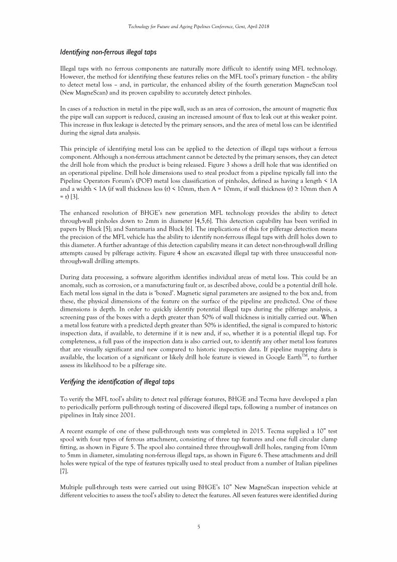
Figure 14 shows the signal data recorded by the MagneScan inspection tool. It highlights the change between the two inspections, and also indicates the previously detected, but not identified, illegal tap, discovered during the excavation. The implications of this case study are the need for analysts to develop a suspicious mind and for inspection companies to correlate inspection data with their own pipeline design and layout information. Case study 4 - identifying illegal taps using TranScan: a unique case Traditionally a MagneScan vehicle has been used to identify illegal taps. This unique case study explains how BHGE has also completed runs with the purpose of identifying illegal taps using one of its alternative MFL vehicles – the Transverse Field Inspection (TFI) vehicle (TranScan). Background to TranScan The principles of a TranScan (TFI) inspection are similar to a MagneScan inspection in that a magnetic field is induced into the pipe wall and primary sensors, positioned in between the magnets, record the magnetic flux leakage. However, the direction in which the magnetic field is imposed is different in the two technologies. While the MagneScan vehicle induces an axial magnetic flux field, parallel to the pipe wall, the TranScan vehicle, induces the magnetic field around the circumference of the pipe, as shown in Figure 15. In general, reporting specification terms, inducing the magnetic field circumferentially allows the TFI vehicle to detect narrow axial defects and axial cracks, which is a limitation of Axial MFL technology. Identifying illegal taps using TranScan
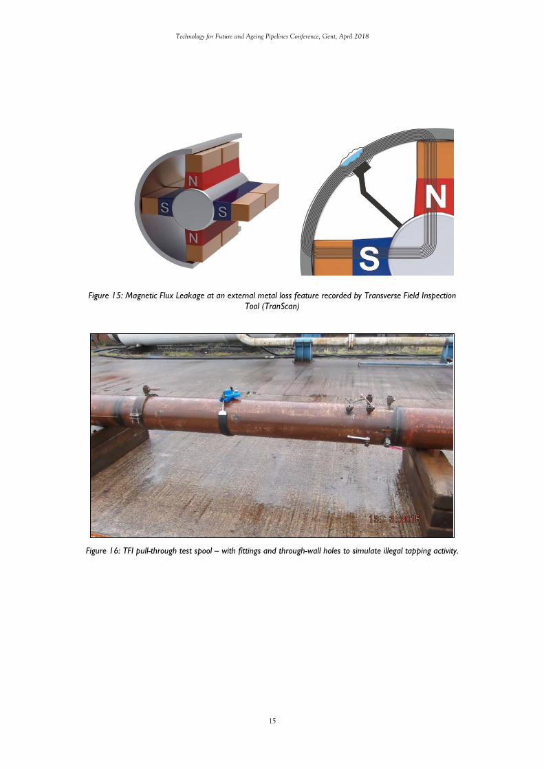
Following the success of the MagneScan’s ability to identify illegal taps, BHGE was contracted by a European operator to undertake pull-through testing of its 12” TranScan vehicle. The operator’s strategy for crack detection on their pipeline network required TFI inspections, but there was also a need for illegal tap detection. The purpose of these pull-through tests was not to confirm the detection capability of the TFI inspection vehicle, but to investigate if it could be used to detect tapping points attached to a test spool, with the aim to reduce the overall number of runs required by the operator. In March 2015, five pull-through runs were completed on a blind test spool with multiple tap-like fittings, and through-wall holes, at various orientations. All fittings were designed to be similar to the illegal taps previously discovered on the operator’s pipeline network. These included fittings that were welded onto and screwed into the test spool and those with through-wall holes, as well as a clamp, isolated drill holes and a fully circumferential ‘saddle’ fitting (see Figure 16).
The following observation were drawn for the analysis of the TranScan pull-through data:
1. All the tapping attachments were detected on each of the five of the pull-through runs. 2. The ferrous part of the saddle was detected on all runs, but, as expected, a non-ferrous, stainless
steel band was not visible in the inspection data. 3. The TFI inspection vehicle detected two 3.5mm diameter through holes on each of the five pull-
through tests. 4. The clamp fitting was detected on all five pull-through runs, the additional material around the
bolted flanges gave a significant indication in the inspection data. An additional attachment

Technology for Future and Ageing Pipelines Conference, Gent, April 2018
9
welded to the clamp at the 12 o’clock orientation was not visible in the data, this is due to the combined test spool wall thickness, clamp thickness and attachment being well above the TFI inspection vehicle specification.
The results of the pull-through tests concluded the TranScan tool can detect ferrous attachments similar to the ones already discovered on the operator’s network, and the vehicle is capable of detecting through-wall drill holes down to at least 3.5mm diameter, in the 5.9mm wall thickness test spool. This confirmed the overall aim of the pull-through tests: Illegal Tap detection could be incorporated into a TFI inspection, and the number of runs required by the operator was halved.[9] Following the successful pull-through tests, BHGE carried out five TFI pipeline inspections, using the TranScan technology. As well collecting data in order to carry out a comprehensive TFI inspection, the technology also confirmed there were no illegal taps on the pipeline network.
Conclusions This paper has looked at the various theft inspection solutions developed and implemented by Baker Hughes, a GE company (BHGE) and its partner company TECMA Srl (Tecma). It began with a review of how ILI technology can be used to provide a reliable theft inspection service including test verification, in the form of pull-through testing. This was followed by several case studies showing how the BHGE MFL tools have been used to successfully identify illegal tap sites on operational pipelines, and a unique case study, explaining how a different MFL tool – the TranScan – has been tested and employed to inspect a pipeline network for potential pilferage activity. These case studies illustrate MFL Technology’s accuracy in identifying illegal taps and how it can quickly produce useful information for locating and reporting them. They also highlight the need for: developments in security and monitoring on pipeline networks; continued visual and technical pipeline inspections; and stress the importance of vigilance as thieves develop sophisticated and cunning techniques to avoid detection.
References
1. Lock, A. (2017). The risks of pipeline product theft. [online] World Pipelines. Available at: https://www.worldpipelines.com/special-reports/09032017/the-risks-of-pipeline-product-theft/ [Accessed 13 February 2018]
2. Corner, E. (2015). Intelligent pigs: an evolution. [Online] World Pipelines. Available at: https://www.worldpipelines.com/special-reports/15052015/intelligent-pigs-an-evolution/ [Accessed 13 February 2018]
3. Pipeline Operators Forum (POF). (2016). Specifications and Requirements for In-Line Inspection of Pipelines, Version 2016. [Online] Available at: https://www.pipelineoperators.org/downloads-links/ [Accessed 12 Feb 2018]
4. Cribbs, S., Robinson, A. (2013). 6 inch MFL4 pull through in 5.6mm wt. Pinhole study. Internal BHGE study. Unpublished.
5. Bluck, M. (2014). Advancements in the Detection and Sizing of “Pinhole” Metal Loss in Onshore and Offshore Pipeline. In: Pigging Products & Services Association (PPSA) Technical Seminar. Aberdeen. Available at: https://ppsa-online.com/papers/14-Aberdeen/2014-10-PII-slides.pdf [Accessed 09 Feb 2018]
6. Santamaria, W., Bluck, M. (2014). Advancements in the Detection & Sizing of “Pinhole” Metal Loss. In: IPC 2014-33128, 10th International Pipeline Conference. Calgary: doi:10.1115/IPC2014-33128 Available at: http://proceedings.asmedigitalcollection.asme.org/proceeding.aspx?articleid=2022652 [Accessed 09 Feb 2018]

Technology for Future and Ageing Pipelines Conference, Gent, April 2018
10
7. Bologna, A. (2016). The Threat of Unidentified Pilferage. In: PII Pipeline Solutions Pipeline Technical Forum. Maastricht.
8. GE Oil and Gas (2015). Inspecting pipeline and foiling theft with MagneScan data. [Online] PII Pipeline Solutions. Available at: https://www.geoilandgas.com/sites/geog/files/magnescan-pipeline-inspection-data-prevents-fluid-theft-case-study.pdf [Accessed 10 February 2018]
9. Cribbs, S. (2015). TFI Tap Detection Technical Note. Internal BHGE study. Unpublished.

Technology for Future and Ageing Pipelines Conference, Gent, April 2018
11
Figure 1: Magnetic Flux Leakage at an external metal loss defect (Primary Sensors) recorded by axial magnetic flux tool
Figure 2: (Left) Typical example of a full circular clamp fitting with an attachment used for pilferage. (Right) Welded attachment identified on an operational pipeline
Figure 3: Example of a drill hole used to release product from an operational pipeline.

Technology for Future and Ageing Pipelines Conference, Gent, April 2018
12
Figure 4: Example of an excavated illegal tap and three non-through-wall drilling attempts.
Figure 5: 10” Pull-through test spool, with four attachments to simulate ferrous illegal taps.
Figure 6: Drill holes, 10mm, 7mm and 5mm in diameter to simulate non-ferrous illegal taps.

Technology for Future and Ageing Pipelines Conference, Gent, April 2018
13
Figure 7: MagneScan pull-through signal data of the 10” Tecma test spool.
Figure 8: MagneScan inspection data at location of new feature and corresponding tap feature discovered after excavation.
Figure 9: MagneScan inspection data - 2016 vs 2015 - showing 2 ‘new’ attachments

Technology for Future and Ageing Pipelines Conference, Gent, April 2018
14
Figure 10: Man-hole access point. Figure 11: Section of pipeline casing cut by thieves to gain access to the pipeline.
Figure 12 and 13: Two illegal taps identified on pipeline under pipeline casing
Figure 14: MagneScan inspection data, annotated to highlight changes and fittings between two consecutive inspections. (Top) Previous inspection. (Bottom) Most recent inspection.
Technology for Future and Ageing Pipelines Conference, Gent, April 2018
15
Figure 15: Magnetic Flux Leakage at an external metal loss feature recorded by Transverse Field Inspection Tool (TranScan)
Figure 16: TFI pull-through test spool – with fittings and through-wall holes to simulate illegal tapping activity.