Using the Architecture Tradeoff Analysis Method … · The system, called the Common Avionics...
31
Using the Architecture Tradeoff Analysis Method SM (ATAM SM ) to Evaluate the Software Architecture for a Product Line of Avionics Systems: A Case Study Mario Barbacci Paul Clements Anthony Lattanze Linda Northrop William Wood July 2003 Architecture Tradeoff Analysis Initiative Unlimited distribution subject to the copyright. Technical Note CMU/SEI-2003-TN-012
Transcript of Using the Architecture Tradeoff Analysis Method … · The system, called the Common Avionics...
Using the Architecture Tradeoff
Analysis MethodSM (ATAMSM) to
Evaluate the Software
Architecture for a Product Line
of Avionics Systems:
A Case Study Mario Barbacci Paul Clements Anthony Lattanze Linda Northrop William Wood July 2003 Architecture Tradeoff Analysis Initiative Unlimited distribution subject to the copyright.
Technical NoteCMU/SEI-2003-TN-012
The Software Engineering Institute is a federally funded research and development center sponsored by the U.S. Department of Defense.
Copyright 2003 by Carnegie Mellon University.
NO WARRANTY
THIS CARNEGIE MELLON UNIVERSITY AND SOFTWARE ENGINEERING INSTITUTE MATERIAL IS FURNISHED ON AN "AS-IS" BASIS. CARNEGIE MELLON UNIVERSITY MAKES NO WARRANTIES OF ANY KIND, EITHER EXPRESSED OR IMPLIED, AS TO ANY MATTER INCLUDING, BUT NOT LIMITED TO, WARRANTY OF FITNESS FOR PURPOSE OR MERCHANTABILITY, EXCLUSIVITY, OR RESULTS OBTAINED FROM USE OF THE MATERIAL. CARNEGIE MELLON UNIVERSITY DOES NOT MAKE ANY WARRANTY OF ANY KIND WITH RESPECT TO FREEDOM FROM PATENT, TRADEMARK, OR COPYRIGHT INFRINGEMENT.
Use of any trademarks in this report is not intended in any way to infringe on the rights of the trademark holder.
Internal use. Permission to reproduce this document and to prepare derivative works from this document for internal use is granted, provided the copyright and “No Warranty” statements are included with all reproductions and derivative works.
External use. Requests for permission to reproduce this document or prepare derivative works of this document for external and commercial use should be addressed to the SEI Licensing Agent.
This work was created in the performance of Federal Government Contract Number F19628-00-C-0003 with Carnegie Mellon University for the operation of the Software Engineering Institute, a federally funded research and development center. The Government of the United States has a royalty-free government-purpose license to use, duplicate, or disclose the work, in whole or in part and in any manner, and to have or permit others to do so, for government purposes pursuant to the copyright license under the clause at 52.227-7013.
For information about purchasing paper copies of SEI reports, please visit the publications portion of our Web site (http://www.sei.cmu.edu/publications/pubweb.html).
CMU/SEI-2003-TN-012 i
Contents
About the Technical Note Series on Business and Acquisition Guidelines ....v
Abstract..............................................................................................................vii
1 Introduction ..................................................................................................1
2 Context for the Architecture Evaluation .....................................................2 2.1 Software Architecture ............................................................................2 2.2 The TAPO Organization.........................................................................3 2.3 The CAAS .............................................................................................4
3 The ATAM ......................................................................................................6
4 The Evaluation of the CAAS Software Architecture...................................9 4.1 Background ...........................................................................................9 4.2 Business and Mission Drivers................................................................9 4.3 Architectural Approaches.....................................................................11 4.4 Utility Tree ...........................................................................................12 4.5 Scenario Generation and Prioritization ................................................14 4.6 Overview of the Analysis Process........................................................15 4.7 Post-ATAM Activities............................................................................16
5 Conclusions................................................................................................17 5.1 Benefits ...............................................................................................17 5.2 Summary.............................................................................................18
References .........................................................................................................19

ii CMU/SEI-2003-TN-012

CMU/SEI-2003-TN-012 iii
List of Tables
Table 1: Utility Tree for the Availability Quality Attribute.......................................14
Table 2: Brainstormed Scenarios from Step 7.....................................................15

iv CMU/SEI-2003-TN-012

CMU/SEI-2003-TN-012 v
About the Technical Note Series on Business and
Acquisition Guidelines
The Product Line Systems Program at the Software Engineering Institute (SEISM) is publishing a series of technical notes designed to condense knowledge about architecture tradeoff analysis practices into a concise and usable form for the Department of Defense (DoD) acquisition manager and practitioner. This series is a companion to the SEI series on product line acquisition and business practices.
Each technical note in the series will focus on applying architecture tradeoff analysis in the DoD. Our objective is to provide practical guidance to early adopters on ways to integrate sound architecture tradeoff analysis practices into their acquisitions. By investigating best commercial and government practices, the SEI is helping the DoD to overcome challenges and increase its understanding, maturation, and transition of this technology.
Together, these two series of technical notes will lay down a conceptual foundation for DoD architecture tradeoff analysis and product line business and acquisition practices. Further information is available on the SEI’s Product Line Systems Program Web page at <http://www.sei.cmu.edu/activities/plp/plp_init.html>.
SM Software Engineering Institute is a service mark of Carnegie Mellon University.

vi CMU/SEI-2003-TN-012

CMU/SEI-2003-TN-012 vii
Abstract
The quality of a software-intensive system depends heavily on the system’s software architecture. When used appropriately, software architecture evaluations can have a favorable effect on a delivered or modified government system. This technical note describes the application of the Architecture Tradeoff Analysis MethodSM (ATAMSM) to an Army avionics system acquisition. A government–contractor team is developing the Common Avionics Architecture System (CAAS) for a family of U.S. Army Special Operations helicopters. This technical note presents the contextual background about the software architecture, the organization, and the system being evaluated. It also provides a general overview of the ATAM process, describes the application of the ATAM to the CAAS, and presents important results and benefits.

viii CMU/SEI-2003-TN-012
CMU/SEI-2003-TN-012 1
1 Introduction
Because software architecture is a major determinant of software quality, it follows that software architecture is critical to the quality of any software-intensive system. For a Department of Defense (DoD) acquisition organization, the ability to evaluate software architectures before they are realized in finished systems can substantially reduce the risk that the delivered systems will not meet their quality goals.
Over the past several years, the Software Engineering Institute (SEISM) has developed the Architecture Tradeoff Analysis MethodSM (ATAMSM) and validated its usefulness in practice [Clements 02b, Kazman 00]. This method not only permits evaluation of specific architectural quality attributes (e.g., modifiability, performance, security, and reliability) but also engineering tradeoffs to be made among possibly conflicting quality goals.
This technical note describes an ATAM evaluation of the software architecture for an avionics system developed for the Technology Applications Program Office (TAPO) of the U.S. Army Special Operations Command Office. The system, called the Common Avionics Architecture System (CAAS), is being developed by Rockwell Collins in Cedar Rapids, Iowa.
Following this introduction, Section 2 provides background on software architecture, a description of TAPO and its motivations for commissioning the evaluation, and an overview of the CAAS. Section 3 contains an overview of the ATAM including its purpose and primary steps. Section 4 describes how the ATAM was applied specifically to the CAAS, and Section 5 presents some results of the ATAM evaluation.
SM SEI, Architecture Tradeoff Analysis Method, and ATAM are service marks of Carnegie Mellon
University.
2 CMU/SEI-2003-TN-012
2 Context for the Architecture Evaluation
2.1 Software Architecture The software architecture of a program or computing system is the structure or structures of the system, which comprise software elements, the externally visible properties of those elements, and the relationships among them [Bass 03].
The software architecture for a system represents the earliest software design decisions. As such, they are the most critical things to get right and the most difficult things to change downstream in the development life cycle. Even more important, the software architecture is the key to software quality; it permits or precludes the system’s ability to meet functional and quality attribute goals and requirements such as reliability, modifiability, security, real-time performance, and interoperability. The right software architecture can pave the way for successful system development, while the wrong architecture results in a system that fails to meet critical requirements and incurs high maintenance costs.
Modern treatment of software architecture takes advantage of the fact that there are many relevant views of a software architecture. A view is a representation of some of the system’s elements and the relationships associated with them. Views help us to separate concerns and achieve intellectual control over an abstract concept. Different views also speak to different stakeholders—those who have a vested interest in the architecture. Which ones are relevant depends on the stakeholders and the system properties that interest them. If we consider the analogy of a building’s architecture, various stakeholders (such as the construction engineer, plumber, and electrician) all have an interest in how the building is to be constructed. Although they are each interested in different elements and relationships, each of their views is valid—each one represents a structure that maps to one of the building’s construction goals. A suite of views is necessary to engineer the architecture of the building fully and to represent that architecture to stakeholders.
Similarly, a software architecture has a variety of stakeholders, including possibly the development organization, end user, system maintainer, operator, and acquisition organization. Each stakeholder has a vested interest in different system properties and goals that are represented by different structural views of the system. These different properties and goals, and their corresponding architectural views are important to engineer, understand, and analyze. They all provide the basis for reasoning about the appropriateness and quality of the architecture.
Some experts prescribe using a fixed set of views. Rational’s Unified Process (RUP), for example, relies on Kruchten’s “4+1 view” approach to software architecture. A current and
CMU/SEI-2003-TN-012 3
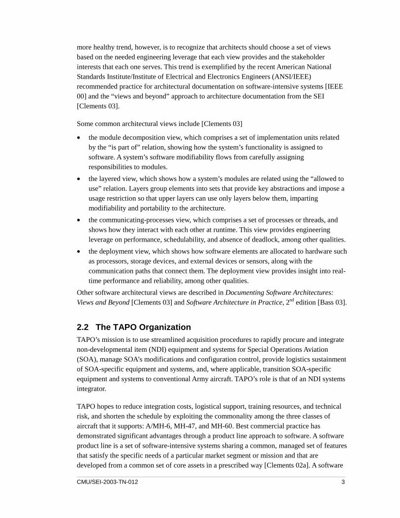
more healthy trend, however, is to recognize that architects should choose a set of views based on the needed engineering leverage that each view provides and the stakeholder interests that each one serves. This trend is exemplified by the recent American National Standards Institute/Institute of Electrical and Electronics Engineers (ANSI/IEEE) recommended practice for architectural documentation on software-intensive systems [IEEE 00] and the “views and beyond” approach to architecture documentation from the SEI [Clements 03].
Some common architectural views include [Clements 03]
• the module decomposition view, which comprises a set of implementation units related by the “is part of” relation, showing how the system’s functionality is assigned to software. A system’s software modifiability flows from carefully assigning responsibilities to modules.
• the layered view, which shows how a system’s modules are related using the “allowed to use” relation. Layers group elements into sets that provide key abstractions and impose a usage restriction so that upper layers can use only layers below them, imparting modifiability and portability to the architecture.
• the communicating-processes view, which comprises a set of processes or threads, and shows how they interact with each other at runtime. This view provides engineering leverage on performance, schedulability, and absence of deadlock, among other qualities.
• the deployment view, which shows how software elements are allocated to hardware such as processors, storage devices, and external devices or sensors, along with the communication paths that connect them. The deployment view provides insight into real-time performance and reliability, among other qualities.
Other software architectural views are described in Documenting Software Architectures: Views and Beyond [Clements 03] and Software Architecture in Practice, 2nd edition [Bass 03].
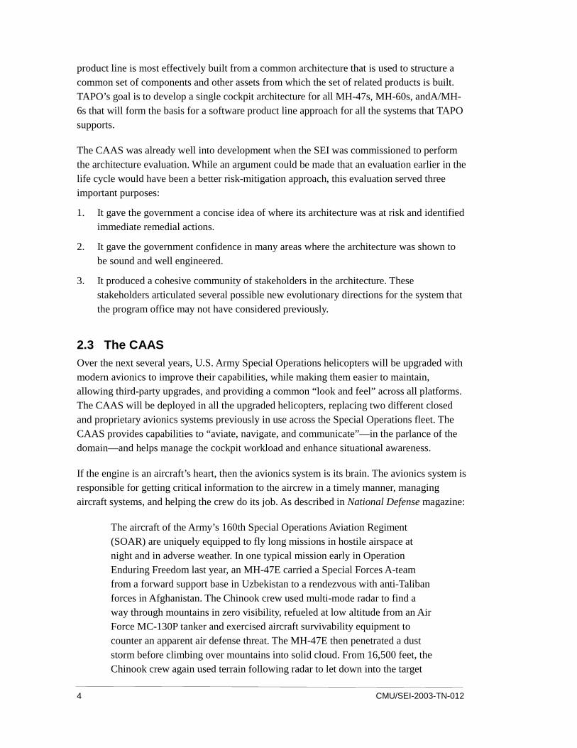
2.2 The TAPO Organization TAPO’s mission is to use streamlined acquisition procedures to rapidly procure and integrate non-developmental item (NDI) equipment and systems for Special Operations Aviation (SOA), manage SOA’s modifications and configuration control, provide logistics sustainment of SOA-specific equipment and systems, and, where applicable, transition SOA-specific equipment and systems to conventional Army aircraft. TAPO’s role is that of an NDI systems integrator.
TAPO hopes to reduce integration costs, logistical support, training resources, and technical risk, and shorten the schedule by exploiting the commonality among the three classes of aircraft that it supports: A/MH-6, MH-47, and MH-60. Best commercial practice has demonstrated significant advantages through a product line approach to software. A software product line is a set of software-intensive systems sharing a common, managed set of features that satisfy the specific needs of a particular market segment or mission and that are developed from a common set of core assets in a prescribed way [Clements 02a]. A software
4 CMU/SEI-2003-TN-012
product line is most effectively built from a common architecture that is used to structure a common set of components and other assets from which the set of related products is built. TAPO’s goal is to develop a single cockpit architecture for all MH-47s, MH-60s, andA/MH-6s that will form the basis for a software product line approach for all the systems that TAPO supports.
The CAAS was already well into development when the SEI was commissioned to perform the architecture evaluation. While an argument could be made that an evaluation earlier in the life cycle would have been a better risk-mitigation approach, this evaluation served three important purposes:
1. It gave the government a concise idea of where its architecture was at risk and identified immediate remedial actions.
2. It gave the government confidence in many areas where the architecture was shown to be sound and well engineered.
3. It produced a cohesive community of stakeholders in the architecture. These stakeholders articulated several possible new evolutionary directions for the system that the program office may not have considered previously.
2.3 The CAAS Over the next several years, U.S. Army Special Operations helicopters will be upgraded with modern avionics to improve their capabilities, while making them easier to maintain, allowing third-party upgrades, and providing a common “look and feel” across all platforms. The CAAS will be deployed in all the upgraded helicopters, replacing two different closed and proprietary avionics systems previously in use across the Special Operations fleet. The CAAS provides capabilities to “aviate, navigate, and communicate”—in the parlance of the domain—and helps manage the cockpit workload and enhance situational awareness.
If the engine is an aircraft’s heart, then the avionics system is its brain. The avionics system is responsible for getting critical information to the aircrew in a timely manner, managing aircraft systems, and helping the crew do its job. As described in National Defense magazine:
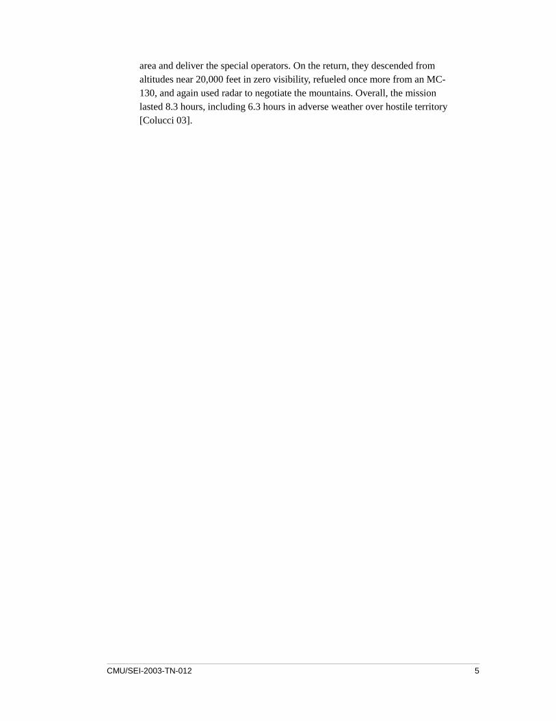
The aircraft of the Army’s 160th Special Operations Aviation Regiment (SOAR) are uniquely equipped to fly long missions in hostile airspace at night and in adverse weather. In one typical mission early in Operation Enduring Freedom last year, an MH-47E carried a Special Forces A-team from a forward support base in Uzbekistan to a rendezvous with anti-Taliban forces in Afghanistan. The Chinook crew used multi-mode radar to find a way through mountains in zero visibility, refueled at low altitude from an Air Force MC-130P tanker and exercised aircraft survivability equipment to counter an apparent air defense threat. The MH-47E then penetrated a dust storm before climbing over mountains into solid cloud. From 16,500 feet, the Chinook crew again used terrain following radar to let down into the target
CMU/SEI-2003-TN-012 5
area and deliver the special operators. On the return, they descended from altitudes near 20,000 feet in zero visibility, refueled once more from an MC-130, and again used radar to negotiate the mountains. Overall, the mission lasted 8.3 hours, including 6.3 hours in adverse weather over hostile territory [Colucci 03].

6 CMU/SEI-2003-TN-012
3 The ATAM
The ATAM relies on the principle that an architecture is suitable (or not suitable) only in the context of specific quality attributes that it must impart to the system. The ATAM uses stakeholders’ perspectives to produce a collection of scenarios that define the qualities of interest for the particular system under consideration. Scenarios give specific instances of usage, performance and growth requirements, various types of failures, and various possible threats and modifications. Once the important quality attributes are identified in detail, the architectural decisions relevant to each one can be illuminated and analyzed with respect to their appropriateness.
The steps of the ATAM leading up to analysis are carried out in two phases.1 In Phase 1, the evaluation team interacts with the system’s primary decision makers: the architect(s), manager(s), and perhaps a marketing or customer representative. During Phase 2, a larger group of stakeholders is assembled, including developers, testers, maintainers, administrators, and users. The two-phase approach ensures that the analysis is based on a broad and appropriate range of perspectives.
The steps of the ATAM are as follows.
Phase 1:
1. Present the ATAM. The evaluators explain the method so that those who will be involved in the evaluation understand it.
2. Present the business drivers. Appropriate system representative(s) present an overview of the system, its requirements, business goals, and context, and the architectural quality attribute drivers.
3. Present the architecture. The system or software architect (or another lead technical person) presents the architecture.
4. Catalog the architectural approaches. The system or software architect presents general architectural approaches to achieving specific qualities. The evaluation team captures a list and adds to it any approaches observed during Step 3 or learned during the pre-exercise review of the architecture documentation; for example, “A cyclic executive is used to ensure real-time performance.” Known architectural approaches have known quality attribute properties, and those approaches will help carry out the analysis steps.
1 These two phases, visible to the stakeholders, are bracketed by a preparation phrase up front and a
follow-up phase at the end; both are carried out behind the scenes.
CMU/SEI-2003-TN-012 7
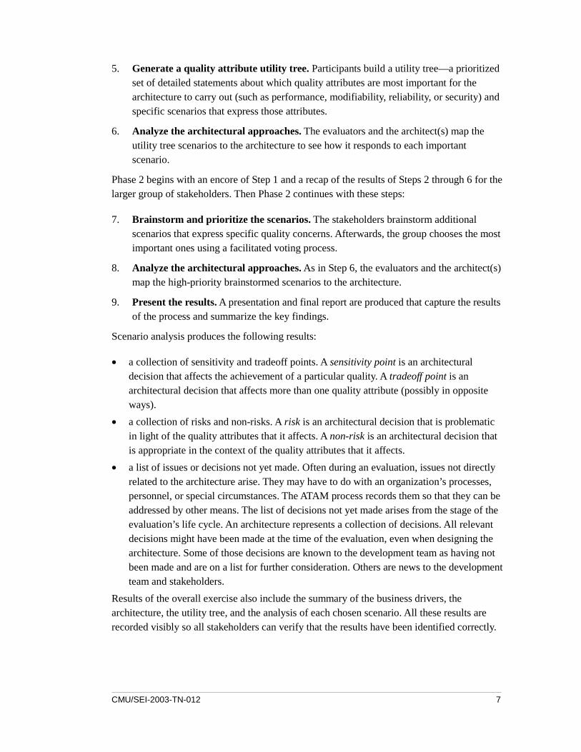
5. Generate a quality attribute utility tree. Participants build a utility tree—a prioritized set of detailed statements about which quality attributes are most important for the architecture to carry out (such as performance, modifiability, reliability, or security) and specific scenarios that express those attributes.
6. Analyze the architectural approaches. The evaluators and the architect(s) map the utility tree scenarios to the architecture to see how it responds to each important scenario.
Phase 2 begins with an encore of Step 1 and a recap of the results of Steps 2 through 6 for the larger group of stakeholders. Then Phase 2 continues with these steps:
7. Brainstorm and prioritize the scenarios. The stakeholders brainstorm additional scenarios that express specific quality concerns. Afterwards, the group chooses the most important ones using a facilitated voting process.
8. Analyze the architectural approaches. As in Step 6, the evaluators and the architect(s) map the high-priority brainstormed scenarios to the architecture.
9. Present the results. A presentation and final report are produced that capture the results of the process and summarize the key findings.
Scenario analysis produces the following results:
• a collection of sensitivity and tradeoff points. A sensitivity point is an architectural decision that affects the achievement of a particular quality. A tradeoff point is an architectural decision that affects more than one quality attribute (possibly in opposite ways).
• a collection of risks and non-risks. A risk is an architectural decision that is problematic in light of the quality attributes that it affects. A non-risk is an architectural decision that is appropriate in the context of the quality attributes that it affects.
• a list of issues or decisions not yet made. Often during an evaluation, issues not directly related to the architecture arise. They may have to do with an organization’s processes, personnel, or special circumstances. The ATAM process records them so that they can be addressed by other means. The list of decisions not yet made arises from the stage of the evaluation’s life cycle. An architecture represents a collection of decisions. All relevant decisions might have been made at the time of the evaluation, even when designing the architecture. Some of those decisions are known to the development team as having not been made and are on a list for further consideration. Others are news to the development team and stakeholders.
Results of the overall exercise also include the summary of the business drivers, the architecture, the utility tree, and the analysis of each chosen scenario. All these results are recorded visibly so all stakeholders can verify that the results have been identified correctly.
8 CMU/SEI-2003-TN-012
The number of scenarios that are analyzed during the evaluation is controlled by the amount of time allowed for the evaluation, but the process ensures (via active prioritization) that the most important ones are addressed.
After the evaluation, the evaluators write a report documenting the evaluation and recording the information discovered. This report will also document the framework for ongoing analysis that was discovered by the evaluators.
CMU/SEI-2003-TN-012 9
4 The Evaluation of the CAAS Software Architecture
4.1 Background Phase 1 of the evaluation took place at the Rockwell Collins facility in Cedar Rapids, Iowa on October 16, 2002. Twelve “decision maker” stakeholders were present, a number somewhat above average. They included five members of the contractor organization (architects and program managers), two members of the TAPO program office, and five members of the 160th Special Operations Aviation Regiment from Ft. Campbell, Kentucky, representing the user community. During Phase 1, six scenarios were analyzed.
Phase 2 took place at Fort Campbell on December 17 and 18, 2002. Fifteen stakeholders were present, representing various roles with a vested interest in the CAAS software architecture. Once again, the stakeholders came from the program office, the user community, and the contractor. Here, an additional 9 scenarios were analyzed, for a total of 15.
In both cases, the evaluation team consisted of four members of the technical staff from the SEI’s Product Line Systems Program.
4.2 Business and Mission Drivers Step 2 of the ATAM is a presentation of business drivers. A TAPO representative described the business objectives for the CAAS from the point of view of the government (in particular, the acquiring organization and the user organization), the driving business requirements for the CAAS products, and the architecture goals derived from those requirements.
Overall, the goal of the CAAS is to create a scalable system that meets the needs of multiple helicopter cockpits to address modernization issues. Its approach is to use a single, open, common avionics architecture system for all platforms to reduce the cost of ownership. This approach is based on Rockwell Collins’ Cockpit Management System (CMS) in its Flight 2 family of avionics systems, augmented with IAS2 functionality.
The four primary business drivers for the CAAS are
1. Minimize systems acquisition and sustainment costs.
2. Reduce the total ownership cost over the life of the avionics system.
3. Modernize the system with minimal impact to Army Special Operations readiness.
4. Ensure that new CAASs work well with other programs.
Strategies to achieve these drivers include
2 IAS is a legacy avionics system developed by another contractor.
10 CMU/SEI-2003-TN-012
• Leverage existing code and documentation where practical.
• Aim for a “plug and play” architecture in which hardware is portable between platforms.
• Move away from single proprietary components and use standards where appropriate.
• Provide cross-platform commonality (hardware, software, and training).
• Reduce the logistics base.
• Use the Service Life Extension Program (SLEP) as a fleet modification/installation center as much as possible.
• Leverage other platform developments (both commercial and DoD).
• Employ a system infrastructure or framework that facilitates system maintenance and enhancements (including third-party participation in them).
Additional business drivers that play a role are the constraints on the system and its architecture, which, in the CAAS, include a large set of applicable standards.
The business drivers are elicited to establish the broad requirements and context for the system, but also to identify the driving quality attribute requirements for the architecture. For the CAAS, the important quality attributes (in order of customer importance) are
• availability
• performance (i.e., provide timely answers)
• modifiability
Modifiability, as is often the case, manifests itself in a number of ways. For the CAAS, modifiability refers to the following capabilities:
• growth
• testability
• openness
• portability of hardware and software across different aircraft platforms
• reconfigurability
• repeatability (That is, every system must look like every other system and provide the same answer on every platform.)
• supportability (i.e., the ability of a third party to maintain the system)
• reuse
• affordability
These quality attributes serve as the first approximation qualities of importance in the generation of the quality attribute utility tree, detailed in Section 4.4.
CMU/SEI-2003-TN-012 11
4.3 Architectural Approaches Step 4 of the ATAM captures the list of architectural approaches gleaned from the architecture presentation, as well as from the evaluation team’s pre-exercise review of the architecture documentation. Because architectural approaches exhibit known effects on quality attributes (e.g., redundancy increases availability, whereas layering increases portability), explicitly identifying the approaches provides input for the analysis steps that follow.
The overarching strategies used in the CAAS are strongly partitioning applications and structuring the software as a series of layers. POSIX provides the primary partitioning mechanism that establishes inviolable timing and memory walls between applications to prevent conflicts. For example, an important result of this design is that an application that for some reason overruns its processing time limit cannot cause another application to be late. Similarly, an application that overruns its memory allotment cannot impinge on another application’s memory area.
Applications hence represent encapsulations. One of the strongest aspects of the CAAS architecture is that its design allows applications to be changed more or less independently of each other. That aspect, along with location transparency (an application’s independence from its hardware location), makes adding new applications a straightforward process.
The CAAS software architectural approaches are listed below along with the quality attributes that each one nominally affects. The attributes are shown in parentheses.
1. consistent partitioning strategy: definition of a partition, “brick-wall partitioning” (availability, safety, modifiability, testability, maintainability)
2. encapsulation: used to isolate partitions. Between partitions, applications can share only their state via the network. The remote service interface (RSI) and remote service provider (RSP) are examples of encapsulation that isolate the network implementation details. (modifiability, availability)
3. interface strategy: Accessing components only via their interfaces is strictly followed. Besides controlling interactions and eliminating the back-door exploitation of changeable implementation details, this strategy reduces the number of inputs and outputs per partition. (modifiability, maintainability)
4. layers: used to partition and isolate high-level graphics services (portability, modifiability)
5. distributed processing: Predominantly, a client-server approach is used to decouple “parts” of the system. Also, the Broadcast feature is used to broadcast information periodically. (maintainability, modifiability)
12 CMU/SEI-2003-TN-012
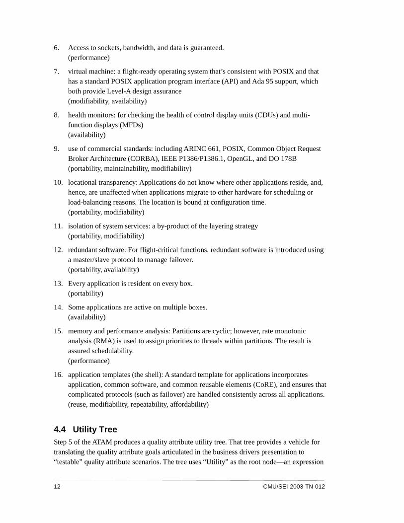
6. Access to sockets, bandwidth, and data is guaranteed. (performance)
7. virtual machine: a flight-ready operating system that’s consistent with POSIX and that has a standard POSIX application program interface (API) and Ada 95 support, which both provide Level-A design assurance (modifiability, availability)
8. health monitors: for checking the health of control display units (CDUs) and multi-function displays (MFDs) (availability)
9. use of commercial standards: including ARINC 661, POSIX, Common Object Request Broker Architecture (CORBA), IEEE P1386/P1386.1, OpenGL, and DO 178B (portability, maintainability, modifiability)
10. locational transparency: Applications do not know where other applications reside, and, hence, are unaffected when applications migrate to other hardware for scheduling or load-balancing reasons. The location is bound at configuration time. (portability, modifiability)
11. isolation of system services: a by-product of the layering strategy (portability, modifiability)
12. redundant software: For flight-critical functions, redundant software is introduced using a master/slave protocol to manage failover. (portability, availability)
13. Every application is resident on every box. (portability)
14. Some applications are active on multiple boxes. (availability)
15. memory and performance analysis: Partitions are cyclic; however, rate monotonic analysis (RMA) is used to assign priorities to threads within partitions. The result is assured schedulability. (performance)
16. application templates (the shell): A standard template for applications incorporates application, common software, and common reusable elements (CoRE), and ensures that complicated protocols (such as failover) are handled consistently across all applications. (reuse, modifiability, repeatability, affordability)
4.4 Utility Tree Step 5 of the ATAM produces a quality attribute utility tree. That tree provides a vehicle for translating the quality attribute goals articulated in the business drivers presentation to “testable” quality attribute scenarios. The tree uses “Utility” as the root node—an expression
CMU/SEI-2003-TN-012 13
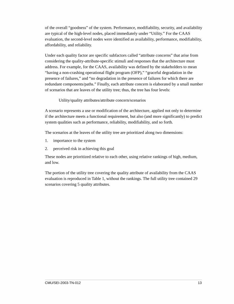
of the overall “goodness” of the system. Performance, modifiability, security, and availability are typical of the high-level nodes, placed immediately under “Utility.” For the CAAS evaluation, the second-level nodes were identified as availability, performance, modifiability, affordability, and reliability.
Under each quality factor are specific subfactors called “attribute concerns” that arise from considering the quality-attribute-specific stimuli and responses that the architecture must address. For example, for the CAAS, availability was defined by the stakeholders to mean “having a non-crashing operational flight program (OFP),” “graceful degradation in the presence of failures,” and “no degradation in the presence of failures for which there are redundant components/paths.” Finally, each attribute concern is elaborated by a small number of scenarios that are leaves of the utility tree; thus, the tree has four levels:
Utility/quality attributes/attribute concern/scenarios
A scenario represents a use or modification of the architecture, applied not only to determine if the architecture meets a functional requirement, but also (and more significantly) to predict system qualities such as performance, reliability, modifiability, and so forth.
The scenarios at the leaves of the utility tree are prioritized along two dimensions:
1. importance to the system
2. perceived risk in achieving this goal
These nodes are prioritized relative to each other, using relative rankings of high, medium, and low.
The portion of the utility tree covering the quality attribute of availability from the CAAS evaluation is reproduced in Table 1, without the rankings. The full utility tree contained 29 scenarios covering 5 quality attributes.

14 CMU/SEI-2003-TN-012
Table 1: Utility Tree for the Availability Quality Attribute
Phase 1: Quality Attribute Utility Tree Quality Attribute
availability
Attribute Concerns
The OFP doesn’t crash.
1. Invalid data is entered by the pilot, and the system does not crash. 2. Invalid data comes from an actor on any bus, and the system does not
crash.
Scenarios
3. When a 1.9-second power interruption occurs, the system will execute a warm boot and be fully operational in 2 seconds.
Attribute Concerns
graceful degradation in the presence of failures
1. A loss of Doppler occurs, the pilot is notified, and the Doppler timer begins a countdown (for multi-mode radar [MMR] validity).
Scenarios
2. A partition fails, the rest of the processor continues working, and the system continues to function.
Attribute Concerns
no degradation in the presence of failures for which there are redundant components/paths 1. The data concentrator suffers battle damage, and all flight-critical
information is still available. Scenarios
2. The mission processor in the outboard MFD fails, and that display and the rest of the system continue to operate normally.
For the CAAS evaluation, the evaluation team chose six of the highest priority scenarios and analyzed them during Phase 1. The scenarios that were not analyzed were distributed to Phase 2 participants as “seed scenarios” that they could place into the brainstorming pool, if desired.
4.5 Scenario Generation and Prioritization In addition to the scenarios at the leaves of the utility tree, a scenario elicitation process in Step 7 allows stakeholders to contribute additional scenarios that reflect their concerns and understanding of how the architecture will accommodate their needs. A particular scenario may, in fact, have implications for many stakeholders. For a modification, one stakeholder may be concerned with the difficulty of a change and its performance impact, while another may be interested in how the change will affect the integrability of the architecture.
After the scenarios were generated, the stakeholders were given the opportunity to merge those that seemed to address closely related concerns. The purpose of scenario consolidation is to prevent votes from being split across two almost-alike scenarios.
After merging, the scenarios were prioritized using a voting process in which participants were given six votes3 that they could allocate to any scenario or group of scenarios.
A few of the 21 scenarios brainstormed during Step 7 are shown in Table 2.
3 The number of votes is 30% of the number of brainstormed scenarios, rounded up to the nearest
integer. This is a common facilitated brainstorming and group-consensus technique.

CMU/SEI-2003-TN-012 15
Table 2: Brainstormed Scenarios from Step 7
Phase 2: Brainstormed Scenarios Scenario Number
Scenario Text Number of Votes
2 Changes to the CAAS are reflected in the simulation and training system concurrently with the airframe changes, without coding it twice (simulation and training stakeholder).
5
3 No single point of failure in the system will affect the system’s safety or performance (system architect stakeholder).
10
5 Multiple versions of the system must be fielded at the same time. Those versions should be distinguishable and should not have a negative impact on the rest of the system (system implementer stakeholder).
1
9 75% of the CAAS is built from reused components increasing new business opportunities (from Phase 1, program manager stakeholder).
9
13 Given maximum “knob twiddling” to the level that the system’s performance is degraded, the system can prioritize its flight-critical functions, so they are NOT degraded (safety stakeholder).
6
15 Given the need for a second ARC231, the radio can be incorporated into the existing system by reusing existing software at minimal or no cost (requirements stakeholder).
2
20 An application doesn’t crash, but starts producing bad data. The system can detect the errant data and when applications crash (reliability stakeholder).
3
Step 7 concludes with an examination of how the newly introduced high-priority scenarios compare with the high-priority scenarios identified in the utility tree. A low degree of overlap (in terms of the specific, detailed quality attributes addressed by the scenarios) could indicate that the project’s decision makers and stakeholders had different expectations. That would constitute a risk to the project.
4.6 Overview of the Analysis Process A total of 15 scenarios were analyzed during the course of the CAAS evaluation: 6 from the Phase 1 utility tree and 9 from the Phase 2 scenario generation/prioritization process.
The evaluation team concluded that the CAAS architecture seemed sound with respect to most of the behavioral and quality attribute requirements levied on it. The architecture was found to be well partitioned, and although the size of some of the partitions was a concern with respect to their modifiability, overall, the partitioning scheme provided a robust foundation for evolutionary flexibility. The evaluation found that the architecture was robust with respect to the addition of new functionality and hardware.
The evaluation identified 18 risks related to the software architecture’s ability to satisfy its behavioral, quality attribute, and evolutionary goals. In addition, 12 non-risks (areas of
16 CMU/SEI-2003-TN-012
design strength) were identified.4 An example risk was “OFP has no built-in hooks to aid in simulation/training capability,” referring to the goal of making the same operational software drive both the simulators and the actual helicopters. An example non-risk was “the number of sockets used by the system is known and guaranteed,” allowing reliable performance estimation to be carried out.
Five sensitivity points (e.g., “isolating operating system dependencies enhances portability”) and two tradeoff points (e.g., “letting users set I/O parameters [such as turbine gas temperature limits] increases flexibility and usability, while decreasing safety”) were cataloged.
In addition to the items described above, the evaluation team collected a series of issues—areas of programmatic concern not directly related to the technical aspects of the software architecture. For example, one issue involved the stakeholders’ expressed need for a new functional capability that was out of the scope of the current requirements and that would be hard to provide. These issues were then brought to the attention of the program office, where they were handled appropriately.
The identified risks suggest a set of four “themes” in the architecture. These themes represent the key architectural issues posing potential problems for future success and possibly threatening the business drivers identified during Step 2. For example, several of the analyzed scenarios dealt with performance, and revealed risks about unknown performance requirements and certain performance goals not being met. These scenarios suggested a risk theme: More attention should be focused on performance. Such concise syntheses allowed the program office to focus on a few key areas that would improve its chances for success in both current development and future evolution.
4.7 Post-ATAM Activities Although the details of post-ATAM activities are still being worked out with the program office, there are several possibilities. For example, the evaluation uncovered places where the software architecture documentation could be improved, and the SEI can help TAPO to do that.
4 The ATAM process concentrates on identifying risks rather than non-risks, and so oftentimes, more
risks are uncovered than non-risks. The relative numbers are not indicative of the architecture’s quality.
CMU/SEI-2003-TN-012 17
5 Conclusions
5.1 Benefits Every ATAM exercise is followed by a survey of stakeholders in attendance. The survey asks, “Do you feel you will be able to act on the results of the architecture evaluation? What follow-on actions do you anticipate? How much time do you anticipate spending on them?” Here is what those responding had to say verbatim:
• “Yes, greater review of latency”
• “Yes, I would expect the government to consider program changes to make improvements to the system. There will be detailed review and action plans delivered for risk items.”
• “Difficult to ascertain since this review was conducted during code and test phase of program. We will act on those items that affect future business/enhancements in conjunction with our customer.”
• “Minimal actions by a user are available.”
• “Because we are so far down the road with the CAAS, we don’t see any major changes, but we are better aware of risk areas.”
• “I expect to spend at least hours in meetings/dialogue about the [risks and issues found].”
• “Immediate impact is limited due to the point we are at in the program. Little will be done now. May have impact as the system is evolved.”
The survey asks the participants if they feel the exercise was useful. Here is what they said:
• “Yes, [it] caused a critical look at the CAAS. It validated some architectural decisions and raised questions about others.”
• “In general, evaluation process seems worthwhile.
• “As a maintainer/trainer, it helped me to understand the system.”
• “Unknown at this point”
• “Yes, very useful”
• “Yes, it brought issues and concerns to our attention.”
Several stakeholders lamented that the evaluation was not performed earlier. Since the project was already in the development phase, the evaluation may have had a lesser impact than it would have otherwise:
• “Would have been more useful earlier on in the design/requirements definition phase”
• “[It was useful], but done too late to be of significant impact.”

18 CMU/SEI-2003-TN-012
• “Do earlier! This type of exercise would have been more useful 12-14 months ago when the design decisions were being made. If ATAM was accomplished then, more issues/risks could have been addressed.”
• “The whole process would have been more useful if it had taken place one to two years ago.”
5.2 Summary Overall, this evaluation succeeded in
• raising awareness of the importance of stakeholders in the architecture process
• establishing a community of vested stakeholders and opening channels of communication among them
• identifying a number of risk themes that can be made the subject of intense mitigation efforts that, even though the system is in development, can be effective in heading off disaster
• raising a number of issues with respect to previously unplanned capabilities for which some stakeholders expressed an acute need
• elevating the role of software architecture in system acquisition
It demonstrates the applicability and usefulness of software architecture evaluation in a DoD acquisition context. The evaluation comments underscore the SEI’s advice that software architecture evaluations be performed before code is developed so that surfaced risks can be mitigated when it is least costly to do so. There never seems to be time in a development schedule to insert an architecture evaluation, but other ATAM evaluations have proven that the time spent saves considerable time and cost later [Clements 02b].
CMU/SEI-2003-TN-012 19
References
[Bass 03] Bass, L.; Clements, P.; & Kazman, R. Software Architecture in Practice, 2nd edition. Boston, MA: Addison-Wesley, 2003.
[Clements 02a] Clements, P. & Northrop, L. Software Product Lines: Practices and Patterns. Boston, MA: Addison-Wesley, 2002.
[Clements 02b] Clements, P.; Kazman, R.; & Klein, M. Evaluating Software Architectures: Methods and Case Studies. Boston, MA: Addison-Wesley, 2002.
[Clements 03] Clements, P.; Bachmann, F.; Bass, L.; Garlan, D.; Ivers, J.; Little, R.; Nord, R.; & Stafford, J. Documenting Software Architectures: Views and Beyond. Boston, MA: Addison-Wesley, 2003.
[Colucci 03] Colucci, F. “Avionics Upgrade Underway for Special Ops Helicopters.” National Defense 87, 591 (February 2003): 24-26. <http://www.nationaldefensemagazine.org/article.cfm?Id=1029>.
[IEEE 00] IEEE Computer Society, Software Engineering Standards Committee, Institute of Electrical and Electronics Engineers, IEEE-SA Standards Board, and IEEE Xplore. IEEE Recommended Practice for Architectural Description of Software-Intensive Systems. New York, NY: Institute of Electrical and Electronic Engineers, 2000.
[Kazman 00] Kazman, R.; Klein, M.; & Clements, P. ATAM: Method for Architecture Evaluation (CMU/SEI-2000-TR-004, ADA382629). Pittsburgh, PA: Software Engineering Institute, Carnegie Mellon University, 2000. <http://www.sei.cmu.edu/publications/documents/00.reports /00tr004.html>.

20 CMU/SEI-2003-TN-012
REPORT DOCUMENTATION PAGE Form Approved OMB No. 0704-0188
Public reporting burden for this collection of information is estimated to average 1 hour per response, including the time for reviewing instructions, searching existing data sources, gathering and maintaining the data needed, and completing and reviewing the collection of information. Send comments regarding this burden estimate or any other aspect of this collection of information, including suggestions for reducing this burden, to Washington Headquarters Services, Directorate for information Operations and Reports, 1215 Jefferson Davis Highway, Suite 1204, Arlington, VA 22202-4302, and to the Office of Management and Budget, Paperwork Reduction Project (0704-0188), Washington, DC 20503.
1. AGENCY USE ONLY
(Leave Blank)
2. REPORT DATE
July 2003
3. REPORT TYPE AND DATES COVERED
Final 4. TITLE AND SUBTITLE
Using the Architecture Tradeoff Analysis MethodSM (ATAMSM) to Evaluate the Software Architecture for a Product Line of Avionics Systems: A Case Study
5. FUNDING NUMBERS
F19628-00-C-0003
6. AUTHOR(S)
Mario Barbacci, Paul Clements, Anthony Lattanze, Linda Northrop, William Wood 7. PERFORMING ORGANIZATION NAME(S) AND ADDRESS(ES)
Software Engineering Institute Carnegie Mellon University Pittsburgh, PA 15213
8. PERFORMING ORGANIZATION REPORT NUMBER
CMU/SEI-2003-TN-012
9. SPONSORING/MONITORING AGENCY NAME(S) AND ADDRESS(ES)
HQ ESC/XPK 5 Eglin Street Hanscom AFB, MA 01731-2116
10. SPONSORING/MONITORING AGENCY REPORT NUMBER
11. SUPPLEMENTARY NOTES
12A DISTRIBUTION/AVAILABILITY STATEMENT
Unclassified/Unlimited, DTIC, NTIS
12B DISTRIBUTION CODE
13. ABSTRACT (MAXIMUM 200 WORDS)
The quality of a software-intensive system depends heavily on the system’s software architecture. When used appropriately, software architecture evaluations can have a favorable effect on a delivered or modified government system. This technical note describes the application of the Architecture Tradeoff Analysis MethodSM (ATAMSM) to an Army avionics system acquisition. A government–contractor team is developing the Common Avionics Architecture System (CAAS) for a family of U.S. Army Special Operations helicopters. This technical note presents the contextual background about the software architecture, the organization, and the system being evaluated. It also provides a general overview of the ATAM process, describes the application of the ATAM to the CAAS, and presents important results and benefits.
14. SUBJECT TERMS
TAPO, ATAM, Architecture Tradeoff Analysis Method, acquisition organizations, experience report
15. NUMBER OF PAGES
30
16. PRICE CODE
17. SECURITY CLASSIFICATION
OF REPORT
Unclassified
18. SECURITY CLASSIFICATION OF THIS PAGE
Unclassified
19. SECURITY CLASSIFICATION OF ABSTRACT
Unclassified
20. LIMITATION OF ABSTRACT
UL
NSN 7540-01-280-5500 Standard Form 298 (Rev. 2-89) Prescribed by ANSI Std. Z39-18 298-102