Using Task Analytic Behavior Modeling, Erroneous Human...
271
Using Task Analytic Behavior Modeling, Erroneous Human Behavior Generation, and Formal Methods to Evaluate the Role of Human-automation Interaction in System Failure A Dissertation Presented to the faculty of the School of Engineering and Applied Science University of Virginia In Partial Fulfillment of the requirements for the Degree Doctor of Philosophy Systems Engineering by Matthew L. Bolton August 2010
Transcript of Using Task Analytic Behavior Modeling, Erroneous Human...
Using Task Analytic Behavior Modeling, ErroneousHuman Behavior Generation, and Formal Methods toEvaluate the Role of Human-automation Interaction in
System Failure
A Dissertation
Presented to
the faculty of the School of Engineering and Applied Science
University of Virginia
In Partial Fulfillment
of the requirements for the Degree
Doctor of Philosophy
Systems Engineering
by
Matthew L. Bolton
August 2010

c© Copyright August 2011
Matthew L. Bolton
All rights reserved
Approvals
This dissertation is submitted in partial fulfillment of the requirements for the degree of
Doctor of Philosophy
Systems Engineering
Matthew L. Bolton
Approved:
Ellen J. Bass (Advisor)
Gregory J. Gerling
Margaret L. Plews-Ogan
Stephen D. Patek (Chair)
Westley Weimer
Accepted by the School of Engineering and Applied Science:
James H. Aylor (Dean)
August 2010

Abstract
Failures in complex, safety-critical systems often arise as a result of interactions between
the elements of the system, including its human operator. Two sub-disciplines, human-
automation interaction (from human factors engineering) and formal methods (from com-
puter science) have attempted to address these types of problems from two different di-
rections. Human-automation interaction researchers use tools such as task analysis and
models of erroneous human behavior to investigate the way human operators interact with
automation in order to design systems that facilitate safe, human work. Formal methods
researchers use well defined mathematical modeling and proof techniques to verify that
system models (often with concurrent interacting processes) do or do not exhibit desired
properties. Model checking is a particular type of formal verification which proves that
a system does or does not exhibit a specified property by searching for a violation in a
system’s entire statespace. It returns a counterexample (execution trace) illustrating any
violation it discovers.
This work shows that it is possible to automatically predict the contribution of both
normative and automatically generated erroneous human behavior to failures in human-
automation interactive systems using formal verification. We have developed a computa-
tional method which utilizes task analytic models, formal system modeling, model check-
ing, and taxonomies of erroneous human behavior to automatically incorporate erroneous
human behavior patterns into normative task models, allowing analysts to formally verify
iv
v
system safety properties with both normative and erroneous human behavior. As part of
this research, we developed a novel human task behavior modeling language (called the
Enhanced Operator Function Model (EOFM)) with a defined formal semantics and a vi-
sual notation for graphical display. This allows normative human behavior to be modeled
as a hierarchy of activities and actions, where actions can be sequenced using a superset of
the temporal relationships supported by similar modeling paradigms. We have also devel-
oped two erroneous human behavior generation methods which allow instantiated EOFMs
to be systematically manipulated in order to encompass erroneous human behavior consis-
tent with Hollangel’s phenotypes of erroneous human behavior and Reason’s attentional
slips. In order to allow instantiated EOFMs (either normative or erroneous) to be formally
verifiable, we have developed a translator which converts instantiated EOFMs into the for-
mal modeling language of the Symbolic Analysis Laboratory, thus allowing task behavior
models to be formally verified. We have also developed an architectural framework for
formally modeling human-automation interactive systems which coordinates the behavior
of formal models of (translated) human task behavior, human mission goals, device au-
tomation, the human-device interface, and the operation environment. Finally, we have
developed a novel visualization which uses the architectural framework and the EOFM’s
visual notation to convey the information contained in a model checker counterexample.
We describe the motivation and design for each element of our method. We provide
validation testing results which confirm that our method is behaving as we intended. We
present benchmarks that show how our method scales. We also demonstrate the different
ways in which our method can be used to evaluate human-automation interactive systems
with several realistic applications: a patient controlled analgesia pump, an automobile with
a cruise control, a radiation therapy machine, and an aircraft on approach. These appli-
cations are used to show how the method can be adapted to verify systems that require
different elements of our architectural framework. They are also used to demonstrate how

vi
different instantiations of architectural elements can be incorporated into application sys-
tem models to facilitate different analyses, the evaluation of different designs, and the
exploration of design interventions for correcting problems discovered using our method.

Acknowledgments
The work described was supported in part by Grant Number T15LM009462 from the Na-
tional Library of Medicine (NLM) and Research Grant Agreement UVA-03-01, sub-award
6073-VA and 2723-VA from the National Institute of Aerospace (NIA). The content is
solely the responsibility of the author and does not necessarily represent the official views
of the NIA, National Aeronautics and Space Administration, NLM, or National Institutes
of Health.
The author would like to thank his adviser Ellen J. Bass for her help and guidance on
this work. He would like to thank his collaborators Radu Siminiceanu, Michael Feary, and
Ben Di Vito for their insights into the background materials and technical aspects of this
work. He would like to thank his PhD committee members Gregory J. Gerling, Stephen D.
Patek, Margaret Plews-Ogan, and Westley Weimer for their help and support through the
PhD process. He would like to thank Diane Haddon, John Knapp, Paul Merrel, Kathryn
McGough, and Sherry Wood of the University of Virginia Health System for helping him
understand the functionality of the Baxter Ipump and for providing the necessary docu-
mentation, training materials, and device access.
The author would like to thank Thomas Hutchinson for his mentorship early in the
author’s academic career and getting him started in human factors engineering.
vii
Contents
1 Human-automation Interaction and Formal Verification 1
1.1 Formal Verification of Human-device Interfaces . . . . . . . . . . . . . . 6
1.2 Formal Verification and Mode Confusion . . . . . . . . . . . . . . . . . 10
1.3 Formal Verification and Task Analytic Models . . . . . . . . . . . . . . . 12
1.4 Formal Verification and Cognitive Models . . . . . . . . . . . . . . . . . 15
1.5 Limitations of Current Techniques and Technologies . . . . . . . . . . . 17
1.6 Research Objectives: A Method to Evaluate the Role of Human-
automation Interaction in System Failure . . . . . . . . . . . . . . . . . . 21
2 The Enhanced Operator Function Model: Syntax and Formal Semantics 29
2.1 Enhanced Operator Function Model . . . . . . . . . . . . . . . . . . . . 30
2.2 Language Description . . . . . . . . . . . . . . . . . . . . . . . . . . . . 31
2.3 Discussion . . . . . . . . . . . . . . . . . . . . . . . . . . . . . . . . . . 40
3 Formal Modeling Architectural Framework 46
3.1 Methods . . . . . . . . . . . . . . . . . . . . . . . . . . . . . . . . . . . 49
3.2 Phase 1a: A Representative Model of the Ipump . . . . . . . . . . . . . . 53
3.3 Phase 1b: A Reduced Baxter Ipump Model . . . . . . . . . . . . . . . . 55
3.4 Phase 1c: A Simpler PCA Pump Model . . . . . . . . . . . . . . . . . . 59
3.5 Phase 2: Incorporating Models of Human Behavior . . . . . . . . . . . . 61
viii

Contents ix
3.6 Discussion . . . . . . . . . . . . . . . . . . . . . . . . . . . . . . . . . . 67
4 EOFM to SAL Translator 73
4.1 EOFM to SAL Translation . . . . . . . . . . . . . . . . . . . . . . . . . 74
4.2 Validation and Benchmarking . . . . . . . . . . . . . . . . . . . . . . . . 77
4.3 Application: Cruise Control System . . . . . . . . . . . . . . . . . . . . 79
4.4 Discussion . . . . . . . . . . . . . . . . . . . . . . . . . . . . . . . . . . 95
5 Phenotypical Erroneous Human Behavior Generation 97
5.1 Erroneous Human Behavior Taxonomies . . . . . . . . . . . . . . . . . . 98
5.2 Automatic Phenotypical Erroneous Human Behavior Generation . . . . . 99
5.3 Testing and Benchmarks . . . . . . . . . . . . . . . . . . . . . . . . . . 101
5.4 Application . . . . . . . . . . . . . . . . . . . . . . . . . . . . . . . . . 103
5.5 Discussion . . . . . . . . . . . . . . . . . . . . . . . . . . . . . . . . . . 110
6 Strategic Knowledge-based Erroneous Behavior Generation 115
6.1 Automatic Strategic Knowledge-based Erroneous Human Behavior Gen-
eration . . . . . . . . . . . . . . . . . . . . . . . . . . . . . . . . . . . . 117
6.2 Testing and Benchmarks . . . . . . . . . . . . . . . . . . . . . . . . . . 119
6.3 Application . . . . . . . . . . . . . . . . . . . . . . . . . . . . . . . . . 121
6.4 Discussion . . . . . . . . . . . . . . . . . . . . . . . . . . . . . . . . . . 125
7 Counterexample Visualization 130
7.1 Counterexample Visualization Techniques . . . . . . . . . . . . . . . . . 130
7.2 Operational Concept and Design . . . . . . . . . . . . . . . . . . . . . . 133
7.3 Example 1: Evaluating a System with a Normative Task Model . . . . . . 136
7.4 Example 2: Evaluating a System with a Phenotypical Erroneous Task Model140
Contents x
7.5 Example 3: Evaluating a System with a Knowledge-based Erroneous Task
Model . . . . . . . . . . . . . . . . . . . . . . . . . . . . . . . . . . . . 141
7.6 Discussion . . . . . . . . . . . . . . . . . . . . . . . . . . . . . . . . . . 144
8 Design Exploration 147
8.1 Application: Aircraft on Approach . . . . . . . . . . . . . . . . . . . . . 147
8.2 Formal System Model . . . . . . . . . . . . . . . . . . . . . . . . . . . . 151
8.3 Human Task Behavior Modeling . . . . . . . . . . . . . . . . . . . . . . 157
8.4 EOFM to SAL Translation . . . . . . . . . . . . . . . . . . . . . . . . . 159
8.5 Specification . . . . . . . . . . . . . . . . . . . . . . . . . . . . . . . . 159
8.6 Apparatus . . . . . . . . . . . . . . . . . . . . . . . . . . . . . . . . . . 161
8.7 Phase 1 Analyses: Exploring Different Representations of Normative Hu-
man Behavior . . . . . . . . . . . . . . . . . . . . . . . . . . . . . . . . 161
8.8 Phase 2 Analyses: Exploring Different Representations of Erroneous Hu-
man Behavior . . . . . . . . . . . . . . . . . . . . . . . . . . . . . . . . 165
8.9 Phase 3 Analyses: Exploring Variations in the Behavior of the Automation 180
8.10 General Discussion . . . . . . . . . . . . . . . . . . . . . . . . . . . . . 186
9 Contributions and Future Work 187
9.1 Future Development of the Method . . . . . . . . . . . . . . . . . . . . . 192
9.2 Future Development of Formal Verification of Human-automation Interaction195
9.3 Conclusion . . . . . . . . . . . . . . . . . . . . . . . . . . . . . . . . . 200
A EOFM Code Listing for the Driver Task Behavior Model 201
B EOFM to SAL Translator Validation 204
B.1 Activity Execution State Transition Specification Patterns . . . . . . . . . 204
B.2 Action Execution State Transition Specification Patterns . . . . . . . . . 206
Contents xi
B.3 Restrictions on Activity and Action Execution Parallelism . . . . . . . . 207
B.4 Validation Applications . . . . . . . . . . . . . . . . . . . . . . . . . . . 208
B.5 A Single Top Level Activity Decomposing Into Activities . . . . . . . . . 213
B.6 Results . . . . . . . . . . . . . . . . . . . . . . . . . . . . . . . . . . . . 218
B.7 Conclusions . . . . . . . . . . . . . . . . . . . . . . . . . . . . . . . . . 218
C Phenotypical Erroneous Human Behavior Validation 219
D Strategic Knowledge-based Erroneous Behavior Validation 223
Bibliography 228
List of Figures
1.1 Method for predicting how both normative and erroneous human behavior
may contribute to system failure using model checking. . . . . . . . . . . 24
2.1 The EOFM Relax NG Language Specification . . . . . . . . . . . . . . . 33
2.2 An example EOFM for programming the buzzer time into a digital alarm
clock. . . . . . . . . . . . . . . . . . . . . . . . . . . . . . . . . . . . . 37
2.3 (a) Execution state transition diagram for a generic activity. (b) Execution
state transition diagram for a generic action. . . . . . . . . . . . . . . . . 41
3.1 Framework for the formal modeling of human-automation interaction. . . 47
3.2 A simplified representation of the Baxter Ipump’s human-device interface. 50
3.3 The EOFM graphical representation for turning on the pump. . . . . . . . 62
3.4 The EOFM graphical representation for stopping infusion. . . . . . . . . 63
3.5 The EOFM graphical representation for turning off the pump. . . . . . . . 64
3.6 The EOFM graphical representation of the pattern for programming a value
X into the pump. . . . . . . . . . . . . . . . . . . . . . . . . . . . . . . 65
3.7 The EOFM for choosing to start or review a prescription. . . . . . . . . . 66
4.1 Cruise control model scenario. . . . . . . . . . . . . . . . . . . . . . . . 79
4.2 State transition diagram depicting the formal model’s behavior for the gas
pedal (Pedal). . . . . . . . . . . . . . . . . . . . . . . . . . . . . . . . . 81
xii
List of Figures xiii
4.3 State transition diagram depicting the formal model’s behavior for the state
of the cruise control (Cruise). . . . . . . . . . . . . . . . . . . . . . . . . 82
4.4 State transition diagram depicting the formal model’s behavior for the state
of the cruise speed (CruiseSpeed). . . . . . . . . . . . . . . . . . . . . . 83
4.5 State transition diagram depicting the formal model’s behavior for the state
of the car’s speed (CarSpeed). . . . . . . . . . . . . . . . . . . . . . . . 84
4.6 State transition diagram depicting the formal model’s behavior for the state
of the car’s acceleration (CarAcceleration). . . . . . . . . . . . . . . . . 85
4.7 State transition diagram depicting the formal model’s behavior for the traf-
fic light (TrafficLight). . . . . . . . . . . . . . . . . . . . . . . . . . . . 86
4.8 State transition diagram depicting the formal model’s behavior for the pres-
ence of merging traffic (Traffic). . . . . . . . . . . . . . . . . . . . . . . 86
4.9 State transition diagram depicting the formal model’s behavior for the rel-
ative distance/interval of the car to the traffic light (TrafficLightDistance). 87
4.10 Visualization of the EOFM task model for driving at the desired speed. . . 88
4.11 Visualization of the EOFM for avoiding to merging traffic. . . . . . . . . 90
4.12 Visualization of the EOFM for responding to a traffic light. . . . . . . . . 91
5.1 Visualization of the EOFM structure used to generate a zero-order pheno-
typical erroneous human behavior. . . . . . . . . . . . . . . . . . . . . . 100
5.2 Plot of the maximum number of erroneous acts vs. the number of states
for EOFMs with 1-4 human actions. . . . . . . . . . . . . . . . . . . . . 103
5.3 State transition representation of the formal human-device interface model.
Rounded rectangles represent states. Arrows between states represent tran-
sitions. Dotted arrows indicate initial states. . . . . . . . . . . . . . . . . 105
5.4 State transition representation of the formal device automation model. . . 106
List of Figures xiv
5.5 Visualization of the EOFMs for interacting with the radiation therapy ma-
chine: selecting the treatment mode (aXorE), confirming treatment data
(aConfirm), and firing the beam (aFire). . . . . . . . . . . . . . . . . . . 107
5.6 State transition diagram depicting the modified formal model’s human-
device interface indications of the beams ready state. . . . . . . . . . . . 109
6.1 Modified formal semantics for automatically generating knowledge-based
erroneous human behavior. Arrows with solid lines represent the original
formal semantic transitions. Arrows with dotted lines represent additional
(erroneous) transitions. . . . . . . . . . . . . . . . . . . . . . . . . . . . 118
6.2 Plot of the maximum number of erroneous transitions vs. the number of
system model states and transition time. . . . . . . . . . . . . . . . . . . 120
6.3 State transition representation of the formal device automation model. . . 123
7.1 Step 44 from the visualization of the driving counterexample. . . . . . . . 138
7.2 Step 33 from the visualization of the driving counterexample. . . . . . . . 139
7.3 Step 26 from the visualization of the driving counterexample. . . . . . . . 140
7.4 Step 5 from the visualization of the radiation therapy counterexample. . . 142
7.5 Step 7 from the visualization of the radiation therapy counterexample. . . 143
7.6 Step 32 from the visualization of the PCA pump counterexample. . . . . 144
7.7 Step 35 from the visualization of the PCA pump counterexample. . . . . 145
8.1 A simplified representation of an aircraft artificial horizon display with a
glideslope indicator on the right. . . . . . . . . . . . . . . . . . . . . . . 148
8.2 The position (Position) of the aircraft as it approaches its intersection with
the glideslope. . . . . . . . . . . . . . . . . . . . . . . . . . . . . . . . . 152
List of Figures xv
8.3 State transition representation of the formal model of the landing gear
(LandingGear). . . . . . . . . . . . . . . . . . . . . . . . . . . . . . . . 152
8.4 State transition representation of the formal model of the landing gear
doors (GearDoors). . . . . . . . . . . . . . . . . . . . . . . . . . . . . . 153
8.5 State transition representation of the formal model of the flaps (GearDoors). 153
8.6 State transition representation of the formal model of the spoilers (Spoilers). 154
8.7 State transition representation of the formal model of the glideslope indi-
cator (GSIndicator). . . . . . . . . . . . . . . . . . . . . . . . . . . . . . 155
8.8 State transition representation of the formal model of the (a) ignition switch
(IgnitionSwitch) and the (b) ignition light (IgnitionLight). . . . . . . . . . 155
8.9 State transition representation of the formal model of (a) the landing gear
lever (GearLever), (b) the three landing gear lights (ThreeGearLights), and
(c) the gear doors light (GearDoorsLight). . . . . . . . . . . . . . . . . . 156
8.10 State transition representation of the formal model of the flaps gauge
(FlapsGauge). . . . . . . . . . . . . . . . . . . . . . . . . . . . . . . . . 156
8.11 State transition representation of the formal model of the (a) lever used to
arm the spoilers (SpoilerLever) and the (b) spoiler indicator light (Spoi-
lerIndicator). . . . . . . . . . . . . . . . . . . . . . . . . . . . . . . . . 157
8.12 Visualization of the EOFM task model for preparing to land the aircraft . 160
8.13 Step 5 from the visualization of the counterexample for (8.2) and the task
model with the and_par decomposition. . . . . . . . . . . . . . . . . . . 163
8.14 Step 10 from the visualization of the counterexample for (8.2) and the task
model with the and_par decomposition. . . . . . . . . . . . . . . . . . . 164
8.15 Step 14 from the visualization of the counterexample for (8.1), the task
model with the and_par decomposition, and phenotypical erroneous be-
havior generation. . . . . . . . . . . . . . . . . . . . . . . . . . . . . . . 168
List of Figures xvi
8.16 Step 7 from the visualization of the counterexample for (8.2), the task
model with the and_par decomposition, and phenotypical erroneous be-
havior generation. . . . . . . . . . . . . . . . . . . . . . . . . . . . . . . 169
8.17 Step 17 from the visualization of the counterexample for (8.1), the task
model with the ord decomposition, and phenotypical erroneous behavior
generation. . . . . . . . . . . . . . . . . . . . . . . . . . . . . . . . . . 170
8.18 Step 25 from the visualization of the counterexample for (8.2), the task
model with the ord decomposition, and phenotypical erroneous behavior
generation. . . . . . . . . . . . . . . . . . . . . . . . . . . . . . . . . . 172
8.19 Step 9 from the visualization of the counterexample for (8.1), the task
model with the and_par decomposition, and knowledge-based erroneous
behavior generation. . . . . . . . . . . . . . . . . . . . . . . . . . . . . 175
8.20 Step 5 from the visualization of the counterexample for (8.2), the task
model with the and_par decomposition, and knowledge-based erroneous
behavior generation. . . . . . . . . . . . . . . . . . . . . . . . . . . . . 176
8.21 Step 58 from the visualization of the counterexample for (8.1), the task
model with the and_par decomposition, and knowledge-based erroneous
behavior generation. . . . . . . . . . . . . . . . . . . . . . . . . . . . . 179
8.22 Step 78 from the visualization of the counterexample for the task model
with the and_par decomposition and an automation model with a variably
degraded landing gear door hydraulic system. . . . . . . . . . . . . . . . 182
8.23 Step 78 from the visualization of the counterexample for the task model
with the ord decomposition and an automation model with a variably de-
graded landing gear door hydraulic system. . . . . . . . . . . . . . . . . 184
List of Figures xvii
9.1 Comparison of code sizes between EOFM and SAL representations of the
human task behavior models for different applications . . . . . . . . . . . 191
B.1 A visualization of an EOFM instance with a single top level activity de-
composing into two actions. . . . . . . . . . . . . . . . . . . . . . . . . 209
B.2 A visualization of an EOFM instance with a single top level activity de-
composing into two activities. . . . . . . . . . . . . . . . . . . . . . . . 214
B.3 A visualization of an EOFM instance with two top level activities. . . . . 217
D.1 A visualization of an EOFM instance with a single top level activity de-
composing into two actions with an ord decomposition operator. . . . . . 224

List of Tables
1.1 Frequently used temporal logic operators. . . . . . . . . . . . . . . . . . 6
1.2 Formally verifiable interface specification properties. . . . . . . . . . . . 8
2.1 Decomposition operators . . . . . . . . . . . . . . . . . . . . . . . . . . 35
4.1 Translated EOFM instance benchmark experiments . . . . . . . . . . . . 78
5.1 Verification benchmarks (statespace size and verification time) for pheno-
typical erroneous human behavior generation. . . . . . . . . . . . . . . . 102
9.1 Different applications have exhibited different capabilities of our method. 189
C.1 Expected Verification Results for (C.1) . . . . . . . . . . . . . . . . . . . 221
xviii
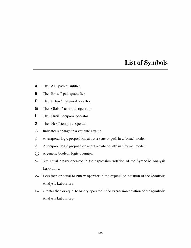
List of Symbols
A The “All” path quantifier.
E The “Exists” path quantifier.
F The “Future” temporal operator.
G The “Global” temporal operator.
U The “Until” temporal operator.
X The “Next” temporal operator.
∆ Indicates a change in a variable’s value.
φ A temporal logic proposition about a state or path in a formal model.
ψ A temporal logic proposition about a state or path in a formal model.⊕A generic boolean logic operator.
/= Not equal binary operator in the expression notation of the Symbolic Analysis
Laboratory.
<= Less than or equal to binary operator in the expression notation of the Symbolic
Analysis Laboratory.
>= Greater than or equal to binary operator in the expression notation of the Symbolic
Analysis Laboratory.
xix
Chapter 1
Human-automation Interaction
and Formal Verification∗
Complex, safety-critical systems involve the interaction of automated devices and goal-
oriented human operators in a dynamic environment. Failures in such systems are often
not due to a single component, but rather elements of the system (including human oper-
ators) interacting in unexpected ways. The human-automation interaction is particularly
important to the operation of safety critical systems as poor human-automation interaction
has contributed to failures in complex systems in a number of domains including aviation
[12, 80, 105], process control [146], and medicine [125]. For example human-automation
interaction has played an important role in the crashes of American Airlines Flight 965
[126] and China Air 140 [168]; the grounding of the Royal Majesty cruise ship [144]; the
disaster at Three Mile Island [158]; and the death of medical patients with the Therac-25
[130].
Human factors researchers have developed methods for characterizing, analyzing, and
experimenting with human-automation interaction in order to help make automated sys-
tems safe for human work. Computer science researchers have developed mathematically
∗This chapter is derived from [32]
1

Chapter 1. Human-automation Interaction and Formal Verification 2
robust modeling languages, algorithms, and methods for finding computer hardware or
software design flaws, even those resulting from the interaction of concurrent processes.
Formal methods encompass one such set of technologies. Both human-automation in-
teraction and formal methods are discussed next to set the stage for a discussion of the
intersection of these two fields.
1.0.1 Human-automation Interaction
The field of human-automation interaction is concerned with the design of automated sys-
tems to facilitate safe, human work [171]. Problems with human-automation interaction
can occur for a number of different reasons. Automation can be brittle [176] in that the
device automation and/or the human-device interface does not work correctly, does not
perform as efficiently, or does not behave as intended under certain environmental or op-
erational conditions (as was the case in the crash Air France Flight 296 [50]). These is-
sues arise because operational conditions or device behavior were not anticipated by the
designer; the device automation design was simplified due to schedule, economic, or tech-
nological limitations; or the device automation and/or human-device interface were not
implemented in accordance with the design [176].
Human-device interfaces may not provide enough feedback about the state of the de-
vice automation [143] and/or the human operator may not properly understand how the
automation works [165]. This mode confusion, where the human operator is unable to
keep track of the state or mode of the device automation, is dangerous because it can re-
sult in automation surprise, where the operator’s situation awareness is disrupted by the
device automation behaving in an unexpected way [151, 165]. Further, mode confusion
can lead to the human operator either performing inappropriate actions (errors of commis-
sion) or omitting necessary ones (errors of omission) [165]. Thus, operators of complex,

Chapter 1. Human-automation Interaction and Formal Verification 3
automated systems must work to maintain mode awareness in order to avoid such errors
[71]: a task that can be very difficult for human operators given the large number of mode
combinations, variety of behaviors a given mode can exhibit, and the range and quantity of
information displayed in some systems [165].
As systems become more automated, this can change the tasks of the human operator:
where he supervises the system rather than control it directly. In such situations, human
operators may not have been trained in the tasks necessary to administer the automation
[86]. They may fixate on a specific task while neglecting others, such as passively mon-
itoring the system [11, 141, 166, 170, 183]. They may also alter their task behavior such
that they become too dependent on automation (a condition known as automation bias) and
therefore acquire and evaluate system information less vigilantly [140, 152].
Issues can also arise as a result of incompatibilities between the behavior of the device
(both its automation and human-device interface) and the cognition of the human operator.
Many erroneous human behaviors have predictable cognitive causes [159] which can re-
late to human working memory, human knowledge, human perception, or human physical
coordination. It is possible to prevent some human errors through changes to the behavior
of the device’s automation and human-device interface [22, 45, 61, 62].
Thus, problems with human-automation interaction can arise as a result of interactions
between the different elements that make up the system: the goals, cognition, and task
behaviors of the human operator; the automated system and its human-device interface;
and the constraints imposed by the operational environment. Researchers have addressed
these issues from different directions. Cognitive work analysis is concerned with identify-
ing constraints in the operational environment that shape the mission goals of the human
operator [179]; cognitive task analysis is concerned with describing how human operators
normatively and descriptively perform goal oriented tasks when interacting with an auto-
mated system [124, 167]; and modeling and analytic frameworks use this information to
Chapter 1. Human-automation Interaction and Formal Verification 4
make predictions about human performance [123], look for discrepancies between human
mental models and device automation behavior [69], and design human-device interfaces
that reveal accurate device and environmental information while requiring reduced human
operator cognitive effort to interpret [179].
1.0.2 Formal Methods
Formal methods are a set of “well defined” mathematical languages and techniques for
the modeling, specification, and verification of systems [182]. Systems (often computer
software or hardware) are modeled using mathematically based languages, specifications
are formulated to describe desirable system properties, and a verification process math-
ematically proves whether or not the model satisfies the specification. Formal methods
have been used successfully in a number of applications, especially computer hardware
and software. While there are a number of different ways in which models can be both
manually and automatically verified, two particular computer software technologies, auto-
mated theorem provers and model checkers, have proven useful for the formal verification
of large complex systems.
Theorem proving is a deductive technique that closely resembles the traditional pencil-
and-paper proof activity: from a set of axioms, using a set inference rules, one builds
theories and proves theorems to verify correctness claims about the system under investi-
gation, with the help of a proof assistant program. While theorem proving cannot be fully
automated in practice for the most expressive logics (such as higher order logics), some
smaller fragments are more amenable to mechanized proofs. Satisfiability (SAT) solvers
[64] and satisfiability modulo theories (SMT) solvers [66] are equipped with powerful de-
cision procedures able to solve very complex problems from areas such a propositional
logic and linear algebra.

Chapter 1. Human-automation Interaction and Formal Verification 5
Model checking is a highly-automated approach used to verify that a formal model of
a system satisfies a set of desired properties (a specification) [56]. A formal model de-
scribes a system as a set of variables and transitions between variable states. Specification
properties are usually represented in a temporal logic (discussed below) using the formal
system model variables to construct propositions. Verification is performed automatically
by exhaustively searching a system’s state space in order to determine if these propositions
hold. If there is a violation, an execution trace called a counterexample is produced. This
counterexample depicts a model state (the value of the model’s variables) corresponding to
a specification violation along with a list of the incremental model states leading up to the
violation.
A temporal logic is a set of rules and symbols that allows time to be expressed and
reasoned about as part of a logical framework: where time is represented by a sequence
of states [79]. For model checking purposes, a temporal logic formula is composed of
boolean propositions about the model variables and modal operators. Modal operators
usually specify the temporal relationships between propositions. The two most common
temporal logics (Linear Temporal Logic (LTL) and Computation Tree Logic (CTL)) make
use of the modal operators described in Table 1.1. There are a variety of different specifi-
cation languages and/or modal logics of which these operators represent the most common
concepts. See Emerson [79] for more detail.
1.0.3 Analysis Types to Date
Because both human factors and formal methods are concerned with the engineering of
robust systems that will not fail under realistic operating conditions, researchers continue
to merge techniques from the two fields in order to use the powerful verification techniques
offered by formal methods to analyze human-automation interaction. This chapter next
Chapter 1. Human-automation Interaction and Formal Verification 6
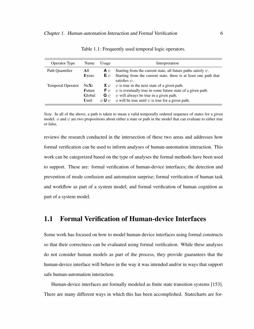
Table 1.1: Frequently used temporal logic operators.
Operator Type Name Usage Interpretation
Path Quantifier All A ψ Starting from the current state, all future paths satisfy ψ.Exists E ψ Starting from the current state, there is at least one path that
satisfies ψ.Temporal Operator NeXt X ψ ψ is true in the next state of a given path.
Future F ψ ψ is eventually true in some future state of a given path.Global G ψ ψ will always be true in a given path.Until φ U ψ φ will be true until ψ is true for a given path.
Note. In all of the above, a path is taken to mean a valid temporally ordered sequence of states for a givenmodel. φ and ψ are two propositions about either a state or path in the model that can evaluate to either trueor false.
reviews the research conducted in the intersection of these two areas and addresses how
formal verification can be used to inform analyses of human-automation interaction. This
work can be categorized based on the type of analyses the formal methods have been used
to support. These are: formal verification of human-device interfaces; the detection and
prevention of mode confusion and automation surprise; formal verification of human task
and workflow as part of a system model; and formal verification of human cognition as
part of a system model.
1.1 Formal Verification of Human-device Interfaces
Some work has focused on how to model human-device interfaces using formal constructs
so that their correctness can be evaluated using formal verification. While these analyses
do not consider human models as part of the process, they provide guarantees that the
human-device interface will behave in the way it was intended and/or in ways that support
safe human-automation interaction.
Human-device interfaces are formally modeled as finite state transition systems [153].
There are many different ways in which this has been accomplished. Statecharts are for-
Chapter 1. Human-automation Interaction and Formal Verification 7
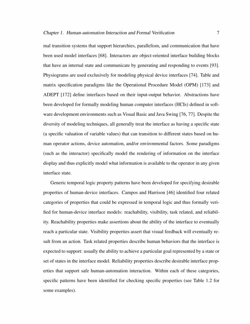
mal transition systems that support hierarchies, parallelism, and communication that have
been used model interfaces [68]. Interactors are object-oriented interface building blocks
that have an internal state and communicate by generating and responding to events [93].
Physiograms are used exclusively for modeling physical device interfaces [74]. Table and
matrix specification paradigms like the Operational Procedure Model (OPM) [173] and
ADEPT [172] define interfaces based on their input-output behavior. Abstractions have
been developed for formally modeling human computer interfaces (HCIs) defined in soft-
ware development environments such as Visual Basic and Java Swing [76, 77]. Despite the
diversity of modeling techniques, all generally treat the interface as having a specific state
(a specific valuation of variable values) that can transition to different states based on hu-
man operator actions, device automation, and/or environmental factors. Some paradigms
(such as the interactor) specifically model the rendering of information on the interface
display and thus explicitly model what information is available to the operator in any given
interface state.
Generic temporal logic property patterns have been developed for specifying desirable
properties of human-device interfaces. Campos and Harrison [46] identified four related
categories of properties that could be expressed in temporal logic and thus formally veri-
fied for human-device interface models: reachability, visibility, task related, and reliabil-
ity. Reachability properties make assertions about the ability of the interface to eventually
reach a particular state. Visibility properties assert that visual feedback will eventually re-
sult from an action. Task related properties describe human behaviors that the interface is
expected to support: usually the ability to achieve a particular goal represented by a state or
set of states in the interface model. Reliability properties describe desirable interface prop-
erties that support safe human-automation interaction. Within each of these categories,
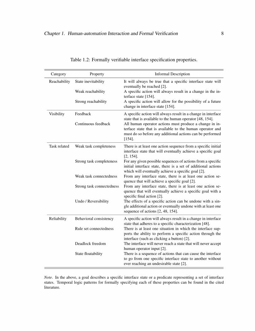
specific patterns have been identified for checking specific properties (see Table 1.2 for
some examples).
Chapter 1. Human-automation Interaction and Formal Verification 8
Table 1.2: Formally verifiable interface specification properties.
Category Property Informal Description
Reachability State inevitability It will always be true that a specific interface state willeventually be reached [2].
Weak reachability A specific action will always result in a change in the in-terface state [154].
Strong reachability A specific action will allow for the possibility of a futurechange in interface state [154].
Visibility Feedback A specific action will always result in a change in interfacestate that is available to the human operator [48, 154].
Continuous feedback All human operator actions must produce a change in in-terface state that is available to the human operator andmust do so before any additional actions can be performed[154].
Task related Weak task completeness There is at least one action sequence from a specific initialinterface state that will eventually achieve a specific goal[2, 154].
Strong task completeness For any given possible sequences of actions from a specificinitial interface state, there is a set of additional actionswhich will eventually achieve a specific goal [2].
Weak task connectedness From any interface state, there is at least one action se-quence that will achieve a specific goal [2].
Strong task connectedness From any interface state, there is at least one action se-quence that will eventually achieve a specific goal with aspecific final action [2].
Undo / Reversibility The effects of a specific action can be undone with a sin-gle additional action or eventually undone with at least onesequence of actions [2, 48, 154].
Reliability Behavioral consistency A specific action will always result in a change in interfacestate that adheres to a specific characterization [48].
Rule set connectedness There is at least one situation in which the interface sup-ports the ability to perform a specific action through theinterface (such as clicking a button) [2].
Deadlock freedom The interface will never reach a state that will never accepthuman operator input [2].
State floatability There is a sequence of actions that can cause the interfaceto go from one specific interface state to another withoutever reaching an undesirable state [2].
Note. In the above, a goal describes a specific interface state or a predicate representing a set of interfacestates. Temporal logic patterns for formally specifying each of these properties can be found in the citedliterature.

Chapter 1. Human-automation Interaction and Formal Verification 9
This work has been extended to heuristically assess usability using formal verification
or the output of formal verifications. Hussey et al. [106] identified four usability properties
(from [135]) that could be evaluated in this way: task efficiency, reuse, robustness, and
flexibility. Task efficiency describes how efficiently a human operator can perform a task
as measured by the number of actions taken to reach a goal state (information that can by
extracted from a counterexample). An interface that supports reuse will allow human oper-
ators to achieve multiple goals using similar behaviors. This has been formally measured
by comparing execution traces that achieve different goals and looking for shared action se-
quences between them. An interface that is robust will help prevent human operators from
making errors and will allow them to recover should one occur. This has been evaluated
by formally verifying properties such as deadlock freedom, state floatability, and undo/re-
versibility (Table 1.2). A flexible system allows the human operator to achieve goals in
different ways, formally measured by the number of alternate action sequences the human
operator can use to achieve a goal.
Kamel and Aït-Ameur [117] showed how four usability properties (originally from
[59]) specific to multimodal human-device interfaces could be evaluated formally: com-
plementarity, assignation, redundancy, and equivalence. Complementarity asserts that the
human operator will be able to reach a given state from a specific initial state using dif-
ferent modalities. A modality can be considered assigned to a specific state (assignation)
if it is the only modality capable of reaching that interface state. Two or more modalities
are equivalent if both allow the interface to reach a specific state. Two or more modalities
are redundant if they are equivalent and can be used in parallel to reach a specific state.
Kamel et al. [118] also provided temporal logic patterns for verifying the “adaptability” of
a multimodal interface: for a give initial state (which may encompass a condition where a
particular modality is not available), the human operator will always be able to eventually
find a way to reach a goal state.

Chapter 1. Human-automation Interaction and Formal Verification 10
1.2 Formal Verification and Mode Confusion
Researchers have investigated how formal verification can predict and help prevent mode
confusion and automation surprise.
1.2.1 Using Formal Verification to Identify Mode Confusion
There are several general approaches for using formal verification to detect potential mode
confusion. The first explicitly models the device automation’s behavior along with the
human operator’s abstracted mental model of how that automation works. The two mod-
els are then checked (either manually or using model checking) to find inconsistencies
between the two models: when the human operator’s mental model state does not match
the automation model state. Degani, Heymann, Oishi and colleagues [67, 68, 147, 148]
showed how inconsistencies could be algorithmically discovered between state chart rep-
resentations of the human operator’s mental model and device automation in a variety of
applications including an aircraft autopilot [68], a cruise control system [67], and an air-
craft auto-land system [147]. Sherry et al. [174] used matrix-based representations of both
the device automation’s input-output behavior and the human operator’s mental model of
that input-output behavior and showed how they could be algorithmically compared to find
inconsistencies for an aircraft’s mode control panel. These types of analyses have be per-
formed automatically using model checkers. Rushby et al. [163, 164] used Murφ [73] and
Buth [41] used FDR2 [85] to find known mode issues with the MD-88 autopilot.
Another approach assumes a formal model of the human-device interface and the de-
vice automation. These models are systematically searched for display conditions and
automation behaviors hypothesized to cause mode confusion. Leveson et al. [131] showed
how system requirements modeled using state machine languages could be systematically
examined for such properties. They illustrated their method with a robot control system.
Chapter 1. Human-automation Interaction and Formal Verification 11
This process has been automated using a variety of model checker and automated theo-
rem provers [42, 116, 134] to find potential mode confusion problems in a flight guidance
system. Campos and Harrison [47] showed how human operator expectations about the be-
havior of a system (an aircraft mode control panel) could be encoded in temporal logic, and
violations of those expectations could be found using the Symbolic Model Verifier (SMV)
[138] model checker for a formal system model consisting of a human-device interface
(written using interactors) and a device automation model.
A third approach encodes the human operator’s knowledge about how he accom-
plishes goals with the system through the human-device interface. This is accompanied
by a human-device interface and device automation model. All are checked for condi-
tions where the interface will not allow the human-operator to accomplish any given goal.
Wheeler [181] illustrated how such a method could be performed manually for an alarm
clock example. Bredereke and Lankenau[36, 37] automated this type of evaluation using
Communicating Sequential Processes (CSP) [99] and the FDR2 model checker [85]. Do-
ing this, they were able to find a number of potential mode confusion issues with an electric
wheel chair. Javaux [108] showed how implicit learning could be used to model how the
knowledge represented in a human operator’s mental model (modeled formally) degrades
over time due to a lack of repeated exposure to all of the automated device’s modes. Javaux
showed how this can lead to mental models that facilitate mode confusion and automation
surprise in an autopilot system.
1.2.2 Generating Human-device Interfaces that Prevent Mode
Confusion
Researchers have proposed ways of generating human-device interfaces that do not exhibit
properties associated with mode confusion. These methods assume that the human opera-
Chapter 1. Human-automation Interaction and Formal Verification 12
tors must have the information necessary to maintain a correct mental model through the
human-device interface. Thus, a mental model representing an abstraction of the system’s
device automation that does not facilitate mode confusion becomes a specification for the
information content and behavior of the human-device interface. Crow et al. [60] discussed
how mental models constructed through results from questionnaires given to human opera-
tors can be progressively abstracted and/or refined and checked with a model checker until
a “safe minimal mental model” is found: the least complex mental model that does not
facilitate mode confusion. Heymann and Degani [97] proposed an algorithmic means of
achieving such a model. First, a state chart representation of the system’s automation is
constructed. Then, each state is assigned to one of several specification classes: aggregate
states that the analyst hypothesizes the human operator must distinguish between. This
model is then systematically reduced by combining states within specification classes in
a way that avoids inconsistencies indicative of mode confusion. Combéfis and Pecheur
[57] showed how such a process could be performed automatically without the need for
specification classes.
1.3 Formal Verification and Task Analytic Models
Task analytic models are generated as part of a task analysis and can be used to model
human task behavior as sequences of activities with respect to the fulfillment of goals.
Task analytic models do not encompass sophisticated models of human cognition, and
thus are not concerned with modeling cognitive concepts such as human attention and the
mechanisms involved in human long- and short-term memory. They can, however, model
abstractions of these in order to model human behavior as a simple input-output system
where inputs can come from the human mission, the operation environment, or human
device interfaces; and outputs are human actions.
Chapter 1. Human-automation Interaction and Formal Verification 13
These models have been used in the evaluation of single and multiple operator systems
for a variety of purposes including intent inferencing [40], usability evaluation [110, 129],
intelligent tutoring [53], timing analysis of human tasks [110], alerting systems [16], and
controlling agents in simulations [87]. Because of their widespread use, researchers have
attempted to use formal methods to verify that the human behavior encompassed by task
analytic models will always accomplish the desired goals and/or avoid dangerous system
operating conditions. Extensions of this work allow erroneous human behavior to be in-
corporated into task models so that its impact can be evaluated as part of the formal verifi-
cation.
1.3.1 Formal Verification with Task Analytic Models of Normative
Human Behavior
Some researchers have modeled human tasks in the native formal notation utilized by the
analysis package they are employing. Degani et al. [70] incorporated human task mod-
els into state chart models of a human-device interface and used them to explore human
operator behavior during an irregular engine-start on an aircraft. Basnyat et al. [14, 15]
used a Petri net-based formalism called Interactive Cooperative Objects (ICO) to model
human task behavior as part of larger system models (a waste fuel delivery plant and a
satellite control system) to verify properties critical to the system’s safe operation. Reso-
lutions to discovered problems came in the form of barrier systems to monitor the system
and prevent it from transitioning to unsafe states [14] or through modification to operator
training materials [15]. Gunter et al. [89] encoded patterns of human task behavior into
CSP concurrently with system and environment models (also encoded in CSP) to verify
safety properties of a portable Automated Identification and Data Capture (AIDC) device
used to identify and record data about patients and equipment in the hospital. They showed
Chapter 1. Human-automation Interaction and Formal Verification 14
that a "protection envelope" could be incorporated into the system’s automation to ensure
that the modeled normative human task behavior would never result in situations where
incorrect or corrupted data could be entered into the AIDC device.
To facilitate model development and analyses that make use of task analytic models,
researchers have used task analytic modeling notations to model human tasks which are
then translated into the needed formalism. Palanque et al. [150] showed how task models
written in User Action Notation (UAN) [94] could be translated into ICO and used to
verify task behaviors for interacting with an automated teller machine (ATM). Fields [82]
developed a custom notation for modeling hierarchies of activities in human tasks along
with the temporal relationships between them. Aït-Ameur et al. [3, 4] and Paternò et
al. [155, 157] have translated ConcurTaskTrees [156] into formal models and performed
formal verification with larger system models. Aït-Ameur’s work used a theory prover
(called event B) to verifying human interaction with a software dialog box for converting
currencies. Paternò et al. translated CTT models of multiple human operators managing
runway traffic into LOTOS [78] and then into a formal model where it could be checked as
part of a system model encompassing the behavior of the interface, its automation, and the
environment being managed.
1.3.2 Formal Verification with Models of Erroneous Human Behavior
Rather than look for specification violations that occur with normative human behavior
models, Fields [82], [17], and Bolton and Bass et al. [25, 34] have investigated how pat-
terns of erroneous behavior (based on the phenotypes of erroneous actions [100]) can be
manually incorporated into formal task analytic models. These models could then be inte-
grated with the analyses described above in order to use formal verification to investigate
whether these errors impact the fulfillment of specification properties.
Chapter 1. Human-automation Interaction and Formal Verification 15
1.4 Formal Verification and Cognitive Models
Instead of modeling human tasks, researchers have modeled human cognition as part of
a formal system model for use in formal verification. The goal is to model the cognitive
process the operator employs to decide what actions he will use to interact with the system.
These methods let the analyst to formally verify that the system will always allow the
operator to achieve his goals with a set of cognitive behaviors. These methods can identify
situations where the human operator fails to achieve his desired goals or drives the system
into dangerous operating conditions.
Lindsay and colleagues [51, 128, 132] have investigated the use of the Operator Choice
Model (OCM) in such an analysis. The OCM describes the process human operators use
to scan or search human-device interfaces for information, determine if that information
is worthy of additional interest, decide how to proceed in light of the assessed informa-
tion, and execute a plan of actions. This method was used to model the human operator’s
cognitive process for identifying and attempting to resolve conflicts in a simple air traffic
control task. Patterns of human behavior were encoded into temporal logic and a model
checker was used to check that these behaviors were cognitively valid (were compatible
with their cognitive model) and would not result in the operator failing to resolve a conflict
or accidentally creating a conflict between aircraft.
Blandford, Curzon, and colleagues have focused on creating Programmable User Mod-
els (PUMs) [184] that capture the knowledge and cognitively plausible behavior that an
operator might use when interacting with an automated system and implementing them as
part of a formal system model [21, 23, 44]. PUMs encompass the goals the operator wishes
to achieve with the system, his beliefs and knowledge about the operation of the system, the
information available to him from the human-device interface, and the actions he can use
to interact with the system. When executing, the human operator model must use knowl-
Chapter 1. Human-automation Interaction and Formal Verification 16
edge about the system and the currently available information to select actions to fulfill its
goals. Such models have been used with human initiated systems (where system behavior
is solely driven by its human operator) [23] and evaluated using formal verification with
both theorem provers [43] and model checkers [160].
These formal PUM analyses have been used to obtain different insights about systems.
Butterworth et al. [43] showed how specification properties related to system safety, live-
ness, and usability could be investigated using PUMs and formal verification for a simple
web browsing task. Butterworth et al. [43] used PUMs and formal verification with the
same application to identify the type of knowledge a human operator requires in order to
successfully fulfill his goals. PUMs and formal verification have been used to identify cog-
nitively plausible errors based on a human operator model interacting with an automated
system. These include repetition of actions, omission of actions, committing actions too
early, replacing one action with another, performing one or more actions out of order, and
performing an unrelated action [61]. Means of identifying post-completion errors (special
types of omission errors in which the operator forgets to perform actions that occur after the
completion of a high level goal) have also been identified and illustrated using a model of
a vending machine [62]. Design rules were applied to address these errors, and their effec-
tiveness was evaluated using the same formal verification process [61, 62]. Work has also
investigated using PUMs to model different classes of human operator (expert vs. novice)
[63] in order to investigate when different types of operators may perform different errors
when interacting with an ATM. Keystroke-level timing analysis (similar to that used by
KLM-GOMS [110]) have also been added into their framework and used to evaluate tim-
ing performance of a human operator interacting with the ATM [162]. PUM models have
also been extended so that formal verification can investigate how humans might make er-
rors due to issues related to salience, cognitive load, and cognitive interpretation of spatial
cues [160, 161], illustrated with the same ATM model. Basuki et al. [19] used heuristics
Chapter 1. Human-automation Interaction and Formal Verification 17
for modeling human operator habituation, impatience, and carefulness and showed how
they could be used to find human errors for interacting with the vending machine model
from Curzon and Blandford [62].
1.5 Limitations of Current Techniques and Technologies
1.5.1 Limitations of Formal Verification
Despite its power, there are a number factors which limit what formal verification can do.
1.5.1.1 Limitations of Model Checking
One of the challenges facing model checking verification is the state explosion problem.
As the complexity of the modeled system increases, the memory and time required to store
the combinatorially expanding state space can easily exceed the available resources. One
way this has been addressed is through the development of extremely efficient means of
representing a system’s state space, referred to as symbolic model checking [39]. Other
techniques allow select portions of the state space to be searched without compromising
the accuracy of the verification. The best known of these depend on partial order reduction
[103], symmetry [88] and abstraction techniques such as abstract interpretation [58] and
counterexample-guided abstraction refinement [55].
A second major limitation of model checking is the expressive power of its modeling
formalisms. Traditional model checking is applied to systems that can be modeled with
discrete variables. However, complex systems can have continuous quantities. While the
field of hybrid systems has been developed to address this issue [95], current techniques
can handle systems models with no more than a half-dozen continuous variables. With
respect to the modeling of time, discrete-state models can be augmented with a set of
Chapter 1. Human-automation Interaction and Formal Verification 18
clocks [96]. While this technique can be used to model clock synchronization problems in
digital systems, only very simple models can be fully verified.
One of the most compelling outputs of a model checker is a counterexample: an ex-
ecution trace illustrating exactly how a specification was violated. In most analysis envi-
ronments this is a list of the model variables and the values they assume at each step in the
execution trace. This output can be cumbersome to interpret. There have been a few at-
tempts to remedy this problem. Traviando [119] uses message sequence charts to visualize
model checker counterexamples. Loer and Harrison [133] used a table to display coun-
terexample information, where changes in variable values were highlighted. A number of
animations and sequence diagrams have also been discussed [3, 133].
1.5.1.2 Limitations of Automated Theorem Proving
In principle, theorem proving does not suffer from the same limitations as model checking.
However, theorem proving is not a fully automated process: the analyst guides the proof
while exploiting automation to reuse routine proof techniques. The more expressive the
logic used to model and reason about the system, the less automation is possible. Thus,
theorem proving requires significant effort by highly trained experts who guide the verifi-
cation process. Further, because the proof process must be guided, theorem proving is less
likely to find emergent features that are not anticipated by the analyst.
1.5.1.3 Examples in the Literature
These limitations are reflected in the covered literature as the majority of the applications
of formal verification in human-automation interaction are very simple: franc to euro cur-
rency converters [3, 4], interface widgets [5, 38], automated teller machines [63, 149],
aircraft mode control panels [47, 68, 163, 174], and air conditioner programming inter-
faces [57] to name a few. Work by Bolton and Bass [27, 31] and Blandford et al. [23],
Chapter 1. Human-automation Interaction and Formal Verification 19
who both attempted to representatively model more complex systems (such as a patient
controlled analgesia (PCA) pump and calender program respectively), ultimately resorted
to a series of model compromises and abstractions in order for the verification process to
be tractable. There have also been very few attempts at evaluating hybrid systems (see
[147] and [148]).
1.5.2 Tradeoffs Between Formal Human-automation Interaction
Verification Techniques
Each of these approaches has advantages and disadvantages. The human-device interface
verification and mode confusion work does not explicitly describe human operator behav-
ior (treating them as unbounded) and thus must be used to evaluate very simple and/or
heavily abstracted representations of device automation in order to avoid being limited by
the size of the system model. Because human behavior is not explicitly modeled, these
techniques can only be used to find system conditions theorized to be preconditions to
erroneous human behavior.
The cognitive modeling work avoids some of these limitations by bounding human
behavior based on models of cognition. By explicitly modeling the cognitive processes hu-
man operators use to interact with the system, formal verification can be used to find unsafe
system operating conditions, and predict when the system facilitates erroneous behavior.
By constraining the system around plausible human behavior, higher fidelity models can
be evaluated.
The task modeling work similarly constrains operator behavior. The task analytic mod-
els used in these analyses only describe the explicit human behavior (not the cognition).
Thus processes that use them can make use of more complex system models than those
used in the cognitive modeling techniques. However, any erroneous human behavior the
Chapter 1. Human-automation Interaction and Formal Verification 20
analyst wants to consider must be manually incorporated into the task analytic models.
1.5.3 General Limitations of Formal Verification of Human-
automation Interaction
There are also several general limitations for the use of formal verification for evaluat-
ing the safe operation of human-automation interactive systems. Firstly, the task behavior
models used either rely on the formal modeling notation [14, 15, 70] or on notations not
common in the human factors literature [3, 4, 82, 155, 157] which do not support all of
the different ordinal and parallel relationships that can exists between actions in human
task behavior. Secondly, none of the existing work utilizes an architectural framework ca-
pable of allowing system models to be constructed around all of the human-automation
interaction concepts: the human task behavior, the human mission or goals, the device
automation, the human device interface, and the operational environment. Thus none of
the discussed analyses allow for easy interchange of different models of these elements in
order to perform multiple analyses while exploring a design. Thirdly, little of the discussed
literature addresses the computational limitations of the analysis techniques making it dif-
ficult for practitioners to determine the scalability of the analyses. Finally, all the work
discussed which incorporates erroneous human behavior requires either modeling cogni-
tion (which adds complexity) [51, 61, 62, 128, 132, 160, 161] or manual intervention to
apply erroneous behavior patterns to task analytic models (which may miss many potential
erroneous behaviors) [17, 82].
The remainder of this document discusses a research effort that addresses these issues.
Chapter 1. Human-automation Interaction and Formal Verification 21
1.6 Research Objectives: A Method to Evaluate the Role
of Human-automation Interaction in System Failure
1.6.1 Operation Concept
This work is focused on extending the analyses that can be performed using formal ver-
ification and task analytic models. If an analyst is interested in evaluating how human
behavior may contribute to system failure (the violation of system safety properties) then
he will want to be able to evaluate realistic normative and erroneous human behavior in
light of varying goals or missions and different system operating conditions and behav-
iors. Further, he may wish to run multiple analyses in order to assess how different human
goals or behaviors from the human affect system safety. He may also wish to evaluate
the safety implications for different human-device interfaces, device automation designs,
or environments either to evaluate different designs, operating conditions, or to identify
potential interventions that can fix problems discovered during formal verification.
An infrastructure capable of supporting these analyses should have a number of fea-
tures. It should allow task analytic models of human behavior to be represented in a way
characteristic of existing task analytic modeling constructs in order to allow task analysis
experts (mostly human factors engineers) to implement these models. Task models should
be capable of supporting the temporal orderings and parallelism from existing task model-
ing paradigms. Task models should also have a formally defined semantics which would
ensure that a model’s meaning would be unambiguous and capable of being implemented
in a formal modeling notation.
The human task behavior model should be able to be integrated with a larger system
model encompassing other system components of interest to an analyst such as human op-
erator goals or missions, device automation behavior, the human-device interface, and the

Chapter 1. Human-automation Interaction and Formal Verification 22
operational environment. Thus the task model should be capable of interfacing and coordi-
nating its behavior with the other system components. Because a human-device interface
is, by definition, the means by which a human operator can perform actions that impact the
system, the human-task behavior model should have information about the human-device
interface necessary for performing the task such as what actions the interface can receive
(such as button presses) and what information it provides.
Analyst may want to run multiple analyses using different task behavior models, human
missions, human device interfaces, device automation behaviors, or operational environ-
ments in order to evaluate different designs or to identify potential interventions that may
eliminate discovered problems. Thus the formal system model should facilitate the ability
to easily incorporate alternative configurations of any of these elements.
Because erroneous human behavior can occur in unexpected circumstances, the abil-
ity to generate erroneous human behavior for use in formal verifications is advantageous.
Thus, there should be a theoretically driven means of systematically altering the structure
or interpretation of task analytic models so that they would be capable of generating realis-
tic erroneous human behavior. This allows erroneous human behavior to be systematically
included in formal verifications with task behavior models without the need for low level
detailed cognitive models.
Task model constructs should be used to present formal verification results to analysts
so that they can be interpreted using the same representation in which the models were
developed.
Finally, because of the restrictions formal verification places on the complexity of sys-
tem models, analysts should have access to information which allows them to interpret how
task behavior modeling impacts system model complexity, and thus potentially limits what
can be formally verified.
Chapter 1. Human-automation Interaction and Formal Verification 23
1.6.2 The Method
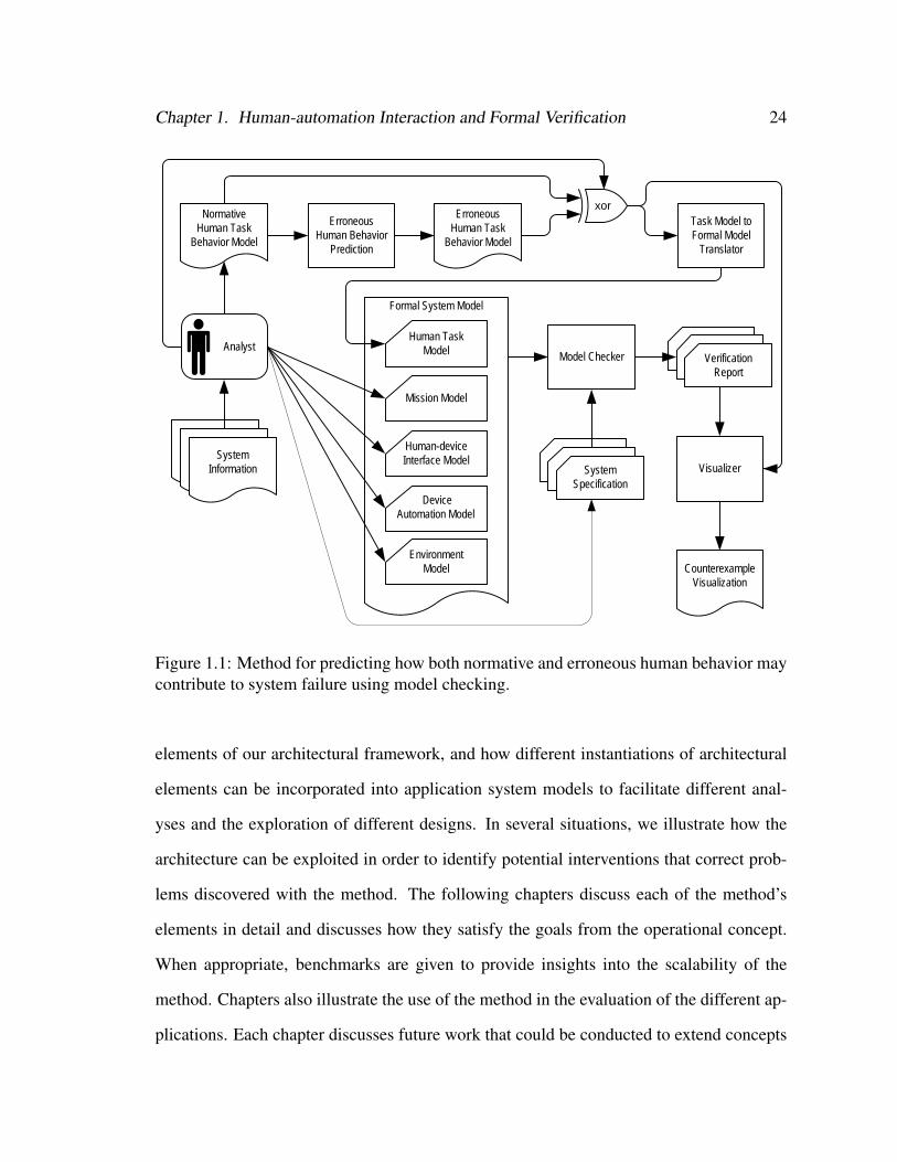
To address these issues we have developed a method (Figure 1.1) which extends the model
checking verification process. In it, a human analyst examines documentation and other
information gleaned from the evaluation of a target system. He creates models of the nor-
mative human task behavior using a novel task analytic representation. This task model
can then run through an automatic human erroneous behavior prediction process in order
to produce an erroneous human behavior model capable of generating erroneous human
behavior. The analyst can choose whether he wants to use the erroneous or normative
human behavior model in the remaining process. Our automated process, the task model
translator, then converts the chosen human task behavior model into a formal human task
model which can be incorporated into a larger formal system model. The analyst creates
(or uses existing) formal system models of the mission, human-device interface, device au-
tomation, and environment. He also creates temporal logic specifications representing the
system qualities he wants to be true. The formal system model and the system specification
are run through the model checker which produces a verification report. If a violation of a
specification is found, the report will contain a counterexample. The counterexample and
the original human task behavior model can then be processed by our automated visualizer
which illustrates the sequence of human behaviors and related system states that led to the
violation.
1.6.3 Contributions
This method is capable of both formally verifying and discovering problems in human-
automation interactive systems while incorporating models of both normative and gener-
ated erroneous human behavior. We demonstrate this with a number of different applica-
tions which show how the method can be adapted to verify systems that require different
Chapter 1. Human-automation Interaction and Formal Verification 24
NormativeHuman Task
Behavior Model
Formal System Model
Human-device Interface Model
EnvironmentModel
Model Checker
System Specification
Task Model to Formal Model
Translator
Analyst
Mission Model
Human Task Model
System Information Visualizer
Counterexample Visualization
Verification Report
Erroneous Human Behavior
Prediction
Erroneous Human Task
Behavior Model
xor
Device Automation Model
Figure 1.1: Method for predicting how both normative and erroneous human behavior maycontribute to system failure using model checking.
elements of our architectural framework, and how different instantiations of architectural
elements can be incorporated into application system models to facilitate different anal-
yses and the exploration of different designs. In several situations, we illustrate how the
architecture can be exploited in order to identify potential interventions that correct prob-
lems discovered with the method. The following chapters discuss each of the method’s
elements in detail and discusses how they satisfy the goals from the operational concept.
When appropriate, benchmarks are given to provide insights into the scalability of the
method. Chapters also illustrate the use of the method in the evaluation of the different ap-
plications. Each chapter discusses future work that could be conducted to extend concepts
Chapter 1. Human-automation Interaction and Formal Verification 25
and technologies discussed in the chapter.
Chapter 2 introduces the EOFM: a hierarchical, generic, platform independent, XML-
based, task analytic modeling language. We present the syntax of EOFM which incorpo-
rates features from Operator Function Model [139] and extends them with additional task
sequencing options. The EOFM’s visual syntax is illustrated using an example of program-
ming a digital alarm clock. We also present the EOFM’s formal semantics which represents
a mathematically based, unambiguous interpretation of the meaning of the EOFMs model-
ing constructs. The potential future extensions of the language are discussed.
Chapter 3 discusses the goals and rationale behind the formal system modeling ar-
chitectural framework which was composed of independent models of the human mission,
human task behavior, human-device interface, device automation, and operational environ-
ment. The chapter discusses the coordination that is required to allow EOFM task models
to interact with other components of the architecture. Finally it presents a PCA pump ex-
ample which includes models of the operator’s mission and task behavior as well as device
automation and the human-device interface. These verification procedures demonstrate the
use of our method to verify a human-automation interactive system using both an uncon-
strained human task behavior model and normative human task behavior. The PCA pump
model required multiple revisions before it was small enough to be fully verified. This
application represents a realistic upper bound on the complexity of models our method
can handle for the computation resources available to us. This application’s use in the
analyses also demonstrates a tradeoff between model complexity and verification time be-
tween unconstrained human operator models and that controlled by formal representations
of EOFM task behavior.
Chapter 4 shows how the EOFM’s formal semantics were used to construct an auto-
mated process for translating an instantiated EOFM into the formal modeling language of
SAL. This allows instantiated EOFMs to be automatically incorporated into a formal sys-
Chapter 1. Human-automation Interaction and Formal Verification 26
tem model which can be used in formal verification. We use formal verification to validate
that the translator is producing SAL code that conforms to the EOFM’s formal seman-
tics (see Appendix B). We also report on an evaluation of the scalability of the translation
algorithm. We then present an automobile cruise control example to illustrate how an in-
stantiated EOFM can be integrated into a larger system model that includes the human op-
erator’s mission, device automation, human-device interface, and operation environment.
Using our method, we were able to identify a problem with the system and formally verify
that a solution which, with modifications to the human-device interface and task behavior
model, corrected it.
While there is a plethora of literature on erroneous human behavior (see [115]), the
two most prominent perspectives are those offered by Hollnagel [100] and Reason [159]:
where Hollnagel classifies erroneous human behavior based on how the observable man-
ifest (their phenotypes) and Reason classifies them based on their cognitive causes (their
genotypes). Chapters 5 and 6 show how these two perspectives on erroneous human behav-
ior can be used to generate erroneous human behavior by either permuting an instantiated
EOFM’s task structure to generate Hollnagel’s phenotypes using the instantiated EOFM’s
information about the human device interface (Chapter 5) or by modifying the formal se-
mantics of the instantiated EOFM to generate Reason’s attentional slips (Chapter 6). In
both chapters, the error generation process is described and the chapter discusses how the
erroneous human behavior generation was incorporated as an option to be automatically
generated by the EOFM to SAL translator. Each chapter also presents an application that
illustrate the types of system problems that can be found using the particular erroneous be-
havior generation technique (a radiation therapy machine in Chapter 5 and the PCA pump
in Chapter 6). Both examples included models of the operator’s mission and task behavior
as well as device automation and the human-device interface. In both applications, safety
properties verified to true when the normative human behavior model was used. However,
Chapter 1. Human-automation Interaction and Formal Verification 27
violations were discovered with the system models containing the generated erroneous hu-
man behavior models. In Chapter 5 this was corrected by changing the device automation.
In Chapter 6 the correction occurs through changes to the human-device interface. Chapter
6 discusses the tradeoffs between the two erroneous behavior generation techniques.
In Chapter 7, we present a novel visualizer which allows counterexamples produced
by SAL for models utilizing translated EOFM task behavior models using the EOFM’s
visual notation, the architectural framework, and concepts from general counterexample
visualizers. The chapter discusses the rationale and operation concept for the visualizer
and presents a design prototype. The chapter then demonstrates how the visualizer com-
municated information relevant to diagnosing problems in the cruise control application,
the radiation therapy machine, and the PCA pump. Thus the chapter demonstrates the ca-
pabilities of the visualizer for diagnosing problems in formal system models containing
normative human behavior as well as both types of generated erroneous behavior.
Chapter 9 presents an extended application of the method: an aircraft on approach. This
application’s formal system model contained all elements of the architectural framework:
human mission, human task behavior, device automation, human-device interface, and en-
vironment. In this example we show how the flexibility of the method and architectural
framework can be exploited to investigate the design of a system by interchangeably using
different instances of architectural elements between analyses. In doing this, the system is
evaluated with multiple normative human task behaviors, multiple erroneous human task
behaviors, and multiple device automation behaviors. In the latter case, the analyses show
how the impact of degraded and/or erroneous automation behavior can be evaluated with
our method. In all analyses, solutions to discovered problems are discussed, some of which
involve formal verifications with models containing new or modified human missions, au-
tomation behaviors, or human task behaviors.
Finally Chapter 9 discusses the contributions of this work and outlines how future work

Chapter 1. Human-automation Interaction and Formal Verification 28
could evaluate and extend the method. It also discusses how the formal verification of
human-automation interaction could be further developed in general.
Chapter 2
The Enhanced Operator Function Model:
Syntax and Formal Semantics∗
When designing for human-automation interaction, human factors engineers generally do
not use formal models, but rather task analytic methods to represent human operator be-
haviors. Task analytic models represent descriptive and normative human behavior for in-
teracting with an automated system as sequences of activities with respect to the fulfillment
of goals [124, 167]. These types of models have been used in the specification, implemen-
tation, and analysis of single- and multi-operator systems [16, 28, 53, 87, 110, 129, 178].
Such models are heterarchical as there can be a number of independent goals and strategies
to achieve them. They can be hierarchical in that goals decompose into lower level activ-
ities and ultimately atomic actions. Further, conditions specify constraints under which
activities and actions can execute. Logical operators can also be used to control how many
activities or actions can execute and what temporal relationship exists between them. Infor-
mation from external sources (the operational environment, the human operator’s mission,
human-device interfaces, other human team members, etc.) can be used in the definition
of conditions.∗This chapter is derived from [28] and [33]
29
Chapter 2. The Enhanced Operator Function Model: Syntax and Formal Semantics 30
This chapter present the EOFM language, its syntax, and its formal semantics all of
which are used in a variety of examples in subsequent chapters.
2.1 Enhanced Operator Function Model
There are several task analytic modeling paradigms such as Operator Function Model
[139], ConcurTaskTrees (CTTs) [154], hazard networks [16], User Action Notation (UAN)
[98], and several varieties of Goals, Operators, Methods, and Selection rules (GOMS)
[110]. Collectively these techniques encompass the following features [28]:
• Activities can be modeled as sequences of actions or as part of more complex hier-
archies of activities which can ultimately decompose into atomic actions.
• Observable human actions (such as pushing a button, turning a wheel, or flipping a
switch) are supported by all techniques but some also support human cognitive or
perceptual actions (such as remembering a number or noticing an alarm).
• Different cardinalities for how many sub-activities or actions can execute in a given
decomposition: zero or more, one or more, exactly one, or all.
• Different temporal orders that control when sub-activities and actions can execute in
relation to each other: in sequence with no overlap in any order, in sequence with no
overlap in a particular order, synchronized, or executed in parallel with any potential
overlapping or interleaving.
• Different ways to represent strategic knowledge and/or conditions that control when
activities can execute, when they are completed, and when they can repeat.
• Different analysis environments and platforms.
Chapter 2. The Enhanced Operator Function Model: Syntax and Formal Semantics 31
• Support for graphical notations that help to convey the modeled behavior.
By extending the OFM [139], the Enhanced Operator Function Model (EOFM) [28]
is a generic task analytic modeling language to support the features described above. The
OFM supports a visual and object-oriented means of representing task models. It uses
state and derived variables to specify model behavior including its handling of input and
output. It models goal-level behaviors as activities. Each activity may include conditions
that describe under what conditions it can be undertaken. Activities are decomposed into
lower-level sub-activities and, finally, actions. Operators on each decomposition specify
the cardinality of and the temporal relationships between the sub-activities or actions. The
EOFM standardizes the type of conditions that modify activities and supports the full cross
set of the cardinalities and temporal orderings discussed above. The EOFM language is
XML-based, thus making it platform independent and easy to parse. A more in depth
discussion of the design decisions that went into the EOFM can be found in [28].
2.2 Language Description
The EOFM language supports modeling the human operator as an input/output system. In-
puts may come from several sources including: the human-device interface, environment,
mission goals, and other human operators. Output variables are human actions. The oper-
ator’s task model describes how human actions may be generated based on input and local
variables.
Each human operator model is a set of EOFM task models that describe goal-level
activities. Activities decompose into lower level activities and eventually atomic actions.
Decompositions are controlled by decomposition operators that specify the cardinality of
and temporal relationship between the sub-activities or actions; allowing zero or more, one
or more, exactly one, or all to execute with all of the task analytic modeling supported
Chapter 2. The Enhanced Operator Function Model: Syntax and Formal Semantics 32
options for ordered, sequential, parallel, or synchronized execution. Activities can have
preconditions, repeat conditions, and completion conditions (Boolean expressions written
in terms of input, output, and local variables as well as constants) which specify what must
be true before an activity can execute, when it can repeat execution, and what is true when
it has completed execution respectively. Atomic actions are either an assignment to an
output variable (indicating an action has been performed) or a local variable (representing
a perceptual or cognitive action). All variables are defined in terms of constants, user
defined types, and basic types; described below.
2.2.1 Syntax
The EOFM language’s XML syntax is defined using the Relax NG standard [54]. The
specification of its syntax, graphically depicted in Figure 2.1, has been modified from [28]
in order to support more standardized terminology and an XML structure that more closely
represents the EOFM graphical notation.
XML documents contain a single root node whose attributes and sub-nodes define the
document. For the EOFM specification, the root node is called eofms. The next level
of the hierarchy, has zero or more constant nodes, zero or more userdefinedtype nodes,
and one or more humanoperator nodes. The userdefinedtype nodes define enumerated
types useful for representing operational environment, human-device interface, and human
mission concepts. A userdefinedtype node is composed of a unique name attribute (by
which it can be referenced) and a string of data representing the type construction (the
syntax of which is application dependent). A constant node is defined by a unique name
attribute, either a userdefinedtype attribute (the name attribute of a userdefinedtype node)
or basictype attribute.
The humanoperator nodes represent the task behavior of the different human opera-
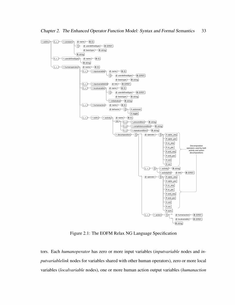
Chapter 2. The Enhanced Operator Function Model: Syntax and Formal Semantics 33file:/C:/Users/mlb4b/Documents/NetBeansProjects/HFE/examples/OFMr7a.rng <oXygen/> XML Editor
1 of 1
Start
eofms 0.. constant @ name DD ID
@ userdefinedtype DD IDREF
@ basictype DD string
DD string
0.. userdefinedtype @ name DD ID
DD string
1.. humanoperator @ name DD ID
0.. inputvariable @ name DD ID
@ userdefinedtype DD IDREF
@ basictype DD string
0.. inputvariablelink @ link DD IDREF
0.. localvariable @ name DD ID
@ userdefinedtype DD IDREF
@ basictype DD string
initialvalue DD string
1.. humanaction @ name DD ID
@ behavior autoreset
toggle
1.. eofm activity @ name DD ID
0..1 precondition DD string
0..1 completioncondition DD string
0..1 repeatcondition DD string
decomposition @ operator optor_seq
optor_par
or_seq
or_par
and_seq
and_par
ord
xor
1.. activity DD string
activitylink @ link DD IDREF
@ operator optor_seq
optor_par
or_seq
or_par
and_seq
and_par
ord
xor
sync
1.. action @ humanaction DD IDREF
@ localvariable DD IDREF
DD string
Decomposition operators used by both
activity and action decompositions
Figure 2.1: The EOFM Relax NG Language Specification
tors. Each humanoperator has zero or more input variables (inputvariable nodes and in-
putvariablelink nodes for variables shared with other human operators), zero or more local
variables (localvariable nodes), one or more human action output variables (humanaction
Chapter 2. The Enhanced Operator Function Model: Syntax and Formal Semantics 34
nodes) and one or more task models (eofm nodes). A human action (a humanaction node)
describes a single, observable, atomic act that a human operator can perform. A humanac-
tion node is defined by a unique name attribute and a behavior attribute which can have one
of two values: autoreset (for modeling a single discrete action such as flipping a switch) or
toggle (for modeling an action that must be started and stopped as separate discrete events
such as holding a button down and then releasing it).
Input variables (inputvariable nodes) are composed of a unique name attribute and
either a userdefinedtype or basictype attribute (defined as in the constant node). To support
the definition of inputs that can be perceived concurrently by multiple human operators
(for example two human operators hearing the same alarm issued by an automated system)
the inputvariablelink node allows a humanoperator node to access input variables defined
in a different humanoperator node using the same input variable name. Local variables
are represented by localvariable nodes, themselves defined with the same attributes as an
inputvariable or constant node, with an additional sub-node, initialvalue, a data string with
the variable’s default initial value.
The task behaviors of a human operator are defined using eofm nodes. One eofm node
is defined for each goal directed task behavior. The tasks are defined in terms of activity
nodes. An activity node is represented by a unique name attribute, a set of optional condi-
tions, and a decomposition node. Condition nodes contain a boolean expression (in terms
of variables and human actions) with a string that constrains the activity’s execution. The
following conditions are supported:
• precondition: criterion to start executing;
• repeatcondition: criterion to repeat the execution; and
• completioncondition: criterion to complete execution.
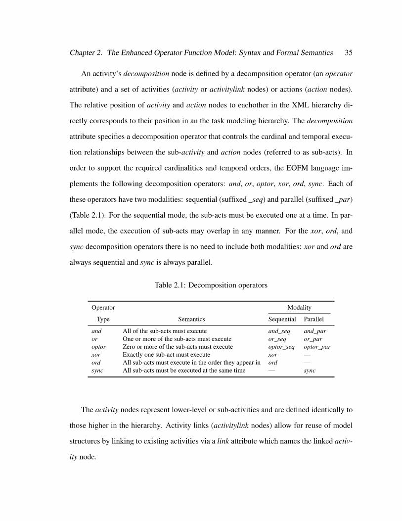
Chapter 2. The Enhanced Operator Function Model: Syntax and Formal Semantics 35
An activity’s decomposition node is defined by a decomposition operator (an operator
attribute) and a set of activities (activity or activitylink nodes) or actions (action nodes).
The relative position of activity and action nodes to eachother in the XML hierarchy di-
rectly corresponds to their position in an the task modeling hierarchy. The decomposition
attribute specifies a decomposition operator that controls the cardinal and temporal execu-
tion relationships between the sub-activity and action nodes (referred to as sub-acts). In
order to support the required cardinalities and temporal orders, the EOFM language im-
plements the following decomposition operators: and, or, optor, xor, ord, sync. Each of
these operators have two modalities: sequential (suffixed _seq) and parallel (suffixed _par)
(Table 2.1). For the sequential mode, the sub-acts must be executed one at a time. In par-
allel mode, the execution of sub-acts may overlap in any manner. For the xor, ord, and
sync decomposition operators there is no need to include both modalities: xor and ord are
always sequential and sync is always parallel.
Table 2.1: Decomposition operators
Operator Modality
Type Semantics Sequential Parallel
and All of the sub-acts must execute and_seq and_paror One or more of the sub-acts must execute or_seq or_paroptor Zero or more of the sub-acts must execute optor_seq optor_parxor Exactly one sub-act must execute xor —ord All sub-acts must execute in the order they appear in ord —sync All sub-acts must be executed at the same time — sync
The activity nodes represent lower-level or sub-activities and are defined identically to
those higher in the hierarchy. Activity links (activitylink nodes) allow for reuse of model
structures by linking to existing activities via a link attribute which names the linked activ-
ity node.
Chapter 2. The Enhanced Operator Function Model: Syntax and Formal Semantics 36
The lowest level of the task model hierarchy is represented by either observable, atomic
human actions or internal (cognitive or perceptual) ones, all using the action node. For an
observable human action, the name of a humanaction node is listed in the humanaction
attribute. For an internal human action, the valuation of a local variable is specified by
providing the name of the local variable in the localvariable attribute and the assigned
value within the node itself 1.
2.2.2 EOFM Visualization
The structure of an instantiated EOFM’s task behaviors can be represented visually as a
tree-like graph structure (an example appears in Figure 2.2) where actions are represented
by rectangular nodes and activities by rounded rectangle nodes. In these representations,
conditions are connected to the activity they modify: a precondition is represented by a
yellow, downward pointing triangle connected to the right side of the activity; a comple-
tioncondition is presented as a magenta, upward pointing triangle connected to the left of
the activity; and a repeatcondition is conveyed as a recursive arrow attached to the top of
the activity. These standard colors are used for condition shapes to help distinguish them
from each other and the other task structures. Decompositions are presented as arrows,
labeled with the decomposition operator, extending below an activity that points to a large
rounded rectangle containing the decomposed activities or actions.
2.2.3 EOFM Formal Semantics
We now formally describe the semantics of the EOFM language’s task models: explicitly
defining how and when each activity and action in a task structure executes.
1An example of an instantiated EOFM’s XML code for the automobile driver discussed in Chapter 4 canbe found in Appendix A
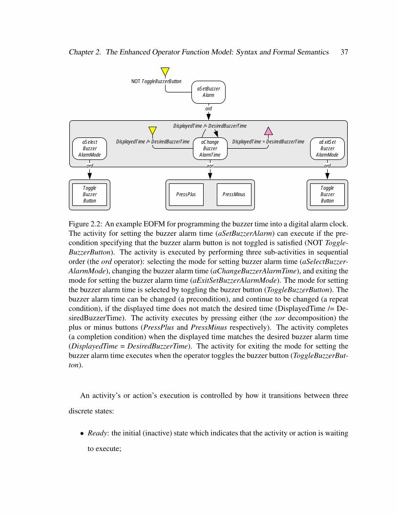
Chapter 2. The Enhanced Operator Function Model: Syntax and Formal Semantics 37
aSetBuzzerAlarm
NOT ToggleBuzzerButton
ord
aSelectBuzzer
AlarmMode
DisplayedTime = DesiredBuzzerTime
ord
ToggleBuzzerButton
aChangeBuzzer
AlarmTime
DisplayedTime /= DesiredBuzzerTime
xor
PressPlus PressMinus
aExitSetBuzzer
AlarmMode
ord
ToggleBuzzerButton
DisplayedTime /= DesiredBuzzerTime
Figure 2.2: An example EOFM for programming the buzzer time into a digital alarm clock.The activity for setting the buzzer alarm time (aSetBuzzerAlarm) can execute if the pre-condition specifying that the buzzer alarm button is not toggled is satisfied (NOT Toggle-BuzzerButton). The activity is executed by performing three sub-activities in sequentialorder (the ord operator): selecting the mode for setting buzzer alarm time (aSelectBuzzer-AlarmMode), changing the buzzer alarm time (aChangeBuzzerAlarmTime), and exiting themode for setting the buzzer alarm time (aExitSetBuzzerAlarmMode). The mode for settingthe buzzer alarm time is selected by toggling the buzzer button (ToggleBuzzerButton). Thebuzzer alarm time can be changed (a precondition), and continue to be changed (a repeatcondition), if the displayed time does not match the desired time (DisplayedTime /= De-siredBuzzerTime). The activity executes by pressing either (the xor decomposition) theplus or minus buttons (PressPlus and PressMinus respectively). The activity completes(a completion condition) when the displayed time matches the desired buzzer alarm time(DisplayedTime = DesiredBuzzerTime). The activity for exiting the mode for setting thebuzzer alarm time executes when the operator toggles the buzzer button (ToggleBuzzerBut-ton).
An activity’s or action’s execution is controlled by how it transitions between three
discrete states:
• Ready: the initial (inactive) state which indicates that the activity or action is waiting
to execute;
Chapter 2. The Enhanced Operator Function Model: Syntax and Formal Semantics 38
• Executing: the active state which indicates that the activity or action is executing;
and
• Done: the secondary (inactive) state which indicates that the activity has finished
executing.
While preconditions, repeatconditions, and completionconditions can be used to de-
scribe when activities and actions transition between these execution states, three addi-
tional conditions are required. These conditions support transitions based on the activity’s
or action’s position in the task structure, the execution state of its parent, sub-acts (activities
or actions into which the activity decomposes), and siblings (activities or actions contained
within the same decomposition).
• startcondition: implicit condition that triggers the start of an activity or action de-
fined in terms of the execution states of its parent and siblings.
• endcondition: implicit condition to end the execution of an activity or action defined
in terms of the execution state of its sub-acts.
• reset: implicit condition to reset an activity (have it return to the Ready execution
state).
For any given activity or action in a decomposition, a startcondition is comprised of two
conjuncts: one stipulating conditions on the execution state of its parent and the other on
the execution state of its siblings based on the parent’s decomposition operator, generally
formulated as:
(parent .state = Executing) ∧∧
∀siblings s
(s .state 6= Executing)
Chapter 2. The Enhanced Operator Function Model: Syntax and Formal Semantics 39
This is formulated differently in the following circumstances. If the parent’s decompo-
sition operator has a parallel modality, the second conjunct is eliminated. If the parent’s
decomposition operator is ord, the second conjunct is reformulated to impose restrictions
only on the previous sibling in the decomposition order: (prev_sibling .state = Done). If
it is the xor decomposition operator, the second conjunct is modified to enforce the condi-
tion that no other sibling can execute after one has finished:
∧∀siblings s
(s.state = Ready)
An endcondition is also comprised of two conjuncts both related to an activity’s sub-
acts. Since an action has no sub-acts, an action’s endcondition defaults to true. The first
conjunct asserts that the execution states of the activity’s sub-acts satisfy the requirements
stipulated by the activity’s decomposition operator. The second asserts that none of the
sub-acts are executing. This is generically expressed as follows:
( ⊕∀subacts c
(c.state = Done)
)∧
∧∀subacts c
(c.state 6= Executing)
In the first conjunct,⊕
(a generic operator) is to be substituted with ∧ if the activity
has the and_seq, and_par, or sync decomposition operator; and ∨ if the activity has the
or_seq, or_par, or xor decomposition operator. Since optor_seq and optor_par enforce no
restrictions, the first conjunct is eliminated when the activity has either of these decompo-
sition operators. When the activity has the ord decomposition operator, the first conjunct
asserts that the last sub-act has executed.
The reset condition is true when an activity’s or action’s parent transitions from Done
to Ready or from Executing to Executing when it repeats execution. If the activity does not
have a parent, implying that it is at the highest level of an EOFM task model’s decomposi-
tion hierarchy, reset is true if that activity is in the Done execution state.
Chapter 2. The Enhanced Operator Function Model: Syntax and Formal Semantics 40
The startcondition, endcondition, and reset conditions are used with the precondition,
repeatcondition, and completioncondition to define how an activity or action transitions
between execution states. This is presented in Figure 2.3 where states are represented as
nodes (rounded rectangles) and transitions as arcs. Guards are attached to each arc.
The transition criteria for an activity (Figure 2.3(a)) are described in more detail below:
• An activity is initially in the inactive state, Ready. If the startcondition and precon-
dition are satisfied and the completioncondition is not, then the activity can transition
to the Executing state. However, if the startcondition and completioncondition are
satisfied, the activity moves directly to Done.
• When in the Executing state, an activity will repeat execution when its endcondi-
tion is satisfied as long as its repeatcondition is true and its completioncondition is
not. An activity transitions from Executing to Done when both the endcondition and
completioncondition are satisfied.
• An activity will remain in the Done state until its reset condition is satisfied, where
it returns to the Ready state.
The transition criteria for an action is simpler (Figure 2.3(b)) since an action cannot
have a precondition, completioncondition, or repeatcondition. Note that because actions
do not have any sub-acts, their endconditions are always true.
2.3 Discussion
The EOFM language supports a superset of the features of other task analytic modeling
languages:
• Activities (activity nodes) are modeled as sequences of actions and/or more complex
hierarchies of activities which can ultimately decompose into atomic actions.
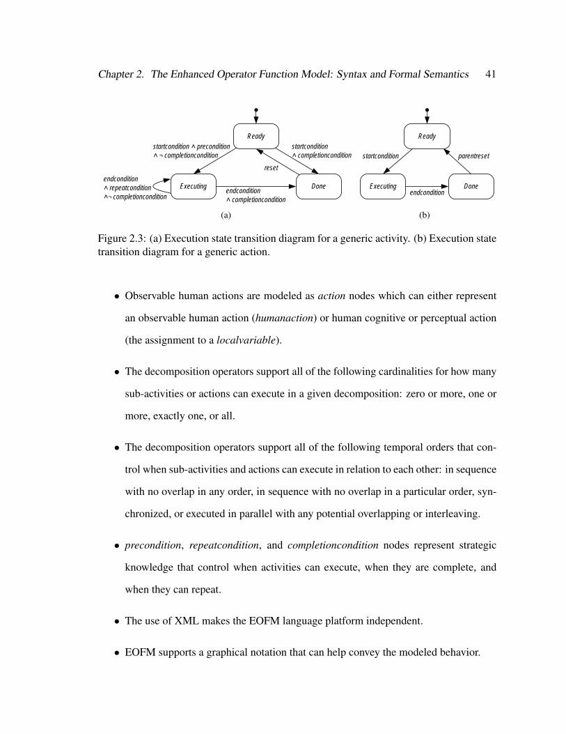
Chapter 2. The Enhanced Operator Function Model: Syntax and Formal Semantics 41
Ready
Executingendcondition ˄ repeatcondition˄¬ completioncondition
startcondition ˄ precondition˄ ¬ completioncondition
endcondition˄ completioncondition
startcondition ˄ completioncondition
Done
reset
(a)
Ready
Executing
startcondition
endconditionDone
parentreset
(b)
Figure 2.3: (a) Execution state transition diagram for a generic activity. (b) Execution statetransition diagram for a generic action.
• Observable human actions are modeled as action nodes which can either represent
an observable human action (humanaction) or human cognitive or perceptual action
(the assignment to a localvariable).
• The decomposition operators support all of the following cardinalities for how many
sub-activities or actions can execute in a given decomposition: zero or more, one or
more, exactly one, or all.
• The decomposition operators support all of the following temporal orders that con-
trol when sub-activities and actions can execute in relation to each other: in sequence
with no overlap in any order, in sequence with no overlap in a particular order, syn-
chronized, or executed in parallel with any potential overlapping or interleaving.
• precondition, repeatcondition, and completioncondition nodes represent strategic
knowledge that control when activities can execute, when they are complete, and
when they can repeat.
• The use of XML makes the EOFM language platform independent.
• EOFM supports a graphical notation that can help convey the modeled behavior.
Chapter 2. The Enhanced Operator Function Model: Syntax and Formal Semantics 42
The EOFM language specifically extends OFM [139, 178] in several ways. Firstly,
EOFM allows the analyst to explicitly define the input-output relationship between the
human task behavior and the system: defining inputs (input variables), outputs (human ac-
tions with specified behavior), and internal state (local variables and task structure). OFM
only explicitly defines the task structure from which the input and output information must
be inferred. Secondly, OFM only supports the equivalent of EOFM’s and_seq, or_seq,
xor, and ord decomposition operators. Thus, EOFM extends OFM by supporting optional
execution (the optor decomposition operators) and parallelism (operators with the _par
suffix and the sync operator). Finally, OFM does not have a formal semantics to explicitly
define how a model instantiated in it is to be interpreted, EOFM does. This is a signif-
icant contribution in that the EOFM’s formal semantics have been used as the basis of a
translator which converts instantiated EOFMs into a model checking language (see [33])
which allows them to be subject to formal verification. This is discussed in greater depth
in Chapter 4.
Because the EOFM language is specified in RELAX NG and implemented in XML, the
language should be easy to parse with existing code libraries. The wide support of these
technologies also means that analysts can make use of a number of existing tools when
working with the EOFM language. For example, we have used existing XML parsing
technology in the creation of both our java-based EOFM to SAL translation process (see
[28] and Chapter 4) and a Microsoft Office-based EOFM renderer (see [30] and Chapter 7).
We have also successfully used the RELAX NG specification with the oXygen xml editor2
which allows EOFM instantiations to be implemented in an environment that supports code
completion, code highlighting, and dynamic syntax checking.
2http://www.oxygenxml.com/

Chapter 2. The Enhanced Operator Function Model: Syntax and Formal Semantics 43
2.3.1 Language Extensions
The EOFM language has been used successfully in a number of human-automation inter-
action analyses (see [26],[31],[29] and latter chapters). However, there are ways it could
be improved.
One feature that is supported by UAN [98] and CTT [155] is the ability for activities
to be interrupted when a higher priority activity becomes relevant due to a change in the
human-device interface or environmental conditions. For example, an automobile driver
may need to respond to traffic that has cut him off even in the midst of responding to a
light further down the road. After the higher priority activity has been addressed, UAN
and CTT support means of restarting, resuming, or abandoning any interrupted activities.
Future work should investigate how such feature can be incorporated into the EOFM.
The current implementation of the EOFM does not enforce a specific syntax for type
constructions, initial values, and condition Boolean expressions nor does it specify a stan-
dard set of basic types for defining its variables. These must conform to the syntax sup-
ported by the infrastructure the model is integrating with. Relax NG offers a variety of
ways in which standards for these modeling concepts could be enforced such as additional
XML structures and regular expressions for data formatting. Future work should investi-
gate how these might be used to further specify EOFM syntax.
The current EOFM implementation assumes that all root activities are temporally re-
lated with the equivalent of a optor_seq decomposition operator. Future work should de-
termine if this is descriptive enough, or if more options are necessary.
Although the EOFM has been designed to support multiple operators, to date it has
only been used to model single operator systems [25–28, 31, 34]. There are a number of
systems that depend on multiple human operators interacting with automation.
The current EOFM language supports the ability for multiple humanoperator nodes to
Chapter 2. The Enhanced Operator Function Model: Syntax and Formal Semantics 44
share input information via inputvariablelink nodes. While this accomplishes the desired
goal, it requires that all inputs be defined within a given humanoperator node. This results
in a strong coupling between humanoperator nodes and associates the input exclusively
with a human operator rather than the source of that input like the environment or a human-
device interface. Similarly, multiple human operators may be able to interact with a human-
device interface that they share, allowing each to submit identical human actions to system
automation. The current implementation of the EOFM language supports this, but requires
that these human actions be defined using different names in the associated humanoperator
nodes. Thus it is the job of the modeler to ensure that these human actions are treated
the same when the language is interpreted. Finally, multi-human operator systems may
support direct communication between human operators that does not occur through a
human-device interface. The current implementation of the EOFM does not support this
feature.
These limitations could be resolved by modifying the EOFM semantics so that in-
putvariable and humanaction nodes as well as communication channels between human
operators could be defined independently of the humanoperator nodes, and referenced
where appropriate in these nodes. Future work will investigate how these features might
be incorporated into EOFM.
Another limitation comes in the way task structures (activity and action hierarchies) can
be reused between humanoperator nodes. In the current implementation, activities must be
defined in one humanoperator node and referenced in others using activitylink nodes. This
too results in strong coupling and does not support good objected-oriented design. Their
are a variety of different architectures that might be supported in a multi-operator system:
there may be multiple operators with a mixture of shared and discrepant task structures,
and there may be shared or discrepant human-device interfaces. Object-orient concepts
such as inheritance, interfaces, and polymorphism may allow these types of relationships
Chapter 2. The Enhanced Operator Function Model: Syntax and Formal Semantics 45
to be more easily and flexibly instantiated in EOFM. Future work should investigate how
this might be accomplished.
Chapter 3
Human-automation Interaction Formal
Modeling Architectural Framework∗
Chapter 1 showed that a significant amount of work has been done in the interaction
of human-automation interaction and formal methods. While this has produced use-
ful results, the models have not included all of the components necessary to analyze
human-automation interaction. For human factors engineering (HFE) analyses of human-
automation interaction, the minimal set of components are the goals and procedures of the
human operator; the automated system and its human interface; and the constraints im-
posed by the operational environment. Cognitive work analysis is concerned with identi-
fying constraints in the operational environment that shape the mission goals of the human
operator [179]; cognitive task analysis is concerned with describing how human operators
normatively and descriptively perform goal oriented tasks when interacting with an auto-
mated system [124, 167]; and modeling frameworks such as [69] seek to find discrepancies
between human mental models, human-device interfaces, and device automation. In this
context, problems related to human-automation interaction may be influenced by the hu-
man operator’s mission, the human operator’s task behavior, the operational environment,
∗This chapter is derived from [31]
46
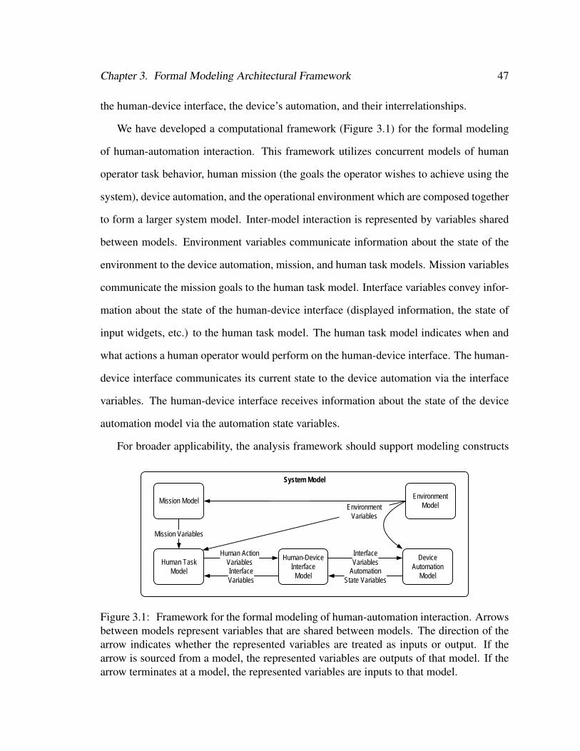
Chapter 3. Formal Modeling Architectural Framework 47
the human-device interface, the device’s automation, and their interrelationships.
We have developed a computational framework (Figure 3.1) for the formal modeling
of human-automation interaction. This framework utilizes concurrent models of human
operator task behavior, human mission (the goals the operator wishes to achieve using the
system), device automation, and the operational environment which are composed together
to form a larger system model. Inter-model interaction is represented by variables shared
between models. Environment variables communicate information about the state of the
environment to the device automation, mission, and human task models. Mission variables
communicate the mission goals to the human task model. Interface variables convey infor-
mation about the state of the human-device interface (displayed information, the state of
input widgets, etc.) to the human task model. The human task model indicates when and
what actions a human operator would perform on the human-device interface. The human-
device interface communicates its current state to the device automation via the interface
variables. The human-device interface receives information about the state of the device
automation model via the automation state variables.
For broader applicability, the analysis framework should support modeling constructs
System Model
Human Task Model
DeviceAutomation
Model
Human-Device Interface
Model
Mission ModelEnvironment
Model
Mission Variables
Human ActionVariablesInterfaceVariables
InterfaceVariables
AutomationState Variables
EnvironmentVariables
Figure 3.1: Framework for the formal modeling of human-automation interaction. Arrowsbetween models represent variables that are shared between models. The direction of thearrow indicates whether the represented variables are treated as inputs or output. If thearrow is sourced from a model, the represented variables are outputs of that model. If thearrow terminates at a model, the represented variables are inputs to that model.
Chapter 3. Formal Modeling Architectural Framework 48
useful to the human factors engineer in order to allow him to effectively model human
missions, human tasks, and human-device interfaces. Because an engineer may wish to
rerun verifications using different missions, task models, human-device interfaces, envi-
ronments, or automation behaviors, these components should remain decoupled (as is the
case in Figure 3.1). Finally, the modeling technique must be capable of representing the
target systems with enough fidelity to allow the engineer to perform the desired verifica-
tion, and do so in a reasonable amount of time (this could mean several hours for a small
project, or several days for a more complicated one).
This chapter describes an instantiation of this framework using a model of a Baxter
Ipump Pain Management System [20], a patient controlled analgesia (PCA) pump that
administers pain medication in accordance with constraints defined by a health care tech-
nician (described in section 3.1.1). Models were developed in two phases. The first phase
involved the construction and debugging of the human-device interface, device automa-
tion, and human mission models (an environmental model was not included because of
the general stability of the environment in which an actual pump operates) with an uncon-
strained human task model serving as a placeholder for a more realistic human task model.
The protocol necessary for coordinating behavior between the human task behavior and the
other system elements was also developed in this phase. The second extended the model
produced in Phase 1 with a realistic model of the human task, completing the framework.
Even though the target device in this modeling effort was seemingly simple, the system
model that was initially developed in Phase 1 (Phase 1a) was too difficult for the model
checker to process quickly and too complex for it to verify. Thus a number of revisions
were undertaken [27]. In Phase 1b a reduced and abstracted model of the Baxter Ipump was
produced which, while capable of being used in some verifications, did so at the expense of
limiting the number of goals represented in the human mission model. This Phase 1b model
limited the usefulness of incorporating human task behavior in Phase 2. Thus, in Phase
Chapter 3. Formal Modeling Architectural Framework 49
1c, the system model was reduced to encompass the programming procedure for a much
simpler PCA pump. In Phase 2, the incorporation of the more realistic human task behavior
actually resulted in a reduction of the total system model’s complexity, but did so at the
expense of an increase in verification time. This chapter discusses these modeling phases,
the verification results produced in them, and their associated compromises in relation to
the goals of the modeling architecture.
3.1 Methods
3.1.1 The Target System
The Baxter Ipump is an automated machine that controls delivery of sedative, analgesic,
and anesthetic medication solutions [20]. Solution delivery via intravenous, subcutaneous,
and epidural routes is supported. Medication solutions are typically stored in bags locked
in a compartment on the back of the pump.
Pump behavior is dictated by internal automation, which can depend on how the pump
is programmed by a human operator. Pump programming is accomplished via its human-
device interface (Figure 3.2) which contains a dynamic LCD display, a security key lock,
and eight buttons. When programming the pump, the operator is able to specify all of
the following: whether to use periodic or continuous doses of medications (i.e. the mode
which can be PCA, Basal + PCA, or Continuous), whether to use prescription information
previously programmed into the pump, the fluid volume contained in the medication bag,
the units of measure used for dosage (ml, mg, or µg), whether or not to administer a
bolus (an initial dose of medication), dosage amounts, dosage flow rates (for either basal
or continuous rates as determined by the mode), the delay time between dosages, and one
hour limits on the amount of delivered medication.

Chapter 3. Formal Modeling Architectural Framework 50
Start Stop
Enter On/Off
ClearC
0000 ml SetFluid Volume
LCD Display Interface Message
Displayed ValueCursor
Security Key
LeftButton
Up (Scroll)Button
RightButton
ClearButton
Start Button
Stop Button
Enter Button
On/OffButton
l
>
Figure 3.2: A simplified representation of the Baxter Ipump’s human-device interface.Note that the actual pump contains additional controls and information conveyances.
During programming, the security key is used to lock and unlock the compartment
containing the medication solution. The unlocking and locking process is also used as a
security measure to ensure that an authorized person is programming the pump. The start
and stop buttons are used to start and stop the delivery of medication at specific times
during programming. The on-off button is used to turn the device on and off.
The LCD display supports pump operation options. When the operator chooses be-
tween two or more options, the interface message indicates what is being chosen, and the
initial or default option is displayed. Pressing the up button allows the practitioner to scroll
through the available options.
When a numerical value is required, the interface message conveys its name and the
displayed value is presented with the cursor under one of the value’s digits. The practitioner
can move the position of the cursor by pressing the left and right buttons. He or she
can press the up button to scroll through the different digit values available at that cursor
position. The clear button sets the displayed value to zero. The enter button is used to
confirm values and treatment options.
Aside from the administration of treatment, the pump’s automation supports dynamic
Chapter 3. Formal Modeling Architectural Framework 51
checking and restriction of operator entered values. Thus, in addition to having hard limits
on value ranges, the extrema can change dynamically in response to other user specified
values.
3.1.2 Apparatus
All formal models were constructed using the Symbolic Analysis Laboratory (SAL) lan-
guage [65] because of its associated analysis and debugging tools, and its support for both
the asynchronous and synchronous composition of different models (modules using SAL’s
internal semantics). The task model representations described next were translated into the
SAL language as a single module using a custom-built java program [33]. All verifications
were done using SAL-SMC 3.0, the SAL symbolic model checker1. Verifications were
conducted on a 3.0 gigahertz dual-core Intel Xeon processor with 16 gigabytes of RAM
running the Ubuntu 9.04 desktop.
Human task models were created using EOFM [28, 33] (see Chapter 2).
3.1.3 Verification Specification
Two specifications were employed in each of the modeling phases: both were written
in linear temporal logic and evaluated using SAL-SMC. The first (3.1), used for model
1Some model debugging was also conducted using SAL’s bounded model checker. See Chapter 4 for amore in depth discussion of SAL.
Chapter 3. Formal Modeling Architectural Framework 52
debugging, verifies that a valid prescription could be programmed into the pump:
G¬
iInterfacemessage = TreatmentAdministering
∧Mode = PrescribedMode
∧ FluidVolume = PrescribedFluidVolume
∧ PCADose = PrescribedPCADose
∧ Delay = PrescribedDelay
∧ BasalRate = PrescribedBasalRate
∧ 1HourLimit = Prescribed1HourLimit
∧ Bolus = PrescribedBolus
∧ ContinuousRate = PrescribedContinuousRate
(3.1)
Here, if the model is able to enter a state indicating that treatment is administering (In-
terfaceMessage = TreatmentAdministering) with the entered (or programmed) prescription
values (Mode, FluidVolume, ..., ContinuousRate) matching the prescription values gener-
ated by the mission model (variables with the Prescrived prefix), a counterexample would
be produced illustrating how that prescription was programmed.
The second specification (3.2) represented a safety property that was expected to verify
to true, thus allowing the model checker to traverse the entire state space of each phase’s
model. Because such a verification allows SAL to report the size of a model’s state space,
verifications using this specification would provide some means of comparing the com-
plexity of the models produced in each phase.
G¬
InterfaceMessage = TreatmentAdministering
∧Mode 6= Continuous
∧ Delay = 0
(3.2)
Here, the specification is asserting that the model should never enter a state where
Chapter 3. Formal Modeling Architectural Framework 53
treatment is administering in the PCA or Basal + PCA modes (Mode 6= Continuous) when
there is no delay between doses2. Thus, if 3.2 verifies to true, the pump will never allow
a practitioner to enter prescriptions that would allow patients to continuously administer
PCA doses to themselves [20].
3.2 Phase 1a: A Representative Model of the Ipump
3.2.1 Model Description
An initial model was created to conform to the architectural and design philosophy repre-
sented in Figure 3.2: the mission was represented as a set of viable prescriptions options;
the mission, human operator, human-device interface, and device automation were mod-
eled independently of each other; and the behavior of the automated system and human-
device interface models was designed to accurately reflect the behavior of these systems as
described in the user’s manual [20] and observed through direct interaction with the device.
An unconstrained human operator was constructed that could issue any valid human action
to the human-device interface model at any given time. Because the PCA pump gener-
ally operates in a controlled environment, away from temperature and humidity conditions
that might affect the performance of the pump’s automation, no environmental model was
included. Finally, because documentation related to the internal workings of the pump
was limited, the system automation model was restricted to that associated with the pump
programming procedure: behavior that could be gleaned from the operator’s manual [20],
correspondences with hospital staff, and direct interaction with the pump.
2A delay can only been set when the PCA or Basal + PCA modes have been selected by the humanoperator. There are no delays between doses when the pump is in the Continuous mode.

Chapter 3. Formal Modeling Architectural Framework 54
3.2.2 Model Coordination
Model infrastructure was required to ensure that human operator actions were properly
recognized by the human-device interface model. In an ideal modeling environment,
human action behavior originating from the human operator model could have both an
asynchronous and synchronous relationship with the human-device interface model. Syn-
chronous behavior would allow the human-device interface model to react to user actions
in the same transition in which they were issued/performed by the human operator model.
However, both the human operator and human-device interface models operate indepen-
dently of each other, and may have state transitions that are dependent on internal or exter-
nal conditions that are not directly related to the state of the other model. This suggests an
asynchronous relationship. SAL only allows models to be composed with each other asyn-
chronously or synchronously (but not both). Thus, it was necessary to adapt the models to
support features associated with the unused composition.
Asynchronous composition was used to compose the human operator and human-
device interface models. This necessitated some additional infrastructure to prevent the
human operator model from issuing user inputs before the human-device interface model
was ready to interpret them and to prevent the human operator model from terminating a
given input before the interface could respond to it. This was accomplished through the
addition of two Boolean variables: one indicating that input had been submitted (hence-
forth called Submitted) and a variable indicating the interface was ready to receive actions
(henceforth called Ready). This coordination occurred as follows:
• If Ready is true and Submitted is false, the human operator module sets one or more
of the human action variables to a new input value and sets Submitted to true.
• If Ready and Submitted are true, the human-device interface module responds to the
values of the human action variables and sets Ready to false.
Chapter 3. Formal Modeling Architectural Framework 55
• If Ready is not true and Submitted is true, the human operator module sets Submitted
to false.
• If Ready and Submitted are both false and the automated system is ready for addi-
tional human operator input, the human-device interface module sets Ready to true.
3.2.3 Verification Results
Attempts to verify this model using the specifications in 3.1 and 3.2 resulted in two prob-
lems related to the feasibility and usefulness of the verification procedure. Firstly, the
SAL-SMC procedure for translating the SAL code into a binary decision diagram (BDD)
took more than 24 hours, a time frame impractical for debugging such a limited model.
Secondly, the verification process which followed the construction of the BDD eventually
ran out of memory, thus not returning a verification result.
3.3 Phase 1b: A Reduced Baxter Ipump Model
As a result of the failed verification of the model produced in Phase 1a, significant revisions
were required to make the model more tractable. These are discussed below.
3.3.1 Representation of Numerical Values
In order to reduce the time needed to convert the SAL-code model to a BDD, a number of
modifications were made to the model from Phase 1a by representing model constructs in
ways more readily processed by the model checker. As such, the modifications discussed
here did not ultimately make the BDD representation of the model smaller, but merely
expedited its construction.
Chapter 3. Formal Modeling Architectural Framework 56
3.3.1.1 Redundant Representation of Values
Two different representations of the values programmed into the pump by the operator
were used in the human-device interface and device automation models. Because the
human-device interface required the human operator to enter values by scrolling through
the available values for individual digits, an array of integer digits was appropriate for the
human-device interface model. However, because the system automation was concerned
with dynamically checking limits and using entered values to compute other values, a nu-
merical representation of the actual value was more convenient for the automated system
model.
This redundancy burdened the BDD translator. This was remedied by eliminating the
digit array representations and using functions to enable actions from the human task model
to incrementally change individual digits within a value.
3.3.1.2 Real Numbers and Integers
In the model produced in Phase 1a, all numerical values were represented as real values
with restricted ranges. This was done because most user specified values were either in-
tegers or floating point numbers (precise to a single decimal point). No data abstractions
were initially considered because the nature of the human task (modeled in Phase 2) re-
quired manipulation of values’ individual digits. However, representing values this way
proved especially challenging for the BDD translator. Thus, all values were modified so
that they could be represented as restricted range integers. For integer variables repre-
senting floating point numbers, this meant that the model value was ten times the value it
represented. This representation allowed the values to still be manipulated at the individual
digit level, while making them more readily interpretable by the BDD translator.
Chapter 3. Formal Modeling Architectural Framework 57
3.3.1.3 Variable Ranges
In the Phase 1a model, the upper bound on the range of all value-based variables was set to
the theoretical maximum of any value that could be programmed into the pump: 999993.
However, in order to reduce the amount of work required for the BDD conversion, the range
of each numerically valued variable was given a specific upper bound that corresponded to
the maximum value it could actually assume in the device.
3.3.2 Model Reduction
In order to reduce the size of the model, a variety of elements were removed. In all cases
these reductions were meant to reduce the number of state variables in the human-device
interface or Device Automation models (slicing), or reduce the range of values a variable
could assume (data abstraction). Unfortunately, each of these reductions also affected what
human tasks could ultimately be modeled and thus verified in subsequent model iterations.
All of the following reductions were undertaken:
• In the Phase 1a model, the mission model could generate a prescription from the
entire available range of valid prescriptions. This was changed so that fewer pre-
scription options were generated in Phase 1b’s mission model: that of programming
a prescription with a continuous dosage with two options for bolus delivery (0.0
and 1.0 ml) and two continuous flow rate options (1.0 and 9.0 ml/hr). While this
significantly reduced the number of model states, it also reduced the number of pre-
scriptions that could be used in verification procedures.
• In the Phase 1a model, the human-device interface model would allow the operator
to select what units to use when entering prescriptions (ml, mg, or µg). Only the
3All lower bounds were set to 0.
Chapter 3. Formal Modeling Architectural Framework 58
ml unit option was included in the Phase 1b model. This reduced the number of
interface messages in the model, allowed for the removal of several variables (those
related to the unit option selection, and solution concentration specification), and
reduced the ranges required for several numerical values related to the prescription.
This eliminated the option of including unit selection and concentration specification
task behaviors in the model.
• In the Phase 1a model, both the human-device interface and device automation mod-
els encompassed behavior related to the delivery of medication solution during the
priming and bolus administration procedures. During priming, the human-device in-
terface allows the operator to repeatedly instruct the pump to prime until all air has
been pushed out of the connected tubing. During bolus administration, the human-
device interface allows the operator to terminate bolus infusion by pressing the stop
button twice. This functionality was removed from the Phase 1b models, thus elimi-
nating interface message states and numerical values indicating how much fluid had
been delivered in both procedures. This eliminated the possibility of incorporating
task behavior related to pump priming and bolus administration in the model.
• The Phase 1a model mimicked the security features found in the original device
which required the human operator to unlock and lock the device on startup and en-
ter a security code. This functionality was removed from the Phase 1b model which
reduced the number of interface messages in the model and removed the numeri-
cal variable (with a 0-999 range) associated with entering the security code. This
eliminated the possibility of modeling human task behavior related to unlocking and
locking the pump as well as entering the security code in the model.
• In the Phase 1a model, the interface message could automatically transition to being
blank: mimicking the actual pump’s ability to blank its screen after three seconds
Chapter 3. Formal Modeling Architectural Framework 59
of operator inactivity. Because further operator inaction would result in the original
device issuing a “left in programming mode” alert, a blank interface message could
automatically transition to an alert issuance. This functionality was removed from
the Phase 1b model, eliminating several interface messages as well as variables that
kept track of the previous interface message. Thus, the option of modeling operator
task response to screen blanking and alerts was removed from the model.
While these reductions resulted in the Phase 1b model being much smaller and more man-
ageable than the original, the ability to model some of the task behaviors originally asso-
ciated with the device had to be sacrificed.
3.3.3 Results
The Phase 1b model was able to complete the verification procedure with 3.1 and produce
a counterexample with a search depth of 54 in approximately 5.9 hours, with the majority
of that time (5.4 hours) used for creating the BDD representation [27]. Not surprisingly,
the model checker ran out of memory when attempting to verify 3.2.
3.4 Phase 1c: A Simpler PCA Pump Model
While the model developed in Phase 1b did produce usable results and has subsequently
been used in the verification of additional properties (see [26]), this power came at the
expense of a reduction in the scope of the mission model. Since the mission directly influ-
ences what human behavior will execute, this limited the human task behavior that could
ultimately be verified as part of the system model. Further, the fact that the Phase 1b model
was too complex for 3.2 to be verified potentially limited any future model development
that might add complexity. To remedy these shortcoming, the model produced in Phase
Chapter 3. Formal Modeling Architectural Framework 60
1b was further reduced to one that encompassed the programming of the most basic PCA
pump functionality while the ranges of possible values for the remaining mission model
variables were expanded to be more realistic.
3.4.1 Model Reduction
To obtain a smaller PCA model, all of the following were removed: the selection of mode
and the ability to specify a basal rate, continuous rate, bolus dosage, and fluid volume. As
a result, associated interface messages and variables were removed along with the ability
to model their programming as part of the human task behavior model. This resulted in
a model that only encompassed functionality for programming a PCA dose, programming
the delay between PCA doses, turning the pump on and off, and starting and stopping
the administration of treatment: functionality compatible with the most basic PCA pump
operations (see [9]).
Value ranges were further restricted to reduce the size of the model. Specifically, the
upper bound on the acceptable delay between PCA dosages was changed from 240 to 60
minutes. This, coupled with the other reductions, had the added benefit of allowing the
number of digits required for the programming of pump values to be reduced to 2 rather
than the original 4.
The reductions in other areas allowed the scope of the delays and PCA dosages gener-
ated by the mission model to be expanded to a more representative set. For PCA dosages,
the full range of values from 0.1 to 9.9 in 0.1 ml increments were supported. For delay
between dosages, five options were available: delays of 10, 15, 30, 45, and 60 minutes.
All pump interface functionality was retained from the previous models. Thus, the
unconstrained human task model was unchanged as was the human task and human-device
interface models’ communication protocol.
Chapter 3. Formal Modeling Architectural Framework 61
3.4.2 Results
The Phase 1c model ran the verification procedure for 3.1 (with the eliminated variables
removed) in 6 seconds with a search depth of 22, much faster than the model from Phase
1b. The verification of the specification in 3.2 verified to true in 129 seconds with a search
depth of 259 and 78,768,682,750 visited states.
3.5 Phase 2: Incorporating Models of Human Behavior
In the second phase of modeling, we expanded our instantiation of the framework by in-
corporating a more realistic human task behavior model. We therefore replaced the uncon-
strained human operator in the Phase 1c model with a human task behavior model derived
from pump documentation [20] and training materials. This model utilized the EOFM
concepts and thus required some additional infrastructure in order to incorporate it into the
formal system model. We describe the behaviors that were modeled and report verification
results for the produced system model.
3.5.1 Human Task Behavior Modeling and Translation
The pump’s materials contained six high-level goal directed behaviors for performing a
variety of pump activities relevant to the Phase 1c model:
• Turning on the pump,
• Stopping the infusion of medication,
• Turning off the pump,
• Entering a prescribed value for PCA dosage volumes (in ml)
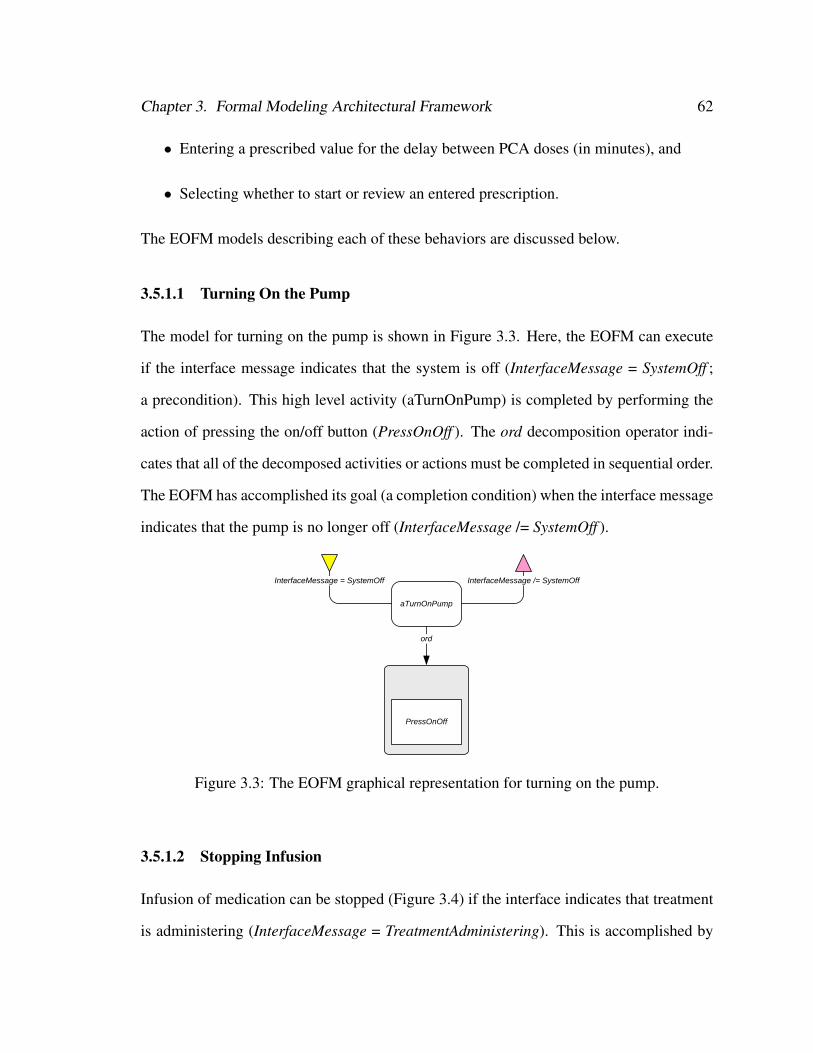
Chapter 3. Formal Modeling Architectural Framework 62
• Entering a prescribed value for the delay between PCA doses (in minutes), and
• Selecting whether to start or review an entered prescription.
The EOFM models describing each of these behaviors are discussed below.
3.5.1.1 Turning On the Pump
The model for turning on the pump is shown in Figure 3.3. Here, the EOFM can execute
if the interface message indicates that the system is off (InterfaceMessage = SystemOff ;
a precondition). This high level activity (aTurnOnPump) is completed by performing the
action of pressing the on/off button (PressOnOff ). The ord decomposition operator indi-
cates that all of the decomposed activities or actions must be completed in sequential order.
The EOFM has accomplished its goal (a completion condition) when the interface message
indicates that the pump is no longer off (InterfaceMessage /= SystemOff ).
aTurnOnPump
InterfaceMessage = SystemOff InterfaceMessage /= SystemOff
ord
PressOnOff
Figure 3.3: The EOFM graphical representation for turning on the pump.
3.5.1.2 Stopping Infusion
Infusion of medication can be stopped (Figure 3.4) if the interface indicates that treatment
is administering (InterfaceMessage = TreatmentAdministering). This is accomplished by
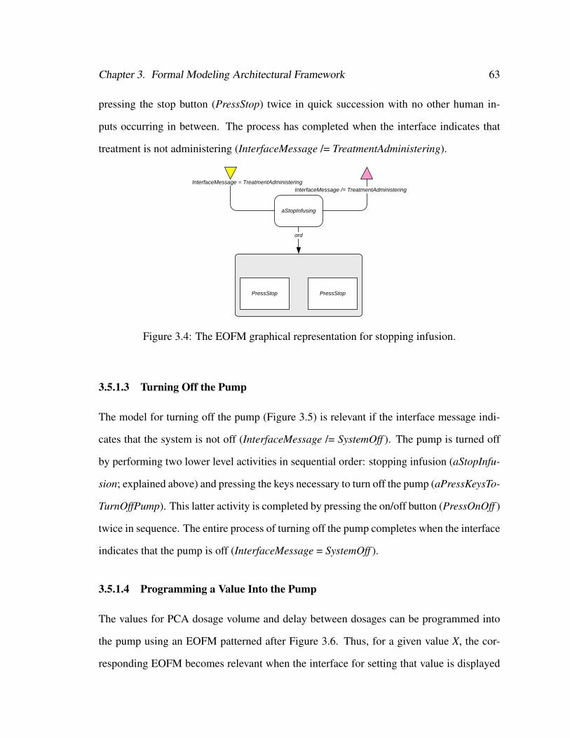
Chapter 3. Formal Modeling Architectural Framework 63
pressing the stop button (PressStop) twice in quick succession with no other human in-
puts occurring in between. The process has completed when the interface indicates that
treatment is not administering (InterfaceMessage /= TreatmentAdministering).
aStopInfusing
InterfaceMessage = TreatmentAdministeringInterfaceMessage /= TreatmentAdministering
ord
PressStop PressStop
Figure 3.4: The EOFM graphical representation for stopping infusion.
3.5.1.3 Turning Off the Pump
The model for turning off the pump (Figure 3.5) is relevant if the interface message indi-
cates that the system is not off (InterfaceMessage /= SystemOff ). The pump is turned off
by performing two lower level activities in sequential order: stopping infusion (aStopInfu-
sion; explained above) and pressing the keys necessary to turn off the pump (aPressKeysTo-
TurnOffPump). This latter activity is completed by pressing the on/off button (PressOnOff )
twice in sequence. The entire process of turning off the pump completes when the interface
indicates that the pump is off (InterfaceMessage = SystemOff ).
3.5.1.4 Programming a Value Into the Pump
The values for PCA dosage volume and delay between dosages can be programmed into
the pump using an EOFM patterned after Figure 3.6. Thus, for a given value X, the cor-
responding EOFM becomes relevant when the interface for setting that value is displayed
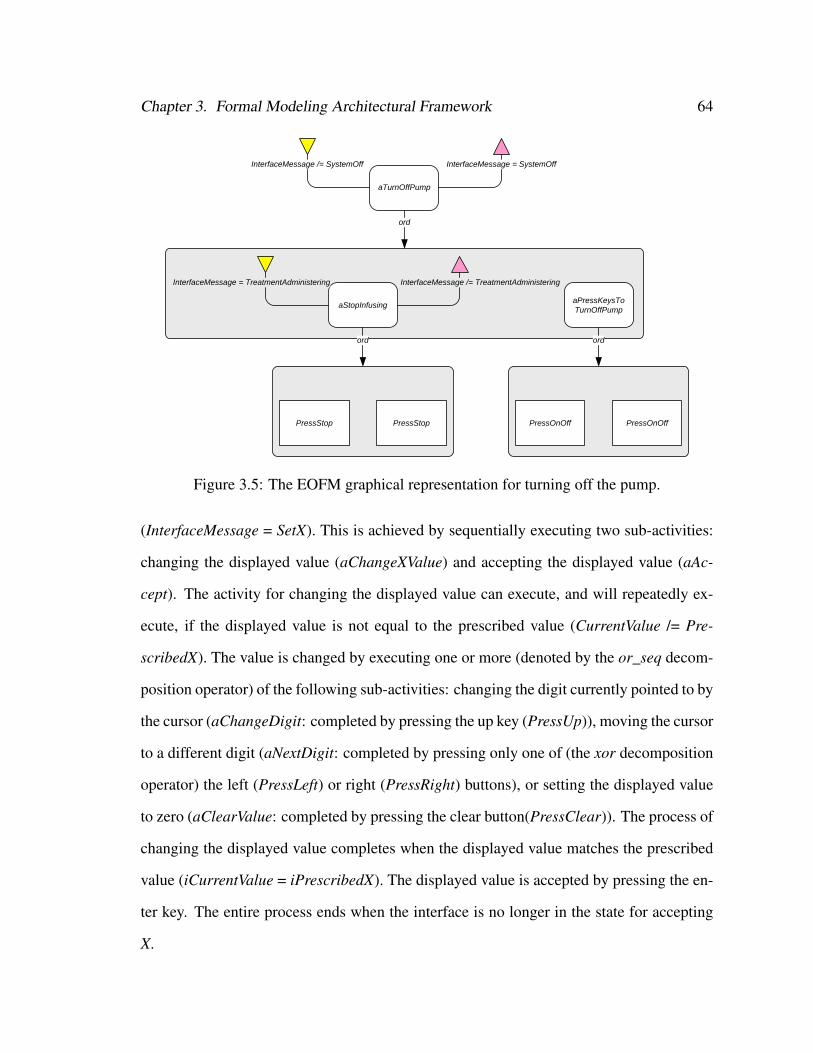
Chapter 3. Formal Modeling Architectural Framework 64
aTurnOffPump
InterfaceMessage /= SystemOff InterfaceMessage = SystemOff
ord
aStopInfusing
InterfaceMessage = TreatmentAdministering InterfaceMessage /= TreatmentAdministering
ord
PressStop PressStop
aPressKeysToTurnOffPump
ord
PressOnOff PressOnOff
Figure 3.5: The EOFM graphical representation for turning off the pump.
(InterfaceMessage = SetX). This is achieved by sequentially executing two sub-activities:
changing the displayed value (aChangeXValue) and accepting the displayed value (aAc-
cept). The activity for changing the displayed value can execute, and will repeatedly ex-
ecute, if the displayed value is not equal to the prescribed value (CurrentValue /= Pre-
scribedX). The value is changed by executing one or more (denoted by the or_seq decom-
position operator) of the following sub-activities: changing the digit currently pointed to by
the cursor (aChangeDigit: completed by pressing the up key (PressUp)), moving the cursor
to a different digit (aNextDigit: completed by pressing only one of (the xor decomposition
operator) the left (PressLeft) or right (PressRight) buttons), or setting the displayed value
to zero (aClearValue: completed by pressing the clear button(PressClear)). The process of
changing the displayed value completes when the displayed value matches the prescribed
value (iCurrentValue = iPrescribedX). The displayed value is accepted by pressing the en-
ter key. The entire process ends when the interface is no longer in the state for accepting
X.
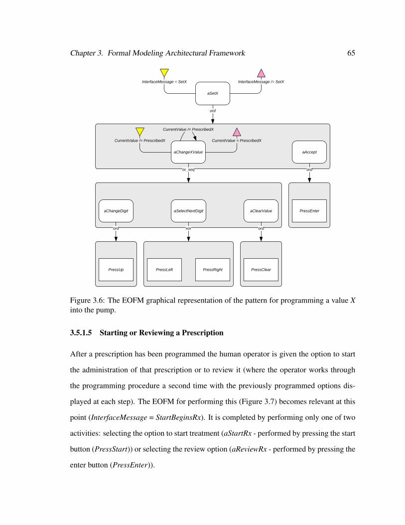
Chapter 3. Formal Modeling Architectural Framework 65
aSetX
InterfaceMessage = SetX InterfaceMessage /= SetX
ord
aChangeXValue
CurrentValue /= PrescribedX
CurrentValue /= PrescribedX
CurrentValue = PrescribedX
or_seq
aChangeDigit
ord
PressUp
aSelectNextDigit
xor
PressLeft PressRight
aClearValue
ord
PressClear
aAccept
ord
PressEnter
Figure 3.6: The EOFM graphical representation of the pattern for programming a value Xinto the pump.
3.5.1.5 Starting or Reviewing a Prescription
After a prescription has been programmed the human operator is given the option to start
the administration of that prescription or to review it (where the operator works through
the programming procedure a second time with the previously programmed options dis-
played at each step). The EOFM for performing this (Figure 3.7) becomes relevant at this
point (InterfaceMessage = StartBeginsRx). It is completed by performing only one of two
activities: selecting the option to start treatment (aStartRx - performed by pressing the start
button (PressStart)) or selecting the review option (aReviewRx - performed by pressing the
enter button (PressEnter)).
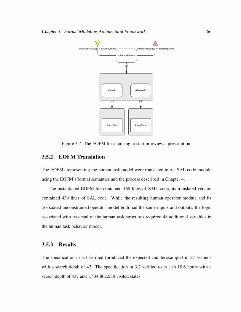
Chapter 3. Formal Modeling Architectural Framework 66
aStartOrReview
InterfaceMessage = StartBeginsRx InterfaceMessage /= StartBeginsRx
xor
aStartRx
ord
PressStart
aReviewRx
ord
PressEnter
Figure 3.7: The EOFM for choosing to start or review a prescription.
3.5.2 EOFM Translation
The EOFMs representing the human task model were translated into a SAL code module
using the EOFM’s formal semantics and the process described in Chapter 4.
The instantiated EOFM file contained 168 lines of XML code, its translated version
contained 439 lines of SAL code. While the resulting human operator module and its
associated unconstrained operator model both had the same inputs and outputs, the logic
associated with traversal of the human task structures required 48 additional variables in
the human task behavior model.
3.5.3 Results
The specification in 3.1 verified (produced the expected counterexample) in 57 seconds
with a search depth of 42. The specification in 3.2 verified to true in 10.6 hours with a
search depth of 437 and 1,534,862,538 visited states.
Chapter 3. Formal Modeling Architectural Framework 67
3.6 Discussion
This work has shown that it is possible for human-automation interaction to be evaluated
using the architecture in Figure 3.1. However, this came as a result of tradeoffs between
the goals the architecture is designed to support:
1. Model constructs need to be represented in a useful form for human factors engineers
who will be building and evaluating many of the models;
2. The sub-models should be decoupled and modular (as in Figure 3.1) in order to allow
for interchangeability of alternative sub-models; and
3. The constructed models need to be capable of being verified in a reasonable amount
of time.
We discuss how each of these goals was impacted and how related issues might be ad-
dressed.
3.6.1 Goals 1: Model Representation Usefulness
Many of the model revisions were associated with representing model constructs in ways
that were more readily interpretable by the model checker rather than the human factors
engineer. These primarily took the form of converting floating point and digit array values
into integers in Phase 1b. Further, the extensive model reductions that were undertaken in
Phase 1c would be very cumbersome for a human factors engineer.
There are two potential ways to address this issue. One solution would be to improve
the model checkers themselves. Given that the modifications would not actually change
the number of reachable states in the system, this would suggest that the model checker
need only optimize the BDD conversion algorithms.
Chapter 3. Formal Modeling Architectural Framework 68
Alternatively, additional modeling tools could be used to help mitigate the situation.
Such tools could allow human factors engineers to construct or import human-device in-
terface prototypes, and translate them into model checker code. This would allow the
representations necessary for ensuring a model’s efficient processing by the model checker
to be removed from the modeler’s view.
3.6.2 Goal 2: Decoupling of Architecture Sub-models
Because the protocol used to coordinate human actions between the human-device inter-
face and human task models (discussed for Phase 1a and used in all models produced in
all subsequent phases) assumes a particular relationship between variables shared by these
models, they are tightly coupled. Unless a model checker can be made to support both
asynchronous and synchronous relationships between models more elegantly, this coordi-
nation infrastructure cannot be eliminated.
However, a solution may be found in an additional level of abstraction. A toolset for
translating a human-device interface prototype into model checking code, could handle
the construction of the coordination protocol, making this process effectively invisible to
the modeler. Such a process could also allow for more efficient means of coordinating
the human-device interface and human task models: one that might not require the use of
separate models in the actual model checker code.
While the extensive model reductions from Phase 1 greatly diminished the fidelity with
which the model represented the actual PCA pump, this provides some advantages. Since
the model from Phase 2 does not suffer from the memory usage problems encountered in
Phase 1, this opens the door to the addition of other model constructs to be added allowing
for a more complete system analysis.

Chapter 3. Formal Modeling Architectural Framework 69
3.6.3 Goal 3: Model Verifiability
We are predominantly concerned with exploring how formal methods can be used to pro-
vide insights into human factors and systems engineering concerns. If our goal were to
formally verify properties of the Baxter Ipump, the modeling compromises we made in
order to obtain a verifiable model might necessitate a change in modeling philosophy or
verification approach.
There are many barriers to the verifiability of models of realistic systems. These in-
clude large numbers of parallel processes, large ranges of discrete valued variables, and
non-discretely valued variables. The modeling efforts described here were so challenging
because the target system was dependent on a large number of user specified numerical val-
ues, all of which had very large acceptable ranges. This resulted in the scope of the model
being reduced to the point where it could no longer be used for verifying all of the original
human operator task behaviors: with the model produced in Phase 1b making minor com-
promises and the model produced in Phase 1c only allowing for behaviors associated with
basic PCA pump functionality.
As was demonstrated in Phase 2, the verifiability of the model actually increased with
the inclusion of the human task behavior as indicated by the 98% reduction in the reported
state space from the Phase 1c to the Phase 2 model. However, this came at the expense
of the verification process taking 284 times as long. Thus, in a context where verification
time is less important than the size of the model’s state space, the inclusion of the human
task behavior model may generally prove to be advantageous in the formal verification of
systems that have a human-automation interaction component, irrespective of whether the
human behavior is of concern in the verification process. Future efforts should investigate
the different factors that affect this tradeoff.
Even exploiting this advantage, the relative simplicity of the device that was modeled
Chapter 3. Formal Modeling Architectural Framework 70
in this work makes it clear that there are many systems that depend of human-automation
interaction that would be even more challenging to verify, if not impossible, using these
techniques. While the use of bounded model checkers may provide some verification ca-
pabilities for certain systems, there is little that can be done without either using additional
abstraction techniques or future advances in model checking technology and computation
power.
It is common practice in the formal methods community to use more advanced forms
of data abstraction than those employed in this work to mitigate the complexity of variables
with large value ranges (an overview of these methods can be found in [136]). Because
the nature of the modeled human task behavior in this work was concerned with the digit
level editing of the data values, such abstractions were not appropriate for this particu-
lar endeavor. Additionally, automatic predicate abstraction techniques like those used in
counterexample-guided abstraction refinement [55] could potentially alleviate some of the
complexity problems encountered in this work without requiring changes to the models
themselves. Future work should investigate how these different abstraction techniques
could be used when modeling systems that depend on human-automation interaction in
ways that are more useful to human factors engineers.
It is clear that the multiple, large-value-ranged variables were the source of most of
the model complexity problems in the pump example, as shown in the drastic decrease in
verification performance time between the models produced in Phases 1b and 1c. Thus,
had the target system been more concerned with procedural behaviors and less on the
interrelationships between numerical values, the system model would have been much
more tractable. Future work should identify additional properties of systems dependent on
human-automation interaction that lend themselves to being modeled and verified using
the framework discussed here.
Finally, some of the performance issues we encountered can be attributed to our use of
Chapter 3. Formal Modeling Architectural Framework 71
SAL. For example, model checkers such as SPIN [104] do not perform the lengthy process
of constructing the BDD representation before starting the checking process. Future work
should investigate which model checker is best suited for evaluating human-automation
interaction.
3.6.4 Closing Comments
The work presented here has shown that it is possible to construct models of human-
automation interaction as part of a larger system for use in formal verification processes
while adhering to some of the architectural goals in Figure 3.1 4. In making this contribu-
tion, this work has utilized a coordination protocol which allows the human task behavior
to interact with the other elements of the formal system model. It has also shown that
the incorporation of human task behavior models into system models may help alleviate
the state explosion problem in some systems that depend on human-automation interac-
tion given the significant reduction in the size of the models statespace between the formal
system model containing the unconstrained human operator and the one using normative
task behavior defined in an instantiated EOFM. In fact, the use of the two different task
behavior models (both the normative and unconstrained) illustrates the flexibility of the
architectural framework, given that the two were completely interchangeable. Although
the PCA pump application did not include a model of the environment, and no problems
with human-automation interaction were discovered, applications in latter chapters address
both of these issues.
These successes were the result of a number of compromises that produced a model
that was not as representative or modular as desired. Thus, in order for formal methods
to become more useful for the HFE community, the verification technology will need to
4More successful implementations are discussed in subsequent chapters.
Chapter 3. Formal Modeling Architectural Framework 72
be able to support a more diverse set of systems. Further, new modeling tools may be
required to support representations that human factors engineers use. These advances will
ultimately allow formal methods to become a more useful tool for human factors engineers
working with safety critical systems.

Chapter 4
Enhanced Operator Function Model to Symbolic
Analysis Laboratory Translator∗
Chapter 3 showed that task analytic models can be incorporated into a system modeling
framework that also includes models of the human missions, human-device interfaces,
device automation, and the environment. This chapter shows how the formal semantics
of the EOFM (see [33] or Chapter 2) can be used to create a translator that automatically
converts an instantiated EOFM into a formal model that can be formally verified with
SAL’s symbolic model checker. The translation process is verified to produce code that
complies with EOFM’s formal semantics. The complexity of the formal representations of
EOFM task models are benchmarked. We also present an automobile driving case study
illustrating how this process can be used with our method to discover and to analyze a
potential intervention to correct safety properties related to the use of the cruise control.
∗This chapter is derived from [33]
73
Chapter 4. EOFM to SAL Translator 74
4.1 EOFM to SAL Translation
To be utilized in a model checking verification, instantiated EOFMs must be translated into
a model checker supported language. We use the formal semantics ([33] and Chapter 2)
to translate instantiated EOFMs into the language of the Symbolic Analysis Laboratory
(SAL). SAL is a framework for combining different tools to calculate properties of con-
current systems [65, 169]. The SAL language is supported by a tool suite which includes
state of the art symbolic (SAL-SMC), bounded (SAL-BMC), and “infinite” bounded (SAL-
INF-BMC) model checkers. Auxiliary tools include a simulator, deadlock checker, and an
automated test case generator.
The SAL language is designed for specifying concurrent systems in a compositional
way. Constants and types are defined globally within a SAL file. Discrete system com-
ponents are modeled as modules. Each module is defined in terms of input, output, and
local variables. Modules are linked by their input and output variables. Within a module,
local and output variables are given initial values. All subsequent value changes occur as
a result of transitions. A transition is composed of a guard and a transition assignment.
The guard is a Boolean expression composed of input, output, and local variables as well
as SAL’s mathematical operators. The transition assignment defines how the value of local
and output variables change when the guard is satisfied.
The EOFM to SAL translation is automated by our custom built Java program which
uses the Document Object Model [127] to parse an instantiated EOFM’s XML code and
convert it into SAL code.
For a given instantiated EOFM, the translator defines SAL constants and types using
the constant and userdefinedtype nodes. The translator creates a separate SAL module for
each humanoperator node. Input, local, and output variables are defined in each module
corresponding to the humanoperator node’s inputvariable, localvariable, and humanaction

Chapter 4. EOFM to SAL Translator 75
nodes respectively. Input and local variables are defined in SAL using the name and type
(basictype or userdefinedtype) attributes from their markup. Local variables are initialized
to their values from the markup. All output variables in the SAL module (one for each
humanaction node) are defined with a Boolean type and initialized to false: a value of true
indicates that the action is being performed.
The translator defines two Boolean variables in the humanoperator node’s module to
handle a coordination handshake with the human-device interface module (see [27], [31],
or Chapter 3):
1. An input variable interfaceReady that is true when the interface is ready to receive
input; and
2. An output variable actionsSubmitted that is true when one or more human actions
are performed.
The actionsSubmitted output variable is initialized to false.
The translator defines a SAL type, ActivityState, to represent the execution states of ac-
tivities and actions: Ready, Executing, or Done (Figure 2.3). As described previously, the
activity and action state transactions define the task (Figure 2.3). Each activity and action in
the human operator’s node structure has an associated local variable of type ActivityState.
For activities, in addition to the task model defined preconditions, repeatconditions, and
completionconditions, three other conditions are required to define the transition guards:
startconditions, endconditions and reset. The translator defines the startconditions based
on the execution state of its parent activity, the state of the activity’s siblings, and its par-
ent’s decomposition operator. The startcondition for an activity is true when the parent is
Executing, the activity is Ready, and:
1. The decomposition operator is ord and all preceding siblings are Done (it is the next
activity to execute);

Chapter 4. EOFM to SAL Translator 76
2. The decomposition operator is xor and all siblings are Ready (it is the only activity
to execute); or
3. The decomposition operator is and_seq, or_seq, optor_seq, or sync and no other
siblings are Executing (the activity cannot execute when its siblings execute).
The endcondition for an activity is true when the activity is Executing and:
1. The decomposition operator is and_seq, and_par, or sync and all child activities or
actions are Done;
2. The decomposition operator is ord and the last child activity or action is Done;
3. The decomposition operator is or_seq, or_par, or xor and all child activities or ac-
tions are not Executing with at least one being Done; or
4. The decomposition operator is optor_seq or optor_par and all child activities or
actions are not Executing.
Because the reset occurs when an activity’s parent resets, the reset transition is handled
differently than the others. When a parent activity transitions from Executing to Execut-
ing, all of the execution state variables corresponding to its sub-acts (and throughout the
hierarchy) are assigned the Ready state. Additionally, for each activity at the top of a task
hierarchy, a guard is created that checks if its execution state variable is Done. Then, in the
transition assignment, this variable is assigned a value of Ready along with the lower level
activities and actions in order to achieve the desired reset behavior.
Transitions between execution states for variables associated with action nodes are
handled differently due to the coordination handshake. For each action, a startcondition is
created using execution state variables and written as a guard for the Ready to Executing
transition (Figure 2.3(b)) with the additional condition that interfaceReady is true. In the

Chapter 4. EOFM to SAL Translator 77
transition assignment: the execution variable associated with the given action is set to
Executing; the corresponding humanaction output variable is set to the logical negation of
its value (true or false, where the change in variable value indicates that a human action
has been performed); and actionsSubmitted is set to true. Because the endcondition for
all actions is always true, the Executing to Done transition is handled by a single guard
and transition assignment, where the guard accounts for the handshake protocol. Thus the
guard specifies that actionsSubmitted is true and that interfaceReady is false: verifying
that that the interface has received submitted humanaction outputs. In the assignment,
actionsSubmitted is set to true; any execution state variable associated with an action that
has value Executing is set to Done (it is unchanged otherwise); and any humanaction output
variables that support the autoreset behavior are set to false. The reset transition occurs as
a result of the activity reset process discussed above.
Because all of the transitions are non-deterministic, multiple activities can be execute
independently of each other when any of the _par decomposition operators are used. Mul-
tiple human actions resulting from such decompositions are treated as if they occur at the
same time if the associated humanaction output variables change during the same interval
(a sequential set of model transitions) when interfaceReady is true.
4.2 Validation and Benchmarking
A series of formal verifications were performed in order to validate that the EOFM to
SAL translator was working as intended (see Appendix B). To evaluate the complexity
and scalability of EOFM task models, we generated EOFM models and investigated the
translated models’ state spaces and runtimes using SAL.
The EOFM models include a single human operator who presses keys on a human-
device interface. The autoreset behavior was used for all key press actions. For all cases,
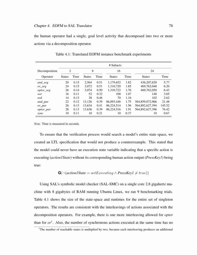
Chapter 4. EOFM to SAL Translator 78
the human operator had a single, goal level activity that decomposed into two or more
actions via a decomposition operator.
Table 4.1: Translated EOFM instance benchmark experiments
# Subacts
Decomposition 2 8 16 24
Operator States Time States Time States Time States Time
and_seq 20 0.15 2,564 0.51 1,179,652 1.82 436,207,620 5.77or_seq 24 0.15 3,072 0.51 1,310,720 1.85 469,762,048 6.20optor_seq 26 0.14 3,074 0.50 1,310,722 1.76 469,762,050 6.43xor 16 0.11 52 0.32 100 1.07 148 3.05ord 14 0.13 38 0.46 70 1.16 102 2.62and_par 22 0.12 13,126 0.39 86,093,446 1.75 564,859,072,966 21.48or_par 26 0.13 13,634 0.41 86,224,514 1.56 564,892,627,394 145.52optor_par 28 0.13 13,636 0.39 86,224,516 1.91 564,892,627,396 76.42sync 10 0.11 10 0.21 10 0.37 10 0.67
Note. Time is measured in seconds.
To ensure that the verification process would search a model’s entire state space, we
created an LTL specification that would not produce a counterexample. This stated that
the model could never have an execution state variable indicating that a specific action is
executing (action1State) without its corresponding human action output (PressKey1) being
true:
G(¬(action1State = actExecuting ∧ PressKey1 6= true))
Using SAL’s symbolic model checker (SAL-SMC) on a single core 2.8 gigahertz ma-
chine with 8 gigabytes of RAM running Ubuntu Linux, we ran 9 benchmarking trials.
Table 4.1 shows the size of the state-space and runtimes for the entire set of singleton
operators. The results are consistent with the interleavings of actions associated with the
decomposition operators. For example, there is one more interleaving allowed for optor
than for or1. Also, the number of synchronous actions executed at the same time has no1The number of reachable states is multiplied by two, because each interleaving produces an additional
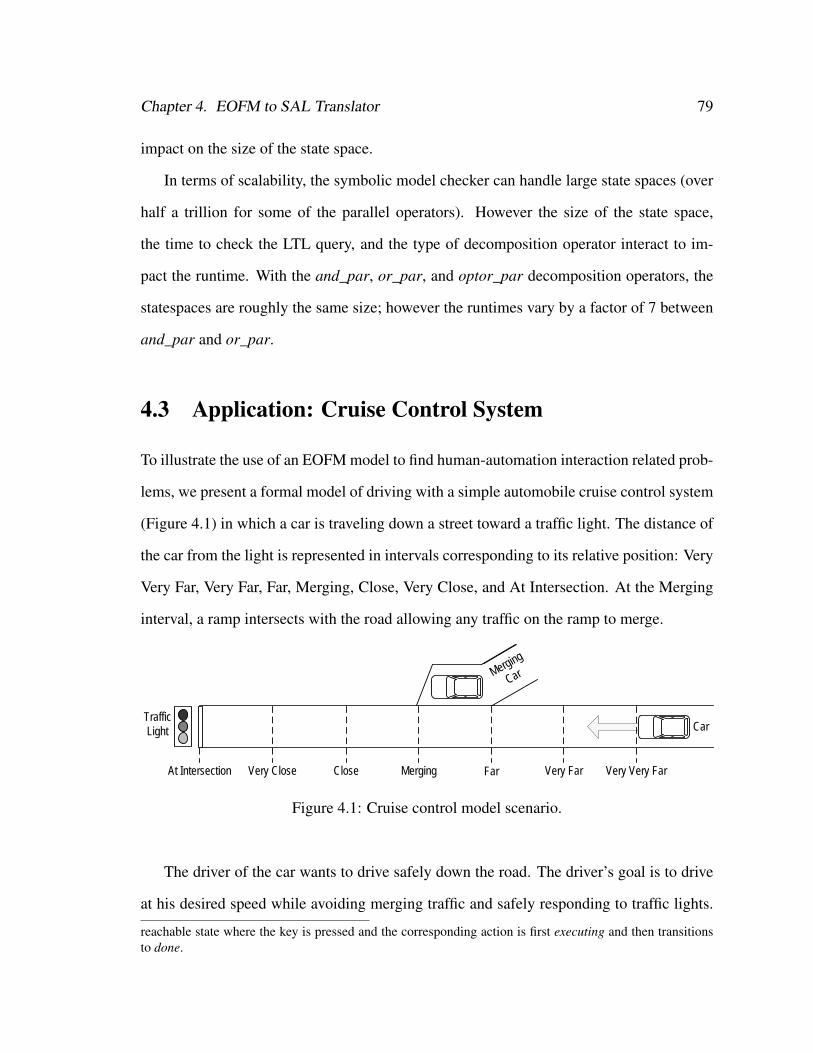
Chapter 4. EOFM to SAL Translator 79
impact on the size of the state space.
In terms of scalability, the symbolic model checker can handle large state spaces (over
half a trillion for some of the parallel operators). However the size of the state space,
the time to check the LTL query, and the type of decomposition operator interact to im-
pact the runtime. With the and_par, or_par, and optor_par decomposition operators, the
statespaces are roughly the same size; however the runtimes vary by a factor of 7 between
and_par and or_par.
4.3 Application: Cruise Control System
To illustrate the use of an EOFM model to find human-automation interaction related prob-
lems, we present a formal model of driving with a simple automobile cruise control system
(Figure 4.1) in which a car is traveling down a street toward a traffic light. The distance of
the car from the light is represented in intervals corresponding to its relative position: Very
Very Far, Very Far, Far, Merging, Close, Very Close, and At Intersection. At the Merging
interval, a ramp intersects with the road allowing any traffic on the ramp to merge.
At Intersection Very Close Close
Traffic Light Car
Merging Far Very Far Very Very Far
Merging
Car
Figure 4.1: Cruise control model scenario.
The driver of the car wants to drive safely down the road. The driver’s goal is to drive
at his desired speed while avoiding merging traffic and safely responding to traffic lights.
reachable state where the key is pressed and the corresponding action is first executing and then transitionsto done.
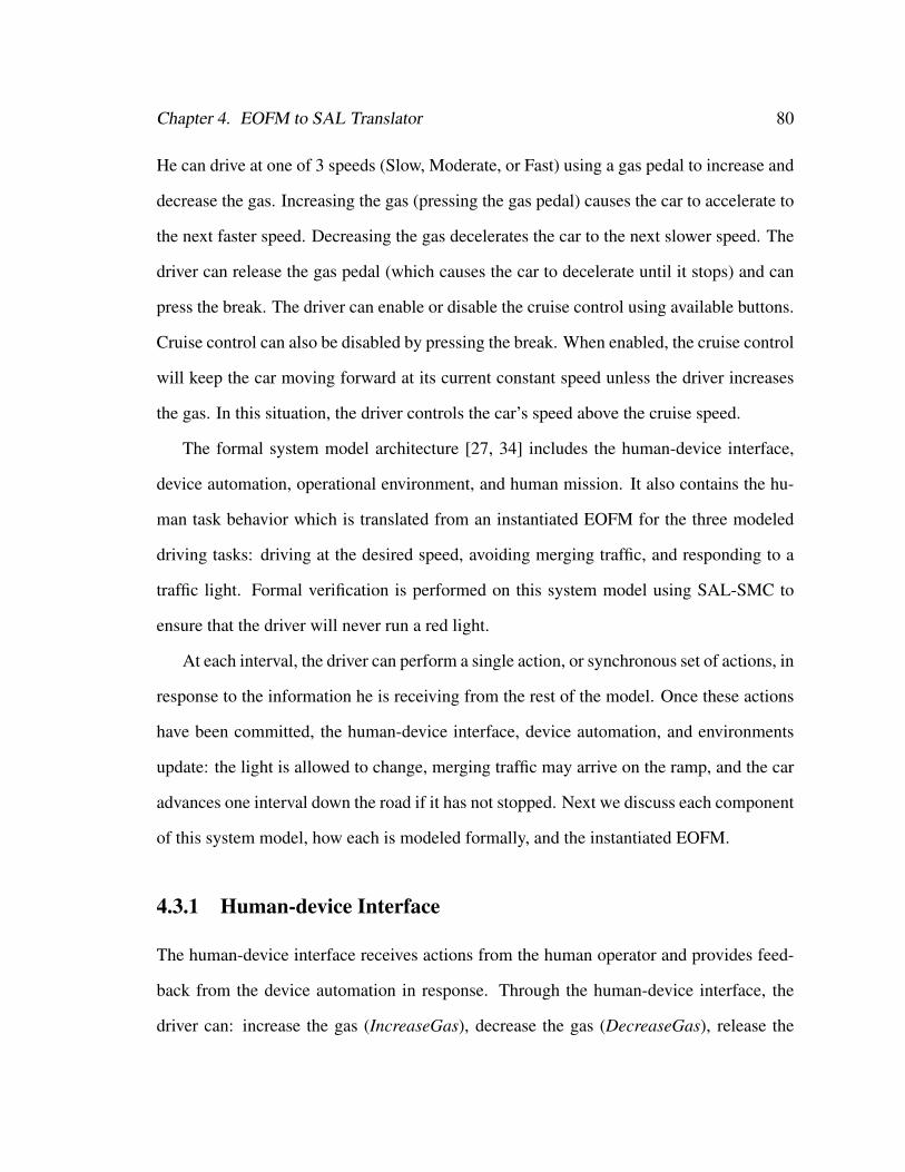
Chapter 4. EOFM to SAL Translator 80
He can drive at one of 3 speeds (Slow, Moderate, or Fast) using a gas pedal to increase and
decrease the gas. Increasing the gas (pressing the gas pedal) causes the car to accelerate to
the next faster speed. Decreasing the gas decelerates the car to the next slower speed. The
driver can release the gas pedal (which causes the car to decelerate until it stops) and can
press the break. The driver can enable or disable the cruise control using available buttons.
Cruise control can also be disabled by pressing the break. When enabled, the cruise control
will keep the car moving forward at its current constant speed unless the driver increases
the gas. In this situation, the driver controls the car’s speed above the cruise speed.
The formal system model architecture [27, 34] includes the human-device interface,
device automation, operational environment, and human mission. It also contains the hu-
man task behavior which is translated from an instantiated EOFM for the three modeled
driving tasks: driving at the desired speed, avoiding merging traffic, and responding to a
traffic light. Formal verification is performed on this system model using SAL-SMC to
ensure that the driver will never run a red light.
At each interval, the driver can perform a single action, or synchronous set of actions, in
response to the information he is receiving from the rest of the model. Once these actions
have been committed, the human-device interface, device automation, and environments
update: the light is allowed to change, merging traffic may arrive on the ramp, and the car
advances one interval down the road if it has not stopped. Next we discuss each component
of this system model, how each is modeled formally, and the instantiated EOFM.
4.3.1 Human-device Interface
The human-device interface receives actions from the human operator and provides feed-
back from the device automation in response. Through the human-device interface, the
driver can: increase the gas (IncreaseGas), decrease the gas (DecreaseGas), release the
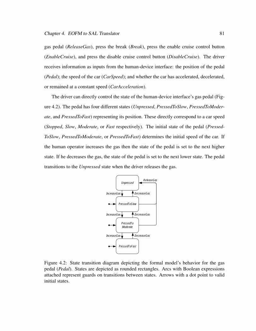
Chapter 4. EOFM to SAL Translator 81
gas pedal (ReleaseGas), press the break (Break), press the enable cruise control button
(EnableCruise), and press the disable cruise control button (DisableCruise). The driver
receives information as inputs from the human-device interface: the position of the pedal
(Pedal); the speed of the car (CarSpeed); and whether the car has accelerated, decelerated,
or remained at a constant speed (CarAcceleration).
The driver can directly control the state of the human-device interface’s gas pedal (Fig-
ure 4.2). The pedal has four different states (Unpressed, PressedToSlow, PressedToModer-
ate, and PressedToFast) representing its position. These directly correspond to a car speed
(Stopped, Slow, Moderate, or Fast respectively). The initial state of the pedal (Pressed-
ToSlow, PressedToModerate, or PressedToFast) determines the initial speed of the car. If
the human operator increases the gas then the state of the pedal is set to the next higher
state. If he decreases the gas, the state of the pedal is set to the next lower state. The pedal
transitions to the Unpressed state when the driver releases the gas.
Unpressed
PressedToSlow
PressedToModerate
PressedToFast
IncreaseGas
IncreaseGas
IncreaseGas
DecreaseGas
DecreaseGas
DecreaseGas
ReleaseGas
Figure 4.2: State transition diagram depicting the formal model’s behavior for the gaspedal (Pedal). States are depicted as rounded rectangles. Arcs with Boolean expressionsattached represent guards on transitions between states. Arrows with a dot point to validinitial states.
Chapter 4. EOFM to SAL Translator 82
4.3.2 Device Automation
The device automation tracks the status of the cruise control (Figure 4.3). Cruise is Enabled
when the driver presses the enable cruise button and Disabled when he presses the disable
cruise button or presses the break.
Enabled
Disabled
EnableCruise DisableCruise OR Break
Figure 4.3: State transition diagram depicting the formal model’s behavior for the state ofthe cruise control (Cruise). States are depicted as rounded rectangles. Arcs with Booleanexpressions attached represent guards on transitions between states. Arrows with a dotpoint to valid initial states.
Enabling the cruise control also sets the cruise speed in the device’s automation (Fig-
ure 4.4) where the cruise speed directly corresponds to the speed of the car when cruise is
enabled.
Human operator input to the gas pedal and the state of the cruise control also impact
how the device automation controls the speed of the car (Figure 4.5): a property visible
to the human operator via the speedometer. The driver can increase the car’s speed by
increasing the gas even when the cruise control is enabled. The application of the break
stops the car. When the driver decreases the gas (without applying the break), the car’s
speed decreases when Cruise is Disabled or when Cruise is Enabled and the CruiseSpeed is
below the car’s current speed. When the driver removes his foot from the gas (as indicated
by the Pedal being Unpressed), the car slows by two speed increments below the current
speed unless Cruise is Enabled and at an intermediary speed. In this case, the car will
remain at or slow down to the CruiseSpeed.
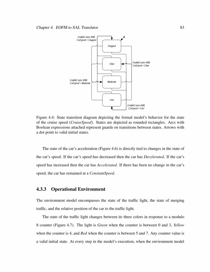
Chapter 4. EOFM to SAL Translator 83
EnableCruise AND CarSpeed = Moderate
EnableCruise AND CarSpeed = Stopped
EnableCruise AND CarSpeed = Fast
Stopped
Slow
Moderate
Fast
EnableCruise AND CarSpeed = Slow
Figure 4.4: State transition diagram depicting the formal model’s behavior for the stateof the cruise speed (CruiseSpeed). States are depicted as rounded rectangles. Arcs withBoolean expressions attached represent guards on transitions between states. Arrows witha dot point to valid initial states.
The state of the car’s acceleration (Figure 4.6) is directly tied to changes in the state of
the car’s speed. If the car’s speed has decreased then the car has Decelerated. If the car’s
speed has increased then the car has Accelerated. If there has been no change in the car’s
speed, the car has remained at a ConstantSpeed.
4.3.3 Operational Environment
The environment model encompasses the state of the traffic light, the state of merging
traffic, and the relative position of the car to the traffic light.
The state of the traffic light changes between its three colors in response to a modulo
8 counter (Figure 4.7). The light is Green when the counter is between 0 and 3, Yellow
when the counter is 4, and Red when the counter is between 5 and 7. Any counter value is
a valid initial state. At every step in the model’s execution, when the environment model
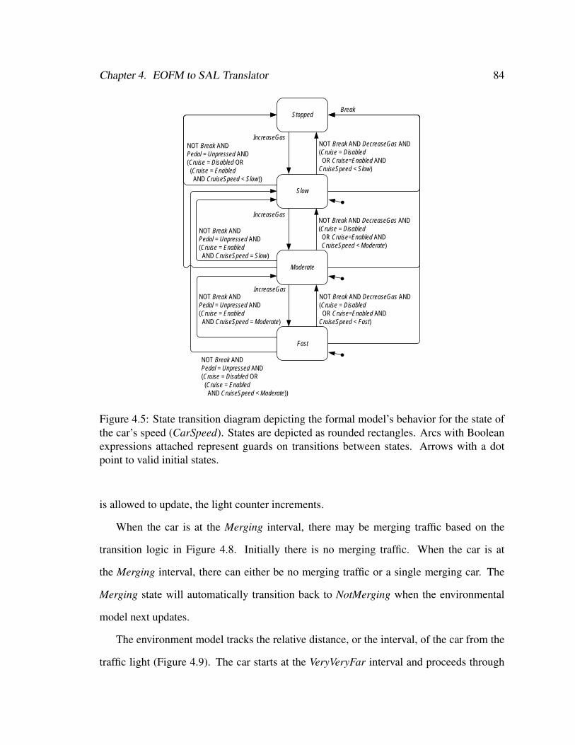
Chapter 4. EOFM to SAL Translator 84
Stopped
Slow
Moderate
Fast
IncreaseGas
IncreaseGas
IncreaseGas
Break
NOT Break AND DecreaseGas AND(Cruise = Disabled OR Cruise=Enabled AND
CruiseSpeed < Slow)
NOT Break AND DecreaseGas AND(Cruise = Disabled OR Cruise=Enabled AND
CruiseSpeed < Moderate)
NOT Break AND DecreaseGas AND(Cruise = Disabled OR Cruise=Enabled AND
CruiseSpeed < Fast)
NOT Break AND Pedal = Unpressed AND (Cruise = Disabled OR(Cruise = Enabled AND CruiseSpeed < Moderate))
NOT Break AND Pedal = Unpressed AND (Cruise = Disabled OR(Cruise = Enabled AND CruiseSpeed < Slow))
NOT Break ANDPedal = Unpressed AND(Cruise = Enabled AND CruiseSpeed = Moderate)
NOT Break ANDPedal = Unpressed AND(Cruise = Enabled AND CruiseSpeed = Slow)
Figure 4.5: State transition diagram depicting the formal model’s behavior for the state ofthe car’s speed (CarSpeed). States are depicted as rounded rectangles. Arcs with Booleanexpressions attached represent guards on transitions between states. Arrows with a dotpoint to valid initial states.
is allowed to update, the light counter increments.
When the car is at the Merging interval, there may be merging traffic based on the
transition logic in Figure 4.8. Initially there is no merging traffic. When the car is at
the Merging interval, there can either be no merging traffic or a single merging car. The
Merging state will automatically transition back to NotMerging when the environmental
model next updates.
The environment model tracks the relative distance, or the interval, of the car from the
traffic light (Figure 4.9). The car starts at the VeryVeryFar interval and proceeds through
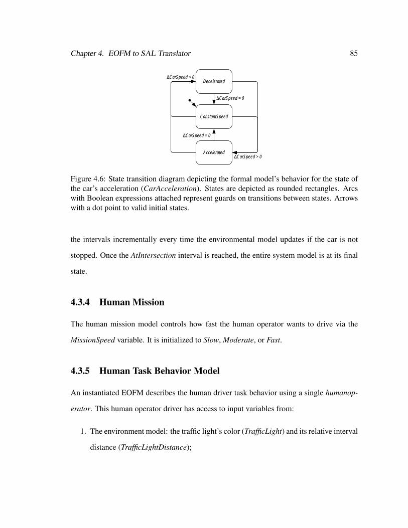
Chapter 4. EOFM to SAL Translator 85
ConstantSpeed
AcceleratedΔCarSpeed > 0
DeceleratedΔCarSpeed < 0
ΔCarSpeed = 0
ΔCarSpeed = 0
Figure 4.6: State transition diagram depicting the formal model’s behavior for the state ofthe car’s acceleration (CarAcceleration). States are depicted as rounded rectangles. Arcswith Boolean expressions attached represent guards on transitions between states. Arrowswith a dot point to valid initial states.
the intervals incrementally every time the environmental model updates if the car is not
stopped. Once the AtIntersection interval is reached, the entire system model is at its final
state.
4.3.4 Human Mission
The human mission model controls how fast the human operator wants to drive via the
MissionSpeed variable. It is initialized to Slow, Moderate, or Fast.
4.3.5 Human Task Behavior Model
An instantiated EOFM describes the human driver task behavior using a single humanop-
erator. This human operator driver has access to input variables from:
1. The environment model: the traffic light’s color (TrafficLight) and its relative interval
distance (TrafficLightDistance);
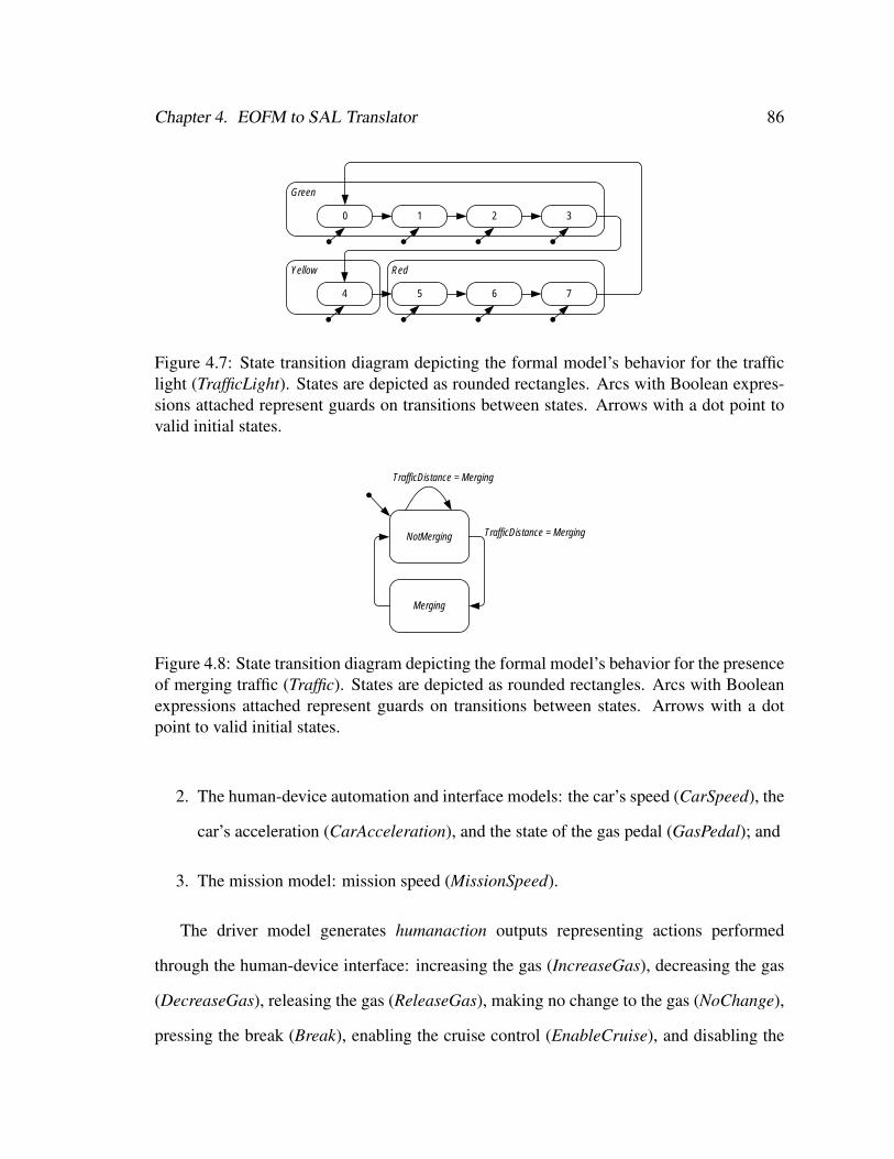
Chapter 4. EOFM to SAL Translator 86
Yellow Red
Green
0 1 2 3
4 5 6 7
Figure 4.7: State transition diagram depicting the formal model’s behavior for the trafficlight (TrafficLight). States are depicted as rounded rectangles. Arcs with Boolean expres-sions attached represent guards on transitions between states. Arrows with a dot point tovalid initial states.
NotMerging
Merging
TrafficDistance = Merging
TrafficDistance = Merging
Figure 4.8: State transition diagram depicting the formal model’s behavior for the presenceof merging traffic (Traffic). States are depicted as rounded rectangles. Arcs with Booleanexpressions attached represent guards on transitions between states. Arrows with a dotpoint to valid initial states.
2. The human-device automation and interface models: the car’s speed (CarSpeed), the
car’s acceleration (CarAcceleration), and the state of the gas pedal (GasPedal); and
3. The mission model: mission speed (MissionSpeed).
The driver model generates humanaction outputs representing actions performed
through the human-device interface: increasing the gas (IncreaseGas), decreasing the gas
(DecreaseGas), releasing the gas (ReleaseGas), making no change to the gas (NoChange),
pressing the break (Break), enabling the cruise control (EnableCruise), and disabling the
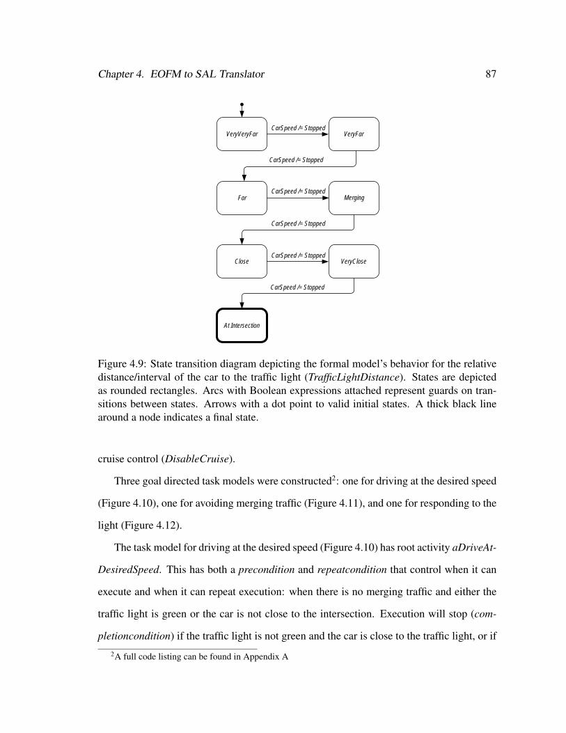
Chapter 4. EOFM to SAL Translator 87
VeryVeryFar VeryFarCarSpeed /= Stopped
Far
CarSpeed /= Stopped
MergingCarSpeed /= Stopped
Close VeryCloseCarSpeed /= Stopped
At Intersection
CarSpeed /= Stopped
CarSpeed /= Stopped
Figure 4.9: State transition diagram depicting the formal model’s behavior for the relativedistance/interval of the car to the traffic light (TrafficLightDistance). States are depictedas rounded rectangles. Arcs with Boolean expressions attached represent guards on tran-sitions between states. Arrows with a dot point to valid initial states. A thick black linearound a node indicates a final state.
cruise control (DisableCruise).
Three goal directed task models were constructed2: one for driving at the desired speed
(Figure 4.10), one for avoiding merging traffic (Figure 4.11), and one for responding to the
light (Figure 4.12).
The task model for driving at the desired speed (Figure 4.10) has root activity aDriveAt-
DesiredSpeed. This has both a precondition and repeatcondition that control when it can
execute and when it can repeat execution: when there is no merging traffic and either the
traffic light is green or the car is not close to the intersection. Execution will stop (com-
pletioncondition) if the traffic light is not green and the car is close to the traffic light, or if
2A full code listing can be found in Appendix A
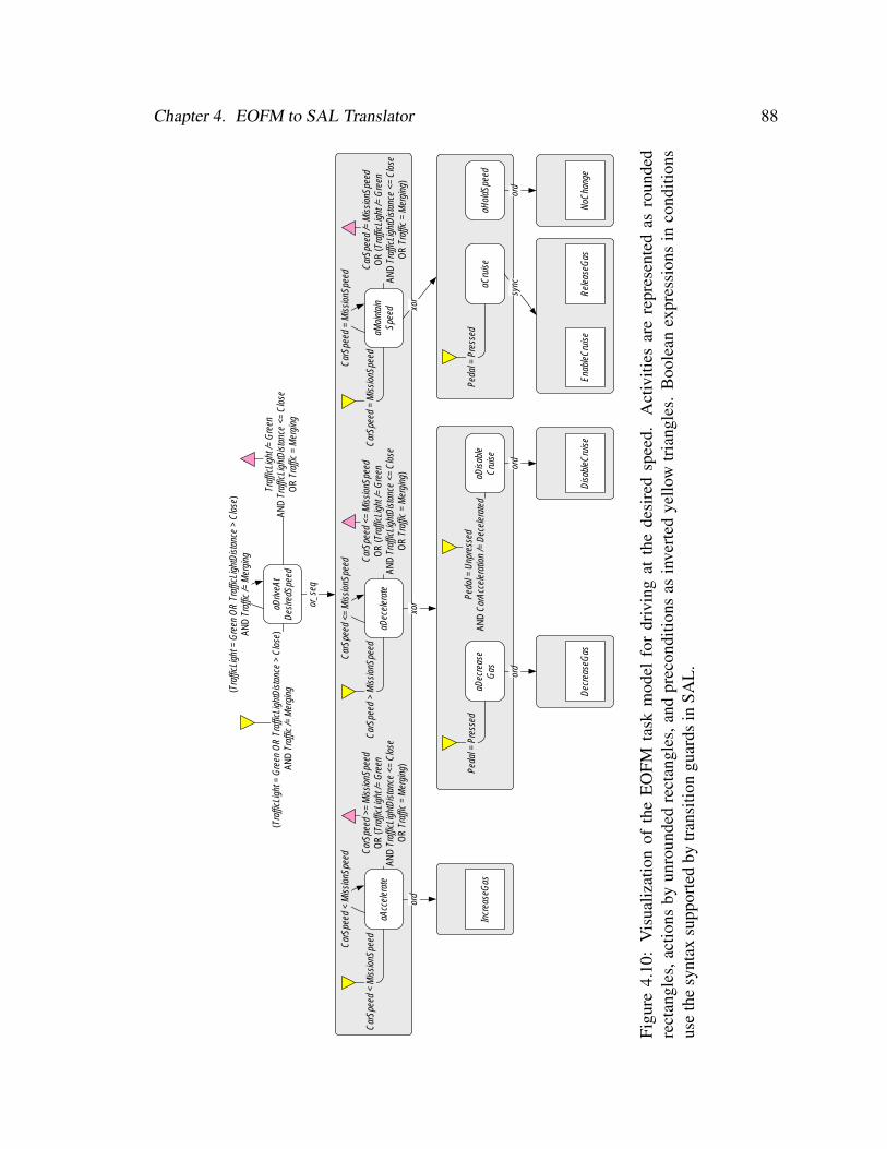
Chapter 4. EOFM to SAL Translator 88
aDriv
eAt
Des
iredS
peed
(Tra
fficL
ight
= G
reen
OR
Tra
fficL
ight
Dis
tanc
e >
Clo
se)
AND
Tra
ffic
/= M
ergi
ng(Tra
fficL
ight
= G
reen
OR
Tra
fficL
ight
Dis
tanc
e >
Clo
se)
AND
Tra
ffic
/= M
ergi
ng
Traf
ficLi
ght /
= G
reen
AN
D T
raffi
cLig
htD
ista
nce
<= C
lose
O
R T
raffi
c =
Mer
ging
or_s
eq
aAcc
eler
ate
Car
Spee
d <
Mis
sion
Spee
d
Car
Spee
d <
Mis
sion
Spee
d Car
Spee
d >=
Mis
sion
Spee
d O
R (T
raffi
cLig
ht /=
Gre
en
AND
Tra
fficL
ight
Dis
tanc
e <=
Clo
se
OR
Tra
ffic
= M
ergi
ng)
ord
Incr
ease
Gas
aDec
eler
ate
Car
Spee
d >
Mis
sion
Spee
d
Car
Spee
d <=
Mis
sion
Spee
d Car
Spee
d <=
Mis
sion
Spee
d O
R (T
raffi
cLig
ht /=
Gre
en
AND
Tra
fficL
ight
Dis
tanc
e <=
Clo
se
OR
Tra
ffic
= M
ergi
ng)
xor
aDec
reas
eG
as
Peda
l = P
ress
ed
ord
Dec
reas
eGas
aDis
able
Cru
ise
Peda
l = U
npre
ssed
AN
D C
arAc
cele
ratio
n /=
Dec
eler
ated
ord
Dis
able
Cru
ise
aMai
ntai
nSp
eed
Car
Spee
d =
Mis
sion
Spee
d
Car
Spee
d =
Mis
sion
Spee
d Car
Spee
d /=
Mis
sion
Spee
d O
R (T
raffi
cLig
ht /=
Gre
en
AND
Tra
fficL
ight
Dis
tanc
e <=
Clo
se
OR
Tra
ffic
= M
ergi
ng)
xor
aCru
ise
Peda
l = P
ress
ed
sync
Enab
leC
ruis
eR
elea
seG
as
aHol
dSpe
ed
ord
NoC
hang
e
Figu
re4.
10:
Vis
ualiz
atio
nof
the
EO
FMta
skm
odel
for
driv
ing
atth
ede
sire
dsp
eed.
Act
iviti
esar
ere
pres
ente
das
roun
ded
rect
angl
es,a
ctio
nsby
unro
unde
dre
ctan
gles
,and
prec
ondi
tions
asin
vert
edye
llow
tria
ngle
s.B
oole
anex
pres
sion
sin
cond
ition
sus
eth
esy
ntax
supp
orte
dby
tran
sitio
ngu
ards
inSA
L.
Chapter 4. EOFM to SAL Translator 89
traffic is merging.
The driver performs this activity using one or more methods (the or_seq decomposition
operator): accelerating (aAccelerate), decelerating (aDecelerate), or maintaining the cur-
rent speed (aMaintainSpeed). Accelerating can be performed repeatedly if the car’s speed
is less than the mission speed. This activity completes when the car’s speed reaches or
surpasses the mission speed, or if the driver must respond to the light or merging traffic.
The driver accelerates by increasing the gas (the ord decomposition operator indicates a
sequential order; but with one action, only the one action is performed).
The driver can start or continue decelerating if the car’s speed is greater than the desired
(mission) speed. The activity completes when the car’s speed is less than or equal to
the desired speed, or the driver needs to respond to the light or traffic. Deceleration is
accomplished by one of two activities (the xor decomposition operator): decreasing the
gas (aDecreaseGas) or disabling the cruise control (aDisableCruise). If the gas pedal is
pressed, the driver can decrease the gas. The driver can disable the cruise control if it is
enabled: the pedal is not pressed and the car has not just decelerated.
The driver can maintain speed as long as the car’s speed matches the desired speed. The
activity completes if the car’s speed does not match the desired speed, or the driver needs
to respond to the light or traffic. The driver maintains speed by either enabling the cruise
(aCruise) or holding the current speed (aHoldSpeed). If the cruise control does not appear
to be enabled (indicated by the pedal being pressed), it can be enabled by synchronously
performing (the sync decomposition operator) the actions for enabling the cruise control
and releasing the gas pedal. The driver can tell that the cruise control has been enabled if
the car does not decelerate when he removes his foot from the gas pedal. The driver holds
the current speed by making no change to the gas pedal.
The driver can avoid merging traffic (aAvoidMergingTraffic; Figure 4.11) when traffic
is merging by performing one of two activities: if the car is not at its minimum speed, the

Chapter 4. EOFM to SAL Translator 90
driver can let the merging traffic go in front (aLetCarGoInFront), or if the car is not at
its maximum speed, the driver can let the merging traffic in behind (aLetCarGoBehind).
Letting the traffic pull in front is achieved by (a) decreasing the gas (via aDecreaseGas) if
cruise is not enabled or (b) disabling cruise (via aDisableCruise) if it is enabled. Letting
the traffic in behind is achieved by increasing the gas.
aAvoidMergingTraffic
Traffic = Merging
xor
aLetCarGoInFront
CarSpeed > Slow
xor
aDecreaseGas
Pedal = Pressed
ord
DecreaseGas
aDisableCruise
Pedal = Unpressed AND CarAcceleration /= Decelerated
ord
DisableCruise
aLetCarGoBehind
CarSpeed < Fast
ord
IncreaseGas
Figure 4.11: Visualization of the EOFM for avoiding to merging traffic.
The driver responds to the traffic light (aRespondToLight in Figure 4.12) if the traffic
light is not green and the car is close or very close to it by performing one or more of
three activities: waiting to respond to the light until the car is closer (aWaitTillCloser),
performing a break stop (aBreakStop), or performing a roll stop (aRollStop). If the car is
close to the traffic light, the driver can wait until the light is closer by making no change to
the car’s gas pedal.
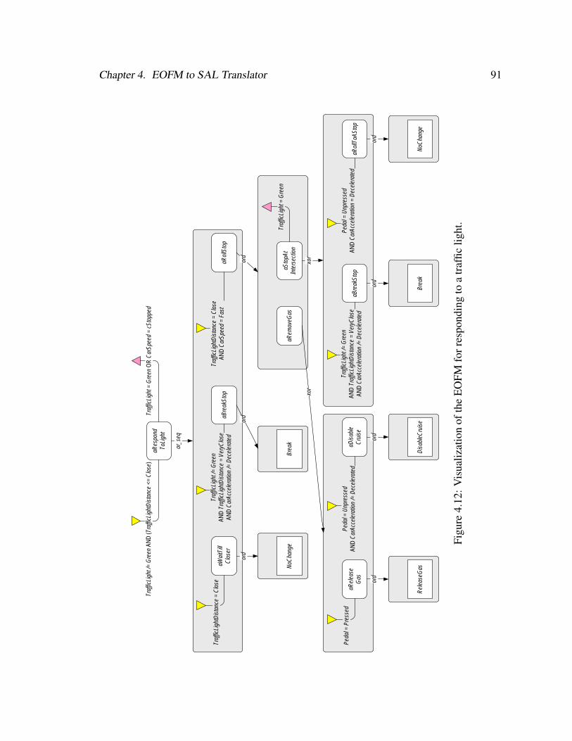
Chapter 4. EOFM to SAL Translator 91
aRes
pond
ToLi
ght
Traf
ficLi
ght /
= G
reen
AN
D (T
raffi
cLig
htD
ista
nce
<= C
lose
)Tr
affic
Ligh
t = G
reen
OR
Car
Spee
d =
cSto
pped
or_s
eq
aWai
tTill
Clo
ser
Traf
ficLi
ghtD
ista
nce
= C
lose
ord
NoC
hang
e
aBre
akSt
op
Traf
ficLi
ght /
= G
reen
AN
D T
raffi
cLig
htD
ista
nce
= Ve
ryC
lose
AN
D C
arAc
cele
ratio
n /=
Dec
eler
ated
ord
Brea
k
aRol
lSto
p
Traf
ficLi
ghtD
ista
nce
= C
lose
AN
D C
arSp
eed
= Fa
st
ord
aRem
oveG
as
xor
aRel
ease
Gas
Peda
l = P
ress
ed
ord
Rel
ease
Gas
aDis
able
Cru
ise
Peda
l = U
npre
ssed
AN
D C
arAc
cele
ratio
n /=
Dec
eler
ated
ord
Dis
able
Cru
ise
aSto
pAt
Inte
rsec
tion
Traf
ficLi
ght =
Gre
en
xor
aBre
akSt
op
Traf
ficLi
ght /
= G
reen
AN
D T
raffi
cLig
htD
ista
nce
= Ve
ryC
lose
AN
D C
arAc
cele
ratio
n /=
Dec
eler
ated
ord
Brea
k
aRol
lToA
Stop
Peda
l = U
npre
ssed
AN
D C
arAc
cele
ratio
n =
Dec
eler
ated
ord
NoC
hang
e
Figu
re4.
12:V
isua
lizat
ion
ofth
eE
OFM
forr
espo
ndin
gto
atr
affic
light
.
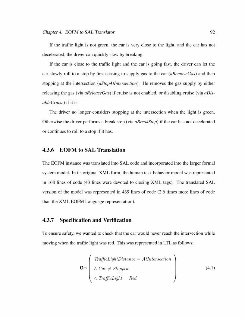
Chapter 4. EOFM to SAL Translator 92
If the traffic light is not green, the car is very close to the light, and the car has not
decelerated, the driver can quickly slow by breaking.
If the car is close to the traffic light and the car is going fast, the driver can let the
car slowly roll to a stop by first ceasing to supply gas to the car (aRemoveGas) and then
stopping at the intersection (aStopAtIntersection). He removes the gas supply by either
releasing the gas (via aReleaseGas) if cruise is not enabled, or disabling cruise (via aDis-
ableCruise) if it is.
The driver no longer considers stopping at the intersection when the light is green.
Otherwise the driver performs a break stop (via aBreakStop) if the car has not decelerated
or continues to roll to a stop if it has.
4.3.6 EOFM to SAL Translation
The EOFM instance was translated into SAL code and incorporated into the larger formal
system model. In its original XML form, the human task behavior model was represented
in 168 lines of code (43 lines were devoted to closing XML tags). The translated SAL
version of the model was represented in 439 lines of code (2.6 times more lines of code
than the XML EOFM Language representation).
4.3.7 Specification and Verification
To ensure safety, we wanted to check that the car would never reach the intersection while
moving when the traffic light was red. This was represented in LTL as follows:
G¬
TrafficLightDistance = AtIntersection
∧ Car 6= Stopped
∧ TrafficLight = Red
(4.1)
Chapter 4. EOFM to SAL Translator 93
The attempt to verify this specification using SAL-SMC resulted in a counterexample
illustrating a violation. This occurred as follows:
1. The car starts VeryVeryFar from the traffic light going Slow with a ConstantSpeed
acceleration. The pedal is PressedToSlow and cruise is Disabled. The traffic light is
Green and the driver wants to maintain a Moderate speed.
2. Because the current speed is too slow, the driver increases his speed by increasing
the gas (IncreaseGas via the aDriveAtDesiredSpeed and aAccelerate activities; Fig-
ure 4.10). The car proceeds to the VeryFar interval having Accelerated to a Moderate
speed.
3. Now at his desired speed, the driver engages the cruise control (synchronously per-
forming EnableCruise and ReleaseGas via the aDriveAtDesiredSpeed, aMaintain-
Speed, and aCruise activities; Figure 4.10). The car thus proceeds to the Far position
at a Moderate ConstantSpeed.
4. The driver makes no changes to the speed of the car (NoChange via the aDriveAt-
DesiredSpeed, aMaintainSpeed, and aHoldSpeed activities). The car proceeds to the
Merging position at a Moderate ConstantSpeed, where traffic is attempting to merge.
5. The driver lets the traffic in behind by increasing the gas (IncreaseGas via the
aAvoidMergingTraffic and aLetCarGoBehind activities; Figure 4.11). The car ad-
vances to the Close interval having Accelerated to the Fast speed. The traffic light
turns Yellow.
6. The driver responds to the light by executing releasing his foot from the gas to per-
form a roll stop (ReleaseGas via the aRespondToLight, aRollStop, aRemoveGas, and
aReleaseGas activities; Figure 4.12). The car proceeds to the VeryClose interval hav-
ing Decelerated to the Slow speed. The light turns Red.
Chapter 4. EOFM to SAL Translator 94
7. Having felt the car decelerate when he released the gas, the driver attempts to con-
tinue rolling to a stop at the intersection by making no change (NoChange via the
aRespondToLight, aRollStop, aStopAtIntersection, and aRollToAStop activities; Fig-
ure 4.12). However, the car has reached its cruising speed (Moderate) and has con-
tinued to the AtIntersection interval at a Moderate ConstantSpeed.
Thus the specification has been violated with the car reaching the intersection without
having stopped when the light is red.
4.3.8 Redesign
We can use our methodology to explore potential solutions to the discovered problem. A
possible explanation for the above problem is that the driver does not remember that the
cruise control is engaged and therefore cannot properly perform a roll stop. In the current
implementation, the only way the driver can tell that the cruise control is engaged is if the
gas pedal is not pressed and the car is not decelerating.
The car designer can add an indicator light with the state of the cruise control. In
the formal model, this can be represented by a new variable (Cruising) which indicates
whether cruise control is Enabled or Disabled. The driver’s task model then changes to
check this variable before executing a roll stop. To model this change a Cruising input-
variable node is added to the driver’s humanoperator node. In the aDriveAtDesiredSpeed
activity (Figure 4.10) the preconditions for aDecreaseGas and aCruise check that cruis-
ing is Disabled and the precondition for aDisableCruise checks that cruise is Enabled.
In the aAvoidMergingTraffic (Figure 4.11) activity, the precondition on aDecreaseGas and
aDisableCruise check that cruise is Disabled and Enabled respectively. Finally, in the aRe-
spondToLight (Figure 4.12) activity, the precondition to aReleaseGas and aDisableCruise
check that cruise is Disabled and Enabled respectively. The decomposition of aDisable-
Chapter 4. EOFM to SAL Translator 95
Cruise also changes to the sync decomposition operator to support the actions for disabling
the cruise control and releasing the gas pedal.
An EOFM instantiation modified to reflect these changes was translated into SAL and
incorporated into the compatibly modified system model. When SAL-SMC was run using
this new model and the specification in 4.1, it verified to true. Thus the minor modifications
to the human-device interface and the human task behavior model eliminated the potential
human-automation interaction problem discovered in the previous verification.
4.4 Discussion
The EOFM task modeling language is defined formally and its formal description has
been used to construct a translator to support model checking. Translated models can be
incorporated into larger system models so that they can be formally verified. We have
demonstrated that this process can be used to discover and correct problems related to
human-automation interaction.
4.4.1 Benchmarking and Model Complexity
The reported benchmarks highlight the tradeoffs associated with modeling different tem-
poral orderings of human behavior. In order to assess this, one must qualify the frequency
that each decomposition operator is used in task analytic modeling, and in what contexts
each is most appropriate. This will help provide a better understanding of what types of
systems are best suited for the analysis presented here.
Bolton and Bass [31] indicate that, rather than add to the complexity of formal system
models, the formal representation of the human task models reduces model complexity
for systems that depend on human-automation interaction by constraining the reachable
state space to that associated with modeled human behavior. This suggests that the de-
Chapter 4. EOFM to SAL Translator 96
composition operators associated with higher model complexity in Table 4.1 would simply
fail to constrain the system model as tightly as the less complex decomposition operators.
This could limit the types of applications that can be formally verified using the method
discussed here. Future work should explore this possibility.
There may also be potential for reducing the state space complexity of the translated
EOFM models. In the current implementation, the formal model represents every transi-
tional step of an activity’s execution state as a single model transition in the formal model.
While this accurately adheres to the formal semantics of the language, it necessitates that
the formal model has a discrete state for every intermediary transition in the task model
hierarchy. These intermediary transitions are of no consequence to the other elements of
the system model, which are only concerned with the resulting human actions. Thus, the
complexity of the formal task model representation could be reduced by decreasing the
number of internal transitions required to traverse an instantiated EOFM’s translated task
structure during execution. Future work should investigate the feasibility of this.
4.4.2 Compactness of the EOFM Language
The increase in code size between the EOFM language representation and its translated
SAL code version illustrates how much more compact the EOFM language is for modeling
human task analytic behavior. This coupled with the fact that the EOFM language structure
closely mimics the hierarchical nature of the task analytic modeling paradigm suggests that
it may be easier to model human task behavior using the EOFM-like languages than with
native model checking code. Future work should investigate whether analysts can develop
task models more efficiently using EOFM. This is discussed in more thoroughly in Chapter
9.
Chapter 5
Phenotypical Erroneous Human
Behavior Generation∗
The discussion up to this point has used examples showing how our method can be used
with normative human task behavior models to find human-automation interaction related
system problems. However, many system failures involving human behavior occur (at least
partially) as a result of erroneous human behavior [12, 80, 105, 125, 126, 130, 144, 146,
158, 159, 168]. This chapter discusses the literature on the classification and modeling of
erroneous human behavior and discusses a way in which this can be used to describe the er-
roneous human behavior model generation process from the method, where phenotypes of
erroneous human behavior [100] are automatically incorporated into instantiated EOFMs.
This allows an analyst who is using our method to evaluate the impact of potentially un-
predicted erroneous human behavior on system safety properties. Our implementation is
validated, and benchmarks are provided to provide insight into how the analyses may scale
in relation to the number of generated erroneous behaviors. The process is also illustrated
with a radiation therapy machine application which makes use of the human mission, hu-
man task behavior, device automation, and human-device interface. The use of the gen-
∗This chapter is derived from [29]
97
Chapter 5. Phenotypical Erroneous Human Behavior Generation 98
erated erroneous human behavior in the formal system model resulted in a specification
violation. Changes to the device automation were able to eliminate this violation even with
the inclusion of the erroneous human behavior.
5.1 Erroneous Human Behavior Taxonomies
Erroneous behavior has been classified based on how they arise from human decision mak-
ing, cognition, and task execution [100, 142, 159]. Many classifications rely on a models
of cognition or decision making [142, 159]. However, Hollnagel [100] relies exclusively
on the observable manifestation of erroneous human behavior. Instantiated EOFMs do not
have to model the low level perceptual, motor, and cognitive processes but do model hu-
man task behavior hierarchically down to the atomic, observable action level. Thus they
are compatible with Hollnagel’s [100] phenotypes of erroneous action.
Hollnagel [100] classified erroneous human behavior based on how it observably man-
ifests as divergence from planned or normative sequences of actions. All erroneous be-
haviors are composed of one or more erroneous actions, all capable of being detected by
observing the performance of a single act in a plan. These “zero-order” phenotypes in-
clude: prematurely starting an action, delaying the start of an action, prematurely finishing
an action, delaying the completion of an action, omitting an action, skipping an action,
re-performing a previously performed action, repeating an action, and performing an un-
planned action (an intrusion). Higher order phenotypes are composed of two or more
zero-order phenotypes.
The phenotypes for delaying, prematurely starting, or prematurely finishing an action
specifically refer to time, not currently supported by formal verification with our method
[26]. However, all of the other zero-order phenotypes relate to the performance or non-
performance of actions, all supported by the formal semantics and structure of the EOFM.
Chapter 5. Phenotypical Erroneous Human Behavior Generation 99
In this work, we introduce a method that automatically generates these phenotypes as part
of an instantiated EOFM that captures normative behavior.
5.2 Automatic Phenotypical Erroneous Human Behavior
Generation
The error generation process must be capable of replicating Hollnagel’s 1993 zero-order
phenotypes of erroneous human behavior for omitting, skipping, re-performing, repeating
or intruding an action for each original action in an instantiated EOFM. To allow for more
complex erroneous human behaviors, error generation must be capable of chaining zero-
order erroneous human acts. Because an unbounded number of erroneous acts could result
in an unbounded human task behavior model, the error generation process must support
a mechanism for constraining the number of erroneous acts that can be performed in the
formally translated erroneous human behavior model. In order to facilitate analysis with
our method, the error generation structure should be represented in the EOFM language
thus making it compatible with EOFM to SAL translation process and counterexample
visulization.
To create and erroneous human behavior model, a pattern for generating zero-order
phenotypes for omissions, skips, re-performances, repetitions, and intrusions are incorpo-
rated into an instantiated EOFM by replacing each atomic action (Actionx) with a cus-
tomized structure (Actionx’) (Figure 5.1). This design includes an upper bound on the
number of erroneous acts (EMax) and a variable (ECount) that keeps track of the num-
ber of erroneous acts that the task model has performed. Any activity that represents an
erroneous act has a precondition asserting that it cannot be performed unless the current
number of performed erroneous actions is less than the maximum (ECount < EMax). Ev-
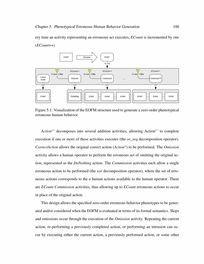
Chapter 5. Phenotypical Erroneous Human Behavior Generation 100
ery time an activity representing an erroneous act executes, ECount is incremented by one
(ECount++).
Actionx’
or_seq
CorrectAction
ord
Actionx
Omission
ECount < EMax
ord
DoNothing
Commission1
ECount < EMax
xor
. . .
ECount++ ECount++
. . .
BecomesActionx
Actionn
CommissionEMax
ECount < EMax
xor
ECount++
. . .Action1 Actionx . . . Actionn. . .Action1 Actionx
Figure 5.1: Visualization of the EOFM structure used to generate a zero-order phenotypicalerroneous human behavior.
Actionx’ decomposes into several addition activities, allowing Actionx’ to complete
execution if one or more of these activities executes (the or_seq decomposition operator).
CorrectAction allows the original correct action (Actionx) to be performed. The Omission
activity allows a human operator to perform the erroneous act of omitting the original ac-
tion, represented as the DoNothing action. The Commission activities each allow a single
erroneous action to be performed (the xor decomposition operator), where the set of erro-
neous actions corresponds to the n human actions available to the human operator. There
are ECount Commission activities, thus allowing up to ECount erroneous actions to occur
in place of the original action.
This design allows the specified zero-order erroneous behavior phenotypes to be gener-
ated and/or considered when the EOFM is evaluated in terms of its formal semantics. Skips
and omissions occur through the execution of the Omission activity. Repeating the current
action, re-performing a previously completed action, or performing an intrusion can oc-
cur by executing either the current action, a previously performed action, or some other
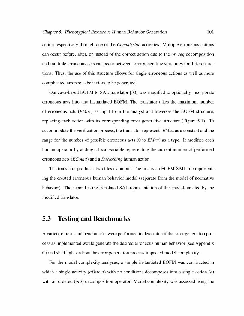
Chapter 5. Phenotypical Erroneous Human Behavior Generation 101
action respectively through one of the Commission activities. Multiple erroneous actions
can occur before, after, or instead of the correct action due to the or_seq decomposition
and multiple erroneous acts can occur between error generating structures for different ac-
tions. Thus, the use of this structure allows for single erroneous actions as well as more
complicated erroneous behaviors to be generated.
Our Java-based EOFM to SAL translator [33] was modified to optionally incorporate
erroneous acts into any instantiated EOFM. The translator takes the maximum number
of erroneous acts (EMax) as input from the analyst and traverses the EOFM structure,
replacing each action with its corresponding error generative structure (Figure 5.1). To
accommodate the verification process, the translator represents EMax as a constant and the
range for the number of possible erroneous acts (0 to EMax) as a type. It modifies each
human operator by adding a local variable representing the current number of performed
erroneous acts (ECount) and a DoNothing human action.
The translator produces two files as output. The first is an EOFM XML file represent-
ing the created erroneous human behavior model (separate from the model of normative
behavior). The second is the translated SAL representation of this model, created by the
modified translator.
5.3 Testing and Benchmarks
A variety of tests and benchmarks were performed to determine if the error generation pro-
cess as implemented would generate the desired erroneous human behavior (see Appendix
C) and shed light on how the error generation process impacted model complexity.
For the model complexity analyses, a simple instantiated EOFM was constructed in
which a single activity (aParent) with no conditions decomposes into a single action (a)
with an ordered (ord) decomposition operator. Model complexity was assessed using the
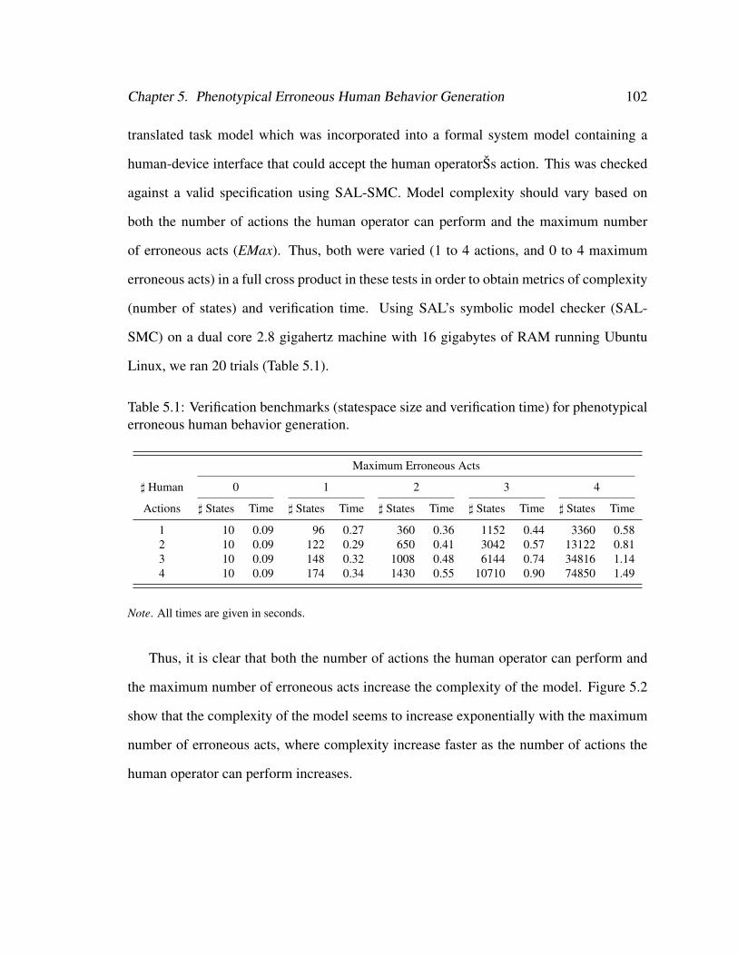
Chapter 5. Phenotypical Erroneous Human Behavior Generation 102
translated task model which was incorporated into a formal system model containing a
human-device interface that could accept the human operatorŠs action. This was checked
against a valid specification using SAL-SMC. Model complexity should vary based on
both the number of actions the human operator can perform and the maximum number
of erroneous acts (EMax). Thus, both were varied (1 to 4 actions, and 0 to 4 maximum
erroneous acts) in a full cross product in these tests in order to obtain metrics of complexity
(number of states) and verification time. Using SAL’s symbolic model checker (SAL-
SMC) on a dual core 2.8 gigahertz machine with 16 gigabytes of RAM running Ubuntu
Linux, we ran 20 trials (Table 5.1).
Table 5.1: Verification benchmarks (statespace size and verification time) for phenotypicalerroneous human behavior generation.
Maximum Erroneous Acts
] Human 0 1 2 3 4
Actions ] States Time ] States Time ] States Time ] States Time ] States Time
1 10 0.09 96 0.27 360 0.36 1152 0.44 3360 0.582 10 0.09 122 0.29 650 0.41 3042 0.57 13122 0.813 10 0.09 148 0.32 1008 0.48 6144 0.74 34816 1.144 10 0.09 174 0.34 1430 0.55 10710 0.90 74850 1.49
Note. All times are given in seconds.
Thus, it is clear that both the number of actions the human operator can perform and
the maximum number of erroneous acts increase the complexity of the model. Figure 5.2
show that the complexity of the model seems to increase exponentially with the maximum
number of erroneous acts, where complexity increase faster as the number of actions the
human operator can perform increases.
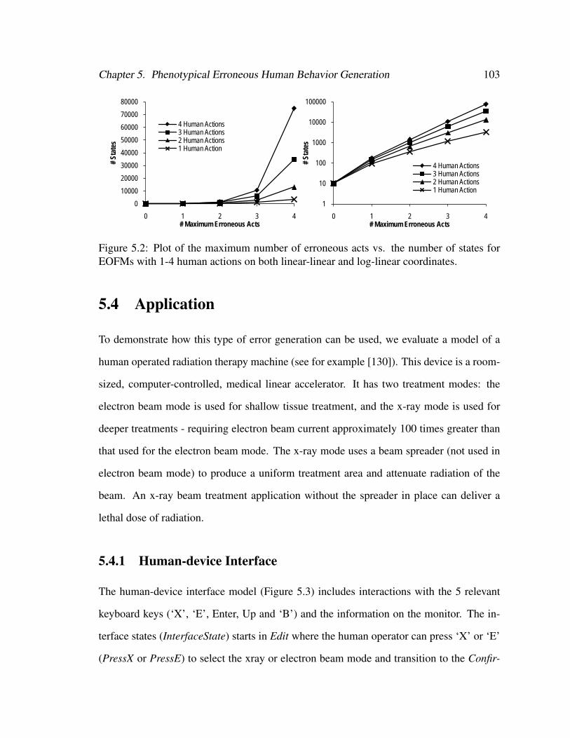
Chapter 5. Phenotypical Erroneous Human Behavior Generation 103
0 1 2 3 4 1 2
4 Human A 10 174 1430 10710 74850 0.09 0.273 Human A 10 148 1008 6144 34816 0.09 0.292 Human A 10 122 650 3042 13122 0.09 0.321 Human A 10 96 360 1152 3360 0.09 0.34
1 Human A 2 Human A 3 Human A 4 Human Actions 1 Human A 2 Human A0 Maximum 10 10 10 10 10 10
1 Maximum 96 122 148 174 96 122
2 Maximum 360 650 1008 1430 360 6503 Maximum 1152 3042 6144 10710 1152 30424 Maximum 3360 13122 34816 74850 3360 13122
1
10
100
1000
10000
100000
0 1 2 3 4
# St
ates
# Maximum Erroneous Acts
4 Human Actions3 Human Actions2 Human Actions1 Human Action
0
10000
20000
30000
40000
50000
60000
70000
80000
0 1
# St
ates
# Maximum
4 Human Act3 Human Act2 Human Act1 Human Act
0
10000
20000
30000
40000
50000
60000
70000
80000
0 1 2 3 4
# St
ates
# Maximum Erroneous Acts
4 Human Actions3 Human Actions2 Human Actions1 Human Action
1
10
100
1000
10000
100000
0 1 2 3 4
# St
ates
# Maximum Erroneous Acts
4 Human Actions3 Human Actions2 Human Actions1 Human Action
Figure 5.2: Plot of the maximum number of erroneous acts vs. the number of states forEOFMs with 1-4 human actions on both linear-linear and log-linear coordinates.
5.4 Application
To demonstrate how this type of error generation can be used, we evaluate a model of a
human operated radiation therapy machine (see for example [130]). This device is a room-
sized, computer-controlled, medical linear accelerator. It has two treatment modes: the
electron beam mode is used for shallow tissue treatment, and the x-ray mode is used for
deeper treatments - requiring electron beam current approximately 100 times greater than
that used for the electron beam mode. The x-ray mode uses a beam spreader (not used in
electron beam mode) to produce a uniform treatment area and attenuate radiation of the
beam. An x-ray beam treatment application without the spreader in place can deliver a
lethal dose of radiation.
5.4.1 Human-device Interface
The human-device interface model (Figure 5.3) includes interactions with the 5 relevant
keyboard keys (‘X’, ‘E’, Enter, Up and ‘B’) and the information on the monitor. The in-
terface states (InterfaceState) starts in Edit where the human operator can press ‘X’ or ‘E’
(PressX or PressE) to select the xray or electron beam mode and transition to the Confir-
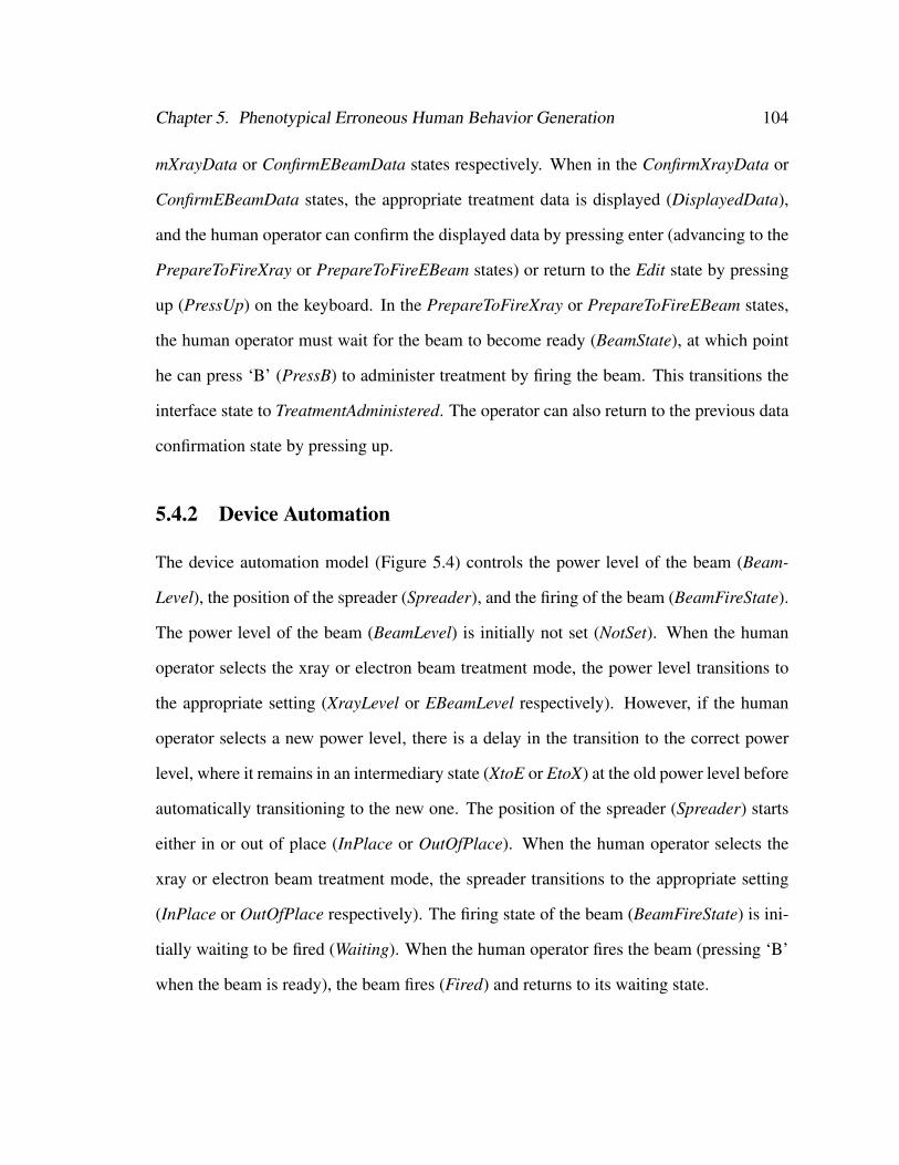
Chapter 5. Phenotypical Erroneous Human Behavior Generation 104
mXrayData or ConfirmEBeamData states respectively. When in the ConfirmXrayData or
ConfirmEBeamData states, the appropriate treatment data is displayed (DisplayedData),
and the human operator can confirm the displayed data by pressing enter (advancing to the
PrepareToFireXray or PrepareToFireEBeam states) or return to the Edit state by pressing
up (PressUp) on the keyboard. In the PrepareToFireXray or PrepareToFireEBeam states,
the human operator must wait for the beam to become ready (BeamState), at which point
he can press ‘B’ (PressB) to administer treatment by firing the beam. This transitions the
interface state to TreatmentAdministered. The operator can also return to the previous data
confirmation state by pressing up.
5.4.2 Device Automation
The device automation model (Figure 5.4) controls the power level of the beam (Beam-
Level), the position of the spreader (Spreader), and the firing of the beam (BeamFireState).
The power level of the beam (BeamLevel) is initially not set (NotSet). When the human
operator selects the xray or electron beam treatment mode, the power level transitions to
the appropriate setting (XrayLevel or EBeamLevel respectively). However, if the human
operator selects a new power level, there is a delay in the transition to the correct power
level, where it remains in an intermediary state (XtoE or EtoX) at the old power level before
automatically transitioning to the new one. The position of the spreader (Spreader) starts
either in or out of place (InPlace or OutOfPlace). When the human operator selects the
xray or electron beam treatment mode, the spreader transitions to the appropriate setting
(InPlace or OutOfPlace respectively). The firing state of the beam (BeamFireState) is ini-
tially waiting to be fired (Waiting). When the human operator fires the beam (pressing ‘B’
when the beam is ready), the beam fires (Fired) and returns to its waiting state.

Chapter 5. Phenotypical Erroneous Human Behavior Generation 105
Edit
ConfirmEBeamData
ConfirmXrayData
PrepareToFireEBeam
PrepareToFireXray
Treatment Administered
PressUp PressEnter
PressX PressE
PressEnter PressUp
BeamState = BeamReady ˄ PressB
BeamState = BeamReady ˄ PressB
NotReady Ready
InterfaceState = PrepareToFireXray˅ InterfaceState = PrepareToFireEBeam
InterfaceState ≠ PrepareToFireXray˅ InterfaceState ≠ PrepareToFireEBeam
InterfaceState
DisplayedData
NoData
EBeamDataXrayData
InterfaceState = Edit ˄ PressX
InterfaceState = Edit ˄ PressE
InterfaceState = ConfirmXrayData˄ PressUp
InterfaceState = ConfirmEBeamData˄ PressUp
BeamState
PressUpPressUp
Figure 5.3: State transition representation of the formal human-device interface model.Rounded rectangles represent states. Arrows between states represent transitions. Dottedarrows indicate initial states.
5.4.3 Human Mission
The human mission identifies the desired treatment (TreatmentType equaling Xray or
EBeam).
5.4.4 Human Task Behavior
Three goal directed task models describe the administration of treatment with the radiation
therapy machine (Figure 5.5): selecting the treatment mode (aSelectXorE), confirming
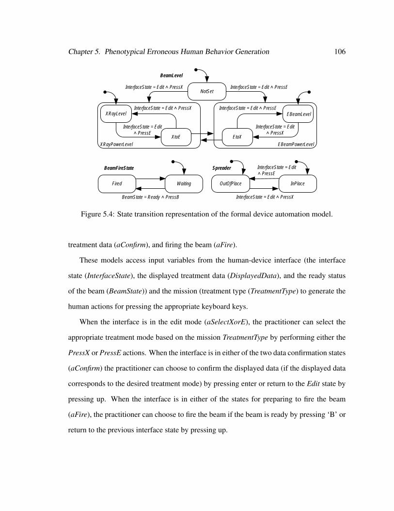
Chapter 5. Phenotypical Erroneous Human Behavior Generation 106
EBeamPowerLevelXRayPowerLevel
NotSet
XRayLevel
XtoE
EBeamLevel
EtoX
InterfaceState = Edit ˄ PressX InterfaceState = Edit ˄ PressE
InterfaceState = Edit ˄ PressE
InterfaceState = Edit ˄ PressX
InterfaceState = Edit ˄ PressX InterfaceState = Edit ˄ PressE
InterfaceState = Edit ˄ PressX
InterfaceState = Edit ˄ PressE
OutOfPlace InPlace
BeamState = Ready ˄ PressB
Fired Waiting
BeamLevel
SpreaderBeamFireState
Figure 5.4: State transition representation of the formal device automation model.
treatment data (aConfirm), and firing the beam (aFire).
These models access input variables from the human-device interface (the interface
state (InterfaceState), the displayed treatment data (DisplayedData), and the ready status
of the beam (BeamState)) and the mission (treatment type (TreatmentType) to generate the
human actions for pressing the appropriate keyboard keys.
When the interface is in the edit mode (aSelectXorE), the practitioner can select the
appropriate treatment mode based on the mission TreatmentType by performing either the
PressX or PressE actions. When the interface is in either of the two data confirmation states
(aConfirm) the practitioner can choose to confirm the displayed data (if the displayed data
corresponds to the desired treatment mode) by pressing enter or return to the Edit state by
pressing up. When the interface is in either of the states for preparing to fire the beam
(aFire), the practitioner can choose to fire the beam if the beam is ready by pressing ‘B’ or
return to the previous interface state by pressing up.
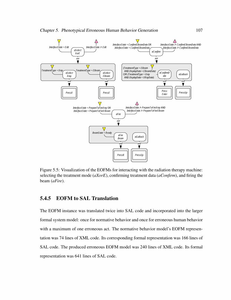
Chapter 5. Phenotypical Erroneous Human Behavior Generation 107
aSelectXorE
InterfaceState = Edit InterfaceState /= Edit
xor
aSelectXray
TreatmentType = Xray
ord
PressX
aSelectEBeam
TreatmentType = EBeam
ord
PressE
aFire
InterfaceState = PrepareToFireXray ORInterfaceState = PrepareToFireEBeam
InterfaceState /= PrepareToFireXray ANDInterfaceState /= PrepareToFireEBeam
xor
aFireBeam
BeamState = Ready
ord
PressB
aGoBack
ord
PressUp
InterfaceState = ConfirmEBeamData ORInterfaceState = ConfirmEBeamData
InterfaceState /= ConfirmEBeamData ANDInterfaceState /= ConfirmEBeamData
xor
aConfirmData
ord
PressEnter
aGoBack
ord
PressUp
(TreatmentType = EBeam AND DisplayData = EBeamData)
OR (TreatmentType = Xray AND DisplayData = XRayData)
aConfirm
Figure 5.5: Visualization of the EOFMs for interacting with the radiation therapy machine:selecting the treatment mode (aXorE), confirming treatment data (aConfirm), and firing thebeam (aFire).
5.4.5 EOFM to SAL Translation
The EOFM instance was translated twice into SAL code and incorporated into the larger
formal system model: once for normative behavior and once for erroneous human behavior
with a maximum of one erroneous act. The normative behavior model’s EOFM represen-
tation was 74 lines of XML code. Its corresponding formal representation was 166 lines of
SAL code. The produced erroneous EOFM model was 240 lines of XML code. Its formal
representation was 641 lines of SAL code.
Chapter 5. Phenotypical Erroneous Human Behavior Generation 108
5.4.6 Specification and Verification
We specify that we never want the radiation therapy machine to irradiate a patient by ad-
ministering an unshielded xray treatment using Linear Temporal Logic as follows:
G¬
BeamFireState = Fired
∧ BeamLevel = XRayPowerLevel
∧ Spreader = OutOfPlace
(5.1)
When checked against the formal system model with the translated normative task
behavior model, it verified to true in less than one second having visited 1648 states.
The formal system model containing the erroneous human behavior model produced a
counterexample after 38 seconds illustrating the following failure sequence:
1. The model initialized with the interface in the edit state with no displayed data and
the beam not ready; the beam power level not set; the spreader out of place; the beam
fire state waiting; and the human mission indicating that the human operator should
administer electron beam treatment.
2. When attempting to select the electron beam mode, the practitioner erroneously
pressed ‘X’ instead of ‘E’ (via a generated Commission activity in aSelectXorE from
Figure 5.5). This caused the interface to transition to the xray data confirmation state
and display the xray treatment data. The spreader was also moved in place and the
beam was set to the xray power level.
3. Because the incorrect data was displayed, the practitioner pressed up to return the
interface to the edit mode.
4. The practitioner selected electron beam treatment mode by pressing the ‘E’ key. The
interface transitions to the electron beam data confirmation state and displayed the
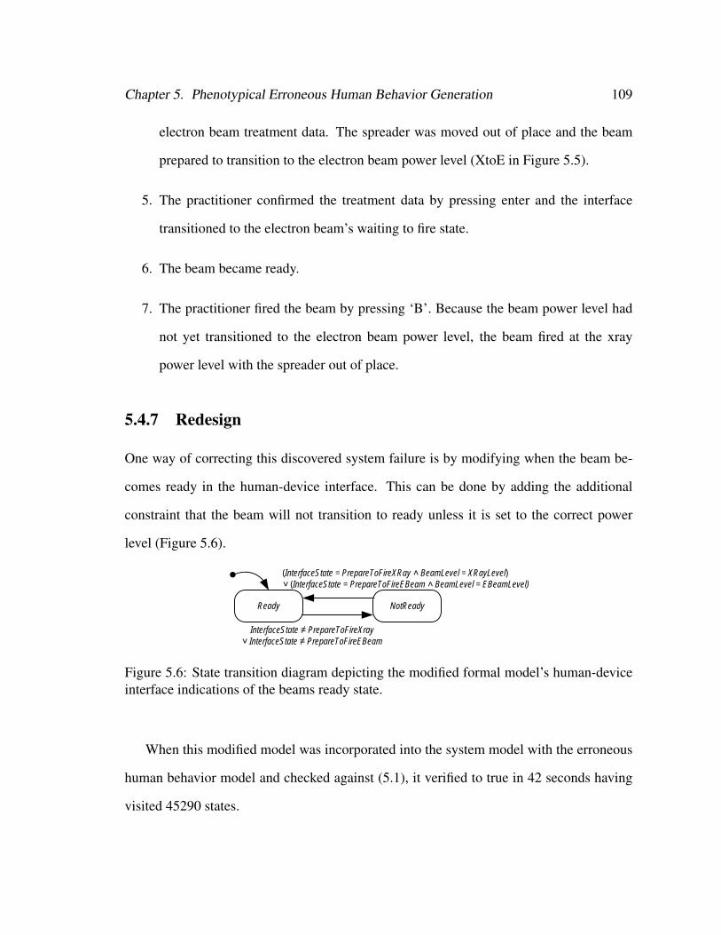
Chapter 5. Phenotypical Erroneous Human Behavior Generation 109
electron beam treatment data. The spreader was moved out of place and the beam
prepared to transition to the electron beam power level (XtoE in Figure 5.5).
5. The practitioner confirmed the treatment data by pressing enter and the interface
transitioned to the electron beam’s waiting to fire state.
6. The beam became ready.
7. The practitioner fired the beam by pressing ‘B’. Because the beam power level had
not yet transitioned to the electron beam power level, the beam fired at the xray
power level with the spreader out of place.
5.4.7 Redesign
One way of correcting this discovered system failure is by modifying when the beam be-
comes ready in the human-device interface. This can be done by adding the additional
constraint that the beam will not transition to ready unless it is set to the correct power
level (Figure 5.6).
Ready NotReady
InterfaceState ≠ PrepareToFireXray˅ InterfaceState ≠ PrepareToFireEBeam
(InterfaceState = PrepareToFireXRay ˄ BeamLevel = XRayLevel)˅ (InterfaceState = PrepareToFireEBeam ˄ BeamLevel = EBeamLevel)
Figure 5.6: State transition diagram depicting the modified formal model’s human-deviceinterface indications of the beams ready state.
When this modified model was incorporated into the system model with the erroneous
human behavior model and checked against (5.1), it verified to true in 42 seconds having
visited 45290 states.
Chapter 5. Phenotypical Erroneous Human Behavior Generation 110
5.5 Discussion
The generation process meets all of its requirements, allowing it to be integrated into our
method for the formal verification of human-automation interaction:
1. Using an EOFM task structure to replace every action in an instantiated EOFM, we
are capable of generating zero-order phenotypes of erroneous human action: omit-
ting an action, skipping an action, re-performing a previously completed action, re-
peating the last performed action, or intruding an action.
2. The use of the structure in each action, and the use of the or_seq decomposition
operator (which allows one or more sub-activities to execute) in the error generation
structure allow multiple zero-order phenotypical erroneous acts to generate all of
Hollnagel’s first-order phenotypes except for time compression.
3. The number of possible erroneous act is constrained by a maximum and a counter
preventing generated errors from making the task behavior model unbounded.
4. The erroneous behavior generation structure is represented in EOFM constructs and
is thus compatible with the EOFM to SAL translator and counterexample visualizer.
The radiation therapy machine example illustrates how this process can be used to
find potential system problems due to erroneous human behavior in human-automation
interactive systems. In fact, the discovered problem is very similar to one discovered in the
Therac-25 radiation therapy machine which resulted in the death of several people [130].
Similar problems have also resulted in injury and death with a number of modern radiation
therapy machines [24].
Chapter 5. Phenotypical Erroneous Human Behavior Generation 111
5.5.1 Statespace Complexity Optimization
The fact that the complexity of the model increases exponentially with the maximum al-
lowable number of erroneous acts indicates that analysts will be limited in the number of
erroneous acts they can introduce in a formal verification.
This is seen in the radiation therapy application in the increase in state space from
the system model with normative behavior (1648 states) to the system model with the
erroneous human behavior (45290 states) which had 27 times the number of states. For
comparison, a system model with an unconstrained human operator had 4400 states, more
than the model with normative model, but significantly less than that used by the erroneous
human behavior model. All of this suggest that future work should investigate ways to
increase the efficiency of the erroneous human behavior model.
In the current implementation there are situations where non-erroneous acts are counted
as erroneous. For example, the correct action could be executed through a Commission ac-
tivity without the CorrectAction activity executing. Similarly, the current structure allows
for the same erroneous acts to be performed in multiple ways. For example, the same
erroneous act could be performed through different Commission activities. The structure
and translation process used to generate erroneous human behavior should be optimized to
reduce redundancy and the size of the formal system model.
Given that an unconstrained human operator should theoretically support many more
action sequences than an erroneous human behavior model with a maximum of one er-
roneous act. This would suggest that the intermediary transitions in the implementation
of the SAL version of an instantiated EOFM are adding significantly to the complexity to
the model. As was discussed in [33] and Chapter 4, it may be possible to eliminate many
of the intermediary transitions and variables associated with an instantiated EOFM’s SAL
representation. Future work should investigate whether these types of improvements will
Chapter 5. Phenotypical Erroneous Human Behavior Generation 112
substantially reduce model complexity.
Although the erroneous human behavior model has the distinct disadvantage of pro-
ducing a more complex formal system model than the unconstrained one, it is important
to note that it is still useful in that it provides insights that an unconstrained model does
not. For example, the erroneous human behavior model gives analysts context for when
an error may occur for a given task, which may suggest particular solutions to discovered
problems specifically related to the human-device interface or the human task. Further, the
erroneous human behavior model allows analysts to check certain properties that could not
be checked with an unconstrained model. For the radiation therapy example, consider a
specification asserting that the practitioner will always administer treatment in the mission
specified mode. A system model containing erroneous human behavior could verify this
for up to the specified maximum number of allowable erroneous acts. However, an uncon-
strained model could not. Future work should investigate what the tradeoffs are between
the use of these two types of models.
5.5.2 Excluding Specific Erroneous Behaviors
Given the nature of formal verification with model checking and the fact that the error
generation process is done automatically, it is conceivable that an analyst will receive a
counterexample illustrating a system problem involving an erroneous human behavior that
he is not interested in or that can not be corrected. In this situation, the analyst may wish
to rerun the analysis without considering a specific erroneous behavior.
In the current implementation this can be achieved by modifying the specification to
ensure that the unwanted behavior is never executed. This can be accomplished with the
following specification:
(G(ErroneousAct = Ready))⇒ (OriginalSpecification) (5.2)
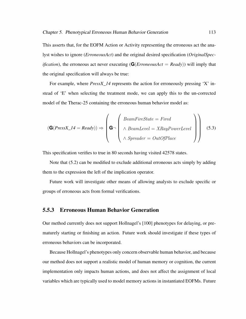
Chapter 5. Phenotypical Erroneous Human Behavior Generation 113
This asserts that, for the EOFM Action or Activity representing the erroneous act the ana-
lyst wishes to ignore (ErroneousAct) and the original desired specification (OriginalSpec-
ification), the erroneous act never executing (G(ErroneousAct = Ready)) will imply that
the original specification will always be true:
For example, where PressX_14 represents the action for erroneously pressing ‘X’ in-
stead of ‘E’ when selecting the treatment mode, we can apply this to the un-corrected
model of the Therac-25 containing the erroneous human behavior model as:
(G(PressX_14 = Ready))⇒
G¬
BeamFireState = Fired
∧ BeamLevel = XRayPowerLevel
∧ Spreader = OutOfPlace
(5.3)
This specification verifies to true in 80 seconds having visited 42578 states.
Note that (5.2) can be modified to exclude additional erroneous acts simply by adding
them to the expression the left of the implication operator.
Future work will investigate other means of allowing analysts to exclude specific or
groups of erroneous acts from formal verifications.
5.5.3 Erroneous Human Behavior Generation
Our method currently does not support Hollnagel’s [100] phenotypes for delaying, or pre-
maturely starting or finishing an action. Future work should investigate if these types of
erroneous behaviors can be incorporated.
Because Hollnagel’s phenotypes only concern observable human behavior, and because
our method does not support a realistic model of human memory or cognition, the current
implementation only impacts human actions, and does not affect the assignment of local
variables which are typically used to model memory actions in instantiated EOFMs. Future

Chapter 5. Phenotypical Erroneous Human Behavior Generation 114
work should investigate how memory errors could be incorporated into our method.
Hollnagel’s phenotypes generally assume that human behavior is executing sequen-
tially, with no parallelism or synchronization between human actions. For this reason, the
current method does not support the erroneous behavior generation for synchronized hu-
man actions (those in a sync decomposition), and does not support synchronized erroneous
actions, such as a human performing two erroneous actions synchronously or performing
the correct action synchronously with erroneous actions. Future work should investigate
how these types of erroneous acts might be incorporated.
While the process discussed here is well suited to the generation of single erroneous
actions, generating more complex erroneous behaviors requires a significant number of
erroneous acts. This would greatly increase model complexity, and treats more unlikely
action sequences equal to ones that are more cognitively probable (see [159]). Chapter 6
explores an alternative error generation process that begins to addresses this issue.
Chapter 6
Strategic Knowledge-based Erroneous
Behavior Generation
Our phenotypical erroneous human behavior generation technique (Chapter 5) is capable
of reproducing all of Hollnagel’s zero-order phenotypes that relate to the performance or
non-performance of actions. While this takes advantage of the EOFM’s task structure
representation capabilities, it does not address erroneous human behaviors that may arise
due to strategic (i.e., conditions under which activities and actions should be considered)
knowledge. Reason [159], as part of his Generic Error Modeling System, outlined a set
of erroneous behaviors called slips in which a person fails to notice conditions which re-
sult in a failure to perform an activity or action normatively due to either inattention or
overattention (attending at the inappropriate time). A person can omit an action or high
level activity by failing to notice that the necessary conditions for performing the activity
are true, possibly due to interruption or not attending to information at the right time. A
person may erroneously repeat an action or high level activity after losing his place in a
task. A person may also have his attention “captured” by something else (external or inter-
nal to the person) which results in him performing (committing) an inappropriate action or
activity either in addition to or instead of an appropriate one.
115
Chapter 6. Strategic Knowledge-based Erroneous Behavior Generation 116
From a completely observable perspective, this means that a slip can manifest as:
• An omission, the failure to perform all or part of an activity;
• A repetition, the repeated performance of an activity or action; or
• A commission, the inappropriate performance of an activity or action.
Our phenotypical erroneous human behavior generation process is particularly well
suited to replicating single action slips as it is fully capable of generating omissions, repe-
titions, and other commissions for single atomic actions, and two or more of these can be
chained together to form more complex erroneous behavior. However, replicating these at
an activity level of abstraction would require a maximum number of erroneous acts large
enough to support the chaining of multiple zero-order phenotypes to replicate the correct
execution of activities in an erroneous context. This approach would significantly increase
the complexity of the model (see Section 5.3) and it would introduce a number or erroneous
action sequences beyond those associated with the above cognitive justifications.
This chapter discusses how the strategic knowledge represented in EOFM conditions
can be manipulated to generate Reason’s [159] slips at the activity level. We validate our
implementation of the process. We also benchmark the process in order to evaluate how
the incorporations of erroneous behavior can impact model complexity. The PCA pump
example from [31] (Chapter 3) is revisited, and we show how this new erroneous behavior
generation process can be used to discover a previously unseen system failure using our
method. We show how the human-device interface could potentially be modified to prevent
the discovered failure from occurring.
Chapter 6. Strategic Knowledge-based Erroneous Behavior Generation 117
6.1 Automatic Strategic Knowledge-based Erroneous
Human Behavior Generation
This erroneous human behavior generation process should be capable of replicating the
manifestation of Reason’s [159] slips for omitting, repeating, or committing activities or
actions based on misapplication of EOFM strategic knowledge contained in pre, repeat,
and completion conditions. Because an unbounded number of erroneous acts could result
in an unbounded human task behavior model, the error generation process must support
a mechanism for constraining the number of erroneous acts that can be performed in the
formally translated erroneous human behavior model. In order to facilitate analysis, the
EOFM to SAL translation process, and counterexample interpretation, the error structure
should be compatible with the EOFM language and translator.
These strategic knowledge-based erroneous behaviors were incorporated into translated
EOFM task representations by making changes to the formal semantics (Figure 6.1). In this
design, addition transitions (dotted arrows in Figure 6.1) are added to the formal semantics
in order to describe erroneous conditions in which an activity can switch between execution
states. This design includes an upper bound on the number of erroneous acts (KMax) and
a variable (KCount) that keeps track of the number of erroneous acts that a task model
has performed. An erroneous transition can only be undertaken if the current number
of erroneous transitions is less than the maximum (KCount < KMax). Every time an
erroneous transition occurs, KCount is incremented by one (KCount++).
Each new transition represents the erroneousness analog of a non-erroneous transi-
tion, where the erroneous transition is conditioned on the same start or end condition as
its analog as well as the negation of any strategic knowledge (pre, completion, or repeat
condition) used by any non-erroneous transition.
Omissions can occur when an activity completes its execution too early. An activity can
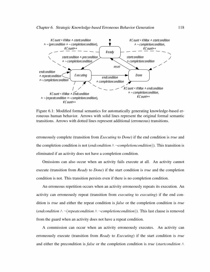
Chapter 6. Strategic Knowledge-based Erroneous Behavior Generation 118
Ready
Executingendcondition ˄ repeatcondition˄¬ completioncondition
startcondition ˄ precondition˄ ¬ completioncondition
endcondition˄ completioncondition
startcondition ˄ completioncondition
Done
reset
KCount < KMax ˄ startcondition ˄ ¬ (precondition ˄ ¬ completioncondition),
KCount++
KCount < KMax ˄ startcondition ˄ ¬ completioncondition,
KCount++
KCount < KMax ˄ endcondition ˄ ¬ completioncondition,
KCount++KCount < KMax ˄ endcondition
˄ ¬ (repeatcondition ˄¬ completioncondition),KCount++
Figure 6.1: Modified formal semantics for automatically generating knowledge-based er-roneous human behavior. Arrows with solid lines represent the original formal semantictransitions. Arrows with dotted lines represent additional (erroneous) transitions.
erroneously complete (transition from Executing to Done) if the end condition is true and
the completion condition is not (endcondition∧¬completioncondition)). This transition is
eliminated if an activity does not have a completion condition.
Omissions can also occur when an activity fails execute at all. An activity cannot
execute (transition from Ready to Done) if the start condition is true and the completion
condition is not. This transition persists even if there is no completion condition.
An erroneous repetition occurs when an activity erroneously repeats its execution. An
activity can erroneously repeat (transition from executing to executing) if the end con-
dition is true and either the repeat condition is false or the completion condition is true
(endcondition ∧ ¬(repeatcondition ∧ ¬completioncondition)). This last clause is removed
from the guard when an activity does not have a repeat condition.
A commission can occur when an activity erroneously executes. An activity can
erroneously execute (transition from Ready to Executing) if the start condition is true
and either the precondition is false or the completion condition is true (startcondition ∧
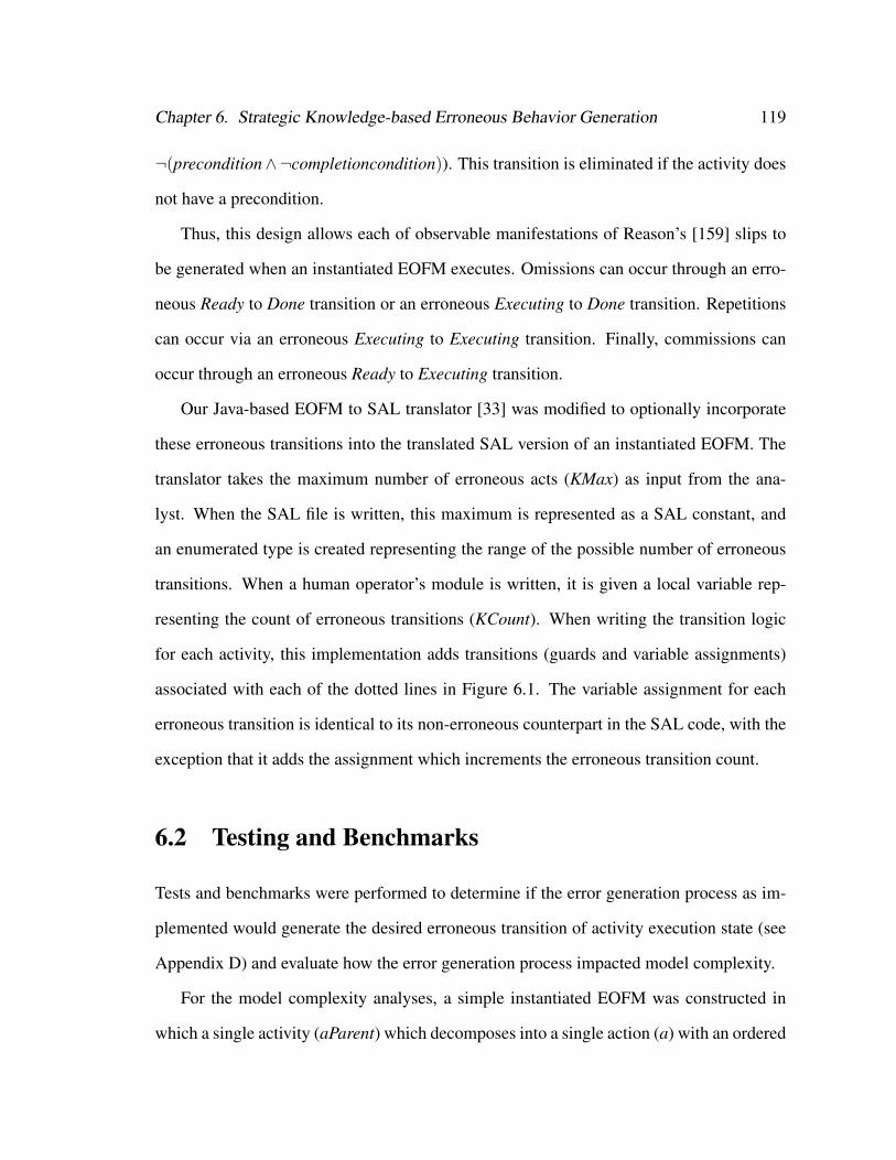
Chapter 6. Strategic Knowledge-based Erroneous Behavior Generation 119
¬(precondition∧¬completioncondition)). This transition is eliminated if the activity does
not have a precondition.
Thus, this design allows each of observable manifestations of Reason’s [159] slips to
be generated when an instantiated EOFM executes. Omissions can occur through an erro-
neous Ready to Done transition or an erroneous Executing to Done transition. Repetitions
can occur via an erroneous Executing to Executing transition. Finally, commissions can
occur through an erroneous Ready to Executing transition.
Our Java-based EOFM to SAL translator [33] was modified to optionally incorporate
these erroneous transitions into the translated SAL version of an instantiated EOFM. The
translator takes the maximum number of erroneous acts (KMax) as input from the ana-
lyst. When the SAL file is written, this maximum is represented as a SAL constant, and
an enumerated type is created representing the range of the possible number of erroneous
transitions. When a human operator’s module is written, it is given a local variable rep-
resenting the count of erroneous transitions (KCount). When writing the transition logic
for each activity, this implementation adds transitions (guards and variable assignments)
associated with each of the dotted lines in Figure 6.1. The variable assignment for each
erroneous transition is identical to its non-erroneous counterpart in the SAL code, with the
exception that it adds the assignment which increments the erroneous transition count.
6.2 Testing and Benchmarks
Tests and benchmarks were performed to determine if the error generation process as im-
plemented would generate the desired erroneous transition of activity execution state (see
Appendix D) and evaluate how the error generation process impacted model complexity.
For the model complexity analyses, a simple instantiated EOFM was constructed in
which a single activity (aParent) which decomposes into a single action (a) with an ordered
Chapter 6. Strategic Knowledge-based Erroneous Behavior Generation 120
(ord) decomposition operator. This translated EOFM interacts with a simple human-device
interface model which can receive all human operator actions. The human operator also
receives Boolean inputs (precondition, repeatcondition, and completioncondition) from the
human-device interface model which give (aParent) access to simulated pre, repeat, and
completion conditions that can change between true and false (or remain unchanged) at
each step in a system model’s execution. Because model complexity should vary based
on the maximum number of erroneous transitions (KMax), this was varied in these tests
in order to obtain metrics of complexity (number of states) and verification time. Using
SAL’s symbolic model checker (SAL-SMC) on a dual core 2.8 gigahertz machine with 16
gigabytes of RAM running Ubuntu Linux, we ran 5 trials (with a maximum of between 0
and 4 erroneous transition). The results are reported in Figure 6.2.
# States Verification Time (s)0 46 0.1 0.1 461 208 0.12 0.12 2082 394 0.14 0.14 3943 586 0.15 0.15 5864 778 0.16 0.16 778
400
500
600
700
800
900
0.08
0.1
0.12
0.14
0.16
0.18
# St
ates
atio
n Ti
me
(s)
0
100
200
300
400
500
600
700
800
900
0
0.02
0.04
0.06
0.08
0.1
0.12
0.14
0.16
0.18
0 1 2 3 4
# St
ates
Verif
icat
ion
Tim
e (s
)
# Maximum Erroneous Transitions
Verification Time (s)
# States
Verification# States0 0.1 46
0
100
200
300
400
500
600
700
800
900
0
0.02
0.04
0.06
0.08
0.1
0.12
0.14
0.16
0.18
0 1 2 3 4
# St
ates
Verif
icat
ion
Tim
e (s
)
# Maximum Erroneous Transitions
Verification Time (s)
# States
0 0.1 461 0.12 2082 0.14 3943 0.15 5864 0.16 778
0
100
200
300
400
500
600
700
800
900
0
0.02
0.04
0.06
0.08
0.1
0.12
0.14
0.16
0.18
0 1 2 3 4
# St
ates
Verif
icat
ion
Tim
e (s
)
# Maximum Erroneous Transitions
Verification Time (s)
# States
0.18900
0
100
200
300
400
500
600
700
800
900
0
0.02
0.04
0.06
0.08
0.1
0.12
0.14
0.16
0.18
0 1 2 3 4
# St
ates
Verif
icat
ion
Tim
e (s
)
# Maximum Erroneous Transitions
Verification Time (s)
# States
0.06
0.08
0.1
0.12
0.14
0.16
0.18
300
400
500
600
700
800
900
Verif
icat
ion
Tim
e (s
)
# St
ates
0
100
200
300
400
500
600
700
800
900
0
0.02
0.04
0.06
0.08
0.1
0.12
0.14
0.16
0.18
0 1 2 3 4
# St
ates
Verif
icat
ion
Tim
e (s
)
# Maximum Erroneous Transitions
Verification Time (s)
# States
0
0.02
0.04
0.06
0.08
0.1
0.12
0.14
0.16
0.18
0
100
200
300
400
500
600
700
800
900
0 1 2 3 4
Verif
icat
ion
Tim
e (s
)
# St
ates
# Maximum Erroneous Transitions
# States
Verification Time (s)
Figure 6.2: Plot of the maximum number of erroneous transitions vs. the number of systemmodel states and transition time.
These results indicate that both the size of the statespace and the verification time in-
crease linearly with the number of erroneous transitions.
Chapter 6. Strategic Knowledge-based Erroneous Behavior Generation 121
6.3 Application
To demonstrate how this type of error generation can be used, we revisit the simplified
Patient Controlled Analgesia (PCA) Pump example produced in Phase 2 of the modeling
effort discussed in [31] and Chapter 3.
6.3.1 Formal Modeling
All of the formal models were constructed using the Symbolic Analysis Laboratory (SAL)
language [65]. Formal models of the mission were represented as a set of viable prescrip-
tion options (realistic PCA dosages and delays). The mission (prescription), human task,
human-device interface, and device automation were independently modeled. Because the
PCA pump generally operates in a controlled environment, no environmental model was
included. Because of the limited available pump documentation, the system automation
model was restricted to pump programming procedures. For more information about this
modeling process, model granularity, and the rationale behind the modeling decisions see
[27, 31] and/or Chapter 3. Note that because this particular application was not concerned
with how a practitioner programs a specific prescription into the pump, but the circum-
stances under which he may make an error, this version of the model was modified slightly
to decrease its complexity with only a subset of prescription options placeholding for more
realistic ones. PCA doses were restricted to between 1 and 10 ml (in 1 ml increments) and
delays were restricted to be within 1 and 20 minutes (in 1 minute increments). The human
mission was also restricted to allowable PCA doses of 5 and 10 ml and prescribed delays
of 10 and 20 minutes.
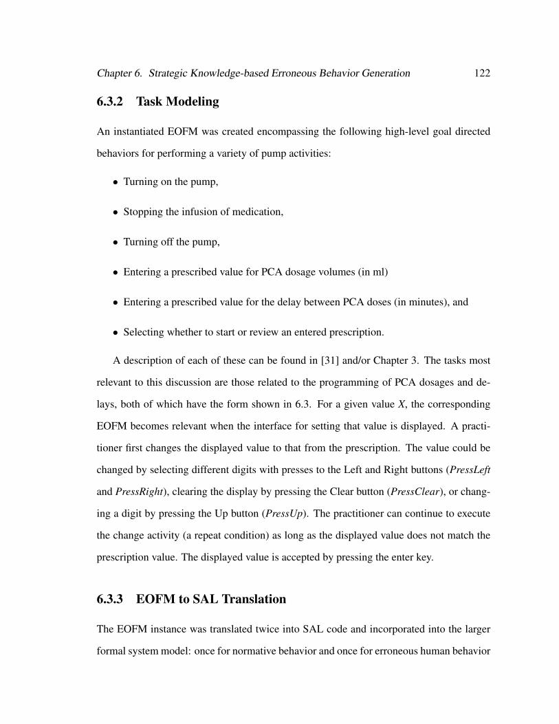
Chapter 6. Strategic Knowledge-based Erroneous Behavior Generation 122
6.3.2 Task Modeling
An instantiated EOFM was created encompassing the following high-level goal directed
behaviors for performing a variety of pump activities:
• Turning on the pump,
• Stopping the infusion of medication,
• Turning off the pump,
• Entering a prescribed value for PCA dosage volumes (in ml)
• Entering a prescribed value for the delay between PCA doses (in minutes), and
• Selecting whether to start or review an entered prescription.
A description of each of these can be found in [31] and/or Chapter 3. The tasks most
relevant to this discussion are those related to the programming of PCA dosages and de-
lays, both of which have the form shown in 6.3. For a given value X, the corresponding
EOFM becomes relevant when the interface for setting that value is displayed. A practi-
tioner first changes the displayed value to that from the prescription. The value could be
changed by selecting different digits with presses to the Left and Right buttons (PressLeft
and PressRight), clearing the display by pressing the Clear button (PressClear), or chang-
ing a digit by pressing the Up button (PressUp). The practitioner can continue to execute
the change activity (a repeat condition) as long as the displayed value does not match the
prescription value. The displayed value is accepted by pressing the enter key.
6.3.3 EOFM to SAL Translation
The EOFM instance was translated twice into SAL code and incorporated into the larger
formal system model: once for normative behavior and once for erroneous human behavior
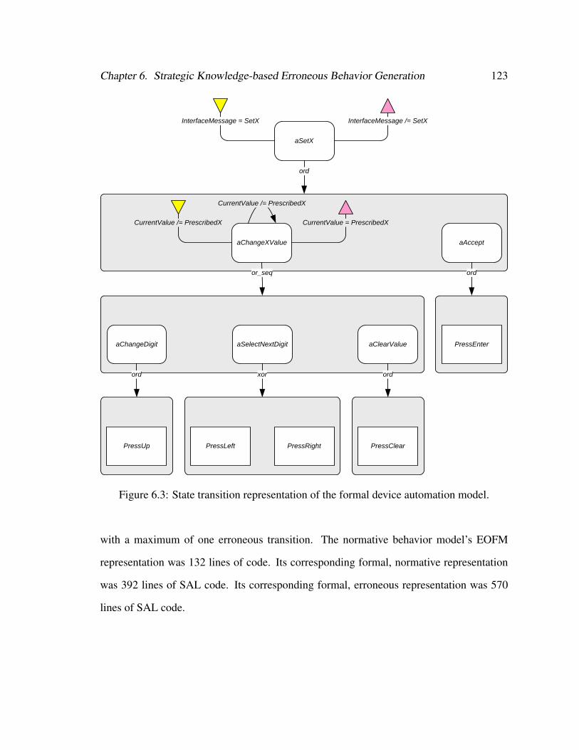
Chapter 6. Strategic Knowledge-based Erroneous Behavior Generation 123
aSetX
InterfaceMessage = SetX InterfaceMessage /= SetX
ord
aChangeXValue
CurrentValue /= PrescribedX
CurrentValue /= PrescribedX
CurrentValue = PrescribedX
or_seq
aChangeDigit
ord
PressUp
aSelectNextDigit
xor
PressLeft PressRight
aClearValue
ord
PressClear
aAccept
ord
PressEnter
Figure 6.3: State transition representation of the formal device automation model.
with a maximum of one erroneous transition. The normative behavior model’s EOFM
representation was 132 lines of code. Its corresponding formal, normative representation
was 392 lines of SAL code. Its corresponding formal, erroneous representation was 570
lines of SAL code.
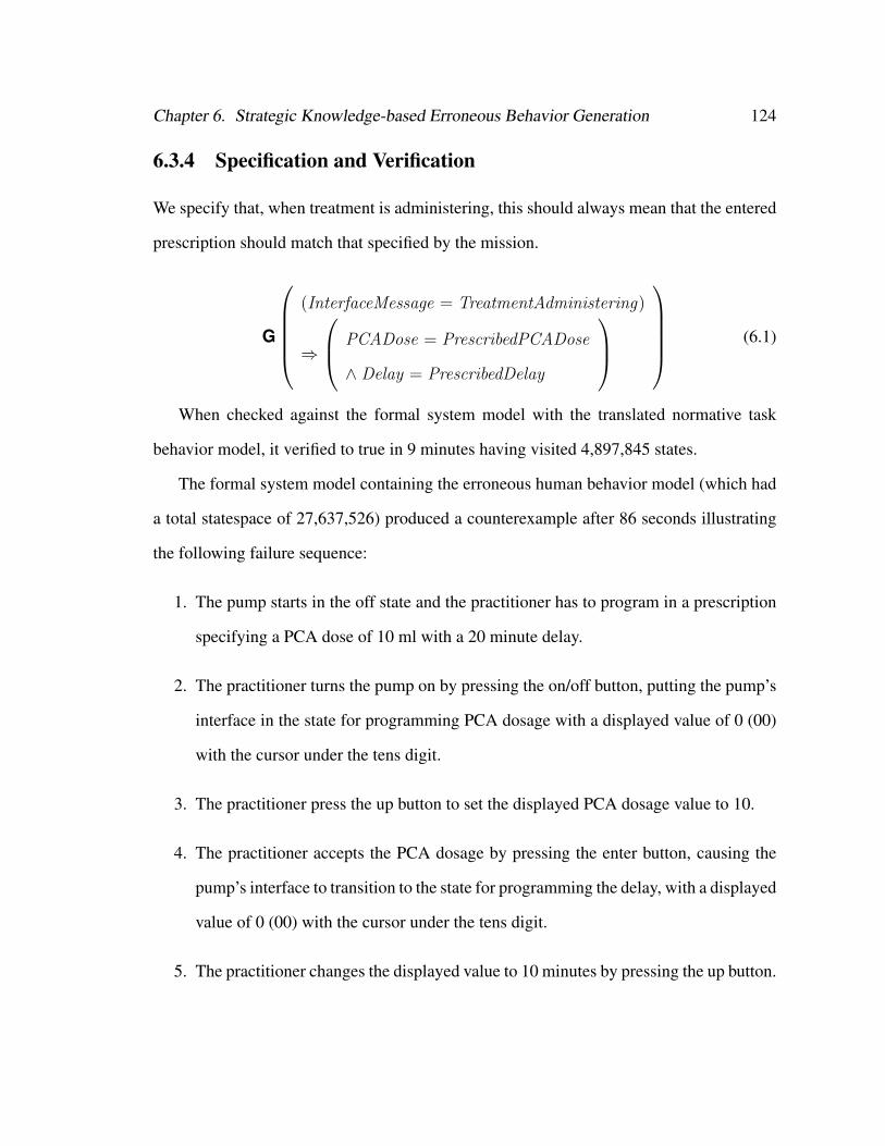
Chapter 6. Strategic Knowledge-based Erroneous Behavior Generation 124
6.3.4 Specification and Verification
We specify that, when treatment is administering, this should always mean that the entered
prescription should match that specified by the mission.
G
(InterfaceMessage = TreatmentAdministering)
⇒
PCADose = PrescribedPCADose
∧ Delay = PrescribedDelay
(6.1)
When checked against the formal system model with the translated normative task
behavior model, it verified to true in 9 minutes having visited 4,897,845 states.
The formal system model containing the erroneous human behavior model (which had
a total statespace of 27,637,526) produced a counterexample after 86 seconds illustrating
the following failure sequence:
1. The pump starts in the off state and the practitioner has to program in a prescription
specifying a PCA dose of 10 ml with a 20 minute delay.
2. The practitioner turns the pump on by pressing the on/off button, putting the pump’s
interface in the state for programming PCA dosage with a displayed value of 0 (00)
with the cursor under the tens digit.
3. The practitioner press the up button to set the displayed PCA dosage value to 10.
4. The practitioner accepts the PCA dosage by pressing the enter button, causing the
pump’s interface to transition to the state for programming the delay, with a displayed
value of 0 (00) with the cursor under the tens digit.
5. The practitioner changes the displayed value to 10 minutes by pressing the up button.

Chapter 6. Strategic Knowledge-based Erroneous Behavior Generation 125
6. The practitioner erroneously completed the activity for changing the displayed value
(the erroneous Executing to Done transition) and presses enter to accept a delay
value of 10 minutes. The pump transitions to the interface state for starting or review
treatment.
7. The practitioner starts treatment by pressing the start button, causing treatment to
administer with the pump interface in the TreatmentAdministering state. Thus, the
specification has been violated with the pump administering treatment with an un-
prescribed delay value.
6.3.5 Redesign
We can use our method to investigate potential design changes that correct the discovered
problem. One possible way of preventing this problem from occurring is to force the prac-
titioner to review the entered prescription every time it changes. This can be accomplished
by having the pump keep track of whether or not the practitioner has reviewed the entered
prescription or not, and only letting him start the administration of treatment after an en-
tered or changed prescription has been reviewed. This change was made to the PCA pump
model, and the resulting model was verified against 6.1 with the erroneous human behavior
model from above. This time, the specification verified to true in 51 minutes having visited
210,249,809 states.
6.4 Discussion
The erroneous behavior generation process presented here provides an additional means of
allowing practitioners to automatically determine when potentially unexpected erroneous
behavior can result in a violation of a systems safety properties. Further, the generation
Chapter 6. Strategic Knowledge-based Erroneous Behavior Generation 126
process meets all of its requirements, allowing it to be integrated into our method for the
formal verification of human-automation interaction:
1. By adding erroneous transitions to the formal semantics of an EOFM’s activity exe-
cution state representing erroneous applications of strategic knowledge (pre, repeat,
and completion conditions), we are capable of replicating the observable manifesta-
tion of attentional failures associated with Reason’s [159] slips: omission, repetition,
or commission (due to capture).
2. The number of possible erroneous transitions is constrained by a maximum and a
counter preventing generated erroneous behaviors from making the task behavior
model unbounded.
3. The erroneous behavior generation does not alter the structure of the EOFM and is
thus compatible with the EOFM to SAL translator and counterexample visualizer.
6.4.1 Tradeoff Between Erroneous Behavior Generation Techniques
In terms of complexity, the error generation process presented here represents an alterna-
tive to the method presented in Chapter 5, where model complexity increases linearly with
the number of allowable erroneous behaviors rather than exponentially. This is further
reinforced by the fact that, for the presented application, the system model with an erro-
neous human behavior model with a maximum of one erroneous transition had a smaller
statespace than a system model with an unconstrained human operator (27,637,526 vs
126,617,856 states), a condition not achieved using the techniques from Chapter 5.
The two generation techniques produce different erroneous behaviors. The techniques
discussed here can generate higher level erroneous behaviors based on the incorrect execu-
tion of activities where as the method discussed in Chapter 5 can be used to generate lower
Chapter 6. Strategic Knowledge-based Erroneous Behavior Generation 127
level erroneous acts, and can allow for the modeling of many more extraneous behaviors
as it is capable of generating erroneous actions that are not associated with the currently
executing activity. Because of this, analysts may wish to evaluate a system using both
techniques either in separation or together in order to obtain the most complete system
evaluation.
6.4.2 Excluding Specific Erroneous Behaviors
As with the other erroneous human behavior generation method, it is conceivable that an
analyst using this method will receive a counterexample illustrating a system problem in-
volving an erroneous human behavior that he is not interested in or that cannot be corrected
through a cost effective design intervention. In this situation, the analyst may wish to rerun
the analysis without considering a specific erroneous behavior.
The analyst can accomplish this by manually editing the erroneous human behavior
model to remove the undesired erroneous transition. Given the way EOFM formal seman-
tics are implemented in SAL, each erroneous transition is represented by a single guard
(the condition on the transition) and a set of assignments under the guard. Thus, to remove
any given erroneous transition, an analyst need only delete or comment out the associated
guard and assignments. This procedure is used as part of an evaluation documented in
Chapter 8.
Future work should investigate other means of allowing analysts to exclude specific or
groups of erroneous transitions from formal verifications without the need to modify the
formal model’s code.
Chapter 6. Strategic Knowledge-based Erroneous Behavior Generation 128
6.4.3 Error Generation
The erroneous behavior generation process discussed here is only capable of replicating
capture slips for activities in a particular peer group: either within a given decomposition,
or all parent level activities. However, capture slips can also manifest as a human operator
perform all or part of a completely unrelated activity, especially if the activities occur under
similar circumstances or are are composed of similar sequences of behavior [159]. Future
work should investigate how such slips could be incorporated into our erroneous behavior
generation process.
Reason’s GEMS [159] classifies erroneous behaviors beyond the slip designations that
have been discussed here. Specifically, slips only relate to erroneous behaviors that occur
as a result of attentional failures which result in operators incorrectly performing tasks that
they know how to perform correctly. A different class of erroneous behaviors, mistakes,
occur when the human operator intentionally performs an erroneous behavior because he
does not know how to perform a task correctly. This can occur either because of rule-
based or knowledge-based failures. Rule based mistakes occur when the human performs
a valid rule or schema for achieving a goal in an incorrect place or performs an invalid rule.
Failures at the knowledge level occur when the operator has incorrect knowledge about the
domain or environment. Future work should investigate how cognitive modeling could be
paired with our method in order to generate mistakes.
The work of Blandford, Curzon, and Rukše et al. [61, 62, 160, 161] have used cogni-
tive modeling to produce erroneous human behaviors in verifications of models containing
human-automation interaction. Doing this, they can generate erroneous behaviors related
to the repetition of actions, the omission of actions, the commission of correct actions in
the wrong context, the replacement of one action with another, the performance one or
more actions out of order, and the performance of unrelated actions; all of which can oc-
Chapter 6. Strategic Knowledge-based Erroneous Behavior Generation 129
cur for a variety cognitive reasons. Even though we only model human task behavior, our
two error generation techniques are capable of generating all of these erroneous behaviors
without the need for detailed cognitive modeling. Thus, the use of human task behavior
modeling with formal verification is similarly powerful to the cognitive modeling work in
in terms of its ability to evaluate the impact of erroneous human behavior on system safety
properties.
Chapter 7
Counterexample Visualization∗
Using our method, instantiated EOFM task models are translated into the language of the
Symbolic Analysis Laboratory (SAL) [65] using the language’s formal semantics [33].
Formal verifications are performed on the complete system model. Each step in a SAL
produced counterexample is presented as a list of variable values sorted by variable name,
with no indication of the relationships between variables. Further, the translation process
divorces the formal representation of the human task behavior from its original EOFM
instantiation. This chapter reviews the literature on counterexample visualization and syn-
thesizes concepts from existing techniques to show how the human-automation interaction
architectural framework and the visual notation supported by the EOFM can be used to cre-
ate a counterexample visualization to help analysts evaluate the role of human-automation
interaction in specification violations.
7.1 Counterexample Visualization Techniques
A variety of tools and techniques have attempted to display counterexamples in ways that
are more useful than the standard output. These include variable tables; state diagrams;
∗This chapter is derived from [30]
130
Chapter 7. Counterexample Visualization 131
process and sequence diagrams; and domain or application dependent representations.
7.1.1 Variable Tables
Tables are typically used to depict variable values in each step in the counterexample,
allowing variable values to be easily compared between steps. Table representations are
supported by some model checkers such as the Cadence SMV [137]. These tables can also
be enhanced to make it easier to compare variable values between steps by highlighting
changes [49, 133]. They can also allow analysts to hide variables and steps from the display
[120].
7.1.2 State Diagrams
A number of counterexample visualization concepts have focused on displaying the ex-
ecution path through a state diagram of the model. Tools such as UPPAAL2k [8] and
STATEMATE [92] represent models using the statecharts visual formalism [91] and allow
counterexamples to be visually inspected by highlighting states and/or transitions active at
each step.
Some tools [6, 52, 75] allow representations of a model’s state space to be interac-
tively explored to find witnesses or counterexamples. In these representations, a subset of
the systems states are depicted as nodes in a directed graph with model specified transi-
tions between them. The presented state space subset is calculated from user specifiable
proof strategies [52, 75] or statistical measures [6]. Nodes can be interactively examined
in order to get a complete view of their variable values, and the tools provide feedback
about whether temporal logic properties evaluate to true. Human analysts can expand their
search of the state space by interactively selecting paths or applying new proof strategies.
The tools facilitate this task by highlighting paths statistically likely to produce a coun-

Chapter 7. Counterexample Visualization 132
terexample [6] or label each graph edge with the proof steps used to reach the target states
[52].
7.1.3 Process and Sequence Diagrams
Process and sequence diagrams have also been used to visualize counterexamples, where
variables are either grouped together in domain relevant designations (such as processes or
threads for software) or represented by themselves [7, 8, 10, 49, 75, 104, 119, 175]. These
designations are listed along an axis with a line extending out below them along a time or
counterexample step axis. A mark (such as a dot or box) on one of these lines indicates a
change in the state of the designation’s variables at the given time or step, and can usually
be interactively inspected to access full state variable value listings. Marks connected at
a given step or time by a line or arrow can either show synchronized changes between
the designations [119] or that one designation is passing information to another [10]. The
lines extending from designations can be highlighted with different colors to convey the
truth value of temporal logic properties [119, 175].
7.1.4 Domain and Application Dependent Representations
Several visualization techniques translate counterexample data into representations specific
to a particular domain or application such as timing plots for models of computer hardware
[109, 177]. Models animating human interaction with visual prototypes of human-device
interfaces for counterexamples and formal model simulation traces have also been explored
[3, 49].
7.1.5 Common Features
These visualization share common features that support evaluation including:
Chapter 7. Counterexample Visualization 133
1. Encapsulation of variables or states: The sequence diagrams and application de-
pendent representations allow model state variables to be encapsulated in higher level
designations that are familiar to the analyst. These also sort model variables and re-
move visual clutter.
2. Interactive detail refinement: By allowing analysts to interactively query for infor-
mation not currently displayed, visualizations support encapsulation without remov-
ing access to detailed information.
3. Highlighting analysis relevant changes: The discussed representations visually
emphasize changes in model variables at several levels: individual variables; des-
ignations; and system properties specified in temporal logic. Tables, sequence dia-
grams, and state diagram animations highlight changes in individual variables. Se-
quence diagrams and tables show coordination between changes in state between
different variables or designations. Some sequence diagram and state diagrams pro-
vide visual feedback about the value of analysis-relevant temporal logic properties.
7.2 Operational Concept and Design
An analyst performing formal verifications of human-automation interaction is interested
in determining how human behavior contributes to a violation of a system specification.
The analyst wants to examine the conditions under which the human operator performs
actions and what the impact of those actions are on the other elements of the system. To
support analysts perform such a verification using SAL, our architectural framework, and
our EOFM task modeling language; we have developed a counterexample visualization
that draws from the common features of other visualization techniques and EOFM’s visual
notation. This allows an analyst to visualize the execution state of the human task behavior
Chapter 7. Counterexample Visualization 134
at each counterexample step and compare it to information from other architectural compo-
nents while highlighting changes in model state at the individual variable and architectural
levels.
7.2.1 Encapsulation of Variables or States
The visualization encapsulates variable states based on the elements of the architectural
framework (mission, task behavior, human-device interface, device automation, environ-
ment, and other1) and EOFM’s visual notation. High level designations of these are orga-
nized in a table with designations as the rows and counterexample steps as the columns.
7.2.2 Interactive Detail Refinement
The visualization allows an analyst to interactively inspect the values of encapsulated vari-
ables. An analyst can traverse the table by either using navigation buttons (previous: J
and next: I) or by scrolling through the table cells and selecting a specific step. Selecting
a cell moves a cursor (↓) that points to the associated step’s column and presents a detailed
view of the model variable’s values in a separate, detailed view. This view presents the
individual variable values from the system model elements for the given step in separate
labeled columns. It also displays the execution state of the human task task behavior model
using EOFM’s visual notation.
The formal semantics of the EOFM language [33] specify that each activity and action
in an instantiated EOFM has three possible execution states: Ready (waiting to execute),
Executing, and Done (finished executing). When the visualizer presents the execution state
of the human operator’s task behavior model, it renders the entire graph for the goal level
(root) activity that is executing. It color codes each of the activities and actions in this
1A designation used for any variables that do not fit in the architectural designations, such as erroneousbehavior counters or handshake protocol variables.
Chapter 7. Counterexample Visualization 135
structure to indicate its execution state: white for Ready, green for Executing, and grey for
Done.
7.2.3 Highlighting Analysis Relevant Changes
The visualization highlights changes in variable values in both the high level encapsulated
designations and the individual variables. At the high level, each table cell’s color indicates
whether or not there has been a change in one of the associated designation’s variables since
the previous step: white for no change, and yellow for a change. In our architecture, human
task behavior can only produce a change in the other elements of the system architecture if a
human action is performed. Thus, a counterexample step with a human action is indicated
with an ‘X’ in its corresponding table cell. In the detailed view, variables whose values
changed from the previous step are highlighted in yellow. An activity or action whose
execution state has changed since the previous step is presented with a yellow highlight
around its border.
7.2.4 Implementation
A counterexample visualization prototype is currently implemented in Microsoft Visio and
Visual Basic for Applications. It takes an instantiated EOFM and a text file containing a
SAL produced counterexample as input. The software identifies variables within the coun-
terexample that represent the human task behavior model. It then presents the remaining
variables to the analyst who indicates under which architectural designation the remaining
variables belong: the human operator’s mission, the human-device interface, the device au-
tomation, or the operational environment. The software then renders each detailed view of
the counterexample as a separate page in a Visio document. The high-level encapsulation
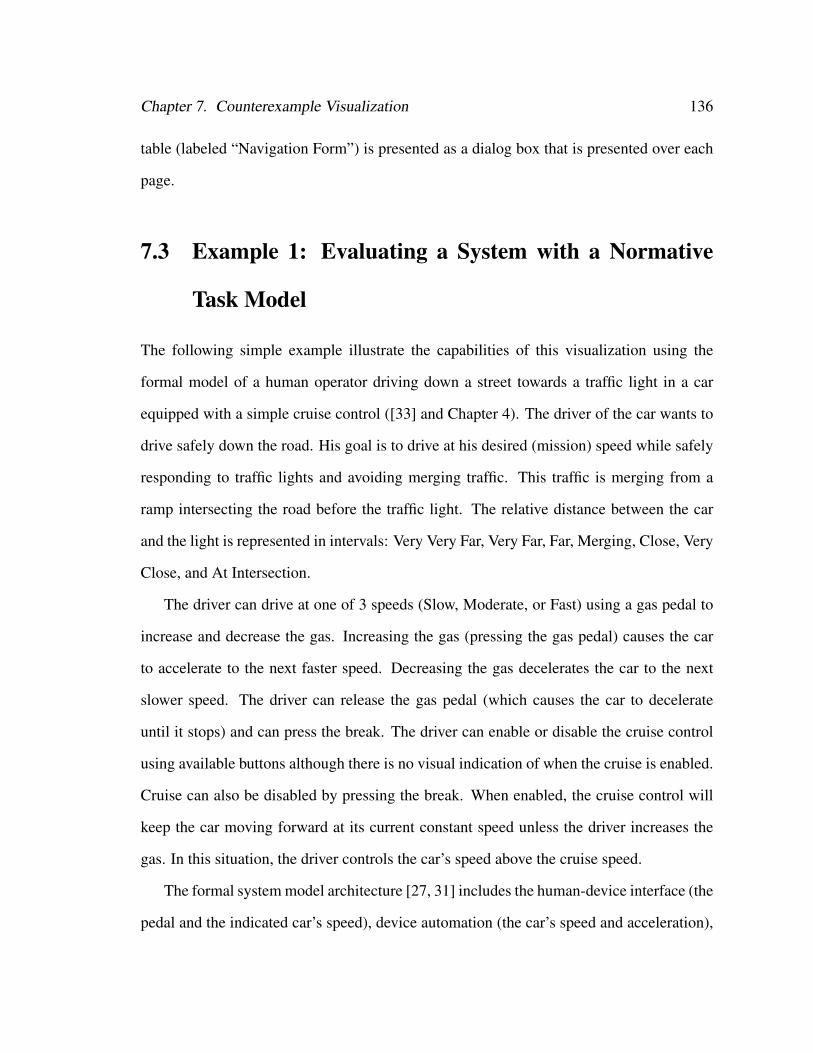
Chapter 7. Counterexample Visualization 136
table (labeled “Navigation Form”) is presented as a dialog box that is presented over each
page.
7.3 Example 1: Evaluating a System with a Normative
Task Model
The following simple example illustrate the capabilities of this visualization using the
formal model of a human operator driving down a street towards a traffic light in a car
equipped with a simple cruise control ([33] and Chapter 4). The driver of the car wants to
drive safely down the road. His goal is to drive at his desired (mission) speed while safely
responding to traffic lights and avoiding merging traffic. This traffic is merging from a
ramp intersecting the road before the traffic light. The relative distance between the car
and the light is represented in intervals: Very Very Far, Very Far, Far, Merging, Close, Very
Close, and At Intersection.
The driver can drive at one of 3 speeds (Slow, Moderate, or Fast) using a gas pedal to
increase and decrease the gas. Increasing the gas (pressing the gas pedal) causes the car
to accelerate to the next faster speed. Decreasing the gas decelerates the car to the next
slower speed. The driver can release the gas pedal (which causes the car to decelerate
until it stops) and can press the break. The driver can enable or disable the cruise control
using available buttons although there is no visual indication of when the cruise is enabled.
Cruise can also be disabled by pressing the break. When enabled, the cruise control will
keep the car moving forward at its current constant speed unless the driver increases the
gas. In this situation, the driver controls the car’s speed above the cruise speed.
The formal system model architecture [27, 31] includes the human-device interface (the
pedal and the indicated car’s speed), device automation (the car’s speed and acceleration),
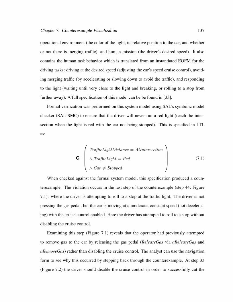
Chapter 7. Counterexample Visualization 137
operational environment (the color of the light, its relative position to the car, and whether
or not there is merging traffic), and human mission (the driver’s desired speed). It also
contains the human task behavior which is translated from an instantiated EOFM for the
driving tasks: driving at the desired speed (adjusting the car’s speed cruise control), avoid-
ing merging traffic (by accelerating or slowing down to avoid the traffic), and responding
to the light (waiting until very close to the light and breaking, or rolling to a stop from
further away). A full specification of this model can be be found in [33].
Formal verification was performed on this system model using SAL’s symbolic model
checker (SAL-SMC) to ensure that the driver will never run a red light (reach the inter-
section when the light is red with the car not being stopped). This is specified in LTL
as:
G¬
TrafficLightDistance = AtIntersection
∧ TrafficLight = Red
∧ Car 6= Stopped
(7.1)
When checked against the formal system model, this specification produced a coun-
terexample. The violation occurs in the last step of the counterexample (step 44; Figure
7.1): where the driver is attempting to roll to a stop at the traffic light. The driver is not
pressing the gas pedal, but the car is moving at a moderate, constant speed (not decelerat-
ing) with the cruise control enabled. Here the driver has attempted to roll to a stop without
disabling the cruise control.
Examining this step (Figure 7.1) reveals that the operator had previously attempted
to remove gas to the car by releasing the gas pedal (ReleaseGas via aReleaseGas and
aRemoveGas) rather than disabling the cruise control. The analyst can use the navigation
form to see why this occurred by stepping back through the counterexample. At step 33
(Figure 7.2) the driver should disable the cruise control in order to successfully cut the
Chapter 7. Counterexample Visualization 138
aWaitTillCloser
TrafficLightDistance = Close
ord
HoldGas
aBreakStopTrafficLight /= Green AND
TrafficLightDistance = VeryClose AND CarAcceleration /= Decelerated
aRollStopTrafficLightDistance = Close AND CarSpeed = Fast
ord
aRemoveGas
xor
aReleaseGas
Pedal /= Unpressed
ord
ReleaseGas
aDisableCruise
Pedal = Unpressed AND CarAcceleration /= Decelerated
ord
DisableCruise
aStopAtIntersection
TrafficLight = Green
xor
aBreakStop
TrafficLight /= Green AND TrafficLightDistance = VeryClose AND
CarAcceleration /= Decelerated
ord
Break
aRollToAStop
Pedal = Unpressed AND CarAcceleration = Decelerated
ord
NoChange
ord
HoldGas
Environment Variables
Traffic = NotMerging
TrafficLight = Red
TrafficLightDistance = AtIntersection
Mission Variables
MissionSpeed = Moderate
Human-device Interface Variables
Pedal = Unpressed
Device Automation Variables
CarAcceleration = ConstantSpeed
CarSpeed = Moderate
Cruising = Cruising
CruisingSpeed = Moderate
aRespondToLight
TrafficLight /= Green AND (TrafficLightDistance <= Close)
TrafficLight = Green OR CarSpeed = Stopped
or_seq
Step 44 of 44
↓
◄
Navigation Form
►
×
Human TaskEnvironment
MissionHuman-device Interface
Automation
X X X X XX XX
►◄
Other
Figure 7.1: Step 44 from the visualization of the counterexample. The car has reachedthe intersection while moving at a constant, moderate speed while the traffic light is red, aviolation of (7.1). The operator has attempted to perform a roll stop by keeping his foot offof the gas pedal. However, this has not impacted the car’s speed because the cruise controlis enabled and the car is at its cruise speed.
car’s gas supply as part of performing a roll stop (aDisableCruise via aRemoveGas and
aRollStop). However, even though cruise is enabled (as indicated by Cruising = true under
’Device Automation Variables’), the driver is pressing the gas pedal. Thus he performs the
activity for releasing the gas pedal (aReleaseGas) instead.
To determine why the human operator is pressing the gas pedal, the analyst can look
Chapter 7. Counterexample Visualization 139
aRespondToLight
TrafficLight /= Green AND (TrafficLightDistance <= Close)
TrafficLight = Green OR CarSpeed = Stopped
or_seq
aWaitTillCloser
TrafficLightDistance = Close
ord
HoldGas
aBreakStopTrafficLight /= Green AND
TrafficLightDistance = VeryClose AND CarAcceleration /= Decelerated
aRollStopTrafficLightDistance = Close AND
CarSpeed = Fast
ord
aRemoveGas
xor
Pedal /= Unpressed
ord
ReleaseGas
aDisableCruise
Pedal = Unpressed AND CarAcceleration /= Decelerated
ord
DisableCruise
aStopAtIntersection
TrafficLight = Green
xor
aBreakStop
TrafficLight /= Green AND TrafficLightDistance = VeryClose AND
CarAcceleration /= Decelerated
ord
Break
aRollToAStop
Pedal = Unpressed AND CarAcceleration = Decelerated
ord
NoChange
ord
HoldGas
Environment Variables
Traffic = NotMerging
TrafficLight = Yellow
TrafficLightDistance = Close
Mission Variables
MissionSpeed = Moderate
Human-device Interface Variables
Pedal = PressedToFast
Device Automation Variables
CarAcceleration = Accelerated
CarSpeed = Fast
Cruising = true
CruisingSpeed = Moderate
aReleaseGas
Step 33 of 44
↓
◄
Navigation Form
►
×
Human TaskEnvironment
MissionHuman-device Interface
Automation
X X X X XX XX
►◄
Other
Figure 7.2: Step 33 from the visualization of the counterexample. The car is close tothe light and the light is yellow. Thus the driver is attempting to respond to the lightby performing a roll stop. To accomplish this task, he “removes” gas from the car byperforming the activity for releasing the gas pedal.
at the navigation form to see when the last human action was performed. This occurs in
step 26, where the ‘X’ appears in the navigation form table. When inspected, its associated
detailed view reveals that while cruise was enabled, the driver has pressed the gas pedal
(IncreaseGas) to accelerate the car to let merging traffic in behind him (Figure 7.3).
Thus, the visualization helps to determine that this violation occurs when the human
operator accelerates his car after enabling the cruise control in order to let in merging traffic
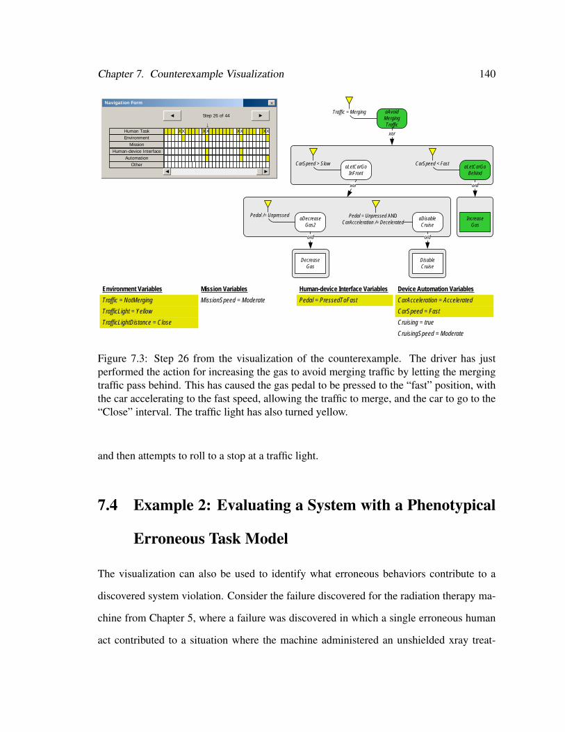
Chapter 7. Counterexample Visualization 140
aAvoidMergingTraffic
Traffic = Merging
xor
aLetCarGoInFront
CarSpeed > Slow
xor
aDecreaseGas2
Pedal /= Unpressed
ord
DecreaseGas
aDisableCruise
Pedal = Unpressed ANDCarAcceleration /= Decelerated
ord
DisableCruise
aLetCarGoBehind
CarSpeed < Fast
ord
IncreaseGas
Environment Variables
Traffic = NotMerging
TrafficLight = Yellow
TrafficLightDistance = Close
Mission Variables
MissionSpeed = Moderate
Human-device Interface Variables
Pedal = PressedToFast
Device Automation Variables
CarAcceleration = Accelerated
CarSpeed = Fast
Cruising = true
CruisingSpeed = Moderate
Step 26 of 44
↓
◄
Navigation Form
►
×
Human TaskEnvironment
MissionHuman-device Interface
Automation
X X X X XX XX
►◄
Other
Figure 7.3: Step 26 from the visualization of the counterexample. The driver has justperformed the action for increasing the gas to avoid merging traffic by letting the mergingtraffic pass behind. This has caused the gas pedal to be pressed to the “fast” position, withthe car accelerating to the fast speed, allowing the traffic to merge, and the car to go to the“Close” interval. The traffic light has also turned yellow.
and then attempts to roll to a stop at a traffic light.
7.4 Example 2: Evaluating a System with a Phenotypical
Erroneous Task Model
The visualization can also be used to identify what erroneous behaviors contribute to a
discovered system violation. Consider the failure discovered for the radiation therapy ma-
chine from Chapter 5, where a failure was discovered in which a single erroneous human
act contributed to a situation where the machine administered an unshielded xray treat-
Chapter 7. Counterexample Visualization 141
ment, a dangerous operating condition. We can use the visualization of a counterexample
illustrating this this failure sequence and use it to identify the erroneous behavior that con-
tributed to this problem.
The navigation form for the visualization of this counterexample shows us that a change
has occurred in the “Other” designation of variables at Step 5. Since the only variable in
the other designation is the erroneous behavior counter (ECount) we know that an erro-
neous behavior occurs beginning at this step. Examining this step (Figure 7.4) reveals that
the practitioner has just started performing the activity for performing an erroneous com-
mission (aPressECommission). We can then examine the two following steps (Step 7 is
shown in Figure 7.5) to see that the practitioner completes this activity by pressing the ‘X’
button which puts the interface into the state for displaying xray data, sets the beam to the
xray power level, and moves the spreader in place.
7.5 Example 3: Evaluating a System with a Knowledge-
based Erroneous Task Model
We can also use the counterexample visualizer to identify strategic knowledge-based erro-
neous behaviors that contribute a discovered system problems. For example, in the PCA
pump application (Chapter 6) a situation was discovered where a misapplication of strate-
gic knowledge resulted in a practitioner incorrectly programming the pump. The examina-
tion of the visualization of the counterexample illustrating this shows that a change in the
“Other” designation (the erroneous behavior counter KCount) occurs at step 32. An exam-
ination of this step (Figure 7.6) shows that the activity for changing the displayed value of
the delay between dosages (aChangeDelayValue) has erroneously transitioned from Exe-
cuting to Done without current displayed value (CurrentValue) matching the prescription
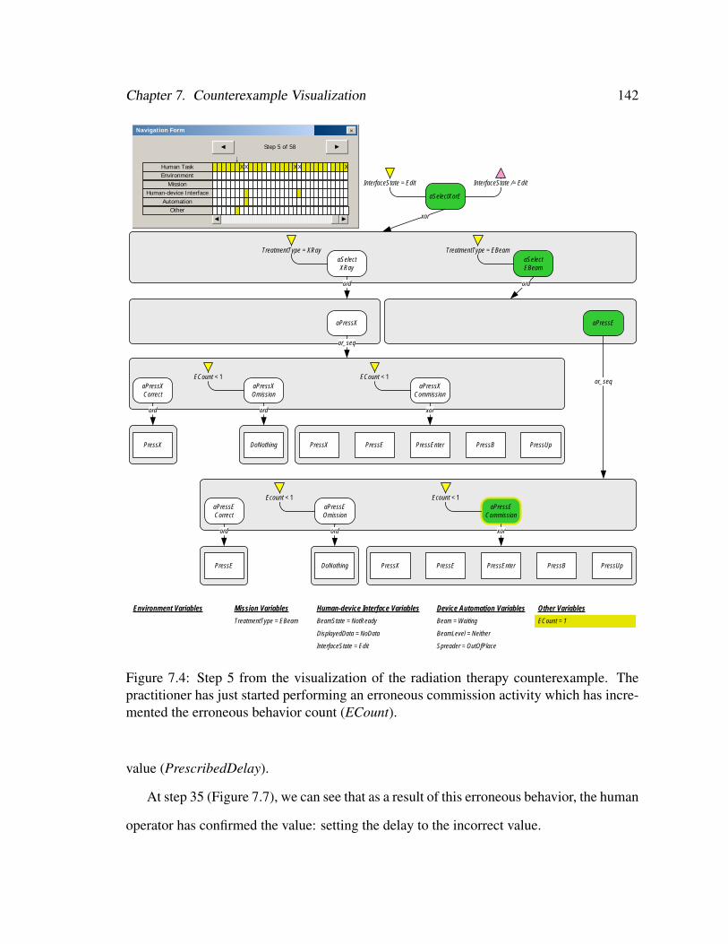
Chapter 7. Counterexample Visualization 142
aSelectXorE
InterfaceState = Edit InterfaceState /= Edit
xor
aSelectXRay
TreatmentType = XRay
ord
aPressX
or_seq
aPressXCorrect
ord
PressX
aPressXOmission
ECount < 1
ord
DoNothing
aPressXCommission
ECount < 1
xor
PressX PressE PressEnter PressB PressUp
aSelectEBeam
TreatmentType = EBeam
ord
aPressE
or_seq
aPressECorrect
ord
PressE
aPressEOmission
Ecount < 1
ord
DoNothing
aPressECommission
Ecount < 1
xor
PressX PressE PressEnter PressB PressUp
Environment Variables Mission Variables
TreatmentType = EBeam
Human-device Interface Variables
BeamState = NotReady
DisplayedData = NoData
InterfaceState = Edit
Device Automation Variables
Beam = Waiting
BeamLevel = Neither
Spreader = OutOfPlace
Other Variables
ECount = 1
Step 5 of 58
↓
◄
Navigation Form
►
×
Human TaskEnvironment
MissionHuman-device Interface
Automation
X X X X X
►◄
Other
Figure 7.4: Step 5 from the visualization of the radiation therapy counterexample. Thepractitioner has just started performing an erroneous commission activity which has incre-mented the erroneous behavior count (ECount).
value (PrescribedDelay).
At step 35 (Figure 7.7), we can see that as a result of this erroneous behavior, the human
operator has confirmed the value: setting the delay to the incorrect value.
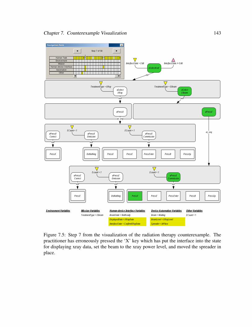
Chapter 7. Counterexample Visualization 143
aSelectXorE
InterfaceState = Edit InterfaceState /= Edit
xor
aSelectXRay
TreatmentType = XRay
ord
aPressX
or_seq
aPressXCorrect
ord
PressX
aPressXOmission
ECount < 1
ord
DoNothing
aPressXCommission
ECount < 1
xor
PressX PressE PressEnter PressB PressUp
aSelectEBeam
TreatmentType = EBeam
ord
aPressE
or_seq
aPressECorrect
ord
PressE
aPressEOmission
Ecount < 1
ord
DoNothing
aPressECommission
Ecount < 1
xor
PressX PressE PressEnter PressB PressUp
Environment Variables Mission Variables
TreatmentType = EBeam
Human-device Interface Variables
BeamState = NotReady
DisplayedData = XRayData
InterfaceState = ConfirmXRayData
Device Automation Variables
Beam = Waiting
BeamLevel = XRayLevel
Spreader = InPlace
Other Variables
ECount = 1
Step 7 of 58
↓
◄
Navigation Form
►
×
Human TaskEnvironment
MissionHuman-device Interface
Automation
X X X X X
►◄
Other
Figure 7.5: Step 7 from the visualization of the radiation therapy counterexample. Thepractitioner has erroneously pressed the ‘X’ key which has put the interface into the statefor displaying xray data, set the beam to the xray power level, and moved the spreader inplace.
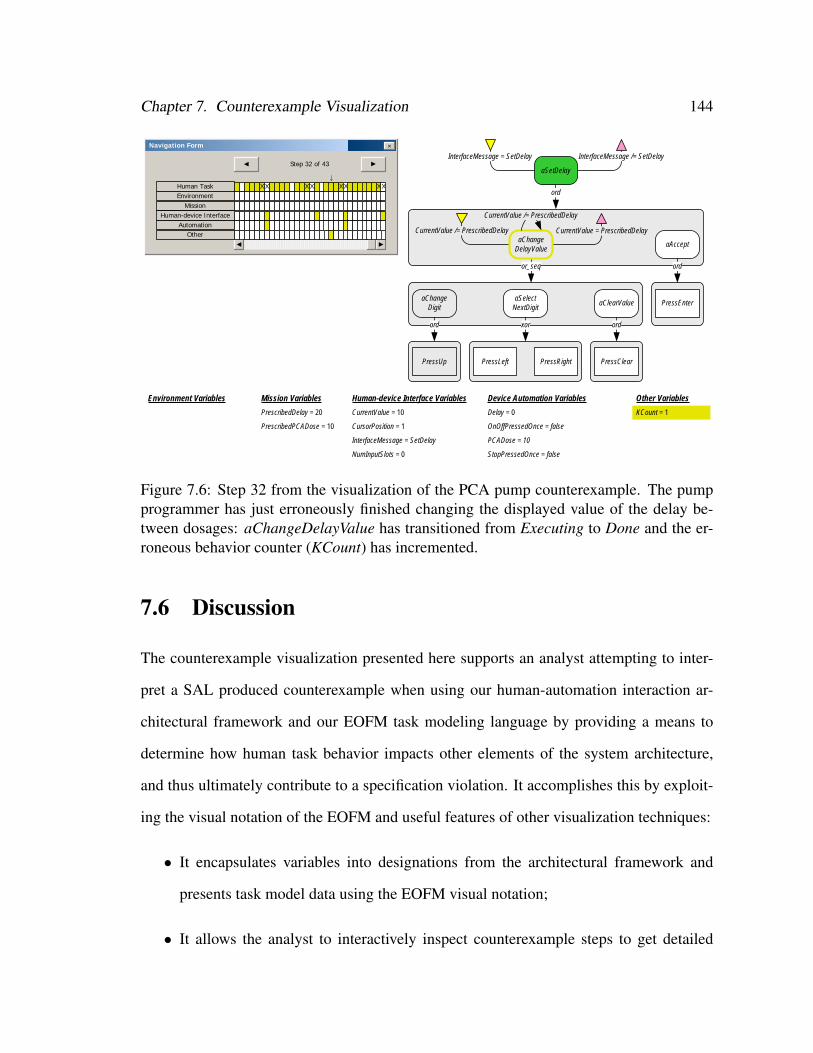
Chapter 7. Counterexample Visualization 144
CurrentValue /= PrescribedDelay
aSetDelay
InterfaceMessage = SetDelay InterfaceMessage /= SetDelay
ord
CurrentValue = PrescribedDelay
or_seq
aChangeDigit
ord
PressUp
aSelectNextDigit
xor
PressLeft PressRight
aClearValue
ord
PressClear
aAccept
ord
PressEnter
Environment Variables Mission Variables
PrescribedDelay = 20
PrescribedPCADose = 10
Human-device Interface Variables
CurrentValue = 10
CursorPosition = 1
InterfaceMessage = SetDelay
NumInputSlots = 0
Device Automation Variables
Delay = 0
OnOffPressedOnce = false
PCADose = 10
StopPressedOnce = false
Other Variables
KCount = 1
Step 32 of 43
↓
◄
Navigation Form
►
×
Human TaskEnvironment
MissionHuman-device Interface
Automation
X X X X XX XX
►◄
OtheraChange
DelayValue
CurrentValue /= PrescribedDelay
Figure 7.6: Step 32 from the visualization of the PCA pump counterexample. The pumpprogrammer has just erroneously finished changing the displayed value of the delay be-tween dosages: aChangeDelayValue has transitioned from Executing to Done and the er-roneous behavior counter (KCount) has incremented.
7.6 Discussion
The counterexample visualization presented here supports an analyst attempting to inter-
pret a SAL produced counterexample when using our human-automation interaction ar-
chitectural framework and our EOFM task modeling language by providing a means to
determine how human task behavior impacts other elements of the system architecture,
and thus ultimately contribute to a specification violation. It accomplishes this by exploit-
ing the visual notation of the EOFM and useful features of other visualization techniques:
• It encapsulates variables into designations from the architectural framework and
presents task model data using the EOFM visual notation;
• It allows the analyst to interactively inspect counterexample steps to get detailed
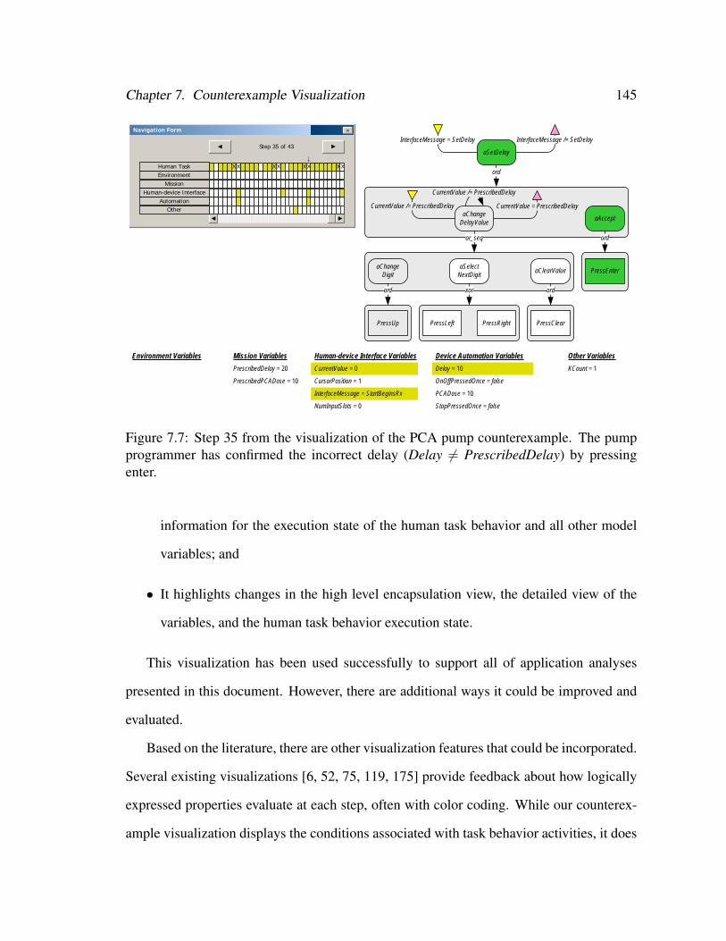
Chapter 7. Counterexample Visualization 145
CurrentValue /= PrescribedDelay
aSetDelay
InterfaceMessage = SetDelay InterfaceMessage /= SetDelay
ord
aChangeDelayValue
CurrentValue = PrescribedDelay
or_seq
aChangeDigit
ord
PressUp
aSelectNextDigit
xor
PressLeft PressRight
aClearValue
ord
PressClear
aAccept
ord
PressEnter
Environment Variables Mission Variables
PrescribedDelay = 20
PrescribedPCADose = 10
Human-device Interface Variables
CurrentValue = 0
CursorPosition = 1
InterfaceMessage = StartBeginsRx
NumInputSlots = 0
Device Automation Variables
Delay = 10
OnOffPressedOnce = false
PCADose = 10
StopPressedOnce = false
Other Variables
KCount = 1
Step 35 of 43
↓
◄
Navigation Form
►
×
Human TaskEnvironment
MissionHuman-device Interface
Automation
X X X X XX XX
►◄
Other
CurrentValue /= PrescribedDelay
Figure 7.7: Step 35 from the visualization of the PCA pump counterexample. The pumpprogrammer has confirmed the incorrect delay (Delay 6= PrescribedDelay) by pressingenter.
information for the execution state of the human task behavior and all other model
variables; and
• It highlights changes in the high level encapsulation view, the detailed view of the
variables, and the human task behavior execution state.
This visualization has been used successfully to support all of application analyses
presented in this document. However, there are additional ways it could be improved and
evaluated.
Based on the literature, there are other visualization features that could be incorporated.
Several existing visualizations [6, 52, 75, 119, 175] provide feedback about how logically
expressed properties evaluate at each step, often with color coding. While our counterex-
ample visualization displays the conditions associated with task behavior activities, it does
Chapter 7. Counterexample Visualization 146
not provide any visual indication of how they evaluate (true or false). Additionally, our
visualization provides no feedback about the evaluation of temporal logic properties (like
that used to produce the counterexample). Future work should investigate how to incorpo-
rate visual feedback about property evaluations into our visualization.
Several of the tools we discussed [6, 52, 75] allow analysts to interactively explore the
state space of a model. The counterexamples produced by SAL-SMC represent a single
execution path through the model, and thus do not support additional model exploration.
However, SAL does have a simulator that supports exploration. Future work should inves-
tigate how our visualization could be made to work with SAL’s simulator.
Our visualization was explicitly designed to help analysts interpret counterexamples.
However, such a visualization may be useful for debugging models during development.
Future work should determine what the requirements are for debugging and related visual-
ization tools.
Our visualization has only been used to examine single counterexamples in isolation.
However, it is conceivable that analysts may wish to compare different counterexamples
in order to diagnose potentially related specification violations. Future work should inves-
tigate what the requirements are for such a feature and possibly adapt the visualization to
support it.
Finally, future work should evaluate our visualization with a human subject experiment;
where we would evaluate whether analysts could identify executing human task behavior
and its impact on other system variables more efficiently with our visualization than with
a typical SAL counterexample. Future work should also investigate how our visualization
compares to other visualization techniques such as variable tables and sequence diagrams.
This is discussed in greater depth in Chapter 9.
Chapter 8
Design Exploration
All of the examples up to this point have illustrated a particular feature of our method. In
this chapter, we show how our method can be used to evaluate the design of a human-
automation interactive system in a number of different ways. We describe a human-
automation interaction issue associated the deployment of spoilers with an aircraft on
approach in which the pilot is performing the before landing checklist (a Douglas DC-8
application inspired by [67]). In these analyses we use a formal system model contain-
ing all elements of the human-automation interaction architectural framework. Across the
analyses we show how our method can be used to explore the impact of different norma-
tive task behaviors, erroneous human behavior generated using the methods discussed in
Chapter 5 and Chapter 6, and degraded performance of the device automation. Potential
interventions to discovered problems are explored.
8.1 Application: Aircraft on Approach
In most instrument landing systems, an aircraft pilot must position the aircraft so that it
will align with the runways glideslope: a diagonal path (3◦ from horizontal) to help pilots
147
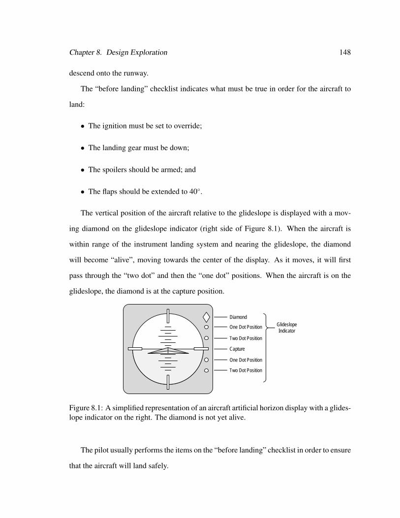
Chapter 8. Design Exploration 148
descend onto the runway.
The “before landing” checklist indicates what must be true in order for the aircraft to
land:
• The ignition must be set to override;
• The landing gear must be down;
• The spoilers should be armed; and
• The flaps should be extended to 40◦.
The vertical position of the aircraft relative to the glideslope is displayed with a mov-
ing diamond on the glideslope indicator (right side of Figure 8.1). When the aircraft is
within range of the instrument landing system and nearing the glideslope, the diamond
will become “alive”, moving towards the center of the display. As it moves, it will first
pass through the “two dot” and then the “one dot” positions. When the aircraft is on the
glideslope, the diamond is at the capture position.
Glideslope Indicator
One Dot Position
Two Dot Position
Diamond
Capture
One Dot Position
Two Dot Position
Figure 8.1: A simplified representation of an aircraft artificial horizon display with a glides-lope indicator on the right. The diamond is not yet alive.
The pilot usually performs the items on the “before landing” checklist in order to ensure
that the aircraft will land safely.
Chapter 8. Design Exploration 149
The ignition should be set to override in order to ensure that, should the engine quite,
there will be enough ignition power to restart it. The ignition is controlled by a switch, and
a light illuminates when the switch is set to override.
Once the glideslope indicator diamond is alive, the pilot can deploy the landing gear.
Pulling the landing gear lever opens the landing gear doors and deploys the gear. In a well
functioning aircraft the doors can take approximately 10 seconds to completely open. As
such, the landing gear will fully deploy before the landing gear doors are completely open.
Three lights in the cockpit (one for each of the landing gear) illuminate when the landing
gear is fully deployed. Another light illuminates when the landing gear doors begin to
open, and remains on until they are completely open.
The pilot progressively extends the flaps in order to reduce the aircraft’s stalling speed,
thereby allowing the aircraft to fly safely at slower speeds. Extending flaps also increases
drag which helps to slow the aircraft. In general, when the aircraft is between the one dot
and capture positions, the pilot has slowed to a speed where the flaps should be set to 25◦.
When the aircraft has reached the capture position he should set the flaps to 40◦. Pilots
may also set the flaps to progressive intermediate degrees before and/or in between these
two settings. The position of the flaps is indicated by a gauge in the cockpit.
Spoilers are retractable plates on the wings of the aircraft which, when deployed, de-
crease the lift of the aircraft. They are deployed during landing to prevent the aircraft from
lifting off of the runway. Spoilers can be deployed manually or automatically. The pilot
can arm the spoilers for automatic deployment by pulling a lever. A light in the cockpit in-
dicates when the spoiler are armed. Alternatively, a pilot can manually deploy the spoilers
when the aircraft touches the runway.
Chapter 8. Design Exploration 150
8.1.1 Problems with Spoilers
Two potential problems have been identified relating to the deployment of spoilers. Firstly,
if the spoilers are never deployed (either via automatic or manual deployment) this can
result in the aircraft overrunning the runway as occurred with American Airlines Flight
1420 [145]. Secondly, having the spoilers deploy in flight will result in the aircraft losing
lift possibly resulting in a hard landing or a crash. This was the case with Air Canada flight
621 [83] and Loftleidir Flight 509 [84], both Douglas DC-8s.
The first condition can occur if the pilot forgets to arm the spoilers (as happened with
American Airlines Flight 1420 [145]). The second problem can also result from this,
where the pilot attempts to correct the problem but, because he is unfamiliar with man-
ual spoiler deployment, he prematurely deploys the spoilers manually (this was the case
for Air Canada flight 621 [83]). However, the second problem can also occur due to the
mechanism that automatically deploys the spoilers. If spoilers are armed before the land-
ing gear has deployed or the landing gear doors have fully opened, the armed spoilers may
automatically deploy [67].
8.1.2 Objectives
We evaluate issues related to spoiler arming for this application using our method. We
exploit the modular nature of our architecture to run a series of verifications to explore
the behavior of the system and potential solutions to discovered problems. This analysis
occurs across the following phases:
1. We explore different representations of normative human behavior;
2. We explore different representations of erroneous human behavior; and
3. We explore variations in the behavior of the automation.
Chapter 8. Design Exploration 151
However, first we discuss the EOFM and formal system models on which these analy-
ses were performed.
8.2 Formal System Model
The formal system model was constructed around our architecture [27, 31] with models
of the operational environment, device automation, human-device interface, human (pilot)
mission, and human task behavior.
8.2.1 Operational Environment
The operational environment of an actual aircraft includes the weather, air traffic, air traffic
control, and the state of the runways (among other things). For our purposes, the environ-
ment is modeled as the relative distance of the aircraft from the capture position on the
glideslope. It is assumed that the aircraft starts at a position in which the glideslope dia-
mond is not alive, and that the aircraft proceeds up to the capture positions and begins to
descend on the glideslope, a process that will take 18 seconds. Thus, the relative position
of the aircraft from its modeled initial position is discretized into intervals from 0 to 18
such that the aircraft passes from one interval to the next in one second (Figure 8.2). This
means the aircraft speed and altitude are abstracted into the position.
In our model, the glideslope indicator diamond’s behavior is directly associated with
the aircraft’s position. The aircraft starts at position 0 where the glideslope diamond is not
alive. At position 1, the glideslope diamond becomes alive. At position 6 the aircraft is
“two dots” below the glideslope. It is “one dot” below at position 11. Capture occurs at
position 17. At position 18, the aircraft is in the process of landing.
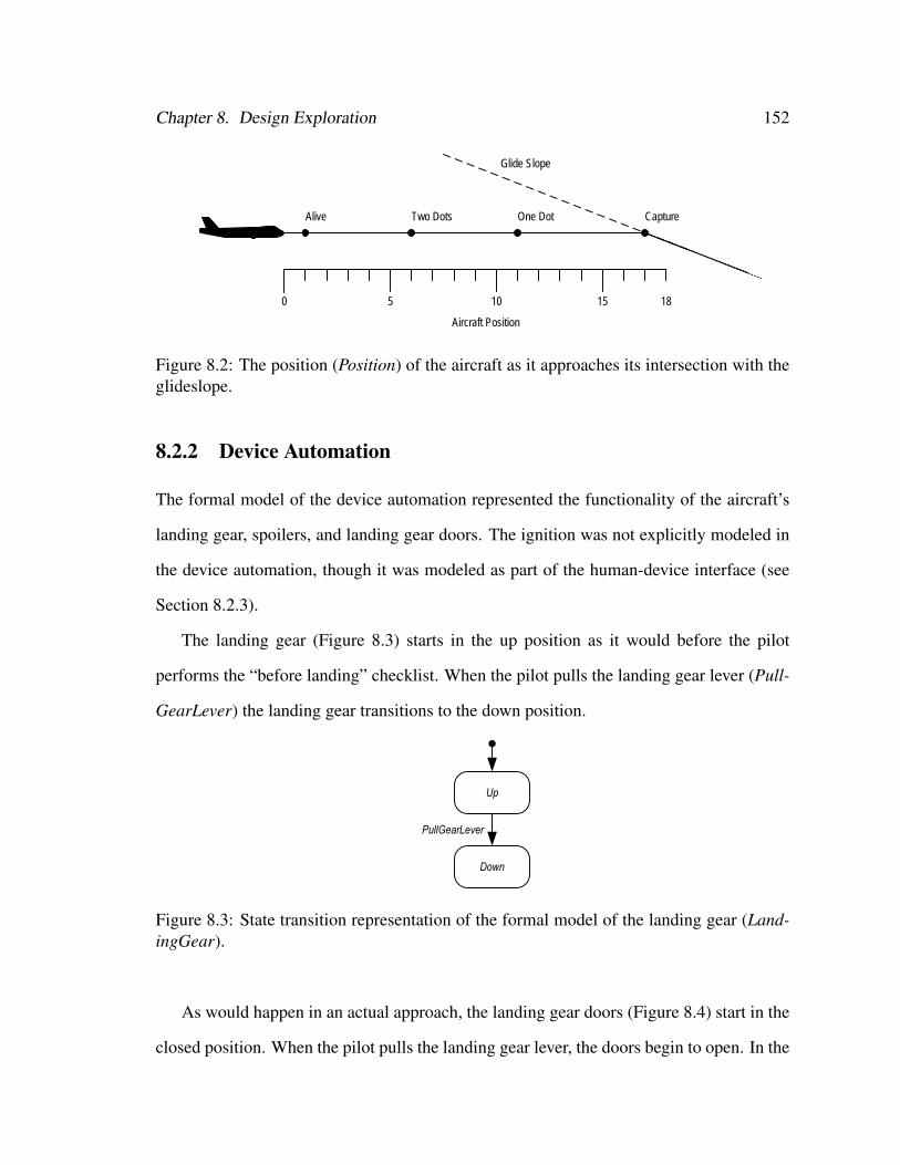
Chapter 8. Design Exploration 152
0 5 10 15 18
Glide Slope
Alive Two Dots One Dot Capture
Aircraft Position
Figure 8.2: The position (Position) of the aircraft as it approaches its intersection with theglideslope.
8.2.2 Device Automation
The formal model of the device automation represented the functionality of the aircraft’s
landing gear, spoilers, and landing gear doors. The ignition was not explicitly modeled in
the device automation, though it was modeled as part of the human-device interface (see
Section 8.2.3).
The landing gear (Figure 8.3) starts in the up position as it would before the pilot
performs the “before landing” checklist. When the pilot pulls the landing gear lever (Pull-
GearLever) the landing gear transitions to the down position.
Figure 8.3: State transition representation of the formal model of the landing gear (Land-ingGear).
As would happen in an actual approach, the landing gear doors (Figure 8.4) start in the
closed position. When the pilot pulls the landing gear lever, the doors begin to open. In the
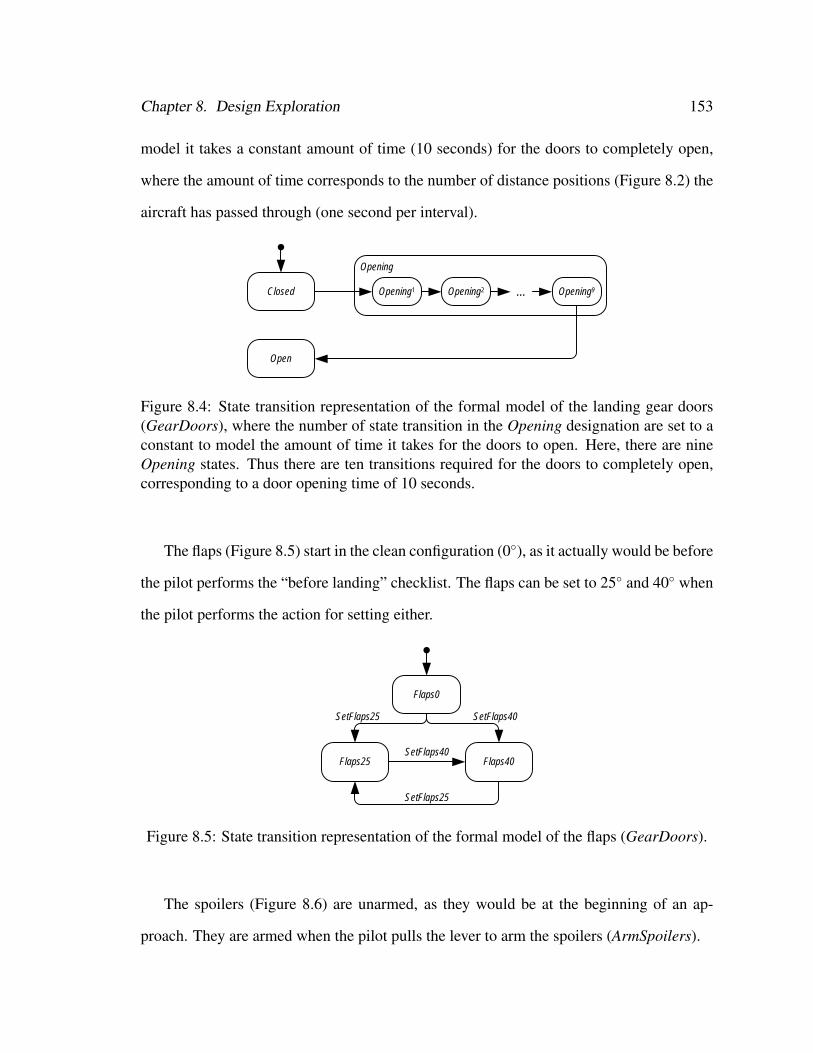
Chapter 8. Design Exploration 153
model it takes a constant amount of time (10 seconds) for the doors to completely open,
where the amount of time corresponds to the number of distance positions (Figure 8.2) the
aircraft has passed through (one second per interval).
Opening
Closed
Open
Opening1 Opening9Opening2 ...
Figure 8.4: State transition representation of the formal model of the landing gear doors(GearDoors), where the number of state transition in the Opening designation are set to aconstant to model the amount of time it takes for the doors to open. Here, there are nineOpening states. Thus there are ten transitions required for the doors to completely open,corresponding to a door opening time of 10 seconds.
The flaps (Figure 8.5) start in the clean configuration (0◦), as it actually would be before
the pilot performs the “before landing” checklist. The flaps can be set to 25◦ and 40◦ when
the pilot performs the action for setting either.
Flaps0
Flaps25
SetFlaps25
Flaps40
SetFlaps25 SetFlaps40
SetFlaps40
Figure 8.5: State transition representation of the formal model of the flaps (GearDoors).
The spoilers (Figure 8.6) are unarmed, as they would be at the beginning of an ap-
proach. They are armed when the pilot pulls the lever to arm the spoilers (ArmSpoilers).
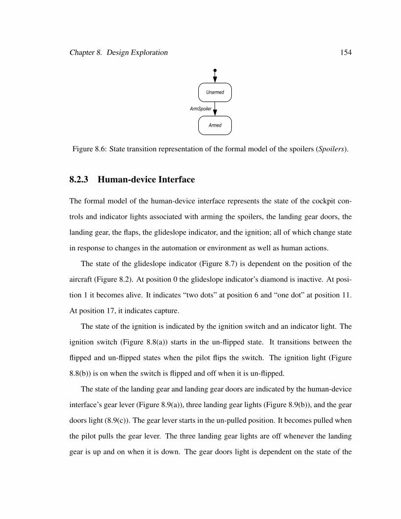
Chapter 8. Design Exploration 154
Figure 8.6: State transition representation of the formal model of the spoilers (Spoilers).
8.2.3 Human-device Interface
The formal model of the human-device interface represents the state of the cockpit con-
trols and indicator lights associated with arming the spoilers, the landing gear doors, the
landing gear, the flaps, the glideslope indicator, and the ignition; all of which change state
in response to changes in the automation or environment as well as human actions.
The state of the glideslope indicator (Figure 8.7) is dependent on the position of the
aircraft (Figure 8.2). At position 0 the glideslope indicator’s diamond is inactive. At posi-
tion 1 it becomes alive. It indicates “two dots” at position 6 and “one dot” at position 11.
At position 17, it indicates capture.
The state of the ignition is indicated by the ignition switch and an indicator light. The
ignition switch (Figure 8.8(a)) starts in the un-flipped state. It transitions between the
flipped and un-flipped states when the pilot flips the switch. The ignition light (Figure
8.8(b)) is on when the switch is flipped and off when it is un-flipped.
The state of the landing gear and landing gear doors are indicated by the human-device
interface’s gear lever (Figure 8.9(a)), three landing gear lights (Figure 8.9(b)), and the gear
doors light (8.9(c)). The gear lever starts in the un-pulled position. It becomes pulled when
the pilot pulls the gear lever. The three landing gear lights are off whenever the landing
gear is up and on when it is down. The gear doors light is dependent on the state of the
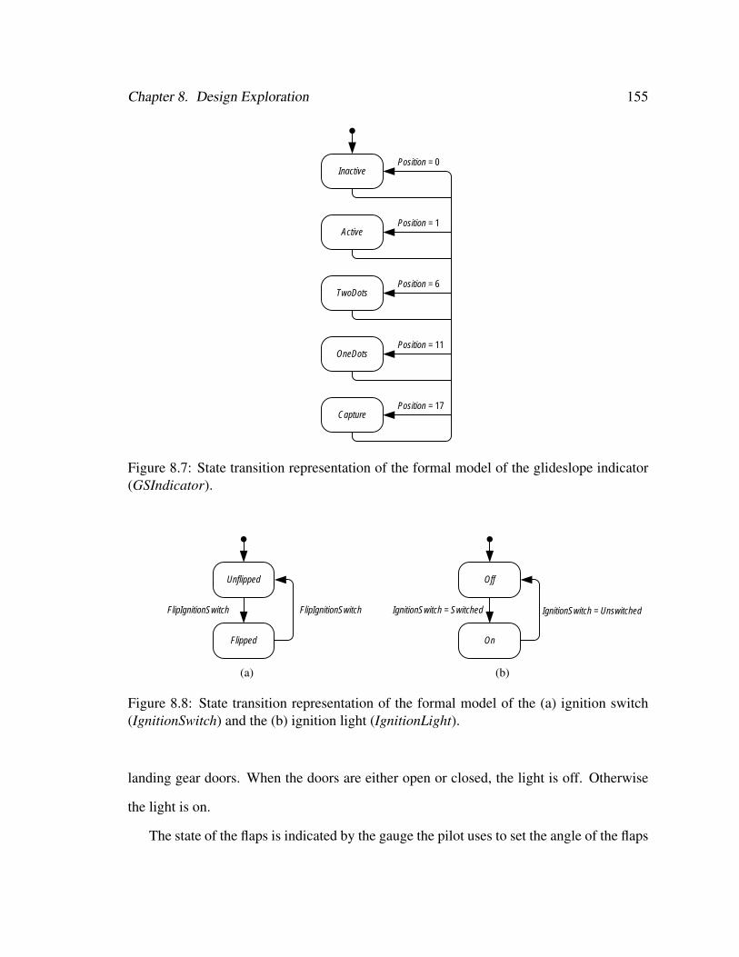
Chapter 8. Design Exploration 155
Inactive
Active
TwoDots
OneDots
Capture
Position = 1
Position = 0
Position = 6
Position = 11
Position = 17
Figure 8.7: State transition representation of the formal model of the glideslope indicator(GSIndicator).
Unflipped
Flipped
FlipIgnitionSwitch FlipIgnitionSwitch
(a)
Off
On
IgnitionSwitch = Switched IgnitionSwitch = Unswitched
(b)
Figure 8.8: State transition representation of the formal model of the (a) ignition switch(IgnitionSwitch) and the (b) ignition light (IgnitionLight).
landing gear doors. When the doors are either open or closed, the light is off. Otherwise
the light is on.
The state of the flaps is indicated by the gauge the pilot uses to set the angle of the flaps
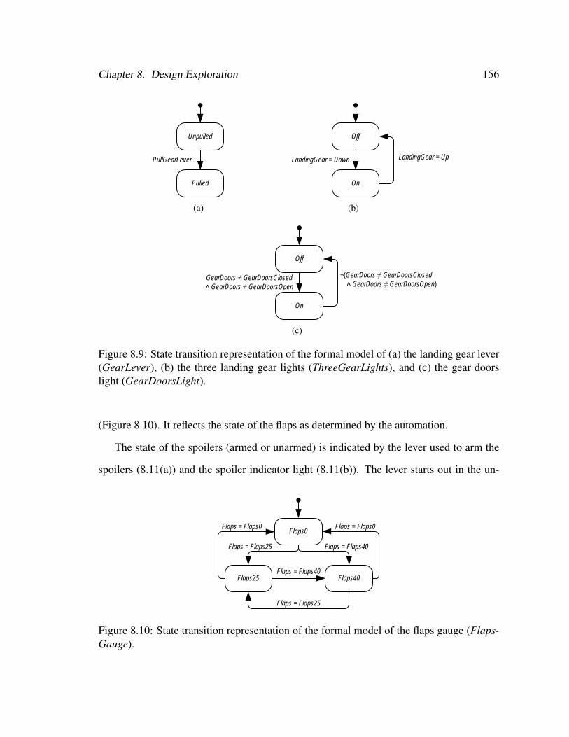
Chapter 8. Design Exploration 156
Unpulled
Pulled
PullGearLever
(a)
Off
On
LandingGear = Down LandingGear = Up
(b)
Off
On
GearDoors ≠ GearDoorsClosed ˄ GearDoors ≠ GearDoorsOpen
¬(GearDoors ≠ GearDoorsClosed ˄ GearDoors ≠ GearDoorsOpen)
(c)
Figure 8.9: State transition representation of the formal model of (a) the landing gear lever(GearLever), (b) the three landing gear lights (ThreeGearLights), and (c) the gear doorslight (GearDoorsLight).
(Figure 8.10). It reflects the state of the flaps as determined by the automation.
The state of the spoilers (armed or unarmed) is indicated by the lever used to arm the
spoilers (8.11(a)) and the spoiler indicator light (8.11(b)). The lever starts out in the un-
Flaps0
Flaps25
Flaps = Flaps25
Flaps = Flaps0
Flaps40
Flaps = Flaps0
Flaps = Flaps25 Flaps = Flaps40
Flaps = Flaps40
Figure 8.10: State transition representation of the formal model of the flaps gauge (Flaps-Gauge).
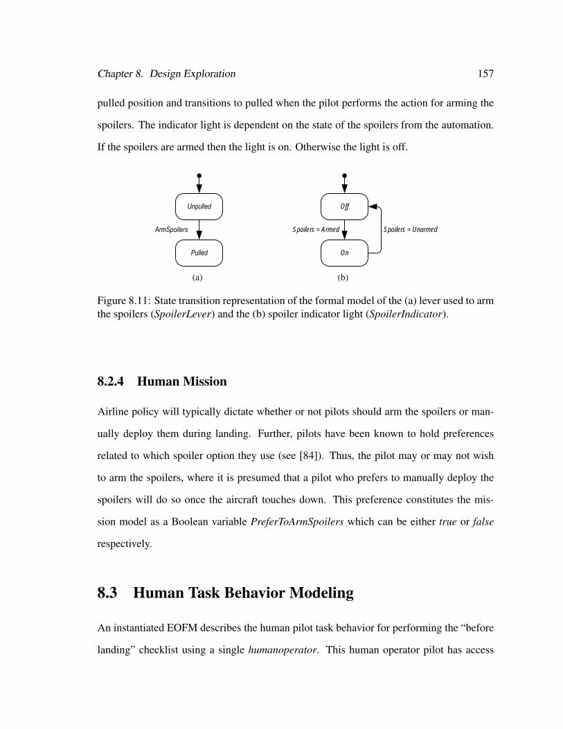
Chapter 8. Design Exploration 157
pulled position and transitions to pulled when the pilot performs the action for arming the
spoilers. The indicator light is dependent on the state of the spoilers from the automation.
If the spoilers are armed then the light is on. Otherwise the light is off.
(a)
Off
On
Spoilers = UnarmedSpoilers = Armed
(b)
Figure 8.11: State transition representation of the formal model of the (a) lever used to armthe spoilers (SpoilerLever) and the (b) spoiler indicator light (SpoilerIndicator).
8.2.4 Human Mission
Airline policy will typically dictate whether or not pilots should arm the spoilers or man-
ually deploy them during landing. Further, pilots have been known to hold preferences
related to which spoiler option they use (see [84]). Thus, the pilot may or may not wish
to arm the spoilers, where it is presumed that a pilot who prefers to manually deploy the
spoilers will do so once the aircraft touches down. This preference constitutes the mis-
sion model as a Boolean variable PreferToArmSpoilers which can be either true or false
respectively.
8.3 Human Task Behavior Modeling
An instantiated EOFM describes the human pilot task behavior for performing the “before
landing” checklist using a single humanoperator. This human operator pilot has access
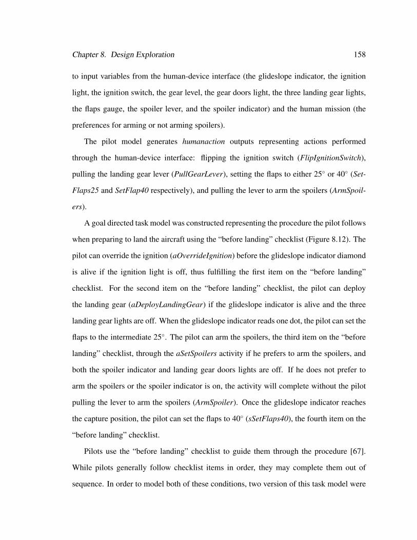
Chapter 8. Design Exploration 158
to input variables from the human-device interface (the glideslope indicator, the ignition
light, the ignition switch, the gear level, the gear doors light, the three landing gear lights,
the flaps gauge, the spoiler lever, and the spoiler indicator) and the human mission (the
preferences for arming or not arming spoilers).
The pilot model generates humanaction outputs representing actions performed
through the human-device interface: flipping the ignition switch (FlipIgnitionSwitch),
pulling the landing gear lever (PullGearLever), setting the flaps to either 25◦ or 40◦ (Set-
Flaps25 and SetFlap40 respectively), and pulling the lever to arm the spoilers (ArmSpoil-
ers).
A goal directed task model was constructed representing the procedure the pilot follows
when preparing to land the aircraft using the “before landing” checklist (Figure 8.12). The
pilot can override the ignition (aOverrideIgnition) before the glideslope indicator diamond
is alive if the ignition light is off, thus fulfilling the first item on the “before landing”
checklist. For the second item on the “before landing” checklist, the pilot can deploy
the landing gear (aDeployLandingGear) if the glideslope indicator is alive and the three
landing gear lights are off. When the glideslope indicator reads one dot, the pilot can set the
flaps to the intermediate 25◦. The pilot can arm the spoilers, the third item on the “before
landing” checklist, through the aSetSpoilers activity if he prefers to arm the spoilers, and
both the spoiler indicator and landing gear doors lights are off. If he does not prefer to
arm the spoilers or the spoiler indicator is on, the activity will complete without the pilot
pulling the lever to arm the spoilers (ArmSpoiler). Once the glideslope indicator reaches
the capture position, the pilot can set the flaps to 40◦ (sSetFlaps40), the fourth item on the
“before landing” checklist.
Pilots use the “before landing” checklist to guide them through the procedure [67].
While pilots generally follow checklist items in order, they may complete them out of
sequence. In order to model both of these conditions, two version of this task model were
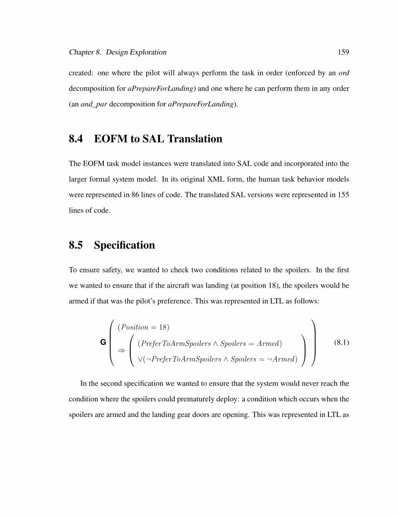
Chapter 8. Design Exploration 159
created: one where the pilot will always perform the task in order (enforced by an ord
decomposition for aPrepareForLanding) and one where he can perform them in any order
(an and_par decomposition for aPrepareForLanding).
8.4 EOFM to SAL Translation
The EOFM task model instances were translated into SAL code and incorporated into the
larger formal system model. In its original XML form, the human task behavior models
were represented in 86 lines of code. The translated SAL versions were represented in 155
lines of code.
8.5 Specification
To ensure safety, we wanted to check two conditions related to the spoilers. In the first
we wanted to ensure that if the aircraft was landing (at position 18), the spoilers would be
armed if that was the pilot’s preference. This was represented in LTL as follows:
G
(Position = 18)
⇒
(PreferToArmSpoilers ∧ Spoilers = Armed)
∨(¬PreferToArmSpoilers ∧ Spoilers = ¬Armed)
(8.1)
In the second specification we wanted to ensure that the system would never reach the
condition where the spoilers could prematurely deploy: a condition which occurs when the
spoilers are armed and the landing gear doors are opening. This was represented in LTL as
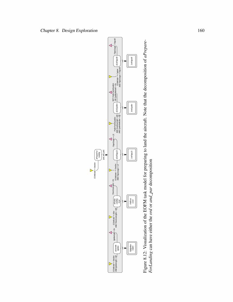
Chapter 8. Design Exploration 160
aPre
pare
For
Land
ing
GSI
ndic
ator
<=
Inac
tive
{ord
, and
_par
}
aOve
rride
Igni
tion
GSI
ndic
ator
<=
Inac
tive
AND
Igni
tionL
ight
= O
ffIg
nitio
nLig
ht =
On
ord
Flip
Igni
tion
Switc
h
aDep
loy
Land
ing
Gea
r
GSI
ndic
ator
<=
Aliv
eAN
D T
hree
Gea
rLig
hts
= O
ff
Thre
eGea
rLig
hts
= O
n
ord
PullG
ear
Leve
r
aSet
Flap
s25
GSI
ndic
ator
<=
One
Dot
AND
Fla
psG
auge
/= 2
5
ord
SetF
laps
25
aSet
Spoi
lers
Pref
erTo
Arm
Spoi
lers
AN
D G
earD
oorL
ight
= O
ff AN
D S
poile
rIndi
cato
r = O
ff
NO
T Pr
efer
ToAr
mSp
oile
rsO
R S
poile
rIndi
cato
r = O
n
ord
Arm
Spoi
ler
aSet
Flap
s40
GSI
ndic
ator
<=
Cap
ture
AND
Fla
psG
auge
/= F
laps
40
Flap
sGau
ge =
Fla
ps40
ord
SetF
laps
40
Flap
sGau
ge >
= 25
Figu
re8.
12:
Vis
ualiz
atio
nof
the
EO
FMta
skm
odel
forp
repa
ring
tola
ndth
eai
rcra
ft.N
ote
that
the
deco
mpo
sitio
nof
aPre
pare
-Fo
rLan
ding
can
have
eith
erth
eor
dor
and_
par
deco
mpo
sitio
n

Chapter 8. Design Exploration 161
follows:
G¬
Spoilers = Armed
∧GearDoors 6= Closed
∧GearDoors 6= Open
(8.2)
8.6 Apparatus
All verifications were completed using SAL-SMC 3.0, the SAL symbolic model checker.
Verifications were conducted on a 3.0 gigahertz dual-core Intel Xeon processor with 16
gigabytes of RAM running the Ubuntu 9.04 desktop.
8.7 Phase 1 Analyses: Exploring Different Representa-
tions of Normative Human Behavior
8.7.1 Modeling
In the first set of analyses, formal verifications were run for (8.1) and (8.2) on two versions
of the formal system model: one in which the human task behavior model used the ord
decomposition operator to ensure all activities are performed in order and one in which the
and_par decomposition operator is used to allow activities to be performed in any order.
8.7.2 Verification Results
For the model employing the human task behavior with the ord decomposition operator,
both (8.1) and (8.2) verified to true (239 visited states in 1.14 seconds and 239 visited states
in 1.12 seconds respectively).

Chapter 8. Design Exploration 162
For the system model using the human task behavior with the and_par decomposition
operator, (8.1) verified to true (725 visited states in 1.18 seconds). However, the verification
of (8.2) returned a counterexample after 0.58 seconds.
When this counterexample was examined using the visualizer, it revealed that the pilot’s
first action was to arm the spoilers (Figure 8.13). He followed this by deploying the aircraft
landing gear, an action that resulted in the landing gear doors opening (Figure 8.14). Thus
a violation of (8.2) occurred with the landing gear doors opening while the spoilers were
armed.
8.7.3 Discussion
There are a number of different ways in which this problem could be addressed. Resolution
could come through changes to the automation. For example, the spoiler system could be
redesigned so that the spoilers could be armed while the landing gear doors are opening
without risk of premature deployment. In such a situation it would be unnecessary to even
check (8.2). However, such a solution may require an expensive retrofit if the aircraft is
already in operation. Another possible solution would be to implement a forcing function
[142] to prevent the pilot from being able to arm the spoilers before the landing gear doors
are open. However, this solution would also have associated expense and could artificially
limit the procedures pilots could use to mitigate emergencies.
Another solution could change the pilot’s mission: where pilots are not allowed to have
a preference about arming spoilers and would only be allowed to deploy them manually.
This modification eliminates the violation without introducing a new one: (8.1) and (8.2)
verified to true in just over a second having visited 118 states for the ord model and in 204
states for the and_par model. However, this may also not be a desirable solution as it could
lead to an increase in pilots manually deploying spoilers prematurely, a problem that has
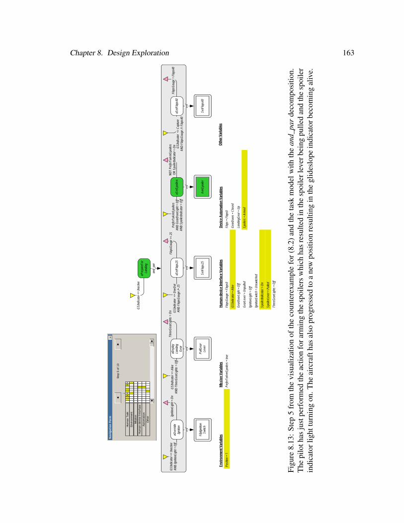
Chapter 8. Design Exploration 163
Oth
er V
aria
bles
aPre
pare
For
Land
ing
GSI
ndic
ator
<=
Inac
tive
and_
par
aOve
rride
Igni
tion
GSI
ndic
ator
<=
Inac
tive
AND
Igni
tionL
ight
= O
ffIg
nitio
nLig
ht =
On
ord
Flip
Igni
tion
Switc
h
aDep
loy
Land
ing
Gea
r
GSI
ndic
ator
<=
Aliv
eAN
D T
hree
Gea
rLig
hts
= O
ff
Thre
eGea
rLig
hts
= O
n
ord
PullG
ear
Leve
r
aSet
Flap
s25
GSI
ndic
ator
<=
One
Dot
AND
Fla
psG
auge
/= 2
5
ord
SetF
laps
25
aSet
Spoi
lers
Pref
erTo
Arm
Spoi
lers
AN
D G
earD
oorL
ight
= O
ff AN
D S
poile
rIndi
cato
r = O
ff
NO
T Pr
efer
ToAr
mSp
oile
rsO
R S
poile
rIndi
cato
r = O
n
ord
Arm
Spoi
ler
aSet
Flap
s40
GSI
ndic
ator
<=
Cap
ture
AND
Fla
psG
auge
/= F
laps
40
Flap
sGau
ge =
Fla
ps40
ord
SetF
laps
40
Flap
sGau
ge >
= 25
Envi
ronm
ent V
aria
bles
Posi
tion
= 1
Mis
sion
Var
iabl
es
Pref
erTo
Arm
Spoi
lers
= tr
ue
Hum
an-d
evic
e In
terf
ace
Varia
bles
Flap
sGau
ge =
Fla
ps0
GSI
ndic
ator
= A
live
Gea
rDoo
rLig
ht =
Off
Gea
rLev
er =
Unp
ulle
d
Igni
tionL
ight
= O
ff
Igni
tionS
witc
h =
Uns
witc
hed
Spoi
lerIn
dica
tor =
On
Spoi
lerL
ever
= P
ulle
d
Thre
eGea
rLig
hts
= O
ff
Dev
ice
Aut
omat
ion
Varia
bles
Flap
s =
Flap
s0
Gea
rDoo
rs =
Clo
sed
Land
ingG
ear =
Up
Spoi
lers
= A
rmed
Step
5 o
f 10
↓
◄
Nav
igat
ion
Form
►
×
Hum
an T
ask
Envi
ronm
ent
Mis
sion
Hum
an-d
evic
e In
terf
ace
Auto
mat
ion
XX
XX
►◄
Oth
er
Figu
re8.
13:
Step
5fr
omth
evi
sual
izat
ion
ofth
eco
unte
rexa
mpl
efo
r(8.
2)an
dth
eta
skm
odel
with
the
and_
par
deco
mpo
sitio
n.T
hepi
loth
asju
stpe
rfor
med
the
actio
nfo
rarm
ing
the
spoi
lers
whi
chha
sre
sulte
din
the
spoi
lerl
ever
bein
gpu
lled
and
the
spoi
ler
indi
cato
rlig
httu
rnin
gon
.The
airc
raft
has
also
prog
ress
edto
ane
wpo
sitio
nre
sulti
ngin
the
glid
eslo
pein
dica
torb
ecom
ing
aliv
e.
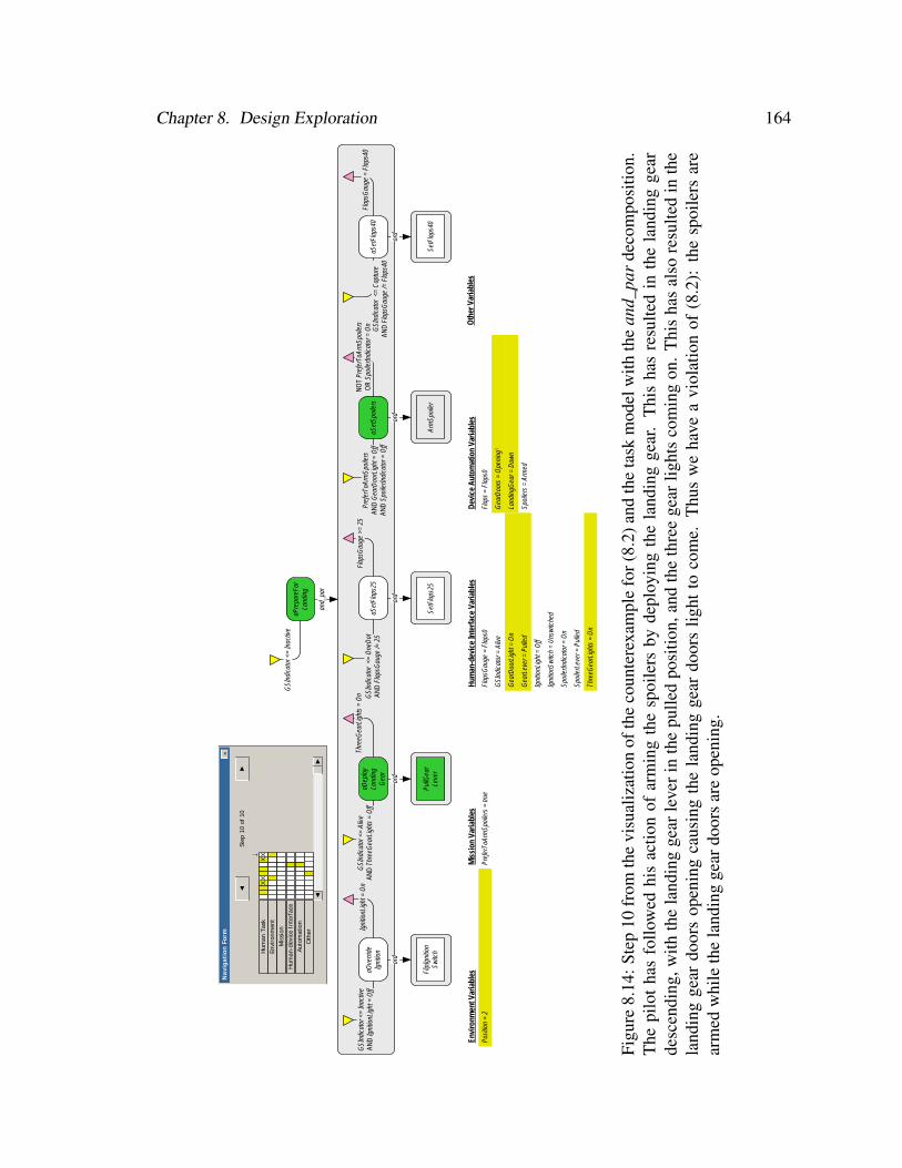
Chapter 8. Design Exploration 164
Oth
er V
aria
bles
aPre
pare
For
Land
ing
GSI
ndic
ator
<=
Inac
tive
and_
par
aOve
rride
Igni
tion
GSI
ndic
ator
<=
Inac
tive
AND
Igni
tionL
ight
= O
ffIg
nitio
nLig
ht =
On
ord
Flip
Igni
tion
Switc
h
aDep
loy
Land
ing
Gea
r
GSI
ndic
ator
<=
Aliv
eAN
D T
hree
Gea
rLig
hts
= O
ff
Thre
eGea
rLig
hts
= O
n
ord
PullG
ear
Leve
r
aSet
Flap
s25
GSI
ndic
ator
<=
One
Dot
AND
Fla
psG
auge
/= 2
5
ord
SetF
laps
25
aSet
Spoi
lers
Pref
erTo
Arm
Spoi
lers
AN
D G
earD
oorL
ight
= O
ff AN
D S
poile
rIndi
cato
r = O
ff
NO
T Pr
efer
ToAr
mSp
oile
rsO
R S
poile
rIndi
cato
r = O
n
ord
Arm
Spoi
ler
aSet
Flap
s40
GSI
ndic
ator
<=
Cap
ture
AND
Fla
psG
auge
/= F
laps
40
Flap
sGau
ge =
Fla
ps40
ord
SetF
laps
40
Flap
sGau
ge >
= 25
Envi
ronm
ent V
aria
bles
Posi
tion
= 2
Mis
sion
Var
iabl
es
Pref
erTo
Arm
Spoi
lers
= tr
ue
Hum
an-d
evic
e In
terf
ace
Varia
bles
Flap
sGau
ge =
Fla
ps0
GSI
ndic
ator
= A
live
Gea
rDoo
rLig
ht =
On
Gea
rLev
er =
Pul
led
Igni
tionL
ight
= O
ff
Igni
tionS
witc
h =
Uns
witc
hed
Spoi
lerIn
dica
tor =
On
Spoi
lerL
ever
= P
ulle
d
Thre
eGea
rLig
hts
= O
n
Dev
ice
Aut
omat
ion
Varia
bles
Flap
s =
Flap
s0
Gea
rDoo
rs =
Ope
ning
1
Land
ingG
ear =
Dow
n
Spoi
lers
= A
rmed
Step
10
of 1
0
↓
◄
Nav
igat
ion
Form
►
×
Hum
an T
ask
Envi
ronm
ent
Mis
sion
Hum
an-d
evic
e In
terf
ace
Auto
mat
ion
XX
XX
►◄
Oth
er
Figu
re8.
14:S
tep
10fr
omth
evi
sual
izat
ion
ofth
eco
unte
rexa
mpl
efo
r(8.
2)an
dth
eta
skm
odel
with
the
and_
par
deco
mpo
sitio
n.T
hepi
lot
has
follo
wed
his
actio
nof
arm
ing
the
spoi
lers
byde
ploy
ing
the
land
ing
gear
.T
his
has
resu
lted
inth
ela
ndin
gge
arde
scen
ding
,with
the
land
ing
gear
leve
rin
the
pulle
dpo
sitio
n,an
dth
eth
ree
gear
light
sco
min
gon
.T
his
has
also
resu
lted
inth
ela
ndin
gge
ardo
ors
open
ing
caus
ing
the
land
ing
gear
door
slig
htto
com
e.T
hus
we
have
avi
olat
ion
of(8
.2):
the
spoi
lers
are
arm
edw
hile
the
land
ing
gear
door
sar
eop
enin
g.

Chapter 8. Design Exploration 165
been known to occur [67, 83, 84].
Another option is to alter the pilot’s task through additional policy and/or training [15].
In this situation, the and_par task model could be made irrelevant if pilots always per-
formed the “before landing” checklist activities in order. Training could also address the
criteria pilots use for arming the spoilers. For example, if the precondition has the ad-
ditional constraint that the three landing gear lights must be on before a pilot arms the
spoilers, the discovered violation is eliminated without adding any additional violations:
(8.1) and (8.2) both verified to true in just over one second having visited 239 states for the
ord model and 431 states for the and_par model.
8.8 Phase 2 Analyses: Exploring Different Representa-
tions of Erroneous Human Behavior
8.8.1 Modeling
In the second phase of analyses we explore how our two different erroneous behavior gen-
eration methods might provide insights into potential human-automation interaction issues
related to the spoilers. To accomplish this we use the two task behavior models from above
(one with ord decomposition and one with the and_par decomposition) with the precon-
dition modified to include the condition that the three gear lights be on. Each task model
was used in the creation of two separate formal system models: one with a phenotypical
erroneous human behavior model (with a maximum of one erroneous act), and one with
a strategic knowledge-based erroneous human behavior model (with a maximum of one
erroneous transition).
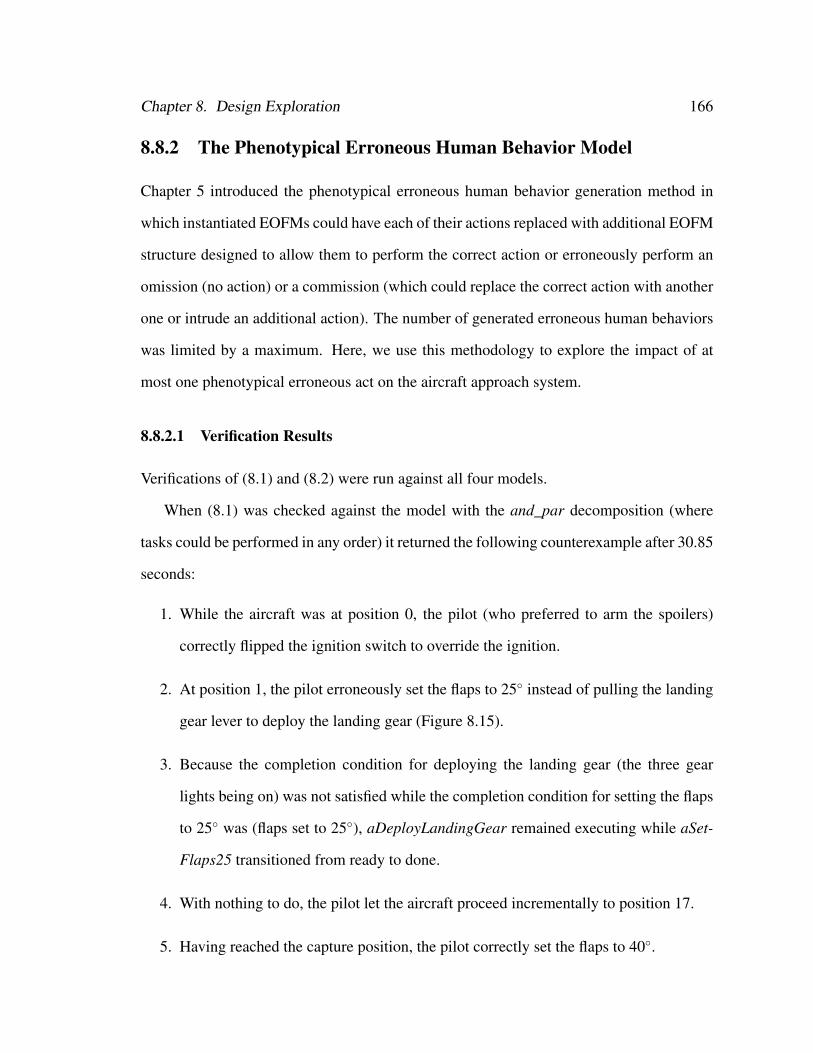
Chapter 8. Design Exploration 166
8.8.2 The Phenotypical Erroneous Human Behavior Model
Chapter 5 introduced the phenotypical erroneous human behavior generation method in
which instantiated EOFMs could have each of their actions replaced with additional EOFM
structure designed to allow them to perform the correct action or erroneously perform an
omission (no action) or a commission (which could replace the correct action with another
one or intrude an additional action). The number of generated erroneous human behaviors
was limited by a maximum. Here, we use this methodology to explore the impact of at
most one phenotypical erroneous act on the aircraft approach system.
8.8.2.1 Verification Results
Verifications of (8.1) and (8.2) were run against all four models.
When (8.1) was checked against the model with the and_par decomposition (where
tasks could be performed in any order) it returned the following counterexample after 30.85
seconds:
1. While the aircraft was at position 0, the pilot (who preferred to arm the spoilers)
correctly flipped the ignition switch to override the ignition.
2. At position 1, the pilot erroneously set the flaps to 25◦ instead of pulling the landing
gear lever to deploy the landing gear (Figure 8.15).
3. Because the completion condition for deploying the landing gear (the three gear
lights being on) was not satisfied while the completion condition for setting the flaps
to 25◦ was (flaps set to 25◦), aDeployLandingGear remained executing while aSet-
Flaps25 transitioned from ready to done.
4. With nothing to do, the pilot let the aircraft proceed incrementally to position 17.
5. Having reached the capture position, the pilot correctly set the flaps to 40◦.
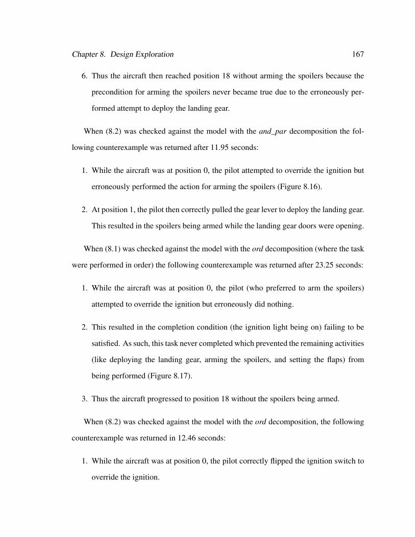
Chapter 8. Design Exploration 167
6. Thus the aircraft then reached position 18 without arming the spoilers because the
precondition for arming the spoilers never became true due to the erroneously per-
formed attempt to deploy the landing gear.
When (8.2) was checked against the model with the and_par decomposition the fol-
lowing counterexample was returned after 11.95 seconds:
1. While the aircraft was at position 0, the pilot attempted to override the ignition but
erroneously performed the action for arming the spoilers (Figure 8.16).
2. At position 1, the pilot then correctly pulled the gear lever to deploy the landing gear.
This resulted in the spoilers being armed while the landing gear doors were opening.
When (8.1) was checked against the model with the ord decomposition (where the task
were performed in order) the following counterexample was returned after 23.25 seconds:
1. While the aircraft was at position 0, the pilot (who preferred to arm the spoilers)
attempted to override the ignition but erroneously did nothing.
2. This resulted in the completion condition (the ignition light being on) failing to be
satisfied. As such, this task never completed which prevented the remaining activities
(like deploying the landing gear, arming the spoilers, and setting the flaps) from
being performed (Figure 8.17).
3. Thus the aircraft progressed to position 18 without the spoilers being armed.
When (8.2) was checked against the model with the ord decomposition, the following
counterexample was returned in 12.46 seconds:
1. While the aircraft was at position 0, the pilot correctly flipped the ignition switch to
override the ignition.
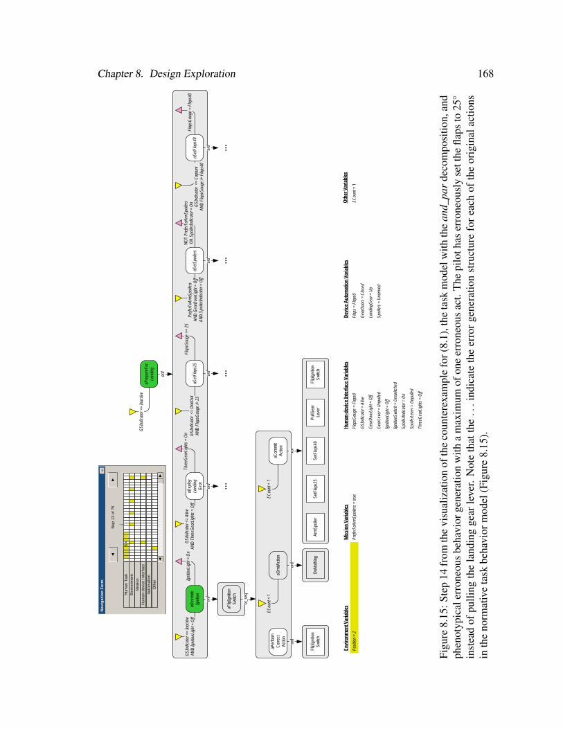
Chapter 8. Design Exploration 168
Oth
er V
aria
bles
aPre
pare
For
Land
ing
GSI
ndic
ator
<=
Inac
tive
ord
aOve
rride
Igni
tion
GSI
ndic
ator
<=
Inac
tive
AND
Igni
tionL
ight
= O
ffIg
nitio
nLig
ht =
On
ord
aDep
loy
Land
ing
Gea
r
GSI
ndic
ator
<=
Aliv
eAN
D T
hree
Gea
rLig
hts
= O
ff
Thre
eGea
rLig
hts
= O
n
...ord
aSet
Flap
s25
GSI
ndic
ator
<=
One
Dot
AND
Fla
psG
auge
/= 2
5
...ord
aSet
Spoi
lers
Pref
erTo
Arm
Spoi
lers
AN
D G
earD
oorL
ight
= O
ff AN
D S
poile
rIndi
cato
r = O
ff
NO
T Pr
efer
ToAr
mSp
oile
rsO
R S
poile
rIndi
cato
r = O
n
...ord
aSet
Flap
s40
GSI
ndic
ator
<=
Cap
ture
AND
Fla
psG
auge
/= F
laps
40
Flap
sGau
ge =
Fla
ps40
...ord
Flap
sGau
ge >
= 25
Envi
ronm
ent V
aria
bles
Posi
tion
= 2
Mis
sion
Var
iabl
es
Pref
erTo
Arm
Spoi
lers
= tr
ue
Hum
an-d
evic
e In
terf
ace
Varia
bles
Flap
sGau
ge =
Fla
ps0
GSI
ndic
ator
= A
live
Gea
rDoo
rLig
ht =
Off
Gea
rLev
er =
Unp
ulle
d
Igni
tionL
ight
= O
ff
Igni
tionS
witc
h =
Uns
witc
hed
Spoi
lerIn
dica
tor =
On
Spoi
lerL
ever
= U
npul
led
Thre
eGea
rLig
hts
= O
ff
Dev
ice
Aut
omat
ion
Varia
bles
Flap
s =
Flap
s0
Gea
rDoo
rs =
Clo
sed
Land
ingG
ear =
Up
Spoi
lers
= U
narm
ed
Step
13
of 7
6
↓
◄
Nav
igat
ion
Form
►
×
Hum
an T
ask
Envi
ronm
ent
Mis
sion
Hum
an-d
evic
e In
terf
ace
Auto
mat
ion
XX
►◄
Oth
er
aFlip
Igni
tion
Switc
h
or_s
eq
aPer
form
Cor
rect
Actio
n
ord
Flip
Igni
tion
Switc
h
aOm
itAct
ion
ECou
nt<
1
ord
DoN
othi
ng
aCom
mit
Actio
n
ECou
nt<
1
xor
Arm
Spoi
ler
SetF
laps
25Se
tFla
ps40
PullG
ear
Leve
rFl
ipIg
nitio
nSw
itch
ECou
nt=
1
Figu
re8.
15:S
tep
14fr
omth
evi
sual
izat
ion
ofth
eco
unte
rexa
mpl
efo
r(8.
1),t
heta
skm
odel
with
the
and_
par
deco
mpo
sitio
n,an
dph
enot
ypic
aler
rone
ous
beha
vior
gene
ratio
nw
itha
max
imum
ofon
eer
rone
ous
act.
The
pilo
thas
erro
neou
sly
sett
hefla
psto
25◦
inst
ead
ofpu
lling
the
land
ing
gear
leve
r.N
ote
that
the...
indi
cate
the
erro
rgen
erat
ion
stru
ctur
efo
reac
hof
the
orig
inal
actio
nsin
the
norm
ativ
eta
skbe
havi
orm
odel
(Fig
ure
8.15
).
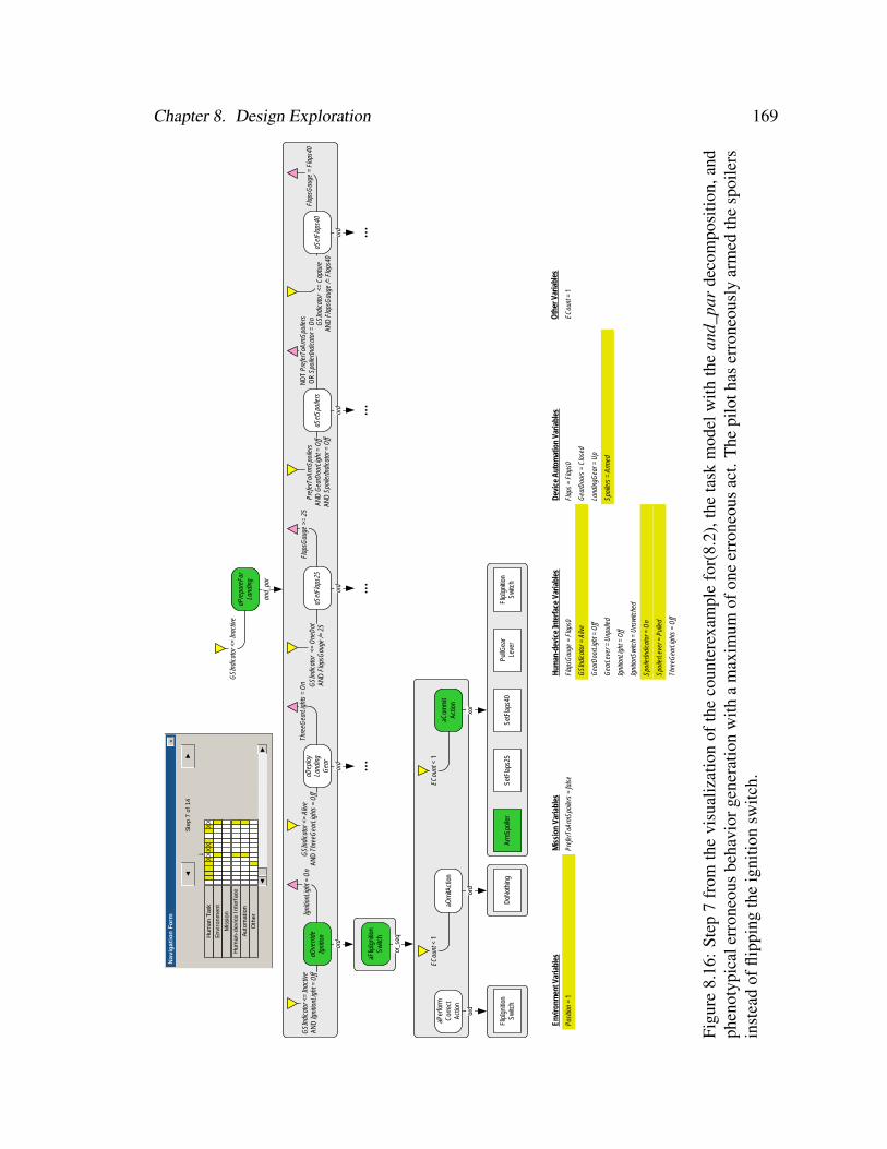
Chapter 8. Design Exploration 169
Oth
er V
aria
bles
aPre
pare
For
Land
ing
GSI
ndic
ator
<=
Inac
tive
and_
par
aOve
rride
Igni
tion
GSI
ndic
ator
<=
Inac
tive
AND
Igni
tionL
ight
= O
ffIg
nitio
nLig
ht =
On
ord
aDep
loy
Land
ing
Gea
r
GSI
ndic
ator
<=
Aliv
eAN
D T
hree
Gea
rLig
hts
= O
ff
Thre
eGea
rLig
hts
= O
n
...ord
aSet
Flap
s25
GSI
ndic
ator
<=
One
Dot
AND
Fla
psG
auge
/= 2
5
...ord
aSet
Spoi
lers
Pref
erTo
Arm
Spoi
lers
AN
D G
earD
oorL
ight
= O
ff AN
D S
poile
rIndi
cato
r = O
ff
NO
T Pr
efer
ToAr
mSp
oile
rsO
R S
poile
rIndi
cato
r = O
n
...ord
aSet
Flap
s40
GSI
ndic
ator
<=
Cap
ture
AND
Fla
psG
auge
/= F
laps
40
Flap
sGau
ge =
Fla
ps40
...ord
Flap
sGau
ge >
= 25
Envi
ronm
ent V
aria
bles
Posi
tion
= 1
Mis
sion
Var
iabl
es
Pref
erTo
Arm
Spoi
lers
= fa
lse
Hum
an-d
evic
e In
terf
ace
Varia
bles
Flap
sGau
ge =
Fla
ps0
GSI
ndic
ator
= A
live
Gea
rDoo
rLig
ht =
Off
Gea
rLev
er =
Unp
ulle
d
Igni
tionL
ight
= O
ff
Igni
tionS
witc
h =
Uns
witc
hed
Spoi
lerIn
dica
tor =
On
Spoi
lerL
ever
= P
ulle
d
Thre
eGea
rLig
hts
= O
ff
Dev
ice
Aut
omat
ion
Varia
bles
Flap
s =
Flap
s0
Gea
rDoo
rs =
Clo
sed
Land
ingG
ear =
Up
Spoi
lers
= A
rmed
Step
7 o
f 14
↓
◄
Nav
igat
ion
Form
►
×
Hum
an T
ask
Envi
ronm
ent
Mis
sion
Hum
an-d
evic
e In
terf
ace
Auto
mat
ion
XX
XX
►◄
Oth
er
aFlip
Igni
tion
Switc
h
or_s
eq
aPer
form
Cor
rect
Actio
n
ord
Flip
Igni
tion
Switc
h
aOm
itAct
ion
ECou
nt<
1
ord
DoN
othi
ng
aCom
mit
Actio
n
ECou
nt<
1
xor
Arm
Spoi
ler
SetF
laps
25Se
tFla
ps40
PullG
ear
Leve
rFl
ipIg
nitio
nSw
itch
XX
ECou
nt=
1
Figu
re8.
16:
Step
7fr
omth
evi
sual
izat
ion
ofth
eco
unte
rexa
mpl
efo
r(8.
2),t
heta
skm
odel
with
the
and_
par
deco
mpo
sitio
n,an
dph
enot
ypic
aler
rone
ous
beha
vior
gene
ratio
nw
itha
max
imum
ofon
eer
rone
ous
act.
The
pilo
thas
erro
neou
sly
arm
edth
esp
oile
rsin
stea
dof
flipp
ing
the
igni
tion
switc
h.

Chapter 8. Design Exploration 170
Oth
er V
aria
bles
aPre
pare
For
Land
ing
GSI
ndic
ator
<=
Inac
tive
ord
aOve
rride
Igni
tion
GSI
ndic
ator
<=
Inac
tive
AND
Igni
tionL
ight
= O
ffIg
nitio
nLig
ht =
On
ord
aDep
loy
Land
ing
Gea
r
GSI
ndic
ator
<=
Aliv
eAN
D T
hree
Gea
rLig
hts
= O
ff
Thre
eGea
rLig
hts
= O
n
...ord
aSet
Flap
s25
GSI
ndic
ator
<=
One
Dot
AND
Fla
psG
auge
/= 2
5
...ord
aSet
Spoi
lers
Pref
erTo
Arm
Spoi
lers
AN
D G
earD
oorL
ight
= O
ff AN
D S
poile
rIndi
cato
r = O
ff
NO
T Pr
efer
ToAr
mSp
oile
rsO
R S
poile
rIndi
cato
r = O
n
...ord
aSet
Flap
s40
GSI
ndic
ator
<=
Cap
ture
AND
Fla
psG
auge
/= F
laps
40
Flap
sGau
ge =
Fla
ps40
...ord
Flap
sGau
ge >
= 25
Envi
ronm
ent V
aria
bles
Posi
tion
= 2
Mis
sion
Var
iabl
es
Pref
erTo
Arm
Spoi
lers
= tr
ue
Hum
an-d
evic
e In
terf
ace
Varia
bles
Flap
sGau
ge =
Fla
ps0
GSI
ndic
ator
= A
live
Gea
rDoo
rLig
ht =
Off
Gea
rLev
er =
Unp
ulle
d
Igni
tionL
ight
= O
ff
Igni
tionS
witc
h =
Uns
witc
hed
Spoi
lerIn
dica
tor =
On
Spoi
lerL
ever
= U
npul
led
Thre
eGea
rLig
hts
= O
ff
Dev
ice
Aut
omat
ion
Varia
bles
Flap
s =
Flap
s0
Gea
rDoo
rs =
Clo
sed
Land
ingG
ear =
Up
Spoi
lers
= U
narm
ed
Step
13
of 7
6
↓
◄
Nav
igat
ion
Form
►
×
Hum
an T
ask
Envi
ronm
ent
Mis
sion
Hum
an-d
evic
e In
terf
ace
Auto
mat
ion
XX
►◄
Oth
er
aFlip
Igni
tion
Switc
h
or_s
eq
aPer
form
Cor
rect
Actio
n
ord
Flip
Igni
tion
Switc
h
aOm
itAct
ion
ECou
nt<
1
ord
DoN
othi
ng
aCom
mit
Actio
n
ECou
nt<
1
xor
Arm
Spoi
ler
SetF
laps
25Se
tFla
ps40
PullG
ear
Leve
rFl
ipIg
nitio
nSw
itch
ECou
nt=
1
Figu
re8.
17:
Step
17fr
omth
evi
sual
izat
ion
ofth
eco
unte
rexa
mpl
efo
r(8
.1),
the
task
mod
elw
ithth
eor
dde
com
posi
tion,
and
phen
otyp
ical
erro
neou
sbe
havi
orge
nera
tion
with
am
axim
umof
one
erro
neou
sac
t.T
hepi
loth
aspr
evio
usly
erro
neou
sly
done
noth
ing
inst
ead
offli
ppin
gth
esw
itch
toar
mth
esp
oile
rs.B
ecau
seth
eco
mpl
etio
nco
nditi
onfo
raO
verr
ideI
gniti
onha
sno
tbee
nsa
tisfie
d,no
furt
her
hum
anac
tions
can
bepe
rfor
med
.N
ote
that
the...
indi
cate
the
erro
rge
nera
tion
stru
ctur
efo
rea
chof
the
orig
inal
actio
nsin
the
norm
ativ
eta
skbe
havi
orm
odel
(Fig
ure
8.12
).
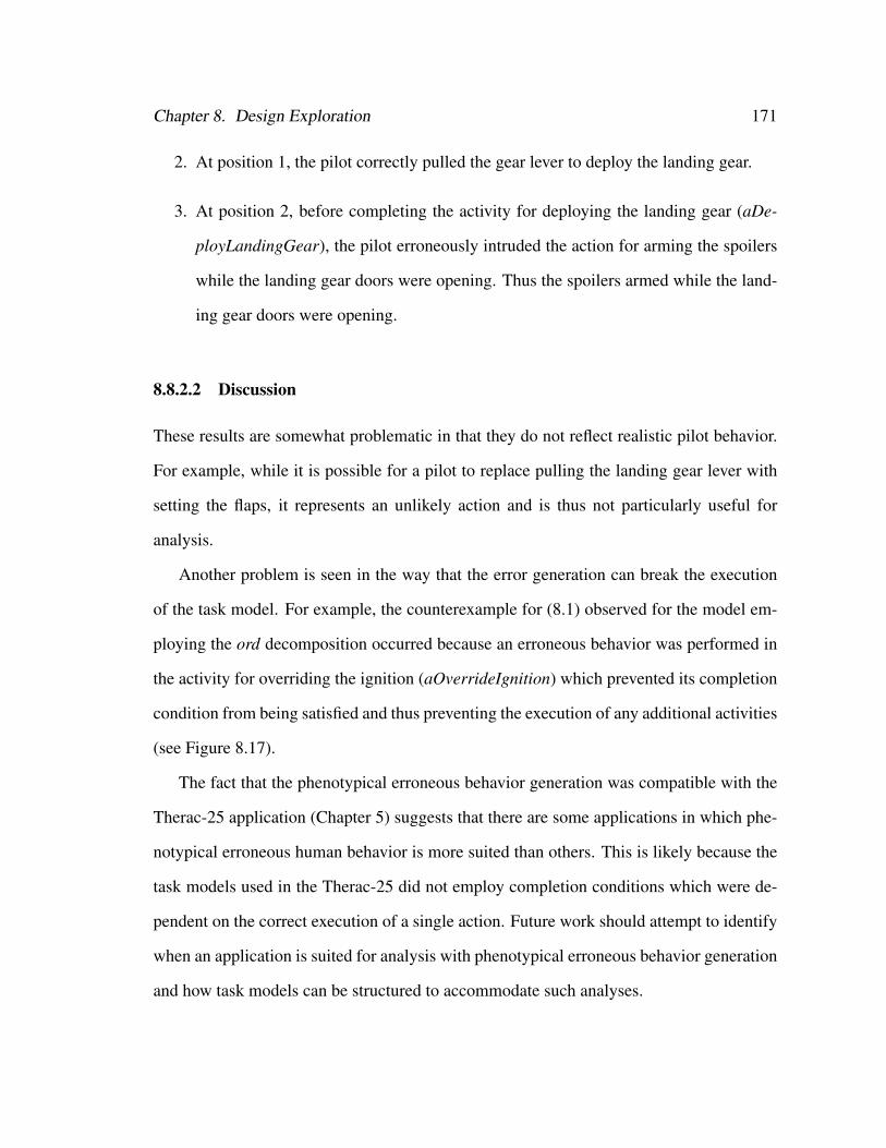
Chapter 8. Design Exploration 171
2. At position 1, the pilot correctly pulled the gear lever to deploy the landing gear.
3. At position 2, before completing the activity for deploying the landing gear (aDe-
ployLandingGear), the pilot erroneously intruded the action for arming the spoilers
while the landing gear doors were opening. Thus the spoilers armed while the land-
ing gear doors were opening.
8.8.2.2 Discussion
These results are somewhat problematic in that they do not reflect realistic pilot behavior.
For example, while it is possible for a pilot to replace pulling the landing gear lever with
setting the flaps, it represents an unlikely action and is thus not particularly useful for
analysis.
Another problem is seen in the way that the error generation can break the execution
of the task model. For example, the counterexample for (8.1) observed for the model em-
ploying the ord decomposition occurred because an erroneous behavior was performed in
the activity for overriding the ignition (aOverrideIgnition) which prevented its completion
condition from being satisfied and thus preventing the execution of any additional activities
(see Figure 8.17).
The fact that the phenotypical erroneous behavior generation was compatible with the
Therac-25 application (Chapter 5) suggests that there are some applications in which phe-
notypical erroneous human behavior is more suited than others. This is likely because the
task models used in the Therac-25 did not employ completion conditions which were de-
pendent on the correct execution of a single action. Future work should attempt to identify
when an application is suited for analysis with phenotypical erroneous behavior generation
and how task models can be structured to accommodate such analyses.
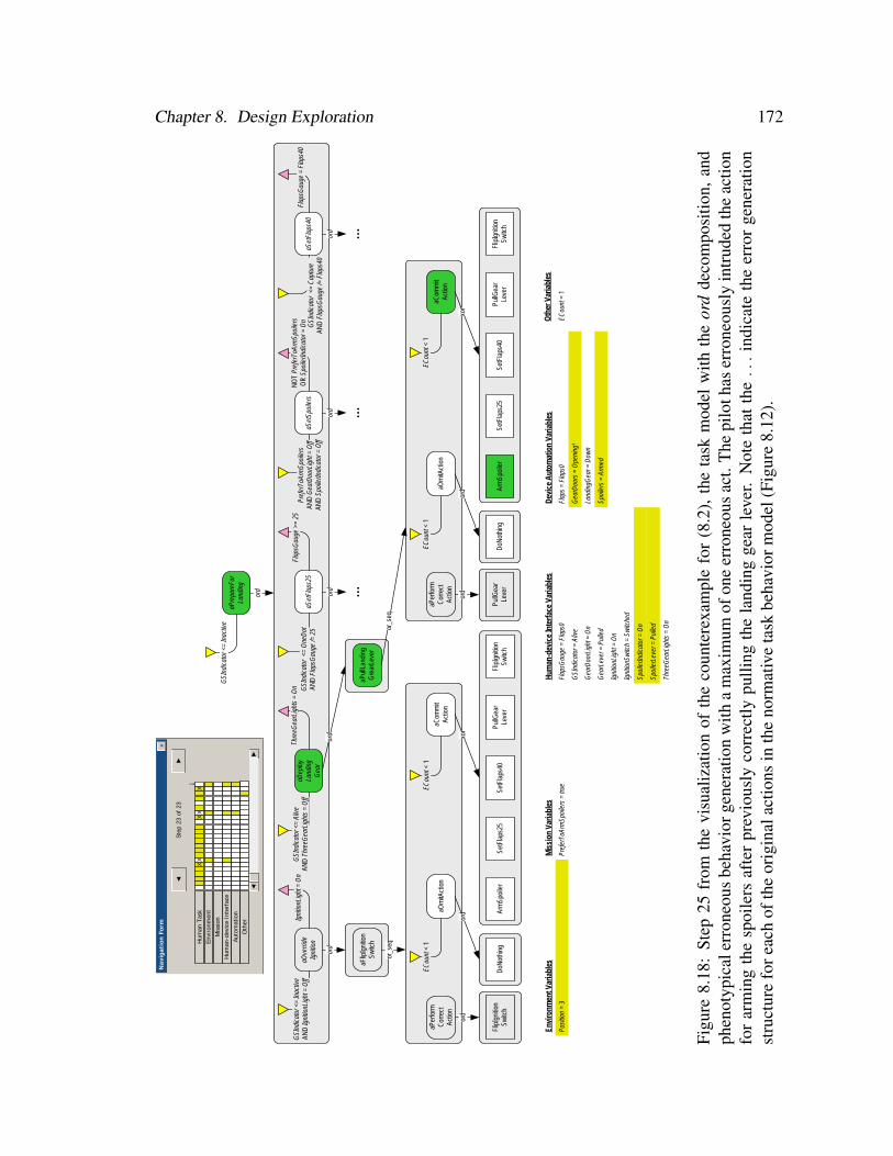
Chapter 8. Design Exploration 172
Oth
er V
aria
bles
aPre
pare
For
Land
ing
GSI
ndic
ator
<=
Inac
tive
ord
aOve
rride
Igni
tion
GSI
ndic
ator
<=
Inac
tive
AND
Igni
tionL
ight
= O
ffIg
nitio
nLig
ht =
On
ord
aDep
loy
Land
ing
Gea
r
GSI
ndic
ator
<=
Aliv
eAN
D T
hree
Gea
rLig
hts
= O
ff
Thre
eGea
rLig
hts
= O
n
...
ord
aSet
Flap
s25
GSI
ndic
ator
<=
One
Dot
AND
Fla
psG
auge
/= 2
5
...ord
aSet
Spoi
lers
Pref
erTo
Arm
Spoi
lers
AN
D G
earD
oorL
ight
= O
ff AN
D S
poile
rIndi
cato
r = O
ff
NO
T Pr
efer
ToAr
mSp
oile
rsO
R S
poile
rIndi
cato
r = O
n
...ord
aSet
Flap
s40
GSI
ndic
ator
<=
Cap
ture
AND
Fla
psG
auge
/= F
laps
40
Flap
sGau
ge =
Fla
ps40
...ord
Flap
sGau
ge >
= 25
Envi
ronm
ent V
aria
bles
Posi
tion
= 3
Mis
sion
Var
iabl
es
Pref
erTo
Arm
Spoi
lers
= tr
ue
Hum
an-d
evic
e In
terf
ace
Varia
bles
Flap
sGau
ge =
Fla
ps0
GSI
ndic
ator
= A
live
Gea
rDoo
rLig
ht =
On
Gea
rLev
er =
Pul
led
Igni
tionL
ight
= O
n
Igni
tionS
witc
h =
Switc
hed
Spoi
lerIn
dica
tor =
On
Spoi
lerL
ever
= P
ulle
d
Thre
eGea
rLig
hts
= O
n
Dev
ice
Aut
omat
ion
Varia
bles
Flap
s =
Flap
s0
Gea
rDoo
rs =
Ope
ning
1
Land
ingG
ear =
Dow
n
Spoi
lers
= A
rmed
Step
23
of 2
3
↓
◄
Nav
igat
ion
Form
►
×
Hum
an T
ask
Envi
ronm
ent
Mis
sion
Hum
an-d
evic
e In
terf
ace
Auto
mat
ion
XX
►◄
Oth
er
aFlip
Igni
tion
Switc
h
or_s
eq
aPer
form
Cor
rect
Actio
n
ord
Flip
Igni
tion
Switc
h
aOm
itAct
ion
ECou
nt<
1
ord
DoN
othi
ng
aCom
mit
Actio
n
ECou
nt<
1
xor
Arm
Spoi
ler
SetF
laps
25Se
tFla
ps40
PullG
ear
Leve
rFl
ipIg
nitio
nSw
itch
ECou
nt=
1
aPul
lLan
ding
Gre
arLe
ver
or_s
eq
aPer
form
Cor
rect
Actio
n
ord
PullG
ear
Leve
r
aOm
itAct
ion
ECou
nt<
1
ord
DoN
othi
ng
aCom
mit
Actio
n
ECou
nt<
1
xor
Arm
Spoi
ler
SetF
laps
25Se
tFla
ps40
PullG
ear
Leve
rFl
ipIg
nitio
nSw
itch
XX
X
Figu
re8.
18:
Step
25fr
omth
evi
sual
izat
ion
ofth
eco
unte
rexa
mpl
efo
r(8
.2),
the
task
mod
elw
ithth
eor
dde
com
posi
tion,
and
phen
otyp
ical
erro
neou
sbe
havi
orge
nera
tion
with
am
axim
umof
one
erro
neou
sac
t.T
hepi
loth
aser
rone
ousl
yin
trud
edth
eac
tion
for
arm
ing
the
spoi
lers
afte
rpr
evio
usly
corr
ectly
pulli
ngth
ela
ndin
gge
arle
ver.
Not
eth
atth
e...
indi
cate
the
erro
rge
nera
tion
stru
ctur
efo
reac
hof
the
orig
inal
actio
nsin
the
norm
ativ
eta
skbe
havi
orm
odel
(Fig
ure
8.12
).
Chapter 8. Design Exploration 173
8.8.3 The Strategic Knowledge-based Erroneous Behavior Model
Chapter 6 introduced an erroneous behavior generation method in which activities could er-
roneously transition between execution states due to the misapplication of strategic knowl-
edge contained in pre, repeat, and completion conditions. This could allow activities to
be erroneously omitted, repeated, or committed. The number of erroneous transitions was
limited by a maximum. Here, we use this methodology to explore the impact of at most
one erroneous transition on the aircraft approach system.
8.8.3.1 Verification Results
When (8.1) was checked against the model with the and_par decomposition, the following
counterexample was returned after 2.01 seconds:
1. While the aircraft was at position 0, the pilot (who preferred to arm the spoilers)
correctly flipped the ignition switch to override the ignition.
2. At position 1, the pilot erroneously omitted the activity for deploying the landing
gear (aDeployLandingGear) due to an erroneous executing to done transition (Figure
8.19), thus preventing the landing gear from being deployed.
3. The pilot then let the aircraft fly to position 11 where, because the glideslope indica-
tor was at the one dot position, he correctly performed the action for setting the flaps
to 25◦.
4. Because the landing gear was never deployed, the precondition for arming the spoil-
ers never became true, thus the pilot let the aircraft proceed to position 17 without
performing any additional actions.
5. At position 17, the aircraft reached capture, thus the pilot correctly set the flaps to
40◦. The aircraft then proceeded to position 18.
Chapter 8. Design Exploration 174
6. Thus the aircraft reached position 18 without the spoilers being armed.
When (8.2) was checked against the model with the and_par decomposition, the fol-
lowing counterexample was returned after 0.86 seconds:
1. While the aircraft was at position 0, the pilot erroneously performed the activity for
arming the spoilers (Figure 8.20): an erroneous ready to executing transition.
2. At position 1, he pulled the landing gear lever to correctly deploy the landing gear.
This resulted in the spoilers being armed while the landing gear doors were opening.
When (8.1) was checked against the model with the ord decomposition, a counterex-
ample was returned in 1.79 seconds:
1. While the aircraft was at position 0, the pilot (who preferred to arm the spoilers)
correctly flipped the ignition switch to override the ignition.
2. At position 1, the pilot omitted the activity for deploying the landing gear (the re-
sult of aDeployLandingGear erroneously transitioning from executing to done), thus
preventing the landing gear from deploying (the same erroneous behavior shown in
Figure 8.19).
3. The pilot then lets the aircraft fly to position 11 where, because the glideslope indi-
cator was at the one dot position, he correctly performed the action for setting the
flaps to 25◦.
4. Because the landing gear was never deployed, the precondition for arming the spoil-
ers never became true, thus the pilot let the aircraft proceed to position 18 without
performing any additional actions.
5. Thus the aircraft reached position 18 without the spoilers being armed.
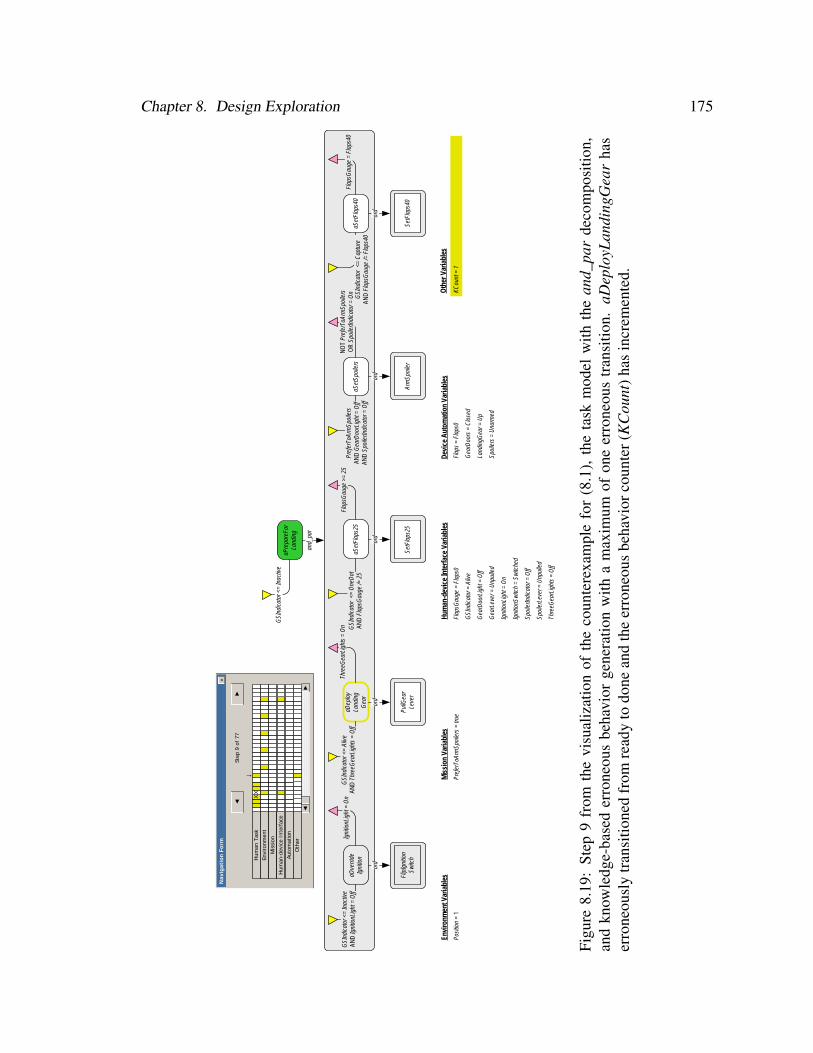
Chapter 8. Design Exploration 175
Oth
er V
aria
bles
aPre
pare
For
Land
ing
GSI
ndic
ator
<=
Inac
tive
and_
par
aOve
rride
Igni
tion
GSI
ndic
ator
<=
Inac
tive
AND
Igni
tionL
ight
= O
ffIg
nitio
nLig
ht =
On
ord
Flip
Igni
tion
Switc
h
aDep
loy
Land
ing
Gea
r
GSI
ndic
ator
<=
Aliv
eAN
D T
hree
Gea
rLig
hts
= O
ff
Thre
eGea
rLig
hts
= O
n
ord
PullG
ear
Leve
r
aSet
Flap
s25
GSI
ndic
ator
<=
One
Dot
AND
Fla
psG
auge
/= 2
5
ord
SetF
laps
25
aSet
Spoi
lers
Pref
erTo
Arm
Spoi
lers
AN
D G
earD
oorL
ight
= O
ff AN
D S
poile
rIndi
cato
r = O
ff
NO
T Pr
efer
ToAr
mSp
oile
rsO
R S
poile
rIndi
cato
r = O
n
ord
Arm
Spoi
ler
aSet
Flap
s40
GSI
ndic
ator
<=
Cap
ture
AND
Fla
psG
auge
/= F
laps
40
Flap
sGau
ge =
Fla
ps40
ord
SetF
laps
40
Flap
sGau
ge >
= 25
Envi
ronm
ent V
aria
bles
Posi
tion
= 1
Mis
sion
Var
iabl
es
Pref
erTo
Arm
Spoi
lers
= tr
ue
Hum
an-d
evic
e In
terf
ace
Varia
bles
Flap
sGau
ge =
Fla
ps0
GSI
ndic
ator
= A
live
Gea
rDoo
rLig
ht =
Off
Gea
rLev
er =
Unp
ulle
d
Igni
tionL
ight
= O
n
Igni
tionS
witc
h =
Switc
hed
Spoi
lerIn
dica
tor =
Off
Spoi
lerL
ever
= U
npul
led
Thre
eGea
rLig
hts
= O
ff
Dev
ice
Aut
omat
ion
Varia
bles
Flap
s =
Flap
s0
Gea
rDoo
rs =
Clo
sed
Land
ingG
ear =
Up
Spoi
lers
= U
narm
ed
Step
9 o
f 77
↓
◄
Nav
igat
ion
For
m
►
×
Hum
an T
ask
Envi
ronm
ent
Mis
sion
Hum
an-d
evic
e In
terf
ace
Auto
mat
ion
XX
►◄
Oth
er
KCou
nt =
1
Figu
re8.
19:
Step
9fr
omth
evi
sual
izat
ion
ofth
eco
unte
rexa
mpl
efo
r(8
.1),
the
task
mod
elw
ithth
ean
d_pa
rde
com
posi
tion,
and
know
ledg
e-ba
sed
erro
neou
sbe
havi
orge
nera
tion
with
am
axim
umof
one
erro
neou
str
ansi
tion.
aDep
loyL
andi
ngG
ear
has
erro
neou
sly
tran
sitio
ned
from
read
yto
done
and
the
erro
neou
sbe
havi
orco
unte
r(K
Cou
nt)h
asin
crem
ente
d.

Chapter 8. Design Exploration 176
Oth
er V
aria
bles
aPre
pare
For
Land
ing
GSI
ndic
ator
<=
Inac
tive
and_
par
aOve
rride
Igni
tion
GSI
ndic
ator
<=
Inac
tive
AND
Igni
tionL
ight
= O
ffIg
nitio
nLig
ht =
On
ord
Flip
Igni
tion
Switc
h
aDep
loy
Land
ing
Gea
r
GSI
ndic
ator
<=
Aliv
eAN
D T
hree
Gea
rLig
hts
= O
ff
Thre
eGea
rLig
hts
= O
n
ord
PullG
ear
Leve
r
aSet
Flap
s25
GSI
ndic
ator
<=
One
Dot
AND
Fla
psG
auge
/= 2
5
ord
SetF
laps
25
aSet
Spoi
lers
Pref
erTo
Arm
Spoi
lers
AN
D G
earD
oorL
ight
= O
ff AN
D S
poile
rIndi
cato
r = O
ff
NO
T Pr
efer
ToAr
mSp
oile
rsO
R S
poile
rIndi
cato
r = O
n
ord
Arm
Spoi
ler
aSet
Flap
s40
GSI
ndic
ator
<=
Cap
ture
AND
Fla
psG
auge
/= F
laps
40
Flap
sGau
ge =
Fla
ps40
ord
SetF
laps
40
Flap
sGau
ge >
= 25
Envi
ronm
ent V
aria
bles
Posi
tion
= 1
Mis
sion
Var
iabl
es
Pref
erTo
Arm
Spoi
lers
= tr
ue
Hum
an-d
evic
e In
terf
ace
Varia
bles
Flap
sGau
ge =
Fla
ps0
GSI
ndic
ator
= A
live
Gea
rDoo
rLig
ht =
Off
Gea
rLev
er =
Unp
ulle
d
Igni
tionL
ight
= O
n
Igni
tionS
witc
h =
Switc
hed
Spoi
lerIn
dica
tor =
On
Spoi
lerL
ever
= P
ulle
d
Thre
eGea
rLig
hts
= O
ff
Dev
ice
Aut
omat
ion
Varia
bles
Flap
s =
Flap
s0
Gea
rDoo
rs =
Clo
sed
Land
ingG
ear =
Up
Spoi
lers
= A
rmed
Step
5 o
f 10
↓
◄
Nav
igat
ion
For
m
►
×
Hum
an T
ask
Envi
ronm
ent
Mis
sion
Hum
an-d
evic
e In
terf
ace
Auto
mat
ion
XX
►◄
Oth
er
KCou
nt =
1
Figu
re8.
20:
Step
5fr
omth
evi
sual
izat
ion
ofth
eco
unte
rexa
mpl
efo
r(8.
2),t
heta
skm
odel
with
the
and_
par
deco
mpo
sitio
nan
dkn
owle
dge-
base
der
rone
ous
beha
vior
gene
ratio
nw
itha
max
imum
ofon
eer
rone
ous
tran
sitio
n.aS
etSp
oile
rsha
sju
stpr
evio
usly
erro
neou
sly
tran
sitio
ned
from
read
yto
exec
utin
g(i
ncre
men
ting
KC
ount
)w
hich
has
resu
lted
inth
esp
oile
rsbe
ing
arm
edbe
fore
any
othe
ract
iviti
esoc
cur.
Chapter 8. Design Exploration 177
When (8.2) was checked against the model with the ord decomposition, it verified to
true in 1.51 seconds having visited 926 states.
8.8.3.2 Additional Verification Results
It is unlikely that pilots will not deploy the landing gear, the source of the problems found
when the models were checked against (8.1). As such, the counterexamples associated with
these verifications could be considered artifacts of our formal system models. To allow for
the possibility of discovering more realistic system failures, these artifacts were eliminated
by removing the erroneous executing to done transition of aDeployLandingGear (the tran-
sition associated with the failure to deploy the landing gear) from the models using the
method discussed in Chapter 6. The following are the results of (8.1) being checked against
these modified models.
When (8.1) was checked against the modified model with the and_par decomposition,
the following counterexample was returned after 2.01 seconds:
1. While the aircraft was at position 0, the pilot (who prefers to arm the spoilers) cor-
rectly flipped the ignition switch to override the ignition.
2. At position 1, the pilot correctly performed the action for deploying the landing gear,
deploying the landing gear and initiating the opening of the landing gear doors.
3. The aircraft proceeded along its path until position 11 where the landing gear doors
become completely open.
4. At position 11, because the glideslope indicator was at the one dot position, the pilot
correctly performed the action for setting the flaps to 25◦.
5. At position 12, the activity for setting the spoilers was omitted (aSetSpoilers erro-
neously transitioned from ready to done).
Chapter 8. Design Exploration 178
6. At position 17, the aircraft reached the capture position and thus the pilot set the
flaps to 40◦.
7. The aircraft then proceeded to position 18 without the spoilers being armed.
When (8.1) was checked against the model with the ord decomposition it verified to
true in 1.49 seconds having visited 752 states.
8.8.4 Discussion
The analyses show that the task model with the ord decomposition is more resistant to
failures than the model with the and_par decomposition. These results suggest that, if
airlines can enforce a strict adherence to the behavior represented by the model with the
ord decomposition, they may be less likely to experience problems related to premature
spoiler deployment and failure to arm spoilers. This work could be followed up with
additional studies, possibly with real pilots in actual operating conditions, to determine if
this is true.
Should analysts or designers wish to address the problems discovered with the and_par
task behavior model, they could pursue some of the options addressed in the discussion of
Phase 1: eliminating spoiler arming as an option (in the mission) and preventing spoiler
arming before the landing gear doors are completely open. Future work should explore
these potential solutions.
While the phenotypical erroneous human behavior generation method did not facilitate
many insights into human-automation interaction for this application, strategic knowledge-
based erroneous human behavior generation has. This suggests that there may be some
applications better suited to each erroneous behavior generation method. Future work
should attempt to identify properties of applications that suggest analysis with the different
erroneous behavior generation methods.
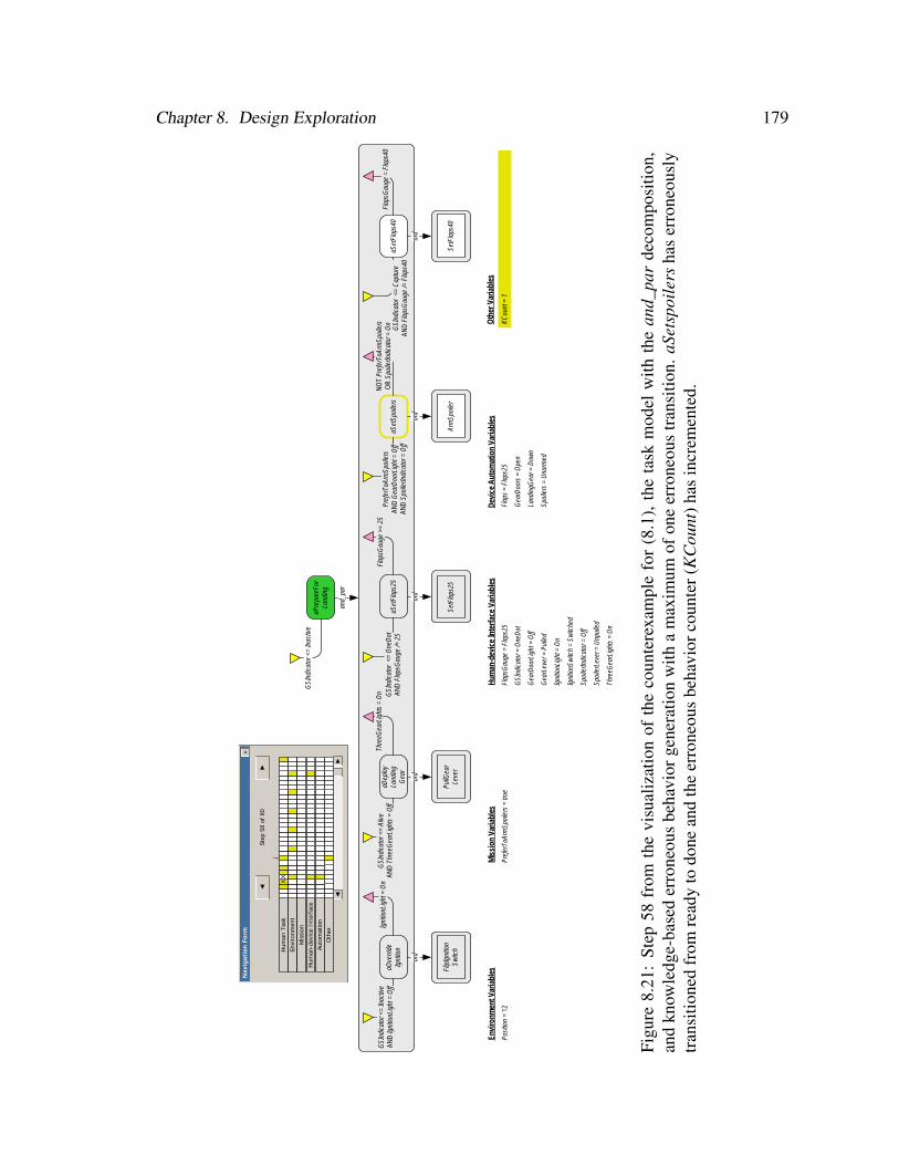
Chapter 8. Design Exploration 179
Oth
er V
aria
bles
aPre
pare
For
Land
ing
GSI
ndic
ator
<=
Inac
tive
and_
par
aOve
rride
Igni
tion
GSI
ndic
ator
<=
Inac
tive
AND
Igni
tionL
ight
= O
ffIg
nitio
nLig
ht =
On
ord
Flip
Igni
tion
Switc
h
aDep
loy
Land
ing
Gea
r
GSI
ndic
ator
<=
Aliv
eAN
D T
hree
Gea
rLig
hts
= O
ff
Thre
eGea
rLig
hts
= O
n
ord
PullG
ear
Leve
r
aSet
Flap
s25
GSI
ndic
ator
<=
One
Dot
AND
Fla
psG
auge
/= 2
5
ord
SetF
laps
25
aSet
Spoi
lers
Pref
erTo
Arm
Spoi
lers
AN
D G
earD
oorL
ight
= O
ff AN
D S
poile
rIndi
cato
r = O
ff
NO
T Pr
efer
ToAr
mSp
oile
rsO
R S
poile
rIndi
cato
r = O
n
ord
Arm
Spoi
ler
aSet
Flap
s40
GSI
ndic
ator
<=
Cap
ture
AND
Fla
psG
auge
/= F
laps
40
Flap
sGau
ge =
Fla
ps40
ord
SetF
laps
40
Flap
sGau
ge >
= 25
Envi
ronm
ent V
aria
bles
Posi
tion
= 12
Mis
sion
Var
iabl
es
Pref
erTo
Arm
Spoi
lers
= tr
ue
Hum
an-d
evic
e In
terf
ace
Varia
bles
Flap
sGau
ge =
Fla
ps25
GSI
ndic
ator
= O
neD
ot
Gea
rDoo
rLig
ht =
Off
Gea
rLev
er =
Pul
led
Igni
tionL
ight
= O
n
Igni
tionS
witc
h =
Switc
hed
Spoi
lerIn
dica
tor =
Off
Spoi
lerL
ever
= U
npul
led
Thre
eGea
rLig
hts
= O
n
Dev
ice
Aut
omat
ion
Varia
bles
Flap
s =
Flap
s25
Gea
rDoo
rs =
Ope
n
Land
ingG
ear =
Dow
n
Spoi
lers
= U
narm
ed
Step
58
of 8
0
↓
◄
Nav
igat
ion
For
m
►
×
Hum
an T
ask
Envi
ronm
ent
Mis
sion
Hum
an-d
evic
e In
terf
ace
Auto
mat
ion
XX
►◄
Oth
er
KCou
nt =
1
Figu
re8.
21:
Step
58fr
omth
evi
sual
izat
ion
ofth
eco
unte
rexa
mpl
efo
r(8
.1),
the
task
mod
elw
ithth
ean
d_pa
rde
com
posi
tion,
and
know
ledg
e-ba
sed
erro
neou
sbe
havi
orge
nera
tion
with
am
axim
umof
one
erro
neou
str
ansi
tion.
aSet
spoi
lers
has
erro
neou
sly
tran
sitio
ned
from
read
yto
done
and
the
erro
neou
sbe
havi
orco
unte
r(K
Cou
nt)h
asin
crem
ente
d.
Chapter 8. Design Exploration 180
8.9 Phase 3 Analyses: Exploring Variations in the Behav-
ior of the Automation
8.9.1 Modeling
In the third phase of modeling we show how our architecture can be used to explore how
variations in the behavior of automated systems can impact system safety properties.
Aside from the human operator, there can be anomalous conditions in device automa-
tion and/or the environment that can impact system performance. For example, aging me-
chanics in aircraft automation can impact overall system performance. For our purposes,
we are concerned with how the time delays associated with aging hydraulic systems may
influence human-automation interaction issues related to the deployment of spoilers.
For this phase of analysis, we assume that the aging hydraulic systems in the landing
gear doors openers can delay the door opening process by up to 7 seconds beyond the 10
seconds the doors took to open normatively (Figure 8.4). We can exploit the modularization
of our architecture to replace the previous device automation model with one in which the
landing gear opening can take between 0 and 7 additional seconds (in 1 second increments)
to open making the range of potential landing gear opening time between 10 and 17. All
other device automation models were kept the same, as were the mission and environment
model. These were used to create formal system models using the normative task behavior
model with the ord decomposition and one with the normative task behavior model with
the and_par decomposition (both using the corrected precondition discussed at the end of
Phase 1).
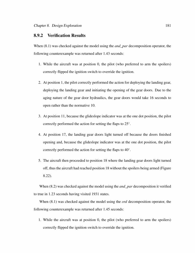
Chapter 8. Design Exploration 181
8.9.2 Verification Results
When (8.1) was checked against the model using the and_par decomposition operator, the
following counterexample was returned after 1.43 seconds:
1. While the aircraft was at position 0, the pilot (who preferred to arm the spoilers)
correctly flipped the ignition switch to override the ignition.
2. At position 1, the pilot correctly performed the action for deploying the landing gear,
deploying the landing gear and initiating the opening of the gear doors. Due to the
aging nature of the gear door hydraulics, the gear doors would take 16 seconds to
open rather than the normative 10.
3. At position 11, because the glideslope indicator was at the one dot position, the pilot
correctly performed the action for setting the flaps to 25◦.
4. At position 17, the landing gear doors light turned off because the doors finished
opening and, because the glideslope indicator was at the one dot position, the pilot
correctly performed the action for setting the flaps to 40◦.
5. The aircraft then proceeded to position 18 where the landing gear doors light turned
off, thus the aircraft had reached position 18 without the spoilers being armed (Figure
8.22).
When (8.2) was checked against the model using the and_par decomposition it verified
to true in 1.23 seconds having visited 1931 states.
When (8.1) was checked against the model using the ord decomposition operator, the
following counterexample was returned after 1.45 seconds:
1. While the aircraft was at position 0, the pilot (who preferred to arm the spoilers)
correctly flipped the ignition switch to override the ignition.

Chapter 8. Design Exploration 182
Oth
er V
aria
bles
aPre
pare
For
Land
ing
GSI
ndic
ator
<=
Inac
tive
and_
par
aOve
rride
Igni
tion
GSI
ndic
ator
<=
Inac
tive
AND
Igni
tionL
ight
= O
ffIg
nitio
nLig
ht =
On
ord
Flip
Igni
tion
Switc
h
aDep
loy
Land
ing
Gea
r
GSI
ndic
ator
<=
Aliv
eAN
D T
hree
Gea
rLig
hts
= O
ff
Thre
eGea
rLig
hts
= O
n
ord
PullG
ear
Leve
r
aSet
Flap
s25
GSI
ndic
ator
<=
One
Dot
AND
Fla
psG
auge
/= 2
5
ord
SetF
laps
25
aSet
Spoi
lers
Pref
erTo
Arm
Spoi
lers
AN
D G
earD
oorL
ight
= O
ff AN
D S
poile
rIndi
cato
r = O
ff
NO
T Pr
efer
ToAr
mSp
oile
rsO
R S
poile
rIndi
cato
r = O
n
ord
Arm
Spoi
ler
aSet
Flap
s40
GSI
ndic
ator
<=
Cap
ture
AND
Fla
psG
auge
/= F
laps
40
Flap
sGau
ge =
Fla
ps40
ord
SetF
laps
40
Flap
sGau
ge >
= 25
Envi
ronm
ent V
aria
bles
Posi
tion
= 18
Mis
sion
Var
iabl
es
Pref
erTo
Arm
Spoi
lers
= tr
ue
Hum
an-d
evic
e In
terf
ace
Varia
bles
Flap
sGau
ge =
Fla
ps40
GSI
ndic
ator
= C
aptu
re
Gea
rDoo
rLig
ht =
Off
Gea
rLev
er =
Pul
led
Igni
tionL
ight
= O
n
Igni
tionS
witc
h =
Switc
hed
Spoi
lerIn
dica
tor =
Off
Spoi
lerL
ever
= U
npul
led
Thre
eGea
rLig
hts
= O
n
Dev
ice
Aut
omat
ion
Varia
bles
Flap
s =
Flap
s40
Gea
rDoo
rs =
Ope
n
Land
ingG
ear =
Dow
n
Spoi
lers
= U
narm
ed
Step
78
of 7
8
↓
◄
Nav
igat
ion
Form
►
×
Hum
an T
ask
Envi
ronm
ent
Mis
sion
Hum
an-d
evic
e In
terf
ace
Auto
mat
ion
XX
►◄
Oth
er
XX
Extra
Gea
rTim
e =
0
Figu
re8.
22:
Step
78fr
omth
evi
sual
izat
ion
ofth
eco
unte
rexa
mpl
efo
rth
eta
skm
odel
with
the
and_
par
deco
mpo
sitio
nan
dan
auto
mat
ion
mod
elw
itha
vari
ably
degr
aded
land
ing
gear
door
hydr
aulic
syst
em.T
heai
rcra
ftha
sre
ache
dpo
sitio
n18
with
outt
hepi
lota
rmin
gth
esp
oile
rsdu
eto
the
land
ing
gear
door
sno
tcom
plet
ely
open
ing
until
posi
tion
17.
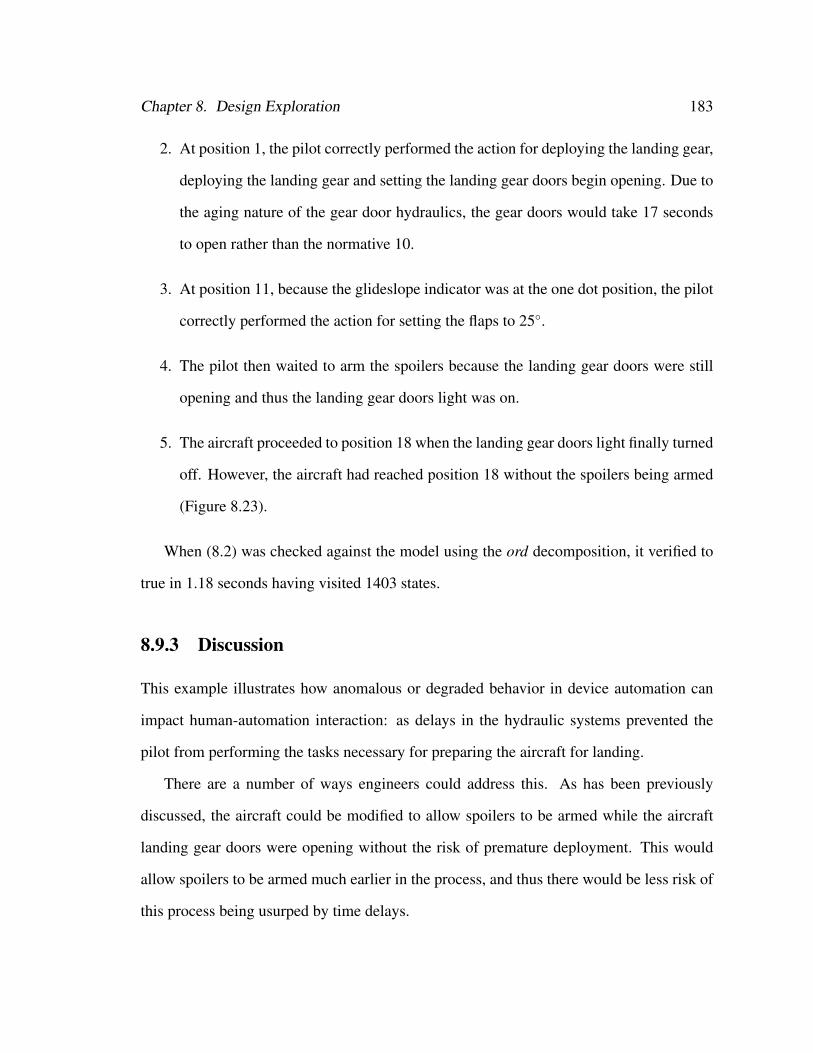
Chapter 8. Design Exploration 183
2. At position 1, the pilot correctly performed the action for deploying the landing gear,
deploying the landing gear and setting the landing gear doors begin opening. Due to
the aging nature of the gear door hydraulics, the gear doors would take 17 seconds
to open rather than the normative 10.
3. At position 11, because the glideslope indicator was at the one dot position, the pilot
correctly performed the action for setting the flaps to 25◦.
4. The pilot then waited to arm the spoilers because the landing gear doors were still
opening and thus the landing gear doors light was on.
5. The aircraft proceeded to position 18 when the landing gear doors light finally turned
off. However, the aircraft had reached position 18 without the spoilers being armed
(Figure 8.23).
When (8.2) was checked against the model using the ord decomposition, it verified to
true in 1.18 seconds having visited 1403 states.
8.9.3 Discussion
This example illustrates how anomalous or degraded behavior in device automation can
impact human-automation interaction: as delays in the hydraulic systems prevented the
pilot from performing the tasks necessary for preparing the aircraft for landing.
There are a number of ways engineers could address this. As has been previously
discussed, the aircraft could be modified to allow spoilers to be armed while the aircraft
landing gear doors were opening without the risk of premature deployment. This would
allow spoilers to be armed much earlier in the process, and thus there would be less risk of
this process being usurped by time delays.
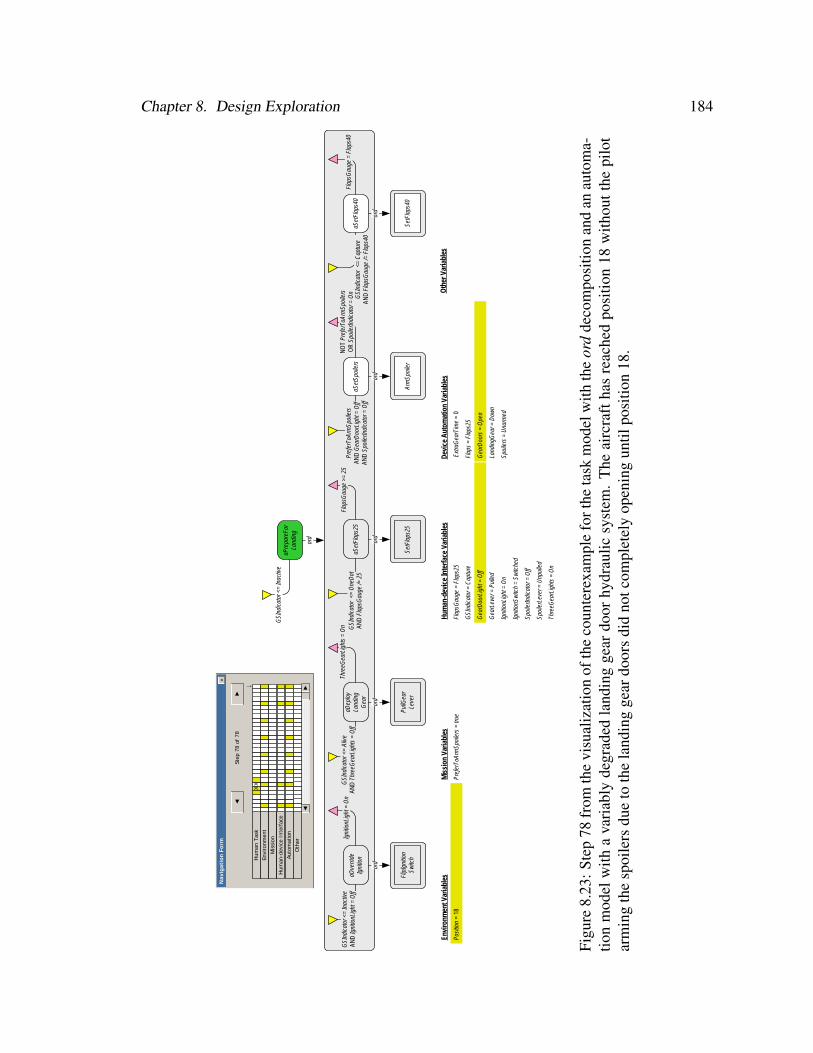
Chapter 8. Design Exploration 184
Oth
er V
aria
bles
aPre
pare
For
Land
ing
GSI
ndic
ator
<=
Inac
tive
ord
aOve
rride
Igni
tion
GSI
ndic
ator
<=
Inac
tive
AND
Igni
tionL
ight
= O
ffIg
nitio
nLig
ht =
On
ord
Flip
Igni
tion
Switc
h
aDep
loy
Land
ing
Gea
r
GSI
ndic
ator
<=
Aliv
eAN
D T
hree
Gea
rLig
hts
= O
ff
Thre
eGea
rLig
hts
= O
n
ord
PullG
ear
Leve
r
aSet
Flap
s25
GSI
ndic
ator
<=
One
Dot
AND
Fla
psG
auge
/= 2
5
ord
SetF
laps
25
aSet
Spoi
lers
Pref
erTo
Arm
Spoi
lers
AN
D G
earD
oorL
ight
= O
ff AN
D S
poile
rIndi
cato
r = O
ff
NO
T Pr
efer
ToAr
mSp
oile
rsO
R S
poile
rIndi
cato
r = O
n
ord
Arm
Spoi
ler
aSet
Flap
s40
GSI
ndic
ator
<=
Cap
ture
AND
Fla
psG
auge
/= F
laps
40
Flap
sGau
ge =
Fla
ps40
ord
SetF
laps
40
Flap
sGau
ge >
= 25
Envi
ronm
ent V
aria
bles
Posi
tion
= 18
Mis
sion
Var
iabl
es
Pref
erTo
Arm
Spoi
lers
= tr
ue
Hum
an-d
evic
e In
terf
ace
Varia
bles
Flap
sGau
ge =
Fla
ps25
GSI
ndic
ator
= C
aptu
re
Gea
rDoo
rLig
ht =
Off
Gea
rLev
er =
Pul
led
Igni
tionL
ight
= O
n
Igni
tionS
witc
h =
Switc
hed
Spoi
lerIn
dica
tor =
Off
Spoi
lerL
ever
= U
npul
led
Thre
eGea
rLig
hts
= O
n
Dev
ice
Aut
omat
ion
Varia
bles
Flap
s =
Flap
s25
Gea
rDoo
rs =
Ope
n
Land
ingG
ear =
Dow
n
Spoi
lers
= U
narm
ed
Step
78
of 7
8
↓
◄
Nav
igat
ion
For
m
►
×
Hum
an T
ask
Envi
ronm
ent
Mis
sion
Hum
an-d
evic
e In
terf
ace
Auto
mat
ion
XX
►◄
Oth
er
Extra
Gea
rTim
e =
0
Figu
re8.
23:S
tep
78fr
omth
evi
sual
izat
ion
ofth
eco
unte
rexa
mpl
efo
rthe
task
mod
elw
ithth
eor
dde
com
posi
tion
and
anau
tom
a-tio
nm
odel
with
ava
riab
lyde
grad
edla
ndin
gge
ardo
orhy
drau
licsy
stem
.T
heai
rcra
ftha
sre
ache
dpo
sitio
n18
with
outt
hepi
lot
arm
ing
the
spoi
lers
due
toth
ela
ndin
gge
ardo
ors
did
notc
ompl
etel
yop
enin
gun
tilpo
sitio
n18
.
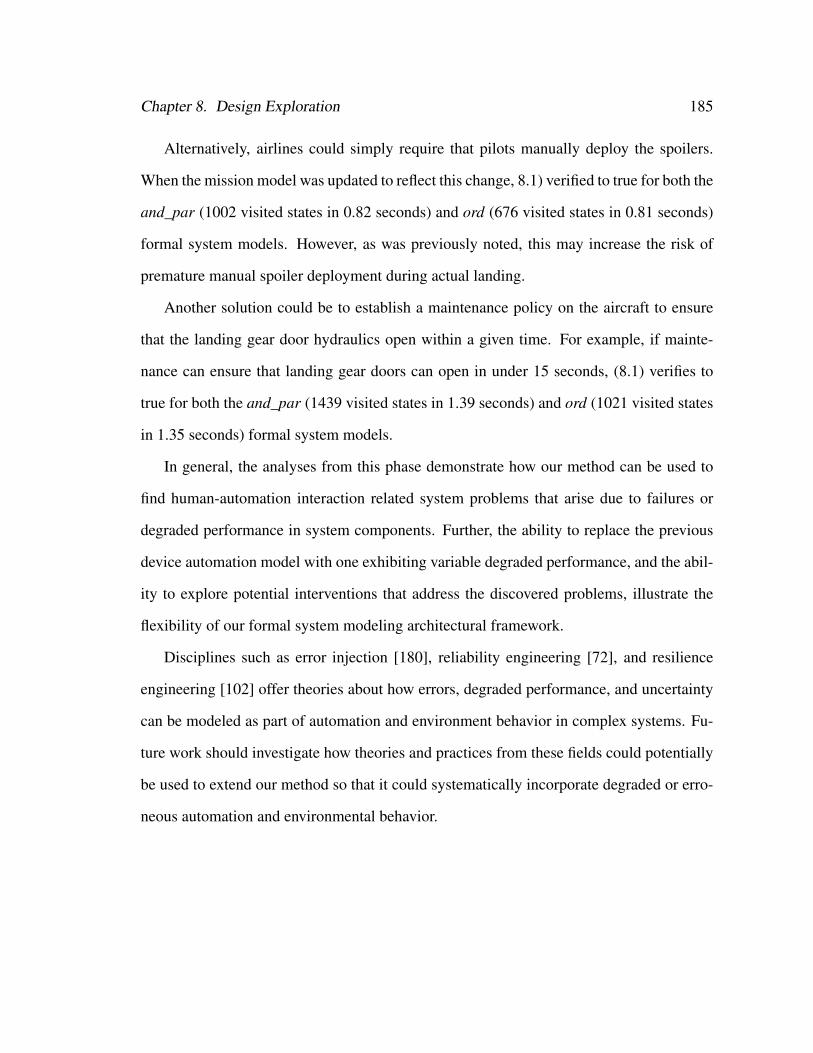
Chapter 8. Design Exploration 185
Alternatively, airlines could simply require that pilots manually deploy the spoilers.
When the mission model was updated to reflect this change, 8.1) verified to true for both the
and_par (1002 visited states in 0.82 seconds) and ord (676 visited states in 0.81 seconds)
formal system models. However, as was previously noted, this may increase the risk of
premature manual spoiler deployment during actual landing.
Another solution could be to establish a maintenance policy on the aircraft to ensure
that the landing gear door hydraulics open within a given time. For example, if mainte-
nance can ensure that landing gear doors can open in under 15 seconds, (8.1) verifies to
true for both the and_par (1439 visited states in 1.39 seconds) and ord (1021 visited states
in 1.35 seconds) formal system models.
In general, the analyses from this phase demonstrate how our method can be used to
find human-automation interaction related system problems that arise due to failures or
degraded performance in system components. Further, the ability to replace the previous
device automation model with one exhibiting variable degraded performance, and the abil-
ity to explore potential interventions that address the discovered problems, illustrate the
flexibility of our formal system modeling architectural framework.
Disciplines such as error injection [180], reliability engineering [72], and resilience
engineering [102] offer theories about how errors, degraded performance, and uncertainty
can be modeled as part of automation and environment behavior in complex systems. Fu-
ture work should investigate how theories and practices from these fields could potentially
be used to extend our method so that it could systematically incorporate degraded or erro-
neous automation and environmental behavior.
Chapter 8. Design Exploration 186
8.10 General Discussion
Although the example presented here is simplistic, our method was able to facilitate a
number of analyses which allowed the design of the aircraft approach system to be explored
in a variety of different capacities. The phase 1 analyses showed how different human task
behaviors could be used to explore a system design. The phase 2 analyses showed how the
different erroneous behavior generation processes could be used to find potential failures
associated with erroneous human behavior and how erroneous behaviors not pertinent to
the analyses could be removed. Phase 3 analyses showed how alternative models of the
device automation could be employed in analyses. Further, in all phases, the flexibility of
our formal modeling architecture was demonstrated in the way different normative human
task behaviors, erroneous human task behaviors, device automations, and human missions
were modified and incorporated into the formal system model in order to explore different
designs and interventions that addressed some of the discovered problems.
In a more realistic example, the application would likely be more complicated, and the
analyst may have many more specifications he would want to check against each design
variation. In such a circumstance, it is likely that the analyst may want to compare the re-
sults of different analyses in order to diagnose similar problems that exist between designs,
and to compare and contrast the performance of the designs. Future work should investi-
gate how additional tools and analyses might be incorporated into our method in order to
facilitate these sorts of comparative evaluations.
Chapter 9
Contributions and Future Work
This work has shown that it is possible to automatically incorporate erroneous human be-
havior into task analytic models for the purpose of formally verifying system safety prop-
erties in light of both normative and erroneous human behavior. This was done by using
our novel method to discover and evaluate problems with human-automation interactive
systems. Each of the different applications that were employed in the verification illus-
trated the different ways the method could be used, and the insights it could provide (Table
9.1).
Firstly, the applications demonstrate the flexibility of the formal modeling architecture
in that not all formal system models need to have every element of the architecture. While
the aircraft and and cruise control examples have models of every element of the architec-
ture, the PCA pump and radiation therapy machine applications did not have environment
models.
Alternatively, the nature of the human task is different between the modeled applica-
tions. For the PCA pump, the primary task was data driven in that it was primarily fulfilling
mission goals related to entering data into the automated system. In the other models, the
human tasks were procedural.
187
Chapter 9. Contributions and Future Work 188
Thirdly, the erroneous human behavior prediction was exploited differently in order
to show how problems with human-automation interaction could be discovered with our
method. In all of our applications, normative task models were used in formal verifica-
tions. For the aircraft and cruise control examples these verifications initially produced
counterexamples. However, changes to the formal system model resulted in models that
verified to true. The other application models verified to true with normative task behavior
models without modification.
Erroneous human behavior models were tested with all but the cruise control appli-
cation. Phenotypical erroneous behavior models were generated for the radiation therapy
machine and aircraft applications and used in formal verifications which found specifica-
tion violations. Knowledge-based erroneous behavior models were generated for the PCA
pump and aircraft applications and also produced specification violations when evaluated
as part of a formal system model. In all applications employing erroneous task behavior
models, changes were made to the formal system model and formal verification was per-
formed to ensure that the erroneous behavior would no longer contribute to specification
violations.
All of the counterexamples produced in the verifications of the different application’s
models were evaluated with the counterexample visualizer.
9.0.1 Specific Contributions
9.0.1.1 The EOFM Language
The EOFM language developed as part of this work is itself a contribution as it provides
a generic, platform independent means of modeling human task behavior. This language
supports a superset of the features supported by similar modeling paradigms such as OFM
[139], CTT [156], GOMS [110], and UAN [94] (see [28, 33] for a complete discussion of
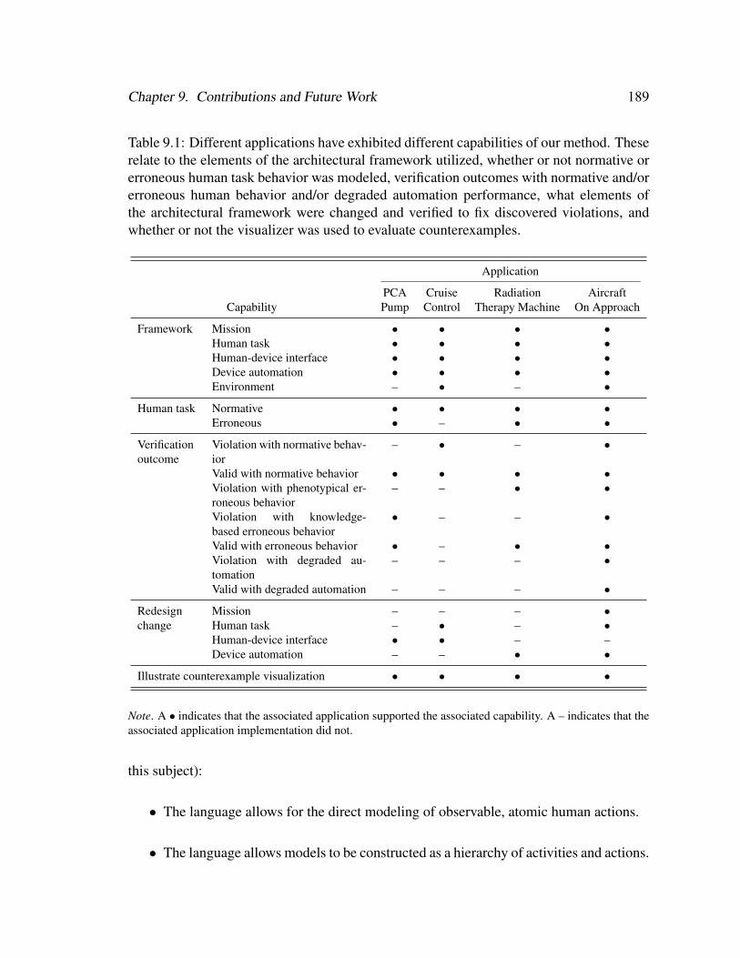
Chapter 9. Contributions and Future Work 189
Table 9.1: Different applications have exhibited different capabilities of our method. Theserelate to the elements of the architectural framework utilized, whether or not normative orerroneous human task behavior was modeled, verification outcomes with normative and/orerroneous human behavior and/or degraded automation performance, what elements ofthe architectural framework were changed and verified to fix discovered violations, andwhether or not the visualizer was used to evaluate counterexamples.
Application
PCA Cruise Radiation AircraftCapability Pump Control Therapy Machine On Approach
Framework Mission • • • •Human task • • • •Human-device interface • • • •Device automation • • • •Environment – • – •
Human task Normative • • • •Erroneous • – • •
Verificationoutcome
Violation with normative behav-ior
– • – •
Valid with normative behavior • • • •Violation with phenotypical er-roneous behavior
– – • •
Violation with knowledge-based erroneous behavior
• – – •
Valid with erroneous behavior • – • •Violation with degraded au-tomation
– – – •
Valid with degraded automation – – – •
Redesign Mission – – – •change Human task – • – •
Human-device interface • • – –Device automation – – • •
Illustrate counterexample visualization • • • •
Note. A • indicates that the associated application supported the associated capability. A – indicates that theassociated application implementation did not.
this subject):
• The language allows for the direct modeling of observable, atomic human actions.
• The language allows models to be constructed as a hierarchy of activities and actions.
Chapter 9. Contributions and Future Work 190
• The language supports a superset of the cardinalities and temporal orderings sup-
ported by OFM, CTT , GOMS, and UAN.
• The language allows for the conditional executions of activities for specifying when
they can start, repeat, and complete execution.
• The language is capable of allowing models to receive information from external
sources through the use of custom types, constants, and input variables.
• The language allows activities to be reused between and within task models.
• The language supports an extended OFM graphical notation for visually describing
model activity and action hierarchies as well as the cardinal, temporal, and condi-
tional execution restrictions on their execution.
The language is specified in RELAX NG and implemented in XML making the lan-
guage platform independent and easy to parse with existing code libraries. It is this tech-
nology that has been used in both the EOFM to SAL translation (see [33] and Chapter 4)
and the counterexample visualizer (see [30] and Chapter 7).
9.0.1.2 Erroneous Behavior Prediction
The ability to automatically predict and incorporate erroneous human behavior into task
analytic models is a significant contribution. In all previous work in which task analytic
models were used in formal verification, erroneous behavior was either not included in the
analyses [3, 4, 14, 15, 70, 150, 155, 157] or had to be manually incorporated [82]. Thus,
the capacity to automatically predict erroneous behaviors marks a significant step forward,
allowing analysts to determine how erroneous behavior might contribute to unsafe system
conditions in unexpected ways.

Chapter 9. Contributions and Future Work 191
9.0.1.3 Enhanced Operator Function Model Semantics and Translation
The EOFM to SAL translation process is a contribution for two reasons. Firstly, the doc-
umentation for many of the task analytic modeling paradigms such as OFM and CTT is
scant, making the formal interpretation of their semantics ambiguous. The documenta-
tion of the EOFM’s formal semantics are explicitly defined [28], avoiding such ambiguity.
Secondly, it allows human factors and systems engineers to code task analytic models in
notation that mimics the structure of task models and represents models more compactly
than its equivalent formal representation. This is seen in the applications, where the SAL
representation of the task model was always between 80% and 161% bigger than its EOFM
counterpart (Figure 9.1).
050
100150200250300350400450500
PCA Pump Cruise Control Radiation Therapy Machine
Aircraft
Line
s of
Cod
e
Application
EOFM Code
SAL Code
161.3 %Increase 196.7 %
Increase
224.3 %Increase
80.2 %Increase
Figure 9.1: Comparison of code sizes between EOFM and SAL representations of thehuman task behavior models for different applications. The label above each pair of barsindicates the percent increase in code size from the EOFM to SAL representation.
9.0.1.4 Formal System Model Architectural Framework
The formal system model architectural framework (Figure 3.1) is a contribution in that
its use demonstrates that it is possible to verify human-automation interaction as part of a

Chapter 9. Contributions and Future Work 192
system model based around concepts important to human-automation interaction: human
mission, human task behavior, human-device interface, automated device, and operation
environment. A secondary contribution of this framework was illustrated with the Baxter
Ipump model ([31] and Chapter 1) where it was shown that the inclusion of a realistic
human task behavior model resulted in a state space reduction of 98% from a model that
had previously utilized a completely unconstrained human operator (one that could perform
any action at any given time). Thus, the use of this framework, when appropriate, could
help combat issues associated with model space complexity: where the model is too big to
fit in the memory of the machine, making it incapable of being formally verified. Finally,
the ability of different human mission, human task behavior, and device automation models
to be swapped in and out has been demonstrated in several examples, but most prominently
in the aircraft on approach application.
9.0.1.5 Counterexample Visualization
The use of the EOFM’s visual notation to illustrate how human behavior contributes
to problems reported in counterexamples was useful for allowing us to interpret model
checking results. Further, the feature of grouping model variables based on their loca-
tion in a model architecture, and highlighting when these variables change was also very
useful in addition to being well supported in the counterexample visualization literature
[7, 8, 10, 49, 49, 75, 104, 119, 133, 175].
9.1 Future Development of the Method
While each chapter has focussed on how different individual pieces of the method could
be improved, there are several ways in which the method in general could be enhanced.

Chapter 9. Contributions and Future Work 193
9.1.1 Scalability and Complexity Optimization
The scalability of our method is illustrated through our testing and benchmark results as
well as the applications themselves. The benchmarks give analysts an estimate of how
complexity increases with the number of actions and decomposition operators (Chapter
4) as well as how it increases for the number of generated erroneous behaviors. For the
applications, the PCA pump provided an upper bound on the complexity a model can have
when being used with our method using the computational resources we have available.
Given these results there are significant limits to what analyses can be evaluated using
our method. Thus future work should investigate how complexity improvements could be
made to the formal representation of the task models and how system features relevant to
human-automation interaction can be abstracted or simplified in the formal system model
representation.
9.1.2 Extension to Multi-operator Systems
All of the applications discussed have been single operator systems. However, it is likely
that this method could be easily adapted to accommodate systems with multiple operators.
Aside from the extensions to the EOFM language that may help facilitate this (see Chapter
4), this may also require extensions to the modeling architecture. Multi-operator systems
can be configured in a number of different ways. Operators can be closely or disparately
located both spatially or temporally; they may be interacting with centralized or distributed
automation; they may share or have disparate human-device interfaces; they may or may
not have access to means of inter-human communication with or without latency; they may
have compatible or conflicting goals; and there may different or disparate environmental
conditions that may influence any element of the system. Future work should investigate
how our architecture could be adapted or redesigned to accommodate these variable fea-
Chapter 9. Contributions and Future Work 194
tures of multi-operator systems.
Additionally, multiple operator systems will inevitably result in additional scalability
concerns as the modeling of multiple operators and interfaces will certainly add complex-
ity, especially if human erroneous behavior prediction is utilized.
Multiple operators also open the opportunity for generating erroneous human behavior
related the multi-operator systems, such coordination or communication problems. Future
work should investigate this as well.
9.1.3 Human Subject Testing
The discussion of the EOFM language (Chapter 4) and the counterexample visualizer
(Chapter 7) both addressed how each could be evaluated in a human subject test in or-
der to assess their usability compared to the options currently offered by SAL. Such tests
could provide experimental validity to the hypothesis that these tools are more usable to
human factors engineers than those currently offered by SAL. Human subject tests could
also be used to improve the method as a whole. Such experiments could train practitioners
with all elements of the method and have them use the method to perform several analy-
ses so that they could provide feedback on how the tools that support the method may be
changed or enhanced in order to make them easier to use.
9.1.4 Comparison with Other Methods
In the presented work we illustrate how our method can be used to find a number of human-
automation interaction related system failures in realistic applications. However, we do not
compare our method with other methods that may provide similar insights.
Our method supports the generation of erroneous human behavior that is compara-
ble to the behavior generated using cognitive models with formal verification [19, 62, 63,
Chapter 9. Contributions and Future Work 195
160, 161]. Future work could compare these two methods in order to see if there are any
discrepancies between the erroneous behaviors they generate and determine if there are
applications better suited to analyses with either method. Future work could also compare
how the two methods scale with respect to statespace complexity for different applications.
Human Reliability Analysis (HRA) [101] is a completely different type of analysis that
is more commonly used in human-automation interaction. It is concerned with determining
what the probability is that a human operator will normatively perform required activities in
order to allow analysts to assess the probability of failures in safety critical systems. Future
work should determine what the advantages and disadvantage of HRA are compared to our
technique.
9.2 Future Development of Formal Verification of
Human-automation Interaction
The work presented here is an incremental development in the state of knowledge in the
intersection of human-automation interaction and formal methods. As such, this work may
help contribute to or benefit from future developments in these fields.
9.2.1 Advances in Formal Methods
As formal modeling and verification technology improves, the complexity of the systems
they can accommodate will increase. Additionally, future developments in lightweight
formal methods [35, 107] may prove useful as they allow parts or a system to be formally
modeled and verified using compact modeling languages that can be quickly verified. A
formal system architectural frameworks like that used in this work may be useful in such
lightweight analyses as they may allow certain system sub-models to be eliminated for

Chapter 9. Contributions and Future Work 196
certain analyses. Light weight modeling techniques like those offered by ADEPT [81,
172] allow human operators to quickly prototype human-device interface behavior and
immediately check a number of properties which might suggest problems with human-
automation interaction. Work related to formally modeling and reasoning about the role
of human behavior’s contribution to system failures in accident reports [13, 15, 112–114]
may also suggest lightweight analyses that only consider the safety critical elements of
systems.
9.2.2 Model Validity and Design Integration
In order to be useful to provide insights about actual systems, all of the models used in
the formal verification need to be valid. If they are not, the verification process has the
potential to find problems that may not exist in the actual system, or miss problems that
exist in the actual system but not the models. One of the ways of dealing with this is to
incorporate formal model analyses into the design and development process: where formal
modeling and verification techniques are directly associated with design documents and
system specifications.
In the formal methods community, languages like LUSTRE [90] and the associated
Safety Critical Application Development Environment (SCADE) [1] allow designers to
formally specify models of embedded, reactive, synchronous systems; formally verify
them; and generate C and Ada code guaranteed to exhibit the verified properties.
Within the formal human-automation interaction literature, Aït-Ameur and Baron,
Campos and Harrison, Dwyer et al. [3, 49, 77] have adapted their modeling frameworks to
work with human-device interfaces built in Java and Visual Basic, thus allowing the actual
software implementations to be used in the formal analyses. While this is useful if one is
developing systems in these environments, these processes are limited to software systems.

Chapter 9. Contributions and Future Work 197
When working with models of human task behavior and cognition, analysts have the
added task of validating their models against actual human behavior or cognition. Aït-
Ameur and Baron, Bastide et al., Campos and Harrison [3, 18, 49] have shown that it is
possible to execute formal models as if they were computer programs while allowing hu-
man operators to interact with them. They have used this ability to experimentally validate
human task behavior models against actual human behavior. Future developments may
extend such techniques to other human behavior and cognitive models.
9.2.3 Integrated Development Environments
Many of the issues associated with design integration could be addressed through the devel-
opment of a formal human-automation interaction, integrated development environment.
Such an environment could allow a variety of different verifications and validations to be
performed without the analyst having to work directly with the underlying formalisms.
It could allow human factors engineers to perform their modeling in familiar notations.
It could also allow models to be interacted with or visually animated for debugging and
validation purposes.
Environments such as SUIDT [3], Petshop [18], ADEPT [81, 172], IFADIS [133], IVY
[49], and CogTool [111] have made some progress towards such an environment, but are
still in their infancy. Future IDE’s could build on the feature sets encompassed by these
environments. Such an IDE would ideally support all of the features discussed below.
9.2.3.1 System Modeling Architecture
The IDE should support a system modeling architecture that allows system elements rele-
vant to human-automation interaction to be modeled independently of each other, and that
would allow any element irrelevant to a given analysis to be excluded. Our architecture
Chapter 9. Contributions and Future Work 198
could be extended to encompass human cognition and human mental models of automa-
tion.
9.2.3.2 Human Cognitive and Behavioral Modeling Architecture
The IDE should include an integrated framework for allowing different elements of human
cognitive and behavior to be modeled as is appropriate for the desired analysis. Kieras and
Polson [121] discuss how to formally model human operator knowledge about interacting
with an automated device and evaluate its impact on system performance using simulation.
This knowledge was categorized as follows:
1. Task-relevant knowledge describes the human operator goals that the device could
be used to achieve and the procedures or tasks the human operator thinks he can use
to accomplish them;
2. Device layout knowledge encompasses the human operator’s understanding of the
physical layout of the device’s information displays and control widgets;
3. Device behavior knowledge describes how the human operator thinks his actions will
affect the device’s observable behavior; and
4. How-it works knowledge describes how the operator thinks the internals of the de-
vice work.
This architecture could be adapted into an IDE in order to allow analysts to run verification
analyses using different human operator knowledge. For example, device behavior and
how-it works task-relevant knowledge could be used to support mode confusion analyses;
task-relevant knowledge could be used to support formal verifications with task analytic
models; and combinations of the different categories could be used to support different
cognitive modeling analyses.
Chapter 9. Contributions and Future Work 199
9.2.3.3 Verification Environment Independence
To avoid the problems associated with the heterogeneity of formal modeling and verifi-
cation techniques, the IDE should support modeling techniques that are independent of
any given verification environment. This would allow all modeled constructs to be cre-
ated using notations and paradigms familiar to the human factors community. For ex-
ample human-device interfaces and automation behavior could be graphically specified
using techniques like those employed in SUIDT [3], IVY [49], Petshop [18], or ADEPT
[81, 172]. Human task behaviors could be represented in their own notations as they are
in SUIDT [3], and EOFM [26, 28, 31, 33]; or through point-and-click and drag-and-drop
functionality as it is done in CogTool [111]. Other model architectural elements could
be handled similarly. All models could then be translated into a desired verification en-
vironment, where different formalisms and verification tools could be supported through
plug-ins.
9.2.3.4 Assisted Specification Property Creation
In order to help analysts express properties they wish to check against their formal model,
an IDE could provide a number of properties that could be automatically checked (as is
done in ADEPT [81]) as a well as a number of temporal logic patterns they could use to
build custom properties (as is done in IVY and IFADIS [49, 133]).
9.2.3.5 Counterexample Visualization
With the use of abstract representations, it will be necessary to translate counterexamples
into a presentation compatible with those representations so that analysts will be able to
interpret them. Bolton and Bass [26, 30] have shown how visualizations of task analytic
models can be used to illustrate how human behavior contributed to problems found in
Chapter 9. Contributions and Future Work 200
counterexamples. Several researchers have explored the animation of task models [3] and
interface prototypes [49, 133] as part of counterexample visualization. A formal human-
automation interaction IDE should support and extend these features.
9.2.3.6 Interactive Model Execution
SUIDT [3], Petshop [18], CogTool [111] and ADEPT [172] allow models to be executed
as interactive applications. Thus models can be debugged and evaluated experimentally.
Additionally, SUIDT allows task behaviors modeled using CTT to be validated against
behavior of human operators interacting with the model. A formal human-automation
interaction IDE should support these features.
9.3 Conclusion
The work presented here has contributed to the efforts to evaluate human-automation inter-
action analyses with formal verification by showing that it is possible to predict erroneous
human behavior’s contribution to system failure using human task behavior without the
need for detailed cognitive modeling. In doing this we have created a number of tools
to support our effort. Future effort will explore the usefulness of these tools to the hu-
man factors and formal methods communities, and hopefully lead to the development of
environments that facilitate better design integration with formal verification of human-
automation interactive systems.

Appendix A
EOFM Code Listing for the Driver Task
Behavior Model
Below is the EOFM code listing for the task behavior model of the driver discussed in
Chapter 4. Note that prefixes not used in the text are used in the code to identify mod-
eling constructs: constants (c), userdefinedtypes (t), humanoperator (p), inputvariable (i),
humanaction (h), and activity (a).
<?xml version="1.0" encoding="UTF-8"?><?oxygen RNGSchema="OFMr7.rng" type="xml"?><eofms>
<constant name="cStart" basictype="INTEGER">5</constant><constant name="cClose" basictype="INTEGER">2</constant><constant name="cVeryClose" basictype="INTEGER">1</constant><constant name="cAtIntersection" basictype="INTEGER">0</constant>
<userdefinedtype name="tMissionState">{Hurry, NoHurry}</userdefinedtype><userdefinedtype name="tPedalState">{Pressed, Unpressed}</userdefinedtype><userdefinedtype name="tCarMovementState">{Accelerating, Decelerating, ConstantSpeed,
Stopped}</userdefinedtype><userdefinedtype name="tLightDistance">[cAtIntersection..cStart]</userdefinedtype><userdefinedtype name="tLightColor">{Red, Yellow, Green}</userdefinedtype>
<humanoperator name="pDriver">
<inputvariable name="iTrafficLight" userdefinedtype="tLightColor"/><inputvariable name="iTrafficLightDistance" userdefinedtype="tLightDistance"/><inputvariable name="iCar" userdefinedtype="tCarMovementState"/><inputvariable name="iPedal" userdefinedtype="tPedalState"/><inputvariable name="iMission" userdefinedtype="tMissionState"/>
<humanaction name="hEnableCruiseControl" behavior="autoreset"/><humanaction name="hDisableCruiseControl" behavior="autoreset"/><humanaction name="hIncreaseGas" behavior="autoreset"/>
201
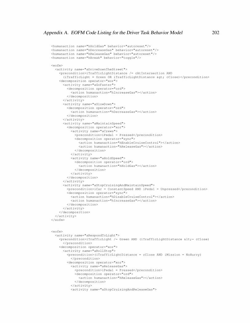
Appendix A. EOFM Code Listing for the Driver Task Behavior Model 202
<humanaction name="hHoldGas" behavior="autoreset"/><humanaction name="hDecreaseGas" behavior="autoreset"/><humanaction name="hReleaseGas" behavior="autoreset"/><humanaction name="hBreak" behavior="toggle"/>
<eofm><activity name="aDriveDownTheStreet">
<precondition>iTrafficLightDistance /= cAtIntersection AND(iTrafficLight = Green OR iTrafficLightDistance > cClose)</precondition>
<decomposition operator="xor"><activity name="aGoFaster"><decomposition operator="ord"><action humanaction="hIncreaseGas"></action>
</decomposition></activity><activity name="aSlowDown"><decomposition operator="ord"><action humanaction="hDecreaseGas"></action>
</decomposition></activity><activity name="aMaintainSpeed"><decomposition operator="xor"><activity name="aCrews"><precondition>iPedal = Pressed</precondition><decomposition operator="sync"><action humanaction="hEnableCruiseControl"></action><action humanaction="hReleaseGas"></action>
</decomposition></activity><activity name="aHoldSpeed"><decomposition operator="ord"><action humanaction="hHoldGas"></action>
</decomposition></activity>
</decomposition></activity><activity name="aStopCruisingAndMaintainSpeed"><precondition>iCar = ConstantSpeed AND iPedal = Unpressed</precondition><decomposition operator="sync"><action humanaction="hDisableCruiseControl"></action><action humanaction="hIncreaseGas"></action>
</decomposition></activity>
</decomposition></activity>
</eofm>
<eofm><activity name="aRespondToLight">
<precondition>iTrafficLight /= Green AND (iTrafficLightDistance <= cClose)</precondition>
<decomposition operator="xor"><activity name="aRollStop"><precondition>(iTrafficLightDistance = cClose AND iMission = NoHurry)</precondition>
<decomposition operator="xor"><activity name="aReleaseGas"><precondition>iPedal = Pressed</precondition><decomposition operator="ord"><action humanaction="hReleaseGas"></action>
</decomposition></activity><activity name="aStopCruisingAndReleaseGas">
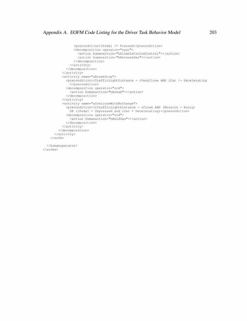
Appendix A. EOFM Code Listing for the Driver Task Behavior Model 203
<precondition>iPedal /= Pressed</precondition><decomposition operator="sync"><action humanaction="hDisableCruiseControl"></action><action humanaction="hReleaseGas"></action>
</decomposition></activity>
</decomposition></activity><activity name="aBreakStop"><precondition>iTrafficLightDistance = cVeryClose AND iCar /= Decelerating</precondition>
<decomposition operator="ord"><action humanaction="hBreak"></action>
</decomposition></activity><activity name="aContinueWithNoChange"><precondition>(iTrafficLightDistance = cClose AND iMission = Hurry)OR (iPedal = Unpressed and iCar = Decelerating)</precondition>
<decomposition operator="ord"><action humanaction="hHoldGas"></action>
</decomposition></activity>
</decomposition></activity>
</eofm>
</humanoperator></eofms>
Appendix B
EOFM to SAL Translator Validation
SAL was used to validate that translated instantiated EOFMs conformed to the formal
semantics. This was done by developing a number of temporal logic specification patterns
designed to verify that activities or actions within an EOFM instance conformed to the
transitions from Figure 2.3 and that the specified parallelism of activities and actions was
maintained for the different decomposition operators. These patterns were instantiated
for several examples designed to allow for the validation of the different execution state
conditions supported by the EOFM: activities decomposing into actions with the different
decomposition operators; activities decomposing into other activities with the different
decomposition operators; and multiple root activities in the same model. We first discuss
the specification pattern before discussing the applications for which they were applied.
B.1 Activity Execution State Transition Specification
Patterns
LTL specification patterns are described below for each of the of the transitions in Figure
2.3(a). In all, the activity variable represents the execution state variable for the activity
204
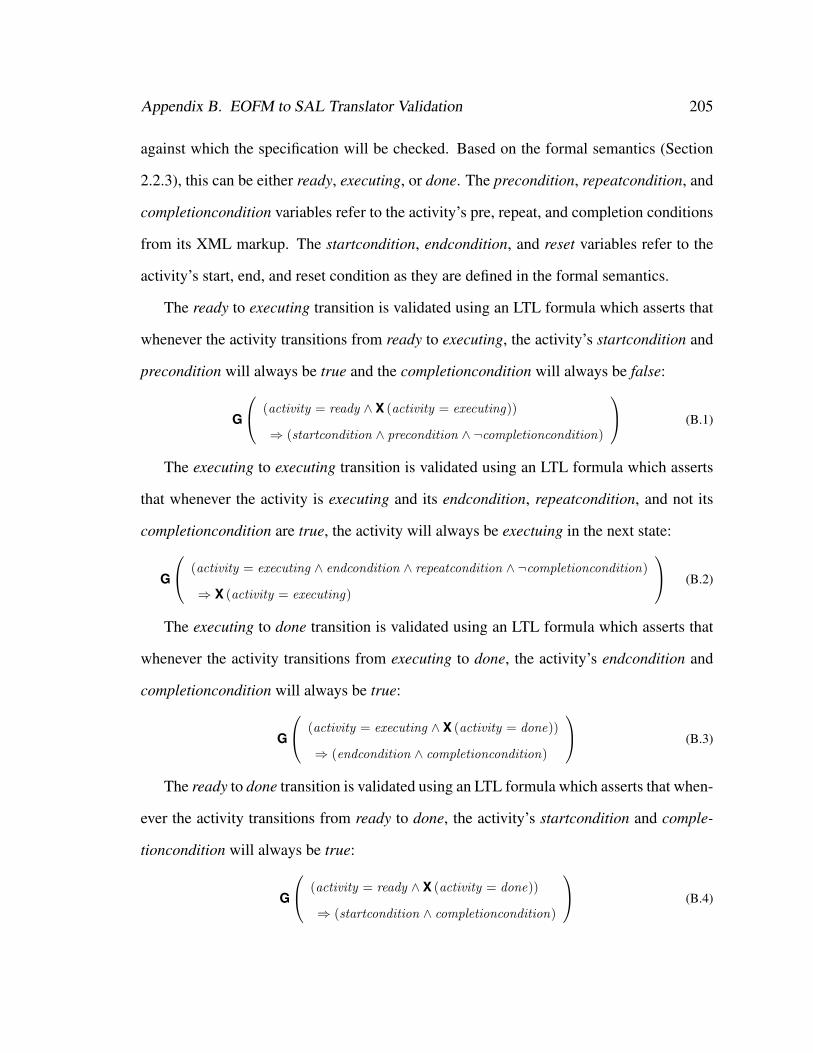
Appendix B. EOFM to SAL Translator Validation 205
against which the specification will be checked. Based on the formal semantics (Section
2.2.3), this can be either ready, executing, or done. The precondition, repeatcondition, and
completioncondition variables refer to the activity’s pre, repeat, and completion conditions
from its XML markup. The startcondition, endcondition, and reset variables refer to the
activity’s start, end, and reset condition as they are defined in the formal semantics.
The ready to executing transition is validated using an LTL formula which asserts that
whenever the activity transitions from ready to executing, the activity’s startcondition and
precondition will always be true and the completioncondition will always be false:
G
(activity = ready ∧ X (activity = executing))
⇒ (startcondition ∧ precondition ∧ ¬completioncondition)
(B.1)
The executing to executing transition is validated using an LTL formula which asserts
that whenever the activity is executing and its endcondition, repeatcondition, and not its
completioncondition are true, the activity will always be exectuing in the next state:
G
(activity = executing ∧ endcondition ∧ repeatcondition ∧ ¬completioncondition)
⇒ X (activity = executing)
(B.2)
The executing to done transition is validated using an LTL formula which asserts that
whenever the activity transitions from executing to done, the activity’s endcondition and
completioncondition will always be true:
G
(activity = executing ∧ X (activity = done))
⇒ (endcondition ∧ completioncondition)
(B.3)
The ready to done transition is validated using an LTL formula which asserts that when-
ever the activity transitions from ready to done, the activity’s startcondition and comple-
tioncondition will always be true:
G
(activity = ready ∧ X (activity = done))
⇒ (startcondition ∧ completioncondition)
(B.4)
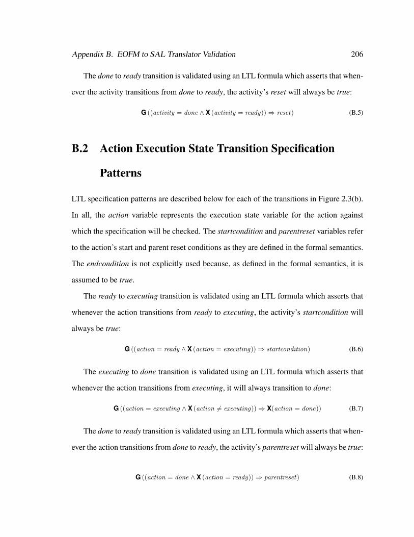
Appendix B. EOFM to SAL Translator Validation 206
The done to ready transition is validated using an LTL formula which asserts that when-
ever the activity transitions from done to ready, the activity’s reset will always be true:
G ((activity = done ∧ X (activity = ready))⇒ reset) (B.5)
B.2 Action Execution State Transition Specification
Patterns
LTL specification patterns are described below for each of the transitions in Figure 2.3(b).
In all, the action variable represents the execution state variable for the action against
which the specification will be checked. The startcondition and parentreset variables refer
to the action’s start and parent reset conditions as they are defined in the formal semantics.
The endcondition is not explicitly used because, as defined in the formal semantics, it is
assumed to be true.
The ready to executing transition is validated using an LTL formula which asserts that
whenever the action transitions from ready to executing, the activity’s startcondition will
always be true:
G ((action = ready ∧ X (action = executing))⇒ startcondition) (B.6)
The executing to done transition is validated using an LTL formula which asserts that
whenever the action transitions from executing, it will always transition to done:
G ((action = executing ∧ X (action 6= executing))⇒ X(action = done)) (B.7)
The done to ready transition is validated using an LTL formula which asserts that when-
ever the action transitions from done to ready, the activity’s parentreset will always be true:
G ((action = done ∧ X (action = ready))⇒ parentreset) (B.8)
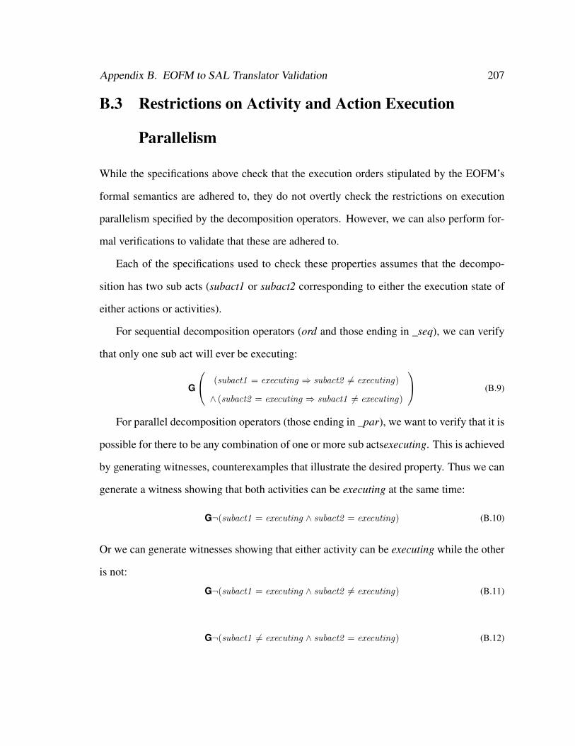
Appendix B. EOFM to SAL Translator Validation 207
B.3 Restrictions on Activity and Action Execution
Parallelism
While the specifications above check that the execution orders stipulated by the EOFM’s
formal semantics are adhered to, they do not overtly check the restrictions on execution
parallelism specified by the decomposition operators. However, we can also perform for-
mal verifications to validate that these are adhered to.
Each of the specifications used to check these properties assumes that the decompo-
sition has two sub acts (subact1 or subact2 corresponding to either the execution state of
either actions or activities).
For sequential decomposition operators (ord and those ending in _seq), we can verify
that only one sub act will ever be executing:
G
(subact1 = executing ⇒ subact2 6= executing)
∧ (subact2 = executing ⇒ subact1 6= executing)
(B.9)
For parallel decomposition operators (those ending in _par), we want to verify that it is
possible for there to be any combination of one or more sub actsexecuting. This is achieved
by generating witnesses, counterexamples that illustrate the desired property. Thus we can
generate a witness showing that both activities can be executing at the same time:
G¬(subact1 = executing ∧ subact2 = executing) (B.10)
Or we can generate witnesses showing that either activity can be executing while the other
is not:
G¬(subact1 = executing ∧ subact2 6= executing) (B.11)
G¬(subact1 6= executing ∧ subact2 = executing) (B.12)
Appendix B. EOFM to SAL Translator Validation 208
For the sync decomposition operator, we can verify that the each sub act is executing if
and only if the other is executing:
G(subact1 = executing ⇔ subact2 = executing) (B.13)
For the xor decomposition operator, we can verify that the each sub act is executing
only if the other is ready:
G
(subact1 = executing ⇒ subact2 = ready)
∧ (subact2 = executing ⇒ subact1 = ready)
(B.14)
B.4 Validation Applications
The validation applications were defined to cover a number of the structural conditions that
can arise in EOFM instances: activities decomposing into actions with the different decom-
position operators; activities decomposing into other activities; and multiple root activities
in the same model. In all cases the human task behavior model interacts with a simple
human-device interface model which can receive all human operator actions. The opera-
tor also receives Boolean inputs (precondition, repeatcondition, and completioncondition)
from the human-device interface model which give it access to simulated pre, repeat, and
completion conditions which can change between true and false (or remain unchanged) at
each step in a system model’s execution.
B.4.1 A Single Top Level Activity Decomposing Into Actions
The first set of validated applications used a human task behavior model of the form shown
in Figure D.1. Using this template, nine models were developed, one for each decom-
position operator, where a given decomposition operator would replace decomposition in
Figure D.1.
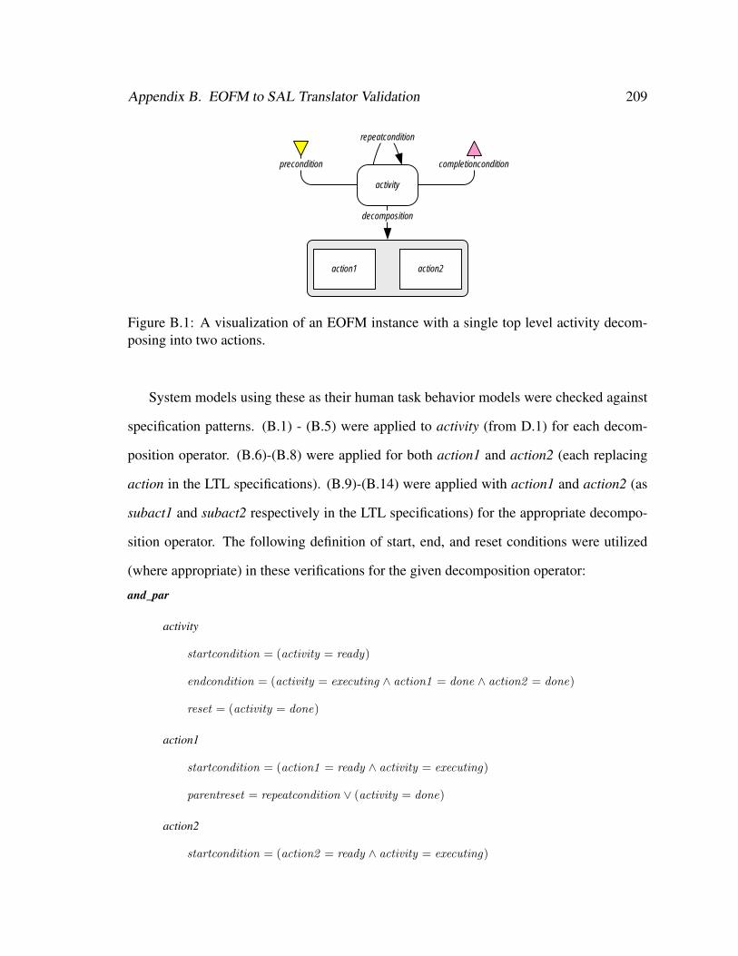
Appendix B. EOFM to SAL Translator Validation 209
activity
precondition
repeatcondition
completioncondition
decomposition
action1 action2
Figure B.1: A visualization of an EOFM instance with a single top level activity decom-posing into two actions.
System models using these as their human task behavior models were checked against
specification patterns. (B.1) - (B.5) were applied to activity (from D.1) for each decom-
position operator. (B.6)-(B.8) were applied for both action1 and action2 (each replacing
action in the LTL specifications). (B.9)-(B.14) were applied with action1 and action2 (as
subact1 and subact2 respectively in the LTL specifications) for the appropriate decompo-
sition operator. The following definition of start, end, and reset conditions were utilized
(where appropriate) in these verifications for the given decomposition operator:
and_par
activity
startcondition = (activity = ready)
endcondition = (activity = executing ∧ action1 = done ∧ action2 = done)
reset = (activity = done)
action1
startcondition = (action1 = ready ∧ activity = executing)
parentreset = repeatcondition ∨ (activity = done)
action2
startcondition = (action2 = ready ∧ activity = executing)
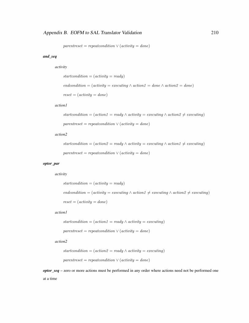
Appendix B. EOFM to SAL Translator Validation 210
parentreset = repeatcondition ∨ (activity = done)
and_seq
activity
startcondition = (activity = ready)
endcondition = (activity = executing ∧ action1 = done ∧ action2 = done)
reset = (activity = done)
action1
startcondition = (action1 = ready ∧ activity = executing ∧ action2 6= executing)
parentreset = repeatcondition ∨ (activity = done)
action2
startcondition = (action2 = ready ∧ activity = executing ∧ action1 6= executing)
parentreset = repeatcondition ∨ (activity = done)
optor_par
activity
startcondition = (activity = ready)
endcondition = (activity = executing ∧ action1 6= executing ∧ action2 6= executing)
reset = (activity = done)
action1
startcondition = (action1 = ready ∧ activity = executing)
parentreset = repeatcondition ∨ (activity = done)
action2
startcondition = (action2 = ready ∧ activity = executing)
parentreset = repeatcondition ∨ (activity = done)
optor_seq – zero or more actions must be performed in any order where actions need not be performed one
at a time
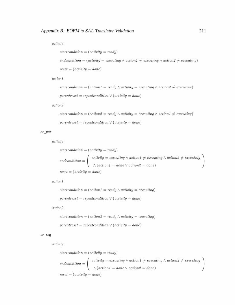
Appendix B. EOFM to SAL Translator Validation 211
activity
startcondition = (activity = ready)
endcondition = (activity = executing ∧ action1 6= executing ∧ action2 6= executing)
reset = (activity = done)
action1
startcondition = (action1 = ready ∧ activity = executing ∧ action2 6= executing)
parentreset = repeatcondition ∨ (activity = done)
action2
startcondition = (action2 = ready ∧ activity = executing ∧ action1 6= executing)
parentreset = repeatcondition ∨ (activity = done)
or_par
activity
startcondition = (activity = ready)
endcondition =
activity = executing ∧ action1 6= executing ∧ action2 6= executing
∧ (action1 = done ∨ action2 = done)
reset = (activity = done)
action1
startcondition = (action1 = ready ∧ activity = executing)
parentreset = repeatcondition ∨ (activity = done)
action2
startcondition = (action2 = ready ∧ activity = executing)
parentreset = repeatcondition ∨ (activity = done)
or_seq
activity
startcondition = (activity = ready)
endcondition =
activity = executing ∧ action1 6= executing ∧ action2 6= executing
∧ (action1 = done ∨ action2 = done)
reset = (activity = done)
Appendix B. EOFM to SAL Translator Validation 212
action1
startcondition = (action1 = ready ∧ activity = executing ∧ action2 6= executing)
parentreset = repeatcondition ∨ (activity = done)
action2
startcondition = (action2 = ready ∧ activity = executing ∧ action1 6= executing)
parentreset = repeatcondition ∨ (activity = done)
ord
activity
startcondition = (activity = ready)
endcondition = (activity = executing ∧ action2 = done)
reset = (activity = done)
action1
startcondition = (action1 = ready ∧ activity = executing)
parentreset = repeatcondition ∨ (activity = done)
action2
startcondition = (action2 = ready ∧ activity = executing ∧ action1 = done)
parentreset = repeatcondition ∨ (activity = done)
sync
activity
startcondition = (activity = ready)
endcondition = (activity = executing ∧ action1 = done ∧ action2 = done)
reset = (activity = done)
action1
startcondition = (action1 = ready ∧ action2 = ready ∧ activity = executing)
parentreset = repeatcondition ∨ (activity = done)
Appendix B. EOFM to SAL Translator Validation 213
action2
startcondition = (action2 = ready ∧ action1 = ready ∧ activity = executing)
parentreset = repeatcondition ∨ (activity = done)
xor
activity
startcondition = (activity = ready)
endcondition =
activity = executing ∧ action1 6= executing ∧ action2 6= executing
∧ (action1 = done ∨ action2 = done)
reset = (activity = done)
action1
startcondition = (action1 = ready ∧ action2 = ready ∧ activity = executing)
parentreset = repeatcondition ∨ (activity = done)
action2
startcondition = (action2 = ready ∧ action1 = ready ∧ activity = executing)
parentreset = repeatcondition ∨ (activity = done)
B.5 A Single Top Level Activity Decomposing Into
Activities
The second set of applications used in the validation test utilized a human task behavior
model of the form shown in Figure B.2. Using this template, eight models were developed,
one for each decomposition operator besides sync, where a given decomposition operator
would replace decomposition in Figure B.2.
System models using these as their human task behavior models were checked against
specification patterns. (B.1) - (B.5) were applied for both activity1 and activity2 (each
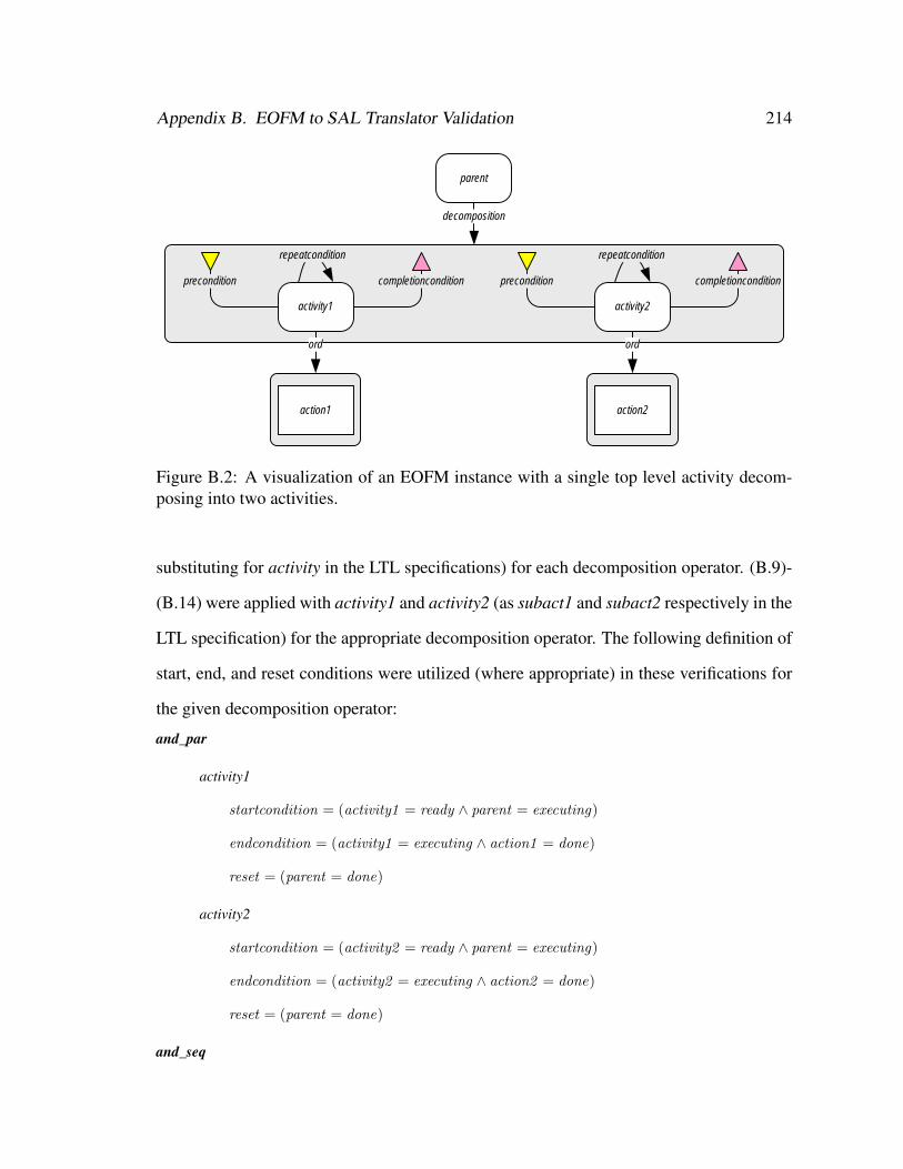
Appendix B. EOFM to SAL Translator Validation 214
parent
decomposition
activity1
precondition
repeatcondition
completioncondition
ord
action1
activity2
precondition
repeatcondition
completioncondition
ord
action2
Figure B.2: A visualization of an EOFM instance with a single top level activity decom-posing into two activities.
substituting for activity in the LTL specifications) for each decomposition operator. (B.9)-
(B.14) were applied with activity1 and activity2 (as subact1 and subact2 respectively in the
LTL specification) for the appropriate decomposition operator. The following definition of
start, end, and reset conditions were utilized (where appropriate) in these verifications for
the given decomposition operator:
and_par
activity1
startcondition = (activity1 = ready ∧ parent = executing)
endcondition = (activity1 = executing ∧ action1 = done)
reset = (parent = done)
activity2
startcondition = (activity2 = ready ∧ parent = executing)
endcondition = (activity2 = executing ∧ action2 = done)
reset = (parent = done)
and_seq
Appendix B. EOFM to SAL Translator Validation 215
activity1
startcondition = (activity1 = ready ∧ parent = executing ∧ activity2 6= executing)
endcondition = (activity1 = executing ∧ action1 = done)
reset = (parent = done)
activity2
startcondition = (activity2 = ready ∧ parent = executing ∧ activity1 6= executing)
endcondition = (activity2 = executing ∧ action2 = done)
reset = (parent = done)
optor_par
activity1
startcondition = (activity1 = ready ∧ parent = executing)
endcondition = (activity1 = executing ∧ action1 = done)
reset = (parent = done)
activity2
startcondition = (activity2 = ready ∧ parent = executing)
endcondition = (activity2 = executing ∧ action2 = done)
reset = (parent = done)
optor_seq
activity1
startcondition = (activity1 = ready ∧ parent = executing ∧ activity2 6= executing)
endcondition = (activity1 = executing ∧ action1 = done)
reset = (parent = done)
activity2
startcondition = (activity2 = ready ∧ parent = executing ∧ activity1 6= executing)
endcondition = (activity2 = executing ∧ action2 = done)
reset = (parent = done)
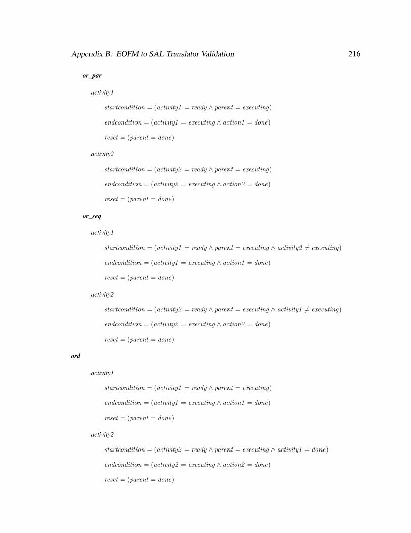
Appendix B. EOFM to SAL Translator Validation 216
or_par
activity1
startcondition = (activity1 = ready ∧ parent = executing)
endcondition = (activity1 = executing ∧ action1 = done)
reset = (parent = done)
activity2
startcondition = (activity2 = ready ∧ parent = executing)
endcondition = (activity2 = executing ∧ action2 = done)
reset = (parent = done)
or_seq
activity1
startcondition = (activity1 = ready ∧ parent = executing ∧ activity2 6= executing)
endcondition = (activity1 = executing ∧ action1 = done)
reset = (parent = done)
activity2
startcondition = (activity2 = ready ∧ parent = executing ∧ activity1 6= executing)
endcondition = (activity2 = executing ∧ action2 = done)
reset = (parent = done)
ord
activity1
startcondition = (activity1 = ready ∧ parent = executing)
endcondition = (activity1 = executing ∧ action1 = done)
reset = (parent = done)
activity2
startcondition = (activity2 = ready ∧ parent = executing ∧ activity1 = done)
endcondition = (activity2 = executing ∧ action2 = done)
reset = (parent = done)
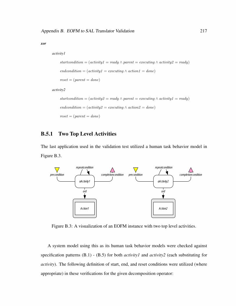
Appendix B. EOFM to SAL Translator Validation 217
xor
activity1
startcondition = (activity1 = ready ∧ parent = executing ∧ activity2 = ready)
endcondition = (activity1 = executing ∧ action1 = done)
reset = (parent = done)
activity2
startcondition = (activity2 = ready ∧ parent = executing ∧ activity1 = ready)
endcondition = (activity2 = executing ∧ action2 = done)
reset = (parent = done)
B.5.1 Two Top Level Activities
The last application used in the validation test utilized a human task behavior model in
Figure B.3.
aActivity1
precondition
repeatcondition
completioncondition
ord
Action1
aActivity2
precondition
repeatcondition
completioncondition
ord
Action2
Figure B.3: A visualization of an EOFM instance with two top level activities.
A system model using this as its human task behavior models were checked against
specification patterns (B.1) - (B.5) for both activity1 and activity2 (each substituting for
activity). The following definition of start, end, and reset conditions were utilized (where
appropriate) in these verifications for the given decomposition operator:

Appendix B. EOFM to SAL Translator Validation 218
activity1
startcondition = (activity1 = ready ∧ activity2 6= executing)
endcondition = (activity1 = executing ∧ action1 = done)
reset = (activity1 = done)
activity2
startcondition = (activity2 = ready ∧ activity1 6= executing)
endcondition = (activity2 = executing ∧ action2 = done)
reset = (activity2 = done)
B.6 Results
All specifications verified to true with the exception of those derived from (B.10)-(B.12)
which produced the expected witnesses.
B.7 Conclusions
While these applications do not exhaustively test every possible task behavior, they provide
reasonable confidence that the EOFM to SAL translation process is adhering to the formal
semantics, particularly for two activities and actions. They are correct for: an activity de-
composing into multiple actions with all possible decomposition operators; an activity de-
composing into multiple activities with all possible decomposition operators; and multiple
top level activities. Additionally, all activities utilized in the applications discussed in the
document were visually inspected to ensure that all observed counterexample conformed
to the formal semantics.

Appendix C
Phenotypical Erroneous Human
Behavior Validation
SAL was used to validate that translated instantiated EOFMs with phenotypical erroneous
behavior generation were exhibiting the expected behavior. This was done by constructing
a simple instantiated EOFM in which a single activity (aParent) with no conditions de-
composes into a single action (a) with an ordered (ord) decomposition operator. A formal
interface model was also created that could receive three different human actions (a, b, and
c all defined as humanaction nodes in the instantiated EOFM’s markup) and was capable
of recording up to four human actions in the sequence that they were submitted (action1,
action2, action3, and action4 which could assume values a, b, c, ε 1 depending on the
action that was performed).
Three formal models were built using these constructs where the interface model was
paired with translated versions of the instantiated EOFM2: one with no generated erroneous
behavior, one with a maximum of one erroneous act, and one with a maximum of two
erroneous acts.1No Action2The translated EOFMs were modified so that aParent would not transition from done to ready, allowing
the interface model to record the sequence actions performed for a single execution of aParent.
219
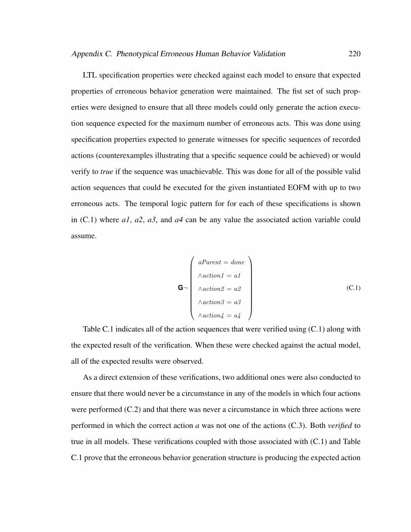
Appendix C. Phenotypical Erroneous Human Behavior Validation 220
LTL specification properties were checked against each model to ensure that expected
properties of erroneous behavior generation were maintained. The fist set of such prop-
erties were designed to ensure that all three models could only generate the action execu-
tion sequence expected for the maximum number of erroneous acts. This was done using
specification properties expected to generate witnesses for specific sequences of recorded
actions (counterexamples illustrating that a specific sequence could be achieved) or would
verify to true if the sequence was unachievable. This was done for all of the possible valid
action sequences that could be executed for the given instantiated EOFM with up to two
erroneous acts. The temporal logic pattern for for each of these specifications is shown
in (C.1) where a1, a2, a3, and a4 can be any value the associated action variable could
assume.
G¬
aParent = done
∧action1 = a1
∧action2 = a2
∧action3 = a3
∧action4 = a4
(C.1)
Table C.1 indicates all of the action sequences that were verified using (C.1) along with
the expected result of the verification. When these were checked against the actual model,
all of the expected results were observed.
As a direct extension of these verifications, two additional ones were also conducted to
ensure that there would never be a circumstance in any of the models in which four actions
were performed (C.2) and that there was never a circumstance in which three actions were
performed in which the correct action a was not one of the actions (C.3). Both verified to
true in all models. These verifications coupled with those associated with (C.1) and Table
C.1 prove that the erroneous behavior generation structure is producing the expected action

Appendix C. Phenotypical Erroneous Human Behavior Validation 221
Table C.1: Expected Verification Results for (C.1)
Expected Verification Result
Action Sequences Max. ] Erroneous Acts
a1 a2 a3 a4 0 1 2
ε ε ε ε × X Xa ε ε ε X X Xb ε ε ε × X Xc ε ε ε × X Xa a ε ε × X Xa b ε ε × X Xb a ε ε × X Xa c ε ε × X Xc a ε ε × X Xb b ε ε × × Xb c ε ε × × Xc b ε ε × × Xc c ε ε × × Xa a a ε × × Xa a b ε × × Xa b a ε × × Xb a a ε × × Xa a c ε × × Xa c a ε × × Xc a a ε × × Xa b c ε × × Xa c b ε × × Xb a c ε × × Xb c a ε × × Xc a b ε × × Xc b a ε × × X
Note. In the above a X indicates that when the associated action sequence is checked against the indicatedmodel with (C.1), that it was expected to return a counterexample. A × indicates that (C.1) was expected toverify to true, indicating the infeasibility of the action sequence.
sequences without producing any that weren’t for up to two erroneous behaviors.
G (a4 6= ε) (C.2)
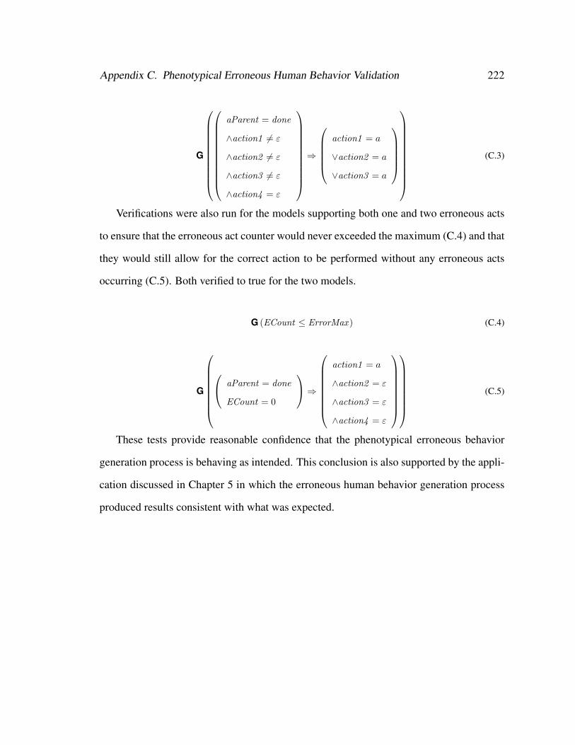
Appendix C. Phenotypical Erroneous Human Behavior Validation 222
G
aParent = done
∧action1 6= ε
∧action2 6= ε
∧action3 6= ε
∧action4 = ε
⇒
action1 = a
∨action2 = a
∨action3 = a
(C.3)
Verifications were also run for the models supporting both one and two erroneous acts
to ensure that the erroneous act counter would never exceeded the maximum (C.4) and that
they would still allow for the correct action to be performed without any erroneous acts
occurring (C.5). Both verified to true for the two models.
G (ECount ≤ ErrorMax ) (C.4)
G
aParent = done
ECount = 0
⇒
action1 = a
∧action2 = ε
∧action3 = ε
∧action4 = ε
(C.5)
These tests provide reasonable confidence that the phenotypical erroneous behavior
generation process is behaving as intended. This conclusion is also supported by the appli-
cation discussed in Chapter 5 in which the erroneous human behavior generation process
produced results consistent with what was expected.
Appendix D
Strategic Knowledge-based Erroneous
Behavior Validation
SAL was used to validate that translated instantiated EOFMs with strategic knowledge-
based erroneous behaviors were exhibiting the expected behavior. This was done by de-
veloping a number of temporal logic specification patterns designed to verify that models
were conforming to the activity execution state transitions from Figure 6.1, both normative
and erroneous. All validations were performed for the execution of activity (Figure D.1)
whose formal representation was created by translating its associated instantiated EOFM
into SAL with a maximum of one erroneous transition (KMax = 1). This translated EOFM
interacts with a simple human-device interface model which can receive all human opera-
tor actions. The operator also receives Boolean inputs (precondition, repeatcondition, and
completioncondition) from the human-device interface model which provide it with simu-
lated pre, repeat, and completion conditions which can change between true and false (or
remain unchanged) at each step in a system model’s execution.
activity has the following start and end conditions:
startcondition = (activity = ready)
223
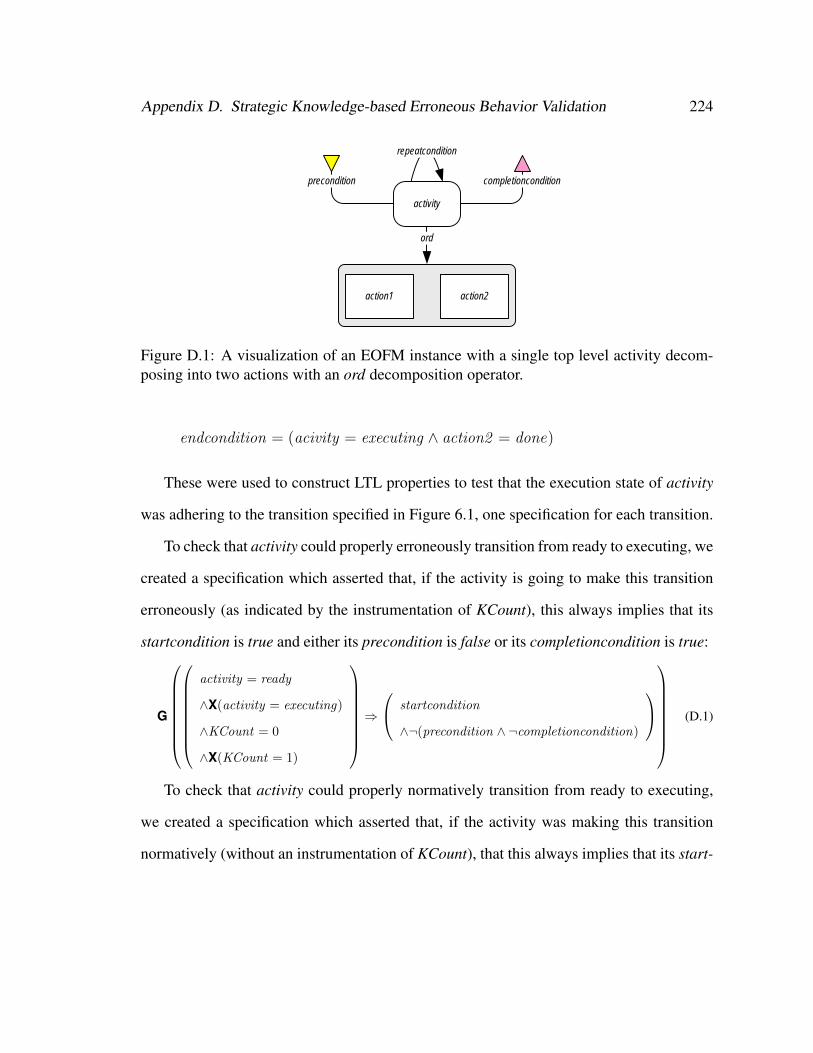
Appendix D. Strategic Knowledge-based Erroneous Behavior Validation 224
activity
precondition
repeatcondition
completioncondition
ord
action1 action2
Figure D.1: A visualization of an EOFM instance with a single top level activity decom-posing into two actions with an ord decomposition operator.
endcondition = (acivity = executing ∧ action2 = done)
These were used to construct LTL properties to test that the execution state of activity
was adhering to the transition specified in Figure 6.1, one specification for each transition.
To check that activity could properly erroneously transition from ready to executing, we
created a specification which asserted that, if the activity is going to make this transition
erroneously (as indicated by the instrumentation of KCount), this always implies that its
startcondition is true and either its precondition is false or its completioncondition is true:
G
activity = ready
∧X(activity = executing)
∧KCount = 0
∧X(KCount = 1)
⇒
startcondition
∧¬(precondition ∧ ¬completioncondition)
(D.1)
To check that activity could properly normatively transition from ready to executing,
we created a specification which asserted that, if the activity was making this transition
normatively (without an instrumentation of KCount), that this always implies that its start-
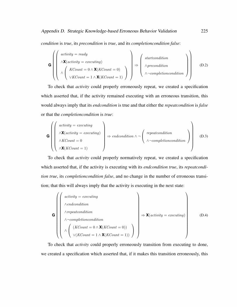
Appendix D. Strategic Knowledge-based Erroneous Behavior Validation 225
condition is true, its precondition is true, and its completioncondition false:
G
activity = ready
∧X(activity = executing)
∧
KCount = 0 ∧ X(KCount = 0)
∨KCount = 1 ∧ X(KCount = 1)
⇒
startcondition
∧precondition
∧¬completioncondition
(D.2)
To check that activity could properly erroneously repeat, we created a specification
which asserted that, if the activity remained executing with an erroneous transition, this
would always imply that its endcondition is true and that either the repeatcondition is false
or that the completioncondition is true:
G
activity = executing
∧X(activity = executing)
∧KCount = 0
∧X(KCount = 1)
⇒ endcondition ∧ ¬
repeatcondition
∧¬completioncondition
(D.3)
To check that activity could properly normatively repeat, we created a specification
which asserted that, if the activity is executing with its endcondition true, its repeatcondi-
tion true, its completioncondition false, and no change in the number of erroneous transi-
tion; that this will always imply that the activity is executing in the next state:
G
activity = executing
∧endcondition
∧repeatcondition
∧¬completioncondition
∧
(KCount = 0 ∧ X(KCount = 0))
∨(KCount = 1 ∧ X(KCount = 1))
⇒ X(activity = executing)
(D.4)
To check that activity could properly erroneously transition from executing to done,
we created a specification which asserted that, if it makes this transition erroneously, this
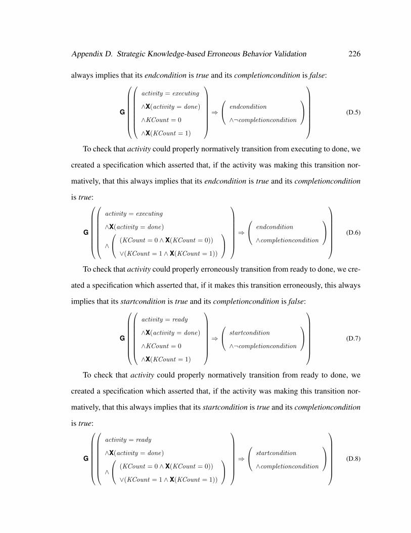
Appendix D. Strategic Knowledge-based Erroneous Behavior Validation 226
always implies that its endcondition is true and its completioncondition is false:
G
activity = executing
∧X(activity = done)
∧KCount = 0
∧X(KCount = 1)
⇒
endcondition
∧¬completioncondition
(D.5)
To check that activity could properly normatively transition from executing to done, we
created a specification which asserted that, if the activity was making this transition nor-
matively, that this always implies that its endcondition is true and its completioncondition
is true:
G
activity = executing
∧X(activity = done)
∧
(KCount = 0 ∧ X(KCount = 0))
∨(KCount = 1 ∧ X(KCount = 1))
⇒
endcondition
∧completioncondition
(D.6)
To check that activity could properly erroneously transition from ready to done, we cre-
ated a specification which asserted that, if it makes this transition erroneously, this always
implies that its startcondition is true and its completioncondition is false:
G
activity = ready
∧X(activity = done)
∧KCount = 0
∧X(KCount = 1)
⇒
startcondition
∧¬completioncondition
(D.7)
To check that activity could properly normatively transition from ready to done, we
created a specification which asserted that, if the activity was making this transition nor-
matively, that this always implies that its startcondition is true and its completioncondition
is true:
G
activity = ready
∧X(activity = done)
∧
(KCount = 0 ∧ X(KCount = 0))
∨(KCount = 1 ∧ X(KCount = 1))
⇒
startcondition
∧completioncondition
(D.8)
Appendix D. Strategic Knowledge-based Erroneous Behavior Validation 227
Finally, we checked that the number of erroneous transitions would never exceed the
maximum:
G (KCount ≥ 0 ∧KCount ≤ EMax ) (D.9)
All of these specifications verified to true or generated the expected witnesses giving
us reasonable confidence that the strategic knowledge-based erroneous human behavior
generation process was working as intended. This conclusion is also supported by the ap-
plication discussed in Chapter 6 in which the erroneous human behavior generation process
produced results consistent with what was expected.
Bibliography
[1] P. A. Abdulla, J. Deneux, G. Stålmarck, H. Ågren, and O. Åkerlund. Designing
safe, reliable systems using scade. In Proceedings of the First International Sympo-
sium on Leveraging Applications of Formal Methods, pages 115–129, Berlin, 2006.
Springer.
[2] G. D. Abowd, H. Wang, and A. F. Monk. A formal technique for automated dia-
logue development. In Proceedings of the 1st Conference on Designing Interactive
Systems, pages 219–226, New York, 1995. ACM.
[3] Y. Aït-Ameur and M. Baron. Formal and experimental validation approaches in HCI
systems design based on a shared event B model. International Journal on Software
Tools for Technology Transfer, 8(6):547–563, 2006.
[4] Y. Aït-Ameur, M. Baron, and P. Girard. Formal validation of HCI user tasks. In
Proceedings of the International Conference on Software Engineering Research and
Practice, pages 732–738, Las Vegas, 2003. CSREA Press.
[5] Y. Aït-Ameur, B. Breholee, P. Girard, L. Guittet, and F. Jambon. Formal verification
and validation of interactive systems specifications. In C. W. Johnson and P. A.
Palanque, editors, Proceedings of the 7th Working Conference on Human Error,
Safety and Systems Development, pages 61–76, Norwell, 2004. Kluwer Academics
Publishers.
228
BIBLIOGRAPHY 229
[6] H. Aljazzar and S. Leue. Debugging of dependability models using interactive vi-
sualization of counterexamples. In Proceedings of the 5th International Conference
on Quantitative Evaluation of Systems, pages 189–198, Los Alamitos, 2008. IEEE
Computer Society.
[7] R. Alur, T. A. Henzinger, F. Y. C. Mang, S. Qadeer, S. K. Rajamani, and S. Tasiran.
MOCHA: Modularity in model checking. In Proceedings of the 10th International
Conference on Computer Aided Verification, pages 521–525, Berlin, 1998. Springer.
[8] T. Amnell, G. Behrmann, J. Bengtsson, P. R. DArgenio, A. David, A. Fehnker,
T. Hune, B. Jeannet, K. G. Larsen, M. O. MÃuller, P. Pettersson, C. Weise, and
W. Yi. UPPAAL - now, next, and future. In Proceedings of the 4th Summer
School Modeling and Verification of Parallel Processes, pages 99–124, Berlin, 2001.
Springer.
[9] D. Arney, R. Jetley, P. Jones, I. Lee, and O. Sokolsky. Formal methods based de-
velopment of a PCA infusion pump reference model: Generic Infusion Pump (GIP)
project. In Proceedings of the 2007 Joint Workshop on High Confidence Medical
Devices, Software, and Systems and Medical Device Plug-and-Play Interoperability,
pages 23–33, Washington, DC, 2007. IEEE Computer Society.
[10] C. Artho, K. Havelund, and S. Honiden. Visualization of concurrent program ex-
ecutions. In Proceedings of the 31st Annual International Computer Software and
Applications Conference, pages 541–546, Piscataway, July 2007. IEEE.
[11] L. Bainbridge. Ironies of automation. Automatica, 19(6):775–780, 1983.
[12] BASI. Advanced technology aircraft safety survey report. Technical report, Depart-
ment of Transport and Regional Dedvelopment, Bureau of Air Safety Investigation,
BIBLIOGRAPHY 230
Civic Square, 1998. URL http://www.atsb.gov.au/media/704656/
advanced_technology_aircraft_safety_survey_report.pdf.
[13] S. Basnyat, N. Chozos, C. W. Johnson, and P. A. Palanque. Incident and accident
investigation techniques to inform model-based design of safety-critical interactive
systems. In Proceedings of the International Workshop on Design, Specification and
Verification of Interactive Systems, pages 51–66, Berlin, 2006. Springer.
[14] S. Basnyat, P. Palanque, B. Schupp, and P. Wright. Formal socio-technical barrier
modelling for safety-critical interactive systems design. Safety Science, 45(5):545–
565, 2007.
[15] S. Basnyat, P. A. Palanque, R. Bernhaupt, and E. Poupart. Formal modelling of in-
cidents and accidents as a means for enriching training material for satellite control
operations. In Proceedings of the Joint ESREL 2008 and 17th SRA-Europe Confer-
ence, pages CD–ROM, London, 2008. Taylor and Francis Group.
[16] E. J. Bass, S. T. Ernst-Fortin, R. L. Small, and J. Hogans. Architecture and de-
velopment environment of a knowledge-based monitor that facilitate incremental
knowledge-base development. IEEE Transactions on Systems, Man, and Cybernet-
ics, Part A: Systems and Humans, 34(4):441–449, 2004.
[17] R. Bastide and S. Basnyat. Error patterns: Systematic investigation of deviations
in task models. In Task Models and Diagrams for Users Interface Design, pages
109–121, Berlin, 2007. Springer.
[18] R. Bastide, D. Navarre, and P. Palanque. A tool-supported design framework for
safety critical interactive systems. Interacting with Computers, 15(3):309–328,
2003.
BIBLIOGRAPHY 231
[19] T. A. Basuki, A. Cerone, A. Griesmayer, and R. Schlatte. Model-checking user
behaviour using interacting components. Formal Aspects of Computing, pages 1–
18, 2009.
[20] Ipump Pain Management System Operator’s Manual. Baxter Heath Care Corpora-
tion, 1995.
[21] A. Blandford, R. Butterworth, and J. Good. Users as rational interacting agents:
Formalising assumptions about cognition and interaction. In Proceedings of the 4th
International Eurographics Workshop, on Design, Specification and Verification of
Interactive Systems, volume 97, pages 45–60, Berlin, 1997. Springer.
[22] A. Blandford, R. Butterworth, and P. Curzon. PUMA footprints: Linking theory and
craft skill in usability evaluation. In Proceedings of IFIP INTERACT’01: Human-
computer Interaction, pages 577–584, Amsterdam, 2001. IOS Press.
[23] A. Blandford, R. Butterworth, and P. Curzon. Models of interactive systems: A case
study on programmable user modelling. International Journal of Human-Computer
Studies, 60(2):149–200, 2004.
[24] W. Bogdanich. The radiation boom: Radiation offers new cures, and ways to do
harm, January 23 2010. URL http://www.nytimes.com/2010/01/24/
health/24radiation.html.
[25] M. L. Bolton and E. J. Bass. Formal modeling of erroneous human behavior and its
implications for model checking. In Proceedings of the Sixth NASA Langley Formal
Methods Workshop, pages 62–64, Hampton, 2008. NASA Langley Research Center.
[26] M. L. Bolton and E. J. Bass. A method for the formal verification of human inter-
active systems. In Proceedings of the 53rd Annual Meeting of the Human Factors
BIBLIOGRAPHY 232
and Ergonomics Society, pages 764–768, Santa Monica, 2009. Human Factors and
Ergonomics Society.
[27] M. L. Bolton and E. J. Bass. Building a formal model of a human-interactive sys-
tem: Insights into the integration of formal methods and human factors engineering.
In Proceedings of the 1st NASA Formal Methods Symposium, pages 6–15, Moffett
Field, 2009. NASA Ames Research Center.
[28] M. L. Bolton and E. J. Bass. Enhanced operator function model: A generic hu-
man task behavior modeling language. In Proceedings of the IEEE International
Conference on Systems Man and Cybernetics, pages 2983–2990, Piscataway, 2009.
IEEE.
[29] M. L. Bolton and E. J. Bass. Using task analytic models and phenotypes of erroneous
human behavior to discover system failures using model checking. In Proceedings
of the 54th Annual Meeting of the Human Factors and Ergonomics Society, Santa
Monica, 2010. Human Factors and Ergonomics Society. Accepted.
[30] M. L. Bolton and E. J. Bass. Using task analytic models to visualize model checker
counterexamples. In Proceedings of the International Conference on Systems Man
and Cybernetics, 2010. Under review.
[31] M. L. Bolton and E. J. Bass. Formally verifying human-automation interaction as
part of a system model: Limitations and tradeoffs. Innovations in Systems and
Software Engineering: A NASA Journal, In Press.
[32] M. L. Bolton, E. J. Bass, R. I. Siminiceanu, and M. Feary. Applications of formal
verification to human-automation interaction: Current practices and future develop-
ments. Human Factors, . Under review.
BIBLIOGRAPHY 233
[33] M. L. Bolton, R. I. Siminiceanu, and E. J. Bass. A systematic approach to model
checking human-automation interaction using task-analytic models. IEEE Transac-
tions on Systems, Man, and Cybernetics, Part A, . Under review.
[34] M. L. Bolton, E. J. Bass, and R. I. Siminiceanu. Using formal methods to predict hu-
man error and system failures. In Proceedings of the 2nd International Conference
on Applied Human Factors and Ergonomics, pages CD–ROM, Las Vegas, 2008.
Applied Human Factors and Ergonomics International.
[35] R. C. Boyatt and J. E. Sinclair. A “lightweight formal methods” perspective on
investigating aspects of interactive systems. In Pre-proceedings of the 2nd Interna-
tional Workshop on Formal Methods for Interactive Systems, pages 35–50, London,
2007. Queen Mary, University of London.
[36] J. Bredereke and A. Lankenau. A rigorous view of mode confusion. In Proceedings
of the 21st International Conference on Computer Safety, Reliability and Security,
pages 19–31, London, UK, 2002. Springer.
[37] J. Bredereke and A. Lankenau. Safety-relevant mode confusions–modelling and
reducing them. Reliability Engineering and System Safety, 88(3):229–245, 2005.
[38] P. Bumbulis, P. S. C. Alencar, D. D. Cowan, and C. J. P. Lucena. A framework for
machine-assisted user interface verification. In Proceedings of the 4th International
Conference on Algebraic Methodology and Software Technology, pages 461–474,
Berlin, 1995. Springer.
[39] J. R. Burch, E. M. Clarke, D. L. Dill, J. Hwang, and K. L. McMillan. Symbolic
model checking: 1020 states and beyond. Information and Computation, 98(2):142–
171, 1992.
BIBLIOGRAPHY 234
[40] J. B. Bushman, C. M. Mitchell, P. M. Jones, and K. S. Rubin. ALLY: An opera-
tor’s associate for cooperative supervisory control systems. IEEE Transactions on
Systems, Man and Cybernetics Part A: Systems and Humans, 23(1):111–128, 1993.
[41] B. Buth. Analyzing mode confusion: An approach using FDR2. In Proceeding
of the 23rd International Conference on Computer Safety, Reliability, and Security,
pages 101–114, Berlin, 2004. Springer.
[42] R. W. Butler, S. P. Miller, J. N. Potts, and V. A. Carreño. A formal methods approach
to the analysis of mode confusion. In Proceeding of the 17th Digital Avionics Sys-
tems Conference, pages C41/1–C41/8, Piscataway, 1998. IEEE.
[43] R. Butterworth, A. Blandford, and D. Duke. The role of formal proof in modelling
interactive behaviour. In Proceedings of the 5th International Eurographics Work-
shop on Design, Specification and Verification of Interactive Systems, pages 87–101,
Berlin, 1998. Springer.
[44] R. Butterworth, A. Blandford, and D. Duke. Demonstrating the cognitive plausi-
bility of interactive system specifications. Formal Aspects of Computing, 12(4):
237–259, 2000.
[45] M. D. Byrne and S. Bovair. A working memory model of a common procedural
error. Cognitive Science, 21(1):31–61, 1997.
[46] J. C. Campos and M. Harrison. Formally verifying interactive systems: A re-
view. In Proceedings of the Fouth International Eurographics Workshop on Design,
Specification, and Verification of Interactive Systems, pages 109–124, Berlin, 1997.
Springer.
BIBLIOGRAPHY 235
[47] J. C. Campos and M. Harrison. Model checking interactor specifications. Automated
Software Engineering, 8(3):275–310, 2001.
[48] J. C. Campos and M. D. Harrison. Systematic analysis of control panel interfaces us-
ing formal tools. In Proceedings of the 15th International Workshop on the Design,
Verification and Specification of Interactive Systems, pages 72–85, Berlin, 2008.
Springer.
[49] J. C. Campos and M. D. Harrison. Interaction engineering using the ivy tool. In Pro-
ceedings of the 1st ACM SIGCHI Symposium on Engineering Interactive Computing
Systems, pages 35–44, New York, 2009. ACM.
[50] S. M. Casey. Set phasers on stun: and other true tales of design, technology, and
human error. Aegean, Santa Barbara, 1993.
[51] A. Cerone, P. A. Lindsay, and S. Connelly. Formal analysis of human-computer
interaction using model-checking. In Proceedings of the 3rd IEEE International
Conference on Software Engineering and Formal Methods, pages 352–362, Los
Alamitos, 2005. IEEE Computer Society.
[52] M. Chechik and A. Gurfinkel. A framework for counterexample generation and
exploration. International Journal on Software Tools for Technology Transfer, 9(5):
429–445, 2007.
[53] R. W. Chu, C. M. Mitchell, and P. M. Jones. Using the operator function model and
OFMspert as the basis for an intelligent tutoring system: Towards a tutor/aid para-
digm for operators of supervisory control systems. IEEE Transactions on Systems,
Man and Cybernetics Part A: Systems and Humans, 25(7):1054–1075, 1995.
BIBLIOGRAPHY 236
[54] J. Clark and M. Murata. Relax NG specification. Committee Specification, 2001.
URL http://relaxng.org/spec-20011203.html.
[55] E. Clarke, O. Grumberg, S. Jha, Y. Lu, and H. Veith. Counterexample-guided ab-
straction refinement for symbolic model checking. Journal of the ACM, 50(5):752–
794, 2003.
[56] E. M. Clarke, O. Grumberg, and D. A. Peled. Model checking. MIT Press, Cam-
bridge, 1999.
[57] S. Combéfis and C. Pecheur. A bisimulation-based approach to the analysis of
human-computer interaction. In Proceedings of the ACM SIGCHI Symposium on
Engineering Interactive Computing Systems, New York, 2009. ACM.
[58] P. Cousot and R. Cousot. Abstract interpretation: A unified lattice model for static
analysis of programs by construction or approximation of fixpoints. In Proceed-
ings of the 4th ACM SIGACT-SIGPLAN Symposium on Principles of Programming
Languages, pages 238–252, New York, 1977. ACM.
[59] J. Coutaz, L. Nigay, D. Salber, A. Blandford, J. May, and R. Young. Four easy pieces
for assessing the usability of multimodal interaction: The CARE properties. In
Proceedings of the IFIP Interantional Conference on Human-Computer Interaction,
pages 115–120, Laxenburg, 1995. IFIP.
[60] J. Crow, D. Javaux, and J. Rushby. Models and mechanized methods that integrate
human factors into automation design. In Proceedings of the 2000 International
Conference on Human-computer Interaction in Aeronautics, pages 163–168, Menlo
Park, 2000. Advancement of Artificial Intelligence.
BIBLIOGRAPHY 237
[61] P. Curzon and A. Blandford. From a formal user model to design rules. In Proceed-
ings of the 9th International Workshop on Interactive Systems. Design, Specification,
and Verification, pages 1–15, London, 2002. Springer.
[62] P. Curzon and A. Blandford. Formally justifying user-centered design rules: A case
study on post-completion errors. In Proceedings of the 4th International Conference
on Integrated Formal Methods, pages 461–480, Berlin, 2004. Springer.
[63] P. Curzon, R. Rukšenas, and A. Blandford. An approach to formal verification of
humanUcomputer interaction. Formal Aspects of Computing, 19(4):513–550, 2007.
[64] M. Davis, G. Logemann, and D. Loveland. A machine program for theorem-
proving. Communications of the ACM, 5(7):394–397, 1962.
[65] L. De Moura, S. Owre, and N. Shankar. The SAL language manual. Technical
Report CSL-01-01, Computer Science Laboratory, SRI International, Menlo Park,
2003.
[66] L. de Moura, B. Dutertre, and N. Shankar. A tutorial on satisfiability modulo the-
ories. In Proceedings of the 19th International Conference on Computer Aided
Verification, pages 20–36, Berlin, 2007. Springer.
[67] A. Degani. Taming HAL: Designing interfaces beyond 2001. Macmillan, New York,
2004.
[68] A. Degani and M. Heymann. Formal verification of human-automation interaction.
Human Factors, 44(1):28–43, 2002.
[69] A. Degani and A. Kirlik. Modes in human-automation interaction: Initial observa-
tions about a modeling approach. In Proceedings of the IEEE International Confer-
BIBLIOGRAPHY 238
ence on Systems, Man and Cybernetics, volume 4, pages 3443–3450, Piscataway,
1995. IEEE.
[70] A. Degani, M. Heymann, and M. Shafto. Formal aspects of procedures: The prob-
lem of sequential correctness. In Proceedings of the 43rd Annual Meeting of the
Human Factors and Ergonomics Society, pages 1113–1117, Santa Monica, 1999.
Human Factors and Ergonomics Society.
[71] A. Degani, M. Shafto, and A. Kirlik. Modes in human-machine systems: Review,
classification, and application. International Journal of Aviation Psychology, 9(2):
125–138, 1999.
[72] Department of Defense. Reliability test methods, plans, and environments for
engineering development, qualification and production. Technical Report MIL-
HDBK-781, Department of Defense, Washington, DC, 1987. URL http://src.
alionscience.com/pdf/MIL-HDBK-781.pdf.
[73] D. L. Dill. The murphi verification system. In Proceedings of the 8th International
Conference on Computer Aided Verification, pages 390–393, New Brunswick, 1996.
Springer.
[74] A. Dix, M. Ghazali, S. Gill, J. Hare, and D. Ramduny-Ellis. Physigrams: Modelling
devices for natural interaction. Formal Aspects of Computing, pages 1–29, 2008.
[75] Y. Dong, C. R. Ramakrishnan, and S. A. Smolka. Evidence Explorer: A tool for
exploring model-checking proofs. In Proceedings of the 15th International Confer-
ence on Computer Aided Verification, pages 215–218, Berlin, 2003. Springer.
BIBLIOGRAPHY 239
[76] M. B. Dwyer, V. Carr, and L. Hines. Model checking graphical user interfaces
using abstractions. In Proceedings of the Sixth European Software Engineering
Conference, pages 244–261, New York, 1997. Springer.
[77] M. B. Dwyer, Robby, O. Tkachuk, and W. Visser. Analyzing interaction orderings
with model checking. In Proceedings of the 19th IEEE International Conference
on Automated Software Engineering, pages 154–163, Los Alamitos, 2004. IEEE
Computer Society.
[78] P. V. Eijk and M. Diaz, editors. Formal Description Technique LOTOS: Results of
the Esprit Sedos Project. Elsevier Science Inc., New York, 1989.
[79] E. A. Emerson. Temporal and modal logic. In J. van Leeuwen, A. R. Meyer, M. Ni-
vat, M. Paterson, and D. Perrin, editors, Handbook of Theoretical Computer Science,
chapter 16, pages 995–1072. MIT Press, Cambridge, 1990.
[80] FAA Human Factors Team. Federal aviation administration human factors
team report on: The interfaces between flightcrews and modern flight deck
systems. Technical report, Federal Aviation Administration, Washington, DC,
1996. URL http://www.faa.gov/training_testing/training/
aqp/library/media/interfac.pdf.
[81] M. Feary. Automatic detection of interaction vulnerabilities in an executable spec-
ification. In Proceedings of the 7th International Conference on Engineering Psy-
chology and Cognitive Ergonomics, pages 487–496, Berlin, 2007. Springer.
[82] R. E. Fields. Analysis of Erroneous Actions in the Design of Critical Systems. PhD
thesis, University of York, York, 2001.
BIBLIOGRAPHY 240
[83] Flight Safety Foundation. Accident description: Air canada flight 621,
1974. http://aviation-safety.net/database/record.php?id=
19700705-0.
[84] Flight Safety Foundation. Accident description: Loftleidir flight 509, 1974. http:
//aviation-safety.net/database/record.php?id=19730623-0.
[85] Formal Systems (Europe) Ltd. Failures-Divergence Refinement: FDR2 User Man-
ual. Formal Systems (Europe) Ltd, 6 edition, 2005. URL http://www.fsel.
com/fdr2_manual.html.
[86] K. Funk, C. Suroteguh, J. Wilson, and B. Lyall. Flight deck automation and task
management. In Proceedings of the IEEE International Conference on Systems Man
and Cybernetics, pages 863–868, Piscataway, 1998. IEEE.
[87] S. Göknur, M. L. Bolton, and E. J. Bass. Adding a motor control component to the
operator function model expert system to investigate air traffic management con-
cepts using simulation. In Proceedings of the IEEE International Conference and
Systems, Man, and Cybernetics, pages 886–892, Piscataway, 2004. IEEE.
[88] S. Graf and H. Saïdi. Verifying invariants using theorem proving. In Proceedings of
the 8th International Conference on Computer Aided Verification, pages 196–207,
London, 1996. Springer.
[89] E. L. Gunter, A. Yasmeen, C. A. Gunter, and A. Nguyen. Specifying and analyzing
workflows for automated identification and data capture. In Proceedings of the 42nd
Hawaii International Conference on System Sciences, pages 1–11, Los Alatimos,
2009. IEEE Computer Society.
BIBLIOGRAPHY 241
[90] N. Halbwachs, P. Caspi, P. Raymond, and D. Pilaud. The synchronous data flow pro-
gramming language LUSTRE. Proceedings of the IEEE, 79(9):1305–1320, 1991.
[91] D. Harel. Statecharts: A visual formalism for complex systems. Science of Com-
puter Programming, 8(3):231–274, 1987.
[92] D. Harel, H. Lachover, A. Naamad, A. Pnueli, M. Politi, R. Sherman, A. Shtull-
Trauring, and M. Trakhtenbrot. STATEMATE: A working environment for the
development of complex reactive systems. IEEE Transactions on Software Engi-
neering, 16(4):403–414, 1990.
[93] M. Harrison and D. Duke. A review of formalisms for describing interactive be-
haviour. In Proceedings of the Workshop on Software Engineering and Human-
Computer Interaction, pages 49–75, London, 1995. Springer.
[94] H. R. Hartson, A. C. Siochi, and D. Hix. The UAN: A user-oriented representa-
tion for direct manipulation interface designs. ACM Transactions on Information
Systems, 8(3):181–203, 1990.
[95] T. A. Henzinger. The theory of hybrid automata. In Proceedings of the 11th Annual
IEEE Symposium on Logic in Computer Science, pages 278–292, Washington, 1996.
IEEE Computer Society.
[96] T. A. Henzinger, Z. Manna, and A. Pnueli. Timed transition systems. In Proceedings
of the REX Workshop, pages 226–251, Berlin, 1991. Springer.
[97] M. Heymann and A. Degani. Formal analysis and automatic generation of user
interfaces: Approach, methodology, and an algorithm. Human Factors, 49(2):311–
330, 2007.
BIBLIOGRAPHY 242
[98] D. Hix and H. R. Hartson. Developing user interfaces: Ensuring usability through
product and process. John Wiley and Sons, Inc., New York, 1993.
[99] C. A. R. Hoare. Communicating sequential processes. Commun. ACM, 21(8):666–
677, 1978.
[100] E. Hollnagel. The phenotype of erroneous actions. International Journal of Man-
Machine Studies, 39(1):1–32, 1993.
[101] E. Hollnagel. Human reliability analysis: Context and control. Academic Press,
1993.
[102] E. Hollnagel, D. D. Woods, and N. Leveson. Resilience engineering: Concepts and
precepts. Ashgate Publishing Company, Surrey, 2006.
[103] G. Holzmann and D. Peled. An improvement in formal verification. In Proceedings
of the 7th International Conference on Formal Description Techniques, pages 197–
211, London, 1994. Chapman and Hall, Ltd.
[104] G. J. Holzmann. The Spin Model Checker, Primer and Reference Manual. Addison-
Wesley, Reading, 2003.
[105] D. Hughes and M. Dornheim. Accidents direct focus on cockpit automation. Avia-
tion Week and Space Technology, 142(5):52–54, 1995.
[106] A. Hussey, I. MacColl, and D. Carrington. Assessing usability from formal user-
interface designs. In Proceedings of the 2001 Austalian Software Engineering Con-
ference, pages 40–47, Los Alamitos, 2001. IEEE Computer Society.
[107] D. Jackson. Lightweight formal methods. In Proceedings of the International Sym-
posium of Formal Methods Europe: Formal Methods for Increasing Software Pro-
ductivity, Berlin, 2001. Springer.
BIBLIOGRAPHY 243
[108] D. Javaux. A method for predicting errors when interacting with finite state sys-
tems. How implicit learning shapes the user’s knowledge of a system. Reliability
Engineering and System Safety, 75:147–165, 2002.
[109] S. Jeon. Verification of function block diagram through verilog translation. Master’s
thesis, Korea Advanced Institute for Science and Technology, Daejeon, 2007.
[110] B. E. John and D. E. Kieras. Using GOMS for user interface design and evaluation:
Which technique? ACM Transactions Computer-Human Interaction, 3(4):287–319,
1996.
[111] B. E. John, K. Prevas, D. D. Salvucci, and K. Koedinger. Predictive human perfor-
mance modeling made easy. In Proceedings of the SIGCHI conference on Human
Factors in Computing Systems, pages 455–462, New York, 2004. ACM.
[112] C. W. Johnson. The formal analysis of human-computer interaction during accident
investigations. In Proceedings of the Cnference on People and Computers IX, pages
285–297, New York, 1994. Cambridge University Press.
[113] C. W. Johnson. The application of user modeling techniques to reason about the
human contribution to major accidents. In Proceedings of the 7th International
Conference on User Modeling, pages 13–22, Secaucus, 1999. Springer.
[114] C. W. Johnson and A. J. Telford. Extending the application of formal methods to
analyse human error and system failure during accident investigations. Software
Engineering Journal, 11(6):355–365, 1996.
[115] P. M. Jones. Human error and its amelioration. In Handbook of systems engineering
and management, pages 687–702. Wiley, Malden, 1997.
BIBLIOGRAPHY 244
[116] A. Joshi, S. P. Miller, and M. P. Heimdahl. Mode confusion analysis of a flight
guidance system using formal methods. In Proceedings of the 22nd Digital Avionics
Systems Conference, pages 2.D.1–1–2.D.1–12, Piscataway, October 2003. IEEE.
[117] N. Kamel and Y. Aït-Ameur. A formal model for care usability properties verifica-
tion in multimodal HCI. In Proceedings of the IEEE International Conference on
Pervasive Services, pages 341–348, Piscataway, 2007. IEEE.
[118] N. Kamel, Y. Aït-Ameur, S. A. Selouani, and H. Hamam. A formal model to han-
dle the adaptability of multimodal user interfaces. In Proceedings of the 1st Inter-
national Conference on Ambient Media and Systems, pages 1–7, Brussels, 2008.
Institute for Computer Sciences, Social-Informatics and Telecommunications Engi-
neering.
[119] P. Kemper and C. Tepper. Trace analysis–gain insight through modelchecking and
cycle reduction. Technical Report 06007, Dortmund University of Technology,
Dortmund, 2006.
[120] M. Kermelis. Towards an improved understanding of model-checking traces by
visualisation. Master’s thesis, University of York, York, 2003.
[121] D. E. Kieras and P. G. Polson. An approach to the formal analysis of user complex-
ity. International Journal of Man-Machine Studies, 22(4):365–394, 1985. Reprinted
as Kieras and Polson [122].
[122] D. E. Kieras and P. G. Polson. An approach to the formal analysis of user complex-
ity. International Journal of Human-Computers Studies, 51(2):405–434, 1999.
BIBLIOGRAPHY 245
[123] D. E. Kieras, S. D. Wood, and D. E. Meyer. Predictive engineering models based on
the EPIC architecture for a multimodal high-performance human-computer interac-
tion task. ACM Trans. Comput.-Hum. Interact., 4(3):230–275, 1997.
[124] B. Kirwan and L. K. Ainsworth. A Guide to Task Analysis. Taylor and Francis,
London, 1992.
[125] L. T. Kohn, J. Corrigan, and M. S. Donaldson. To Err is Human: Building a Safer
Health System. National Academy Press, Washington, 2000.
[126] P. Ladkin. AA965 Cali accident report: Near Buga, Colombia, Dec 20, 1995, 1996.
URL http://sunnyday.mit.edu/accidents/calirep.html.
[127] P. Le Hégaret. The w3c document object model (DOM), 2002. http://www.
w3.org/2002/07/26-dom-article.html.
[128] D. Leadbetter, A. Hussey, P. Lindsay, A. Neal, and M. Humphreys. Towards model
based prediction of human error rates in interactive systems. In Proceedings of the
Australasian User Interface Conference, pages 42–49, Los Alamitos, 2001. IEEE
Computer Society.
[129] A. Lecerof and F. Paternò. Automatic support for usability evaluation. IEEE Trans-
actions on Software Engineering, 24(10):863–888, 1998.
[130] N. G. Leveson and C. S. Turner. An investigation of the therac-25 accidents. Com-
puter, 26(7):18–41, 1993.
[131] N. G. Leveson, L. D. Pinnel, S. D. Sandys, S. K., and J. D. Reese. Analyzing soft-
ware specifications for mode confusion potential. In Proceedings of the Workshop
on Human Error and System Development, pages CD–ROM, Glasgow, 1997. Uni-
versity of Glasgow.

BIBLIOGRAPHY 246
[132] P. Lindsay and S. Connelly. Modelling erroneous operator behaviours for an air-
traffic control task. In Proceedings of the 3rd Australasian User Interface Confer-
ence, volume 7, pages 43–54, Melbourne, 2002. ACS.
[133] K. Loer and M. D. Harrison. An integrated framework for the analysis of dependable
interactive systems (IFADIS): Its tool support and evaluation. Automated Software
Engineering, 13(4):469–496, 2006.
[134] G. Lüttgen and V. Carreño. Analyzing mode confusion via model checking. In
Proceeding of Theoretical and Practical Aspects of SPIN Model Checking, pages
120–135, Berlin, 1999. Springer.
[135] M. J. Mahemoff and L. J. Johnston. Principles for a usability-oriented pattern lan-
guage. In Proceedings of the Australasian Conference on Computer-Human Inter-
action, pages 132–139, Los Alamitos, 1998. IEEE Computer Society.
[136] M. Mansouri-Samani, C. S. Pasareanu, J. J. Penix, P. C. Mehlitz, O. OŠMalley,
W. C. Visser, G. P. Brat, L. Z. Markosian, and T. T. Pressburger. Program model
checking: A practitionerŠs guide. Technical report, Intelligent Systems Division,
NASA Ames Research Center, Moffett Field, 2007.
[137] K. McMillan. The cadence smv model checker. http://www.kenmcmil.com/
smv.html.
[138] K. L. McMillan. Symbolic Model Checking: An Approach to the State Explosion
Problem. Carnegie Mellon University, Pittsburgh, 1993.
[139] C. M. Mitchell and R. A. Miller. A discrete control model of operator function:
A methodology for information dislay design. IEEE Transactions on Systems Man
Cybernetics Part A: Systems and Humans, 16(3):343–357, 1986.
BIBLIOGRAPHY 247
[140] K. L. Mosier and L. J. Skitka. Human decision makers and automated decision aids:
Made for each other? In R. Parasuraman and M. Mouloua, editors, Automation and
Human Performance: Theory and Applications, pages 201–220. Lawrence Erlbaum
Associates, Inc., Philadelphia, 1996.
[141] R. J. Mumaw, N. B. Sarter, and C. D. Wickens. Analysis of pilotsŠ monitoring and
performance on an automated flight deck. In Proceedings of the 11th International
Symposium on Aviation Psychology, pages CD–ROM, Dayton, 2001. Wright State
University.
[142] D. Norman. The psychology of everyday things. Basic Books, New York, 1988.
[143] D. A. Norman. The problem with automation: Inappropriate feedback and inter-
action, not over-automation. Philosophical Transactions of the Royal Society of
London. Series B, Biological Sciences, 327:585–593, 1990.
[144] NTSB. Grounding of the panamanian passenger ship royal majesty on rose and
crown shoal near nantucket, massachusetts june 10, 1995. Technical Report MAR-
97/01, National Transportation Safety Board, Washington, DC, 1997.
[145] NTSB. Runway overrun during landing, american airlines flight 1420, mcdon-
nell douglas md-82, n215aa, little rock, arkansas, june 1, 1999. Technical Report
NTSB/AAR-01/02, National Transportation Safety Board, Washington, DC, 2001.
[146] J. M. O’Hara, J. C. Higgins, W. S. Brown, R. Fink, J. Persensky, P. Lewis, J. Kramer,
A. Szabo, and M. A. Boggi. Human factors considerations with respect to emerging
technology in nuclear power plants. Technical Report NUREG/CR-6947, United
States Nuclear Regulatory Commission, Washington, DC, 2008.
BIBLIOGRAPHY 248
[147] M. Oishi, I. Mitchell, A. Bayen, C. Tomlin, and A. Degani. Hybrid verification of
an interface for an automatic landing. In Proceedings of the 41st IEEE Conference
on Decision and Control, pages 1607–1613, Piscataway, 2002. IEEE.
[148] M. Oishi, I. Hwang, and C. Tomlin. Immediate observability of discrete event sys-
tems with application to user-interface design. In Proceedings of the 42nd IEEE
Conference on Decision and Control, pages 2665–2672, Piscataway, 2003. IEEE.
[149] P. A. Palanque, R. Bastide, and V. Sengès. Validating interactive system design
through the verification of formal task and system models. In Proceedings of the
IFIP TC2/WG2.7 Working Conference on Engineering for Human-Computer Inter-
action, pages 189–212, London, 1996. Chapman and Hall, Ltd.
[150] P. A. Palanque, R. Bastide, and V. Senges. Validating interactive system design
through the verification of formal task and system models. In Proceedings of the
IFIP TC2/WG2.7 Working Conference on Engineering for Human-Computer Inter-
action, pages 189–212, London, 1996. Chapman and Hall, Ltd.
[151] E. Palmer. “Oops, it didn’t arm”- A case study of two automation surprises. In Pro-
ceedings of the 8th International Symposium on Aviation Psychology, pages 227–
232, Dayton, 1995. Wright State University.
[152] R. Parasuraman and V. Riley. Humans and automation: Use, misuse, disuse, abuse.
Human Factors, 39(2), 1997.
[153] D. L. Parnas. On the use of transition diagrams in the design of a user interface for an
interactive computer system. In Proceedings of the 24th National ACM Conference,
pages 379–385, New York, 1969. ACM.
BIBLIOGRAPHY 249
[154] F. Paternò. Formal reasoning about dialogue properties with automatic support.
Interacting with Computers, 9(2):173–196, 1997.
[155] F. Paternò and C. Santoro. Integrating model checking and HCI tools to help de-
signers verify user interface properties. In Proceedings of the 7th International
Workshop on Design, Specification, and Verification of Interactive Systems, pages
135–150, Berlin, 2001. Springer.
[156] F. Paternò, C. Mancini, and S. Meniconi. Concurtasktrees: A diagrammatic notation
for specifying task models. In Proceedings of the IFIP TC13 Interantional Confer-
ence on Human-Computer Interaction, pages 362–369, London, 1997. Chapman
and Hall, Ltd.
[157] F. Paternò, C. Santoro, and S. Tahmassebi. Formal model for cooperative tasks:
Concepts and an application for en-route air traffic control. In Proceedings of the 5th
International Conference on Design, Specification, and Verification of Interactive
Systems, pages 71–86, Vienna, 1998. Springer.
[158] C. Perrow. Normal accidents: Living with high-risk technologies. Princeton Uni-
versity Press, Princeton, 1999.
[159] J. Reason. Human Error. Cambridge University Press, New York, 1990.
[160] R. Rukšenas, P. Curzon, J. Back, and A. Blandford. Formal modelling of cognitive
interpretation. In Proceedings of the 13th International Workshop on Design, Spec-
ification, and Verification of Interactive Systems, pages 123–136, London, 2007.
Springer.
[161] R. Rukšenas, J. Back, P. Curzon, and A. Blandford. Formal modelling of salience
and cognitive load. In Proceedings of the 2nd International Workshop on Formal
BIBLIOGRAPHY 250
Methods for Interactive Systems, pages 57–75, Amsterdam, 2008. Elsevier Science
Publishers.
[162] R. Rukšenas, P. Curzon, A. Blandford, and J. Back. Combining human error verifi-
cation and timing analysis. In Proceedings of the 2007 Conferences on Engineering
Interactive Systems, pages 18–35, Berlin, 2009. Springer.
[163] J. Rushby. Using model checking to help discover mode confusions and other
automation surprises. Reliability Engineering and System Safety, 75(2):167–177,
2002.
[164] J. Rushby, J. Crow, and E. Palmer. An automated method to detect potential mode
confusions. In Proceedings of the 18th Digital Avionics Systems Conference, pages
4.B.2–1–4.B.2–6, Piscataway, 1999. IEEE.
[165] N. B. Sarter and D. D. Woods. How in the world did we ever get into that mode?
Mode error and awareness in supervisory control. Human Factors, 37(1):5–19,
1995.
[166] N. B. Sarter, R. J. Mumaw, and C. D. Wickens. Pilots’ monitoring strategies and
performance on automated flight decks: An empirical study combining behavioral
and eye-tracking data. Human Factors, 49(3):347–357, 2007.
[167] J. M. Schraagen, S. F. Chipman, and V. L. Shalin. Cognitive Task Analysis.
Lawrence Erlbaum Associates, Inc., Philadelphia, 2000.
[168] E. Sekigawa and M. Mecham. Pilots, A300 systems cited in Nagoya crash. Aviation
Week and Space Technology, 29:6–37, 1996.
BIBLIOGRAPHY 251
[169] N. Shankar. Symbolic analysis of transition systems. In Proceedings of the In-
ternational Workshop on Abstract State Machines, Theory and Applications, pages
287–302, London, 2000. Springer.
[170] T. B. Sheridan. Toward a general model of supervisory control. In T. B. Sheridan
and G. Johannsen, editors, Monitoring Behavior and Supervisory Control, pages
271–282. Taylor and Fancis, New York, 1976.
[171] T. B. Sheridan and R. Parasuraman. Human-automation interaction. Reviews of
human factors and ergonomics, 1(1):89–129, 2005.
[172] L. Sherry and M. Feary. Improving the aircraft cockpit user-interface: Using rule-
based expert system models. PC AI, 15(6):21–25, 2001.
[173] L. Sherry and J. Ward. A formalism for the specification of operationally embedded
reactive systems. In Proceeding of the 14th Digital Avionics Systems Conference,
pages 416–421, Piscataway, 1995. IEEE.
[174] L. Sherry, M. Feary, P. Polson, and E. Palmer. Formal method for identifying
two types of automation-surprises. Technical Report C69-5370-016, Honeywell,
Phoenix, 2000.
[175] R. Simmons and C. Pecheur. Automating model checking for autonomous systems.
In Proceedings of the AAAI Spring Symposium on Real-Time Autonomous Systems,
pages CD–ROM, Menlo Park. AAAI Press.
[176] P. J. Smith, C. E. McCoy, and C. Layton. Brittleness in the design of cooperative
problem-solving systems: the effects on user performance. IEEE Transactions on
Systems, Man and Cybernetics, Part A: Systems and Humans, 27(3):360–371, 1997.
BIBLIOGRAPHY 252
[177] P. C. Tae Jung Kim. smv2vcd, December 2001. http://www.cs.cmu.edu/
~modelcheck/smv2vcd.html.
[178] D. A. Thurman, A. R. Chappell, and C. M. Mitchell. An enhanced architecture for
OFMspert: A domain-independent system for intent inferencing. In Proceedings of
the IEEE International Conference on Systems, Man, and Cybernetics, Piscataway,
1998. IEEE.
[179] K. J. Vicente. Cognitive Work Analysis: Toward Safe, Oroductive, and Healthy
Computer-based Work. Lawrence Erlbaum Associates, Inc., Philadelphia, 1999.
[180] J. Voas. Fault injection for the masses. Computer, 30(12):129–130, 1997.
[181] P. H. Wheeler. Aspects of automation mode confusion. Master’s thesis, Mas-
sachusetts Institute of Technology, Cambridge, 2007.
[182] J. M. Wing. A specifier’s introduction to formal methods. Computer, 23(9):8, 10–
22, 24, 1990.
[183] D. D. Woods. Cognitive demands and activities in dynamic fault management: Ab-
ductive reasoning and disturbance management. In N. Stanton, editor, Human Fac-
tors in Alarm Design, pages 63–92. Taylor & Francis, Inc., Bristol, 1994.
[184] R. M. Young, T. R. G. Green, and T. Simon. Programmable user models for predic-
tive evaluation of interface designs. In Proceedings of the SIGCHI Conference on
Human Factors in Computing Systems, pages 15–19, New York, 1989. ACM.