Pololu USB AVR Programmer User's Guide - Pololu Robotics and
1
Using Pololu 3pi Robot Library with Flowcode
Document Revision: 1.02 Date: 15 November 2010
BiPOM Electronics 16301 Blue Ridge Road, Missouri City, Texas 77489 Telephone: 1-713-283-9970 Fax: 1-281-416-2806 E-mail: [email protected] Web: www.bipom.com
2
© 1996-2010 by BiPOM Electronics. All rights reserved. Using Pololu 3pi Robot Library with Flowcode. No part of this work may be reproduced in any manner without written permission of BiPOM Electronics. All trademarked names in this manual are the property of respective owners.
3
TABLE OF CONTENTS
1. Overview 4
2. Software setup 5
3. Create new project for Pololu 3pi robot 8
4
1. Overview Flowcode™ 4 is one of the world's most advanced graphical programming languages for microcontrollers. The great advantage of Flowcode™ is that it allows those with little to no programming experience to create complex electronic systems in minutes. Flowcode™ is available in more than twenty languages and currently supports the PICmicro, AVR and ARM series of microcontrollers. The Pololu 3pi robot is a complete, high-performance mobile platform featuring two micro metal gearmotors, five reflectance sensors, an 8×2 character LCD, a buzzer, and three user pushbuttons, all connected to a C-programmable ATmega328 microcontroller. Capable of speeds exceeding 3 feet per second, 3pi is a great first robot for ambitious beginners and a perfect second robot for those looking to move up from non-programmable or slower beginner robots. This document explains how to program Pololu 3pi robot with Flowcode programming language.
5
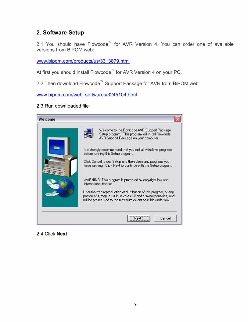
2. Software Setup 2.1 You should have Flowcode™ for AVR Version 4. You can order one of available versions from BiPOM web: www.bipom.com/products/us/3313879.html At first you should install Flowcode™ for AVR Version 4 on your PC. 2.2 Then download Flowcode™ Support Package for AVR from BiPOM web: www.bipom.com/web_softwares/3245104.html 2.3 Run downloaded file
2.4 Click Next
6
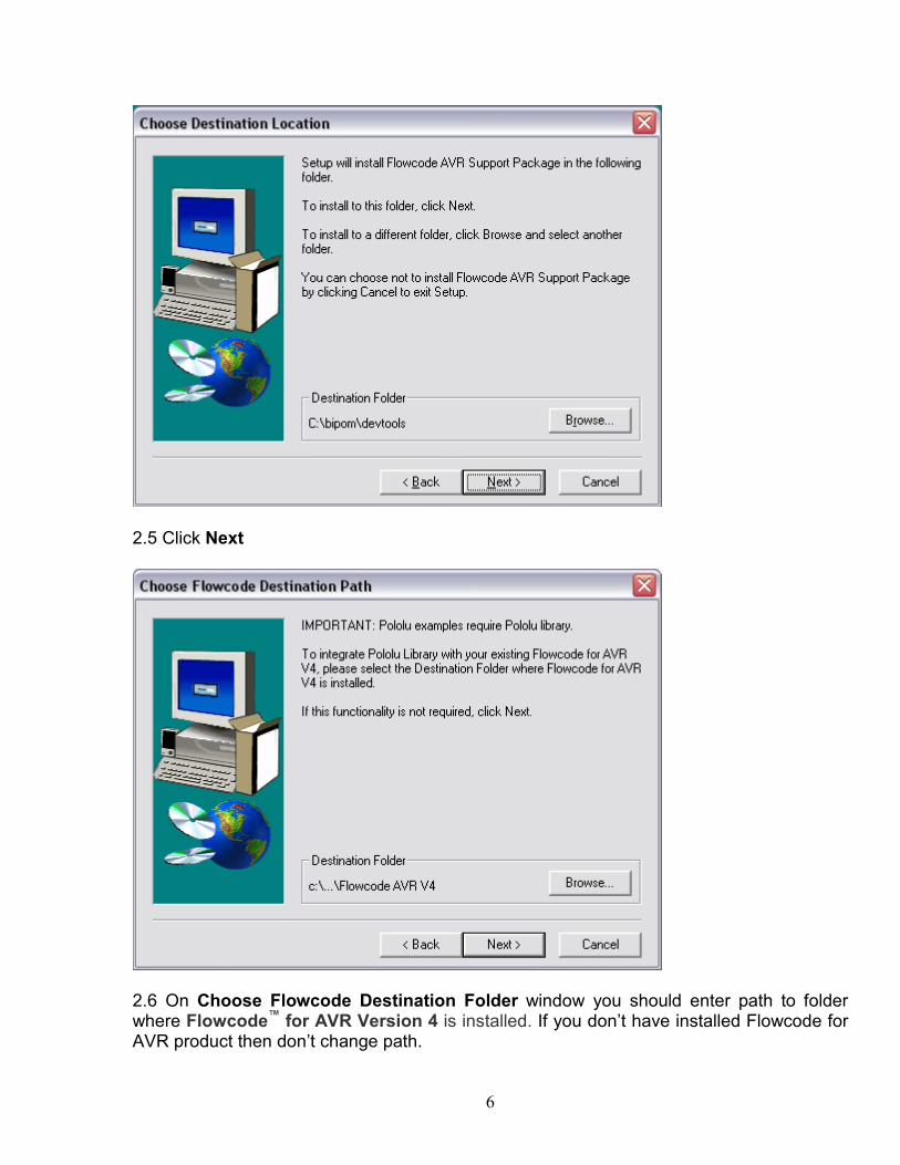
2.5 Click Next
2.6 On Choose Flowcode Destination Folder window you should enter path to folder where Flowcode™ for AVR Version 4 is installed. If you don’t have installed Flowcode for AVR product then don’t change path.
7
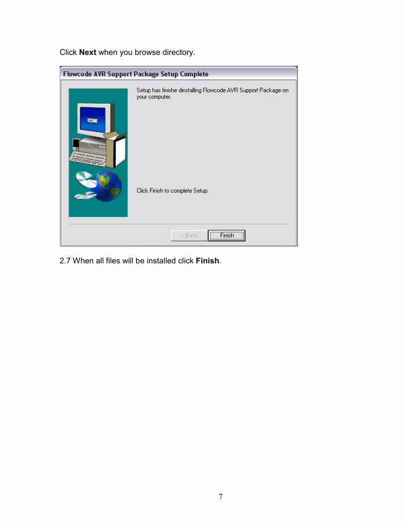
Click Next when you browse directory.
2.7 When all files will be installed click Finish.
8
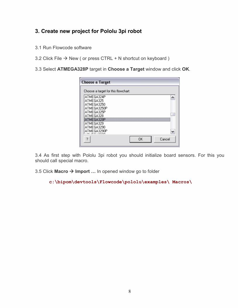
3. Create new project for Pololu 3pi robot 3.1 Run Flowcode software 3.2 Click File à New ( or press CTRL + N shortcut on keyboard ) 3.3 Select ATMEGA328P target in Choose a Target window and click OK.
3.4 As first step with Pololu 3pi robot you should initialize board sensors. For this you should call special macro. 3.5 Click Macro à Import … In opened window go to folder
c:\bipom\devtools\Flowcode\pololu\examples\ Macros\
9
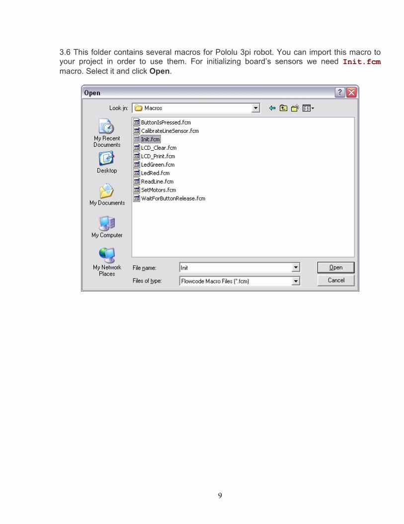
3.6 This folder contains several macros for Pololu 3pi robot. You can import this macro to your project in order to use them. For initializing board’s sensors we need Init.fcm macro. Select it and click Open.
10
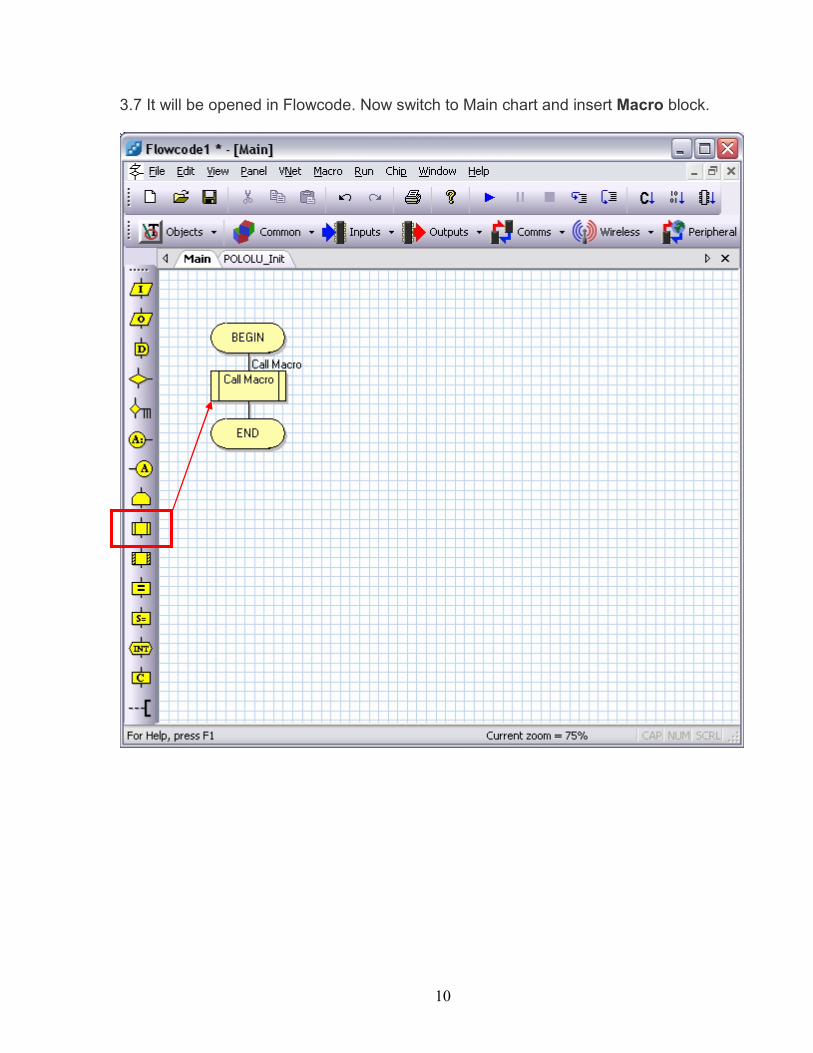
3.7 It will be opened in Flowcode. Now switch to Main chart and insert Macro block.
11
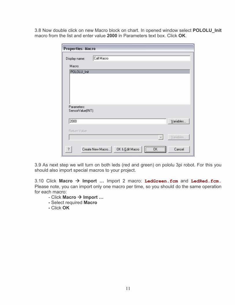
3.8 Now double click on new Macro block on chart. In opened window select POLOLU_Init macro from the list and enter value 2000 in Parameters text box. Click OK.
3.9 As next step we will turn on both leds (red and green) on pololu 3pi robot. For this you should also import special macros to your project. 3.10 Click Macro à Import … Import 2 macro: LedGreen.fcm and LedRed.fcm. Please note, you can import only one macro per time, so you should do the same operation for each macro: - Click Macro à Import … - Select required Macro - Click OK
12
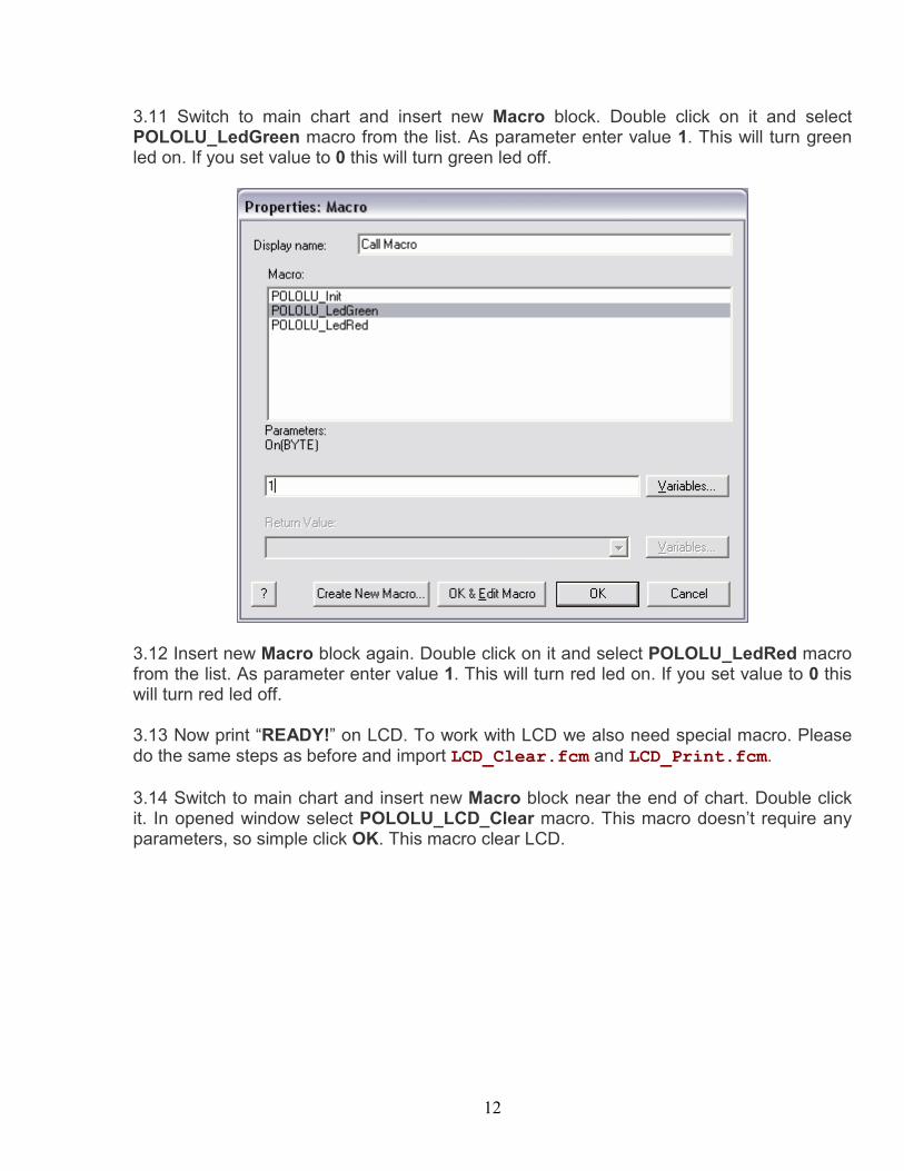
3.11 Switch to main chart and insert new Macro block. Double click on it and select POLOLU_LedGreen macro from the list. As parameter enter value 1. This will turn green led on. If you set value to 0 this will turn green led off.
3.12 Insert new Macro block again. Double click on it and select POLOLU_LedRed macro from the list. As parameter enter value 1. This will turn red led on. If you set value to 0 this will turn red led off. 3.13 Now print “READY!” on LCD. To work with LCD we also need special macro. Please do the same steps as before and import LCD_Clear.fcm and LCD_Print.fcm. 3.14 Switch to main chart and insert new Macro block near the end of chart. Double click it. In opened window select POLOLU_LCD_Clear macro. This macro doesn’t require any parameters, so simple click OK. This macro clear LCD.
13
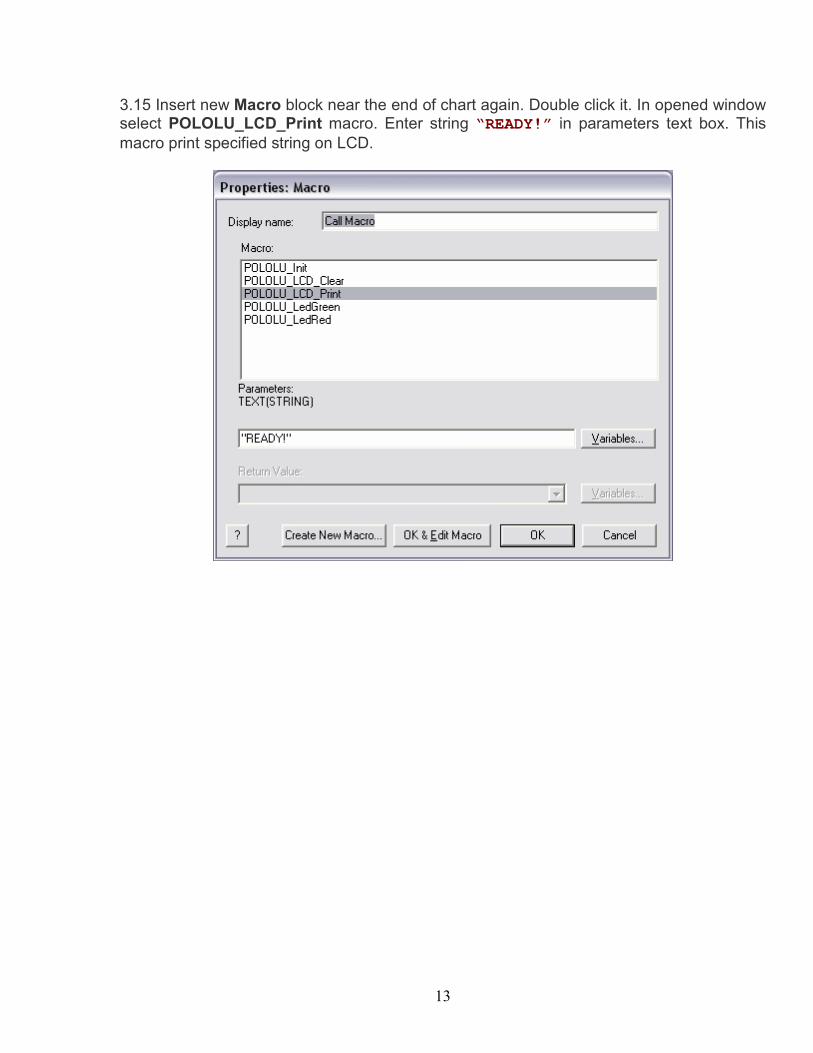
3.15 Insert new Macro block near the end of chart again. Double click it. In opened window select POLOLU_LCD_Print macro. Enter string “READY!” in parameters text box. This macro print specified string on LCD.
14
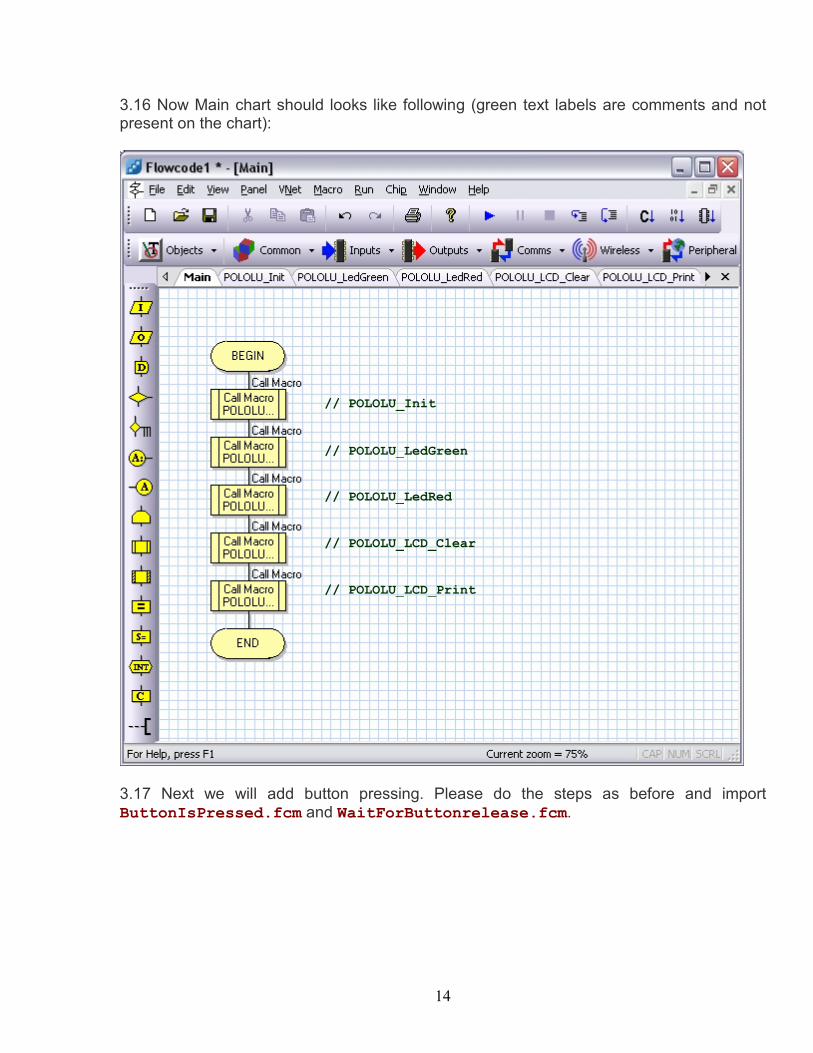
3.16 Now Main chart should looks like following (green text labels are comments and not present on the chart):
3.17 Next we will add button pressing. Please do the steps as before and import ButtonIsPressed.fcm and WaitForButtonrelease.fcm.
// POLOLU_Init
// POLOLU_LedGreen
// POLOLU_LedRed
// POLOLU_LCD_Clear
// POLOLU_LCD_Print
15
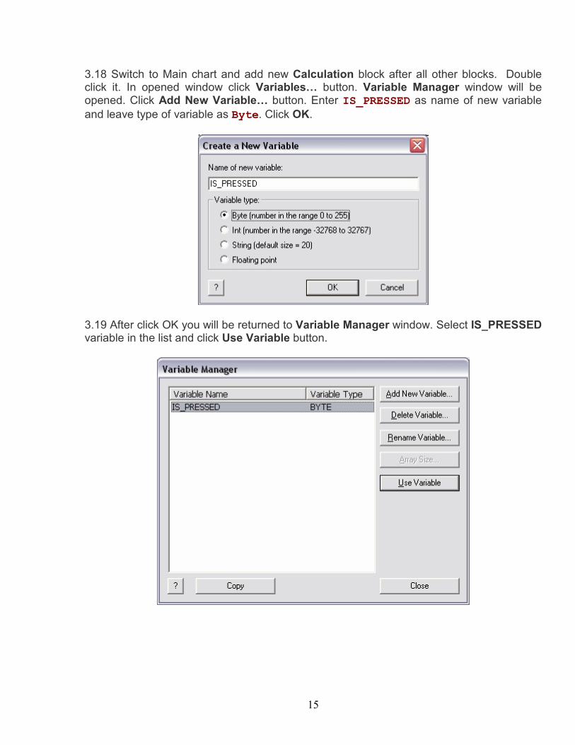
3.18 Switch to Main chart and add new Calculation block after all other blocks. Double click it. In opened window click Variables… button. Variable Manager window will be opened. Click Add New Variable… button. Enter IS_PRESSED as name of new variable and leave type of variable as Byte. Click OK.
3.19 After click OK you will be returned to Variable Manager window. Select IS_PRESSED variable in the list and click Use Variable button.
16
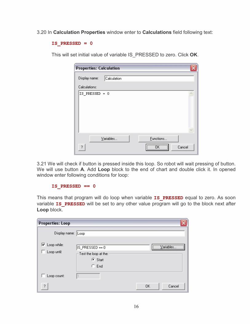
3.20 In Calculation Properties window enter to Calculations field following text:
IS_PRESSED = 0
This will set initial value of variable IS_PRESSED to zero. Click OK.
3.21 We will check if button is pressed inside this loop. So robot will wait pressing of button. We will use button A. Add Loop block to the end of chart and double click it. In opened window enter following conditions for loop:
IS_PRESSED == 0 This means that program will do loop when variable IS_PRESSED equal to zero. As soon variable IS_PRESSED will be set to any other value program will go to the block next after Loop block.
17
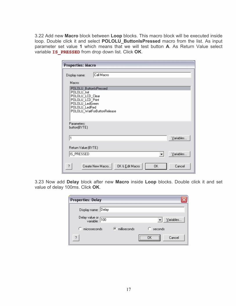
3.22 Add new Macro block between Loop blocks. This macro block will be executed inside loop. Double click it and select POLOLU_ButtonIsPressed macro from the list. As input parameter set value 1 which means that we will test button A. As Return Value select variable IS_PRESSED from drop down list. Click OK.
3.23 Now add Delay block after new Macro inside Loop blocks. Double click it and set value of delay 100ms. Click OK.
18
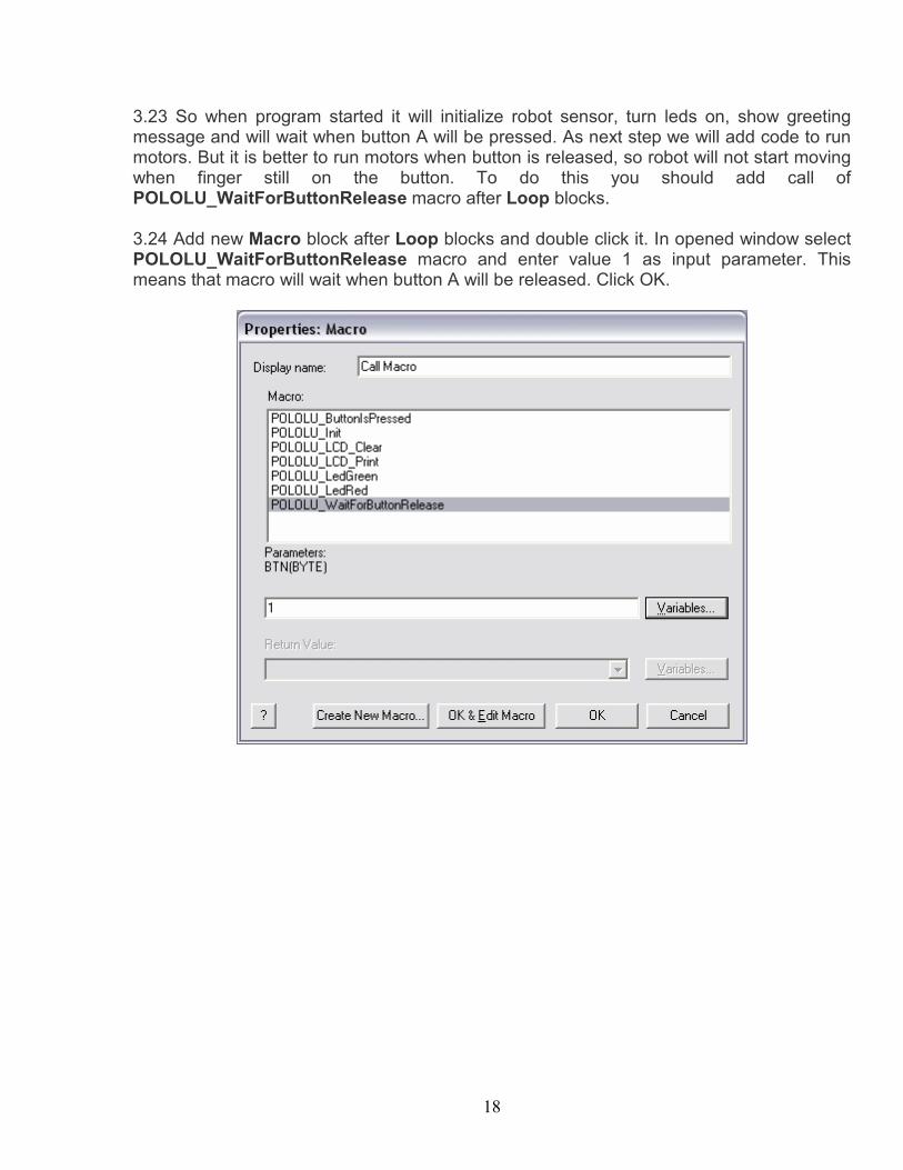
3.23 So when program started it will initialize robot sensor, turn leds on, show greeting message and will wait when button A will be pressed. As next step we will add code to run motors. But it is better to run motors when button is released, so robot will not start moving when finger still on the button. To do this you should add call of POLOLU_WaitForButtonRelease macro after Loop blocks. 3.24 Add new Macro block after Loop blocks and double click it. In opened window select POLOLU_WaitForButtonRelease macro and enter value 1 as input parameter. This means that macro will wait when button A will be released. Click OK.
19
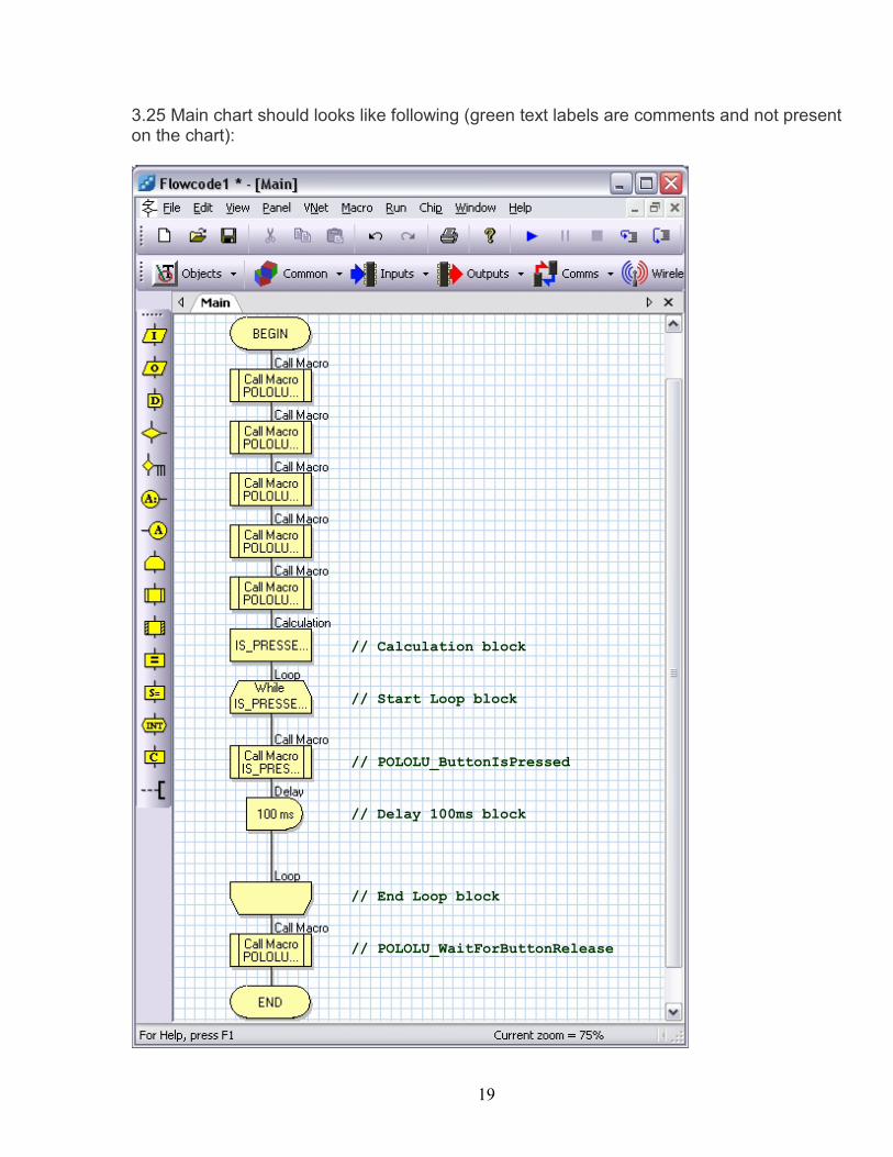
3.25 Main chart should looks like following (green text labels are comments and not present on the chart):
// Calculation block
// Start Loop block
// POLOLU_ButtonIsPressed
// Delay 100ms block
// End Loop block
// POLOLU_WaitForButtonRelease
20
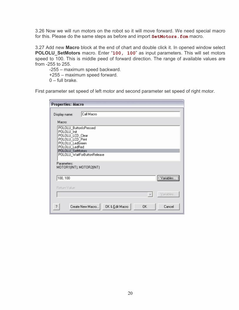
3.26 Now we will run motors on the robot so it will move forward. We need special macro for this. Please do the same steps as before and import SetMotors.fcm macro. 3.27 Add new Macro block at the end of chart and double click it. In opened window select POLOLU_SetMotors macro. Enter “100, 100” as input parameters. This will set motors speed to 100. This is middle peed of forward direction. The range of available values are from -255 to 255.
-255 – maximum speed backward. +255 – maximum speed forward. 0 – full brake.
First parameter set speed of left motor and second parameter set speed of right motor.
21
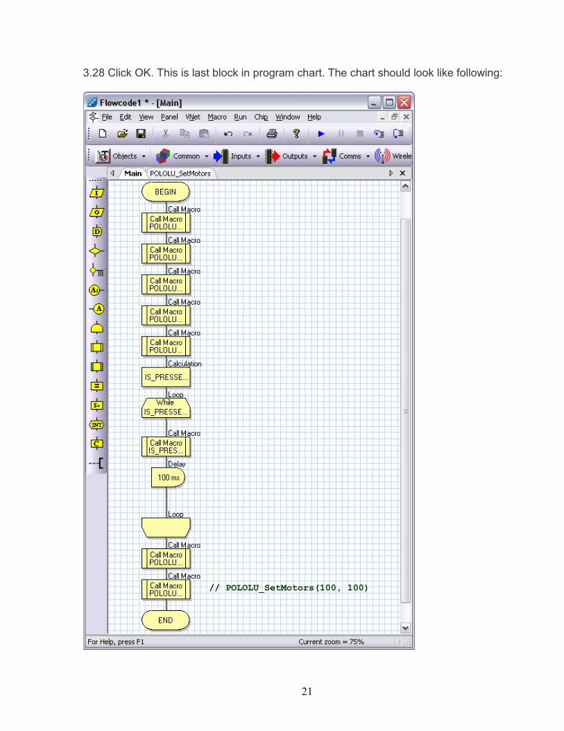
3.28 Click OK. This is last block in program chart. The chart should look like following:
// POLOLU_SetMotors(100, 100)
22
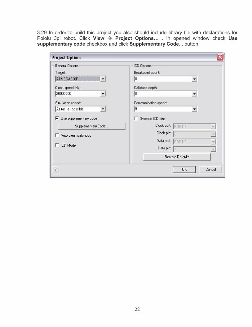
3.29 In order to build this project you also should include library file with declarations for Pololu 3pi robot. Click View à Project Options… . In opened window check Use supplementary code checkbox and click Supplementary Code... button.
23
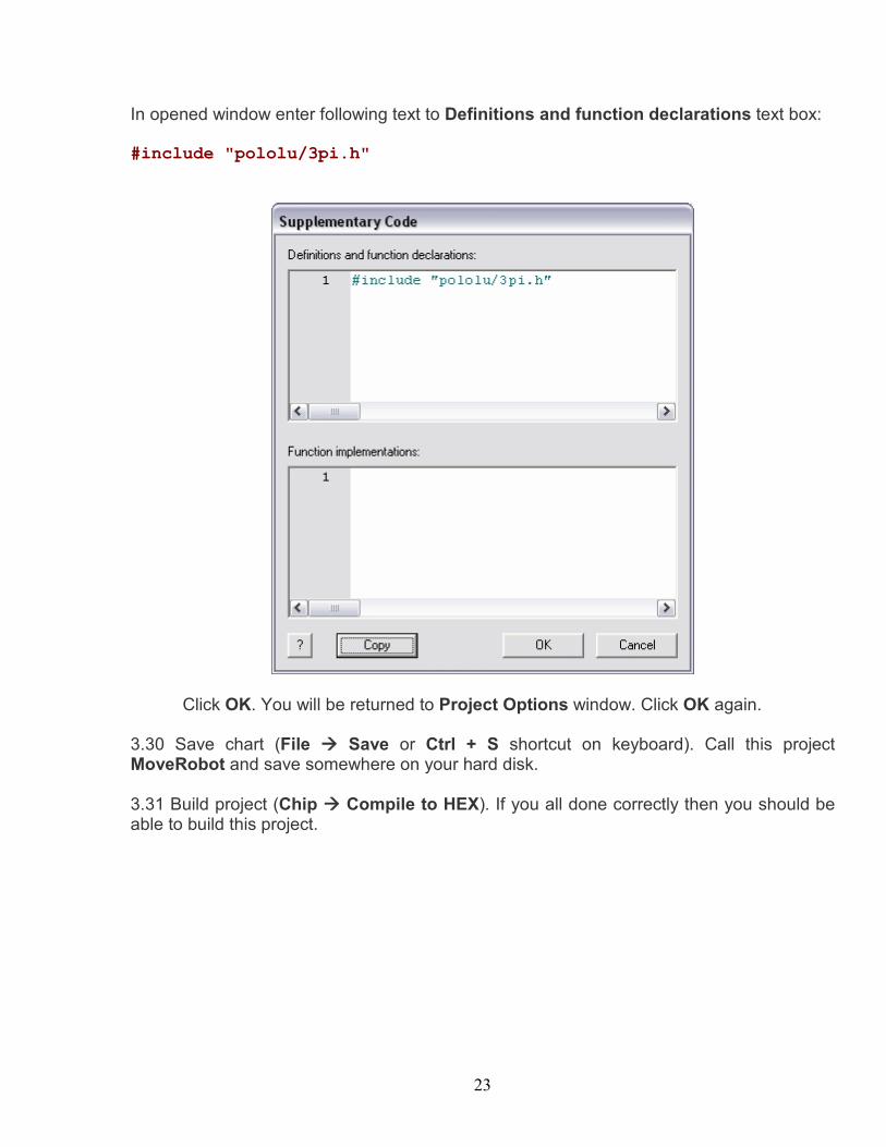
In opened window enter following text to Definitions and function declarations text box: #include "pololu/3pi.h"
Click OK. You will be returned to Project Options window. Click OK again. 3.30 Save chart (File à Save or Ctrl + S shortcut on keyboard). Call this project MoveRobot and save somewhere on your hard disk. 3.31 Build project (Chip à Compile to HEX). If you all done correctly then you should be able to build this project.