
Using on- machine probing to drive process capability · machine probing to drive process...
36
apply innovation TM © Renishaw 2007 In-process measurement on a machine tool – fact or fiction? Using on- machine probing to drive process capability Marc Saunders General Manager UK Sales Using on- machine probing to drive process capability Marc Saunders General Manager UK Sales
Transcript of Using on- machine probing to drive process capability · machine probing to drive process...

apply innovationTM
© Renishaw 2007
In-process measurement on a machine tool – fact or fiction?
Using on-machine probing to drive process capability
Marc SaundersGeneral ManagerUK Sales
Using on-machine probing to drive process capability
Marc SaundersGeneral ManagerUK Sales

apply innovationTM
Slide 28/1/2007
© Renishaw 2007
FACT!
• At Renishaw’s factory at Stonehouse, in-process measurement is indispensable
– 70 CNC machines
– 300,000+ parts per month
– 78 direct staff (over 3 shifts)
– Machines run unattended for up to 36 hours
– 2000 automated batch changeovers
apply innovationTM
Slide 38/1/2007
© Renishaw 2007
Agenda
• Goals of in-process inspection
• Productive Process PyramidTM
• Machine performance optimisation
• Calibration of 5-axis machine behaviour
• Impact of in-cycle process control
• The importance of temperature
• On-machine verification
apply innovationTM
Slide 48/1/2007
© Renishaw 2007
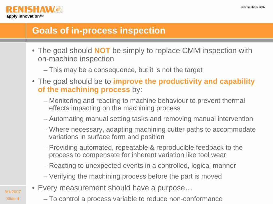
Goals of in-process inspection
• The goal should NOT be simply to replace CMM inspection with on-machine inspection
– This may be a consequence, but it is not the target
• The goal should be to improve the productivity and capability of the machining process by:
– Monitoring and reacting to machine behaviour to prevent thermal effects impacting on the machining process
– Automating manual setting tasks and removing manual intervention– Where necessary, adapting machining cutter paths to accommodate
variations in surface form and position– Providing automated, repeatable & reproducible feedback to the
process to compensate for inherent variation like tool wear– Reacting to unexpected events in a controlled, logical manner– Verifying the machining process before the part is moved
• Every measurement should have a purpose…– To control a process variable to reduce non-conformance

apply innovationTM
Slide 58/1/2007
© Renishaw 2007
Agenda
• Goals of in-process inspection
• Productive Process PyramidTM
• Machine performance optimisation
• Calibration of 5-axis machine behaviour
• Impact of in-cycle process control
• The importance of temperature
• On-machine verification
apply innovationTM
Slide 68/1/2007
© Renishaw 2007
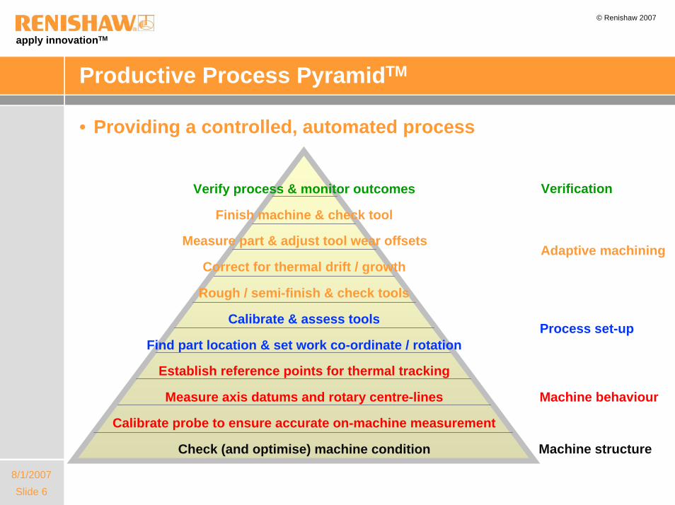
Productive Process PyramidTM
VerificationVerify process & monitor outcomes
Machine structureCheck (and optimise) machine condition
Machine behaviour
Calibrate probe to ensure accurate on-machine measurement
Measure axis datums and rotary centre-lines
Establish reference points for thermal tracking
Process set-upFind part location & set work co-ordinate / rotation
Calibrate & assess tools
Adaptive machining
Finish machine & check tool
Measure part & adjust tool wear offsets
Correct for thermal drift / growth
Rough / semi-finish & check tools
• Providing a controlled, automated process
apply innovationTM
Slide 78/1/2007
© Renishaw 2007
Agenda
• Goals of in-process inspection
• Productive Process PyramidTM
• Machine performance optimisation
• Calibration of 5-axis machine behaviour
• Impact of in-cycle process control
• The importance of temperature
• On-machine verification
apply innovationTM
Slide 88/1/2007
© Renishaw 2007
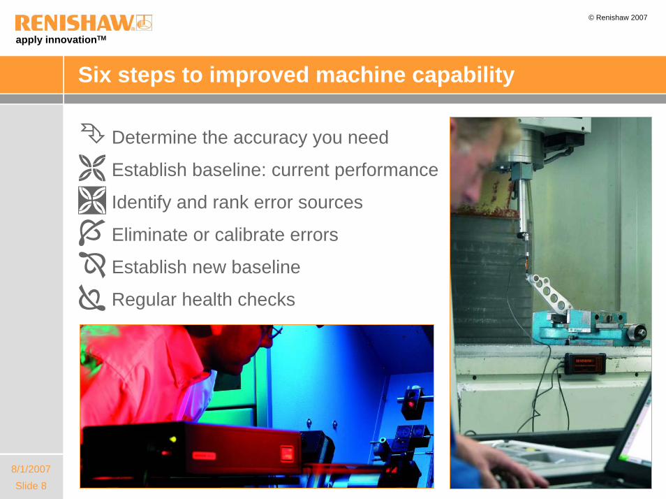
Six steps to improved machine capability
Determine the accuracy you need
Establish baseline: current performance
Identify and rank error sources
Eliminate or calibrate errors
Establish new baseline
Regular health checks
apply innovationTM
Slide 98/1/2007
© Renishaw 2007
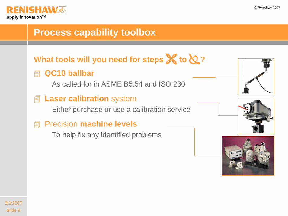
Process capability toolbox
What tools will you need for steps to ?QC10 ballbar
As called for in ASME B5.54 and ISO 230
Laser calibration systemEither purchase or use a calibration service
Precision machine levelsTo help fix any identified problems

apply innovationTM
Slide 108/1/2007
© Renishaw 2007
The machine performance measurement cycle
• Fix / calibrate, baseline, monitorPerform laser calibration and error compensation
Benchmark with a Ballbar test
MADE IN U.K. a b c d
SCALE 0.9997
27

apply innovationTM
Slide 118/1/2007
© Renishaw 2007
Agenda
• Goals of in-process inspection
• Productive Process PyramidTM
• Machine performance optimisation
• Calibration of 5-axis machine behaviour
• Impact of in-cycle process control
• The importance of temperature
• On-machine verification

apply innovationTM
Slide 128/1/2007
© Renishaw 2007
Example 5-axis machine configuration
Y-axis
A-axisC-axis
X-axis
Z-axis

apply innovationTM
Slide 138/1/2007
© Renishaw 2007
Error sources - alignment
Trunion alignmentZ axis
C-axis coupling AlignmentX-Z plane
Table alignmentX-Z plane
Trunion alignmentY axis
C-axis coupling alignment Y-Z plane
Table alignmentY-Z plane

apply innovationTM
Slide 148/1/2007
© Renishaw 2007
Error sources - position
C-axis centre Y-axisA-axis pivot Y-axisA-axis pivot Z-axisC-axis centre X-axis
Tableto A-axispivot
apply innovationTM
Slide 158/1/2007
© Renishaw 2007
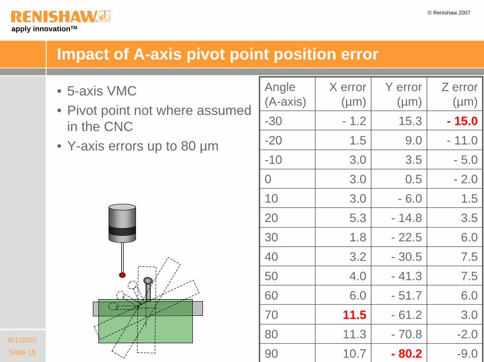
Impact of A-axis pivot point position error
Angle (A-axis)
X error (µm)
Y error (µm)
Z error (µm)
-30 - 1.2 15.3 - 15.0-20 1.5 9.0 - 11.0-10 3.0 3.5 - 5.00 3.0 0.5 - 2.010 3.0 - 6.0 1.520 5.3 - 14.8 3.530 1.8 - 22.5 6.040 3.2 - 30.5 7.550 4.0 - 41.3 7.560 6.0 - 51.7 6.070 11.5 - 61.2 3.080 11.3 - 70.8 -2.090 10.7 - 80.2 -9.0
• 5-axis VMC• Pivot point not where assumed
in the CNC• Y-axis errors up to 80 µm

apply innovationTM
Slide 168/1/2007
© Renishaw 2007
Compensation for machine behaviour
• Alignment errors do not change quickly, except in the event of a machine crash
– Check alignments and adjust if unacceptable
– Establish baseline and re-check when machine is re-calibrated and after a severe crash
• Position errors are affected by ambient temperature and heat generated during the machining process
– These positions can be established using a calibration process and then tracked using in-process checks in the machining program to improve the process capability
– The position of rotary axis centre-lines should be checked prior to performing precision finishing processes
apply innovationTM
Slide 178/1/2007
© Renishaw 2007
Agenda
• Goals of in-process inspection
• Productive Process PyramidTM
• Machine performance optimisation
• Calibration of 5-axis machine behaviour
• Impact of in-cycle process control
• The importance of temperature
• On-machine verification
apply innovationTM
Slide 188/1/2007
© Renishaw 2007
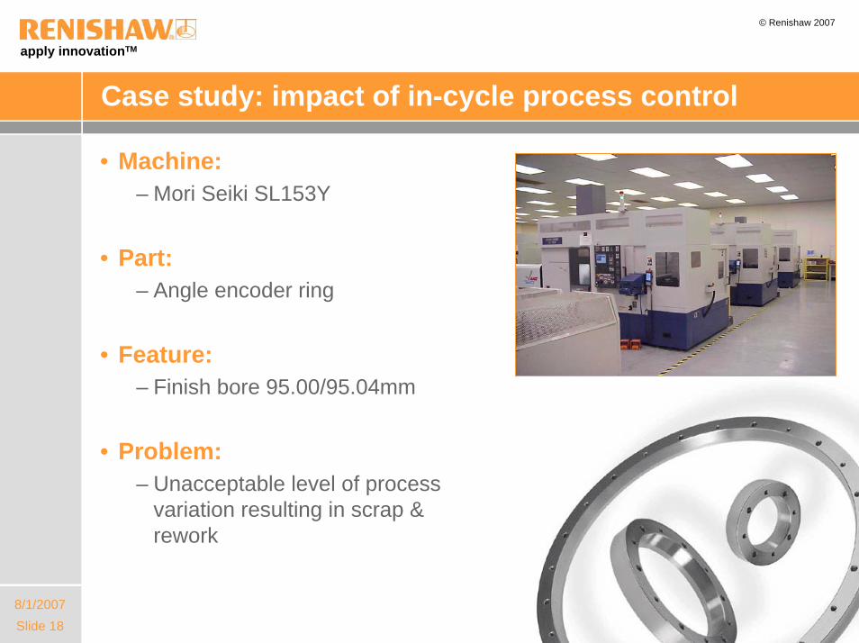
Case study: impact of in-cycle process control
• Machine:– Mori Seiki SL153Y
• Part:– Angle encoder ring
• Feature: – Finish bore 95.00/95.04mm
• Problem:– Unacceptable level of process
variation resulting in scrap & rework

apply innovationTM
Slide 198/1/2007
© Renishaw 2007
Case study: tests performed
• Baseline– Run 23 parts straight off without
process adjustment to establish inherent variation
• CMM process control– Measure part at end of process
and adjust finishing process on next part
• In-process gauging– Control roughing and finishing
processes in-cycle, adapting finishing cut based on semi-finished size with 75% offset correction
apply innovationTM
Slide 208/1/2007
© Renishaw 2007
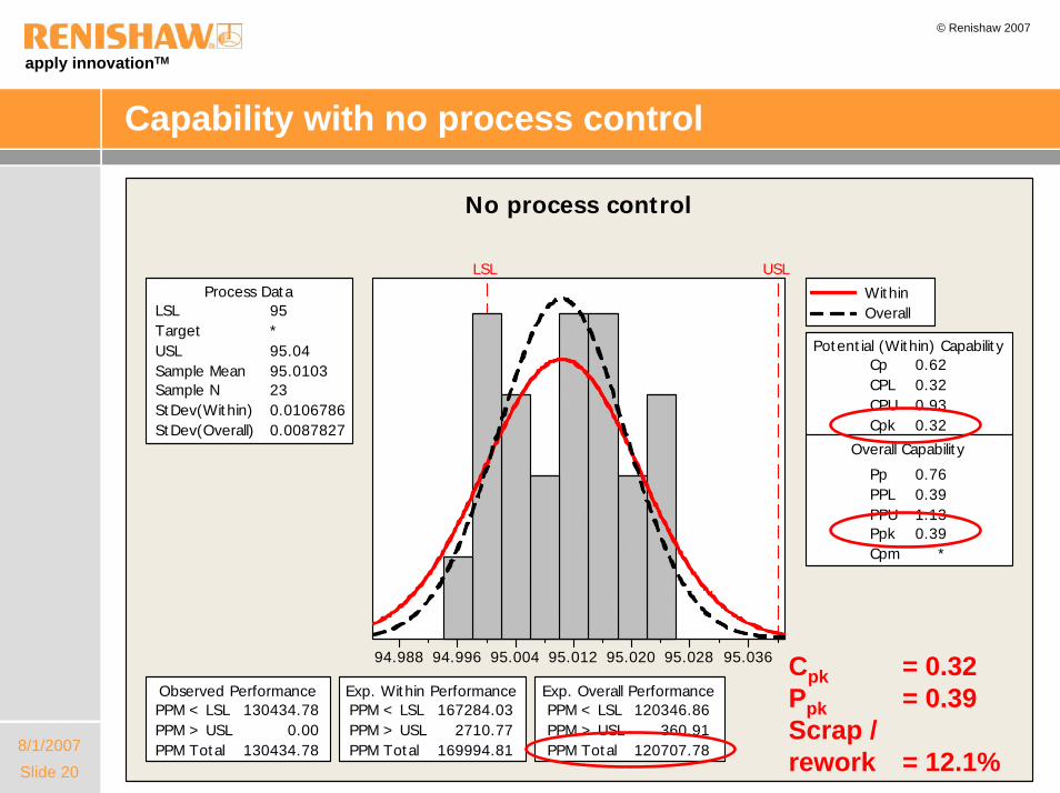
Capability with no process control
95.03695.02895.02095.01295.00494.99694.988
LSL USL
LSL 95Target *USL 95.04Sample Mean 95.0103Sample N 23StDev(Within) 0.0106786StDev(Overall) 0.0087827
Process Data
Cp 0.62CPL 0.32CPU 0.93Cpk 0.32
Pp 0.76PPL 0.39PPU 1.13Ppk 0.39Cpm *
Overall Capability
Potential (Within) Capability
PPM < LSL 130434.78PPM > USL 0.00PPM Total 130434.78
Observed PerformancePPM < LSL 167284.03PPM > USL 2710.77PPM Total 169994.81
Exp. Within PerformancePPM < LSL 120346.86PPM > USL 360.91PPM Total 120707.78
Exp. Overall Performance
WithinOverall
No process control
Cpk = 0.32Ppk = 0.39Scrap /rework = 12.1%
apply innovationTM
Slide 218/1/2007
© Renishaw 2007
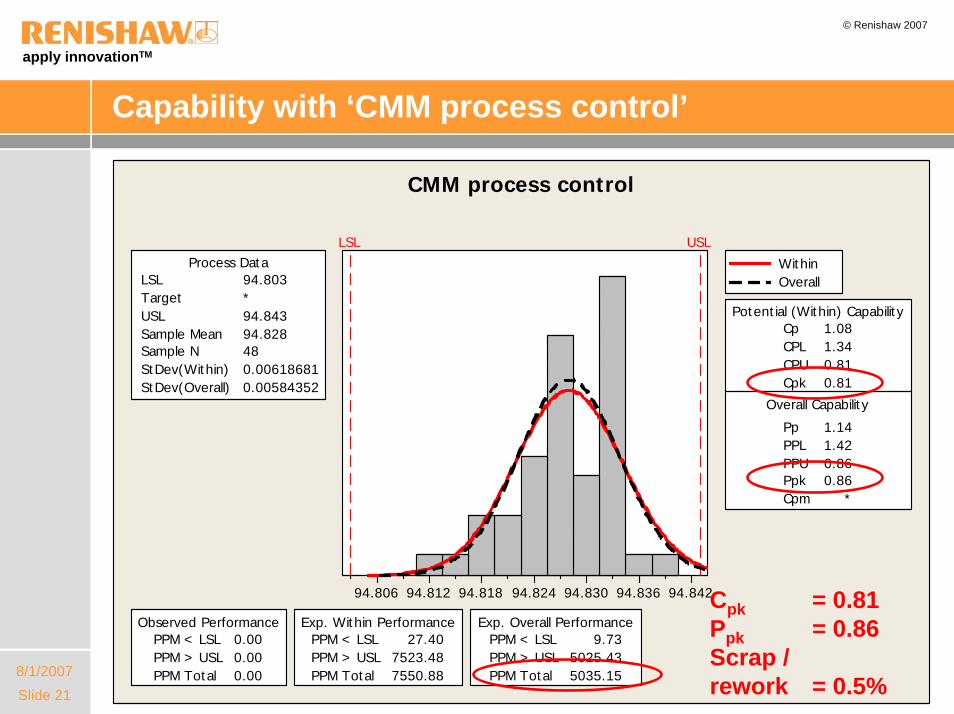
Capability with ‘CMM process control’
94.84294.83694.83094.82494.81894.81294.806
LSL USL
LSL 94.803Target *USL 94.843Sample Mean 94.828Sample N 48StDev(Within) 0.00618681StDev(Overall) 0.00584352
Process Data
Cp 1.08CPL 1.34CPU 0.81Cpk 0.81
Pp 1.14PPL 1.42PPU 0.86Ppk 0.86Cpm *
Overall Capability
Potential (Within) Capability
PPM < LSL 0.00PPM > USL 0.00PPM Total 0.00
Observed PerformancePPM < LSL 27.40PPM > USL 7523.48PPM Total 7550.88
Exp. Within PerformancePPM < LSL 9.73PPM > USL 5025.43PPM Total 5035.15
Exp. Overall Performance
WithinOverall
CMM process control
Cpk = 0.81Ppk = 0.86Scrap /rework = 0.5%
apply innovationTM
Slide 228/1/2007
© Renishaw 2007
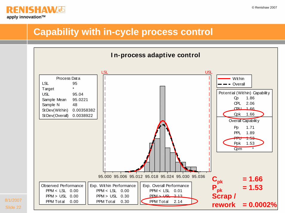
Capability with in-cycle process control
95.03695.03095.02495.01895.01295.00695.000
LSL USL
LSL 95Target *USL 95.04Sample Mean 95.0221Sample N 48StDev(Within) 0.00358382StDev(Overall) 0.0038922
Process Data
Cp 1.86CPL 2.06CPU 1.66Cpk 1.66
Pp 1.71PPL 1.89PPU 1.53Ppk 1.53Cpm *
Overall Capability
Potential (Within) Capability
PPM < LSL 0.00PPM > USL 0.00PPM Total 0.00
Observed PerformancePPM < LSL 0.00PPM > USL 0.30PPM Total 0.30
Exp. Within PerformancePPM < LSL 0.01PPM > USL 2.13PPM Total 2.14
Exp. Overall Performance
WithinOverall
In-process adaptive control
Cpk = 1.66Ppk = 1.53Scrap /rework = 0.0002%
apply innovationTM
Slide 238/1/2007
© Renishaw 2007
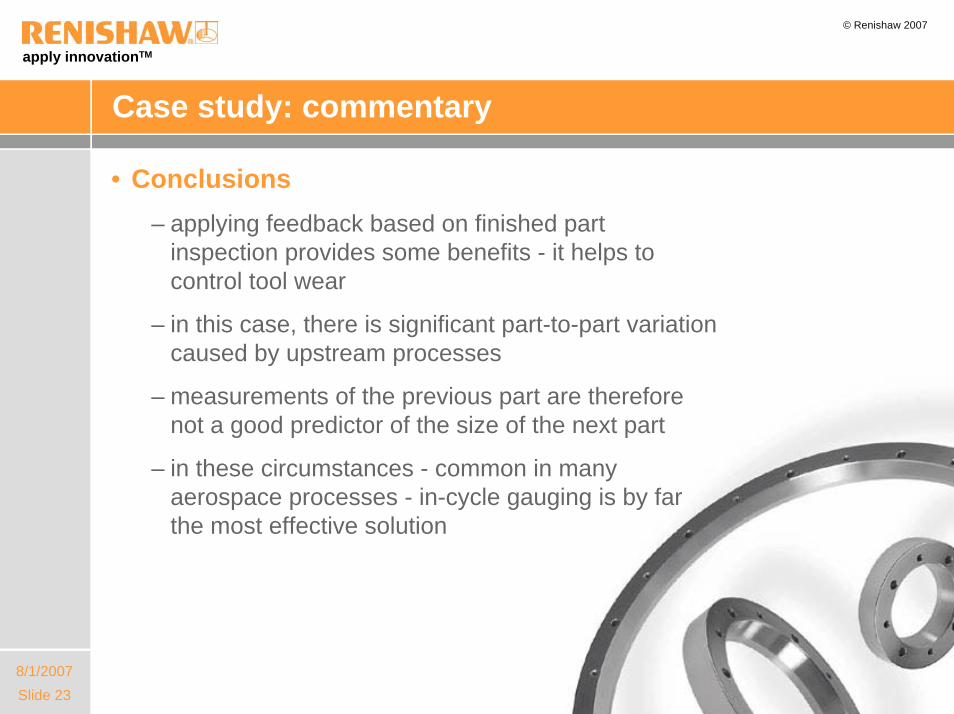
Case study: commentary
• Conclusions– applying feedback based on finished part
inspection provides some benefits - it helps to control tool wear
– in this case, there is significant part-to-part variation caused by upstream processes
– measurements of the previous part are therefore not a good predictor of the size of the next part
– in these circumstances - common in many aerospace processes - in-cycle gauging is by far the most effective solution
apply innovationTM
Slide 248/1/2007
© Renishaw 2007
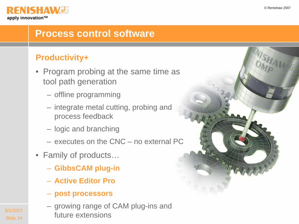
Process control software
Productivity+ • Program probing at the same time as
tool path generation– offline programming
– integrate metal cutting, probing and process feedback
– logic and branching
– executes on the CNC – no external PC
• Family of products…– GibbsCAM plug-in– Active Editor Pro– post processors– growing range of CAM plug-ins and
future extensions

apply innovationTM
Slide 258/1/2007
© Renishaw 2007
Productivity+TM Active Editor Pro
Rapid off-line programming and simulation of probing cycles
Selection of features to be measured from CAD
model
apply innovationTM
Slide 268/1/2007
© Renishaw 2007
Agenda
• Goals of in-process inspection
• Productive Process PyramidTM
• Machine performance optimisation
• Calibration of 5-axis machine behaviour
• Impact of in-cycle process control
• The importance of temperature
• On-machine verification

apply innovationTM
Slide 278/1/2007
© Renishaw 2007
The impact of temperature
• Thermal effects can dominate
– if the material temperature is uncertain, then the level of thermal growth may swamp the tolerance that is being targeted
– ambient temperature in many shops varies from cold (perhaps 15 ºC) to hot (> 30 ºC)
– on many large parts, temperature is a significant or dominant uncertainty
% of tolerance consumed by thermal growth (11 ppm/ ºC) where temperature varies by ±5 ºC
Significance of thermal growth

apply innovationTM
Slide 288/1/2007
© Renishaw 2007
Maintaining thermal stability
Y
Z
• Machine tools also generate heat as they work– heat flows distort machine structure
• The fastest rate of change occurs when the machine starts and stops
• Keep the machine warm– run warm-up cycles if machine has
been idle
– run ‘exercise cycles’ to keep the machine warm during short idle periods
• Avoid sudden temperature change– windows and doors
Fastest distortion
when machine starts or stops
Z drift
50 um
100 um
150 um
1 hr 2 hr 3 hr

apply innovationTM
Slide 298/1/2007
© Renishaw 2007
Renishaw’s approach
• Controlled thermal environment…– control of ambient temperature to ±2 ºC
– modern machines with through ball-screw and through tool coolant
– coolant chiller systems
– parts mostly < 100 mm
– thermal growth is not a significant source of part-to-part variation in most cases
• Yet we still use artefacts…– artefacts provide TRACEABILITY
– allows elimination of post-process measurement
apply innovationTM
Slide 308/1/2007
© Renishaw 2007
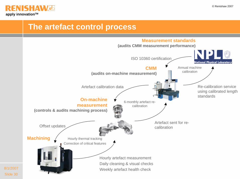
The artefact control process
Machining
On-machinemeasurement
(controls & audits machining process)
CMM(audits on-machine measurement)
Hourly artefact measurementDaily cleaning & visual checksWeekly artefact health check
Offset updates
Hourly thermal trackingCorrection of critical features
Artefact sent for re-calibration
Artefact calibration data
6-monthly artefact re-calibration
Measurement standards(audits CMM measurement performance)
Annual machine calibration
Re-calibration service using calibrated length standards
ISO 10360 certification

apply innovationTM
Slide 318/1/2007
© Renishaw 2007
Agenda
• Goals of in-process inspection
• Productive Process PyramidTM
• Machine performance optimisation
• Calibration of 5-axis machine behaviour
• Impact of in-cycle process control
• The importance of temperature
• On-machine verification
apply innovationTM
Slide 328/1/2007
© Renishaw 2007
Verifying the process using on-machine probing
• Verification can be combined with control of finishing process
– artefact measured first to calibrate current machine thermal condition
– comparative measurement gives traceability and is independent of machine tool measurement accuracy
– part measured using gauging points on surfaces - critical features only
– thermal effects identified by artefact are compensated when updating the process variables
Measurement of the first part in a batch on RAMTIC
Video_9.6_RAMTIC_1st_part.mpg
apply innovationTM
Slide 338/1/2007
© Renishaw 2007
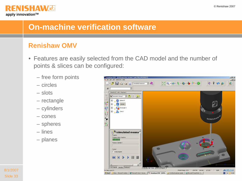
On-machine verification software
Renishaw OMV
• Features are easily selected from the CAD model and the number of points & slices can be configured:
– free form points– circles– slots– rectangle– cylinders– cones– spheres– lines– planes

apply innovationTM
Slide 348/1/2007
© Renishaw 2007
On-machine verification software
Renishaw OMV
• Rapid feature selection from CAD model
• Simulation of probing cycles• Requires PC to analyse data
gathered on the machine
NEW multi-axis version
• Display points taken in multiple orientations against the CAD model
apply innovationTM
Slide 358/1/2007
© Renishaw 2007
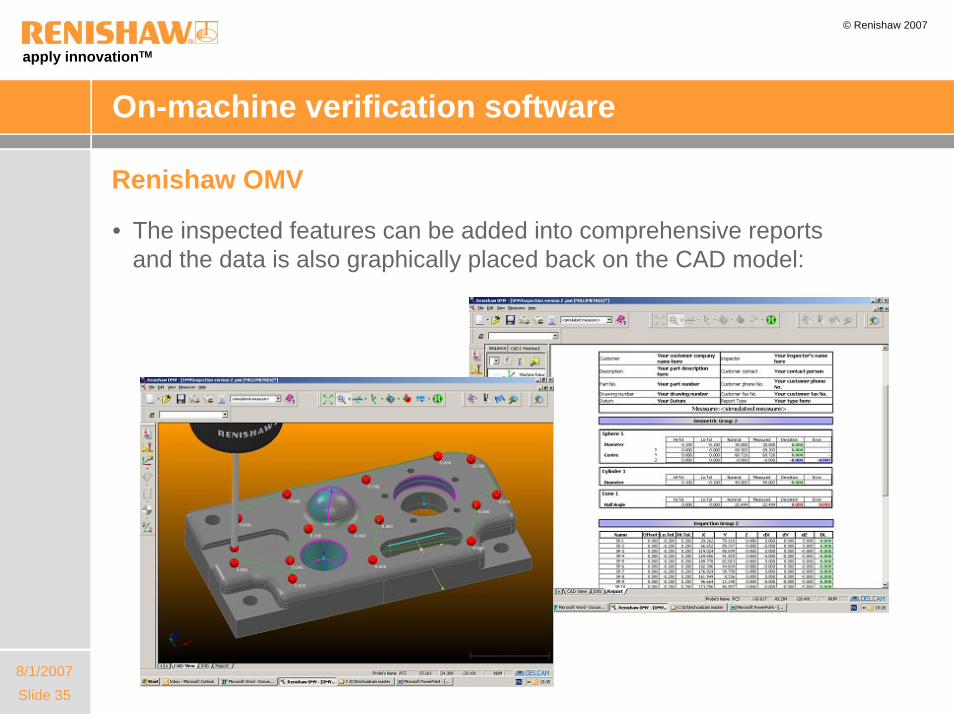
On-machine verification software
Renishaw OMV
• The inspected features can be added into comprehensive reports and the data is also graphically placed back on the CAD model:

apply innovationTM
Slide 368/1/2007
© Renishaw 2007
apply innovation