Using Molecular Dynamics to Model the Stacking Behaviour ...
9
Using Molecular Dynamics to Model the Stacking Behaviour of Perylene Bisimide Derivatives in Aromatic Solvent M. Hollfelder, S. Gekle published in NIC Symposium 2016 K. Binder, M. M¨ uller, M. Kremer, A. Schnurpfeil (Editors) Forschungszentrum J ¨ ulich GmbH, John von Neumann Institute for Computing (NIC), Schriften des Forschungszentrums J ¨ ulich, NIC Series, Vol. 48, ISBN 978-3-95806-109-5, pp. 105. http://hdl.handle.net/2128/9842 c 2016 by Forschungszentrum J¨ ulich Permission to make digital or hard copies of portions of this work for personal or classroom use is granted provided that the copies are not made or distributed for profit or commercial advantage and that copies bear this notice and the full citation on the first page. To copy otherwise requires prior specific permission by the publisher mentioned above.
Transcript of Using Molecular Dynamics to Model the Stacking Behaviour ...
Using Molecular Dynamics to Model theStacking Behaviour of Perylene Bisimide
Derivatives in Aromatic Solvent
M. Hollfelder, S. Gekle
published in
NIC Symposium 2016K. Binder, M. Muller, M. Kremer, A. Schnurpfeil (Editors)
Forschungszentrum Julich GmbH,John von Neumann Institute for Computing (NIC),Schriften des Forschungszentrums Julich, NIC Series, Vol. 48,ISBN 978-3-95806-109-5, pp. 105.http://hdl.handle.net/2128/9842
c© 2016 by Forschungszentrum JulichPermission to make digital or hard copies of portions of this work forpersonal or classroom use is granted provided that the copies are notmade or distributed for profit or commercial advantage and that copiesbear this notice and the full citation on the first page. To copy otherwiserequires prior specific permission by the publisher mentioned above.
Using Molecular Dynamics to Model the StackingBehaviour of Perylene Bisimide Derivatives in Aromatic
Solvent
Manuel Hollfelder and Stephan Gekle
Biofluid Simulation and Modeling, University of Bayreuth, 95444 Bayreuth, GermanyE-mail: [email protected]
Using the power of present-day supercomputers makes it possible to solve Newton’s equa-tions of motion numerically, even for large systems. Molecular Dynamics provides a powerfulsimulation method to get insight in the behaviour of molecules under many conditions whenconsidering atoms as charged solid spheres and hiding the quantum mechanics in effective po-tentials. We use this method to characterise the physical properties of different systems, e.g.polymers, water, organic and inorganic molecules.As an example of our work, we present a model of the π-π stacking dynamics of a perylenebisimide molecule when solvated in aromatic solvents. Our calculations show that the transi-tion from the open (unstacked) to the stacked configuration is hindered by a small free energybarrier of approx. 1 kBT in the aromatic solvent toluene. The origin of this barrier is tracedback to π-π interactions between perylene and the aromatic solvent which are very similar innature to those between two PBI monomers. The stacking process proceeds in three phasesvia two well-defined transition states: (i) in the first phase, the two PBI molecules share partof their respective solvation shells forming the first transition state. Further approach needs tosqueeze out the shared solvent layer thus creating the energy barrier. (ii) After removal of theseparating solvent the two PBIs form a second transition state with one monomer located at arandom position in the other’s solvation shell. (iii) Finally, the two PBIs slide on top of eachother into their final stacked position.
1 Introduction
Newton’s equations of motion cannot be solved analytically for large systems. The termlarge system is, however, misleading since every system above two particles must be con-sidered of this type. Therefore, modelling atoms as solid and charged spheres in the frame-work of Molecular Dynamics leads only to new results if one takes the possibility of numer-ical calculations into account. Nowadays supercomputers allow us to solve the equationsof Molecular Dynamics simulations for truly large systems, e.g. number of atoms above20 000, within finite time.
Using the computation time granted by the John von Neumann Institute for Computing(NIC) and provided on the supercomputer JUROPA at Julich Supercomputing Centre (JSC)we model different molecules, e.g. polymers, organic and inorganic molecules, water,and derive models of interaction or calculate physical properties of these molecules. Thisarticle gives a brief summary of our work and presents as an example results obtained fromnumerical calculations of an organic dimer consisting of two covalently linked perylenebisimide molecules (PBM) using highly parallelised supercomputers1.
Sec. 2 summarises the motivation of our investigations. After introducing briefly themethods in Sec. 3, we use Sec. 4.1 to characterise the structure of the solvation shell arounda single PBM when solvated in toluene as a typical aromatic solvent. In Sec. 4.2 we then
105
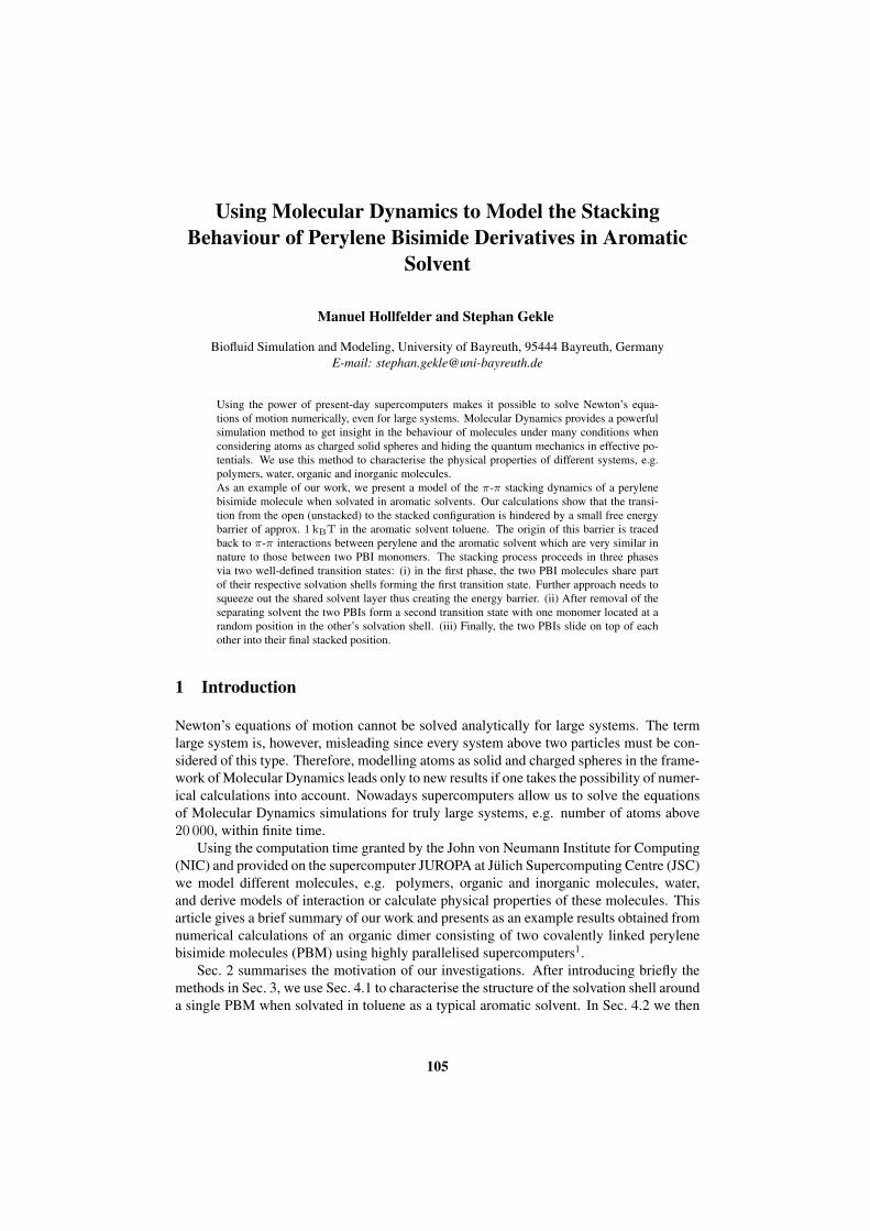
(a) (b) (c)
Figure 1. (a) Chemical structure of the investigated perylene bisimide dimer molecule. (b) Snapshot of an un-stacked (OPEN) state and (c) snapshot of a stacked (STACK) configuration. The solvent toluene is omitted forclarity.
present the free energy profiles for the dimer solvated in toluene which governs the stackingtransition. In Sec. 4.3 we describe the full stacking pathway which proceeds from the opento the stacked configuration via two well-defined transition states.
2 Motivation
Molecules based on derivatives of perylene are a widely used material for many differentpurposes: they have useful optical properties because their emission colour can be adjustedover a wide range of the visible spectrum, they are used as highly sensitive sensors andshow n-type conduction making them suitable for organic transistors and optoelectronicdevices in general. Furthermore, molecules based on perylene derivatives are considered apromising candidate for building highly efficient organic solar cells.
Given these numerous applications, perylene derivatives have been intensively inves-tigated both experimentally and computationally in the recent past. One of their salientcharacteristics is a tendency to form large tower-like aggregates (stacks) of molecules ashas been demonstrated by experiments and ab initio molecular dynamics simulations. Thisstacking behaviour can be traced back to the interactions of the π-orbitals and has great in-fluence on the properties of the materials as it dramatically changes, e.g., the efficiency ofenergy and charge transfer processes. The static structure of these stacks has been wellcharacterised: in the stacked state the perylenes remain mostly planar with the distancebetween the two planes being around 0.35 nm; the perylene axes are tilted by approx.45° with respect to each other and the free energy gained from stacking is of the order of15 kJ/mol depending on the exact chemical structure of the perylene derivative as deter-mined by linear free energy relationships in conjunction with UV/Vis spectroscopy2.
A systematic investigation of the dynamic transition pathway from the open (un-stacked) to the stacked state, however, has not been conducted so far. Here, we have
106

investigated the transition dynamics considering a perylene bisimide dimer solvated intoluene by Molecular Dynamics (MD) simulations. The investigated structure consists oftwo perylene bisimide monomers (PBM) and is shown in Fig. 1 (a). Both monomers areconnected by an alkane chain containing furthermore oxygen, nitrogen and two aromaticrings. On the other side of the PBM two C7H15 chains are present. We consider thesolvent toluene representing a prototypical aromatic solvent. The toluene-solvated systemhas recently been investigated by fluorescence spectroscopy3, 4. The unstacked (OPEN) andstacked (STACK) configurations are well reproduced by our MD simulations as shown inFig. 1 (b) and (c). We find the distance of the planes defined by the (almost perfectly) planarPBMs to be 0.36 nm which is in good agreement with values obtained from experimentsand earlier MD simulations5.
3 Simulation Methods
Classical Molecular Dynamics simulations were run with Gromacs and the Gromos 53a6force field was used. This means that the parameters of the bonds, harmonic spring con-stants, Lennard-Jones parameters etc. follow a parameter set of typical bonding values andinteractions which is itself consistent. Building new molecules reduces to combining thecorrect parameters for the bonds between the atoms and assigning charges to the atoms.These force field topologies were automatically calculated for the perylene derivatives us-ing Automated Force Field Topology Builder (ATB) and Repository. The force field filefor the solvent toluene was calculated using PRODRG. United-atom force field topologieswere used for the simulations which means that hydrogen atoms and carbon atoms, e.g.for alkane chains, are combined to super-atoms to reduce the necessary computation time.The visual analysis of the molecular structure files and trajectories was carried out usingVMD.
For the simulations the dimer was solvated in a rectangular box with 1000 toluenemolecules. After energy minimisation and NVT equilibration, the final runs were simu-lated as NPT ensembles at 300 K and 1 bar. In order to investigate the general behaviourand stacking of the dimer, simulations were started with different starting configurationsof the atoms’ positions and velocities. Every simulation was stopped as soon as stackingoccurred.
For the free energy calculations in Sec. 4.2 we use umbrella sampling where the dis-tance between the centres of mass of the PBMs was chosen as a reaction coordinate anddifferent states along that coordinate were created using the Gromacs pull code. Afterequilibration the simulations were simulated as NPT ensembles for each window at 300 Kand 1 bar. For the bias potential the umbrella potential implemented in the Gromacs pack-age was used and simulations with different spring constants were started. The free energyprofile was calculated using the Weighted Histogram Analysis Method implemented inGromacs as g wham.
4 Results and Discussion
4.1 Static Solvation Shell for Toluene
We first analyse the static structure of the toluene solvation shell around a single PBM ofthe dimer in the OPEN state. We find a clear first solvation shell whose time averaged
107
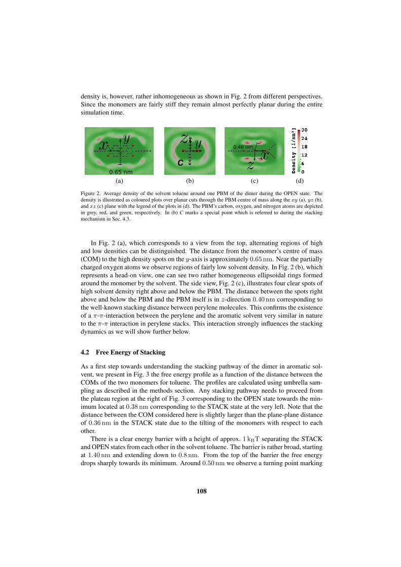
density is, however, rather inhomogeneous as shown in Fig. 2 from different perspectives.Since the monomers are fairly stiff they remain almost perfectly planar during the entiresimulation time.
0.65 nm
(a)
C
(b)
0.40 nm
(c) (d)
Figure 2. Average density of the solvent toluene around one PBM of the dimer during the OPEN state. Thedensity is illustrated as coloured plots over planar cuts through the PBM centre of mass along the xy (a), yz (b),and xz (c) plane with the legend of the plots in (d). The PBM’s carbon, oxygen, and nitrogen atoms are depictedin grey, red, and green, respectively. In (b) C marks a special point which is referred to during the stackingmechanism in Sec. 4.3.
In Fig. 2 (a), which corresponds to a view from the top, alternating regions of highand low densities can be distinguished. The distance from the monomer’s centre of mass(COM) to the high density spots on the y-axis is approximately 0.65 nm. Near the partiallycharged oxygen atoms we observe regions of fairly low solvent density. In Fig. 2 (b), whichrepresents a head-on view, one can see two rather homogeneous ellipsoidal rings formedaround the monomer by the solvent. The side view, Fig. 2 (c), illustrates four clear spots ofhigh solvent density right above and below the PBM. The distance between the spots rightabove and below the PBM and the PBM itself is in z-direction 0.40 nm corresponding tothe well-known stacking distance between perylene molecules. This confirms the existenceof a π-π-interaction between the perylene and the aromatic solvent very similar in natureto the π-π interaction in perylene stacks. This interaction strongly influences the stackingdynamics as we will show further below.
4.2 Free Energy of Stacking
As a first step towards understanding the stacking pathway of the dimer in aromatic sol-vent, we present in Fig. 3 the free energy profile as a function of the distance between theCOMs of the two monomers for toluene. The profiles are calculated using umbrella sam-pling as described in the methods section. Any stacking pathway needs to proceed fromthe plateau region at the right of Fig. 3 corresponding to the OPEN state towards the min-imum located at 0.38 nm corresponding to the STACK state at the very left. Note that thedistance between the COM considered here is slightly larger than the plane-plane distanceof 0.36 nm in the STACK state due to the tilting of the monomers with respect to eachother.
There is a clear energy barrier with a height of approx. 1 kBT separating the STACKand OPEN states from each other in the solvent toluene. The barrier is rather broad, startingat 1.40 nm and extending down to 0.8 nm. From the top of the barrier the free energydrops sharply towards its minimum. Around 0.50 nm we observe a turning point marking
108

a change in the curvature of the free energy curve. Finally, for distances smaller than0.38 nm the free energy rises steeply which is caused by unfavourable squeezing of thePBMs during the stacked state.
The free energy difference between the minimum identified with the STACK state andthe OPEN state with constant free energy for distances beyond 1.40 nm is approximately5.2 kBT corresponding to 13 kJ/mol. This is in good agreement with values obtainedfrom UV/Vis experiments for the aggregation of perylene bisimide: for a slightly differentstructure of the PBMs (two additional benzene molecules and no connecting carbon chain)the free energy change was obtained as 15.8 kJ/mol for the solvent toluene2.
The density profiles of the toluene solvation shells around the monomers (Fig. 2) allowa physical interpretation of the distinct features observed in the free energy profile in thetransition region between 1.4 nm and 0.8 nm. Noting from Fig. 2 (b) and (c) that thesolvation shells are located at distances between 0.40 nm in z-direction and 0.65 nm in y-direction, the first contact of the solvation shells is expected to occur for distances between0.8 nm and 1.3 nm (depending on the relative orientation of the PBMs during approach)which corresponds closely to the width and position of the energy barrier for toluene.After contact, further approach of the PBMs is only possible if (at least) one of the PBMsloses part of its solvation shell and the two PBMs further on “share” solvent molecules.Scraping off the solvation shell clearly requires energy in the case of the solvent toluenethus explaining the observed energy barrier. For distances smaller than about 0.7 nm thePBMs start interacting directly leading to a rapid drop towards the STACK state whichrepresents the absolute minimum of the free energy.
-4
-3
-2
-1
0
1
2
0.4 0.6 0.8 1 1.2 1.4 1.6 1.8 2 2.2
fre
e e
ne
rgy [
kBT
]
toluene
OPEN
STACK energy barrier
COM distance [nm]
Figure 3. Free energy change as a function of the centre of mass (COM) distance between both PBMs of thedimer for the solvent toluene (red). The states STACK/OPEN and the energy barrier for toluene are marked andthe energy profiles are shifted against each other for clarity.
109

0
0.5
1
1.5
2
2.5
3
3.5
4
4.5
-100 -90 -80 -70 -60 -50 -40 -30 -20 -10 0
CO
M d
ista
nce [nm
]
time [ns]
stacking attempts
OPEN STACK
(a)
0
100
200
300
400
500
600
0.4 0.6 0.8 1.0 1.2 1.4
absolu
te fre
quency
COM distance [nm]
TS1
STACK
TS2
(b)
Figure 4. (a) The COM distance between both PBMs with stacking at t = 0 ns. The distance decreases severaltimes to values between 0.80 nm and 1.00 nm (marked spots) without causing a change to the stacked stateSTACK which is characterised by an average COM distance of about 0.38 nm. (b) Histogram over COM dis-tances for the transition from OPEN to STACK in the solvent toluene. Only frames < 2000 ps before stackingare taken into account. The peak around 1.00 nm corresponds to the transition state TS1, the second one around0.50 nm to TS2 and the third one around 0.38 nm to the state STACK.
4.3 Dynamic Stacking Pathway of Perylene Bisimide in Toluene
We now turn to the actual stacking pathway for toluene as an example of an aromaticsolvent. Fig. 4 (a) shows the COM distance of the two monomers as a function of time fora typical trajectory before and during the stacking process. The origin of time at t = 0 nshas been located at the stacking transition which clearly separates the STACK from theOPEN configurations. Before the actual transition, however, the distance decreases severaltimes to values between 0.80 nm and 1.00 nm but without continuing to the final stackedstate. These “failed attempts” are a consequence of the energy barrier seen in Fig. 3 whichcan be overcome by thermal fluctuations only in a small number of cases.
We now focus more closely on the actual stacking process. The most notable feature aretwo regions of fairly constant COM distance during the stacking of the monomers duringthe simulations. These regions correspond to two well-defined transition states which weshall denominate in the following as TS1 and TS2, respectively. These transition states canbe found with variable time duration in all our simulations during the stacking process. Togive a full picture, we present in Fig. 4 (b) a histogram taken over all simulations duringthe last 2000 ps before stacking. The value of 2000 ps was estimated from the averagetime the stacking process lasts during the different simulations. Beside the expected peakcorresponding to the STACK state at 0.38 nm, the histogram clearly shows two furtherpeaks: a broad first peak centred around 1.0 nm and a second sharper one at about 0.50 nm.The COM distances where these peaks occur correspond to the transition states TS1 andTS2 and are evidence of the general nature of the transition states.
The picture that thus emerges is a stacking pathway consisting of three consecutivephases. In the first phase both PBMs approach each other closely until the respective sol-vation shells first come into contact and subsequently merge to form the first transition stateTS1. In this state, which is illustrated in Fig. 5 (a), the two monomers share part of theirrespective solvation shell (green solvent molecules). Further approach would require the
110

(a) (b) (c)
Figure 5. The different states during the stacking process illustrated with the solvation shell (dashed lines) aroundthe PBMs. (a) View of the first transition state TS1 in which the PBMs share part of their solvation shells (sharedsolvent has blue colour). (b) Second transition state TS2 where the PBMs replace the solvent by themselves andonly some solvent remains next to them (blue molecules) which stabilises this state. (c) Final stacked state.
complete removal of the shared solvent molecules which is connected to the energy bar-rier as observed in Fig. 3. In most cases, the dynamics continues without transcending thebarrier and the PBMs separate again (corresponding to the “failed attempts” in Fig. 4). Insome cases, however, the energy barrier can be overcome by adequate thermal fluctuationsand the dynamics continues to the second phase.
In the second phase, the solvent between the PBMs is expelled, the PBMs approachmore closely, and the first monomer becomes part of the second monomer’s solvationshell (and vice versa). In TS2 there are still some solvent molecules present as shownin Fig. 5 (b) by the green solvent molecules. These stabilise TS2 by their π-π interactionswith the perylene. The existence of TS2 furthermore reflects itself in the slightly flatter partof the free energy profile around 0.50 nm in Fig. 3. Both monomers arrange themselvessuch that the normal vectors to the PBM planes are parallel. For the position of the twoPBMs relative to each other we find the most probable angles around 47° of the connectingCOM and the normal vector showing that the monomers approach each other via a well-defined “channel” through the point marked A in Fig. 2 (b). The time span during whichTS2 exists strongly varies with the second monomer’s exact location and the stabilisingsolvent molecules. Once TS2 has been reached, however, the system is already situated onthe steep downward slope of the free energy which makes final stacking inevitable.
In the third and final phase, the second monomer revolves around the first one in orderto find its final stacked position with the two PBM planes lying right on top of each other,possessing the well-known COM distance of 0.38 nm and a joint solvation shell as shownin Fig. 5 (c).
5 Conclusion
In conclusion, we have elucidated the dynamic stacking pathway of perylene bisimidedimers solvated in toluene using Molecular Dynamics simulations in combination withfree energy calculations. In toluene, the stacked and unstacked states are well separated bya free energy barrier of approx. 1 kBT which is due to the fairly rigid solvation shells thatthe aromatic solvent forms around each perylene bisimide monomer. During the stacking
111

transition this barrier is overcome in three phases: (i) after the initial approach and the firstcontact of the solvation shells, the two monomers form a metastable first transition state(TS1) in which they share part of their respective solvation shells. Further approach re-quires the removal of the shared region of the solvation shell thus explaining the observedenergy barrier. (ii) If thermal fluctuations allow the system to overcome this energy bar-rier, the system forms a second transition state (TS2) in which the interjacent solvent of theshared solvation shell is expelled and substituted by one of the perylene monomers them-selves which, loosely speaking, “solvate themselves” in this state. (iii) In the last step themonomers revolve around each other until the two planes lie on top of each other whichrepresents the final stacked configuration.
A central result of our investigations is that the stacking pathway is mainly determinedby the ability of the aromatic solvent to form π-π-interactions with the solute very similarto those formed between the perylenes themselves. This leads to an energy barrier whichmust be overcome before the system can form the familiar stacks.
Acknowledgements
The authors gratefully acknowledge the computing time granted by the John von NeumannInstitute for Computing (NIC) and provided on the supercomputer JUROPA at Julich Su-percomputing Centre (JSC).
Financial support comes from the Volkswagen Foundation in the framework of theLichtenberg program and from the Graduiertenkolleg 1640. Further thanks are owed toFlorian Spreitler, Jurgen Kohler and Mukundan Thelakkat for helpful discussions.
References
1. M. Hollfelder and S. Gekle, Dynamic Stacking Pathway of Perylene Dimers in Aro-matic and Nonaromatic Solvents, The Journal of Physical Chemistry B, 119, no. 32,10216–10223, 2015, PMID: 26186499.
2. Z. Chen, B. Fimmel, and F. Wurthner, Solvent and Substituent Effects on Aggrega-tion Constants of Perylene Bisimide π-Stacks - a Linear Free Energy RelationshipAnalysis, Org. Biomol. Chem., 10, 5845–5855, 2012.
3. F. Spreitler, M. Sommer, M. Thelakkat, and J. Kohler, Conformational Dynam-ics of Di-(Perylene Bisimide Acrylate) and Its Footprints in Steady-State, Time-Resolved, and Fluorescence-Correlation Spectroscopy, Phys. Chem. Chem. Phys.,14, 7971–7980, 2012.
4. F. Spreitler, M. Sommer, M. Hollfelder, M. Thelakkat, S. Gekle, and J. Kohler, Un-ravelling the Conformations of Di-(Perylene Bisimide Acrylate) by Combining Time-Resolved Fluorescence-Anisotropy Experiments and Molecular Modelling, Phys.Chem. Chem. Phys., 16, 25959–25968, Nov. 2014.
5. V. Marcon, J. Kirkpatrick, W. Pisula, and D. Andrienko, Supramolecular Structure ofPerylene Tetracarboxdiimides, phys. stat. sol. (b), 245, no. 5, 820–824, May 2008.
112