Using Labview Full Development Software with to Real...
20
For additional documentation, please visit www.beckhoffautomation.com For further assistance, please contact Beckhoff USA support at [email protected] BECKHOFF www.beckhoffautomation.com Application Notes Beckhoff Automation 12150 Nicollet Avenue South Burnsville, MN 55337 Phone: + 1 952 / 890 0000 Fax: + 1 952 / 890 2888 [email protected] Using Labview Full Development Software with Beckhoff Ethernet/IP Hardware for Connection to Real World Digital and Analog I/O BK-AppNote-013 1.1 18 October 2007 1.0 25 June 2007 This document covers and explains how to create a National Instru- ments Labview application using a Beckhoff EthernetIP bus coupler and standard bus terminals from Beckhoff Automation to interface with real world inputs and outputs.
Transcript of Using Labview Full Development Software with to Real...
For additional documentation,
please visit
www.beckhoffautomation.com
For further assistance, please
contact Beckhoff USA support
BECKHOFFwww.beckhoffautomation.com
Application Notes
Beckhoff Automation
12150 Nicollet Avenue South
Burnsville, MN 55337
Phone: + 1 952 / 890 0000
Fax: + 1 952 / 890 2888
Using Labview Full Development Software with
Beckhoff Ethernet/IP Hardware for Connection
to Real World Digital and Analog I/O
BK-AppNote-013
1.1
18 October 2007
1.0
25 June 2007
This document covers and explains how to create a National Instru-
ments Labview application using a Beckhoff EthernetIP bus coupler and
standard bus terminals from Beckhoff Automation to interface with real
world inputs and outputs.

16 April 2008 Beckhoff Application Notes 2
Using Labview Full Development Software with Beckhoff Ethernet/IP Hardware for Connection to Real World Digital and
Analog I/O
Overview
Supporting Documents and References
BK9105 Documentation
ftp://ftp.beckhoff.com/Document/BusTermi/BCoupler/BK9105e.chm
Creating and Using an Additional Task
http://www.beckhoffautomation.com/usa/applicat/appnotes.htm
Sample Files
Key Concepts
The Beckhoff I/O used for this Labview application note is shown below. The analog out-
puts are +/- 10Vdc. Wire the analog outputs into the analog inputs which are also +/- 10
Vdc.
Sample Files Using the Sample Files
National Instruments Labview
Demo.tsm
Open using the Beckhoff System
Manager
Demo2.vi Open in Labview as needed
Beckhoff National Instruments Demo
Labview.vi
Open in Labview as a finished Lab-
view project example using Beckhoff
I/O Hardware

16 April 2008 Beckhoff Application Notes 3
Using Labview Full Development Software with Beckhoff Ethernet/IP Hardware for Connection to Real World Digital and
Analog I/O
The module LEDs let you know when a digital output is being turned on. A temporary
jumper wire works fine to jump 24Vdc to the KL1104’s digital input channels.

16 April 2008 Beckhoff Application Notes 4
Using Labview Full Development Software with Beckhoff Ethernet/IP Hardware for Connection to Real World Digital and
Analog I/O
Procedure
Start Labview VI and Add an ActiveX Container
Start a new Labview VI. Labview has two main components to each virtual instrument
(VI): the Front Panel and the Diagram. The first thing needed on the front panel is an
ActiveX container. Right-Click anywhere on the front panel to bring up the controls pallet
(if it is not already visible). Go to the .NET and ActiveX pallet and choose the ActiveX
Container icon.
Move the mouse over to the front panel and click ActiveX Container. There should be an
empty ActiveX container on the screen.

16 April 2008 Beckhoff Application Notes 5
Using Labview Full Development Software with Beckhoff Ethernet/IP Hardware for Connection to Real World Digital and
Analog I/O
Insert an ActiveX Object
Next, an ActiveX Control needs to be placed inside the container. Right-click the mouse
inside the ActiveX container. A pop-up window appears. Select Insert ActiveX Object...
A new pop-up window appears with a list of all available ActiveX controls. Click AdsOcx
Control, then OK
Move to the Labview Diagram window. The AdsOcx control should appear in the diagram.
This is the graphical reference to the Beckhoff AdsOcx control.

16 April 2008 Beckhoff Application Notes 6
Using Labview Full Development Software with Beckhoff Ethernet/IP Hardware for Connection to Real World Digital and
Analog I/O
Add Properties
Next, add blocks to expose the Properties and Methods the AdsOcx control allows to
interface within Labview. Right-click in an open area of the Diagram Window to display
the Functions pallet (if it is not already being displayed). Hover the mouse over the Con-
nectivity pallet item. This displays the Connectivity pallet. Hover the mouse over the
ActiceX pallet item. This displays all available ActiveX tools. Choose the Property Node
icon by clicking on it.
Add the AdsAmsServerNetId and AdsAmsServerPort Properties
Place the mouse on the Properties item in the pop-up and Left-Click again to see a list of
all items that are available.
Select AdsAmsServerNetId and Left-Click it to replace the item that was previously
shown when the Property Node box was first wired to the AdsOcx Property Node icon.
16 April 2008 Beckhoff Application Notes 7
Using Labview Full Development Software with Beckhoff Ethernet/IP Hardware for Connection to Real World Digital and
Analog I/O
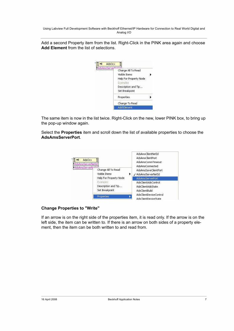
Add a second Property item from the list. Right-Click in the PINK area again and choose
Add Element from the list of selections.
The same item is now in the list twice. Right-Click on the new, lower PINK box, to bring up
the pop-up window again.
Select the Properties item and scroll down the list of available properties to choose the
AdsAmsServerPort.
Change Properties to "Write"
If an arrow is on the right side of the properties item, it is read only. If the arrow is on the
left side, the item can be written to. If there is an arrow on both sides of a property ele-
ment, then the item can be both written to and read from.
16 April 2008 Beckhoff Application Notes 8
Using Labview Full Development Software with Beckhoff Ethernet/IP Hardware for Connection to Real World Digital and
Analog I/O
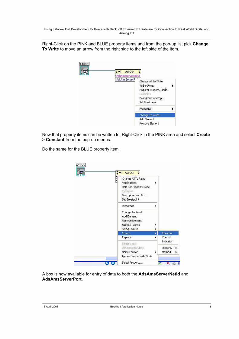
Right-Click on the PINK and BLUE property items and from the pop-up list pick Change
To Write to move an arrow from the right side to the left side of the item.
Now that property items can be written to, Right-Click in the PINK area and select Create
> Constant from the pop-up menus.
Do the same for the BLUE property item.
A box is now available for entry of data to both the AdsAmsServerNetId and
AdsAmsServerPort.
16 April 2008 Beckhoff Application Notes 9
Using Labview Full Development Software with Beckhoff Ethernet/IP Hardware for Connection to Real World Digital and
Analog I/O
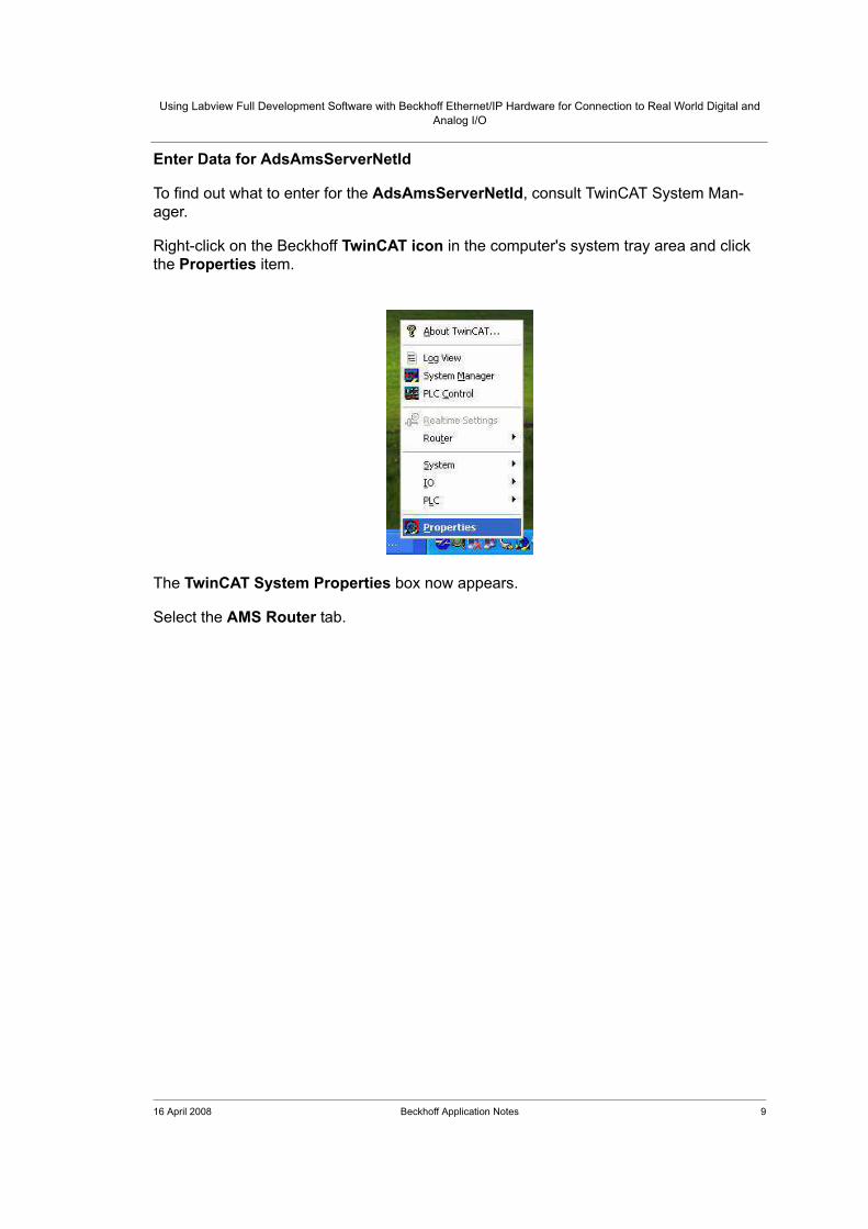
Enter Data for AdsAmsServerNetId
To find out what to enter for the AdsAmsServerNetId, consult TwinCAT System Man-
ager.
Right-click on the Beckhoff TwinCAT icon in the computer's system tray area and click
the Properties item.
The TwinCAT System Properties box now appears.
Select the AMS Router tab.

16 April 2008 Beckhoff Application Notes 10
Using Labview Full Development Software with Beckhoff Ethernet/IP Hardware for Connection to Real World Digital and
Analog I/O
For the Local Computer, copy the AMS Net Id: address out of this window and paste
this value in the PINK AdsAmsServerNetId box in the Labview diagram.
The Labview pointer must be changed to the data entry mode to do this. This is generally
accomplished in Labview by pressing the TAB key to cycle through the available tools the
pointer can be changed into.
Enter Data for AdsAmsServerPort
The Port number needs to be 301 to get the variables in the TwinCAT System Manager's
Additional Task. In the coming slides the location of this value will be pointed out.
Add a Flat Sequence Structure
The OCX control only needs to be referenced once for all the items to be exposed. Put a
Structure called a Flat Sequence around the code created so far in the Labview Diagram
to be sure this section can only happen once.
Right-click in an open area of the Labview diagram window to display the Functions pal-
let (if it is not already being displayed).

16 April 2008 Beckhoff Application Notes 11
Using Labview Full Development Software with Beckhoff Ethernet/IP Hardware for Connection to Real World Digital and
Analog I/O
Hover the mouse over the Structures item and a new pop-up window appears. From that
window select the Flat Sequence icon.
In the Diagram, rubber-band the Flat Sequence structure completely around the items
created in the diagram thus far.
The Labview connections diagram should now look like the picture below:
The numbers written to the AdsAmsServerNetId will be what is needed to access the
server on your computer, not necessarily the route numbers shown in the example.
Create a While Loop
Right-Click somewhere in an open area of the Labview diagram to see the Functions
pallet (if it is not already displayed).

16 April 2008 Beckhoff Application Notes 12
Using Labview Full Development Software with Beckhoff Ethernet/IP Hardware for Connection to Real World Digital and
Analog I/O
Hover the mouse over the Structures item and the Structures pallet appears. Left-click
on the While Loop icon. On the Labview diagram, rubber-band a fairly large area. More
Labview code will be added here in the steps that follow.
Change to the wiring tool by pressing the TAB key, and wire from the outputs of the
AdsOcx properties box to the edge of the While Loop structure.
A "tunnel" is created to pass the data from one structure to the other. The Blue-Green line
is the reference to the AdsOcx Control and the Pink line is what Labview calls a "cluster"
of data. A cluster is just an array that contains differing data types.
16 April 2008 Beckhoff Application Notes 13
Using Labview Full Development Software with Beckhoff Ethernet/IP Hardware for Connection to Real World Digital and
Analog I/O
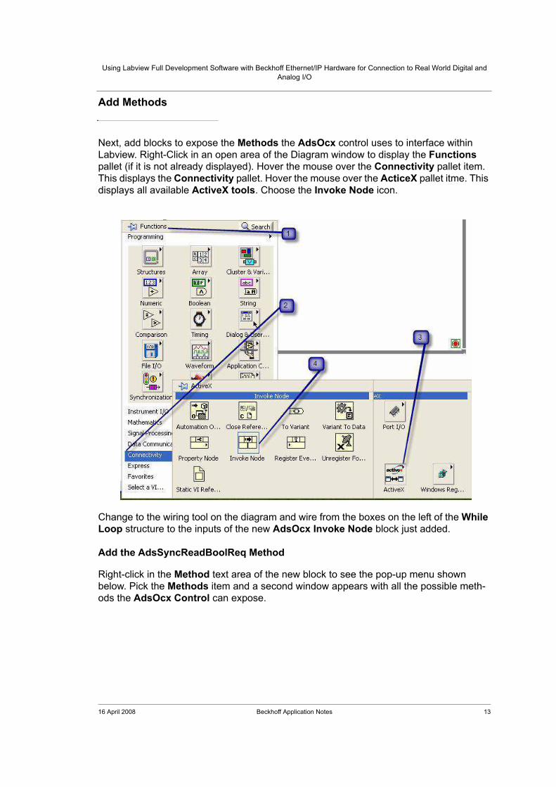
Add Methods
Next, add blocks to expose the Methods the AdsOcx control uses to interface within
Labview. Right-Click in an open area of the Diagram window to display the Functions
pallet (if it is not already displayed). Hover the mouse over the Connectivity pallet item.
This displays the Connectivity pallet. Hover the mouse over the ActiceX pallet itme. This
displays all available ActiveX tools. Choose the Invoke Node icon.
Change to the wiring tool on the diagram and wire from the boxes on the left of the While
Loop structure to the inputs of the new AdsOcx Invoke Node block just added.
Add the AdsSyncReadBoolReq Method
Right-click in the Method text area of the new block to see the pop-up menu shown
below. Pick the Methods item and a second window appears with all the possible meth-
ods the AdsOcx Control can expose.
16 April 2008 Beckhoff Application Notes 14
Using Labview Full Development Software with Beckhoff Ethernet/IP Hardware for Connection to Real World Digital and
Analog I/O
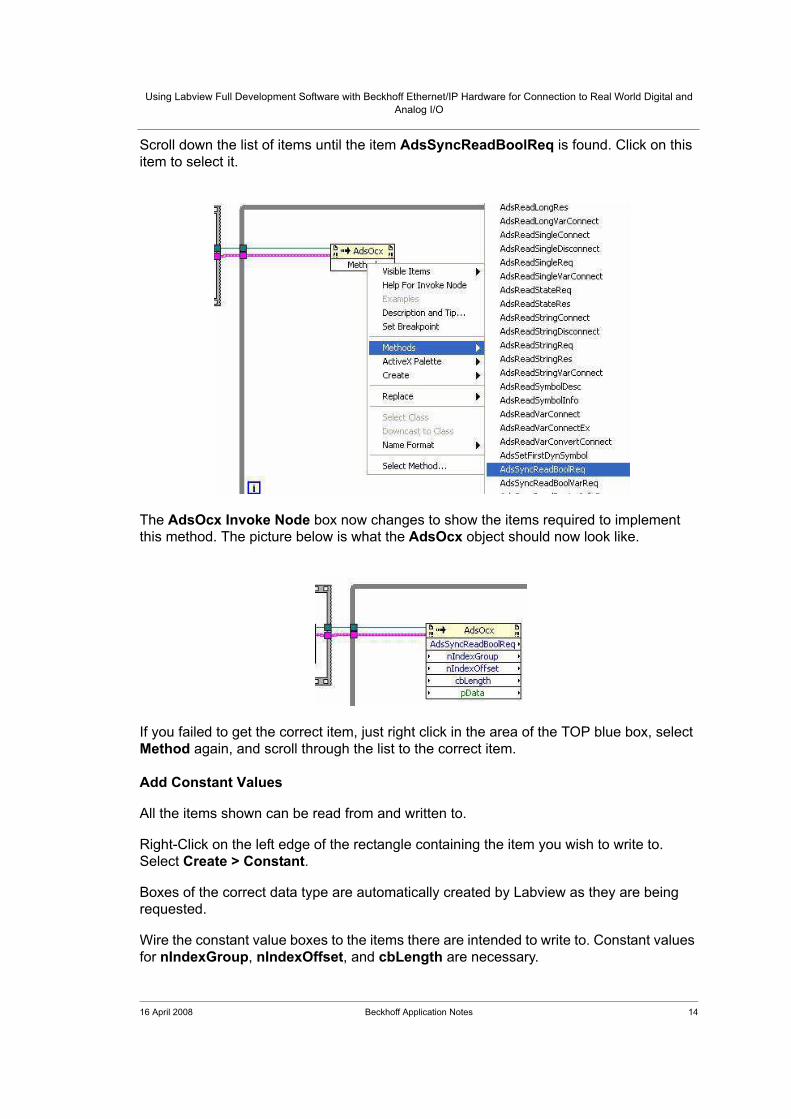
Scroll down the list of items until the item AdsSyncReadBoolReq is found. Click on this
item to select it.
The AdsOcx Invoke Node box now changes to show the items required to implement
this method. The picture below is what the AdsOcx object should now look like.
If you failed to get the correct item, just right click in the area of the TOP blue box, select
Method again, and scroll through the list to the correct item.
Add Constant Values
All the items shown can be read from and written to.
Right-Click on the left edge of the rectangle containing the item you wish to write to.
Select Create > Constant.
Boxes of the correct data type are automatically created by Labview as they are being
requested.
Wire the constant value boxes to the items there are intended to write to. Constant values
for nIndexGroup, nIndexOffset, and cbLength are necessary.
16 April 2008 Beckhoff Application Notes 15
Using Labview Full Development Software with Beckhoff Ethernet/IP Hardware for Connection to Real World Digital and
Analog I/O
Wire all three numeric constant boxes to their associated items in the AdsOcx Invoke
Node.
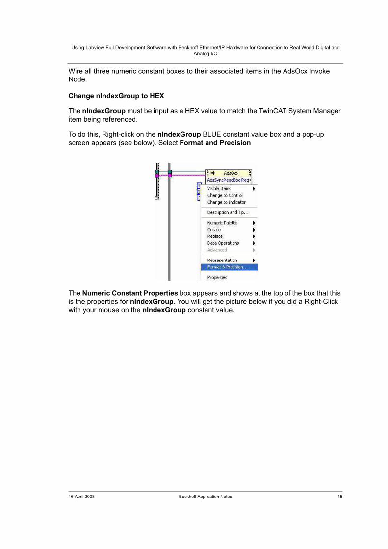
Change nIndexGroup to HEX
The nIndexGroup must be input as a HEX value to match the TwinCAT System Manager
item being referenced.
To do this, Right-click on the nIndexGroup BLUE constant value box and a pop-up
screen appears (see below). Select Format and Precision
The Numeric Constant Properties box appears and shows at the top of the box that this
is the properties for nIndexGroup. You will get the picture below if you did a Right-Click
with your mouse on the nIndexGroup constant value.

16 April 2008 Beckhoff Application Notes 16
Using Labview Full Development Software with Beckhoff Ethernet/IP Hardware for Connection to Real World Digital and
Analog I/O
Select Hexadecimal format and then press the OK button at the bottom of this pop-up
box to accept your selection. You will now be able to enter the data in the numeric con-
stant connected to the nIndexGroup item in HEX.
Right-Click on the TwinCAT icon in the computer's system tray and select the System
Manager. In the System Manager open the file for National Instruments Labview
Demo.tsm. Expand the Additional Tasks section, Task 1, and also expand the Inputs.
Have both the System Manager window and the Labview diagram window open at the
same time.

16 April 2008 Beckhoff Application Notes 17
Using Labview Full Development Software with Beckhoff Ethernet/IP Hardware for Connection to Real World Digital and
Analog I/O
Look in the TwinCAT System Manager at the Additional Task, Task 1, Inputs, item Din_1.
With Din_1 highlighted, the main window in the System Manager shows everything you'll
need to know about that variable when the "variable" TAB is being displayed. Everything
needed to enter into the Labview constant we have created is shown in the picture below:

16 April 2008 Beckhoff Application Notes 18
Using Labview Full Development Software with Beckhoff Ethernet/IP Hardware for Connection to Real World Digital and
Analog I/O
Display Digital Input in the Labview front Panel
Now we need to actually get the digital input and display it on the Labview front panel.
While still in the Labview diagram, Right-click on the right side of the green pData vari-
able, select Create, and then select Indicator.
Wire the new Labview indicator to the pData right-side connection point. Even though we
have everything we think we need to display the Boolean from TwinCAT in the Labview
application there is still a Labview error that needs to be corrected.
We need to make a Local Variable of the pData indicator we just created. Right-Click on
the pData indicator, select Create, and then select Local Variable.

16 April 2008 Beckhoff Application Notes 19
Using Labview Full Development Software with Beckhoff Ethernet/IP Hardware for Connection to Real World Digital and
Analog I/O
A rectangular box with the name of the indicator appears on the diagram.
Move the newly created local variable pData over to the left side of the AdsOcx Invoke
Node because we are going to wire this local variable into the left side of pData item in
the AdsOcx object.
If you tried to wire in the local variable right now it won't work because the local variable is
created in a mode to be written to.
To read the local variable we must Right-Click on the local variable and from the list of
items select Change To Read.
Once that has been completed we can now wire the local variable in the left side of pData
item in the AdsOcx object.
The Labview diagram should now lappear as shown below:
Save Progress
It's time to start saving your work. Notice the asterisk in the top left corner of the window.
Any time we have unsaved work in Labview, or TwinCAT for that matter, the asterisk
appears to show we have unsaved changes.

16 April 2008 Beckhoff Application Notes 20
Using Labview Full Development Software with Beckhoff Ethernet/IP Hardware for Connection to Real World Digital and
Analog I/O
Save your Labview project as Demo2. Labeview adds the ".vi" extension after your file
name when the file gets saved on your hard drive.
Complete While Loop
You will notice a small "i" at the bottom left corner of the While Loop in the Labview dia-
gram. Right-Click on the "i" and select Create, then Indicator. Rename the indicator "Iter-
ations". Every time the While Loop "loops" through the code inside the While Loop the "i"
counts up to show how many time the While Loop has executed.
We also need a way to exit the While Loop. The red stop sign at the bottom right corner of
the While Loop Structure is used to exit the While Loop structure. Right-click on the red
stop sign and select Create, then Control.


![Tutorial: LabVIEW MathScriptders.kilicaslan.nom.tr/doc/19/42/LabVIEW MathScript.pdf6 LabVIEW MathScript Tutorial: LabVIEW MathScript [End of Example] 3.2 HELP You may also type help](https://static.fdocuments.us/doc/165x107/5e9941194c6bb22c6123c750/tutorial-labview-mathscriptpdf-6-labview-mathscript-tutorial-labview-mathscript.jpg)