Using IPN60R3K4CE (CoolMOS CE in SOT-223 package) · VARISTOR 423 V 2.5 kA DISC 10MM 1 3 BR1 Micro...
19
Application Note 2.0 www.infineon.com/16w-led-driver-eval 10/14/2016 AN_201610_PL52_003 16 W single end cap T8 lighting demo board Using IPN60R3K4CE (CoolMOS ™ CE in SOT-223 package) About this document Scope and purpose This document is for a 16 W/270 mA single stage single end cap T8 LED lamp reference using average current control and a cascaded structure for a floating bulk topology design using the Infineon LED driver ICL8201 and CoolMOS™ IPN60R3K4CE (SOT-223). It has high efficiency, high PFC and various protection features with a very low external component count. The ICL8201 also supports a simple buck inductor without an auxiliary winding. Intended audience This document is intended for users of the ICL8201 who wish to design very low cost, high efficiency, high power factor LED drivers in a single end cap T8 form factor for LED lamps. It also showcases the use of CoolMOS™ CE in a SOT-223 package. Figure 1 ICL8201 demo board
Transcript of Using IPN60R3K4CE (CoolMOS CE in SOT-223 package) · VARISTOR 423 V 2.5 kA DISC 10MM 1 3 BR1 Micro...

Application Note 2.0
www.infineon.com/16w-led-driver-eval 10/14/2016
AN_201610_PL52_003
16 W single end cap T8 lighting demo boardUsing IPN60R3K4CE (CoolMOS™ CE in SOT-223 package)
About this document
Scope and purpose
This document is for a 16 W/270 mA single stage single end cap T8 LED lamp reference using average currentcontrol and a cascaded structure for a floating bulk topology design using the Infineon LED driver ICL8201 andCoolMOS™ IPN60R3K4CE (SOT-223). It has high efficiency, high PFC and various protection features with a verylow external component count. The ICL8201 also supports a simple buck inductor without an auxiliary winding.
Intended audience
This document is intended for users of the ICL8201 who wish to design very low cost, high efficiency, high powerfactor LED drivers in a single end cap T8 form factor for LED lamps. It also showcases the use of CoolMOS™ CE in aSOT-223 package.
Figure 1 ICL8201 demo board

A
16 W Single End Cap T8 lighting demo boardUsing IPN60R3K4CE (CoolMOS™ CE in SOT-223 package)
Board introduction
Table of Contents
About this document .............................................................................................................................................1
Table of Contents ..................................................................................................................................................2
1 Board introduction ............................................................................................................................3
2 Board specifications...........................................................................................................................4
3 Build information...............................................................................................................................5
3.1 Schematic ................................................................................................................................................5
3.2 Board layout ............................................................................................................................................5
3.3 Bill of materials........................................................................................................................................6
3.4 Inductor specification .............................................................................................................................7
4 Test results.........................................................................................................................................8
4.1 Connections and initial power-up ..........................................................................................................8
4.2 Startup .....................................................................................................................................................8
4.3 Switching waveform................................................................................................................................9
4.4 Output waveform ....................................................................................................................................9
4.5 Input waveform .....................................................................................................................................10
5 Protections.......................................................................................................................................11
5.1 Output short protection........................................................................................................................11
5.2 Open output protection ........................................................................................................................12
5.3 Short winding protection......................................................................................................................13
6 Test results.......................................................................................................................................14
7 Thermal performance ......................................................................................................................15
8 Conclusion .......................................................................................................................................16
9 References .......................................................................................................................................17
Revision History...................................................................................................................................................18
pplication Note 2 2.0
11/29/2016

Application Note 3 2.0
11/29/2016
16 W Single End Cap T8 lighting demo boardUsing IPN60R3K4CE (CoolMOS™ CE in SOT-223 package)
Board introduction
1 Board introduction
This application note is an engineering report for a single end cap T8 LED lamp reference design for high line input16 W/61 V converters. The converter uses the ICL8201, average current controlled, non-isolated single stage bucktopology in a cascade structure LED driver and the IPN60R3K4CE (SOT-223); a CE series of high voltage powerCoolMOS™. The distinguishing features of this reference design include high efficiency and high power factor witha single stage design, critical conduction mode operation with a single choke (without an auxiliary winding),regulated output current over a wide output voltage range, good EMI performance, and various modes ofprotection for high reliability with a small form factor that can easily fit into the single end cap of a standard T8LED lamp.
This document contains the list of features, the power supply specification, schematic, bill of materials, and thetransformer construction documentation. Typical operating characteristics such as performance curves andoscilloscope waveforms are shown at the end of the report.
Figure 2 16 W/61 V, single end cap T8 LED lamp demo board based on IPN60R3K4CE CoolMOS™ CE
The operation of the ICL8201 controller and its feature set are explained in detail in the application note – 18 W270 mA single stage floating buck LED (single end cap T8) converter with ICL8201 and IPS65R1K5CE available onthe Infineon website at:
http://www.infineon.com/dgdl/Infineon-ICL8201_T8+Tube+Reference+Design-RD-v01_00-EN.pdf?fileId=5546d4624d6fc3d5014dd2e6b4ab7958
The benefits of a SOT-223 CoolMOS™ CE device are explained in detail at
http://www.infineon.com/cms/en/product/power/power-mosfet/latest-packages/sot-223/channel.html?channel=5546d462525dbac40153141e97d0618f
The application note
http://www.infineon.com/dgdl/Infineon-ApplicationNote_High_Voltage+CoolMOS_in_SOT-223-AN-v01_00-EN.pdf?fileId=5546d46253e9fadc0153f07db9d44209
IPN60R3K4CE
ICL8201

Application Note 4 2.0
11/29/2016
16 W Single End Cap T8 lighting demo boardUsing IPN60R3K4CE (CoolMOS™ CE in SOT-223 package)
Board specifications
2 Board specifications
The inputs for the 16 W ICL8201_T8 board are Line (L) and Neutral (N); the operating AC input voltage range is170 Vac to 277 Vac. The outputs of the 16 W ICL8201_T8 are V+ and V-, which can supply 61 V at 270 mA to the LEDmodule.
The efficiency of the module is >90% while the power factor is over 0.95.
The default setting (used for all measurements in this document) is 61 V at 270 mA at the output for the SOT-223evaluation.
Attention: This is a non-isolated design and high voltage exists at the output! Using an isolation transformer isadvised while evaluating this demo board
Table 1 Design specifications
Parameter Specification
Input voltage 170 Vac to 277 Vac
Input frequency 50 Hz
Output voltage 55 V to 75 V, 61 V default
Output current 270 mA
Output power 16.5 W default, 18 W maximum
Power factor >0.95
THD <20 %
Efficiency >90 %

Application Note 5 2.0
11/29/2016
16 W Single End Cap T8 lighting demo boardUsing IPN60R3K4CE (CoolMOS™ CE in SOT-223 package)
Build information
3 Build information
3.1 Schematic
Figure 3 Board schematic
3.2 Board layout
Figure 4 Board layout top view (left) and bottom view (right)
C2
CS1
GND2
COMP3
VCC4
GND5
DRAIN6
ICL8201G
U1
23
1IPN60R3K4CEQ1
C3
0.7
5
R6 C6
C4
31
NC
2
D4
C5
12
D2
R4
R5
12
C7
1
23
4 +-
~
~
LMB6S-TP
BR1
U
RV
1
C1
R1
R2
R3
12
C8
F1
L
N
V+
V-
R7
R8
12
D6
R9
2
1
3
Q2R10
32
1 Q3
L1
2.2u
12
C9
R11
R12GND
GND
GND
GND
GND
15T1
GND
GND
GND
12
D5
12
D1
12
D7
For Lightning Surge
For Over voltage Protection Circuit

Application Note 6 2.0
11/29/2016
16 W Single End Cap T8 lighting demo boardUsing IPN60R3K4CE (CoolMOS™ CE in SOT-223 package)
Build information
3.3 Bill of materials
Table 2 Bill of materials
No. Designator Manufacturer Part Number Description Qty
1 F1 Littelfuse 0263003.MXLFUSE, PCB, 3 A, 250 V, VERY
FAST ACTING1
2 RV1 EPCOS B72210S0301K101VARISTOR 423 V 2.5 kA DISC
10MM1
3 BR1Micro
CommercialLMB6S-TP
BRIDGE RECTIFIER 1 A 600 V
LMBS-11
4 L1 Bourns RL875-222K-RCINDUCTOR, 2.2 mH, ±10%, 180
mA, DCR=6.25 Ω 1
5 D1 ON Semi MUR260GDIODE, RECTIFIER, 2 A, 600 V,
DO-151
6 D2,D5 ON Semi MMSZ5245BT1GDIODE ZENER 12 V 500 mW
SOD1232
7 D4 Infineon BAS 16 E6327DIODE SWITCH 80 V 0.25 A
SOT231
8 D6 ON Semi MMSZ5268BT1GDIODE, ZENER, 82 V, 500 mW,
SOD-1231
9 D7 MULTICOMP 1N4007GDIODE, STANDARD, 1 A, 1000 V,
DO411
10 C1 Kemet F861AP154M310LCAP FILM 0.15 uF 630 VDC
RADIAL (P=10mm)1
11 C2 Faratronic C222G154K40CAP FILM 0.15 uF 400 VDC 10%
RADIAL1
12 C3 Murata GRM188R71A225KE15DCAP CER 2.2 uF 10 V 10% X7R
06031
13 C4 Yageo CC0603KRX7R8BB103CAP CER 10 nF 25 V 10% X7R
06031
14 C5 Yageo CC1206JRNPOBBN220CAP CER 22 pF 500 V 5% NP0
12061
15 C6 Murata GRM21BR71E225KA73LCAP CER 2.2 uF 25 V 10% X7R
08051
16 C7, C8 RUBYCON 100ZLJ33M8X11.5CAP ALU 100 V, 47 uF, ±20%,
10,000hrs @ 1052
17 C9 Rubycon 400PX2R2MEFC8X11.5CAP, ALU ELEC, 2.2 uF, 400 V,
RAD1
18 R1, R2, R10 Yageo RC1206FR-071MLRES 1.00 MOHM 1/4 W 1% 1206
SMD3
19 R4, R5 KOA Spear RK73H2BTTD5103FRES 510 kOHM 1/4 W 1% 1206
SMD2
20 R6 Vishay RCWE1206R750FKEA RES 0.75 R OHM 1/2 W 1% 1206 1

Application Note 7 2.0
11/29/2016
16 W Single End Cap T8 lighting demo boardUsing IPN60R3K4CE (CoolMOS™ CE in SOT-223 package)
Build information
SMD
21 R8 Yageo RC0603FR-071KLRES 1 kOHM 1/10W 1% 0603
SMD1
22 R9 Yageo RC0603FR-0710KLRES 10 kOHM 1/10W 1% 0603
SMD1
23 R11 Yageo RC0805JR-07560KLRES 560 kOHM 1/8W 5% 0805
SMD1
24 R12 Yageo RC0603JR-074R7LRES 4.7 R OHM 1/10W 5% 0603
SMD1
25 T1 Wurth 750342737 EP13, 850 uH, ±10% 1
26 Q1 Infineon IPN60R3K4CE MOSFET, 600 V, 3K4Ω, SOT-223 1
27 Q2 NXP PBHV9050TTRANSISTOR PNP 500 V 150 mA
SOT231
28 Q3 Infineon SMBT3904TRANSISTOR NPN 40 V 150 mA
SOT231
29 U1 Infineon ICL8201 LED buck controller 1
30 Ferrite Bead KEMET B-20F-38FERRITE CORE, CYLINDRICAL,
1.5mm X 4.3mm1
31 PCBFR4, 2 Layer, 1oz, Soldermask,
42x20x15 mm1
3.4 Inductor specification
Figure 5 Inductor specification

Application Note 8 2.0
11/29/2016
16 W Single End Cap T8 lighting demo boardUsing IPN60R3K4CE (CoolMOS™ CE in SOT-223 package)
Test results
4 Test results
4.1 Connections and initial power-up
Figure 6 PCB bottom showing where to connect AC input and load.
Connect the AC input to the board as shown above. The output voltage (V+) and ground (GND) should beconnected to an external load at the terminals. In order to load with an external resistor for testing, use a 220 Ω resistor to obtain 18 W or 275 mA at 60 V.
4.2 Startup
When the AC input voltage is applied to the reference board, the Vcc capacitor will be charged through external
LED module, buck choke (T1), external power switch (Q1) and Vcc diode. Once the Vcc voltage reaches 7.5 V, the IC
will start switching with a digital soft start and enter into normal operation.
C1: (Yellow) Bulk voltage (Vbulk)
C2: (Red) Supply voltage (Vcc)
C3: (Blue) LED module voltage (VLED)C4: (Green) LED module current (ILED)
Figure 7 Startup waveform
AC input:
Line
AC input:
Neutral
Output:
V+
Output: GND

Application Note 9 2.0
11/29/2016
16 W Single End Cap T8 lighting demo boardUsing IPN60R3K4CE (CoolMOS™ CE in SOT-223 package)
Test results
4.3 Switching waveform
The current mode controller (ICL8201) has zero current switching without a zero crossing detection winding, bysensing the drain pin voltage of the controller. This helps to simplify the structure of the buck choke by notrequiring an auxiliary winding and improving both EMI performance and efficiency. A typical switching waveformof the ICL8201 is shown below.
C1: (Yellow) Gate voltage of the high-side MOSFET (Vgate-high)C2: (Red) Current sense voltage (Vcs)C3: (Blue) Drain to source voltage of high-side MOSFET (Vds-high)C4: (Green) Drain voltage of low-side MOSFET (Vd-low)
Figure 8 Switching waveform @277 Vac
4.4 Output waveform
The output capacitor is sized for an output current ripple that exhibits no visible light modulation. The following
figure shows the measured waveform of output voltage and current during normal operation at 230 Vac and fullload.
C3: (Blue) LED module voltage (VLED)C4: (Green) LED module current (ILED)
Figure 9 Startup waveform
Application Note 10 2.0
11/29/2016
16 W Single End Cap T8 lighting demo boardUsing IPN60R3K4CE (CoolMOS™ CE in SOT-223 package)
Test results
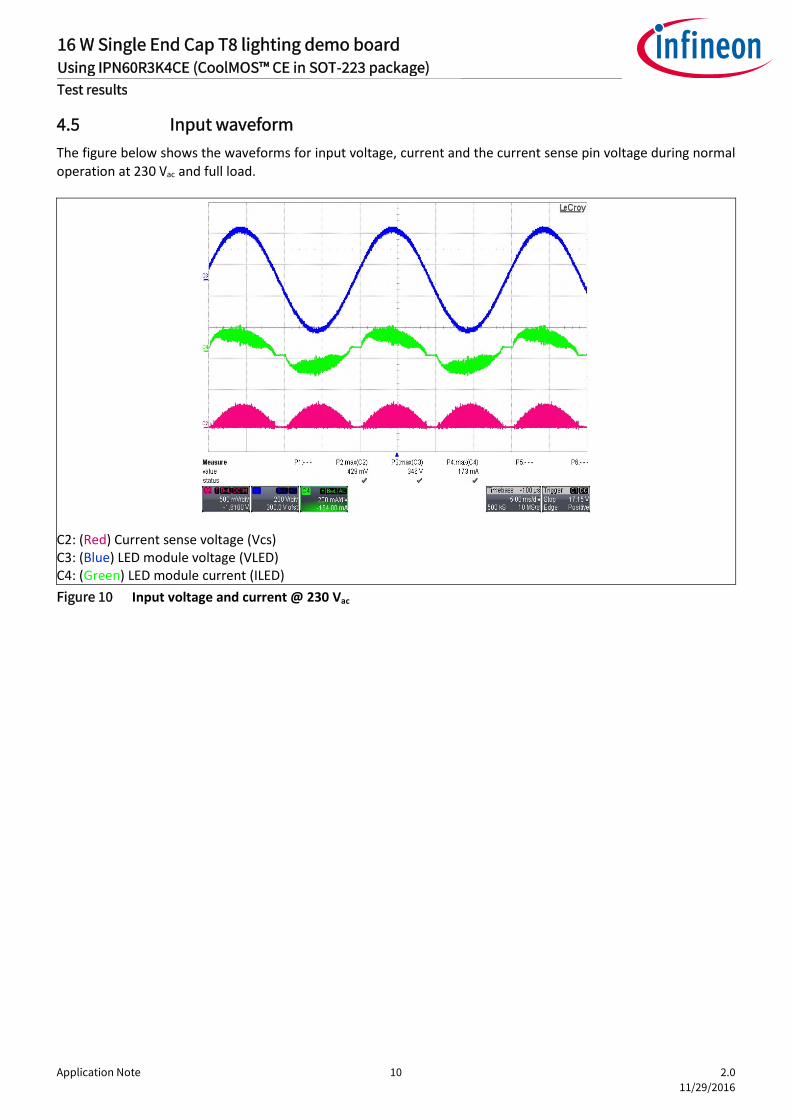
4.5 Input waveform
The figure below shows the waveforms for input voltage, current and the current sense pin voltage during normal
operation at 230 Vac and full load.
C2: (Red) Current sense voltage (Vcs)C3: (Blue) LED module voltage (VLED)C4: (Green) LED module current (ILED)
Figure 10 Input voltage and current @ 230 Vac

Application Note 11 2.0
11/29/2016
16 W Single End Cap T8 lighting demo boardUsing IPN60R3K4CE (CoolMOS™ CE in SOT-223 package)
Protections
5 Protections
5.1 Output short protection
The tested waveform in startup mode and run Mode is shown below. The system board enters into latch mode,
and the power consumption is 0.22 W @ Vin = 230 Vac/50 Hz.
C1: (Yellow) Vcc voltage
C2: (Red) High side MOSFET drain voltageC3: (Blue) LED module voltage (VLED)
C4: (Green) LED module current (ILED)
Figure 11 Waveform during start-up mode (61 V, 270 mA LED load @ Vin = 230 Vac/50 Hz)
C1: (Yellow) Vcc voltage
C2: (Red) High side MOSFET drain voltage
C3: (Blue) LED module voltage (VLED)
C4: (Green) LED module current (ILED)
Figure 12 Waveform during run mode (61 V, 270 mA LED load @ Vin = 230 Vac/50 Hz

Application Note 12 2.0
11/29/2016
16 W Single End Cap T8 lighting demo boardUsing IPN60R3K4CE (CoolMOS™ CE in SOT-223 package)
Protections
5.2 Open output protection
Adding an external OVP circuit allows this reference design to achieve output open circuit protection. The testedwaveform during start-up mode and run mode is shown below. When the system enters into auto restart mode,
the power consumption is 0.3 W and Vled is clamped to 82 V @ Vin = 230 Vac/50 Hz.
C1: (Yellow) Vcc voltage
C2: (Red) High side MOSFET drain voltageC3: (Blue) LED module voltage (VLED)
C4: (Green) LED module current (ILED)
Figure 13 Waveform of start-up mode (61 V, 270 mA LED load @ Vin = 230 Vac/50 Hz)
C1: (Yellow) Vcc voltage
C2: (Red) High side MOSFET drain voltageC3: (Blue) LED module voltage (VLED)
C4: (Green) LED module current (ILED)
Figure 14 Waveform of run mode (61 V, 270 mA LED load @ Vin = 230 Vac/50 Hz)

Application Note 13 2.0
11/29/2016
16 W Single End Cap T8 lighting demo boardUsing IPN60R3K4CE (CoolMOS™ CE in SOT-223 package)
Protections
5.3 Short winding protection
The figures below show the waveforms of Vcc, the LED output current, and the drain on the high side MOSFET
during the short winding protection under start-up and run mode.
C1: (Yellow) Vcc voltage
C2: (Red) High side MOSFET drain voltage (VDrain_H)
C4: (Green) LED module current (ILED)
Figure 15 Waveform of start-up mode (61 V, 270 mA LED load @ Vin = 230 Vac/50 Hz)
C1: (Yellow) Vcc voltage
C2: (Red) High side MOSFET drain voltage(VDrain_H)C4: (Green) LED module current (ILED)
Figure 16 Waveform of run mode (61 V, 270 mA LED load @ Vin = 230 Vac/50 Hz)

Application Note 14 2.0
11/29/2016
16 W Single End Cap T8 lighting demo boardUsing IPN60R3K4CE (CoolMOS™ CE in SOT-223 package)
Test results
6 Test results
Table 3 Efficiency results at 61 V and 270 mA of LED load
Vin@50 Hz
(Vac)
Pin
(W)
PF THD Vout
(VDC)
Iout
(mA)
Pout
(W)
ΔIout
(%)
Efficiency
(%)
Average
Efficiency (%)
170 18.04 0.99 12.4 60.4 273 16.49 +1.11 91.40
90.94%
200 18.12 0.98 12.3 60.4 274 16.55 +1.48 91.34
230 18.19 0.97 13.1 60.4 274 16.55 +1.48 90.98
265 18.33 0.95 14.4 60.4 275 16.61 +1.85 90.61
277 18.38 0.95 14.8 60.4 275 16.61 +1.85 90.36
Figure 17 Demo Board Efficiency Results

Application Note 15
16 W Single End Cap T8 lighting demo boardUsing IPN60R3K4CE (CoolMOS™ CE in SOT-223 package)
Thermal performance
7 Thermal performanceThe table below shows the thermal performance of the IC and power MOSFET after running for >30 minuteswithout an enclosure in a 25°C ambient temperature (two different conditions shown below).
Figure 18 Thermal images of the top of the board (left) and botto
Condition A: Input voltage = 170 Vac - 277 Vac, Pout = 16.2 W (59.6 V/27
Table 4 Thermal performance at 59.6 V output voltage
Item 170 Vac 230 Vac 277 Va
Q1 65.0 69.2 74.5
U1 56.0 56.4 58.9
BR1 51.8 49.2 49.9
L1 47.6 44.2 44.3
Ambient T 26.8 27.8 28.2
Condition B: Input voltage = 170 Vac - 277 Vac, Pout = 18.3 W (67.4 V/2
Table 5 Thermal performance at 67.4 V output voltage
Item 170 Vac 230 Vac 277 Va
Q1 68.6 72.2 77.6
U1 59.6 61.2 64.0
BR1 55.6 49.2 55.7
L1 50.8 49.3 50.0
Ambient T 28.0 27.4 27.4
L1
2.0
11/29/2016
m of the board (right).
2 mA)
c
72 mA)
c
Q1

Application Note 16 2.0
11/29/2016
16 W Single End Cap T8 lighting demo boardUsing IPN60R3K4CE (CoolMOS™ CE in SOT-223 package)
Conclusion
8 ConclusionThe board effectively shows the performance of the IPN60R3K4CE – CoolMOS™ CE in the SOT-223 package forlighting applications. Furthermore the SOT-223 package gives the opportunity to further lower the cost of thesystem in comparison to the usage of DPAK package while not sacrificing pin-to-pin compatability.
PCB area savings and package height reductions give extra value, especially for lighting customers who haveincreased power density requirements.
An additional benefit of the Infineon SOT-223 package is the increased creepage distance between Gate andSource pins when compared to DPAK packages due to removing the middle drain pin.
These benefits for lighting applications make CoolMOS™ CE in the SOT-223 package an ideal fit for low cost lowpower lighting applications.

Application Note 17 2.0
11/29/2016
16 W Single End Cap T8 lighting demo boardUsing IPN60R3K4CE (CoolMOS™ CE in SOT-223 package)
References
9 References
[1] 18 W 270 mA single stage floating buck LED (Single End Cap T8) converter with ICL8201 & IPS65R1K5CEavailable on Infineon website at
http://www.infineon.com/dgdl/Infineon-ICL8201_T8+Tube+Reference+Design-RD-v01_00-EN.pdf?fileId=5546d4624d6fc3d5014dd2e6b4ab7958
[2] The benefits of SOT-223 CoolMOS™ CE device is explained in detail at
http://www.infineon.com/cms/en/product/power/power-mosfet/latest-packages/sot-223/channel.html?channel=5546d462525dbac40153141e97d0618f
[3] CoolMOS™ in SOT-223
http://www.infineon.com/dgdl/Infineon ApplicationNote_High_Voltage+CoolMOS_in_SOT-223-AN-v01_00EN.pdf?fileId=5546d46253e9fadc0153f07db9d44209

Application Note 18 2.0
11/29/2016
16 W Single End Cap T8 lighting demo boardUsing IPN60R3K4CE (CoolMOS™ CE in SOT-223 package)
Revision History
Revision History
Major changes since the last revision
Page or Reference Description of change

Trademarks of Infineon Technologies AGµHVIC™, µIPM™, µPFC™, AU-ConvertIR™, AURIX™, C166™, CanPAK™, CIPOS™, CIPURSE™, CoolDP™, CoolGaN™, COOLiR™, CoolMOS™, CoolSET™, CoolSiC™,DAVE™, DI-POL™, DirectFET™, DrBlade™, EasyPIM™, EconoBRIDGE™, EconoDUAL™, EconoPACK™, EconoPIM™, EiceDRIVER™, eupec™, FCOS™, GaNpowIR™,HEXFET™, HITFET™, HybridPACK™, iMOTION™, IRAM™, ISOFACE™, IsoPACK™, LEDrivIR™, LITIX™, MIPAQ™, ModSTACK™, my-d™, NovalithIC™, OPTIGA™,OptiMOS™, ORIGA™, PowIRaudio™, PowIRStage™, PrimePACK™, PrimeSTACK™, PROFET™, PRO-SIL™, RASIC™, REAL3™, SmartLEWIS™, SOLID FLASH™,SPOC™, StrongIRFET™, SupIRBuck™, TEMPFET™, TRENCHSTOP™, TriCore™, UHVIC™, XHP™, XMC™
Trademarks updated November 2015
Other TrademarksAll referenced product or service names and trademarks are the property of their respective owners.
Edition 2016-10-03
AppNote Number
Published by
Infineon Technologies AG
81726 Munich, Germany
© 2016 Infineon Technologies AG.
All Rights Reserved.
Do you have a question about thisdocument?
Email: [email protected]
Document reference
IMPORTANT NOTICEThe information contained in this application noteis given as a hint for the implementation of theproduct only and shall in no event be regarded as adescription or warranty of a certain functionality,condition or quality of the product. Beforeimplementation of the product, the recipient of thisapplication note must verify any function and othertechnical information given herein in the realapplication. Infineon Technologies herebydisclaims any and all warranties and liabilities ofany kind (including without limitation warranties ofnon-infringement of intellectual property rights ofany third party) with respect to any and allinformation given in this application note.
The data contained in this document is exclusivelyintended for technically trained staff. It is theresponsibility of customer’s technical departmentsto evaluate the suitability of the product for theintended application and the completeness of theproduct information given in this document withrespect to such application.
For further information on the product, technology,delivery terms and conditions and prices pleasecontact your nearest Infineon Technologies office(www.infineon.com).
WARNINGSDue to technical requirements products maycontain dangerous substances. For information onthe types in question please contact your nearestInfineon Technologies office.
Except as otherwise explicitly approved by InfineonTechnologies in a written document signed byauthorized representatives of InfineonTechnologies, Infineon Technologies’ products maynot be used in any applications where a failure ofthe product or any consequences of the use thereofcan reasonably be expected to result in personalinjury.