Using Inertial Measurement Units to Calculate Knee Flexion ...
9
1. 2. 3. Using Inertial Measurement Units to Calculate Knee Flexion Angle Melissa Boswell Hannah O'Day Project Video Description Inertial Measurement Unit (IMU) sensors are electronic devices that measure and report a body's specific force, angular rate, and sometimes the magnetic field surrounding the body, using a combination of accelerometers, gyroscopes and magnetometers. Most people interact with these devices daily, via the ecent advances in wearable IMU technology, however, are allowing users to IMU in their smartphone that allows them accurate navigating ability. R capture and store hours of kinematic data. Traditionally, kinematic data was only attainable in motion capture laboratories equipped with multiple cameras that tracked a subject's motion via reflective markers worn on the body. With wearable, wireless IMU sensors, we have a unique opportunity - the ability to capture human motion in "natural" settings (outside of the laboratory) lasting multiple hours. One such IMU company, , uses a 3D accelerometer, Xsens 3D gyroscope, and 3D magnetometer in each of their IMU sensors to capture full 6 degree-of-freedom tracking of body segments. In this study, we started with a simple application using two Xsens IMUs to measure knee angle. Our experiment calculated the knee angle as a person is sitting in a chair with their initial knee flexion angle at 0 degrees (full extension) and flexing to 90 degrees at frequencies similar to that of walking and running. The knee flexion angle is calculated with measurements from IMUs attached to the shank and thigh. Using 2D video, markers and a goniometer, the subject's leg motion was be measured with video analysis to obtain a "ground truth" knee angle measurement. This was compared to the knee angle determined from the IMU sensor data combined with the Xsens biomechanical model, output as a data file of joint angles over time. The knee joint angles was then input into OpenSim to observe the motion. In addition to directly outputting the joint angles, each individual IMU sensor's orientation was output prior to feedback from the Xsens biomechanical model. These orientations, output as quaternions, were transformed into rotation matrices and input into an OpenSim Inverse Kinematics (IK) script. IK in OpenSim determined the positions that best matched the input rotation matrices at each time step, and the resulting knee angle was observed. Once model kinematics were successfully reconstructed in OpenSim, we validated the determined knee joint angle from both the Xsens biomechanical model and using IK in OpenSim with our ground truth motion capture data. The goal of this project was to determine if knee angle could be measured accurately with the IMU sensors. The motivation for this goal is that if validated, the IMUs can be used for more complex movements, such as gait, to characterize kinematics without the restrictions of a motion capture system. Many questions can be addressed with the ability to analyze kinematics in a natural setting and for long periods of time. Research Questions Can knee joint angle be calculated accurately with two IMU's? Can the IMU data be input into OpenSim to reconstruct movement kinematics? Can kinematics be reconstructed in OpenSim with IMU measurements in real-time? Project Overview I. Pipeline for Processing IMU Data II. Knee flexion experiment (IMU and 2D video marker tracking) III. Reconstructing motion in OpenSim using Xsens-estimated knee joint angle IV. Reconstructing motion in OpenSim from Inverse Kinematics using Xsens IMU orientation data I. Pipeline for Processing IMU Data: How to go from real world motion to model segment kinematics
Transcript of Using Inertial Measurement Units to Calculate Knee Flexion ...

1. 2. 3.
Using Inertial Measurement Units to Calculate Knee Flexion Angle
Melissa BoswellHannah O'Day
Project Video
Description
Inertial Measurement Unit (IMU) sensors are electronic devices that measure and report a body's specific force, angular rate, and sometimes the magnetic field surrounding the body, using a combination of accelerometers, gyroscopes and magnetometers. Most people interact with these devices daily, via the
ecent advances in wearable IMU technology, however, are allowing users to IMU in their smartphone that allows them accurate navigating ability. Rcapture and store hours of kinematic data. Traditionally, kinematic data was only attainable in motion capture laboratories equipped with multiple cameras that tracked a subject's motion via reflective markers worn on the body. With wearable, wireless IMU sensors, we have a unique opportunity - the ability to capture human motion in "natural" settings (outside of the laboratory) lasting multiple hours. One such IMU company, , uses a 3D accelerometer, Xsens3D gyroscope, and 3D magnetometer in each of their IMU sensors to capture full 6 degree-of-freedom tracking of body segments.
In this study, we started with a simple application using two Xsens IMUs to measure knee angle. Our experiment calculated the knee angle as a person is sitting in a chair with their initial knee flexion angle at 0 degrees (full extension) and flexing to 90 degrees at frequencies similar to that of walking and running. The knee flexion angle is calculated with measurements from IMUs attached to the shank and thigh. Using 2D video, markers and a goniometer, the subject's leg motion was be measured with video analysis to obtain a "ground truth" knee angle measurement. This was compared to the knee angle determined from the IMU sensor data combined with the Xsens biomechanical model, output as a data file of joint angles over time. The knee joint angles was then input into OpenSim to observe the motion. In addition to directly outputting the joint angles, each individual IMU sensor's orientation was output prior to feedback from the Xsens biomechanical model. These orientations, output as quaternions, were transformed into rotation matrices and input into an OpenSim Inverse Kinematics (IK) script. IK in OpenSim determined the positions that best matched the input rotation matrices at each time step, and the resulting knee angle was observed. Once model kinematics were successfully reconstructed in OpenSim, we validated the determined knee joint angle from both the Xsens biomechanical model and using IK in OpenSim with our ground truth motion capture data.
The goal of this project was to determine if knee angle could be measured accurately with the IMU sensors. The motivation for this goal is that if validated, the IMUs can be used for more complex movements, such as gait, to characterize kinematics without the restrictions of a motion capture system. Many questions can be addressed with the ability to analyze kinematics in a natural setting and for long periods of time.
Research Questions
Can knee joint angle be calculated accurately with two IMU's?Can the IMU data be input into OpenSim to reconstruct movement kinematics?Can kinematics be reconstructed in OpenSim with IMU measurements in real-time?
Project Overview
I. Pipeline for Processing IMU Data
II. Knee flexion experiment (IMU and 2D video marker tracking)
III. Reconstructing motion in OpenSim using Xsens-estimated knee joint angle
IV. Reconstructing motion in OpenSim from Inverse Kinematics using Xsens IMU orientation data
I. Pipeline for Processing IMU Data: How to go from real world motion to model segment kinematics

In the pipeline for processing IMU data, the IMU sensors are used first to obtain linear acceleration (from the accelerometer), angular velocity (from the gyroscope), and magnetometer readings of the desired motion or activity. The IMU sensors we used were sampling at 60 Hz and were small and lightweight Xsens (47x30x13 mm, 16 g). developed a sensor fusion algorithm, a Kalman filter called , such that orientation and position of the IMU sensors can be accurately estimated. XKF-3
Following the lower pathway, you see that Xsens estimates kinematics using a combination of orientation and position data from the IMUs their biomechanical model andwhich incorporates joint characteristics and external contacts. In this way, they can update joint uncertainties and feedback updated orientation and position information to the sensor fusion algorithms. Xsens then outputs these estimated model kinematics, including the joint angles of the model at each time step. In our study, we were specifically looking at knee joint angle, so we extracted the Xsens-estimated knee rotation about the X,Y,Z axes.
We also worked through the upper pathway, using sensor orientation from the Xsens processing (prior to feedback with the biomechanical model) to estimate joint angles. This orientation data, output as quaternions, was translated into rotation matrices and input into an OpenSim IK C++ script that output various model kinematics. We specifically looked at the knee joint angle and used the (see below for a comparison of the Xsens vs. OpenSim knee model).gait10dof18musc OpenSim model
Comparing biomechanical models: Xsens vs. OpenSim Knee Model
Xsens Knee Model [1] OpenSim Knee Model [2]
"Soft Hinge"Allows for rotation in all planesbut sagittal plan more statistically likely
Single degree-of-freedomFemoral, tibial, patellar transformationsfunctions of knee angle
1. 2. 3. 4. 5.
6. 7. 8. 9.
10.
11.
12.
II. Knee Flexion Experiment
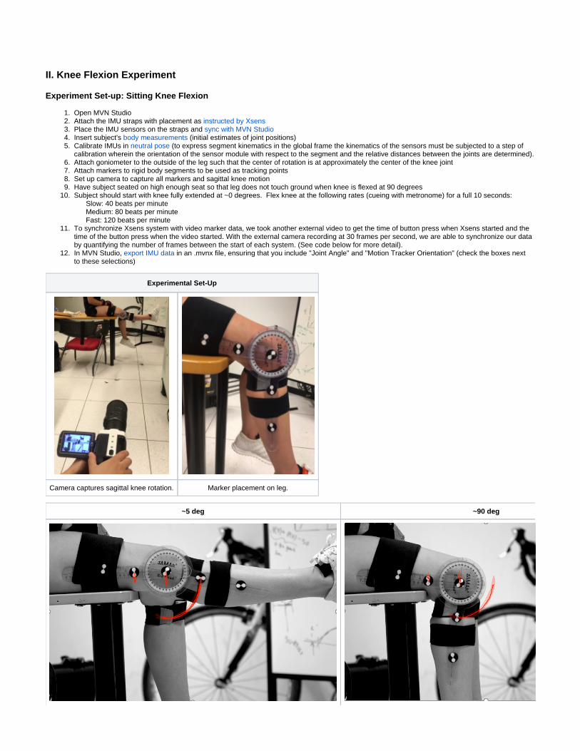
Experiment Set-up: Sitting Knee Flexion
Open MVN StudioAttach the IMU straps with placement as instructed by XsensPlace the IMU sensors on the straps and sync with MVN StudioInsert subject's (initial estimates of joint positions)body measurementsCalibrate IMUs in (to express segment kinematics in the global frame the kinematics of the sensors must be subjected to a step of neutral posecalibration wherein the orientation of the sensor module with respect to the segment and the relative distances between the joints are determined).Attach goniometer to the outside of the leg such that the center of rotation is at approximately the center of the knee jointAttach markers to rigid body segments to be used as tracking points Set up camera to capture all markers and sagittal knee motionHave subject seated on high enough seat so that leg does not touch ground when knee is flexed at 90 degreesSubject should start with knee fully extended at ~0 degrees. Flex knee at the following rates (cueing with metronome) for a full 10 seconds: Slow: 40 beats per minute Medium: 80 beats per minute Fast: 120 beats per minuteTo synchronize Xsens system with video marker data, we took another external video to get the time of button press when Xsens started and the time of the button press when the video started. With the external camera recording at 30 frames per second, we are able to synchronize our data by quantifying the number of frames between the start of each system. (See code below for more detail).In MVN Studio, in an .mvnx file, ensuring that you include "Joint Angle" and "Motion Tracker Orientation" (check the boxes next export IMU datato these selections)
Experimental Set-Up
Camera captures sagittal knee rotation. Marker placement on leg.
~5 deg ~90 deg

1. 2.
a. 3.
a.
4.
a.
2D video screen captures of the marker tracking for the subject's leg at knee angle in the fully extended position (~5 deg) versus fully flexed (~90 deg).
III. Reconstructing motion in OpenSim using Xsens-estimated knee joint angle
Instructions for creating an from XSens .mnvx file in Matlab (See )OpenSim motion file README_JointAngles.txt
1. Run read_jointAngles_lowerbody_write_motion_file.m (Matlab)
a. This runs main_mvnx.m (this is code modified from Xsens Toolkit, Xsens North America Inc.)
This file loads two figures of the “first segment position” - the pelvis rotation in 3D and the pelvis 3D translation
i. main_mvnx.m uses the load_mvnx.m function (Xsens Toolkit)
ii. Outputs a data tree with all the biomechanical model segment and IMU sensor data (joint angles, joint velocities, joint accelerations etc.)
b. Creates a table of all joints and joint angles from IMU data at every time point (jointTable)
c. Outputs selected joint angles to a matrix with time as first row (allAnglesMatrix)
d. Creates motion file named “mvnxfilename_Xsens_jointangle_q.mot” of joint angles to input in Open Sim from Xsens IMU Data
This file has required OpenSim headings and formats data correctly for use with OpenSim model (but only has pelvis_tilt pelvis_tx pelvis_ty hip_flexion_r knee_angle_r ankle_angle_r)
2. Open your .osim model in OpenSim (the .osim models we have included correspond to each .mvnx file, and all start in the default position determined by the subject’s physical body position at the beginning of the experiment).
For example, if you used the LegSwing_40bpm_5-26-17.mvnx then you should load the gait10dof18musc_40.osim model
3. Input created .mot file into OpenSim through 'File -> Load Motion' and pick the mvnxfilename_Xsens_jointangle_q.mot file.
~5 deg ~90 deg
Examples of the reconstructed seated knee flexion motion in the OpenSim model.
IV. Reconstructing motion in OpenSim from Inverse Kinematics using Xsens IMU orientation data (see )README_OpenSIMIK.txt
Output IMU orientation data as quaternions in .mvnx file (default setting for Xsens Awinda sensors using MVN Studio)Run rotationMatricesForOsimIK.m
This code transforms quaternions from .mvnx file into a rotation matrixThe model used in this code must have the initial conditions to that of the experimental set-up
This can be done by opening the OpenSim model ( ), and setting the initial condition of the joints to that of the gait10dof18musc.osimsubject at time = 0, and saving the pose as the "Default Pose". This has been done in the following files for the 40, 80 and 120 BPM trials respectively: , , gait10dof18musc_40.osim gait10dof18musc_80.osim gait10dof18musc_120.osim
Build and run , (you'll need to add these to your directory where the C++ code is saved , futureOrientationInverseKinematics.cpp CMakeLists.txt fut)ureOrientationInverseKinematics.trc
This code takes the determined rotation matrices and applies them to each respective segment

4.
5.
The code then runs an inverse kinematic simulation and outputs OpenSim kinematics files:futureOrientationInverseKinematics_Kinematics_q.sto
futureOrientationInverseKinematics_Kinematics_u.sto
futureOrientationInverseKinematics_Kinematics_dudt.sto
It is helpful to rename these based on the trial you are analyzing e.g. futureOrientationInverseKinematics_Kinematics_q_40.stoLoad the motion, the OpenSim joint angles file (e.g. to observe the reconstructed futureOrientationInverseKinematics_Kinematics_q_40.sto)motion and plot the knee joint angle in OpenSim.
Results
40 BPM (Walking)
Xsens
OpenSim

Root mean square error (RMSE) between Xsens joint angle and ground truth (2D video marker tracking) and OpenSim IK joint angle and ground truth (2D video marker tracking):
RMSE (deg) 40 BPM 80 BPM 120 BPM
Xsens* 4.1020 3.0574 3.792
OpenSim* 7.3835 8.6850 5.4153
*Compare with literature RMSE of 5.09 deg for knee flexion using Xsens sensors while walking (Zhang et al. 2013)
Comparing Xsens vs. OpenSim Inverse Kinematics joint estimates
In the above plots, the knee angle estimation that utilized Xsens IMU sensor orientations in combination with ,OpenSim Inverse Kinematics is shown in bluethe knee angle estimation from the , and the ground truth knee angle determined from Xsens biomechanical model is shown in dark orange 2D video
marker tracking is shown in yellow.
In each plot, we see that the Xsens estimate is closer to the knee angle than the estimate. This is also reflected in the root mean ground truth OpenSim_IKsquare error values for each deg and 7.16 method: averaged across all three speeds, Xsens and had an RMSE of 3.65OpenSim IK deg, respectively. These RMSEs are comparable with literature values of Xsens IMU sensor validation with camera-based motion capture, where they saw RMSE's of 5.09 degrees for knee flexion during walking [4].
The Xsens system is unique in its approach to estimate body segment orientation and position changes with a combination of the integrated inertial data as well as continuous update using a biomechanical model of the human body. By facilitating the constraints of the model, notably that the segments are connected by joints, the kinematics of body segments are corrected for drift and other errors.
We think that Xsens has a better knee angle estimate because of their sensor fusion scheme with both a prediction and correction step. In the prediction step (pictured on left below), they integrate acceleration and angular velocities on all sensors. This is followed by prediction of segment kinematics using a known sensor to body alignment and a 23 segment biomechanical model of the body. However, skin and soft tissue artifacts influence the IMU measurements, much like traditional reflective marker systems due to contracting muscles and skin/fat motion [1]. In the correction and joint measurement update step (right), these artifacts are reduced by using the knowledge that the two segments are on average connected but with a statistical uncertainty. Detecting contact points of the body with the external world limit the boundless integration error of the assembled body model in the global frame and constrains the global position and velocity. For example, if a person is sitting but moving around (e.g. on a bike), then you could include a constraint that the pelvis is fixed. After the correction step, these updated kinematics are fed back to the sensor fusion algorithms and segment kinematic step to be used in the next time frame [1].

Xsens used a scaled model based on the subject's body measurements; however, our OpenSim model was not scaled. Thus, we were not able to incorporate position data and the Inverse Kinematics simulation was only based on orientation data, which makes the joint estimation less accurate. Moreover, with only orientation driven motion "capture", it is not possible to analyze the clearance of both feet (such as in running or jumping) or determine displacement of body with respect to a coordinate system not fixed to the body. Therefore, in the future we want to do real-time estimation of body segment orientation and position changes using raw IMU data and an Opensim model, which we can scale based on the subject's body measurements.
Why Xsens joint estimation is not perfect
There are a number of reasons why the Xsens joint estimation is not equal to the ground truth knee angles. As mentioned in the experimental set-up, the subject must stand in a neutral pose, so that the rotation from sensor to body segment can be determined by matching the orientation of the sensor in the global frame with the known orientation of each segment in this pose. However, if the subject's sensors are placed incorrectly, (e.g. the thigh sensor is put on horizontally instead of vertically) or even shifted slightly, then the model will be expecting the sensor to be placed one way and will calibrate based on this incorrect conformation. Thus, the resulting joint angles will have slight errors. In a similar manner, if the subject does not assume the correct neutral pose, the sensors will be calibrated incorrectly and there will be error incurred. In addition, if there are magnetic disturbances, the magnetometer readings will be erroneous and this will affect the orientation estimation and thereby the joint angle estimation. Note that this would affect both the Xsens estimation
. and the OpenSim based method
Comparing IMU joint angle estimation at different speeds
We thought that the accuracy in IMU-based joint angle estimation might decrease at higher velocity motions. However, from the above results at the varying speeds, we cannot conclude this to be true. Perhaps this is because we did not sustain the activity at high enough speeds and/or for long enough time periods. Xsens documentation references deteriorations in XKF-3's kinematic estimation accuracy after at least 10-20 sec of high acceleration motion. This is because the Kalman filter is constantly fusing signals from the accelerometer with those of the gyroscope to correct for angular velocity integration drift over time. If the accelerometer becomes unreliable (as it can be at high speeds), then the estimate is dependent on the gyroscope-based tracking. This loses accuracy after 10-20 seconds and begins to drift.
It would be fruitful to use these sensors for longer periods of time in high velocity motion like running. However, even if the system is able to correct for the errors introduced by higher velocity motion, we suspect that the impact forces during contact in running could also introduce error in the joint angle estimations.
Challenges
Lack of Xsens documentation on biomechanical model used and how data is formatted when outputGimbal Lock singularity: there are singularities in Euler angles when the pitch is 90 degrees (which occurs on the knee is flexed 90 degrees, thus we used quaternions and rotation matrices to unambiguously characterize orientation)To use the Xsens biomechanical model, the full 17 sensor suit must be used and calibrated in neutral pose
Future Work
Real-time estimation of body segment orientation and position changes using raw IMU data and update from a scaled OpenSim biomechanical model (instead of using Xsens' biomechanical model, can we translate from the raw IMU data to OpenSim directly?)Determining a minimal sensor set required to obtain similar accuracy in kinematics estimated using full 17-sensor set (e.g. could we get reproduce gait kinematics with only 2 IMU sensors, one on each ankle? Or perhaps one on the waist, and one on each foot?)

1. 2. 3.
4.
1. 2. 3.
4.
5.
6.
7.
If using the full 17 sensor suit, then the wireless update sampling rate is capped at 60 Hz ( ), but if using the rate for more than 10 sensorsless than 6 sensors, you can sample as high as 120 Hz which might be a necessary resolution for some desired activity. Thus, having a minimal sensor set could be advantageous in cases such as these.
Simpler or no "formal" calibration of sensors (e.g. calibrating sensors while in some 'static' pose, but not necessarily needing subject to stand in predetermined static pose)Collecting real-world kinematic data:
Characterizing Parkinsonian Gait
Though Parkinsonian motor function has been studied heavily in clinics and research labs, there is far less known about how patients function at home or in daily life, let alone movement classifiers for such activities. IMUs that allow characterization of body kinematics outside the lab could be worn by a Parkinson’s patient to validate past motion capture experiments that concluded that Parkinson’s patients have decreased range of motion in their hips, knees and ankles during straight forward walking as compared to healthy age-matched control subjects (Morrris et al. 2005). Furthermore, they could be used to inform closed loop neurostimulation for deep brain stimulation therapy or sensory cueing to improve gait and other movement.
Characterizing Running Gait during Fatigue
Many studies have shown that fatigue alters running kinematics. A review of incidence and associated potential risk factors of lower extremity running injuries in long distance runners found that long distance training increases injury risk, with knee injuries being the most common [ ]. While some studies 6have been able to observe these changes, motion capture limits the studies to treadmill running and most of the studies have only studied fatigue in less than 30 minutes. IMUs can be used outside of the lab to characterize running kinematics of fatigue and the resulting injuries. Additionally, the change in kinematics while running on different terrains can be studied which could also help prevent injury. Though this has been tried by Reenalda et al. in 2016
there were limitations with data acquisition and battery life [7]. Rapid improvements in this technology will allow for effective using Xsens IMU sensors,exploration of running kinematics and fatigue.
Conclusions
Knee angle can be measured accurately using two IMUs with the Xsens pipeline.Knee joint angle can be input into OpenSim to reconstruct the movement.Orientations can be exported prior to feedback from the Xsens system and input into OpenSim to run an Inverse Kinematics simulation and knee joint angle can be determined.Obtaining knee joint angle from an IK simulation in OpenSim is less accurate, but can be improved with feedback from the OpenSim model to update orientation and position.
Though we were able to answer our first 2 research questions, we leave our last research question for the future work:
Can kinematics be reconstructed in OpenSim with IMU measurements in real-time to use OpenSim as the biomechanical model for orientation and position feedback?
Progress
Collect IMU measurements of knee flexion/extension with Xsens MVN Studio software
Input Xsens joint angle estimates into OpenSim to reconstruct movement
Do simultaneous IMU data collection with 2D video + goniometer to validate joint angles obtained with IMUs
Determine knee joint angles from Xsens IMU orientation data from thigh and shank sensors
Get orientation from thigh and shank sensors
Input into OpenSim inverse kinematics script
Load motion in OpenSim, and apply to gait10dof18musc.osim model
Compare with Xsens joint estimation, and 2D video + goniometer data
Read through Xsens literature to better understand their biomechanical model
Acknowledgements
We would like to thank the BIOE485 Teaching Team, class and lab for all of their guidance and support throughout this project.NMBL
References
Xsens Technologies (2013). Xsens MVN: Full 6DOF Human Motion Tracking Using Miniature Inertial Sensors.Gait 2392 and 2354 Models - OpenSim DocumentationFerrari A, Cutti A G and Cappello A 2010a A new formulation of the coefficient of multiple correlation to assess the similarity of waveforms measured synchronously by different motion analysis protocols Gait Posture 31 540–2 Zhang, J. T., Novak, A. C., Brouwer, B., & Li, Q. (2013). Concurrent validation of Xsens MVN measurement of lower limb joint angular kinematics. Physiological measurement, 34(8), N63.Morris, M., Iansek, R., McGinley, J., Matyas, T. and Huxham, F. (2005), Three-dimensional gait biomechanics in Parkinson's disease: Evidence for a centrally mediated amplitude regulation disorder. Mov. Disord., 20: 40–50. doi:10.1002/mds.20278van Gent, R.N. et al. (2007). Incidence and determinants of lower extremity running injuries in long distance runners: A systematic review. British Journal of Sports Medicine.Reenalda, J., Maartens, E., Homan, L., & Buurke, J. J. (2016). Continuous three dimensional analysis of running mechanics during a marathon by means of inertial magnetic measurement units to objectify changes in running mechanics. Journal of Biomechanics, 49(14), 3362-3367.

Home: BIOE-ME 485 Spring 2017