USING FUEL OIL ONBOARD SHIPS -...
74
USING FUEL OIL ONBOARD SHIPS A MASTER’S GUIDE TO:
Transcript of USING FUEL OIL ONBOARD SHIPS -...
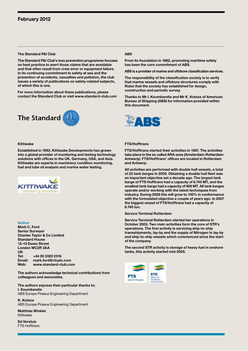
USING FUEL OIL ONBOARD SHIPS
A MASTER’S GUIDE TO:
The Standard P&l Club
The Standard P&I Club’s loss prevention programme focuses on best practice to avert those claims that are avoidable and that often result from crew error or equipment failure. In its continuing commitment to safety at sea and the prevention of accidents, casualties and pollution, the club issues a variety of publications on safety-related subjects, of which this is one.
For more information about these publications, please contact the Standard Club or visit www.standard-club.com
ABS
From its foundation in 1862, promoting maritime safety has been the core commitment of ABS.
ABS is a provider of marine and offshore classification services.
The responsibility of the classification society is to verify that marine vessels and offshore structures comply with Rules that the society has established for design, construction and periodic survey.
Thanks to Mr I. Koumbarelis and Mr K. Kotsos of American Bureau of Shipping (ABS) for information provided within this document.
Kittiwake
Established in 1993, Kittiwake Developments has grown into a global provider of monitoring and testing technology solutions with offices in the UK, Germany, USA, and Asia. Kittiwake are experts in machinery condition monitoring, fuel and lube oil analysis and marine water testing.
FTS/Hofftrans
FTS/Hofftrans started their activities in 1987. The activities take place in the so called ARA-area (Amsterdam-Rotterdam-Antwerp). FTS/Hofftrans’ offices are located in Rotterdam and Antwerp.
All activities are performed with double hull vessels, a total of 23 tank barges in 2009. Obtaining a double hull fleet was an important objective set a decade ago. The largest tank barge of FTS Hofftrans had a capacity of 6.745 MT, and the smallest tank barge had a capacity of 900 MT. All tank barges operate and/or working with the latest techniques from industry. During 2008 this will grow to 100% in conformance with the formulated objective a couple of years ago. In 2007 the biggest vessel of FTS/Hofftrans had a capacity of 6.745 ton.
Service Terminal Rotterdam
Service Terminal Rotterdam started her operations in October 2003. Two main activities form the core of STR’s operations. The first activity is servicing ship-to-ship transshipments, lay-by and the supply of Nitrogen to lay-by and ship-to-ship vessels which commenced since the start of the company.
The second STR activity is storage of heavy fuel in onshore tanks, this activity started mid-2005.
February 2012
AuthorMark C. FordSenior SurveyorCharles Taylor & Co LimitedStandard House12–13 Essex StreetLondon WC2R 3AAUKTel: +44 20 3320 2316Email: [email protected]: www.standard-club.com
The authors acknowledge technical contributions from colleagues and associates.
The authors express their particular thanks to:I. KoumbarelisABS Europe Piraeus Engineering Department
K. Kotsos ABS Europe Piraeus Engineering Department
Matthias WinklerKittiwake
Ed VersluisFTS Hofftrans
01A MASTER’S GUIDE TO: USING FUEL OIL ONBOARD SHIPSSTANDARD CLUB
contents
01 Introduction 03
02 Fuel oil and insurance claims 04 What is fuel oil? 04
03 Bunkering 08 Responsibility 09 Bunker plan 10 Communication 10 Pollution prevention measures 11 Tank capacities 14 Bunker checklists 16 Bunker system set-up 17 Continuous checks 18 Fuel delivery dubious practices 18 Flowmeter readings 18 Completion 22 Sampling and analysis 23 Onboard testing 26 Fuel quality 27 Bunker system maintenance 35
04 Documentation 36 Charterparty clauses 36 Bunker Supply Contracts 38 Bunkering instructions 38 Oil Record Book 38 Bunker receipts 40 Letters of protest 40 Fuel oil analysis reports 41
05 Storage 42 Heating 42 Bunker capacity 43 Settling tanks 43 Safety 43 Service tanks 44 Guidance in preparation for fuel changeover 45 Fuel changeover procedure basic guidelines 46 Sludge and fuel oil leakage tanks 48
06 Processing 51 Fuel transfer 51 Settling tanks to service tanks 51 Centrifugal separation (purifiers) 51 Filtration 54 Viscosity control 55
07 Machinery using fuel oil 56 Main engines and boilers 56 Leakage protection 60 Firefighting 60
PAGE
02 STANDARD CLUB A MASTER’S GUIDE TO: USING FUEL OIL ONBOARD SHIPS
contents
08 Additional precautions 61 Cleanliness 61 Management of change 61 Familiarisation 61 Bunker fuel tagging 62
09 Regulations and standards 63 MARPOL 63 The current and future regulations for MARPOL Annex VI 64
10 Glossary 68
Poster and checklist
03A MASTER’S GUIDE TO: USING FUEL OIL ONBOARD SHIPSSTANDARD CLUB
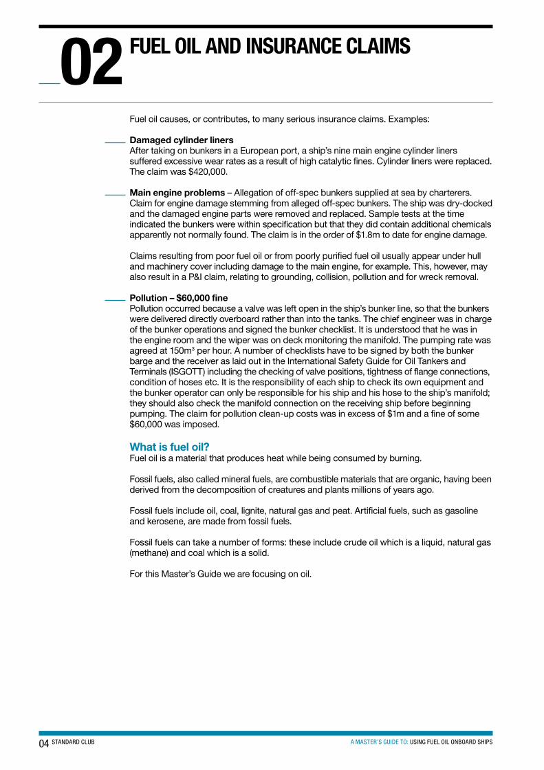
The purpose of this guide is to provide masters, ships’ officers and shore superintendents with a basic knowledge of the use of, and precautions to be taken when using fuel oils onboard ship.
The misuse of fuel oil can lead to major claims and jeopardise the safety of the ship.
They say that ‘oil and water do not mix’; today the master has to be very much aware of what is happening in the engine room.
Fuel oil has been used onboard ship since the 1870s when the SS Constantine first sailed the Caspian Sea using oil in her boilers to generate steam for the main propulsion system.
Now, most merchant tonnage primarily burns fuel oil to produce power for propulsion purposes, electrical power generation, in boilers or all of these.
Shipowners are faced with significant fuel cost fluctuations and changing emissions regulations, both of which determine the way fuel systems and diesel engines onboard are operated. This can cause various engine fuel system operational problems, such as purifier or filter clogging, fuel pump scoring or failure, severe cylinder liner wear, fuel injector seizure, exhaust valve seat corrosion or blow-past and turbocharger turbine wheel fouling. This is just a shortlist of potential problems.
We shall be mainly looking at the use of residual fuel oil (Heavy Fuel Oil/Intermediate Fuel Oil (commonly referred to as HFO/IFO) which usually has a viscosity of around 380cst/180cst respectively.) The use of HFO/IFO onboard ship can be very problematic. We will be paying particular attention to bunkering, storage, processing, machinery using HFO and the current and future regulations regarding fuel onboard ship. However, the majority of practices followed for HFO in this guide also relate to the distillate fuel marine diesel oil/gas oil (commonly referred to as MDO/MGO) used on ships.
We aim to raise awareness of the problems encountered with the storage, handling and processing of HFO onboard ship that can, if not approached in a safe and proficient manner, result in catastrophic loss of life, loss of the ship or a major pollution incident. We shall show that the good management and understanding of HFO will present less risk of a heavy fuel oil problem arising and result in a safer, cleaner and a more reliable ship.
Author: Editor:Mark C. Ford – Chief Engineer Capt. Chris Spencer Senior Surveyor, Standard Club Director Loss Prevention, Standard Club
IntRoDUctIon01
04 STANDARD CLUB A MASTER’S GUIDE TO: USING FUEL OIL ONBOARD SHIPS
Fuel oil causes, or contributes, to many serious insurance claims. Examples:
Damaged cylinder liners After taking on bunkers in a European port, a ship’s nine main engine cylinder liners suffered excessive wear rates as a result of high catalytic fines. Cylinder liners were replaced. The claim was $420,000.
Main engine problems – Allegation of off-spec bunkers supplied at sea by charterers.Claim for engine damage stemming from alleged off-spec bunkers. The ship was dry-docked and the damaged engine parts were removed and replaced. Sample tests at the time indicated the bunkers were within specification but that they did contain additional chemicals apparently not normally found. The claim is in the order of $1.8m to date for engine damage.
Claims resulting from poor fuel oil or from poorly purified fuel oil usually appear under hull and machinery cover including damage to the main engine, for example. This, however, may also result in a P&I claim, relating to grounding, collision, pollution and for wreck removal.
Pollution – $60,000 finePollution occurred because a valve was left open in the ship’s bunker line, so that the bunkers were delivered directly overboard rather than into the tanks. The chief engineer was in charge of the bunker operations and signed the bunker checklist. It is understood that he was in the engine room and the wiper was on deck monitoring the manifold. The pumping rate was agreed at 150m3 per hour. A number of checklists have to be signed by both the bunker barge and the receiver as laid out in the International Safety Guide for Oil Tankers and Terminals (ISGOTT) including the checking of valve positions, tightness of flange connections, condition of hoses etc. It is the responsibility of each ship to check its own equipment and the bunker operator can only be responsible for his ship and his hose to the ship’s manifold; they should also check the manifold connection on the receiving ship before beginning pumping. The claim for pollution clean-up costs was in excess of $1m and a fine of some $60,000 was imposed.
What is fuel oil?Fuel oil is a material that produces heat while being consumed by burning.
Fossil fuels, also called mineral fuels, are combustible materials that are organic, having been derived from the decomposition of creatures and plants millions of years ago.
Fossil fuels include oil, coal, lignite, natural gas and peat. Artificial fuels, such as gasoline and kerosene, are made from fossil fuels.
Fossil fuels can take a number of forms: these include crude oil which is a liquid, natural gas (methane) and coal which is a solid.
For this Master’s Guide we are focusing on oil.
FUeL oIL AnD InsURAnce cLAIMs02
05A MASTER’S GUIDE TO: USING FUEL OIL ONBOARD SHIPSSTANDARD CLUB
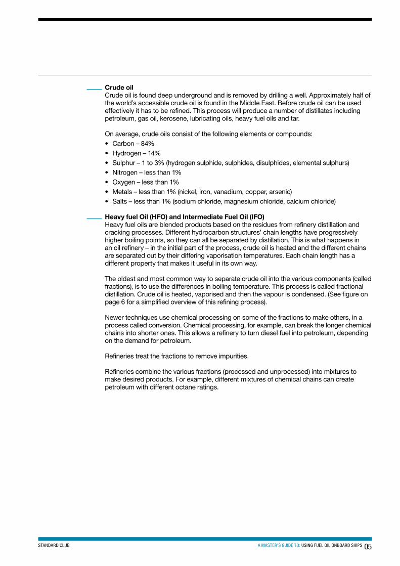
Crude oilCrude oil is found deep underground and is removed by drilling a well. Approximately half of the world’s accessible crude oil is found in the Middle East. Before crude oil can be used effectively it has to be refined. This process will produce a number of distillates including petroleum, gas oil, kerosene, lubricating oils, heavy fuel oils and tar.
On average, crude oils consist of the following elements or compounds:• Carbon – 84% • Hydrogen – 14% • Sulphur – 1 to 3% (hydrogen sulphide, sulphides, disulphides, elemental sulphurs) • Nitrogen – less than 1% • Oxygen – less than 1% • Metals – less than 1% (nickel, iron, vanadium, copper, arsenic) • Salts – less than 1% (sodium chloride, magnesium chloride, calcium chloride)
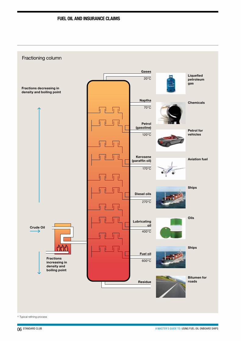
Heavy fuel Oil (HFO) and Intermediate Fuel Oil (IFO)Heavy fuel oils are blended products based on the residues from refinery distillation and cracking processes. Different hydrocarbon structures’ chain lengths have progressively higher boiling points, so they can all be separated by distillation. This is what happens in an oil refinery – in the initial part of the process, crude oil is heated and the different chains are separated out by their differing vaporisation temperatures. Each chain length has a different property that makes it useful in its own way.
The oldest and most common way to separate crude oil into the various components (called fractions), is to use the differences in boiling temperature. This process is called fractional distillation. Crude oil is heated, vaporised and then the vapour is condensed. (See figure on page 6 for a simplified overview of this refining process).
Newer techniques use chemical processing on some of the fractions to make others, in a process called conversion. Chemical processing, for example, can break the longer chemical chains into shorter ones. This allows a refinery to turn diesel fuel into petroleum, depending on the demand for petroleum.
Refineries treat the fractions to remove impurities.
Refineries combine the various fractions (processed and unprocessed) into mixtures to make desired products. For example, different mixtures of chemical chains can create petroleum with different octane ratings.
06 STANDARD CLUB A MASTER’S GUIDE TO: USING FUEL OIL ONBOARD SHIPS
FUeL oIL AnD InsURAnce cLAIMs
Fractioning column
Kerosene(paraffin oil)
Petrol(gasoline)
Diesel oils
Naptha
GasesLiquefiedpetroleum gas
Chemicals
Petrol forvehicles
Lubricating oil
Fuel oil
Residue
120°C
270°C
70°C
20°C
400°C
600°C
170°C
Ships
Oils
Ships
Bitumen forroads
Fractions decreasing in density and boiling point
Crude Oil
Fractions increasing in density and boiling point
Aviation fuel
^ Typical refining process
07A MASTER’S GUIDE TO: USING FUEL OIL ONBOARD SHIPSSTANDARD CLUB
Secondary refining techniques, such as thermal cracking and catalytic cracking are commonly used to extract higher value products from crude oil. Thermal cracking uses a technique known as ‘visbreaking1’ to reduce the viscosity of the final residue. The result is that less cutter stock2 is required to reduce the residue to its desired viscosity3. Visbreaking produces a lower quality residue, with a higher density, higher carbon content and poor ignition quality.
Catalytic cracking is perhaps the most important secondary refining process. Aluminium silicates are used as the catalysts to further remove high value components, particularly gasoline. Heavy gas oils, or cycle oils, are also produced. These are often used as cutter stocks with visbreaking residues to produce residual fuel oils. The residue from the cracking process is termed ‘slurry oil’. This slurry tends to be highly aromatic and of poor ignition quality but can be blended with the final residual fuel oil. The catalyst components are expensive, and are therefore recovered. Some, however, can find their way into the finished product (catalytic fines). As the name implies, residual fuel oil is produced from the residue of the refining process.
Catalytic fines remaining in bunkers are a major cause of damage to diesel engines. As will be explained later, this is one reason why fuel oil analysis is so important.
Heavy fuel oil is a general term, and other names commonly used to describe this range of products include: residual fuel oil, bunker fuel, bunker C, fuel oil No. 6, industrial fuel oil, marine fuel oil and black oil. In addition, terms such as heavy fuel oil, intermediate fuel oil and light fuel oil are used to describe products for industrial applications, to give a general indication of the viscosity and density of the product. Heavy Fuel Oil (HFO) is so named because of its high viscosity; it almost resembles tar when cold. They require heating for storage and combustion. Heavy fuel oils are used widely in marine applications in combustion equipment such as main engines, auxiliary engines and boilers. Due to the refining process becoming more sophisticated to extract more higher value fuels. The heavy fuel oils contain less higher quality fractions and are moving slowly towards the bottom end of the scale approaching bitumens.
As a residual product, HFO is a relatively inexpensive fuel – typically its costs around 30% less than distillate fuels. It has become the standard fuel for large, slow speed marine diesel engines, this being especially so during the oil crises of the 1970s and 1980s. Its use required extensive research and development of the fuel injection system and other components of low and medium speed engines.
1 Visbreaking is a non-catalytic thermal process that converts atmospheric or vacuum residues via thermal cracking to gas, naphtha, distillates, and visbroken residue. Atmospheric and vacuum residues are typically charged to a visbreaker to reduce fuel oil viscosity and increase distillate yield in the refinery.
2 A refinery stream used to thin a fuel oil or gasoil. Viscosity reduction and sulphur level adjustment provide most of the requirement for the cutter stock.
3 Viscosity is the resistance of a liquid to shear forces (and hence to flow).
08 STANDARD CLUB A MASTER’S GUIDE TO: USING FUEL OIL ONBOARD SHIPS
BUnKeRInG
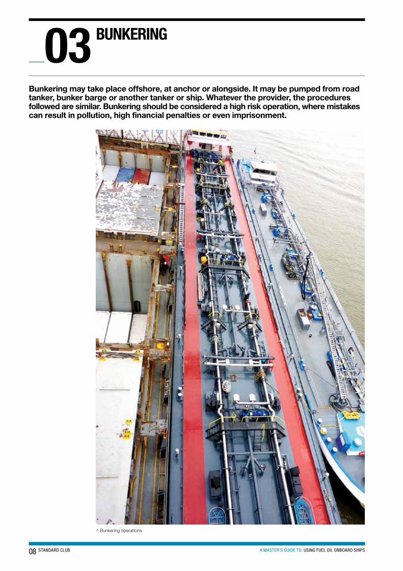
Bunkering may take place offshore, at anchor or alongside. It may be pumped from road tanker, bunker barge or another tanker or ship. Whatever the provider, the procedures followed are similar. Bunkering should be considered a high risk operation, where mistakes can result in pollution, high financial penalties or even imprisonment.
03
^ Bunkering operations
09A MASTER’S GUIDE TO: USING FUEL OIL ONBOARD SHIPSSTANDARD CLUB
Ships burning HFO in combustion equipment will, at some time in the voyage cycle, have to bunker fuel to replenish what has been consumed.
One of the most important procedures of a bunkering operation is attention to the ‘checklists’. The procedures and lists form part of a company’s safety management system (SMS) which follow the International Safety Management (ISM) Code.
As stated in the ISM Code in section 1.2.1:
“The objectives of the Code are to ensure safety at sea, prevention of human injury or loss of life, and avoidance of damage to the environment, in particular to the marine environment and to property.”
Bunkering checklists should be implemented to reduce the risk of negligence and other operational errors. They must be followed in consultation with the chief engineer, as he is normally the designated officer-in-charge of the bunkering operation. Before bunkering, usually a junior engineering officer takes ‘soundings’ of bunker tanks and calculates the volume of fuel oil available in every fuel oil tank on the ship. Then a bunker plan is prepared for the distribution of the fuel oil to be received.
ResponsibilityThe Master is responsible for all that happens on a ship. The Chief Engineer should be responsible for matters that concern the engine room including fuel oil systems and bunkering. Taking fuel oil (bunkering) is a potentially high risk operation and therefore it should always be the Chief Engineer’s responsibility. This should be clearly stated in the company safety management system. If certain tasks are delegated they should be monitored and checked by the Chief Engineer. The Master should always be aware of these responsibilities.
Case studyA ship was bunkering in a major Asian port. The bunkering operation was nearing completion and had stopped to calculate quantities that remained to be bunkered in the one tank being topped up.
The Chief Engineer was in his cabin and had ‘delegated’ the task of bunkering to the junior engineer. The junior engineer had not been on the ship very long. The junior engineer made a mistake in calculating the remaining available space in the tank and asked for a further additional amount of bunkers to be stemmed.
Due to the fact that the bunker tank was nearly full, heavy fuel oil bunkers spilled out from the air vent pipes and into the water.
The authorities subsequently fined the ship and master and imprisoned the Master, chief engineer and junior engineer.
ConclusionCompanies should ensure that proper bunker procedures are maintained.
Masters should always ensure they are satisfied that bunkering operations are always carried out in a correct manner.
10 STANDARD CLUB A MASTER’S GUIDE TO: USING FUEL OIL ONBOARD SHIPS
BUnKeRInG
The following is a list of the essentials to be carried out before, during and after bunkering.
Bunker planThe bunker plan is a piping (schematic) diagram that is accurate and representative of the bunkering system onboard. The plan should show the distribution of the bunkers and be posted by the bunkering station during bunkering, and must be fully understood and signed by the officers involved in the operation. Ideally it should show the amount of fuel onboard the ship before commencing bunkers, the amount of fuel to be bunkered and the plan of distribution of bunkers with tank soundings expected upon completion. A copy of the bunker tank sounding tables should be available to all personnel and form part of the bunker plan.
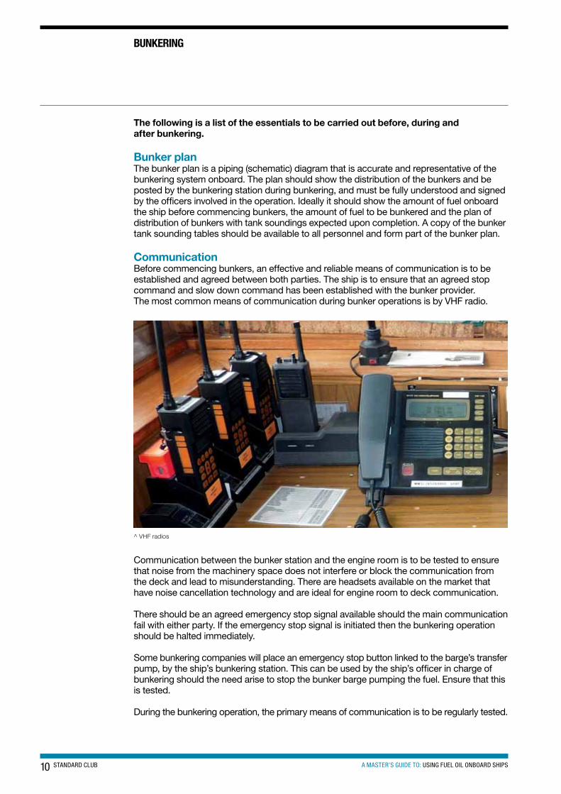
CommunicationBefore commencing bunkers, an effective and reliable means of communication is to be established and agreed between both parties. The ship is to ensure that an agreed stop command and slow down command has been established with the bunker provider. The most common means of communication during bunker operations is by VHF radio.
^ VHF radios
Communication between the bunker station and the engine room is to be tested to ensure that noise from the machinery space does not interfere or block the communication from the deck and lead to misunderstanding. There are headsets available on the market that have noise cancellation technology and are ideal for engine room to deck communication.
There should be an agreed emergency stop signal available should the main communication fail with either party. If the emergency stop signal is initiated then the bunkering operation should be halted immediately.
Some bunkering companies will place an emergency stop button linked to the barge’s transfer pump, by the ship’s bunkering station. This can be used by the ship’s officer in charge of bunkering should the need arise to stop the bunker barge pumping the fuel. Ensure that this is tested.
During the bunkering operation, the primary means of communication is to be regularly tested.
11A MASTER’S GUIDE TO: USING FUEL OIL ONBOARD SHIPSSTANDARD CLUB
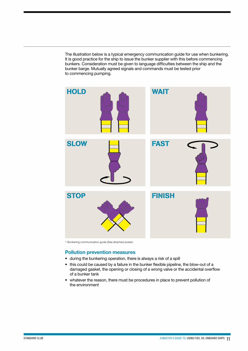
The illustration below is a typical emergency communication guide for use when bunkering. It is good practice for the ship to issue the bunker supplier with this before commencing bunkers. Consideration must be given to language difficulties between the ship and the bunker barge. Mutually agreed signals and commands must be tested prior to commencing pumping.
SLOW
HOLD
FINISH
FAST
STOP
WAIT
^ Bunkering communication guide (See attached poster)
Pollution prevention measures• during the bunkering operation, there is always a risk of a spill• this could be caused by a failure in the bunker flexible pipeline, the blow-out of a
damaged gasket, the opening or closing of a wrong valve or the accidental overflow of a bunker tank
• whatever the reason, there must be procedures in place to prevent pollution of the environment
12 STANDARD CLUB A MASTER’S GUIDE TO: USING FUEL OIL ONBOARD SHIPS
BUnKeRInG
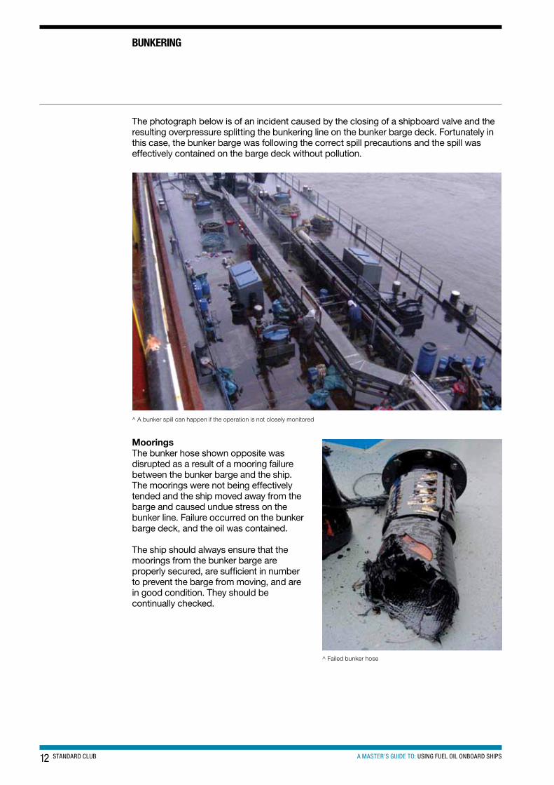
The photograph below is of an incident caused by the closing of a shipboard valve and the resulting overpressure splitting the bunkering line on the bunker barge deck. Fortunately in this case, the bunker barge was following the correct spill precautions and the spill was effectively contained on the barge deck without pollution.
^ A bunker spill can happen if the operation is not closely monitored
MooringsThe bunker hose shown opposite was disrupted as a result of a mooring failure between the bunker barge and the ship. The moorings were not being effectively tended and the ship moved away from the barge and caused undue stress on the bunker line. Failure occurred on the bunker barge deck, and the oil was contained.
The ship should always ensure that the moorings from the bunker barge are properly secured, are sufficient in number to prevent the barge from moving, and are in good condition. They should be continually checked.
^ Failed bunker hose
13A MASTER’S GUIDE TO: USING FUEL OIL ONBOARD SHIPSSTANDARD CLUB
Particular attention should be given to the moorings in rivers and channels where passing traffic can force the moorings to surge and possibly break the fuel hose or hose connections.
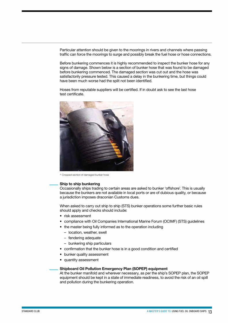
Before bunkering commences it is highly recommended to inspect the bunker hose for any signs of damage. Shown below is a section of bunker hose that was found to be damaged before bunkering commenced. The damaged section was cut out and the hose was satisfactorily pressure tested. This caused a delay in the bunkering time, but things could have been much worse had the split not been identified.
Hoses from reputable suppliers will be certified. If in doubt ask to see the last hose test certificate.
^ Cropped section of damaged bunker hose
Ship to ship bunkeringOccasionally ships trading to certain areas are asked to bunker ‘offshore’. This is usually because the bunkers are not available in local ports or are of dubious quality, or because a jurisdiction imposes draconian Customs dues.
When asked to carry out ship to ship (STS) bunker operations some further basic rules should apply and checks should include:• risk assessment• compliance with Oil Companies International Marine Forum (OCIMF) (STS) guidelines• the master being fully informed as to the operation including
– location, weather, swell – fendering adequate – bunkering ship particulars
• confirmation that the bunker hose is in a good condition and certified• bunker quality assessment• quantity assessment
Shipboard Oil Pollution Emergency Plan (SOPEP) equipmentAt the bunker manifold and wherever necessary, as per the ship’s SOPEP plan, the SOPEP equipment should be kept in a state of immediate readiness, to avoid the risk of an oil spill and pollution during the bunkering operation.
14 STANDARD CLUB A MASTER’S GUIDE TO: USING FUEL OIL ONBOARD SHIPS
BUnKeRInG
The SOPEP locker should have a minimum of these items:1. absorbent rolls2. absorbent pads3. absorbent granules4. absorbent materials5. brooms6. shovels7. mops8. scoops9. empty receptacles (200 litres capacity)10. portable air driven pumps11. oil boom for small spill containment12. oil spill dispersants
These items must be stowed in an easily accessible locker, clearly marked, and must be brought on deck ready for immediate use, prior to all bunkering operations.
As previously mentioned, emergency stop procedures must be in place and all scupper plugs and save-all plugs fitted to minimise oil pollution should a spill occur.
Tank capacitiesTank capacities should be monitored during bunkering by the use of soundings and/or ullages. Sometimes it is easier to use ullages if the bunker tank is large, as this saves time by not having to clean a large section of the sounding tape after each dip. Ullages should always be taken using the ullage pipe and reference to the ullage tables for tank contents used. Never use sounding pipes for ullages unless they have been specifically designed for this and the relevant ullage tables are used. Failure to use the correct tables for the sounding or ullage may result in a quantity miscalculation, and consequently an oil overflow.
Many ships have remote measuring systems that are safe, accurate and are class approved. The use of these remote systems, however, should not be taken for granted as without regular maintenance and testing these pieces of equipment may give false readings because of line blockages, air pressure failure or transmitter/electrical problems. Therefore before bunkering the remote readings should be cross-checked with manual soundings. This cross-check may be included in the ship’s planned maintenance routines.
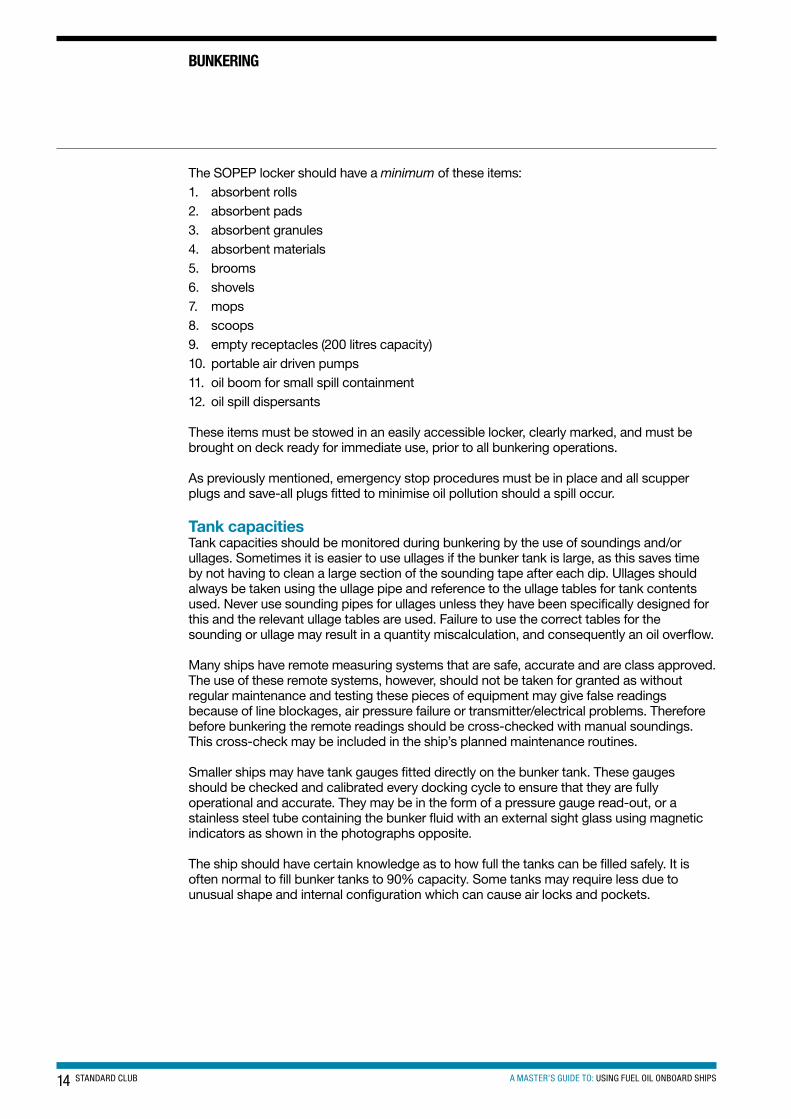
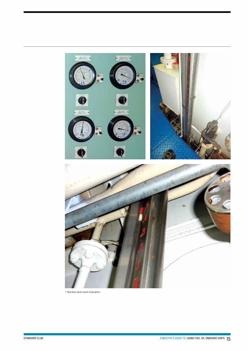
Smaller ships may have tank gauges fitted directly on the bunker tank. These gauges should be checked and calibrated every docking cycle to ensure that they are fully operational and accurate. They may be in the form of a pressure gauge read-out, or a stainless steel tube containing the bunker fluid with an external sight glass using magnetic indicators as shown in the photographs opposite.
The ship should have certain knowledge as to how full the tanks can be filled safely. It is often normal to fill bunker tanks to 90% capacity. Some tanks may require less due to unusual shape and internal configuration which can cause air locks and pockets.
15A MASTER’S GUIDE TO: USING FUEL OIL ONBOARD SHIPSSTANDARD CLUB
^ Bunker tank level indication
16 STANDARD CLUB A MASTER’S GUIDE TO: USING FUEL OIL ONBOARD SHIPS
BUnKeRInG
Bunker checklistsBunkering is a ‘high risk’ operation where mistakes can have significant consequences, including fines and imprisonment. Often there is considerable commercial pressure on the ship and ship’s staff. DO NOT commence bunkering until everything is properly prepared, checked and in place.
The bunker checklist is a very important document and is an integral part of the bunkering process. It is created as part of the ISM system and is ship specific. It should be drawn up and approved by the chief engineer. The checklist must be strictly followed and not just completed automatically. On many occasions, items on a bunker checklist have been checked off without verifying whether the requirements have been completed. This may well lead to a serious bunkering incident.
Bunkering is often carried out when the engineering staff are under pressure in respect of both time and manpower. Key checks are often missed and omissions only come to light when it is too late.
The checklist should at the very least include the items below.
Pre-bunkering checklist:1. state of adjacent waters reviewed and deemed acceptable2. ship properly secured (unless STS)3. check suppliers’ specification for the product corresponds to what was ordered4. agree quantity to be supplied and in what units (m³, tonnes, barrels etc)5. agree maximum pumping rate and line pressure at start, at maximum flow and at
the end6. ensure that the bunker barge checklist is understood and completed7. ensure that the bunker plan is understood and posted at the bunker station8. emergency stop for bunker barge transfer pump at the ship’s bunker station has been
tested if supplied9. ensure the MARPOL drip sampler is clean and fitted10. check correct bunker valves are open11. cross-check correct bunker valve set-up12. fuel oil daily service tanks at maximum safe working level, and filling valves closed13. warning signs in position, for instance ‘No Smoking’14. material safety data sheet for HFO is available15. SOPEP plan is available16. spill clean-up material readily available17. ensure all save-all and drip tray plugs are screwed in position18. provisions made to drain off any accumulations of sea or rain water on deck
during bunkering19. plug all deck scuppers and ensure they are oil and watertight20. foam fire extinguisher placed at bunker station21. purifiers and transfer pumps off22. check that the sounding and ullage pipe caps are screwed down, unless dipping a tank
17A MASTER’S GUIDE TO: USING FUEL OIL ONBOARD SHIPSSTANDARD CLUB
23. check that the air vents and flame arrestors for the bunker tanks are intact and free from blockages
24. re-confirm remaining space in bunker tanks to be filled25. check bunker tank high level alarms if fitted26. ensure that the designated overflow tank and overflow sight glasses/alarms are
prepared and monitored27. agree stop and start signals between ship and barge or road tanker28. bravo flag flying and red light showing at night29. agree emergency shutdown procedure30. ensure all fire precautions are observed31. all hot work permits should have been suspended for the duration of bunkering32. check hose and couplings are secure and in good order33. fuel connection and hose secured to vessel34. check barge or road tanker flowmeter tamper seal and check soundings on barge
or road tanker35. carry out a spot analysis or compatibility test if ship has the test kit36. check on shipboard flowmeter37. ensure ship and barge moorings will be tended during bunkering38. bunker manifold valve open39. unused manifold connections isolated and blanked off40. all ship communications confirmed as operational41. all ship to shore or barge communications agreed and operational42. officer on watch/master informed43. signal pumping to commence
Bunker system set-upIt is imperative that all engineering officers are fully aware of the fuel oil bunkering system. The chief engineer should allow only engineers who are familiar with the system to be actively involved in bunkering operations. The master should be fully aware during bunker operations of the quantities to be received, bunker distribution, start time, officers-in-charge, expected time of completion, and be in communication with all involved.
Before pumping starts, the tank receiving the fuel should be identified by the officer-in-charge and the correct system valves opened and tagged with easily identifiable valve positions. All other system valves should be checked and tagged as being closed. The system may then be cross-checked by another competent officer to ensure it is in a state of readiness to accept fuel delivery. It is recommended that this cross-check of the system set-up is part of the bunker checklist.
When commencing the bunkers, ensure that the pumping rate is very slow to enable the system to be checked for leaks and that the fuel is being received in the desired location. Once this has been verified, the pumping rate can be increased to the safest maximum rate, ensuring that the bunker line maximum pressure is monitored and not exceeded.
18 STANDARD CLUB A MASTER’S GUIDE TO: USING FUEL OIL ONBOARD SHIPS
Continuous checksThe chief engineer should always be in overall charge of the bunkering operation.
During bunkering procedures:1. witness taking and sealing of a minimum of three representative product samples2. check the bunker line pressure regularly to ensure it is not too high3. check and record the temperature of the fuel as it is pumped on board4. monitor fuel connections for leaks and fuel flow5. monitor the sight glass in the engine room to ensure no overflow is taking place6. changeover tanks whenever necessary. (Always open the other tank before isolating
the full one)7. check the rate at which bunkers are received8. check the tightness and slackness of mooring ropes9. check trim and list of the bunker barge and the ship10. continuous monitoring and look-outs for the ship’s position and mooring arrangements
when at anchor
Fuel delivery dubious practicesThe vast majority of companies involved in the fuel oil supply and bunkering industry carry out their business in an honest and professional manner. The behaviour of a few individuals can cast a shadow over the whole industry, but genuine mistakes can be made. It is important to be aware of the type of malpractice which has occurred and may be used again.
Such malpractice can result in bunker claims.
Fuel oil delivery: quantityOne method of adjusting the delivered quantity of fuel oil is by measuring twice. This is done by transferring the fuel from one tank to another by gravity during taking of the opening readings. One of the first tank quantities measured is then dropped under gravity to a convenient slack tank which will be measured last. Usually this is achieved by transferring from a fuel tank aft to a slack tank forward, the gauging having been started in the aft tanks.
Counter measure – re-check the first tanks measured before delivery begins.
Ullage and soundingsThe delivery barge contends that seals on sounding and ullage pipes cannot be broken. The deceit is usually backed by pretexts such as Customs seals or a seized sounding cock.
Usually the only alternative to gauging the tanks is by measurement through a flowmeter. Be wary of air being introduced through the meter to increase the measured delivery displayed. This is commonly called the ‘cappuccino effect’ (see below).
Counter measures – do not agree to meter only fuel oil deliveries. If Customs seals are cited, issue a letter of protest, or comment on the bunker delivery receipt with counter-signature from barge master.
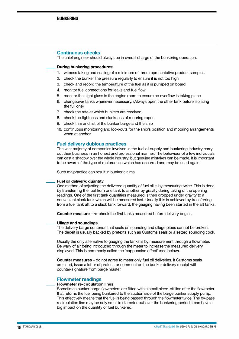
Flowmeter readingsFlowmeter re-circulation linesSometimes bunker barge flowmeters are fitted with a small bleed-off line after the flowmeter that returns the fuel being bunkered to the suction side of the barge bunker supply pump. This effectively means that the fuel is being passed through the flowmeter twice. The by-pass recirculation line may be only small in diameter but over the bunkering period it can have a big impact on the quantity of fuel bunkered.
BUnKeRInG
19A MASTER’S GUIDE TO: USING FUEL OIL ONBOARD SHIPSSTANDARD CLUB
Counter measures – check for any suspicious lines after the barge’s flowmeter. Use the ship’s flowmeter (if fitted) as a cross check and question any major differences. Ask to see the bunker barge’s flowmeter calibration certificate and check that the flowmeter seal is intact. Refer to the bunker barge cargo piping diagram to assist with the checking of any suspicious lines.
The cappuccino effectAir is sometimes intentionally introduced by the supplier during the pumping of bunkers to the ship which aerates the fuel being delivered. The common standard type flowmeter will not measure the quantity of fuel being delivered but the volume of throughput. If the fuel has been aerated, this volume is made up of fuel and small air bubbles. Thus the quantity of fuel being delivered is on some occasions considerably less than stated, because the flowmeter, which measures the volume going through it, reacts to both the bunker fuel and the low-density entrapped air and registers this as a large volume of oil. The mass of the entrapped air, however, is so small that it does not contribute significantly to the total mass of the mixture. When the bunker tanks are sounded, the soundings also appears correct as the entrapped air is still in suspension in the fuel. When the air eventually settles out of the fuel oil the level of the bunker tank drops. This indicates an apparent onboard fuel loss at the next sounding. Depending on the amount of bunkers requested, the fuel shortage can be considerable and amount to a heavy financial loss, or result in a bunker claim.
This practice is commonly referred to as the ‘cappuccino’ effect.
Counter-measures – use a density meter to check the density. There are meters available that can measure the true quantity of the fuel being delivered. Coriolis meters provide continuous, on-line measurement of mass flow rate, volume flow rate, density, temperature, and batch totals – all from a single device. Coriolis meters have no moving parts or obstructions in contact with the fluid being measured and require little maintenance, flow conditioning or straight pipe runs. Unlike volume measurement, mass measurement is independent of operating pressure and temperature, which obviates the need for error-prone density conversions. For highly viscous fluids where entrained gas and air is unable to escape, direct mass flow measurement can perform better than volumetric meters and tank gauges. The Coriolis meter will give a more accurate measurement of the quantity of fuel oil delivered. These meters can be expensive and may require system piping modifications.
Combating the cappuccino effect for bunkersBefore loading bunkers from a barge, the following checks should be carried out in addition to the ship’s bunkering procedure:• board the bunker barge and verify, by sounding the barge’s fuel oil cargo tanks and using
corresponding sounding tables, the quantity of fuel onboard the barge before bunkering commences
• if possible, obtain draft readings of the bunker barge before pumping begins• check the sounding tape when sounding the fuel tanks both on the barge and during
bunkering for any evidence of air bubbles in the fuel• ask to see the barge’s cargo pump that will be used for fuel delivery and check for any
suspect air connections. These may be quite small• ask the crew how they intend to blow the lines after completion of bunkering and ask to
inspect this arrangement before starting fuel transfer, to limit the opportunity to introduce air with the oil flowing
• check the barge’s flowmeter reading and confirm that the calibration certificate is for the meter in question and is valid. Confirm that the meter’s calibration seal is intact
• check for suspicious flowmeter recirculation lines. These may be small but can have a big impact on the quantity received onboard
20 STANDARD CLUB A MASTER’S GUIDE TO: USING FUEL OIL ONBOARD SHIPS
BUnKeRInG
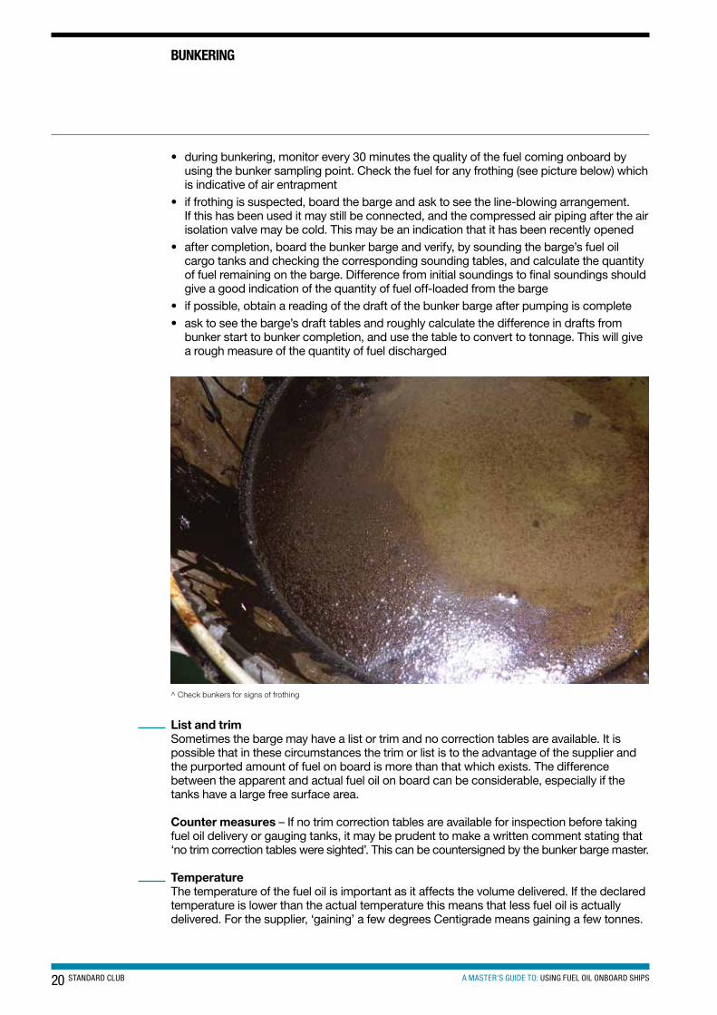
• during bunkering, monitor every 30 minutes the quality of the fuel coming onboard by using the bunker sampling point. Check the fuel for any frothing (see picture below) which is indicative of air entrapment
• if frothing is suspected, board the barge and ask to see the line-blowing arrangement. If this has been used it may still be connected, and the compressed air piping after the air isolation valve may be cold. This may be an indication that it has been recently opened
• after completion, board the bunker barge and verify, by sounding the barge’s fuel oil cargo tanks and checking the corresponding sounding tables, and calculate the quantity of fuel remaining on the barge. Difference from initial soundings to final soundings should give a good indication of the quantity of fuel off-loaded from the barge
• if possible, obtain a reading of the draft of the bunker barge after pumping is complete• ask to see the barge’s draft tables and roughly calculate the difference in drafts from
bunker start to bunker completion, and use the table to convert to tonnage. This will give a rough measure of the quantity of fuel discharged
^ Check bunkers for signs of frothing
List and trimSometimes the barge may have a list or trim and no correction tables are available. It is possible that in these circumstances the trim or list is to the advantage of the supplier and the purported amount of fuel on board is more than that which exists. The difference between the apparent and actual fuel oil on board can be considerable, especially if the tanks have a large free surface area.
Counter measures – If no trim correction tables are available for inspection before taking fuel oil delivery or gauging tanks, it may be prudent to make a written comment stating that ‘no trim correction tables were sighted’. This can be countersigned by the bunker barge master.
TemperatureThe temperature of the fuel oil is important as it affects the volume delivered. If the declared temperature is lower than the actual temperature this means that less fuel oil is actually delivered. For the supplier, ‘gaining’ a few degrees Centigrade means gaining a few tonnes.
21A MASTER’S GUIDE TO: USING FUEL OIL ONBOARD SHIPSSTANDARD CLUB
Counter measures – check and record the temperature during the initial gauging and periodically until completion.
Calibration tablesIt is not unknown for duplicate barge tables to be used. At first sight these appear to be in order but have, in fact, been modified to the advantage of the supplier. Inserted pages, photocopies, corrections, different print and paper types are all indications of tampering.
Counter measures – check if the tables are original or a copy – issue a letter of protest if unsure.
WaterIf 1,000 tonnes of fuel is bunkered and it contains 1% water, it is effectively just 990 tonnes of fuel. A loss of 10 tonnes of fuel resulting from water content is a loss of approximately $7,0004.
Water may be mixed with the fuel oil just before the bunkering takes place. ‘Sealed’ samples are taken from the barge before the water is introduced and used as ‘official’ supplier samples. Another trick is not using water-detecting paste on the sounding tape. Water-detecting paste can be used for distillate fuel deliveries but does not work with black residual fuels as you cannot see the colour change. Sometimes an incorrect alternative paste is used, like chrome cleaner, which looks and smells the same, but does not change colour on contact with water.
It is also possible that the supplier of fuel oil to the bunker barge has given the barge excess water. This can then be passed on to the customer who will be unaware of water being present. Bunker barges normally bunker fuel from the port oil terminals. The detection of excess water depends on the effectiveness of their procedures and checklists.
Salt water is sometimes delivered with fuels as a result of contamination by the bunker barge. There are many potential causes of this including ballast water contamination, structural defects and incorrect valve operation. A common source of sea water ingress is ballast water entering the ship’s bunker tank via a corroded sounding pipe. One of the main concerns over sea water contamination of fuel is that a chemical reaction between the sodium (salt) compounds in the water and the vanadium compounds in the fuel during combustion may cause high temperature corrosion (hot end corrosion). The vanadium and sodium oxidise during combustion, which causes sticky, low-melting point salts which adhere to exhaust valves, valve seats and turbocharger turbine blades which in turn attract other combustion deposits leading to mechanical damage.
It should be noted that the ISO 8217:2010 standards state that the maximum allowable water content for all heavy fuel oils should be not greater than 0.5%.
Excessive water represents a triple loss. Firstly, there is the loss of specific energy in the fuel which will affect the fuel consumption. Secondly, there is the cost of disposing of the water removed by the treatment system. Such water is unlikely to pass through a 15 PPM oily water separator, so it has to be retained for disposal later, with a cost to the ship operator. Thirdly, water will damage fuel injection equipment, cause corrosion and failure of exhaust valves and turbochargers.
Counter-measures – check using ‘Water in Oil’ test. Issue a letter of protest if the percentage of water content is more than stated on the bunker delivery receipt.
4 Fuel price as of February 2012.
22 STANDARD CLUB A MASTER’S GUIDE TO: USING FUEL OIL ONBOARD SHIPS
There are other less sophisticated, underhand methods of reducing the real quantity of fuel oil delivered. These include ‘unofficial’ piping between the storage tanks and other un-nominated tanks, such as cofferdams or void spaces.
Counter-measures – fundamentally, the care, diligence and training of the staff responsible for fuel oil deliveries. The purchaser should obtain specification acceptance by the fuel supplier.
Summary• fuel oil purchasers need to advise the ship’s staff which grade of fuel they will receive and
how it will be transferred• fuels from different deliveries should be segregated as far as practicable• all receiving fuel oil tanks need to be gauged and the results recorded prior to taking
delivery of fuel• do not sign any documentation until you have witnessed the event referred to in the document• if the origin and method by which the supplier’s sample was obtained is unknown then
when signing for it, add the words ‘for receipt only – source unknown’• fuel oil samples should be taken by continuous-drip method throughout the bunkering• if the fuel oil delivered is supplied by more than one barge, a sample should be taken of
each fuel oil from the supplying barges• sign the bunker delivery receipt only for volume delivered. If the supplier insists on a
signature for weight add ‘for volume only – weight to be determined after density testing of representative sample’
CompletionPost-bunkering proceduresAfter pumping is completed, the bunker supplier may want to blow the line through with compressed air to ensure that all the fuel is out of the line before disconnection at the bunker manifold. It is critical to be aware of the safety implications of this line-blowing, and therefore:• ensure that pipe disconnection has not commenced before line-blowing• ensure that no system valves have been closed before line-blowing• take care in the vicinity of the bunker pipe as it may move violently during line-blowing• be aware that during disconnection a highly flammable oil mist may be present in the
bunker line caused by the blowing-though action. All safety precautions are to be followed closely
After pumping and line-blowing, the fuel quantity received must be checked and verified by using the ship’s normal methods, such as gauges, soundings, ullages, and flowmeter.
When the chief engineer is satisfied that the quantity received is correct then the bunker delivery receipt can be signed either by that officer or by the master.
The post-bunker checklist is as follows:1. bunker valve closed2. disconnect hose (drain and/or blow through before disconnecting)3. check barge or road tanker meter readings4. check ship’s meter reading and soundings for quantity verification5. sign Bunker Delivery Receipt5 BDR
5 The Bunker Delivery Receipt as specified in appendix V to MARPOL Annex VI, is to contain at least: name and IMO number of receiving ship, port, date of commencement of delivery, name, address and telephone number of marine fuel oil supplier, product name(s), quantity (metric tons), density at 15 deg. C (kg/m3), sulphur content (%) and a declaration signed and certified by the fuel oil supplier’s representative that the fuel oil supplied is in conformity with regulation 14.1 or 14.4 and regulation 18.3 of MARPOL Annex VI.
BUnKeRInG
23A MASTER’S GUIDE TO: USING FUEL OIL ONBOARD SHIPSSTANDARD CLUB
6. retain BDR with product sample7. return SOPEP to bridge8. clean-up equipment stowed back in the correct place9. bravo flag/red light stowed and switched off10. remove and pack away warning and safety signs11. foam fire extinguisher placed back in correct location12. complete Oil Record Book and confirm bunkering is complete13. master informed of completion
Sampling and analysisThere have been many claims involving bunkered fuel that failed to meet the required minimum specifications and caused engine breakdown and damage.
Remember that 500 tonnes of fuel, considered a small delivery, may cost $315,000 and the analysis fee is normally around $600. Fuel testing should not be seen by the shipowner as an avoidable expense, but a form of low cost insurance.
One the most important aspects of taking bunkers is fuel oil sampling. This covers the method of taking the sample, the location, and formal witnessing.
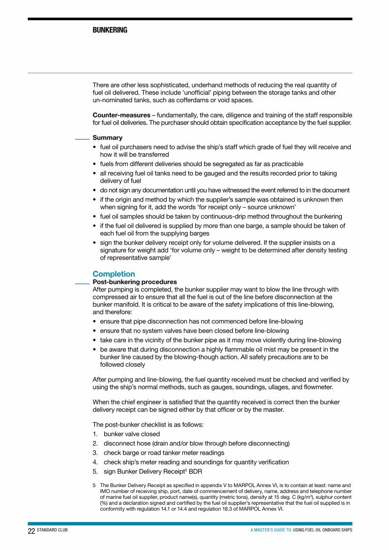
The importance of a suitably drawn and witnessed representative oil sample cannot be over-emphasised. It forms the basis of all discussion, debate or dispute resolution relating to the bunkering. The most common and most economic means of obtaining a representative sample is by using a drip type sampler, as pictured below.
^ Bunker sampling device
Maximum widthof Bunker Sampler
MUST �t between the �angeholes and have a diameterlarger than the inner pipediameter (B).
BOLTHOLES
FLANGE
BUNKER SAMPLER
A
B
C
^ Fuel oil sampler and cubitainer™ photo supplied by KITTIWAKE
Fuel oil sample collectionThe tube within the sampler and sample valve should always be cleaned before use. This can be achieved by removing the tube, simply flushing it with a clean distillate fuel and allowing it to drain thoroughly before installing. The use of low flashpoint solvents is not recommended for cleaning the sampler. The tube should always be installed with the holes facing the direction of flow. (See picture of fuel oil sampler and cubitainer).
24 STANDARD CLUB A MASTER’S GUIDE TO: USING FUEL OIL ONBOARD SHIPS
BUnKeRInG
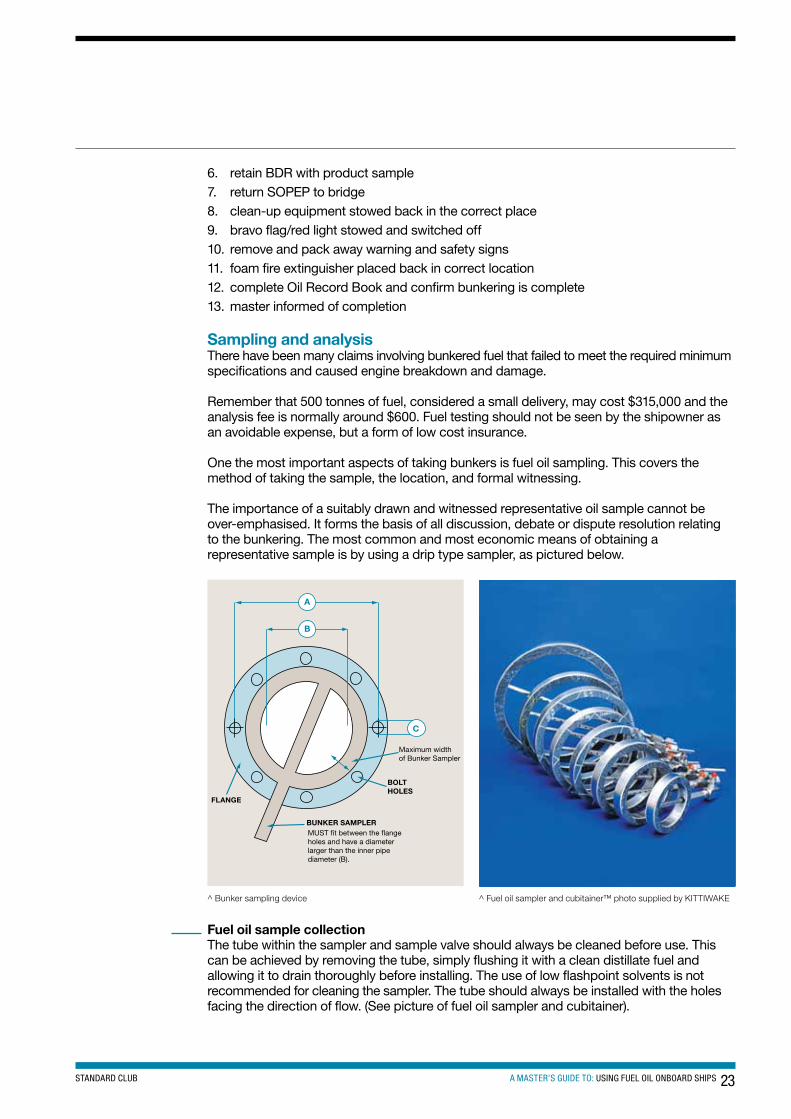
When bunkering starts, place a container under the sampler, open the sampler valve fully and flush the sampler with fuel. It is good practice to check this sample from fuel initially pumped onboard as it may be high in water content from the bunker barge’s tanks.
After flushing the sampler, close the valve and attach a suitable clean container to the valve. Adjust the needle valve to give a slow and steady drip. Time the fill rate so that it will provide for sufficient estimated sample over the expected delivery period.
^ MARPOL sample point showing cubitainer attached
If the sample container fills during the bunkering period, remove it and place an empty sample container (Cubitainer) on the sampler and continue to draw a sample.
On completion of bunkering, mix together the samples from both containers to ensure you have a good, representative sample from the bunkering operation.
• always ensure that the sampler valve is fully open to allow the sampler to drain• always close the sampler valve before blowing through the fuel lines on completion
of bunkering• close the sampler valve if pumping stops, to prevent the sample being drawn back,
under vacuum, into the fuel line
Select three or four clean sample bottles. The exact number depends on the final destination of the various samples. To cover all eventualities, it is recommended that four representative samples are obtained from the delivery. The distribution of the samples being: • supplier’s sample (from their MARPOL connection)• ship’s sample for retention on board• onboard analysis sample• sample for independent analysis
25A MASTER’S GUIDE TO: USING FUEL OIL ONBOARD SHIPSSTANDARD CLUB
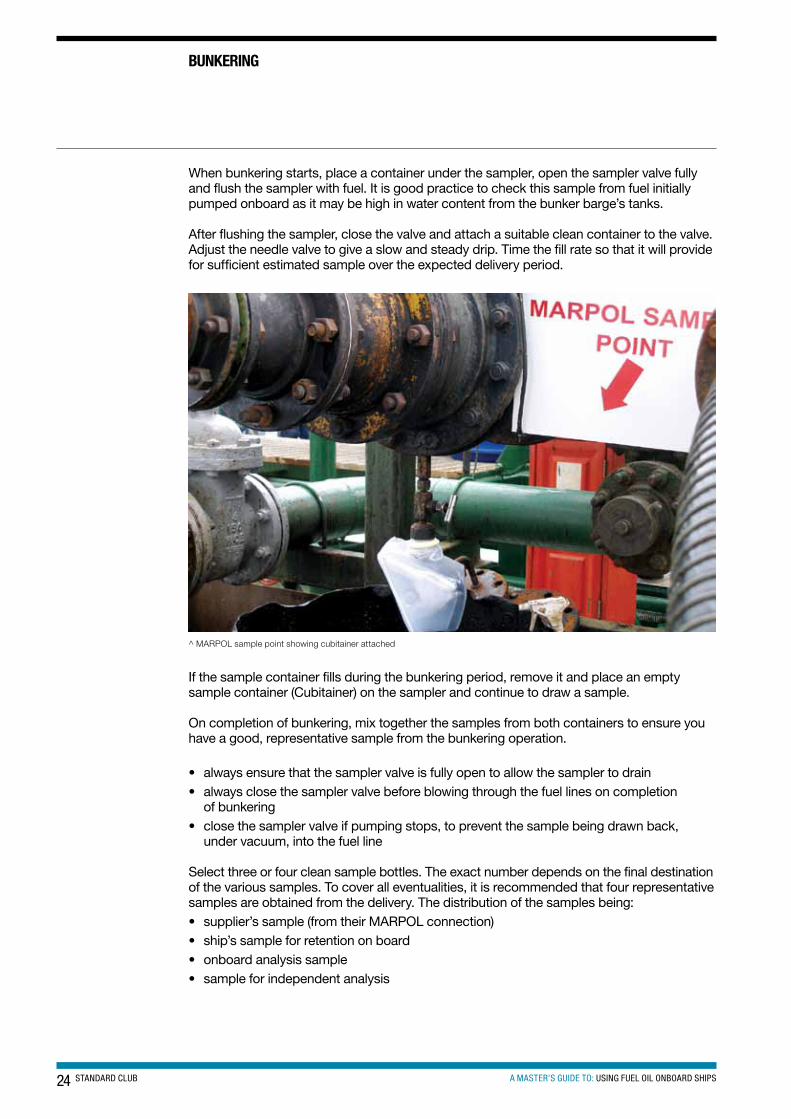
The full Cubitainer should be placed in the pourer box and thoroughly shaken to ensure that the contents are well mixed. Attach the pourer spout and gradually transfer the contents into the sample bottles, filling each a little at a time. If more than one Cubitainer was used during bunkering, then transfer a portion into each of the bottles. Complete the document labels and attach one to each sample bottle.
Always have the barge operator to witness the removal and sealing of the sample bottle(s) (shown below). If this request is refused, or if no witness is provided, then note this in the delivery log.
Bunker collection, sampling and storage guidelines are provided in Annex VI of MARPOL 73/78 and have been defined by MEPC 96(47), which states that:
“A retained sample of all fuel oils as supplied, is drawn at the ship’s receiving manifold, sealed, signed on behalf of the supplier and the Master or ship’s officer in charge of the bunkering operation. The retained sample is to be kept under the ship’s control until the subject fuel has been substantially consumed, but in any case for at least 12 months from the date of delivery.”
^ Fuel oil sampling bottle photo supplied by KITTIWAKE
It is important to remember that this sample is to be used solely to determine compliance with Annex VI of MARPOL 73/78 and cannot be used for commercial purposes. However, samples can be drawn at the same time for other purposes.
Summary• a representative sample is fundamental for all later testing• a continuous drip manual sampler is the proven method for effective sampling• the sample must be witnessed by all parties: the supplier’s representative as well as the
recipient/ship• the point for custody transfer is usually the ship’s bunker manifold• careful measurements during delivery will produce savings• samples should be handled and stored carefully – they may be the only evidence in the
event of a claim• IMO MARPOL Annex VI requires you to store the sample for at least 12 months and the
Bunker Delivery Receipt for three years.
26 STANDARD CLUB A MASTER’S GUIDE TO: USING FUEL OIL ONBOARD SHIPS
BUnKeRInG
Onboard testingFuel oil testing by a reputable analysis company is something that is carried out on most ships which bunker heavy fuel oil. Sometimes, however, a delay in receiving results of the analysis, or misplacing or loss of the samples, has resulted in the use of fuel that has caused serious problems. This is where basic onboard fuel testing can greatly assist is identifying potential fuel problems before use and long before the shore analysis results are received.
If, for whatever reason, a company decides that fuel analysis is not necessary, a full and formal risk analysis should be carried out to test that decision. The relatively minor costs of regular fuel oil analysis, compared to the price of the fuel, far outweigh the potential damage and costs associated with mechanical failure caused by poor fuel quality.
Conducting representative sampling, laboratory analysis and onboard testing provides an effective tool to identify poor quality fuel and a way of avoiding serious operational problems and expensive mechanical repairs.
There are numerous fuel testing organisations that offer good advice and equipment for fuel testing onboard. Below is an example of three onboard tests that can be carried out on fuel oil during or immediately after bunkering to determine fuel density, fuel compatibility and water content.
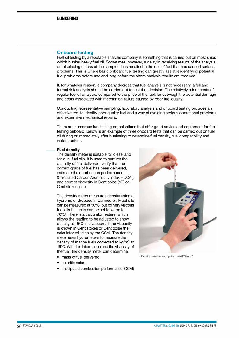
Fuel densityThe density meter is suitable for diesel and residual fuel oils. It is used to confirm the quantity of fuel delivered, verify that the correct grade of fuel has been delivered, estimate the combustion performance (Calculated Carbon Aromaticity Index – CCAI), and correct viscosity in Centipoise (cP) or Centistokes (cst).
The density meter measures density using a hydrometer dropped in warmed oil. Most oils can be measured at 50ºC, but for very viscous fuel oils the units can be set to warm to 70ºC. There is a calculator feature, which allows the reading to be adjusted to show density at 15ºC in a vacuum. If the viscosity is known in Centistokes or Centipoise the calculator will display the CCAI. The density meter uses hydrometers to measure the density of marine fuels corrected to kg/m3 at 15°C. With this information and the viscosity of the fuel, the density meter can determine: • mass of fuel delivered • calorific value • anticipated combustion performance (CCAI)
^ Density meter photo supplied by KITTIWAKE
27A MASTER’S GUIDE TO: USING FUEL OIL ONBOARD SHIPSSTANDARD CLUB
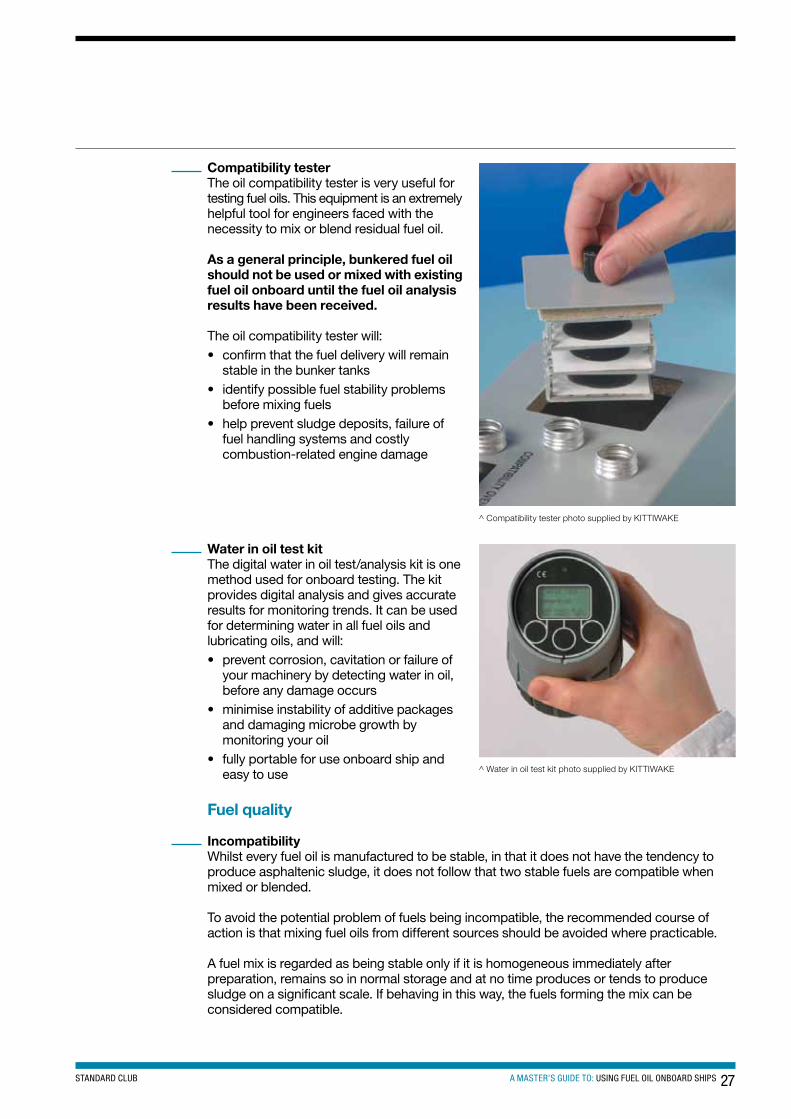
Compatibility testerThe oil compatibility tester is very useful for testing fuel oils. This equipment is an extremely helpful tool for engineers faced with the necessity to mix or blend residual fuel oil.
As a general principle, bunkered fuel oil should not be used or mixed with existing fuel oil onboard until the fuel oil analysis results have been received.
The oil compatibility tester will:• confirm that the fuel delivery will remain
stable in the bunker tanks • identify possible fuel stability problems
before mixing fuels • help prevent sludge deposits, failure of
fuel handling systems and costly combustion-related engine damage
^ Compatibility tester photo supplied by KITTIWAKE
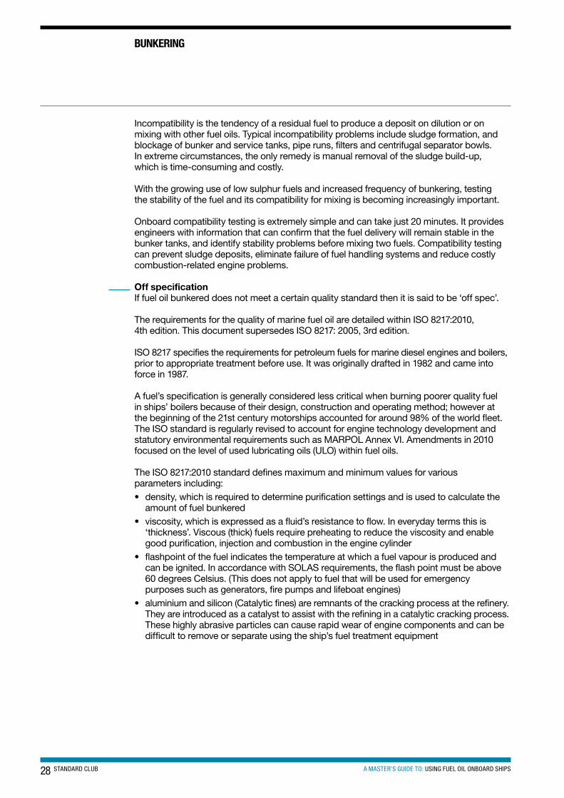
Water in oil test kitThe digital water in oil test/analysis kit is one method used for onboard testing. The kit provides digital analysis and gives accurate results for monitoring trends. It can be used for determining water in all fuel oils and lubricating oils, and will:• prevent corrosion, cavitation or failure of
your machinery by detecting water in oil, before any damage occurs
• minimise instability of additive packages and damaging microbe growth by monitoring your oil
• fully portable for use onboard ship and easy to use ^ Water in oil test kit photo supplied by KITTIWAKE
Fuel quality
IncompatibilityWhilst every fuel oil is manufactured to be stable, in that it does not have the tendency to produce asphaltenic sludge, it does not follow that two stable fuels are compatible when mixed or blended.
To avoid the potential problem of fuels being incompatible, the recommended course of action is that mixing fuel oils from different sources should be avoided where practicable.
A fuel mix is regarded as being stable only if it is homogeneous immediately after preparation, remains so in normal storage and at no time produces or tends to produce sludge on a significant scale. If behaving in this way, the fuels forming the mix can be considered compatible.
28 STANDARD CLUB A MASTER’S GUIDE TO: USING FUEL OIL ONBOARD SHIPS
Incompatibility is the tendency of a residual fuel to produce a deposit on dilution or on mixing with other fuel oils. Typical incompatibility problems include sludge formation, and blockage of bunker and service tanks, pipe runs, filters and centrifugal separator bowls. In extreme circumstances, the only remedy is manual removal of the sludge build-up, which is time-consuming and costly.
With the growing use of low sulphur fuels and increased frequency of bunkering, testing the stability of the fuel and its compatibility for mixing is becoming increasingly important.
Onboard compatibility testing is extremely simple and can take just 20 minutes. It provides engineers with information that can confirm that the fuel delivery will remain stable in the bunker tanks, and identify stability problems before mixing two fuels. Compatibility testing can prevent sludge deposits, eliminate failure of fuel handling systems and reduce costly combustion-related engine problems.
Off specificationIf fuel oil bunkered does not meet a certain quality standard then it is said to be ‘off spec’.
The requirements for the quality of marine fuel oil are detailed within ISO 8217:2010, 4th edition. This document supersedes ISO 8217: 2005, 3rd edition.
ISO 8217 specifies the requirements for petroleum fuels for marine diesel engines and boilers, prior to appropriate treatment before use. It was originally drafted in 1982 and came into force in 1987.
A fuel’s specification is generally considered less critical when burning poorer quality fuel in ships’ boilers because of their design, construction and operating method; however at the beginning of the 21st century motorships accounted for around 98% of the world fleet.The ISO standard is regularly revised to account for engine technology development and statutory environmental requirements such as MARPOL Annex VI. Amendments in 2010 focused on the level of used lubricating oils (ULO) within fuel oils.
The ISO 8217:2010 standard defines maximum and minimum values for various parameters including:• density, which is required to determine purification settings and is used to calculate the
amount of fuel bunkered• viscosity, which is expressed as a fluid’s resistance to flow. In everyday terms this is
‘thickness’. Viscous (thick) fuels require preheating to reduce the viscosity and enable good purification, injection and combustion in the engine cylinder
• flashpoint of the fuel indicates the temperature at which a fuel vapour is produced and can be ignited. In accordance with SOLAS requirements, the flash point must be above 60 degrees Celsius. (This does not apply to fuel that will be used for emergency purposes such as generators, fire pumps and lifeboat engines)
• aluminium and silicon (Catalytic fines) are remnants of the cracking process at the refinery. They are introduced as a catalyst to assist with the refining in a catalytic cracking process. These highly abrasive particles can cause rapid wear of engine components and can be difficult to remove or separate using the ship’s fuel treatment equipment
BUnKeRInG
29A MASTER’S GUIDE TO: USING FUEL OIL ONBOARD SHIPSSTANDARD CLUB
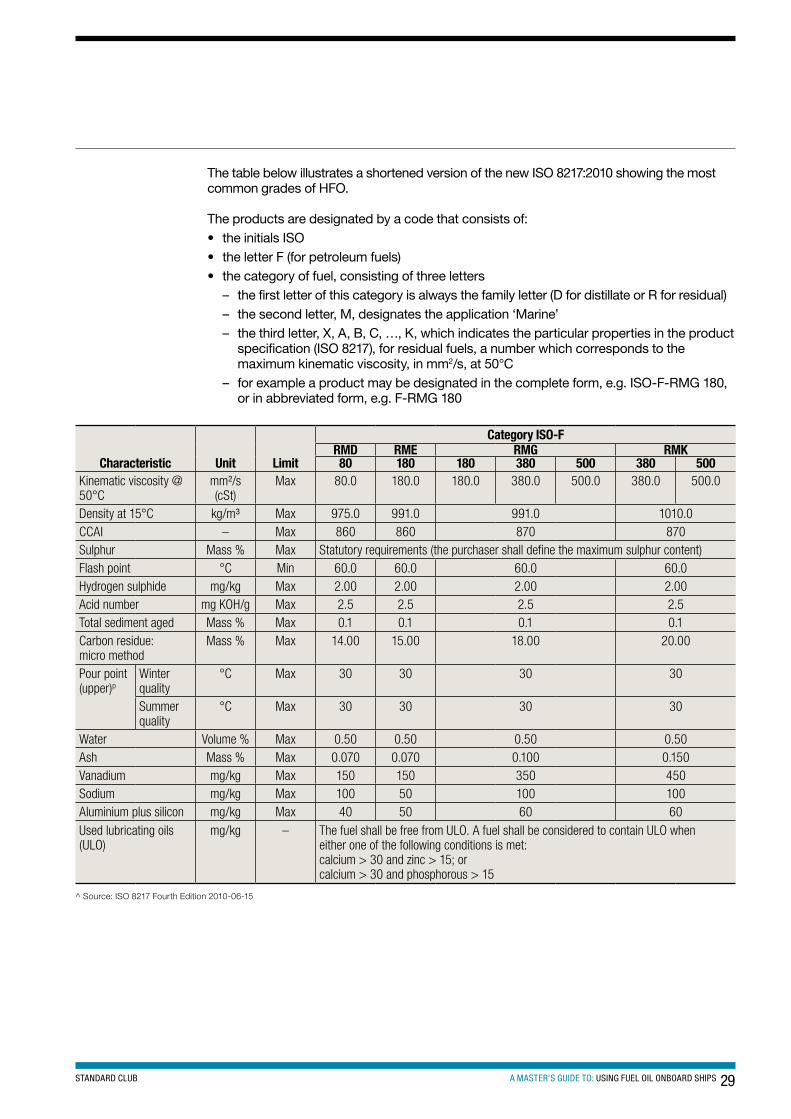
The table below illustrates a shortened version of the new ISO 8217:2010 showing the most common grades of HFO.
The products are designated by a code that consists of:• the initials ISO• the letter F (for petroleum fuels)• the category of fuel, consisting of three letters
– the first letter of this category is always the family letter (D for distillate or R for residual) – the second letter, M, designates the application ‘Marine’ – the third letter, X, A, B, C, …, K, which indicates the particular properties in the product
specification (ISO 8217), for residual fuels, a number which corresponds to the maximum kinematic viscosity, in mm2/s, at 50°C
– for example a product may be designated in the complete form, e.g. ISO-F-RMG 180, or in abbreviated form, e.g. F-RMG 180
^ Source: ISO 8217 Fourth Edition 2010-06-15
characteristic Unit Limit
category Iso-FRMD RMe RMG RMK80 180 180 380 500 380 500
Kinematic viscosity @ 50°C
mm²/s (cSt)
Max 80.0 180.0 180.0 380.0 500.0 380.0 500.0
Density at 15°C kg/m³ Max 975.0 991.0 991.0 1010.0CCAI – Max 860 860 870 870Sulphur Mass % Max Statutory requirements (the purchaser shall define the maximum sulphur content)Flash point °C Min 60.0 60.0 60.0 60.0Hydrogen sulphide mg/kg Max 2.00 2.00 2.00 2.00Acid number mg KOH/g Max 2.5 2.5 2.5 2.5Total sediment aged Mass % Max 0.1 0.1 0.1 0.1Carbon residue: micro method
Mass % Max 14.00 15.00 18.00 20.00
Pour point (upper)p
Winter quality
°C Max 30 30 30 30
Summer quality
°C Max 30 30 30 30
Water Volume % Max 0.50 0.50 0.50 0.50Ash Mass % Max 0.070 0.070 0.100 0.150Vanadium mg/kg Max 150 150 350 450Sodium mg/kg Max 100 50 100 100Aluminium plus silicon mg/kg Max 40 50 60 60Used lubricating oils (ULO)
mg/kg – The fuel shall be free from ULO. A fuel shall be considered to contain ULO when either one of the following conditions is met: calcium > 30 and zinc > 15; orcalcium > 30 and phosphorous > 15
30 STANDARD CLUB A MASTER’S GUIDE TO: USING FUEL OIL ONBOARD SHIPS
BUnKeRInG
Purchasers shall ensure that this pour point is suitable for the equipment onboard, especially if the ship operates in cold climates
Changes to the residual fuels (six categories) from the 2005 third edition include the following:• RMA6 10 has been added (not shown in the table above)• RMG and RMK have been expanded to include additional viscosity grades• RMF and RMH categories have been removed• the addition of the Calculated Carbon Aromaticity Index (CCAI) and specifications for the
following characteristics: hydrogen sulphide7, acid number and sodium content• sulphur limits have not been tabulated, as these are controlled by statutory requirements• potential Total Sediment (TSP) has been assigned as the reference test method.• accelerated Total Sediment (TSA) has been added as an alternative test method• ash limit values have been reduced for many of the categories• vanadium limit values have been reduced, with the exceptions of those for RMB 30
where the limit value is unchanged and for RMG 380 where the limit value has been slightly increased
• aluminium-plus-silicon limit values have been reduced• the criteria for assessing whether a fuel contains used lubricating oil have been amended
It should be noted that the ISO 8217 standard is occasionally reviewed by International Maritime Organization (IMO) and therefore all concerned should check that minimum and maximum limits are from the latest edition.
Bio-derived products and Fatty Acid Methyl Esters (FAMEs)If you drive a diesel vehicle in the European Union you may or may not be surprised to know that they are burning a blend of petroleum diesel and up to 7% bio-diesel, brought about by EU legislation to reduce emissions and dependence on hydrocarbon fuels. USA, Australia and Brazil are among countries which have mandated the use of bio-derived products in their diesel and other petroleum based fuels. So does this mean that the marine industry will follow the same path?
What is meant by ‘bio-diesel’? This is a fuel made for diesel engines from a wide range of vegetable oils or animal fats. These oils and fats are put through a process enabling the product to be used in diesel engines. When expressed in chemical terms, they are known as Fatty Acid Methyl Esters (FAME), the specification for which is in the standard EN 14214. It is not a new discovery; in fact the first diesel engine (1893) ran on peanut oil.
Acknowledging that there are potential benefits of reduced emissions, when using FAME, getting it to the engine in a satisfactory condition is not so simple. Characteristically, FAME has poor oxidation and thermal stability; stable storage duration may be as little as four weeks, although with the addition of additives, this may be extended by 6–12 months, perhaps longer. However, for most ships this would be considered too short a period.
It is worth noting that the acid decomposition products of FAME are suspected of causing damage to fuel pumps, injectors and piston rings. The ISO 8217:2010 standard now includes an acid test. Results of this test should be no greater than 2.5 mg KOH/g. This is commonly termed the acid number and is expressed in milligrams of potassium hydroxide per gram.
6 RMA, RMG and RMK is a fuel grade specification under ISO 8217, the international marine fuel standard.7 The inclusion in the International Standard of an H2S in liquid phase limit of 2.00 mg/kg in the fuel directly
reduces the risk of H2S vapour exposure. However, it is critical that ship owners and operators continue to maintain appropriate safety processes and procedures designed to protect the crew and others (e.g. surveyors), who can be exposed to H2S vapour.
31A MASTER’S GUIDE TO: USING FUEL OIL ONBOARD SHIPSSTANDARD CLUB
At present there are no industry guidelines to address the complications related to the use of FAME products as a fuel on a ship. It should be noted however that the current ISO 8217: 2010 marine fuel standard does not allow any bio-derived products to be blended into marine distillate or residual fuels, (Clause 5.4 of ISO 8217:2010).
Notwithstanding that FAME has good ignition, lubricity properties and perceived environmental benefits, there are potentially specific complications with respect to storage and handling in a marine environment such as:• a tendency to oxidation and long-term storage issues• affinity to water and risk of microbial growth• degraded low-temperature flow properties• FAME material deposition on exposed surfaces, including filter elements
The International Standard specifically refers to petroleum-derived materials, thereby excluding any bio-derived materials. However, the practice of blending FAME into automotive diesel and heating oils makes it almost inevitable, under current supply logistics, that some distillates supplied in the marine market can contain FAME. Even some residual fuels can contain FAME as a result of refinery processes, or blending a distillate cutterstock containing FAME.
Precautionary approachThere is no generalised experience with respect to the storage, handling, treatment and service performance of FAME within the maritime industry. It is necessary to adopt the precautionary principle to address any safety concerns in this area of using either blends of FAME/petroleum products or 100% FAME. Furthermore, there are the issues as to the potential effects of FAME products on the range of marine engines and other equipment (oily water separators or overboard discharge monitors (ODM)). Therefore, this International Standard limits the FAME content to a ‘de minimis’8 level.
To date, determining a ‘de minimis’ level is not straightforward given that:• a wide range of FAME products from different sources is available in the market• varying levels of contamination can be present through the use of common equipment
or pipelines in refineries, fuel terminals and other supply facilities• a wide range of analytical techniques is used to detect these FAME products and
associated by-products with no standardised approach• in most cases, sufficient data are not yet available on the effects of FAME products on
marine fuel systems
For the purpose of the International Standard:• in the case of distillate fuels (DMX, DMA, DMZ and DMB when clear and bright), it is
recommended that ‘de minimis’ be taken as not exceeding approximately 0.1% volume when determined in accordance with EN 14078
• in the case of DMB when it is not clear and bright and all categories of residual fuels, ‘de minimis’ cannot be expressed in numerical terms since no test method with a formal precision statement is currently available. Thus, it should be treated as contamination from the supply chain system
8 So small or minimal in difference that it does not matter or the law does not take it into consideration.
32 STANDARD CLUB A MASTER’S GUIDE TO: USING FUEL OIL ONBOARD SHIPS
Fuel producers and suppliers should ensure that adequate controls are in place so that the resultant fuel, as delivered, is compliant with the requirements of Clause 5 of the International Standard 8217:2010.
Catalytic finesHeavy cycle oil is used worldwide in complex refining as a blending component for heavy fuel. Mechanically damaged catalyst particles (aluminium silicate) cannot be removed completely in a cost-effective way, and are found in blended heavy fuel. Correct fuel purifying and filtration onboard ships have a removal efficiency of approximately 80 to 90% for catalytic fines. In order to avoid abrasive wear of fuel pumps, injectors and cylinder liners, the maximum limit for aluminium and silicon defined in ISO 8217: 2010 is 40–60 mg/kg depending on the viscosity.
There are, however, still reported problems with catalytic fines especially in low sulphur fuels. How can we explain this?
More efficient methods during the refinery process have led to the size of the catalytic fines reducing. This creates a problem for the shipboard purifier to remove them effectively, as the purifier relies on gravity for separation of the fines. Consequently some of the small fines are passing through to engines and still causing damage.
SludgeSludge is a contaminant that results from the handling, mixing, blending, and pumping of heavy fuel while stored at, and after it leaves, the refinery. Storage tanks, heavy fuel pipe lines, and barging can all contribute to the build-up of sludge. Water contamination of a high asphaltene fuel oil can produce an emulsion during fuel handling which can contain more than 50% water. Shipboard transfer pumps can frequently provide the necessary energy to produce emulsified sludges during normal fuel transfers. These emulsified sludges can cause rapid fouling and shutdown of centrifugal purifiers, clogging of strainers and filters in the fuel oil system and rapid fouling if burned in the engine.
FibresFibre contamination can cause significant problems in fuel handling onboard ships. This type of contamination usually occurs during transport and storage. Fibres can plug suction strainers protecting pumps, within minutes of initial operation. Whereas cleaning strainers is not a difficult task, the frequency of cleaning and the need for round-the-clock attention generally create problems with the allocation of manpower. A centrifuge normally is ineffective in removing oil soaked fibres because they have the same density as the oil being purified. Hence, downstream manual or auto-strainers and fine filters can be expected to clog quickly, and continue to clog frequently until the entire amount of a fibre contaminated fuel has been consumed or removed.
BUnKeRInG
33A MASTER’S GUIDE TO: USING FUEL OIL ONBOARD SHIPSSTANDARD CLUB
Oxidation productsThis form of contamination is the result of the marine residual fuel ageing, either before or after it is bunkered. Residual fuels are not stable for long periods at elevated storage temperatures. The time from the refinery to use onboard ideally should be less than three months. It is anticipated that future residual fuels resulting from more intense secondary processing will be even less stable. Heated heavy fuels, stored in uncoated steel tanks and exposed to air (oxygen) will oxidise and polymerise with time. The resultant sludges, gums and resins will initially form in solution and then collect and settle or adhere to the tank’s surfaces. Also, as heavy fuels age, their shipboard conditioning and treatment become more difficult. In the extreme, the diesel engine’s combustion process can deteriorate, causing increased fouling deposits and corrosion, as a result of burning such partially oxidised older fuel oils. Generally, residual fuel oils should not be bunkered or utilised as ballast, trim, or held in reserve for extended periods. The oldest on spec fuel on the ship should be burned first to prevent any heavy fuel oil from ageing beyond three months from its bunkering date.
Microbial contaminationMicrobial contamination usually occurs with jacket water systems, diesel fuels and lubricating oils onboard ship. However, there have been instances where HFO and IFO have been contaminated.
MicrobesMicrobes in fuel are bacteria, yeasts or moulds. They are normally of the hydrocarbon degrading and corrosive species.
1. they need water, nutrients and warmth to grow2. microbes live in the water phase, but feed off nutrients in the fuel phase3. microbes dislike agitation, preferring a dormant fuel system
Sources of microbial contamination1. imported infested hydrocarbons from refineries or bunker barges2. residues remaining onboard from previous bunker barge operation3. sea water
There will always be a risk of contamination to shipboard residual fuel from one of the following:1. load port contamination of storage tanks2. load port delivery piping3. cargo tanks of the ship4. pump room of the ship5. sea water ingress
34 STANDARD CLUB A MASTER’S GUIDE TO: USING FUEL OIL ONBOARD SHIPS
BUnKeRInG
The latest microbe species have spawned new types of bacteria in fuels, which produce sticky polysaccharide polymers very similar to cling-film. This clogs filters by trapping particles.
Microbial attack over time will degrade the fuel, reducing its calorific value. Waste products such as hydrogen sulphide will cause the cloud point and thermal stability of the fuel to be affected and a stable water haze will be created. Eventually the fuel will fail specification tests for water separation.
PreventionThe first point to note is that low numbers of microbes will ALWAYS find their way into a fuel system. If they reproduce slowly they will not accumulate. If a large infestation occurs the potential for trouble will be established. Physical prevention Water is the key ingredient to tackle.
1. assess fuel tank drainage systems2. implement an effective water drainage programme as a part of normal
watchkeeping routines3. implement quarterly cleaning and chemical disinfection of fuel systems, purifiers,
filters and coalescers4. isolate service tanks against suspect fuel if possible5. implement a fuel tank inspection schedule for bio-film and corrosion damage6. eradicate microbial levels on a regular basis7. monitor fuel suppliers’ quality8. send off quarterly samples of the HFO service and settling tank for laboratory analysis
DecontaminationMicrobes do not die naturally. They must be killed or removed, and all of the following are possible approaches:1. settling: microbes are denser than fuel and will settle at the bottom of a tank2. centrifugal: microbes subjected to centrifugal forces will separate out3. heat: microbes exposed to heat in excess of 70°C will be killed4. pumping out the tank ashore and hand-cleaning the tank’s surface using a
manufacturer’s recommended disinfectant
Identifying microbial attackRoutine sampling and microbiological testing is the only effective way to detect and identify the presence and activity of microbes.
Ready-to-use and onboard cargo fuel should be tested weekly. Water phase samples from storage tanks or engine room tanks should be taken and if infected fuel is detected, action should be taken.
Professional assistance should be sought if microbial contamination develops and the use of biocides is necessary as part of the treatment process.
35A MASTER’S GUIDE TO: USING FUEL OIL ONBOARD SHIPSSTANDARD CLUB
Fuel additivesBiocides
• they should be chemically compatible with the fuel, the machinery and the system components
• moderately contaminated fuels can be used after dosing, providing the biocide has been circulated fully
• severely contaminated fuels will have sediment after dosing with biocides. These deposits and sludges must be removed by physical decontamination to prevent blocked fuel systems
• seek advice from the bunker fuel analysing company and/or the ship’s chemicals supplier
Bunker system maintenanceBunker lines are to be pressure tested annually under static liquid pressure of at least 1.5 times the maximum allowable working pressure. It is recommended to stencil the pressure test rating and date of test on the bunker pipeline.
Overflow and high level alarms (where fitted) are to be tested and recorded as part of the ship’s planned maintenance alarm testing routines.
Bunker valves are to be checked for correct operation, and glands inspected and lubricated to ensure that they are free to operate. This should be incorporated into the ship’s planned maintenance system. Remotely operated valves should also be incorporated into the planned maintenance routines to ensure that they are opening effectively, actuators are not leaking and micro-switches are not loose or defective.
36 STANDARD CLUB A MASTER’S GUIDE TO: USING FUEL OIL ONBOARD SHIPS
Charterparty clausesWhen a ship is on voyage charter, the owner remains responsible for the provision of bunkers unless otherwise agreed. However, where the ship is on time charter then it is the charterers who are responsible for providing and paying for the fuel. Owners must be vigilant when negotiating the wording of charterparty clauses relating to bunker fuel supply.
Matters can become complicated when a charterer is contractually positioned between the bunker supplier and the shipowner. If there is a complaint about fuel quality, there may be proceedings between the charterer (as fuel purchaser) and bunkers supplier, or between the shipowner and charterer under the charterparty. The shipowner may also proceed against the bunker supplier.
The standard types of charterparties contain clauses regarding bunkers which should address the following:• quantity of bunkers on delivery/redelivery• safety of the place and location where the ship bunkers• ownership of the bunkers at the end of the charter period• quality• charterer’s
Note that the ship’s description or particulars which is often attached to the charterparty must be accurate. This includes the quantity of bunker space available at say 90% capacity.
QuantityMany charterparties contain a clause setting out the quantity or approximate quantity of bunkers that should be onboard the ship at the time of delivery/redelivery, + or – a margin. This quantity is assessed at the time of delivery or redelivery by either an off hire/on hire survey or by using ship figures.
Safety of the place where the ship bunkersMost charterparties contain a clause that the ship is to be employed in lawful trades between safe ports. A safe port is normally termed as follows:
“A port will not be safe unless, in the relevant period of time, the ship can reach it, use it and return from it without, in the absence of some abnormal occurrence, being exposed to danger which cannot be avoided by good navigation and seamanship.”
The issue of a safe place for bunkering can be at times problematical. Often bunkers can only be taken in specified locations authorised by the port. These locations may not be suitable because of congestion or weather exposure, for example. The master should be firm in only accepting to arrange bunkers in a safe location.
Ownership of the bunkers at the end of charter periodAll time charterparty forms will provide that charterers are to take over and pay for the fuel onboard the ship at the time of delivery and owners are to do likewise at the time of redelivery. Typical wording is as follows:
“Charterers shall accept and pay for all the bunkers onboard at the time of delivery, and owners shall on redelivery (whether it occurs at the end of the charter period or on the earlier termination of the charter) accept and pay for all bunkers remaining onboard.”
DocUMentAtIon04
37A MASTER’S GUIDE TO: USING FUEL OIL ONBOARD SHIPSSTANDARD CLUB
QualityThis is probably the most common area for complaint. A typical wording is as follows:
“The charterers shall supply bunkers of a quality suitable for burning in the ship’s engines and auxiliaries and which conform to the ISO 8217 4th Edition.
The owners reserve their right to make a claim against the charterers for any damage to the main engines or the auxiliaries caused by the use of unsuitable fuels or fuels not complying with the ISO 8217 4th Edition standards or which otherwise prove unsuitable for burning in the ship’s engines or auxiliaries. The owners shall not be held responsible for any reduction in the ship’s speed performance and/or increased bunker consumption, nor for any time lost and other consequences.”
Another typical clause relates to fuel oil sampling and analysis:
“Three samples of all fuel shall be taken during delivery, sealed and signed by suppliers, Chief Engineer and Charterers’ agent, each of whom should retain one sample. If any claim should arise in respect of the quality or specification of the fuel supplied, the Owners and Charterers agree to have samples of the fuel analysed by a mutually agreed analyst.”
The Baltic and International Maritime Council (BIMCO) provide guidance on bunker quality clauses including bunker fuel sulphur content clauses.
CharterersA charterer will also want to ensure that the bunkers remaining on board after delivery conform to the ISO 8217 4th Edition fuel specifications. This should be included in the charterparty, otherwise the charterer may be held liable for any subsequent damages that arise from the use of existing bunkers on board.
Charterers should also consider that fuel oil analysis is carried out on residual fuels bunkered which should not be used until a positive fuel oil analysis has been received.
SummaryA bunker quality control clause should be drafted carefully and take into account:• bunker fuel specifications for both residual fuel oils and diesel fuels• stipulations on delivery receipts and number of samples to be taken, sealing procedure
and time of retention• owner’s reservation of right to claim for damages caused by the use of unsuitable fuel
oil supplied
Refer to BIMCO Bunker Quality Control Clause for Time Chartering for example.
Ships trading in areas where bunker grades are difficult to obtain require careful consideration as to the bunker clause. In many outlying parts where fuels are blended on the bunker barge, the quality may be suspect. As previously mentioned, fuel oils should not be mixed with existing bunkers onboard and not used until an acceptable fuel oil analysis report has been received.

38 STANDARD CLUB A MASTER’S GUIDE TO: USING FUEL OIL ONBOARD SHIPS
DocUMentAtIon
Bunker Supply ContractsThe supply of bunkers is agreed between the supplier and the ship operator on a separate contract to the charter party. The ship operator (charterer or owner) will enter into contractual relations with the supplier usually based on the supplier’s standard terms. BIMCO has published standard conditions for the supply of bunkers. These contracts however have gained little traction within the industry. Nonetheless they may act as an appropriate guide for the bunker purchaser during negotiations.
Caution is to be exercised in accepting standard terms during negotiations of bunker supply contracts as they are usually particularly onerous on the purchaser. These terms will commonly contain provisions relating to limitation of liability, the time within which claims must be brought against the supplier and the manner in which sampling of the bunkers take place.
1. Limitation of liabilityStandard terms and conditions will often aim to minimise the liability that can be attributed to the bunker supplier for example: “In no event shall Seller’s liability for any claim or claims arising under this contract related to a particular nomination exceed in the aggregate the sum of $300,000.”
2. Time barStandard terms and conditions nearly always stipulate a time limit within which claims should be brought. These time bars should pose no real problem in questions of quantity as this should be ascertainable following bunkering operations. However, this is not the case in quality disputes where off specification bunkers may affect the performance of the engine over a longer period of time.
3. Manner in which sampling of bunkers takes placeOne of the most important aspects of the bunkering procedure is sampling. As may be expected sampling is a highly contentious subject often leading to disputes between the parties involved. On the operator’s side, there is a clear preference for sampling to take place at the receiving ship’s bunker manifold, which it is felt gives the least possibility of tampering. Bunker suppliers on the other hand will almost always insist upon barge samples.
Bunkering instructionsThe company safety management system must include instructions and procedures for bunkering. Risk assessments must be carried out prior to bunkering. The risk assessment should be reviewed regularly as considered fit by the company. The ship’s chief engineer should have posted the bunkering instructions at the bunker station for all parties involved to read. It is usual for these instructions to be included in the bunker plan. Good practice should ensure that these instructions are read and fully understood before any bunkering commences.
Oil Record BookAn Oil Record Book (ORB) Part I must be carried on board every oil tanker of 150 gross tons and above and every other ship of 400 gross tons and above to record relevant machinery space operations. In addition, oil tankers of 150 gross tons and above shall carry an Oil Record Book Part II to record cargo and ballast operations.
Owners, masters and officers are reminded that, in addition to statutory requirements concerning maintenance of an ORB, this record is a valuable means of providing proof that the ship has complied with anti-pollution regulations.
In the past the club’s surveyors have noted that this subject does not seem to be either well defined or fully understood by ships’ officers or MARPOL inspectors. IMO guidance on entries in the ORB has been somewhat ambiguous, although from January 2007 this was changed.
39A MASTER’S GUIDE TO: USING FUEL OIL ONBOARD SHIPSSTANDARD CLUB
Clear guidance should be given to ship’s personnel on how to complete correctly the ORB.
The club suggests that a standard format for entries is adopted by the owner’s ships to try to avoid the possibility of fines from Port State Control (PSC) or others for incorrect record keeping.
A comprehensive listing of machinery space items to be recorded in the ORB, is included in Appendix III of Annex 1 to MARPOL 73/78 as amended.
All entries in the ORB must be in ink. Writing in pencil in any log record should be avoided, and all entries should be made at the time of the operation to avoid mistakes.
When making entries in the ORB, the date, operational letter code and item number should be inserted in the appropriate columns and the required particulars shall be recorded chronologically in the blank spaces. The entries in the ORB, for ships holding an IOPP Certificate, should be at least in English, French or Spanish. Where entries in the official language of the state whose flag the ship is entitled to fly are also used, this shall prevail in case of a dispute or discrepancy. The ORB should be readily available for inspection at all reasonable times and, except in the case of unmanned ships under tow, should be kept on the ship. It should be preserved for three years after the last entry has been made.
Each completed operation should be signed for and dated by the officer or officers in charge and each completed page shall be countersigned by the master of the ship.
The ORB contains many references to oil quantity. The limited accuracy of tank measurement devices, temperature variations, and clingage9 will affect the accuracy of these readings. The entries in the ORB should be considered accordingly.
The areas of most concern to the club are the entries required when:• related to oil residue (sludge and other residues) retained onboard the ship • transferring or disposing of oil residues• operating the oily water separator, when non-automatic disposal methods are used• transferring and collecting bilge water to the bilge tanks and any oil residue (sludge)
content of the bilges• related to other operations required under Section (I), that is removal of any bilge or
oily water separator piping or valves for maintenance purposes
The chief engineer is responsible for ensuring that the ORB is correctly maintained. Although some companies may delegate this to the second or first engineer, the responsibility should still lie with the chief engineer. The master however should regularly check the ORB to see that it is correct. The master is required to sign the ORB after each page is completed but a visual check before every port entry is recommended. This important document, if not accurately completed, can lead to the ship’s master and/or chief engineer being fined or detained.
It should be noted that all entries in the ORB must be wholly true and accurate. Fines for falsifying ORB entries can be greater than $2m and result in imprisonment.
9 Oil adhering to the wall of a tank after the tank has been pumped and drained.
40 STANDARD CLUB A MASTER’S GUIDE TO: USING FUEL OIL ONBOARD SHIPS
DocUMentAtIon
Bunker receiptsClause 18 of MARPOL Annex VI requires that all fuel oil received by a ship must be accompanied by a bunker delivery receipt.
The bunker delivery receipt should be kept on the ship and readily available for inspection at all reasonable times. It should be retained for three years after the fuel has been delivered.
Clause 18 of MARPOL Annex VI also requires that the bunker delivery receipt must be accompanied by a representative sample of fuel oil sealed and signed by the supplier.
The bunker delivery receipt is to be signed by the bunker barge master and the chief engineer or master of the ship receiving fuel oil. It is normally stamped with the official stamp of the ship and/or barge.
Because the chief engineer normally does not have access to an accurate, laboratory-determined fuel density figure (this will be ascertained by laboratory analysis of the bunker sample or by use of certified onboard test equipment), the bunker delivery receipt should be completed using only figures for the volume of fuel oil loaded. The chief engineer should sign only documentation stating “for volume at observed temperature only” as there can be no certainty of any weight figures for the fuel loaded.
If fuel oil is taken in a country that has not ratified MARPOL Annex VI, the supplier is not required to issue a bunker delivery receipt that complies with MARPOL requirements. However, the ship may require suitable documentation to satisfy port state control officers at subsequent ports.
The recommended procedure if such a situation arises is that the master should notify the port state authorities at the port where the fuel oil was taken, and the ship’s flag state, and keep a copy of such notification on board to produce to officials at subsequent port state inspections.
A bunker delivery receipt and representative fuel sample should be obtained whenever possible.
Letters of protestIt is important that, in the event of a bunker quantity dispute arising, the master of the receiving ship issues a letter of protest as quickly as possible. Such a letter of protest should include but not be limited to the following points:• date and time fuel oil was loaded• name of ship receiving the fuel oil• volume shortage• grade of fuel oil loaded (or thought to have been loaded)• percentage shortage in relation to the order• name of bunker supplier• name of bunker barge or shore facility• bunker delivery receipt reference number
41A MASTER’S GUIDE TO: USING FUEL OIL ONBOARD SHIPSSTANDARD CLUB
The letter of protest should be signed by the master and/or the chief engineer. It should be directed to the barge master or shore representative and copied to the following interested parties:• shipowner or manager • charterer (if time charter fuel oil) • organisation or laboratory analysing the fuel oil • bunker supplier • bunker broker
The letter of protest should also be signed, if possible by the barge master or shore representative and properly stamped with the ship and barge official stamps.
Many bunker suppliers incorporate very short time bars in their contracts and it is vital that any protest is registered within the specified time frame. It may be very difficult to determine fuel oil quality within the time bars, which can be as short as 24 hours.
Fuel oil analysis reportsThe benefit of a complete and accurate shoreside analysis can be summarised as follows: 1. confirmation that bunkers as received meet purchase specifications (or do not meet
specs, as the case may be)2. provides warning of contaminant levels, incompatibility, excessive water content, etc3. enables engineers to adopt suitable strategies for proper utilisation of the fuel4. provides permanent independent third-party report (analysis) of fuel oil received and
enables owner to claim against bunker supplier in case of failure to meet purchase specifications or in case of delivery of unmarketable product
5. shoreside laboratory will normally alert owner to any unusual or potentially damaging characteristics or fuel oil and will suggest countermeasure strategies
The single most important constraint in this process is time. It is highly desirable to have the results of the shoreside analysis available to the owner (and, of course, the ship’s engineer) before the fuel is to be used and the damage done. Normal practice requires that new bunkers are segregated from existing bunkers to the greatest extent possible.
An efficient shoreside laboratory should be able to complete a sample analysis and transmit advice of results within 24 hours of receiving the sample.
The proper management of the dispatch and routing of the sample is of great importance to avoid delay in obtaining the results.
In general, it is preferable to use one shoreside laboratory using known and accepted analytical techniques rather than a variety of laboratories around the world. This will avoid slight anomalies in the sample results by using different analysis companies. Select a company with which you are happy and use it whenever possible.
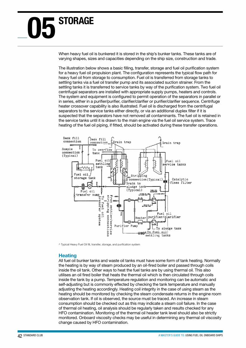
42 STANDARD CLUB A MASTER’S GUIDE TO: USING FUEL OIL ONBOARD SHIPS
When heavy fuel oil is bunkered it is stored in the ship’s bunker tanks. These tanks are of varying shapes, sizes and capacities depending on the ship size, construction and trade.
The illustration below shows a basic filling, transfer, storage and fuel oil purification system for a heavy fuel oil propulsion plant. The configuration represents the typical flow path for heavy fuel oil from storage to consumption. Fuel oil is transferred from storage tanks to settling tanks via a fuel oil transfer pump and its associated suction strainer. From the settling tanks it is transferred to service tanks by way of the purification system. Two fuel oil centrifugal separators are installed with appropriate supply pumps, heaters and controls. The system and equipment is configured to permit operation of the separators in parallel or in series, either in a purifier/purifier, clarifier/clarifier or purifier/clarifier sequence. Centrifuge heater crossover capability is also illustrated. Fuel oil is discharged from the centrifugal separators to the service tanks either directly, or via an additional duplex filter if it is suspected that the separators have not removed all contaminants. The fuel oil is retained in the service tanks until it is drawn to the main engine via the fuel oil service system. Trace heating of the fuel oil piping, if fitted, should be activated during these transfer operations.
^ Typical Heavy Fuel Oil fill, transfer, storage, and purification system
HeatingAll fuel oil bunker tanks and waste oil tanks must have some form of tank heating. Normally the heating is by way of steam produced by an oil-fired boiler and passed through coils inside the oil tank. Other ways to heat the fuel tanks are by using thermal oil. This also utilises an oil fired boiler that heats the thermal oil which is then circulated through coils inside the tank by a pump. Temperature regulation and monitoring can be automatic and self-adjusting but is commonly effected by checking the tank temperature and manually adjusting the heating accordingly. Heating coil integrity in the case of using steam as the heating should be monitored by checking the steam condensate returns in the engine room observation tank. If oil is observed, the source must be traced. An increase in steam consumption should be checked out as this may indicate a steam coil failure. In the case of thermal oil heating, oil analysis should be regularly taken and results checked for any HFO contamination. Monitoring of the thermal oil header tank level should also be strictly monitored. Onboard viscosity checks may be useful in determining any thermal oil viscosity change caused by HFO contamination.
stoRAGe05
43A MASTER’S GUIDE TO: USING FUEL OIL ONBOARD SHIPSSTANDARD CLUB
Bunker capacityThe bunkering capacity of ships varies from ship to ship. In fact not even sister ships may have the same bunker tank capacity as a result of small design changes and tank fabrication discrepancies during building.
The maximum allowable filling capacity of a bunker tank varies from one company to another and should be documented in the company’s safety management system. Normally, the maximum is in the range of 85 to 90% although this may vary from ship to ship. Remember that allowance for fuel expansion from bunker tank heating should always be factored into the initial filling level. The 90% capacity figure should include an allowance for heat expansion. Overlooking this has in many instances led to heavy fuel oil tank overflows.
Settling tanksSettling tanks have several important functions in the proper treatment of heavy fuel oil. They provide a settling function for suspended water and solids, a heating function, a de-aeration function, and a thermal stabilising function.
Ships’ settling tanks are designed to accept fuel oils with a 60°C minimum flash-point. The ‘two settling tank’ concept is the most common arrangement fitted to new ships. One settling tank may contain low sulphur fuel oil and the other the high sulphur fuel for use outside sulphur emission-controlled areas. A three-way change over valve may be fitted to ensure that the fuel change-over is made as trouble free as possible. Engineers should always follow the company’s fuel change-over procedures. Please refer to the ‘Fuel changeover procedure basic guidelines’ section below.
As soon as a settling tank is filled, it is normally heated to approximately 72°C, or 6°C below the flash-point, whichever is lower.
From a safety standpoint, fuel oils must never be heated in ships’ bunker tanks at or above the fuel’s flash-point. The tanks should be insulated where possible to reduce heat loss. It is important to shut off the settling tank heat source once its contents are up to temperature, because continuous heating will produce thermal currents within the tank which interfere with the settling process. Ships have high tank temperature alarms and may also have automatic regulators.
Because of constant heat loss from a settling tank, it may be necessary to reactivate the tank heating system periodically to maintain its contents at 60°C or better. Settling tanks should have bottom drains for water and sludge stripping. Water and sludge should be removed on a regular basis by means of these drains as part of a normal watchkeeping routine. During periods of heavy weather it is necessary to drain fuel storage tanks more regularly than usual. Ships’ engines have stopped when this has not been carried out in rough weather, and this can be one of the worst situations for an engine failure.
SafetyHydrogen sulphide (H2S) may be present when heating fuel oils. It is a highly toxic gas and exposure to high vapour concentrations is extremely hazardous, and in some cases can be fatal. At very low concentrations, the gas has the characteristic smell of rotten eggs. At higher concentrations, it causes a loss of smell, headaches and dizziness and at very high concentrations is immediately fatal. H2S can be formed during the refining process and can evolve from the fuels in storage tanks, in product barges and bunker tanks. H2S can be present in both liquid and vapour phase and the degree and speed of partitioning between the liquid and vapour phase depend on several factors, for example the fuel chemistry, temperature, viscosity, level of agitation, storage time, heating applied, ambient conditions, tank shape, ullage and venting.
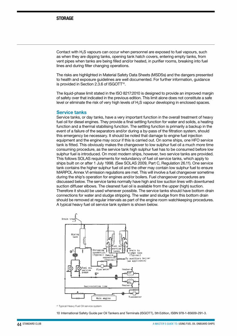
44 STANDARD CLUB A MASTER’S GUIDE TO: USING FUEL OIL ONBOARD SHIPS
Contact with H2S vapours can occur when personnel are exposed to fuel vapours, such as when they are dipping tanks, opening tank hatch covers, entering empty tanks, from vent pipes when tanks are being filled and/or heated, in purifier rooms, breaking into fuel lines and during filter changing operations.
The risks are highlighted in Material Safety Data Sheets (MSDSs) and the dangers presented to health and exposure guidelines are well documented. For further information, guidance is provided in Section 2.3.6 of ISGOTT10.
The liquid-phase limit stated in the ISO 8217:2010 is designed to provide an improved margin of safety over that indicated in the previous edition. This limit alone does not constitute a safe level or eliminate the risk of very high levels of H2S vapour developing in enclosed spaces.
Service tanksService tanks, or day tanks, have a very important function in the overall treatment of heavy fuel oil for diesel engines. They provide a final settling function for water and solids, a heating function and a thermal stabilising function. The settling function is primarily a backup in the event of a failure of the separators and/or during a by-pass of the filtration system, should this emergency be necessary. It should be noted that damage to engine fuel injection equipment and the engine may occur if this is carried out. On some ships, one HFO service tank is fitted. This obviously makes the changeover to low sulphur fuel oil a much more time consuming procedure, as the service tank high sulphur fuel has to be consumed before low sulphur fuel is introduced. On most modern ships, however, two service tanks are provided. This follows SOLAS requirements for redundancy of fuel oil service tanks, which apply to ships built on or after 1 July 1998. (See SOLAS 2009, Part C, Regulation 26.11). One service tank contains the higher sulphur fuel oil and the other may contain low sulphur fuel to ensure MARPOL Annex VI emission regulations are met. This will involve a fuel changeover sometime during the ship’s operation for engines and/or boilers. Fuel changeover procedures are discussed below. The service tanks normally have high and low suction lines with downturned suction diffuser elbows. The cleanest fuel oil is available from the upper (high) suction. Therefore it should be used whenever possible. The service tanks should have bottom drain connections for water and sludge stripping. The water and sludge from this bottom drain should be removed at regular intervals as part of the engine room watchkeeping procedures. A typical heavy fuel oil service tank system is shown below.
^ Typical Heavy Fuel Oil service system
10 International Safety Guide per Oil Tankers and Terminals (ISGOTT), 5th Edition, ISBN 978-1-85609-291-3.
stoRAGe
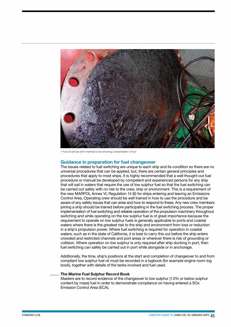
45A MASTER’S GUIDE TO: USING FUEL OIL ONBOARD SHIPSSTANDARD CLUB
^ Fuel oil service tank manhole cover showing contamination of fuel
Guidance in preparation for fuel changeoverThe issues related to fuel switching are unique to each ship and its condition so there are no universal procedures that can be applied, but, there are certain general principles and procedures that apply to most ships. It is highly recommended that a well thought-out fuel procedure or manual be developed by competent and experienced persons for any ship that will sail in waters that require the use of low sulphur fuel so that the fuel switching can be carried out safely with no risk to the crew, ship or environment. This is a requirement of the new MARPOL Annex VI, Regulation 14 (6) for ships entering and leaving an Emissions Control Area. Operating crew should be well trained in how to use the procedure and be aware of any safety issues that can arise and how to respond to these. Any new crew members joining a ship should be trained before participating in the fuel switching process. The proper implementation of fuel switching and reliable operation of the propulsion machinery throughout switching and while operating on the low sulphur fuel is of great importance because the requirement to operate on low sulphur fuels is generally applicable to ports and coastal waters where there is the greatest risk to the ship and environment from loss or reduction in a ship’s propulsion power. Where fuel switching is required for operation in coastal waters, such as in the state of California, it is best to carry this out before the ship enters crowded and restricted channels and port areas or wherever there is risk of grounding or collision. Where operation on low sulphur is only required after ship docking in port, then fuel switching can safely be carried out in port while alongside or in anchorage.
Additionally, the time, ship’s positions at the start and completion of changeover to and from compliant low sulphur fuel oil must be recorded in a logbook (for example engine room log book), together with details of the tanks involved and fuel used.
The Marine Fuel Sulphur Record BookMasters are to record evidence of the changeover to low sulphur (1.0% or below sulphur content by mass) fuel in order to demonstrate compliance on having entered a SOx Emission Control Area (ECA).
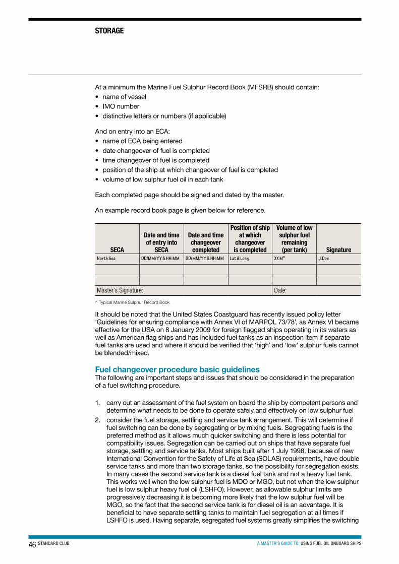
46 STANDARD CLUB A MASTER’S GUIDE TO: USING FUEL OIL ONBOARD SHIPS
stoRAGe
At a minimum the Marine Fuel Sulphur Record Book (MFSRB) should contain:• name of vessel• IMO number• distinctive letters or numbers (if applicable)
And on entry into an ECA:• name of ECA being entered• date changeover of fuel is completed• time changeover of fuel is completed• position of the ship at which changeover of fuel is completed• volume of low sulphur fuel oil in each tank
Each completed page should be signed and dated by the master.
An example record book page is given below for reference.
secA
Date and time of entry into
secA
Date and time changeover completed
Position of ship at which
changeover is completed
Volume of low sulphur fuel remaining (per tank) signature
North Sea DD/MM/YY & HH:MM DD/MM/YY & HH:MM Lat & Long XX M³ J.Doe
Master’s Signature: Date:
^ Typical Marine Sulphur Record Book
It should be noted that the United States Coastguard has recently issued policy letter ‘Guidelines for ensuring compliance with Annex VI of MARPOL 73/78’, as Annex VI became effective for the USA on 8 January 2009 for foreign flagged ships operating in its waters as well as American flag ships and has included fuel tanks as an inspection item if separate fuel tanks are used and where it should be verified that ‘high’ and ‘low’ sulphur fuels cannot be blended/mixed.
Fuel changeover procedure basic guidelinesThe following are important steps and issues that should be considered in the preparation of a fuel switching procedure.
1. carry out an assessment of the fuel system on board the ship by competent persons and determine what needs to be done to operate safely and effectively on low sulphur fuel
2. consider the fuel storage, settling and service tank arrangement. This will determine if fuel switching can be done by segregating or by mixing fuels. Segregating fuels is the preferred method as it allows much quicker switching and there is less potential for compatibility issues. Segregation can be carried out on ships that have separate fuel storage, settling and service tanks. Most ships built after 1 July 1998, because of new International Convention for the Safety of Life at Sea (SOLAS) requirements, have double service tanks and more than two storage tanks, so the possibility for segregation exists. In many cases the second service tank is a diesel fuel tank and not a heavy fuel tank. This works well when the low sulphur fuel is MDO or MGO, but not when the low sulphur fuel is low sulphur heavy fuel oil (LSHFO). However, as allowable sulphur limits are progressively decreasing it is becoming more likely that the low sulphur fuel will be MGO, so the fact that the second service tank is for diesel oil is an advantage. It is beneficial to have separate settling tanks to maintain fuel segregation at all times if LSHFO is used. Having separate, segregated fuel systems greatly simplifies the switching
47A MASTER’S GUIDE TO: USING FUEL OIL ONBOARD SHIPSSTANDARD CLUB
process and reduces the risks and crew effort as the switching is done by changing over the valve or valves that supply fuel to the fuel supply pumps for the engine or boiler. The switching verification process is much simpler with a segregated system, as the time for the valve changeover can be easily recorded and the time to flush the fuel system with the new fuel requires a few hours at most
3. a ship which does not have a tank arrangement that permits segregation of fuel beyond the storage tanks will have to develop procedures for fuel mixing. One way to do this is to reduce the level in the settling tank to about 20% of capacity before filling with the alternate fuel. With this arrangement, up to several days before entering an ECA may be needed to reduce the sulphur level in the mixed fuel to the required level. This can lead to high consumption of expensive low sulphur fuel, so consideration should be made to installing a segregated fuel system on any ship that regularly trades in areas where low sulphur fuel is required
4. before fuel switching, it is generally recommended to reduce ship power to the level indicated in the fuel switching procedure. Typically this is a power level of 30% to 70% Maximum Continuous Rating (MCR), depending on the specifics of the propulsion plant
5. avoiding thermal shock to the fuel system is one of the critical elements in a fuel switching procedure. Engine manufacturers normally offer guidance on the maximum allowed rate of temperature change in fuel systems, such as the commonly used rate of 2°C/minute. As an example of how to determine the time for fuel switching, if a ship is using HFO heated to about 150°C prior to the fuel injection pumps and switching to MGO at 40°C, the temperature difference is about 110°C. Under these conditions and considering a 2°C/minute permitted rate of change, the fuel switching process should take a minimum of 55 minutes to complete safely. Consider using longer than minimum time to prevent short-term rapid temperature changes during the process, which may not consist of a smooth, even temperature change. There are several difficulties that can occur in controlling the rate of temperature change: i. many ships carry out fuel switching by manually changing over a single three-way
valve. This immediately changes the fuel source and if the fuel switching is done at high power levels the fuel change is carried out in a relatively short period as the fuel circulates at a high rate through the mixing tank. Rapid change from HFO to MGO can lead to overheating the MGO, causing a rapid loss of viscosity and possible ‘gassing’ in the fuel system. Too rapid change from unheated MGO to HFO can lead to excessive cooling of the HFO and excessive viscosity at the fuel injectors, again causing loss of power and possible shutdown. If a single changeover valve is provided, it is recommended to carry out fuel switching with the engine at low power levels so the fuel change will occur gradually enough to remain within the temperature rate of change limits. If fuel switching is sought at higher power levels, the fuel switching system may have to be modified, including the possible installation of an automated fuel changeover system that changes the fuel in a timed and regulated manner. Such automated systems are now being offered by some engine makers and by fuel system equipment suppliers
ii. fuel heaters and pipe heat tracing should be turned off or on in a controlled manner during the fuel switching process. Most ships have a viscosity control system that controls the heat supply to the fuel preheaters located in the fuel supply system. This system will adjust the heat supply to the preheaters as the fuel viscosity changes during the fuel switch. However, when the change to low viscosity diesel oil is completed the heat supply needs to be turned off and any heat tracing should also be turned off when changing to low viscosity fuel
iii. when switching from heated HFO to MGO, engine components and fuel in the mixing tank will retain heat and as the still hot fuel mix becomes more pure MGO, there is real danger of ‘gassing’ occurring at the booster pumps, causing the engine to stop. Fuel temperature should be closely monitored during this process and components given sufficient time to cool before running on pure MGO. This is where fuel coolers can be of value
48 STANDARD CLUB A MASTER’S GUIDE TO: USING FUEL OIL ONBOARD SHIPS
6. Compatibility of the mixed fuels is an issue, as discussed earlier. During the fuel switching process, fuel filters, strainers and mixing tank should be carefully checked for evidence of clogging and excessive sludge forming. This is one reason that fuel switching is best done ahead of time in open waters clear of hazards.
7. If a fuel cooler is installed, turn it on and open the valves to the cooler carefully while closely monitoring the temperature of the fuel to prevent an excessive rate of cooling. When changing from cooled MGO to heated HFO, the cooler can usually be bypassed and shut off at the start of the process.
8. Purifiers should be adjusted to suit the new fuel. Make sure the suction and return pipes go to the correct tanks. If operating on MGO, a separate purifier may be in operation.
9. If there is fuel valve injector cooling on the engine, this may need to be turned off or on during fuel switching. After switching to MGO, fuel valve cooling may not be needed and if this is the case it should be turned off to prevent over-cooling of the fuel if the engine is to be operated for extended periods of time on MGO. If cooling was turned off, it should be turned on again when switching to heated HFO fuel. Consult with the engine manufacturer over this.
10. Monitor temperatures of the engine and its components to check that they are maintained at normal service temperatures. Adjust or re-set engine control equipment such as control valves, temperature sensors, viscosity controller etc, as needed, to account for the new fuel type, where this is not done automatically. As experience is gained with fuel switching there will be better understanding of what needs to be adjusted and monitored during the switching process and during sustained operation with MGO. During initial fuel switches, added vigilance is needed to spot potential problems before they become serious. Fuel switching procedures should be adjusted to account for identified problems.
11. Once the propulsion and generating plant are stabilised on the new fuel and all components are at normal service temperatures, it should be possible to bring back propulsion plant to normal power, and the vessel can proceed into restricted and port areas.
12. If sustained operation (more than five to seven days) on a fuel with a large difference in sulphur content is planned, engine manufacturers typically recommend that the cylinder oil type used in slow speed diesels be changed to the appropriate one for the sulphur content of the fuel being used.
Sludge and fuel oil leakage tanksHow sludge and fuel oil leakage occursSludge deposits in fuel tanks are caused by the presence of wax, sand, scale, asphaltenes, tars and water in the bunkered fuel. All fuel oil has sludge content but its release can be caused by mixing incompatible fuels, heating and purification.
The sludge created during the fuel processing by the purifiers is a perfectly normal phenomenon. After all, you do not want this to get into the service tanks. The sludge builds up in the purifier bowl and is normally automatically discharged after a set time (approximately two to four hours depending on fuel quality) to the sludge tank. There is usually a greater proportion of water discharged with the sludge but this also depends on the quality of the fuel oil being processed.
Fuel oil leakage occurs past engine fuel pumps, fuel injectors, fuel system booster pumps, filter drains, mixing units, heaters etc. When HFO has been transferred to the settling tank, the drain from this tank normally enters the fuel oil leakage tank.
StorageBoth sludge and fuel oil leakage are stored in dedicated heated tanks with pumping facilities either to the deck discharge connection or if fitted, to the incinerator.
stoRAGe
49A MASTER’S GUIDE TO: USING FUEL OIL ONBOARD SHIPSSTANDARD CLUB
Disposal of sludge and waste fuel oilSludge is disposed of ashore by using the ship’s dedicated sludge pump to pump from the sludge tank to a shore reception facility or barge via the sludge connection on deck.
Incineration is possible on some ships but is not recommended because the sludge is abrasive and not very combustible. It is after all a waste product from the fuel oil after purification. Some ships are fitted with a sludge de-watering unit whereby the sludge is processed and the water is removed and sent to the ship’s bilge water holding tank ready for disposal through the oily water separator. This type of system obviously keeps the need for pumping out the sludge tank ashore to a minimum as it is only the sludge that will be accumulated.
Fuel oil leakage is usually disposed of in the same way as sludge. Some companies prefer incineration as it is normally a mixture of diesel oil and heavy fuel oil leakages so may be of a reduced viscosity compared to the HFO onboard.
Whenever any fuel oil or sludge is disposed of, documented evidence must be kept in the oil record book. Refer above to the Documentation section: Oil Record Book.
Use of the oily water separatorA properly functioning oily water separator (OWS) is needed to ensure compliance with MARPOL. The OWS controls operational discharges overboard of waste water that accumulates in machinery spaces. An understanding of both the oil-water separating equipment and shipboard wastes that enter the bilge is necessary to manage properly onboard bilge water and oily waste.
In a typical ship, the main sources of contamination in bilge water and bilge holding tanks include but are not limited to the following:1. diesel engine intercooler condensation drains (clean water)2. sludge from decanting/bottom draining storage and sludge tanks due to lube oil and
fuel oil purification (oily water)3. fuel oil storage and settling tanks (oily water)4. lube oil and fuel oil filtration (oil)5. machinery leakages (fuel, oil and water)6. condensate from air compressors and compressed air systems7. diesel engine piston stuffing box leakages and piston underside blow-down
(slow-speed diesels only)8. boiler water/condensate drains (different from piston cooling water because these
include other types of chemicals such as solvents, causing different concerns)9. equipment and engine-room washing10. economiser water washing11. seawater and freshwater cooling (a potential source of biological contaminants)12. fire-fighting foam13. water treatment chemicals14. engine coolant15. grey water drains16. sanitary system leaks and overflows17. air conditioning and refrigeration condensate18. engine room cleaning
50 STANDARD CLUB A MASTER’S GUIDE TO: USING FUEL OIL ONBOARD SHIPS
The master, chief engineer and senior officers in the engine department should: • instruct users of OWS equipment and verify the standard achieved• verify that maintenance schedules are being followed• ensure that audits include operational tests and a reconciliation of records• ensure that scheduled tank sounding logs are maintained and signed for• keep records of verification of correct operation through testing at sea• ensure that onboard spares are adequate to meet demand• create a culture where complacency in operation and maintenance standards
is unacceptable
The master, chief engineer and senior officers in the engine department should:• ensure that all entries in the tank sounding log, ORB and incinerator logs are completed
promptly by the crew member who performed the task• ensure that each completed page of the ORB is examined and signed by the chief
engineer and/or the master• require signatures from those conducting overboard discharges and operational tests• ensure that ship familiarisation procedures verify that company environmental policy and
operability of equipment are understood and followed• require the status of pollution prevention equipment to be recorded in the handover notes
of the responsible engineer and the chief engineer• record the independent verification of the correct operation of the oil discharge
monitoring equipment• raise awareness of the need for an open chain of command and accurate record keeping
that can be substantiated with Port State Control
stoRAGe
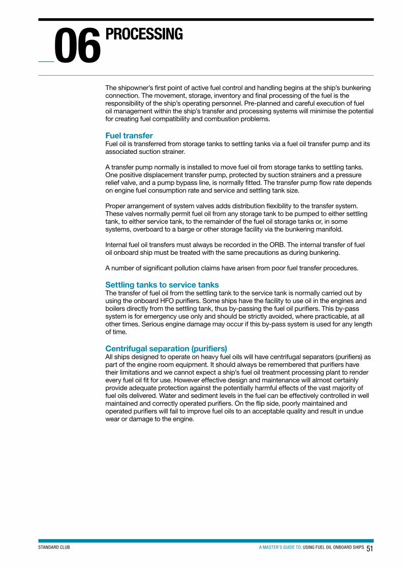
51A MASTER’S GUIDE TO: USING FUEL OIL ONBOARD SHIPSSTANDARD CLUB
The shipowner’s first point of active fuel control and handling begins at the ship’s bunkering connection. The movement, storage, inventory and final processing of the fuel is the responsibility of the ship’s operating personnel. Pre-planned and careful execution of fuel oil management within the ship’s transfer and processing systems will minimise the potential for creating fuel compatibility and combustion problems.
Fuel transferFuel oil is transferred from storage tanks to settling tanks via a fuel oil transfer pump and its associated suction strainer.
A transfer pump normally is installed to move fuel oil from storage tanks to settling tanks. One positive displacement transfer pump, protected by suction strainers and a pressure relief valve, and a pump bypass line, is normally fitted. The transfer pump flow rate depends on engine fuel consumption rate and service and settling tank size.
Proper arrangement of system valves adds distribution flexibility to the transfer system. These valves normally permit fuel oil from any storage tank to be pumped to either settling tank, to either service tank, to the remainder of the fuel oil storage tanks or, in some systems, overboard to a barge or other storage facility via the bunkering manifold.
Internal fuel oil transfers must always be recorded in the ORB. The internal transfer of fuel oil onboard ship must be treated with the same precautions as during bunkering.
A number of significant pollution claims have arisen from poor fuel transfer procedures.
Settling tanks to service tanksThe transfer of fuel oil from the settling tank to the service tank is normally carried out by using the onboard HFO purifiers. Some ships have the facility to use oil in the engines and boilers directly from the settling tank, thus by-passing the fuel oil purifiers. This by-pass system is for emergency use only and should be strictly avoided, where practicable, at all other times. Serious engine damage may occur if this by-pass system is used for any length of time.
Centrifugal separation (purifiers)All ships designed to operate on heavy fuel oils will have centrifugal separators (purifiers) as part of the engine room equipment. It should always be remembered that purifiers have their limitations and we cannot expect a ship’s fuel oil treatment processing plant to render every fuel oil fit for use. However effective design and maintenance will almost certainly provide adequate protection against the potentially harmful effects of the vast majority of fuel oils delivered. Water and sediment levels in the fuel can be effectively controlled in well maintained and correctly operated purifiers. On the flip side, poorly maintained and operated purifiers will fail to improve fuel oils to an acceptable quality and result in undue wear or damage to the engine.
PRocessInG06
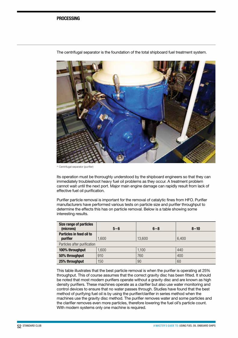
52 STANDARD CLUB A MASTER’S GUIDE TO: USING FUEL OIL ONBOARD SHIPS
PRocessInG
The centrifugal separator is the foundation of the total shipboard fuel treatment system.
^ Centrifugal separator (purifier)
Its operation must be thoroughly understood by the shipboard engineers so that they can immediately troubleshoot heavy fuel oil problems as they occur. A treatment problem cannot wait until the next port. Major main engine damage can rapidly result from lack of effective fuel oil purification.
Purifier particle removal is important for the removal of catalytic fines from HFO. Purifier manufacturers have performed various tests on particle size and purifier throughput to determine the effects this has on particle removal. Below is a table showing some interesting results.
size range of particles (microns) 5– 6 6 –8 8–10
Particles in feed oil to purifier 1,600 13,600 6,400
Particles after purification
100% throughput 1,600 1,100 440
50% throughput 910 760 400
25% throughput 150 90 60
This table illustrates that the best particle removal is when the purifier is operating at 25% throughput. This of course assumes that the correct gravity disc has been fitted. It should be noted that most modern purifiers operate without a gravity disc and are known as high density purifiers. These machines operate as a clarifier but also use water monitoring and control devices to ensure that no water passes through. Studies have found that the best method of purifying fuel oil is by using the purifier/clarifier in series method when the machines use the gravity disc method. The purifier removes water and some particles and the clarifier removes even more particles, therefore lowering the fuel oil’s particle count. With modern systems only one machine is required.
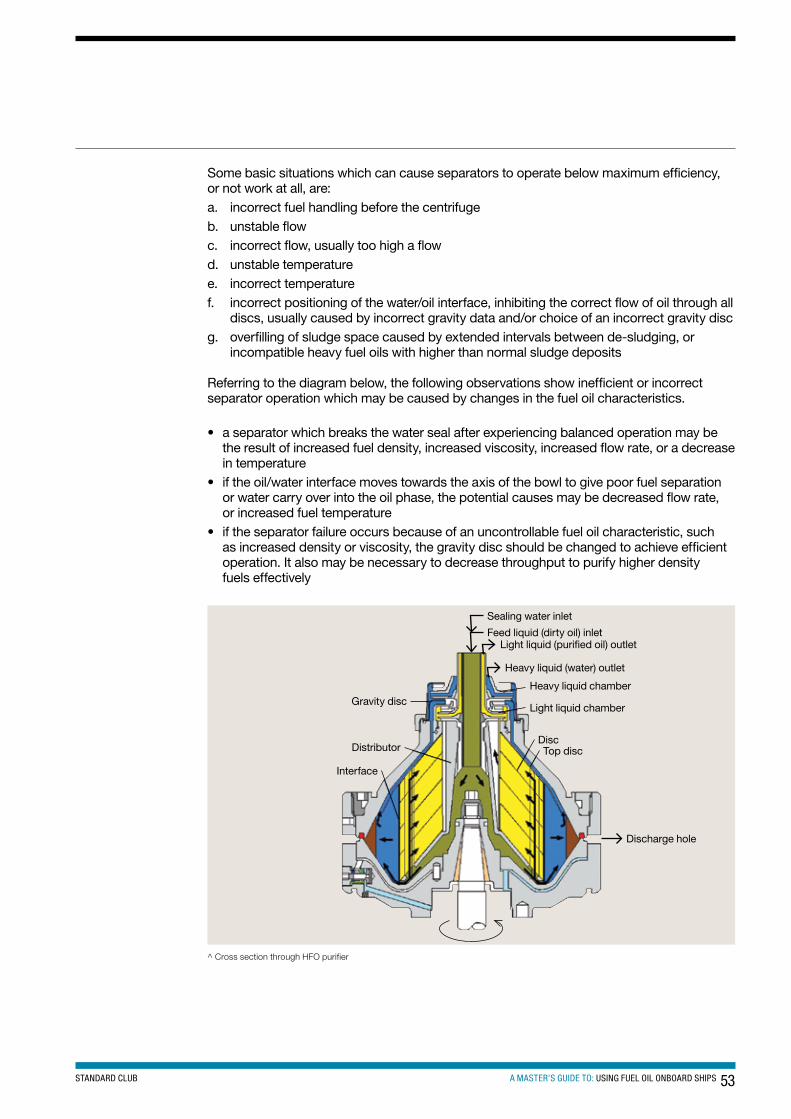
53A MASTER’S GUIDE TO: USING FUEL OIL ONBOARD SHIPSSTANDARD CLUB
Some basic situations which can cause separators to operate below maximum efficiency, or not work at all, are:a. incorrect fuel handling before the centrifuge b. unstable flow c. incorrect flow, usually too high a flow d. unstable temperature e. incorrect temperature f. incorrect positioning of the water/oil interface, inhibiting the correct flow of oil through all
discs, usually caused by incorrect gravity data and/or choice of an incorrect gravity disc g. overfilling of sludge space caused by extended intervals between de-sludging, or
incompatible heavy fuel oils with higher than normal sludge deposits
Referring to the diagram below, the following observations show inefficient or incorrect separator operation which may be caused by changes in the fuel oil characteristics.
• a separator which breaks the water seal after experiencing balanced operation may be the result of increased fuel density, increased viscosity, increased flow rate, or a decrease in temperature
• if the oil/water interface moves towards the axis of the bowl to give poor fuel separation or water carry over into the oil phase, the potential causes may be decreased flow rate, or increased fuel temperature
• if the separator failure occurs because of an uncontrollable fuel oil characteristic, such as increased density or viscosity, the gravity disc should be changed to achieve efficient operation. It also may be necessary to decrease throughput to purify higher density fuels effectively
Discharge hole
Top discDisc
Light liquid chamber
Heavy liquid chamber
Heavy liquid (water) outlet
Light liquid (purified oil) outletFeed liquid (dirty oil) inlet
Sealing water inlet
Interface
Distributor
Gravity disc
^ Cross section through HFO purifier
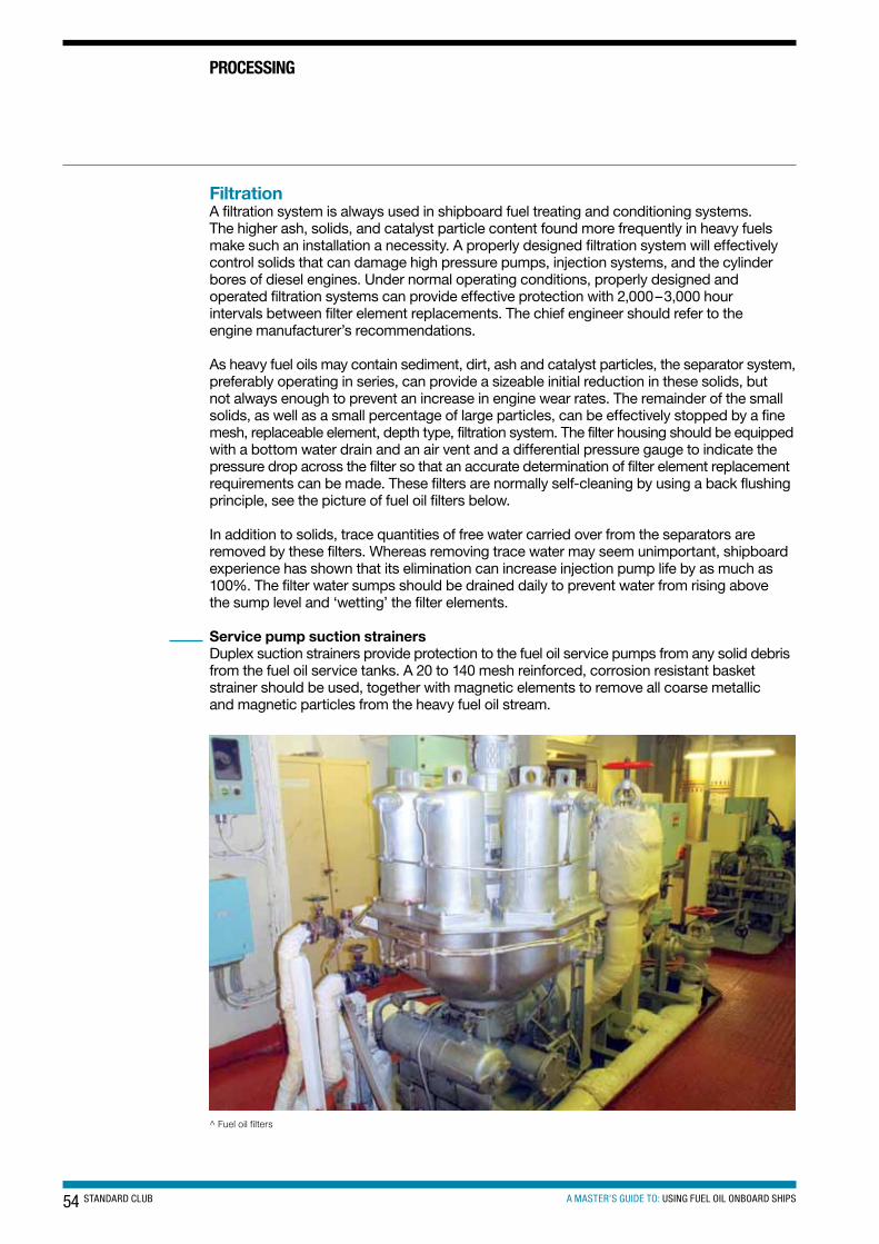
54 STANDARD CLUB A MASTER’S GUIDE TO: USING FUEL OIL ONBOARD SHIPS
PRocessInG
FiltrationA filtration system is always used in shipboard fuel treating and conditioning systems. The higher ash, solids, and catalyst particle content found more frequently in heavy fuels make such an installation a necessity. A properly designed filtration system will effectively control solids that can damage high pressure pumps, injection systems, and the cylinder bores of diesel engines. Under normal operating conditions, properly designed and operated filtration systems can provide effective protection with 2,000–3,000 hour intervals between filter element replacements. The chief engineer should refer to the engine manufacturer’s recommendations.
As heavy fuel oils may contain sediment, dirt, ash and catalyst particles, the separator system, preferably operating in series, can provide a sizeable initial reduction in these solids, but not always enough to prevent an increase in engine wear rates. The remainder of the small solids, as well as a small percentage of large particles, can be effectively stopped by a fine mesh, replaceable element, depth type, filtration system. The filter housing should be equipped with a bottom water drain and an air vent and a differential pressure gauge to indicate the pressure drop across the filter so that an accurate determination of filter element replacement requirements can be made. These filters are normally self-cleaning by using a back flushing principle, see the picture of fuel oil filters below.
In addition to solids, trace quantities of free water carried over from the separators are removed by these filters. Whereas removing trace water may seem unimportant, shipboard experience has shown that its elimination can increase injection pump life by as much as 100%. The filter water sumps should be drained daily to prevent water from rising above the sump level and ‘wetting’ the filter elements.
Service pump suction strainersDuplex suction strainers provide protection to the fuel oil service pumps from any solid debris from the fuel oil service tanks. A 20 to 140 mesh reinforced, corrosion resistant basket strainer should be used, together with magnetic elements to remove all coarse metallic and magnetic particles from the heavy fuel oil stream.
^ Fuel oil filters
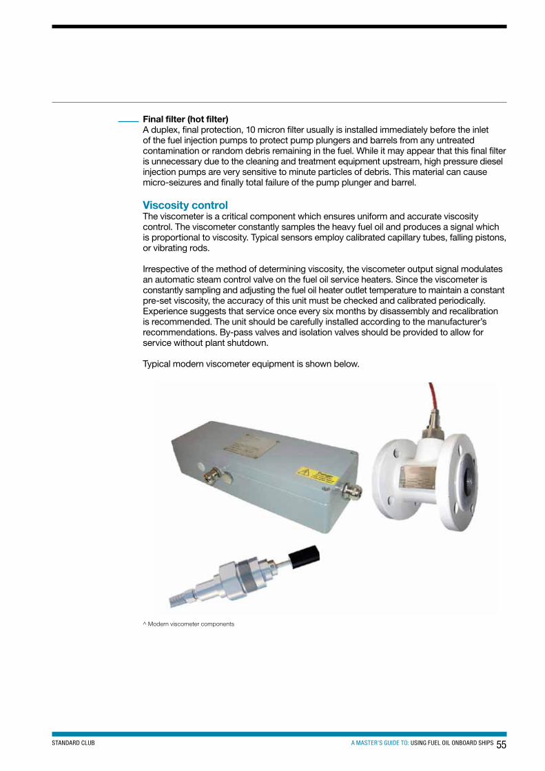
55A MASTER’S GUIDE TO: USING FUEL OIL ONBOARD SHIPSSTANDARD CLUB
Final filter (hot filter)A duplex, final protection, 10 micron filter usually is installed immediately before the inlet of the fuel injection pumps to protect pump plungers and barrels from any untreated contamination or random debris remaining in the fuel. While it may appear that this final filter is unnecessary due to the cleaning and treatment equipment upstream, high pressure diesel injection pumps are very sensitive to minute particles of debris. This material can cause micro-seizures and finally total failure of the pump plunger and barrel.
Viscosity controlThe viscometer is a critical component which ensures uniform and accurate viscosity control. The viscometer constantly samples the heavy fuel oil and produces a signal which is proportional to viscosity. Typical sensors employ calibrated capillary tubes, falling pistons, or vibrating rods.
Irrespective of the method of determining viscosity, the viscometer output signal modulates an automatic steam control valve on the fuel oil service heaters. Since the viscometer is constantly sampling and adjusting the fuel oil heater outlet temperature to maintain a constant pre-set viscosity, the accuracy of this unit must be checked and calibrated periodically. Experience suggests that service once every six months by disassembly and recalibration is recommended. The unit should be carefully installed according to the manufacturer’s recommendations. By-pass valves and isolation valves should be provided to allow for service without plant shutdown.
Typical modern viscometer equipment is shown below.
^ Modern viscometer components
56 STANDARD CLUB A MASTER’S GUIDE TO: USING FUEL OIL ONBOARD SHIPS
Main engines and boilersFuel oil that is used in engines or boilers must be heated in order to ensure correct atomisation upon injection. The necessary preheating temperature depends on the specific viscosity of the oil in question.
Inadequate preheating (that is, too high viscosity): • affects combustion • may cause increased cylinder wear of liners and rings• may be detrimental to exhaust valve seats • may result in too high fuel injection pressures, leading to excessive mechanical stresses
in the fuel oil system pumps and piping
In most installations, heating is carried out by means of steam coils, and the resulting viscosity is measured by a viscosity regulator (viscometer), which also controls the steam supply. Depending on the viscosity/temperature relationship and the viscosity of the fuel oil, an outlet temperature of up to 150°C may be necessary. (Refer to the above section on viscosity control.) However, in order to avoid too rapid fouling of the heater, a temperature of 150°C should not be exceeded.
Recommended viscosity meter setting is 10–15 cSt. However the engine manufacturer’s recommended setting for the fuel being used should always be followed.
Fuel oil injection temperature is determined by the fuel oil’s viscosity and is normally in the range of 105–150°C.
Boilers tend to be much more tolerant when it comes to burning heavy fuel oil. The fuel oil does not have to pass though high pressure fuel oil pumps with very small clearances and small pin holes in fuel injector nozzles. The boiler’s fuel oil injection system is normally at a much lower pressure than a diesel engine: typically 250–300 bar for a diesel engine and 1.5–3.5 bar for a boiler burner. Also the boiler is more tolerant with fuel oil temperature and normally does not require a viscometer before being fired in to the furnace and burnt.
Technical issues of operating on low sulphur diesel fuel oil when following the EU Sulphur Directive 2005/33/EC.
All owners are familiar with the current MARPOL Annex VI regulations with respect to SOx emission controlled areas (ECAs). Owners may already have low sulphur fuel for the use in main and auxiliary engines, but the continuous use of gas oil in diesel generators, boilers and incinerators designed for running on HFO, may pose some operational problems.
There are a number of technical issues of which owners should be aware with respect to the use of low sulphur fuel:• Low viscosity: It is necessary to determine what the viscosity limitations are for the
machinery in which the fuel is to be used. If a machine is designed to run on HFO, then the fuel system components will have been designed to run at HFO temperatures (approximately 110–120°C). Depending on the fuel system configuration it may be necessary to fit some or all of the following:
a. new fuel pumpsb. fuel injector nozzlesc. fuel line coolers to control the temperature of the gas oil in the fuel supply system
to ensure correct atomisation. d. new return lines may have to be installed if contamination by HFO is to be avoided. e. the replacement or the addition of gear type supply pumps may also have to
be considered.The above list is not complete and may be expanded.
MAcHIneRY UsInG FUeL oIL07
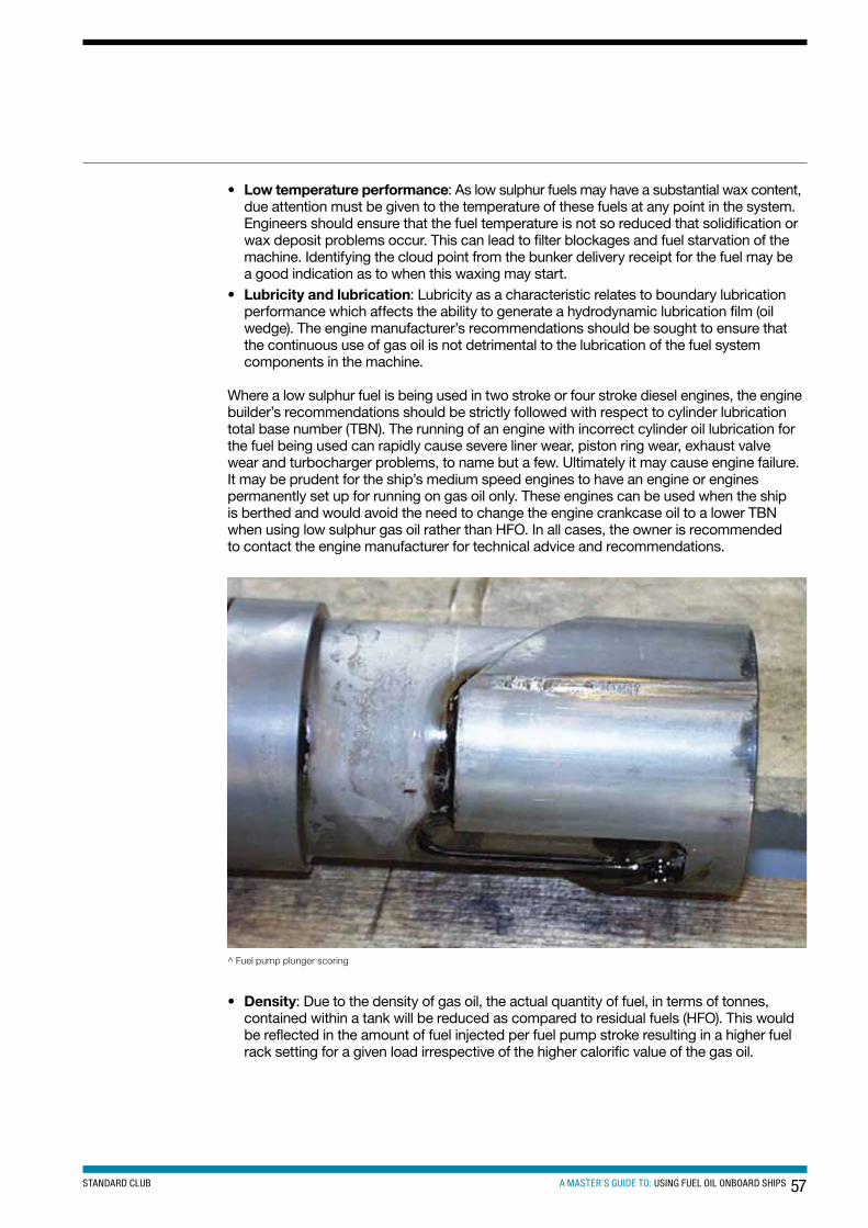
57A MASTER’S GUIDE TO: USING FUEL OIL ONBOARD SHIPSSTANDARD CLUB
• Low temperature performance: As low sulphur fuels may have a substantial wax content, due attention must be given to the temperature of these fuels at any point in the system. Engineers should ensure that the fuel temperature is not so reduced that solidification or wax deposit problems occur. This can lead to filter blockages and fuel starvation of the machine. Identifying the cloud point from the bunker delivery receipt for the fuel may be a good indication as to when this waxing may start.
• Lubricity and lubrication: Lubricity as a characteristic relates to boundary lubrication performance which affects the ability to generate a hydrodynamic lubrication film (oil wedge). The engine manufacturer’s recommendations should be sought to ensure that the continuous use of gas oil is not detrimental to the lubrication of the fuel system components in the machine.
Where a low sulphur fuel is being used in two stroke or four stroke diesel engines, the engine builder’s recommendations should be strictly followed with respect to cylinder lubrication total base number (TBN). The running of an engine with incorrect cylinder oil lubrication for the fuel being used can rapidly cause severe liner wear, piston ring wear, exhaust valve wear and turbocharger problems, to name but a few. Ultimately it may cause engine failure. It may be prudent for the ship’s medium speed engines to have an engine or engines permanently set up for running on gas oil only. These engines can be used when the ship is berthed and would avoid the need to change the engine crankcase oil to a lower TBN when using low sulphur gas oil rather than HFO. In all cases, the owner is recommended to contact the engine manufacturer for technical advice and recommendations.
^ Fuel pump plunger scoring
• Density: Due to the density of gas oil, the actual quantity of fuel, in terms of tonnes, contained within a tank will be reduced as compared to residual fuels (HFO). This would be reflected in the amount of fuel injected per fuel pump stroke resulting in a higher fuel rack setting for a given load irrespective of the higher calorific value of the gas oil.
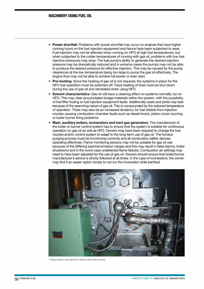
58 STANDARD CLUB A MASTER’S GUIDE TO: USING FUEL OIL ONBOARD SHIPS
MAcHIneRY UsInG FUeL oIL
• Power shortfall: Problems with power shortfall may occur on engines that have higher running hours on the fuel injection equipment and hence have been subjected to wear. Fuel injection may not be affected when running on HFO at high fuel temperatures, but when subjected to the colder temperatures of running with gas oil, problems with low fuel injection pressures may arise. The fuel pump’s ability to generate the desired injection pressure may be dramatically reduced and in extreme cases the pumps may not be able to produce the desired pressure for effective injection. This may be caused by the pump clearances at the low temperature being too large to pump the gas oil effectively. The engine thus may not be able to achieve full power or even start.
• Pre-heating: Since the heating of gas oil is not required, the systems in place for the HFO fuel operation must be switched off. Trace heating of lines must be shut down during the use of gas oil and reinstated when using HFO.
• Solvent characteristics: Gas oil will have a cleaning effect on systems normally run on HFO. This may clear accumulated sludge materials within the system, with the possibility of fuel filter fouling or fuel injection equipment faults. Additionally seals and joints may leak because of the searching nature of gas oil. This is compounded by the reduced temperature of operation. There may also be an increased tendency for fuel dribble from injection nozzles causing combustion chamber faults such as diesel knock, piston crown burning or boiler burner firing problems.
• Main, auxiliary boilers, incinerators and inert gas generators: The manufacturer of the boiler or burner control system has to ensure that the system is suitable for continuous operation on gas oil as well as HFO. Owners may have been required to change the fuel nozzles and/or control system to adapt to the long-term use of gas oil. The furnace purging process must be functioning correctly and all combustion safety devices operating effectively. Flame monitoring sensors may not be suitable for gas oil use because of the differing spectral emission ranges and this may result in false alarms, boiler shutdowns and in the worst case undetected flame failures. Combustion air settings may need to have been adjusted for the use of gas oil. Owners should ensure that boiler/burner manufacturer’s advice is strictly followed at all times. In the case of incinerators, the owner may find it an easier option simply to not run the incinerator while berthed.
^ Always follow manufacturer’s advice with boiler burners
59A MASTER’S GUIDE TO: USING FUEL OIL ONBOARD SHIPSSTANDARD CLUB
• Approval of modifications: All the proposed modifications to combustion equipment should have been assessed by a hazardous operations (HAZOP) workshop or other suitable risk assessment. Where any modifications have been made, these must have been approved by the ship’s classification society.
• Changeover procedures: As previously discussed in chapter 5.
Use of the incineratorMost shipboard incinerators use diesel oil as their primary fuel and have the capability to burn ship’s waste oil using a separate burner.
Shipboard incineration is allowed only in purpose-built approved marine incinerators, but incineration of sewage sludge and sludge oil generated during the normal operation of a ship may also take place in the main or auxiliary power plant or boilers, but in those cases, shall not take place inside ports, harbours and estuaries.
Check that for incinerators up to 1500 kW installed on or after 1 January 2000, a type approval certificate, according to MEPC76(40) or MED certification, is available.
For incinerators installed on or after 1 January 2000 but before 19 May 2005, not type approved according to Resolution MEPC.76(40), exemption may be requested from the relevant maritime administration, if the ship trades only in national waters.
Shipboard incineration of the following substances is prohibited: a. residues of cargo subject to Annex I, II and III of the Convention and related
contaminated packing materials b. polychlorinated biphenyls (pcbs)c. garbage, as defined in Annex V of the Convention, containing more than traces
of heavy metalsd. refined petroleum products containing halogen compoundse. polyvinyl chlorides (pvcs), except in incinerators approved according to MEPC76(40)
or MEPC59(33)
Modification of operational instructions must be made to comply with the above. Check that complete instructions and incinerator maintenance manuals are available onboard and give instructions concerning operation of the incinerator to achieve the limits specified in MEPC 76(40). Check that a system for the continuous monitoring of the temperature of combustion gases is available. For the management of solid waste derived from incineration, reference is to be made to Annex V of MARPOL 73/78. Continuous feeding systems are to be arranged so that the supply of waste is stopped if the flue gas outlet temperature decreases below 850°C.
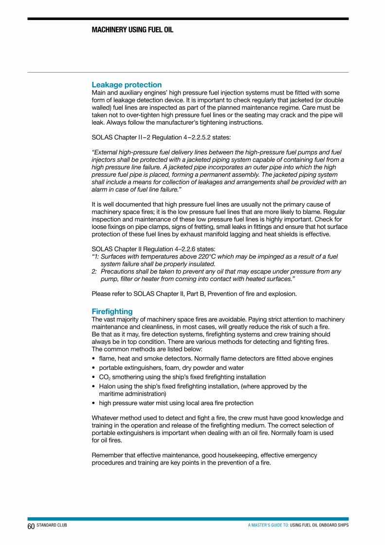
60 STANDARD CLUB A MASTER’S GUIDE TO: USING FUEL OIL ONBOARD SHIPS
Leakage protectionMain and auxiliary engines’ high pressure fuel injection systems must be fitted with some form of leakage detection device. It is important to check regularly that jacketed (or double walled) fuel lines are inspected as part of the planned maintenance regime. Care must be taken not to over-tighten high pressure fuel lines or the seating may crack and the pipe will leak. Always follow the manufacturer’s tightening instructions.
SOLAS Chapter II–2 Regulation 4–2.2.5.2 states:
“External high-pressure fuel delivery lines between the high-pressure fuel pumps and fuel injectors shall be protected with a jacketed piping system capable of containing fuel from a high pressure line failure. A jacketed pipe incorporates an outer pipe into which the high pressure fuel pipe is placed, forming a permanent assembly. The jacketed piping system shall include a means for collection of leakages and arrangements shall be provided with an alarm in case of fuel line failure.”
It is well documented that high pressure fuel lines are usually not the primary cause of machinery space fires; it is the low pressure fuel lines that are more likely to blame. Regular inspection and maintenance of these low pressure fuel lines is highly important. Check for loose fixings on pipe clamps, signs of fretting, small leaks in fittings and ensure that hot surface protection of these fuel lines by exhaust manifold lagging and heat shields is effective.
SOLAS Chapter II Regulation 4–2.2.6 states:“1: Surfaces with temperatures above 220°C which may be impinged as a result of a fuel
system failure shall be properly insulated.2: Precautions shall be taken to prevent any oil that may escape under pressure from any
pump, filter or heater from coming into contact with heated surfaces.”
Please refer to SOLAS Chapter II, Part B, Prevention of fire and explosion.
FirefightingThe vast majority of machinery space fires are avoidable. Paying strict attention to machinery maintenance and cleanliness, in most cases, will greatly reduce the risk of such a fire. Be that as it may, fire detection systems, firefighting systems and crew training should always be in top condition. There are various methods for detecting and fighting fires. The common methods are listed below:• flame, heat and smoke detectors. Normally flame detectors are fitted above engines• portable extinguishers, foam, dry powder and water• CO2 smothering using the ship’s fixed firefighting installation• Halon using the ship’s fixed firefighting installation, (where approved by the
maritime administration)• high pressure water mist using local area fire protection
Whatever method used to detect and fight a fire, the crew must have good knowledge and training in the operation and release of the firefighting medium. The correct selection of portable extinguishers is important when dealing with an oil fire. Normally foam is used for oil fires.
Remember that effective maintenance, good housekeeping, effective emergency procedures and training are key points in the prevention of a fire.
MAcHIneRY UsInG FUeL oIL
61A MASTER’S GUIDE TO: USING FUEL OIL ONBOARD SHIPSSTANDARD CLUB
Cleanliness• keep a clean engine room. This helps reduce waste oil/water and reduces need for
disposal and use of the OWS• always ensure that save-alls are drained of water before bunkering, taking care to ensure
any residual oil in the save-all is not allowed into the sea. Use a portable hand pump if required
• clean and maintain bunkering valves and in-line filters if fitted, by following the ship’s planned maintenance schedules. Failure to maintain bunkering valves may allow them to leak
• always leave the bunkering area clean when bunkers have been completed. Accidental small spillages will present a slip hazard
• do not forget to fit securely bunkering manifold blank flanges, ensuring that the gasket is in a satisfactory condition
• remember that oil is carcinogenic (cancer causing). Ensure suitable personal protective equipment is used at all times when handling fuel oil. Refer to material safety data sheets for HFO for precautions and information
Management of change• whenever taking over a ship from previous ownership, check the fuel waste oil systems
particularly for ‘magic pipes’, the term for retro-fitted pipes that circumvent the original piping system and could well lead to MARPOL infringements. The club recommends that the chief engineer and superintendent trace the waste oil and bilge lines when taking over a previously owned ship
• refer to the ship’s drawings and inspect any pump that can take suction from the bilges directly and discharge overboard. Ensure that these pumps are well marked and that suitable pollution prevention procedures are followed
• carry out oily water separator (OWS) training for ship staff who may not be familiar with the operation of the OWS. Ensure that the training details are recorded
• always ensure that ship staff engaged in bunkering are fully familiar with the procedures and are supervised by experienced personnel before being left in charge of the system valve set-up
FamiliarisationFamiliarisation of ships systems and equipment is important before they are used or operated. Many bunker spills occur as a result of the engineers in charge of the bunkering operation not being familiar with:• bunker piping arrangement and isolation valves• tank capacities and sounding tables• pumping anomalies• overflow alarms• reliability of tank gauges/soundings• tank configuration• safe maximum filling limits• emergency shutdowns
ADDItIonAL PRecAUtIons08
62 STANDARD CLUB A MASTER’S GUIDE TO: USING FUEL OIL ONBOARD SHIPS
ADDItIonAL PRecAUtIons
It is important that engineers should receive good handovers and handover information before bunkering a ship for the first time. Bunkering a ship or a tank for the first time should be considered as a ‘high risk’ activity and additional precautions may need to be considered, such as:• reduced pumping rates• additional personnel involved• experienced engineer overseeing operation
Bunker fuel taggingThere are on the market various forms of bunker tags. These are unique organic molecular markers that have been developed specifically for ‘fingerprinting’ heavy fuel oil. These molecular markers, also known as taggants, have been designed and engineered to be detected very accurately, at extremely low levels within residual fuel oil. Molecular markers have virtually the same physical and chemical properties as heavy fuel oil and therefore cannot be removed without destroying the oil itself.
Molecular markers are organic compounds that are highly secure and stable within heavy fuel oil such that they resist removal by any chemical, thermal or physical treatment.
Treatment by the markers works out to approximately half a teaspoon to every 30 tonnes of bunkers (approximately 100 parts per billion (ppb)). This small amount of tracer must be administered by dilution. Usually a 1 litre container is administered to the HFO during bunkering. Treatment gives a ratio of about 100–200 ppb. Detection in the fuel has been quoted as low as in terms of parts per trillion (ppt).
The technology is part of anti-theft, bunkering control operations by crude oil producers and transportation companies, and by national governments trying to eliminate crude oil theft. It may also be used by companies in arbitration proceedings with respect to pollution incidents.
Tagging products can be applied to all aspects of marine operations relating to potential pollution incidents: bunkers, cargo, bilges, and tank washings. The use of this technology can be used as proof of innocence as well as proof of guilt.
The tagging product can be manufactured to allow shipping companies to have a unique molecular marking product for every ship in their fleet. Bottles can be supplied to the ship with a unique product name and a unique bar code for identification. The costs involved have been quoted as around $2 to $4 per tonne of marked fuel for the manufacture and supply of a ship specific fuel molecular marker. The cost will depend on the quantity ordered.
The molecular marker for HFO is already used by some companies and has provided them with peace of mind over any allegations of fuel oil pollution they might unjustly face.
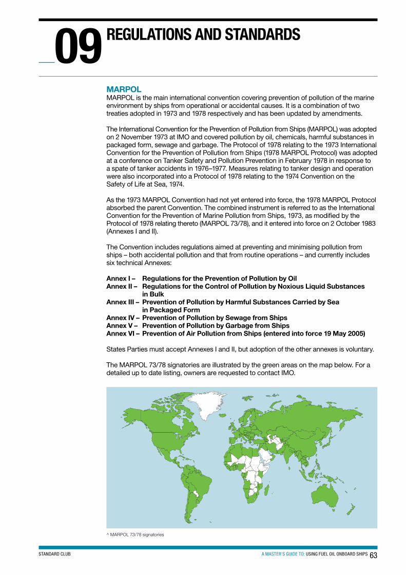
63A MASTER’S GUIDE TO: USING FUEL OIL ONBOARD SHIPSSTANDARD CLUB
MARPOLMARPOL is the main international convention covering prevention of pollution of the marine environment by ships from operational or accidental causes. It is a combination of two treaties adopted in 1973 and 1978 respectively and has been updated by amendments.
The International Convention for the Prevention of Pollution from Ships (MARPOL) was adopted on 2 November 1973 at IMO and covered pollution by oil, chemicals, harmful substances in packaged form, sewage and garbage. The Protocol of 1978 relating to the 1973 International Convention for the Prevention of Pollution from Ships (1978 MARPOL Protocol) was adopted at a conference on Tanker Safety and Pollution Prevention in February 1978 in response to a spate of tanker accidents in 1976–1977. Measures relating to tanker design and operation were also incorporated into a Protocol of 1978 relating to the 1974 Convention on the Safety of Life at Sea, 1974.
As the 1973 MARPOL Convention had not yet entered into force, the 1978 MARPOL Protocol absorbed the parent Convention. The combined instrument is referred to as the International Convention for the Prevention of Marine Pollution from Ships, 1973, as modified by the Protocol of 1978 relating thereto (MARPOL 73/78), and it entered into force on 2 October 1983 (Annexes I and II).
The Convention includes regulations aimed at preventing and minimising pollution from ships – both accidental pollution and that from routine operations – and currently includes six technical Annexes:
Annex I – Regulations for the Prevention of Pollution by OilAnnex II – Regulations for the Control of Pollution by Noxious Liquid Substances
in Bulk Annex III – Prevention of Pollution by Harmful Substances Carried by Sea
in Packaged FormAnnex IV – Prevention of Pollution by Sewage from Ships Annex V – Prevention of Pollution by Garbage from ShipsAnnex VI – Prevention of Air Pollution from Ships (entered into force 19 May 2005)
States Parties must accept Annexes I and II, but adoption of the other annexes is voluntary.
The MARPOL 73/78 signatories are illustrated by the green areas on the map below. For a detailed up to date listing, owners are requested to contact IMO.
^ MARPOL 73/78 signatories
ReGULAtIons AnD stAnDARDs09
64 STANDARD CLUB A MASTER’S GUIDE TO: USING FUEL OIL ONBOARD SHIPS
Detentions frequently occur on ships for MARPOL Annex VI deficiencies, and owners should ensure that their ships comply at all times.
The following is list of MARPOL Annex VI detainable deficiencies. It is by no means exhaustive, but it provides a good indication of the purposes of Annex VI:• the absence of a valid International Air Pollution Prevention (IAPP) Certificate, Engine
International Air Pollution Prevention (EIAPP) certificate, or Technical Files (ships built in 2000 and onward)
• a diesel engine for which an EIAPP Certificate is required, which does not meet the NOx Technical Code
• the sulphur content of the onboard bunkers exceeds 4.5%• non-compliance with SECA requirements in European/USA waters• an incinerator or required emission scrubbers not meeting approval requirements,
or meeting such requirements, but not functioning properly• ozone-depleting substances are being emitted• the ship has an incomplete file of bunker delivery receipts and associated fuel samples• master or crew unfamiliar with operational procedures regarding air pollution
prevention equipment
The current and future regulations for MARPOL Annex VIThe Marine Environment Protection Committee (MEPC) of the International Maritime Organization (IMO) unanimously adopted amendments to the MARPOL Annex VI regulations to reduce harmful emissions from ships even further, when it met for its 58th session at IMO’s London headquarters on 6–10 October 2008.
The main changes to MARPOL Annex VI will see a progressive reduction in sulphur oxide (SOx) emissions from ships, with the global sulphur cap reduced initially to 3.5% (from the current 4.5%), from 1 January 2012; then progressively to 0.5 %, from 1 January 2020, subject to a feasibility review to be completed no later than 2018.
The limits applicable in SOx Emission Control Areas (ECAs) have been reduced to 1%, on 1 July 2010 (from the previous 1.5 %); being further reduced to 0.1 %, effective from 1 January 2015.
Progressive reductions in nitrogen oxide (NOx) emissions from marine engines were also agreed, with the most stringent controls on so-called ‘Tier III’ engines, that is those installed on ships constructed on or after 1 January 2016, operating in Emission Control Areas.
The revised Annex VI will allow for an Emission Control Area to be designated for SOx, particulate matter, or NOx, or all three types of emissions from ships, subject to a proposal from a party or parties to the Annex, which would be considered for adoption by IMO, if supported by a demonstrated need to prevent, reduce and control one or more of those emissions from ships.
All ships constructed on or after 1 January 2000 must have a Technical File which identifies the engine’s components, settings or operating values which influence exhaust emissions. The Technical File must be prepared by the engine manufacturer and approved by the relevant certifying authority, and is required to accompany an engine throughout its life on board the ship. It must be maintained in good order and not be subjected to any unauthorised alteration, amendments, omission or deletions. The engine to which the Technical File refers is to be installed in accordance with the rating (kW and speed) and duty cycle as approved together with any limitation imposed by the Technical File.
ReGULAtIons AnD stAnDARDs
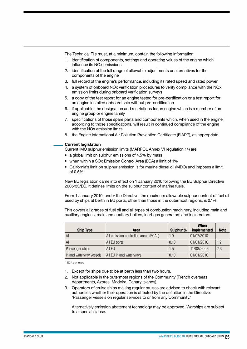
65A MASTER’S GUIDE TO: USING FUEL OIL ONBOARD SHIPSSTANDARD CLUB
The Technical File must, at a minimum, contain the following information:1. identification of components, settings and operating values of the engine which
influence its NOx emissions2. identification of the full range of allowable adjustments or alternatives for the
components of the engine3. full record of the engine’s performance, including its rated speed and rated power4. a system of onboard NOx verification procedures to verify compliance with the NOx
emission limits during onboard verification surveys5. a copy of the test report for an engine tested for pre-certification or a test report for
an engine installed onboard ship without pre-certification6. if applicable, the designation and restrictions for an engine which is a member of an
engine group or engine family7. specifications of those spare parts and components which, when used in the engine,
according to those specifications, will result in continued compliance of the engine with the NOx emission limits
8. the Engine International Air Pollution Prevention Certificate (EIAPP), as appropriate
Current legislationCurrent IMO sulphur emission limits (MARPOL Annex VI regulation 14) are:• a global limit on sulphur emissions of 4.5% by mass• when within a SOx Emission Control Area (ECA) a limit of 1%• California’s limit on sulphur emission is for marine diesel oil (MDO) and imposes a limit
of 0.5% New EU legislation came into effect on 1 January 2010 following the EU Sulphur Directive 2005/33/EC. It defines limits on the sulphur content of marine fuels.
From 1 January 2010, under the Directive, the maximum allowable sulphur content of fuel oil used by ships at berth in EU ports, other than those in the outermost regions, is 0.1%.
This covers all grades of fuel oil and all types of combustion machinery, including main and auxiliary engines, main and auxiliary boilers, inert gas generators and incinerators.
ship type Area sulphur %When
implemented noteAll All emission controlled areas (ECAs) 1.0 01/07/2010
All All EU ports 0.10 01/01/2010 1,2
Passenger ships All EU 1.5 11/08/2006 2,3
Inland waterway vessels All EU inland waterways 0.10 01/01/2010
^ ECA summary
1. Except for ships due to be at berth less than two hours.2. Not applicable in the outermost regions of the Community (French overseas
departments, Azores, Madeira, Canary Islands).3. Operators of cruise ships making regular cruises are advised to check with relevant
authorities whether their operation is affected by the definition in the Directive: ‘Passenger vessels on regular services to or from any Community.’
Alternatively emission abatement technology may be approved. Warships are subject to a special clause.
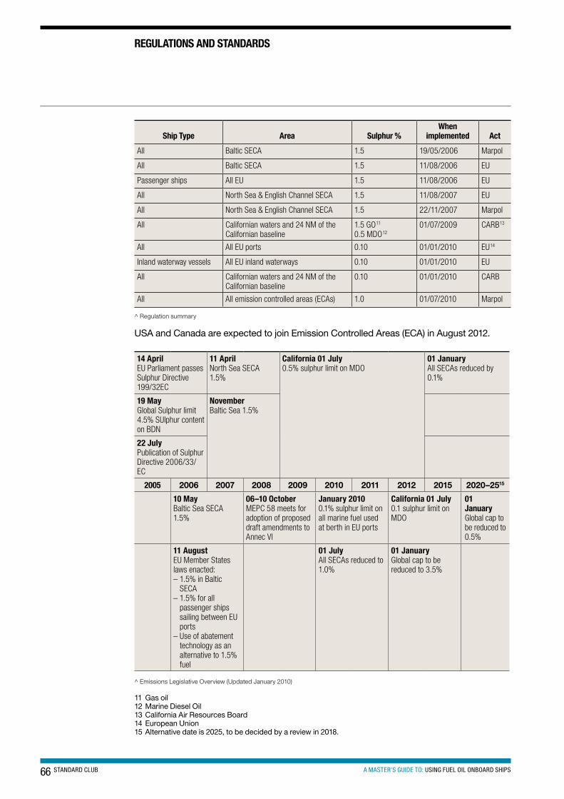
66 STANDARD CLUB A MASTER’S GUIDE TO: USING FUEL OIL ONBOARD SHIPS
ReGULAtIons AnD stAnDARDs
ship type Area sulphur %When
implemented Act
All Baltic SECA 1.5 19/05/2006 Marpol
All Baltic SECA 1.5 11/08/2006 EU
Passenger ships All EU 1.5 11/08/2006 EU
All North Sea & English Channel SECA 1.5 11/08/2007 EU
All North Sea & English Channel SECA 1.5 22/11/2007 Marpol
All Californian waters and 24 NM of the Californian baseline
1.5 GO11
0.5 MDO1201/07/2009 CARB13
All All EU ports 0.10 01/01/2010 EU14
Inland waterway vessels All EU inland waterways 0.10 01/01/2010 EU
All Californian waters and 24 NM of the Californian baseline
0.10 01/01/2010 CARB
All All emission controlled areas (ECAs) 1.0 01/07/2010 Marpol
^ Regulation summary
USA and Canada are expected to join Emission Controlled Areas (ECA) in August 2012.
14 AprilEU Parliament passes Sulphur Directive 199/32EC
11 AprilNorth Sea SECA 1.5%
california 01 July0.5% sulphur limit on MDO
01 JanuaryAll SECAs reduced by 0.1%
19 MayGlobal Sulphur limit 4.5% SUlphur content on BDN
novemberBaltic Sea 1.5%
22 JulyPublication of Sulphur Directive 2006/33/EC
2005 2006 2007 2008 2009 2010 2011 2012 2015 2020–2515
10 MayBaltic Sea SECA 1.5%
06–10 octoberMEPC 58 meets for adoption of proposed draft amendments to Annec Vl
January 20100.1% sulphur limit on all marine fuel used at berth in EU ports
california 01 July0.1 sulphur limit on MDO
01 JanuaryGlobal cap to be reduced to 0.5%
11 AugustEU Member States laws enacted:– 1.5% in Baltic
SECA– 1.5% for all
passenger ships sailing between EU ports
– Use of abatement technology as an alternative to 1.5% fuel
01 JulyAll SECAs reduced to 1.0%
01 JanuaryGlobal cap to be reduced to 3.5%
^ Emissions Legislative Overview (Updated January 2010)
11 Gas oil12 Marine Diesel Oil13 California Air Resources Board14 European Union15 Alternative date is 2025, to be decided by a review in 2018.
67A MASTER’S GUIDE TO: USING FUEL OIL ONBOARD SHIPSSTANDARD CLUB
How does this affect ships?These low sulphur fuel oil requirements apply to all ships irrespective of flag (EU or non-EU), ship type, and date of construction or tonnage.
At present, it has been stated that there will be no dispensations granted to ships other than those visiting the outermost EU regions. The outermost regions are the French overseas departments, the Azores, Madeira and the Canary Islands. In each of these cases the local air quality standards must be maintained.
The use of residual fuel in slow speed main engines will still be allowed as these are not run continuously in port and the regulations do allow for the ship to enter and leave the berth using low sulphur residual fuel. Time is allowed for manoeuvring alongside and start-up before leaving the berth. The legislation is applicable to machinery using fuel oil that will only be running when the ship is berthed.
A limit of 0.1% sulphur content means that the use of residual fuel oil during time at the berth is not permitted unless the use of exhaust gas scrubbers or selective catalytic reduction is employed and monitored by the use of emissions monitoring equipment. This is commonly referred to as the use of abatement technology. Owners are therefore faced with the use of gas oil only when at EU berths unless they have abatement technology fitted to the equipment in use at that time.
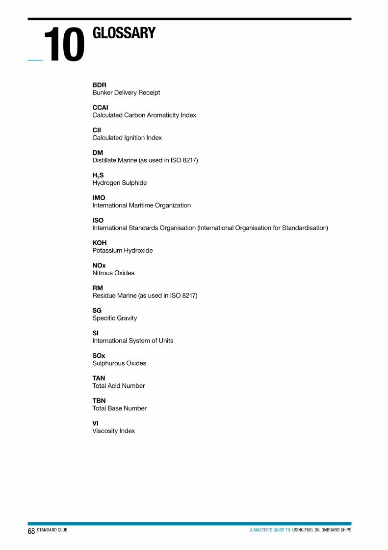
68 STANDARD CLUB A MASTER’S GUIDE TO: USING FUEL OIL ONBOARD SHIPS
BDR Bunker Delivery Receipt
CCAI Calculated Carbon Aromaticity Index
CII Calculated Ignition Index
DM Distillate Marine (as used in ISO 8217)
H2S Hydrogen Sulphide
IMO International Maritime Organization
ISO International Standards Organisation (International Organisation for Standardisation)
KOH Potassium Hydroxide
NOx Nitrous Oxides
RM Residue Marine (as used in ISO 8217)
SG Specific Gravity
SI International System of Units
SOx Sulphurous Oxides
TAN Total Acid Number
TBN Total Base Number
VI Viscosity Index
GLossARY10
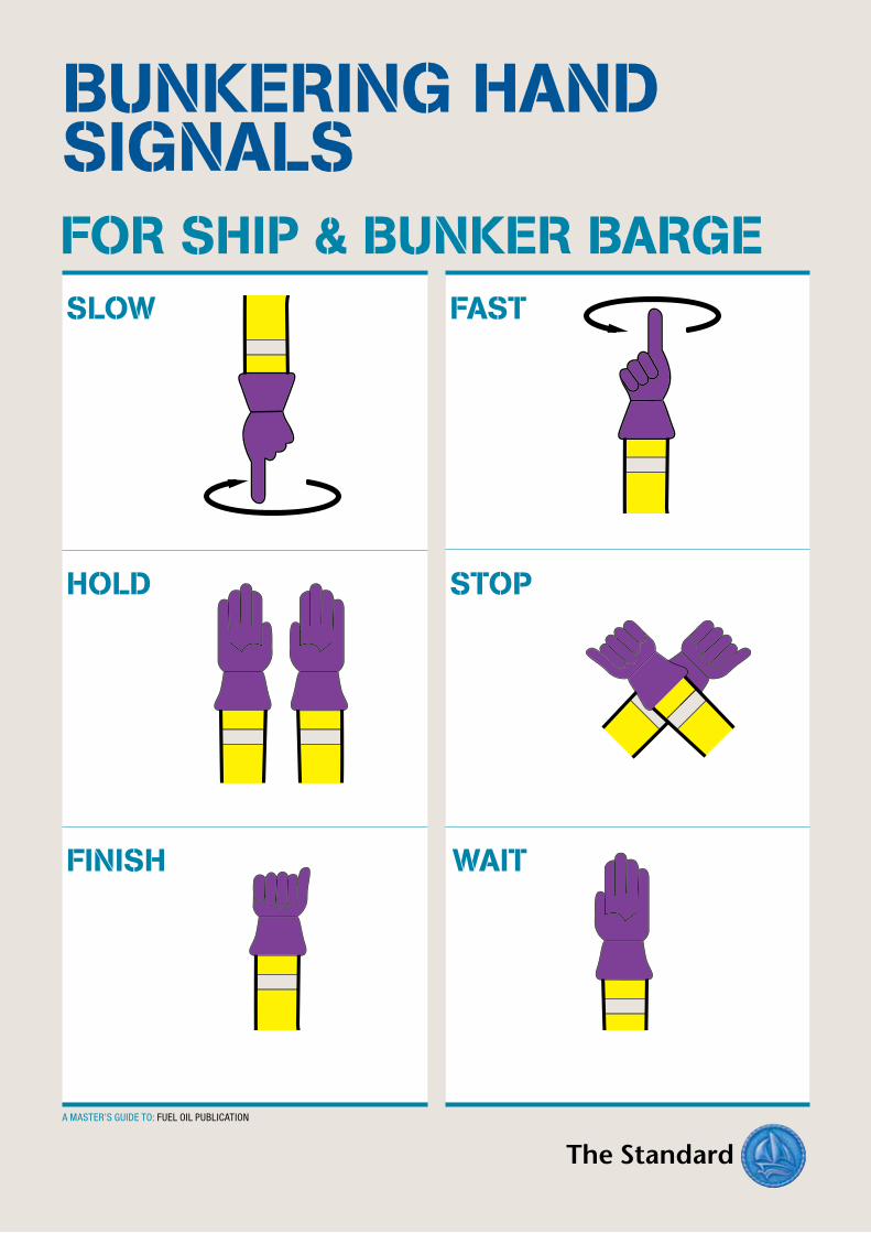
SLOW FAST
HOLD
FINISH WAIT
STOP
FOR SHIP & BUNKER BARGE
BUNKERING HAND SIGNALS
A MASTER’S GUIDE TO: FUEL OIL PUBLICATION
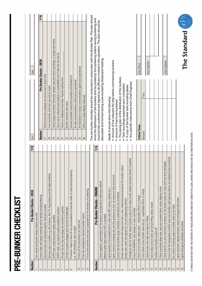
PRe-
BUnK
eR c
HecK
LIst
num
ber
Pre-
Bunk
er c
heck
s –
DecK
Y/n
1O
wn
vess
el a
nd b
unke
r bar
ge p
rope
rly s
ecur
ed
2En
sure
shi
ps a
nd b
arge
moo
rings
will
be te
nded
dur
ing
bunk
erin
g
3Se
a/w
ind
stat
e an
d ex
pect
ed w
eath
er fo
reca
st c
heck
ed
4W
arni
ng s
igns
in p
ositi
on e
.g. N
o Sm
okin
g, R
ed ‘B
’ Fla
g ho
iste
d an
d Re
d lig
ht e
xhib
ited
5SO
PEP
plan
und
erst
ood
and
read
ily a
vaila
ble
6SO
PEP
clea
n-up
mat
eria
l rea
dily
avai
labl
e/in
pos
ition
7Al
l sav
e-al
l and
drip
tray
plu
gs a
re s
crew
ed in
pos
ition
8Al
l dec
k sc
uppe
rs p
lugg
ed a
nd e
nsur
ed o
il/w
ater
tight
9Pr
ovis
ions
mad
e to
dra
in o
ff an
y ac
cum
ulat
ions
of s
ea/r
ain
wat
er o
n de
ck d
urin
g bu
nker
ing
e.
g. A
B st
andi
ng b
y op
en s
cupp
er
10En
sure
all
fire
prec
autio
ns a
re o
bser
ved
11Fo
am fi
re e
xtin
guis
her p
lace
d at
bun
ker s
tatio
n
12Al
l hot
wor
k pe
rmits
hav
e be
en s
uspe
nded
for t
he d
urat
ion
of b
unke
ring
num
ber
Pre-
Bunk
er c
heck
s –
enGI
neY/
n1
Chec
k su
pplie
rs’ s
peci
ficat
ion
for t
he p
rodu
ct c
orre
spon
ds to
wha
t was
ord
ered
2M
ater
ial s
afet
y da
ta s
heet
for H
FO is
ava
ilabl
e
3Ag
ree
quan
tity
to b
e su
pplie
d an
d in
wha
t uni
ts (M
³, to
nnes
, bar
rels
etc
.)
4Ag
ree
max
imum
pum
ping
rate
and
line
pre
ssur
e at
sta
rt, a
t max
imum
flow
and
at e
nd
5En
sure
that
the
bunk
er b
arge
che
cklis
t is
unde
rsto
od a
nd c
ompl
eted
6Bu
nker
pla
n di
scus
sed
with
bar
ge a
nd s
hip’
s cr
ew; u
nder
stoo
d an
d po
sted
at t
he b
unke
r sta
tion
Bu
nker
pla
n m
ade
and
sign
ed b
y C/
E an
d en
gine
erin
g of
ficer
s
7Em
erge
ncy
stop
for b
unke
r bar
ge tr
ansf
er p
ump
at th
e sh
ips
bunk
er s
tatio
n ha
s be
en te
sted
if s
uppl
ied
8En
sure
the
MAR
POL
drip
sam
pler
is c
lean
and
fitte
d
9Ch
eck
corr
ect b
unke
r val
ves
open
– re
spon
sibl
e of
ficer
in c
harg
e
10Cr
oss
chec
k co
rrec
t bun
ker v
alve
set
-up
– re
spon
sibl
e of
ficer
in c
harg
e
11Ch
eck
bunk
er ta
nk h
igh
leve
l ala
rms
if fit
ted
12Fu
el o
il da
ily s
ervi
ce ta
nks
are
full
and
fillin
g va
lves
clo
sed
13Pu
rifie
rs a
nd tr
ansf
er p
umps
off
14Ch
eck
soun
ding
/ulla
ge p
ipe
caps
are
scr
ewed
dow
n un
less
dip
ping
a ta
nk
15Ch
eck
that
the
air v
ents
and
flam
e ar
rest
ors
for t
he b
unke
r tan
ks a
re in
tact
and
free
from
blo
ckag
es
16En
sure
that
the
desi
gnat
ed o
verf
low
tank
and
ove
rflo
w s
ight
gla
sses
/ala
rms
are
prep
ared
and
mon
itore
d
17Re
-con
firm
rem
aini
ng s
pace
in b
unke
r tan
ks to
be
fille
d
18Ag
ree
stop
/sta
rt si
gnal
s be
twee
n ve
ssel
and
bar
ge/r
oad
tank
er
19Ag
ree
emer
genc
y sh
utdo
wn
proc
edur
e
Port
Date
num
ber
Pre-
Bunk
er c
heck
s –
DecK
Y/n
27Ch
eck
hose
and
cou
plin
gs a
re s
ecur
e an
d in
goo
d or
der
28Fu
el c
onne
ctio
n an
d ho
se s
ecur
ed to
ves
sel
29Ch
eck
barg
e/ro
ad ta
nker
flow
met
er ta
mpe
r sea
l and
che
ck s
ound
ings
on
barg
e/ro
ad ta
nker
30Ca
rry
out a
n on
boar
d sp
ot a
naly
sis
or c
ompa
tibilit
y te
st if
shi
p ha
s th
e te
st k
it
31Ch
eck
on s
hipb
oard
flow
met
er. R
ecor
d re
adin
g he
re: _
__
__
__
__
__
__
__
_
32Bu
nker
man
ifold
val
ve o
pen
33Un
used
man
ifold
con
nect
ions
isol
ated
and
bla
nked
off
34Al
l shi
p co
mm
unic
atio
ns c
onfir
med
as
oper
atio
nal
35Al
l shi
p/sh
ore
or b
arge
com
mun
icat
ions
agr
eed
and
oper
atio
nal
36O
ffice
r on
wat
ch/M
aste
r inf
orm
ed
The
pre
-bun
ker c
heck
list s
houl
d b
e co
nduc
ted
in c
onju
nctio
n w
ith th
e B
unke
r Pla
n. T
he p
lan
shou
ld
show
the
dist
ribut
ion
of th
e b
unke
rs a
nd b
e p
oste
d by
the
bun
kerin
g st
atio
n du
ring
bun
kerin
g an
d
mus
t be
fully
und
erst
ood
and
sign
ed b
y al
l off
icer
s in
volv
ed in
the
oper
atio
n. T
he p
lan
shou
ld b
e di
scus
sed
and
form
ed d
urin
g a
pre
-bun
kerin
g sh
ipb
oard
mee
ting.
Idea
lly it
sho
uld
show
the
follo
win
g:•Amou
ntoffue
lonb
oardth
esh
ipbeforeco
mmen
cing
bun
kers,
•Amou
ntoffue
ltobebun
kered
•Th
epipingplanofth
edistrib
utionofth
ebun
kers
•Ta
nksou
ndings
exp
ectedup
oncom
pletio
n.
•Acop
yofth
ebun
kertan
kso
unding
tables
•Any
spec
ificinstructions
from
ChiefEng
inee
r
criti
cal t
imes
Duty
Offi
cer
Rem
arks
Tim
e
Duty
Eng
inee
r
Chie
f Eng
inee
r
IT S
HOUL
D BE
NO
TED
THAT
THE
CO
NTE
NT
OF
THES
E GU
IDEL
INES
DO
ES N
OT
CON
STIT
UTE
LEG
AL A
DVI
CE A
ND
SHO
ULD
NO
T BE
CO
NST
RUED
AS
SUCH
.
A Master’s Guide to Using Fuel Oil Onboard Ships is published by the managers’ London agents.
Charles Taylor & Co. Limited
Standard House, 12–13 Essex Street,London, WC2R 3AA, England
Registered in England No. 2561548
Telephone: +44 20 3320 8888 Fax: +44 20 3320 8800Emergency mobile: +44 7932 113573E-mail: p&[email protected]
Charles Taylor & Co. Limited is an appointed representative of Charles Taylor Services Limited, which is authorised and regulated by the UK Financial Services Authority.
Please send any comments to the editor –Chris SpencerE-mail: [email protected]: +44 20 3320 8807 Website: www.standard-club.com
The information and commentary herein are not intended to amount to legal or technical advice to any person in general or about a specific case. Every effort is made to make them accurate and up to date. However, no responsibility is assumed for their accuracy nor for the views or opinions expressed, nor for any consequence of or reliance on them. You are advised to seek specific legal or technical advice from your usual advisers about any specific matter.
Charles Taylor Consulting is a leading global provider of management and consultancy services to insurers and insureds across a wide spectrum of industries and activities.

WWW.STANDARD-CLUB.COM