Using Engine Thrust for Emergency Flight Control: … Engine Thrust for Emergency Flight ... Flight...
32
NASA/TM-1998-206552 Using Engine Thrust for Emergency Flight Control: MD-11 and B-747 Results Frank W. Burcham, Jr., Trindel A. Maine, and John J. Burken Dryden Flight Research Center Edwards, California John Bull CAELUM Research Corporation NASA Ames Research Center Moffett Field, California May 1998
Transcript of Using Engine Thrust for Emergency Flight Control: … Engine Thrust for Emergency Flight ... Flight...

NASA/TM-1998-206552
Using Engine Thrust for Emergency Flight Control: MD-11 and B-747 Results
Frank W. Burcham, Jr., Trindel A. Maine,and John J. BurkenDryden Flight Research CenterEdwards, California
John BullCAELUM Research CorporationNASA Ames Research CenterMoffett Field, California
May 1998
The NASA STI Program Office . . . in Profile
Since its founding, NASA has been dedicatedto the advancement of aeronautics and space science. The NASA Scientific and Technical Information (STI) Program Office plays a keypart in helping NASA maintain thisimportant role.
The NASA STI Program Office is operated byLangley Research Center, the lead center forNASA’s scientific and technical information.The NASA STI Program Office provides access to the NASA STI Database, the largest collectionof aeronautical and space science STI in theworld. The Program Office is also NASA’s institutional mechanism for disseminating theresults of its research and development activities. These results are published by NASA in theNASA STI Report Series, which includes the following report types:
• TECHNICAL PUBLICATION. Reports of completed research or a major significantphase of research that present the results of NASA programs and include extensive dataor theoretical analysis. Includes compilations of significant scientific and technical data and information deemed to be of continuing reference value. NASA’s counterpart of peer-reviewed formal professional papers but has less stringent limitations on manuscriptlength and extent of graphic presentations.
• TECHNICAL MEMORANDUM. Scientificand technical findings that are preliminary orof specialized interest, e.g., quick releasereports, working papers, and bibliographiesthat contain minimal annotation. Does notcontain extensive analysis.
• CONTRACTOR REPORT. Scientific and technical findings by NASA-sponsored contractors and grantees.
• CONFERENCE PUBLICATION. Collected papers from scientific andtechnical conferences, symposia, seminars,or other meetings sponsored or cosponsoredby NASA.
• SPECIAL PUBLICATION. Scientific,technical, or historical information fromNASA programs, projects, and mission,often concerned with subjects havingsubstantial public interest.
• TECHNICAL TRANSLATION. English- language translations of foreign scientific and technical material pertinent toNASA’s mission.
Specialized services that complement the STIProgram Office’s diverse offerings include creating custom thesauri, building customizeddatabases, organizing and publishing researchresults . . . even providing videos.
For more information about the NASA STIProgram Office, see the following:
• Access the NASA STI Program Home Pageat
http://www.sti.nasa.gov
• E-mail your question via the Internet to [email protected]
• Fax your question to the NASA Access HelpDesk at (301) 621-0134
• Telephone the NASA Access Help Desk at(301) 621-0390
• Write to:NASA Access Help DeskNASA Center for AeroSpace Information7121 Standard DriveHanover, MD 21076-1320

NASA/TM-1998-206552
Using Engine Thrust for Emergency Flight Control: MD-11 and B-747 Results
Frank W. Burcham, Jr., Trindel A. Maine,and John J. BurkenDryden Flight Research CenterEdwards, California
John BullCAELUM Research CorporationNASA Ames Research CenterMoffett Field, California
May 1998
National Aeronautics andSpace Administration
Dryden Flight Research CenterEdwards, California 93523-0273

NOTICE
Use of trade names or names of manufacturers in this document does not constitute an official endorsementof such products or manufacturers, either expressed or implied, by the National Aeronautics andSpace Administration.
Available from the following:
NASA Center for AeroSpace Information (CASI) National Technical Information Service (NTIS)7121 Standard Drive 5285 Port Royal RoadHanover, MD 21076-1320 Springfield, VA 22161-2171(301) 621-0390 (703) 487-4650

ABSTRACT
With modern digital control systems, using enginethrust for emergency flight control to supplement orreplace failed aircraft normal flight controls hasbecome a practical consideration. The NASA DrydenFlight Research Center has developed a propulsion-controlled aircraft (PCA) system in which computer-controlled engine thrust provides emergency flightcontrol. An F-15 and an MD-11 airplane have beenlanded without using any flight control surfaces. Pre-liminary studies have also been conducted that showthat engines on only one wing can provide some flightcontrol capability if the lateral center of gravity can beshifted toward the side of the airplane that has the oper-ating engine(s). Simulator tests of several airplaneswith no flight control surfaces operating and all enginesout on the left wing have all shown positive controlcapability within the available range of lateral center-of-gravity offset. Propulsion-controlled aircraft sys-tems that can operate without modifications to enginecontrol systems, thus allowing PCA technology to beinstalled on less capable airplanes or at low cost, arealso desirable. Further studies have examined simpli-fied “PCA Lite” and “PCA Ultralite” concepts in whichthrust control is provided by existing systems such asautothrottles or a combination of existing systems andmanual pilot control.
NOMENCLATURE
AGL above ground level (radar altitude)
CG center of gravity
CGX
longitudinal center of gravity, percent of mean aerodynamic chord
CGY
lateral center of gravity, distance from fuselage centerline, in.
CGZ
vertical center of gravity, distance from fuselage centerline, in.
EPR engine pressure ratio
FADEC full-authority digital engine control
FPA
flightpath angle, deg
FDS Flight Deck Simulator
ILS instrument landing system
PCA propulsion-controlled aircraft
TOC thrust-only control
INTRODUCTION
In the past 25 years, more than 10 aircraft, includingB-747, L-1011, DC-10, B-52, and C-5A aircraft, expe-rienced major flight control system failures, and thecrews tried to use engine thrust for emergency flightcontrol. In most cases, a crash resulted; the B-747,DC-10, and C-5A crashes claimed more than1200 lives. A summary of these accidents has previ-ously been published.
1
With the advent of digital engine control systems,considering the use of engine thrust for emergencyflight control became feasible. To investigate this possi-bility, NASA, the United States Department ofDefense, industry, and university researchers have beenconducting flight, ground simulator, and analyticalstudies. One objective is to determine the degree ofcontrol available with manual manipulation of enginethrottles for various classes of airplanes. Simulationtests have included B-720, B-747-400, B-727, MD-11,MD-90, C-402, C-17, SR-71, F-18, and F-15 airplanes.Flight tests have included B-747-100, B-777, MD-11,T-39, Lear 24, F-18, F-15, T-38, and PA-30 airplanes.
The pilots use differential throttle control to generatesideslip that, through the dihedral effect, results in roll.Symmetric throttle inputs are also used to controlflightpath. For all tested airplanes, these tests haveshown sufficient control capability to maintain grosscontrol; both flightpath and track angle may be con-trolled to within 2° to 4°. These studies have alsoshown that making a safe runway landing is exceed-ingly difficult using only manual thrust-only control(TOC)
2
because of the difficulty in controlling thephugoid and dutch roll modes, slow engine response,and weak control moments.
To provide safe landing capability, NASA DrydenFlight Research Center (Edwards, California) engi-neers and pilots have conceived and developed asystem, called propulsion-controlled aircraft (PCA),that uses only augmented engine thrust for flight con-trol. The PCA system uses pilot flightpath inputs andairplane sensor feedback parameters to provide appro-priate engine thrust commands for emergency flightcontrol. The concept was first evaluated on a pilotedB-720 simulation.
3

2
This augmented system was evaluated in simulationand flight tests on the F-15 airplane,
1, 4
and actual land-ings were made using PCA control. The PCA technol-ogy was also successfully evaluated using a simulationof a conceptual megatransport.
5
Another major PCAsimulation study has been conducted at NASA AmesResearch Center (Moffett Field, California) using theadvanced concepts flight simulator,
6
an airplane thatclosely resembles a B-757 twin-jet airplane. Morerecently, a PCA system was designed and tested on theB-747-400 simulator at NASA Ames. Approaches andlandings using the PCA system have been flown bymore than 30 government, industry, and commercialairline pilots.
7
With the success of the F-15 PCA flight program andthe other simulation studies, The Boeing Company(formerly McDonnell Douglas Aerospace, LongBeach, California), Pratt & Whitney (West PalmBeach, Florida), Honeywell (Phoenix, Arizona), andNASA Dryden also developed and flight-tested a con-cept demonstration PCA system for the MD-11 trans-port airplane. This PCA system used only softwarechanges to existing MD-11 digital systems. In morethan 30 hr of flight testing, the PCA system exceededthe objectives, serving as a very acceptable autopilotand performing landings without using any flightcontrol surfaces.
Later tests studied PCA operation over the full flightenvelope, in upset conditions, with all hydraulic sys-tems turned off, and coupled to an instrument landingsystem (ILS) for hands-off landings.
8
Sixteen pilotsflew PCA demonstration flights.
9
Analysis of the lateralcontrol system design and performance,
10
the longitudi-nal control details,
11
and overall program results
12
havepreviously been published. Additional PCA studieshave been conducted on a simulation of the C-17 mili-tary transport airplane, and successful landings weremade using all flap configurations. Preliminary studieshave been conducted on the F-18 fighter airplane.
In all of the above tests, each engine was assumed tobe capable of being individually controlled over itsentire thrust range with a full-authority digital controlsystem. A simple yet effective technique could possiblytake advantage of the autothrottle system currentlyinstalled on most aircraft. The autothrottle systemcould drive all throttles collectively to provide pitchcontrol.
11
In a simpler system, known as “PCA Lite,”pitch control could be provided by the autothrottles and
lateral control could be provided using the limited-authority engine trim system installed on some aircraft.For airplanes without digital engine controls, a stillsimpler system called “PCA Ultralite” would use theautothrottles to provide pitch control, and the flightcrew would provide lateral control by differential throt-tle manipulation.
Studies on the B-720, MD-11, and B-747-400 simu-lations show the feasibility of emergency control usingengine thrust and other systems, such as lateral fueltransfer, with all engines out on one side of a two-,three-, or four-engine airplane.
13
In preliminary simu-lation tests, open-loop manual throttle control andclosed-loop PCA control have been tested with thelateral center of gravity,
CGY
, offset.
This paper presents the principles of throttles-onlyflight control and summarizes the thrust-only controlcapability of many airplanes. For MD-11 andB-747-400 aircraft, the following PCA system resultsare given:
• The “full” PCA systems that require full-authoritydigital engine control (FADEC).
• The simplified “PCA Lite” and “PCA Ultralite”systems that use the autothrottle servo system toprovide pitch control.
• The wing engine–out PCA systems that use lateralcenter-of-gravity offset.
PRINCIPLES OF THRUST-ONLY FLIGHT CONTROL
The principles of thrust-only flight control are givenin the following section. Lateral-directional principlesare discussed, including maximum TOC roll rate,lateral control with an engine out, and
CGY
offset.Longitudinal principles are also discussed, includingflightpath angle (
FPA
) changes, pitching moment,phugoid, inlet position, speed effects, and surface float.
Lateral-Directional Principles
Differential thrust is effective in producing roll for allairplanes tested. Differential thrust generates yaw(sideslip) in the direction of the turn. In addition,rolling moments are developed from the dihedraleffect. Swept-wing airplanes have an additional rolling
3
moment that is a function of twice the sweep angle andthe lift. A rolling moment contribution from the verticaltail may also exist. All of these rolling moments arenormally in the same direction as the yaw and result inthe airplane rolling in the direction of the yaw. Propermodulation of the differential thrust allows the airplaneto be rolled to a desired bank angle, which results in aturn and change in aircraft heading.
Figure 1 shows an open-loop throttle-step responsefor a large, three-engine transport airplane, the MD-11airplane, at 220 kn with gear down and flaps up. The10° throttle split results in approximately 20,000 lbf ofdifferential thrust and a roll rate averaging 1.5 deg/sec.The engine pressure ratio (EPR) data lag the throttle byapproximately 1 sec, and roll rate lags yaw rate. Alightly damped dutch roll mode is excited by thisthrottle step.
Differential throttle inputs on fighter aircraft such asthe F-15 or F-18 airplanes produced similar results.Although the engines are located very close to the fuse-lage centerline, the thrust-to-weight ratio is high and asignificant roll rate is available. The F-15 airplane hashigh dutch roll damping, and the sideslip and roll rateare less oscillatory than for the transport airplane; how-ever, the F-18 airplane has dutch roll damping similarto the MD-11 airplane. The maximum roll rate for a full(maximum nonafterburning) differential throttle inputat 200 kn is 15–18 deg/sec for F-15 and F-18 aircraft.
Summary of Maximum Thrust-Only Control Roll Rates
Figure 2 shows the maximum roll rate, developedfrom a full differential thrust input (no afterburningused on military jets), for several airplanes and simula-tions tested. Conditions included a speed of approxi-mately 200 kn and gear and flaps retracted. The roll-rate parameter is an attempt to provide a simple way ofevaluating the roll-rate response to thrust for anairplane. The numerator includes the maximumdifferential thrust multiplied by the moment arm, andmultiplied by the sine of twice the wing sweep angle toaccount for sweep effects. The denominator includesweight, span, and length, which approximate theeffects of the moments of inertia. This roll-rate parame-ter produces an approximately linear relationship withmeasured roll-rate data and has maximum roll-rate datapoints ranging from 3 to 45 deg/sec.
Lateral Control With an Engine Out and a Lateral Center-of-Gravity Offset
If an airplane without aerodynamic flight controls andwithout operating engine(s) on one wing has the
CGY
offset toward the side with the operating engine(s), thethrust of that engine can be modulated to develop yawand a rolling moment to counter the moment from the
CGY
offset (fig. 3). With proper thrust modulation,providing a degree of bank angle control is possible. Ifthrust is reduced from a wings-level condition, the air-plane will roll toward the operating engine. Conversely,if thrust is increased to greater than that needed forwings-level flight, the airplane will roll away from theoperating engine. The degree of lateral offset dictatesthe level of thrust required for wings-level flight, whichthen also determines the average flightpath. Lateralcenter-of-gravity offset may be obtained by transferringfuel or, on military airplanes, by using an asymmetricexternal store configuration. A first look at this concepthas previously been published.
13
Longitudinal Principles
Longitudinal, or pitch, control caused by throttlechanges is more complex than lateral-directional con-trol because several effects occur (fig. 4). Flightpathangle changes may result from speed stability, the ver-tical component of thrust, the pitching-moment effectsof thrust-line offset, the relative positions of engineinlets and nozzles, and the phugoid oscillatory mode.
Flightpath Angle Change Caused by Speed Stability
Stable airplanes exhibit positive speed stability.During a short period of time (approximately 10 sec), athrust increase will cause a speed increase, which willcause a lift increase. With the lift being greater than theweight, the airplane will climb. The long-term effect isoscillatory (see the Phugoid section below). Usually,the more forward the longitudinal center of gravity(
CGX
) is, the stronger the speed stability will be.
Flightpath Angle Change Caused by the Vertical Component of Thrust
If the thrust line is inclined to the flightpath (as iscommonly the case), an increase in thrust will increase

4
Figure. 1. Differential thrust open-loop step response, MD-11 flight data, 220 kn, an altitude of 15,000 ft, flaps up,gear down, center engine idle, pitch and yaw dampers off.
Left
Right
Right
Left
Differential throttle step input
Roll rate
Yaw rate
Bankangle,deg
Rolland yaw
rate,deg/sec
Throttleangle,deg
EPR
Angle ofsideslip,
deg
30
20
10
0
3
2
1
0
– 1
.5
0
– .5
– 1.0
– 1.5
70
60
50
1.4
1.3
1.2
1.10 10 20 30
Time, sec970578

5
Figure 2. Maximum roll rate as a function of roll-rate parameter, approximately 200 kn, flaps up, full (nonafter-burning) differential thrust.
Figure 3. Forces and moments on an airplane with a wing engine inoperative and a
CGY
offset.
980101
6 7 8 9
Maximumroll rate,deg/sec
MD-11
B-727
F-15
B-720
Lear 24
T-38
F-15
SR-71FlightSimulation
F-18C-17
B-747
MD-90
45 deg/sec
Roll rate parameter,Differential thrust x moment arm x sine (2(wing sweep))
Weight x span x length
30
25
20
15
10
5
0 1 2 3 4 5
Thrust Yawing moment
Rolling moment
Weight
Longitudinal axis
Lateral axis
Inoperative engine
Operating engine
Lift
CGY
980102

6
the vertical component of thrust, which will cause avertical acceleration and a resulting increase in
FPA
.For a given aircraft configuration, this effect willincrease as angle of attack increases. This effect isusually small.
Pitching Moment Caused by Thrust-Line Offset
If the engine thrust line does not pass through thevertical center of gravity (
CGZ
), a pitching momentwill be introduced by thrust change. The sum of thesethree effects is shown below.
Thrust Line Below the Vertical Center of Gravity.
For many transport aircraft with engines mounted onunderwing pylons, the thrust line is below the
CGZ
,and increasing thrust results in a desirable noseuppitching moment and subsequent angle-of-attackincrease. Even if speed stability is weak or nonexistent,adequate pitch control may be possible if positivepitching moment caused by thrust exists.
Thrust Line Through the Vertical Center of Gravity—
For some airplanes, including many fighter airplanes,the engine thrust line passes approximately through the
CGZ
. Little angle-of-attack change or pitching-momenteffect caused by thrust exists.
Thrust Line Above the Vertical Center of Gravity—
For some airplanes, including many business jets andseaplanes, the engine thrust line is well above the
CGZ
.This trait has the undesirable effect of causing anosedown pitching moment for a thrust increase that isopposite in direction to that desired. When speedincreases sufficiently for speed stability to overcomethe pitching-moment effect, the flightpath will increase,but this flightpath increase usually takes 10–20 secfrom the time the thrust is increased.
Phugoid
The phugoid mode, the longitudinal long-periodoscillation of an airplane, is a constant energy mode inwhich kinetic and potential energy (airspeed and alti-tude) are traded and may be excited by a pitch, thrust,or velocity change or other disturbances. For large ordense airplanes, the phugoid is usually lightly damped.Properly sized and timed throttle inputs can be used todamp unwanted phugoid oscillations. These techniqueshave previously been discussed.
2
Relative Position of Inlet to Exhaust Nozzle
The relative positions of the inlet and the exhaustnozzle of each engine may be an important effect for
Figure 4. Longitudinal effects of a thrust increase, thrust line below the
CGZ
, flight control surfaces fixed.
Changein thrust
Change inairspeed
Speedstability
Thrustoffset
Verticalcomponent
of thrust
Overall
Thrust increase
Change inflightpath angle
caused by:
Time, sec0 2 4 6 8 10 12
Thrust
Phugoid
980103

7
throttles-only flight control. The ram drag vector actsthrough the centroid of the inlet area and along theflightpath, thus rotating with respect to the airplanegeometric reference system as angles of attack andsideslip change. The gross thrust vector usually actsalong the engine nozzle centerline, thus maintaining itsrelationship to the airplane geometric reference system.This effect has previously been discussed.
1
Normalflight control system operation masks the above effectsto such a degree that crews may not be aware of theeffects, and simulations may neglect these effects. Forfighter airplanes with highly integrated propulsionsystems, these effects may be quite significant. Fortransport airplanes with podded engines, these inlet-nozzle effects are small.
Trim-Speed Control
When the normal flight control surfaces of anairplane are locked at a given position, the trimairspeed of most airplanes is only slightly affected byengine thrust. In general, the speed will need to bereduced to an acceptable landing speed, which requiresdeveloping noseup pitching moments. Methods fordeveloping noseup pitching moments include movingthe
CGX
aft, lowering flaps, increasing the thrust oflow-mounted engines, decreasing the thrust of high-mounted engines, or burning off or dumping fuel.Extending the landing gear often decreases trim speedbecause an increase in engine thrust is required. Exam-ples of trim-speed control for the MD-11 airplane havepreviously been given.
12
Speed Effects on Propulsive Control Power
The propulsive forces (differential thrust for lateralcontrol and collective thrust for flightpath control) tendto be relatively independent of speed, whereas the aero-dynamic restoring forces that resist the propulsiveforces are proportional to the dynamic pressure, whichis a function of speed squared. This relationship resultsin the propulsive control power being approximatelyinversely proportional to the square of the speed.
1
Surface Float With Hydraulics Off
With the hydraulic system failed, a control surfacewill float to the zero hinge-moment condition. For the
rudders and elevators of many aircraft, this position isessentially the trailing position; ailerons usually floattrailing-edge-up. Simulator and flight tests on theMD-11 airplane indicate that a total hydraulic failurewould cause the ailerons to float trailing-edge-up; theamount depends on speed. Similar results are shownfor the C-17 and B-747-400 aircraft. Rudder floatwould have a negligible effect on trim speed but wouldsomewhat reduce directional stability, possibly increas-ing the yaw caused by differential thrust, which couldbe a favorable effect. Elevators are usually trimmed tonear zero force; hence, elevator float would have asmall effect. The stabilizer is usually moved with ajackscrew actuator that, in case of hydraulic failure,remains fixed because of friction.
AIRPLANES TESTED FOR THRUST-ONLY CONTROL
Several airplanes have been tested in simulation, inflight, or both to determine the propulsive flight controlpower available. Some aircraft have also had a PCAsystem developed and evaluated (table 1). Thrust-onlycontrol has been evaluated on these aircraft and can begeneralized as follows:
• Starting from an initially trimmed condition,every airplane studied has adequate gross controlcapability using only engine thrust for continuedflight.
• After some practice, heading
or
flightpath couldbe controlled to within 2° to 4°; and after morepractice, heading
and
flightpath could be con-trolled to within 2° to 4°.
• Using manual TOC, making a safe runway landingis very difficult. The low propulsive control forcesand moments, the slow engine response, and thedifficulty in damping the phugoid and dutch rolloscillations create an extremely high pilot work-load. Figure 5 shows a time history of an attemptto make a manual TOC landing in a B-747-400simulator that reflects this difficulty. The pilot, avery experienced B-747 test pilot that had no TOCpractice, was unable to damp the phugoid or main-tain runway lineup and impacted 1 mi short of therunway at a 3500–ft/min sink rate. In other trans-port airplane simulations, impacting on or near the

8
runway was often possible, but not at a survivablesink rate or bank angle.
*
The TOC characteristics varied widely from oneairplane to another, partly because of the locations ofthe engines. Airplanes with low-mounted engines hadthe best pitch control, and airplanes with engineslocated furthest outboard had the best roll control capa-bility. In general, the transport airplanes were easier tocontrol using TOC than the fighter airplanes becausethe transport airplanes had higher levels of naturalstability. The more maneuverable fighter airplanes, par-ticularly those with electronic stability augmentation,had lower levels of stability.
Figure 6 shows the longitudinal and lateral parame-ters of thrust control for the airplanes evaluated and forother aircraft. The lateral parameter is the same used in
figure 2. The pitch control parameter is the product ofthe thrust increment from trim thrust to maximumthrust, multiplied by the thrust-moment arm, anddivided by the airplane length and weight. In general,airplanes located toward the upper right in figure 6should exhibit better TOC capability; however, theF-15 and MD-11 airplanes were capable of thrust-onlylandings when the computer-controlled thrust (PCA)system was used.
AIRPLANES
TESTED WITH A PROPULSION-CONTROLLED AIRCRAFT SYSTEM
The PCA (computer-controlled thrust) systems havebeen developed and tested at NASA Dryden on theF-15, MD-11, C-17, and B-720 airplanes and a concep-tual megatransport; and at NASA Ames on the B-757and B-747-400 airplanes. All tests have demonstratedsufficient control for safe runway landings. The basicPCA system control logic is simple and similar for all
*
In early F-15 and F-18 simulations, manual TOC appeared to besuitable for making safe landings. When flight data were available,however, significant discrepancies in the simulations were evident.After the simulations were upgraded, manual TOC landingsbecame very difficult.
Table 1. Summary of airplanes tested.
Airplane Engines TOC TOC difficulty PCA test
Qty. Type
F-15 2 PW1128 Simulation and flight Very high Simulation and flight
B-720 4 JT3-C6 Simulation High Simulation
Megatransport 4 100,000-lbf thrust Simulation only Medium Simulation
Lear 24 2 CJ510 Flight only Very high No
C-402 2 TSIO520 Simulation only Medium No
PA-30 2 IO320 Flight only Very high No
F-18 2 F404-GE-400 Simulation and flight Very high No
MD-11 3 PW4060 Simulation and flight High Simulation and flight
B-727 3 JT8D Simulation only Very high No
B-777 2 PW4084 Flight, very brief – No
B-747-400 4 PW4056 Simulation and flight Very high Simulation only
C-17 4 PW2040 Simulation and flight Very high Simulation only
T-38 2 J85 Flight only Medium No
T-39 2 J60 Flight only High No
MD-90 2 V2525 Simulation only High No
B-757 2 PW2040 Simulation only High Simulation

9
Figure 5. Manual thrust-only approach with all flight controls failed, experienced B-747 test pilot, gear down, flapsup, B-747-400 simulator.
Rate ofclimb,ft/min
Throttleangle,deg
– 6000
– 4000
– 2000
0
2000
4000
40
20
0
3000
2000
1000
0
2000
0
– 2000
– 4000
250
225
200
10
0
– 10
Lateraldistance from
center line,ft X
Bankangle,deg
Airspeed,kn
50 100 150 200 250Time, sec
Radar altitude,ft AGL
Impact
980104
Left engines
Right engines

10
airplanes tested. Figure 7 shows a simplified schematicview of a typical PCA system. Pilot inputs in the formof flightpath and bank angle (or heading or track) com-mands are input into a computer. These commands arecompared to measured feedback parameters, and theerror signals are sent to the engines. Feedback parame-ters are also used to provide damping for the oscillatoryphugoid and dutch roll modes.
In transport airplanes, the autopilot controllers(usually a thumbwheel for pitch control and a turnknob for lateral control) have been used for pilotinputs. In the F-15 airplane, a thumbwheel panel wasadded to the cockpit left console.
The most comprehensive transport airplane testinghas been done on the MD-11 and B-747 airplanes, andthese tests will be discussed. Tests of the PCA systemwere performed in the MD-11 airplane and simulation,and in the B-747-400 high fidelity simulation at NASAAmes. The airplanes and the simulations will bedescribed briefly here.
The MD-11 Airplane
The MD-11 airplane, built by The Boeing Company(formerly McDonnell Douglas Aerospace, Long
Beach, California), is a large, long-range, wide-bodytransport powered by three engines. Each of theengines is in the 60,000-lbf thrust class; two aremounted on underwing pylons, and one is mounted inthe base of the vertical tail (fig. 8). The wing enginesare 26 ft, 10 in. out from the centerline
.
Maximumtakeoff gross weight is 630,000 lbm, and maximumlanding weight is 430,000 lbm.
The MD-11 Flight Deck Simulator (FDS) is a high-fidelity fixed-base simulation of the MD-11 airplanethat contains much of the actual flight hardware. TheFDS incorporates six-degree-of-freedom equations ofmotion, complete aerodynamic and propulsion models,analytical models of all of the MD-11 systems, and an“out-the-window” video display system. The MD-11simulator and the test airplane flown were powered byPratt & Whitney (East Hartford, Connecticut) PW4460engines that have 60,000-lbf thrust each. These engineswere controlled by dual-channel FADEC systems thataccepted trim commands from the flight managementsystem computer. Engine pressure ratio is the primaryengine-controlled variable and ranges from approxi-mately 0.95 at idle power to approximately 1.60 atmaximum power. Thrust as a function of EPR for thePW4460 engine is a nonlinear function that hasapproximately 97,000 lbf/EPR at low thrust andapproximately 57,000 lbf/EPR near maximum thrust.
Figure 6. Thrust-only control pitch parameter and roll-rate parameters, low altitude, approximately 200 kn.
Lear 25
B-757MD-11
DC-10
B-737-300
B-737-200
B-747
B-720
C-17
F/A-18
T-38
MD-90
B-727
BAC 1-11
Pitch parameter,(Maximum thrust – trim thrust)
x moment armLength x weight
Roll-rate parameter,Maximum differential thrust x moment arm x sweep factor
Length x span x weight 980105
F-15
B-767
B-777
Gulfstream IV
4 6 8 1020– 1.5
1.5
– 1.0
1.0
– .5
0
.5
A-330
A-320
A-340
L-1011

11
Figure 7. Simplified block diagram of a typical PCA system.
Figure 8. Three-view drawing of the MD-11 airplane.
The B-747-400 Airplane
The B-747-400 airplane (The Boeing Company,Seattle, Washington) (fig. 9) is a very large, swept-wing wide-body transport with four engines mounted
on underwing pylons. Maximum gross weight is870,000 lbm, and maximum landing weight is574,000 lbm. The inboard engines are 39 ft and the out-board engines are 70 ft from the centerline. Wing fuelcapacity is 84,000 lbm in each inboard tank and
Flightpathangle
software
Flightpathangle
command
Flightpath angle
Bank angle
Yaw rate
Right throttle command
Left throttle command
Pitch rate
980106
Bank/headingsoftware
Headingor banksoftware
Computer
35 ft
19 ft 9 in.
59 ft 2 in.26 ft 10 in.
9 ft 7 in.
202 ft
57 ft 9 in.
2°
Mean aerodynamic chord
116 in.20 ft
Center
Right
Left
170 ft 6 in.
970387

12
30,000 lbm in each outboard tank. Additional fueltanks are located in the center fuselage and horizontaltail, contributing to a maximum fuel weight of386,000 lbm.
Tests have been performed on the NASA AmesB-747-400 simulator, a very-high-fidelity motion-basesimulator that is certified to “level D.” The simulatedB-747-400 airplane is powered by Pratt & WhitneyPW4056 engines that have 56,000 lbf of thrust andFADEC systems. Thrust as a function of EPR for thePW4056 engine is a nonlinear function that hasapproximately 90,000 lbf/EPR at low thrust andapproximately 45,000 lbf/EPR near maximum thrust.
BASELINE PROPULSION-CONTROLLED AIRCRAFT SYSTEM
The baseline PCA systems were developed assumingfull-authority digital control of all engines existed.Examples from the MD-11 and B-747-400 airplanesare given in the following subsections.
The MD-11 Propulsion-Controlled Aircraft System Performance
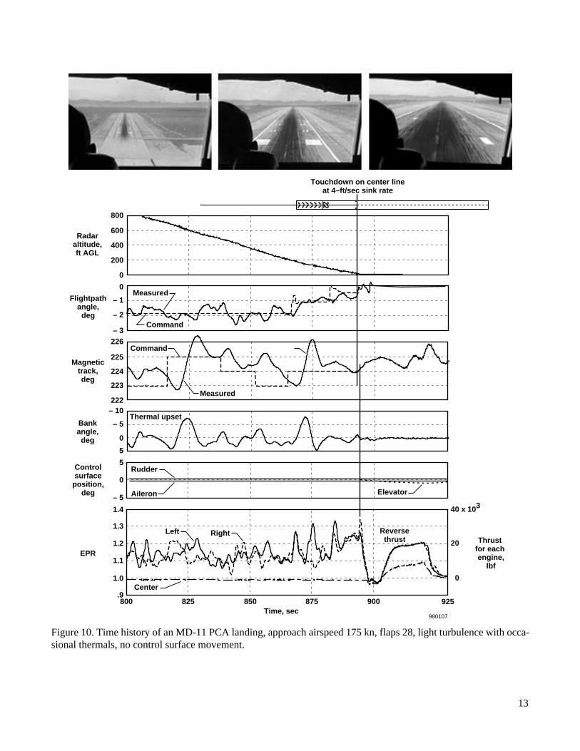
The MD-11 PCA system was implemented bychanging only software in the airplane. The flight con-trol computer contained the PCA control laws and sentcommands to the FADECs over the existing ARINC429 data bus. The FADEC logic was modified to acceptfull-authority (±100–percent) commands rather thanthe usual limit of ±5–percent changes in EPR.
The MD-11 PCA system worked very well. In up-and-away flight, the PCA system performance wascomparable to the normal autopilot, holding headingand flightpath to within 0.5° command. Figure 10shows a time history of an MD-11 PCA landing. Thepilot was using the autopilot control knobs to commandthe PCA system for the landing at Edwards Air ForceBase (California). The center engine was not activelycontrolled and was set near idle thrust. Weather at thetime was characterized by light winds and light turbu-lence with occasional thermal upsets. The pilot madesmall track changes to maintain runway lineup and set
Figure 9. Three-view drawing of the B-747-400 airplane.
Engine 1
Engine 2
Engine 3
Engine 4
39 ft70 ft
105 ft
231 ft
970388
13
Figure 10. Time history of an MD-11 PCA landing, approach airspeed 175 kn, flaps 28, light turbulence with occa-sional thermals, no control surface movement.
Bankangle,deg
Flightpathangle,deg
Command
Measured
Measured
Command
Magnetictrack,deg
Touchdown on center lineat 4–ft/sec sink rate
.9
1.0
1.1
1.2
1.3
1.4
5
– 5
– 5
0
5
222
224
223
225
226
– 10
– 3
– 2
– 1
0
0
400
200
600
800
0
Center
Left Right Reverse thrust
EPR
Time, sec850 900800
Radaraltitude,ft AGL
22
980107
825 875
Controlsurface
position,deg Elevator
Rudder
Aileron
925
Thrust for each engine,
lbf
40 x 103
20
0
Thermal upset

14
the flightpath command at –1.9° for the initial part ofthe approach. Airspeed was 175 kn. At 200 ft aboveground level (AGL), the pilot shallowed the flightpathto –1° and, at 100 ft AGL, to –0.5°. The airplanetouched down smoothly on the center line at a 4–ft/secsink rate 3000 ft from the threshold without either pilotmaking flight control inputs.
Note the upset from a thermal updraft that caused theairplane bank angle to increase to 8° at 100 ft AGL; thePCA track mode corrected this upset without requiringany pilot input. The airplane was stopped using reversethrust and light braking but without any flight controlinputs. The pilot rated the pitch control as excellent andthe lateral control as adequate on this landing. Note theengine thrust changes during the approach. The major-ity of the thrust changes to maintain the pilot’scommanded ground track are differential, although twolarge collective thrust pulses occurred as the flightpathwas shallowed near the ground.
In smooth air, pilots could make good landings ontheir first try using the autopilot knob. In turbulent air,two or three approaches were needed because of thesluggish lateral control response relative to normalflight controls and the corresponding need to learn thelead needed for control corrections. Therefore, thestandard MD-11 ILS-coupled system was used as anouter-loop controller in conjunction with the PCAinner-loop control laws. This pairing permitted goodlandings on a pilot’s first attempt in turbulence levels toa maximum of the “moderate” level and reduced thepilot workload greatly.
A group of 20 pilots, representing industry,commercial airlines, the United States Department ofDefense, NASA, and the Federal Aviation Administra-tion, were invited to fly the MD-11 PCA systemdemonstration. Each pilot completed a brief period ofusing manual TOC followed by coupling the PCA sys-tem and setting up an approach to landing. Most pilotselected to fly an ILS-coupled approach, all of whichwere successful. Some pilots flew a PCA approachusing the PCA control knobs, and most of theseapproaches were also successful. All pilots had highpraise for the PCA system.
12
The B-747-400 Propulsion-Controlled Aircraft System Performance
A PCA system similar to that flown on the MD-11 air-plane was implemented on the B-747-400 high-fidelity
simulation at NASA Ames. The autopilot knobs wereagain used for pilot inputs. Control laws were located ina separate computer, and full-authority EPR trims weresent to the FADECs. An ILS-coupled capability wasadded, and the system was able to operate with anyengine out by simply retarding the correspondingengine on the opposite side to idle power.
Performance of the B-747-400 simulation underPCA control was similar to that of the MD-11 airplane.In up-and-away flight, performance was very good.With some minor gain changes, the PCA system oper-ated over the full flight envelope from sea level to analtitude of 35,000 ft, for the forward and far aft
CGX
,and in upset conditions.
For PCA landings using the autopilot knobs insmooth air, pilots had good success on the first try, sim-ilar to that for the MD-11 airplane. Similar results wereobserved in ILS-coupled approaches. Figure 11 showsan ILS-coupled PCA approach and landing with theright outboard engine off, light turbulence, and a 20-knwind 30° off the nose. The PCA system retarded theleft outboard engine to idle. Bank angle and flightpathwere held within less than 1° of command. The pilotpulled the throttles to idle at 50 ft AGL as ground effectwas entered and touched down smoothly near the run-way centerline. Ten pilots flew the B-747-400 PCAsimulation, including two crew members that had madethe actual DC-10 throttles-only control crash-landing atSioux City, Iowa.
12
SIMPLIFIED PROPULSION-CONTROLLED AIRCRAFT SYSTEMS
The PCA systems flight-tested on the MD-11 andF-15 airplanes and the B-747-400 simulation used full-authority engine control implemented through digitalcommands sent to the digital engine controllers. In atypical transport airplane, software changes would berequired to the engine control computer to accept full-authority commands from the PCA software. For easierimplementation, not having to modify the engine com-puter software would be desirable. Approaches thatwould allow emergency flight control using normallyavailable systems such as autothrottles and thrust trim-ming systems have been studied at NASA Dryden andNASA Ames. These simplified PCA systems, called“PCA Lite,” provide somewhat reduced but possiblystill adequate emergency control capability, depending

15
Figure 11. A B-747-400 full PCA ILS-coupled landing with an engine out, all hydraulics failed, flaps up, lightturbulence, wind from 310° at 20 kn, NASA Ames simulation.
Airspeed,kn
Radaraltitude,ft AGL
Ground track
Magnetictrack,deg
2000
1000
0
240
220
300
290
280
10
0
– 10
0
– 2
– 4
1.5
1.3
1.1
.9
Bankangle,deg
EPR
Flightpathangle,deg
50 100 150Time, sec
200 250
IdleLocalizer capture Glide slope
capture
#4 off#1 idle
980108
Flare Touchdown
Left inboard
Right inboard
Command
Measured

16
on the characteristics of the airplane and the availabil-ity of approach and landing guidance.
Pitch Control
Thrust-only pitch control for many airplanes, includ-ing the B-747-400 and MD-11 airplanes, can beachieved by using the autothrottle system to symmetri-cally drive the throttles using control laws similar to thefull PCA systems. Depending on the autothrottle servosystem response, adequate pitch control capability maybe provided. Pitch commands can be provided by auto-pilot flightpath control thumbwheel or by coupling toan ILS or other landing aid.
Lateral Control
In the absence of normal flight controls, lateral con-trol is generally provided by differential thrust. Thiscontrol may be achieved using the techniques discussedbelow.
Lateral Trim
Operating in the autothrottle mode for pitch control,lateral trim inputs can be manually made by the crew toprovide approximately wings-level flight. The throttlestagger is maintained by the autothrottle system if theidle or maximum thrust stops are not encountered.
Manual Lateral Control
Lateral control can also be performed by manualdifferential throttle manipulation (TOC) by the pilot.With the longitudinal control task being done by theautothrottles, a pilot may be able to provide adequatelateral control for lineup and landing, depending on theairplane characteristics. This method of control shouldbe available on many transport airplanes, althougholder transports may have analog autopilot or auto-throttle systems that would require hardware modifica-tions to perform the pitch PCA control calculations.Although full manual control is not practical (fig. 5), ifthe pitch control problem is handled by the PCA sys-tem, the crew may find it possible to provide lateralcontrol. This “PCA Ultralite” concept was tested on theB-747-400 simulation. Making differential throttleinputs to throttles that were constantly being moved by
the pitch control logic was expected to be difficult;however, a significant problem was not found.
Thrust Trim Lateral Control
“PCA Lite” lateral control can also be provided usingthe existing thrust trim system installed on someairplanes. The authority of the thrust trim is usuallylimited to ±5 percent and may be implemented in termsof EPR or fan speed. One method of commanding lat-eral control is to use the autopilot heading or trackknob. This method of control is available on most air-planes equipped with FADECs, including the MD-11and the B-747-400 airplanes.
“PCA Lite” Results
Simplified “PCA Lite” tests have been conducted onsimulations of the MD-11 and B-747-400 airplanes.Results are described below.
The MD-11 Simulation “PCA Lite” Results
The performance of the MD-11 airplane with a pitchPCA system operating through the autothrottle servowas studied in a linear off-line simulation.11 Perfor-mance was studied with all engines operating and wasjudged to be adequate. Performance was furtherimproved if the center engine was shut down to providea more favorable positive pitching moment with thrustthan was provided with all engines operating.
Simplified means of achieving lateral control on theMD-11 airplane is expected to be less successful thanthat achieved on the B-747-400 airplane because of thefurther inboard location of the wing engines. Figure 2and figure 6 show that the roll-rate parameter for theMD-11 airplane is only one-half that of the B-747-400airplane. The lateral mode of “PCA Lite” on theMD-11 airplane was not tested; however, inspection ofthe differential thrust employed on the PCA landing(fig. 10) exceeds the 0.06 differential EPR that wouldbe available using “PCA Lite.”
The B-747-400 Simulation “PCA Lite” Results
The predominantly collective engine activity on theB-747-400 is primarily caused by the relatively furtheroutboard location of the engines. This observationwas the foundation for the concept of using the existing
17
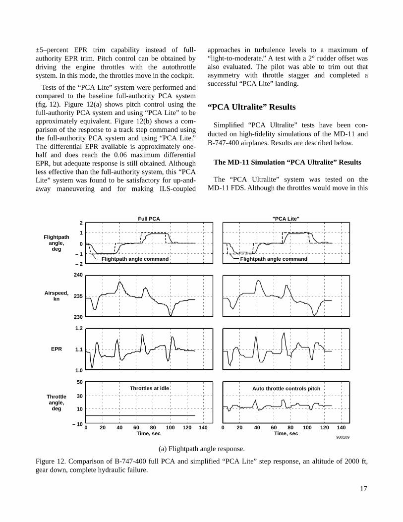
±5–percent EPR trim capability instead of full-authority EPR trim. Pitch control can be obtained bydriving the engine throttles with the autothrottlesystem. In this mode, the throttles move in the cockpit.
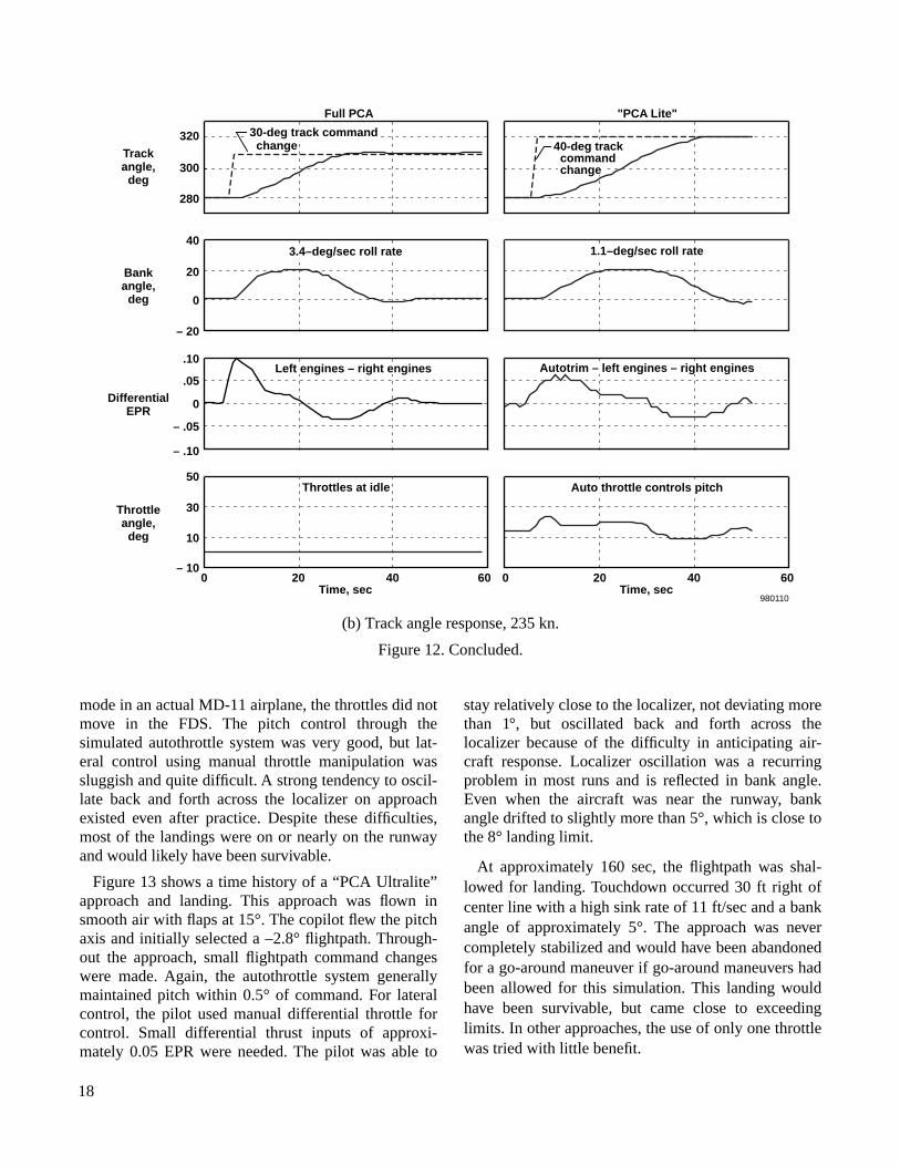
Tests of the “PCA Lite” system were performed andcompared to the baseline full-authority PCA system(fig. 12). Figure 12(a) shows pitch control using thefull-authority PCA system and using “PCA Lite” to beapproximately equivalent. Figure 12(b) shows a com-parison of the response to a track step command usingthe full-authority PCA system and using “PCA Lite.”The differential EPR available is approximately one-half and does reach the 0.06 maximum differentialEPR, but adequate response is still obtained. Althoughless effective than the full-authority system, this “PCALite” system was found to be satisfactory for up-and-away maneuvering and for making ILS-coupled
approaches in turbulence levels to a maximum of“light-to-moderate.” A test with a 2° rudder offset wasalso evaluated. The pilot was able to trim out thatasymmetry with throttle stagger and completed asuccessful “PCA Lite” landing.
“PCA Ultralite” Results
Simplified “PCA Ultralite” tests have been con-ducted on high-fidelity simulations of the MD-11 andB-747-400 airplanes. Results are described below.
The MD-11 Simulation “PCA Ultralite” Results
The “PCA Ultralite” system was tested on theMD-11 FDS. Although the throttles would move in this
(a) Flightpath angle response.
Figure 12. Comparison of B-747-400 full PCA and simplified “PCA Lite” step response, an altitude of 2000 ft,gear down, complete hydraulic failure.
Airspeed,kn
Throttleangle,deg
EPR
0 20 40 60 80Time, sec
100 120 1400– 10
10
30
50
1.0
1.1
1.2
230
235
240
– 2
– 1
0
1
2
20 40 60 80Time, sec
100 120 140
980109
Flightpathangle,deg
"PCA Lite"
Flightpath angle command Flightpath angle command
Auto throttle controls pitchThrottles at idle
Full PCA
18
mode in an actual MD-11 airplane, the throttles did notmove in the FDS. The pitch control through thesimulated autothrottle system was very good, but lat-eral control using manual throttle manipulation wassluggish and quite difficult. A strong tendency to oscil-late back and forth across the localizer on approachexisted even after practice. Despite these difficulties,most of the landings were on or nearly on the runwayand would likely have been survivable.
Figure 13 shows a time history of a “PCA Ultralite”approach and landing. This approach was flown insmooth air with flaps at 15°. The copilot flew the pitchaxis and initially selected a –2.8° flightpath. Through-out the approach, small flightpath command changeswere made. Again, the autothrottle system generallymaintained pitch within 0.5° of command. For lateralcontrol, the pilot used manual differential throttle forcontrol. Small differential thrust inputs of approxi-mately 0.05 EPR were needed. The pilot was able to
stay relatively close to the localizer, not deviating morethan 1°, but oscillated back and forth across thelocalizer because of the difficulty in anticipating air-craft response. Localizer oscillation was a recurringproblem in most runs and is reflected in bank angle.Even when the aircraft was near the runway, bankangle drifted to slightly more than 5°, which is close tothe 8° landing limit.
At approximately 160 sec, the flightpath was shal-lowed for landing. Touchdown occurred 30 ft right ofcenter line with a high sink rate of 11 ft/sec and a bankangle of approximately 5°. The approach was nevercompletely stabilized and would have been abandonedfor a go-around maneuver if go-around maneuvers hadbeen allowed for this simulation. This landing wouldhave been survivable, but came close to exceedinglimits. In other approaches, the use of only one throttlewas tried with little benefit.
(b) Track angle response, 235 kn.
Figure 12. Concluded.
Auto throttle controls pitchThrottles at idle
3.4–deg/sec roll rate 1.1–deg/sec roll rate
Autotrim – left engines – right enginesLeft engines – right engines
40-deg track command change
30-deg track command change
Bankangle,deg
Throttleangle,deg
DifferentialEPR
0 20Time, sec
40 60– 10
10
30
50
– .10
– .05
0
.05
.10
0
– 20
20
40
280
300
320
980110
0 20Time, sec
40 60
Trackangle,deg
"PCA Lite"Full PCA

19
Figure 13. An MD-11 FDS “PCA Ultralite” approach, 15° flaps, no flight control movement.
Go-around maneuvers were possible at altitudes aslow as 100 ft AGL for approaches that were not well–lined up. Rudder offsets to a maximum of 4° could beaccommodated with flaps down, and to a maximumof 3° with flaps up, although these offsets made the
task even more difficult. For rudder offsets greaterthan 4°, depending on the flightpath command,running out of differential throttle authority andtemporarily losing control until the FPA was adjustedwas possible.
Bankangle,deg
0 50 100Time, sec
150 200
EPR
Left
RightThrottlelever angle,
deg
Airspeed,kn
0
– 2
– 4
200
175
150
10
0
– 10
55
45
35
2
0
– 2
1.15
1.10
1.05
1.00
Touchdown 11 ft/sec,30 ft right of center line
980111
Localizerdeviation,
deg
Flightpathangle,deg
Command
Measured
24
Right
Left

20
The B-747-400 Simulation “PCA Ultralite” Results
Several “PCA Ultralite” landings were flown in theB-747-400 simulator at NASA Ames. Initial tests bypilots familiar with PCA characteristics were generallysuccessful. Difficulties became apparent, however,when pilots not familiar with the sluggish and poorlydamped lateral control flew approaches.
Figure 14 shows the first approach by an unfamiliarpilot. As is typical of someone with little PCA experi-ence, the pilot tended to overcontrol the throttlesthroughout the approach. The pilot started with anaggressive bank angle to intercept the localizer, butthen lessened the angle when the airplane was within1000 ft of the localizer. Large differential thrust inputsof approximately 0.07 EPR were often used to try tostay on the localizer. This relatively large differentialthrust resulted in large bank angles and caused the air-craft to oscillate across the localizer.
Near the landing point, the aircraft was slightly offthe right side of the runway. To get back on the runway,the pilot subsequently commanded differential thrustthat caused a large 10° bank angle. Along the way, theaircraft hit hard, with a vertical speed of approximately10 ft/sec, and bounced. The pilot then tried to line upwith the runway by rolling the aircraft 10° in the oppo-site direction. Immediately before the second touch-down, the pilot made a differential thrust input to levelthe wings. The aircraft landed 13 sec after the firsttouchdown, 4500 ft down on the right edge of the run-way, in a 2° bank with a vertical speed of approxi-mately 3 ft/sec. This approach was not very well-stabilized; many large differential thrust inputs weremade trying to keep the aircraft on the center line. Nearthe runway, this overcontrol continued, but the pilotwas able to make a survivable landing.
The “PCA Ultralite” experience on the MD-11 andB-747-400 simulations indicate that more work isneeded to assure safe landings. The use of some sort ofcockpit display to cue the pilot’s manual throttle inputsis being studied.
THRUST-ONLY CONTROL: WING ENGINES FAILED AND LATERAL CENTER-OF-GRAVITY SHIFT
As discussed earlier, the thrust from the engine(s) ononly one wing can be used for flight control if a suitable
way of shifting the center of gravity, CG, toward theoperating engine is available. The capability to shift theCG with fuel transfer and the TOC capability arediscussed below.
Capability to Shift Lateral Center of Gravity
The fuel systems of some airplanes have been studiedto determine the degree of lateral offset that may beobtained. The MD-11 airplane is typical of many trans-port aircraft, having most of the fuel located in thewings and center fuselage. Each wing tank holds42,000 lbm of fuel. The remaining fuel is located in thecenter fuselage tanks and in a small tail tank used toprovide CGX control. Fuel distribution is normallycontrolled by the fuel management system, whichmaintains a programmed CGX schedule, but fuel mayalso be manually transferred among tanks. After take-off, fuel is normally transferred to the tail tank to movethe CGX aft. As discussed in a previous publication,13
the lateral CGY can be shifted a maximum 48 in. Usingthe unmodified fuel system, approximately 16 minwould be required to complete this CGY shift.
A similar situation occurs on other airplanes studied.Four-engine transport aircraft studied include theB-747-400, the CV-990, and the C-17 airplanes.Table 2 shows the maximum CGY offsets available forthese four airplanes and the CGY normalized by wing-span. All four airplanes show a similar capability ofbetween 2.4 and 3.5 percent of total wingspan.
These CGY offsets are also well within the tread of themain landing gear, so no tipover tendency would exist.
Table 2. CGY offsets caused by wing fuel transfer forfour transport airplanes.
AirplaneMaximumdifferentialfuel, lbm
CGY,in.
Overallwing
span, ft
CGY /Span
MD-11 42,000 48 170 0.024
B-747 114,000 85 211 0.033
C-17 90,000 66 165 0.033
CV-990 40,300 51 120 0.035

21
Figure 14. A B-747-400 simulator “PCA Ultralite” approach, glide slope–coupled, 240 kn, 0° flaps, lightturbulence, wind 250° at 20 kn.
010:56
50 100 150 200
0
10
20
30
1.0
.9
1.1
1.2
1.3
– 4000
– 3000
– 2000
– 1000
0
0
500
1000
1500
2000
– 4
– 3
– 2
– 1
0
1
– 20
– 10
0
10
20
Bankangle,
deg
Flightpathangle,
deg
EPR
Altitude,ft AGL
Powerlever angle,
deg
Lateraloffset fromcenter line,
ft
Time, sec
Command
Measured
Touchdown at 6° bank, 10 ft/sec and bounce31 ft right of center line, 547 ft past threshold
980112
2nd touchdown
Engine no.1234
Engine no.1234

22
Thrust-Only Control Capability With Lateral Center of Gravity Shifted
The thrust-only control capability of the MD-11and B-747-400 airplanes have been studied in high-fidelity simulators, previously described. Results arediscussed below.
The MD-11 Simulation Results
Tests were performed in the FDS by turning off theyaw dampers and longitudinal stability augmentationsystems and not touching the flight controls, therebyeliminating any control surface movement. Beginningfrom a trimmed condition, both wing engine throttleswere retarded to idle and fuel transfer was begun. AsCGY increased, the thrust required for wings-levelflight gradually increased.
Figure 15 shows the EPR for the right, or number 3,engine that is required to hold wings level (with theleft, or number 1, engine either at idle or off) as a func-tion of speed at an altitude of 10,000 ft with gear andflaps up. Well within the available CGY offset, wings-level flight on one engine was possible over a range of
speeds from 200 to 300 kn, as shown. As speedincreased, the CGY required for wings-level flightdecreased because as airspeed increased, the yawingmoment from thrust produced less sideslip and hence,less roll. At 300 kn, nearly full thrust on the number 3engine was required to hold the wings level. If CGYwas increased to more than approximately 30 in.,enough thrust would not have existed to prevent a rollto the right. Note that a steady sideslip is required forthis flight condition; therefore, a steady bank angle isrequired to fly a constant heading.
Figure 15 also shows a shaded band that represents athrust value that will result in an FPA of 0°. Conditionsabove the band will result in a climb; conditions belowthe band will result in a descent. Note that this band isfor the MD-11 airplane with the center engine at idle,which approximates a twin-jet airplane. In the MD-11airplane, the center engine thrust could be used to pro-vide an independent means of FPA control.
Open-loop throttle step tests were made. For a wings-level condition, the right engine thrust was increased,sideslip increased to an average of 3°, and the roll rategenerated was –5 deg/sec. As the bank angle passedthrough 40°, the right engine thrust was reduced to idle,
Figure 15. Effect of CGY offset on EPR on the number 3 engine required for wings-level flight, MD-11 FDS, flapsand slats up, gear up, an altitude of approximately 10,000 ft, gross weight approximately 400,000 lbm, centerengine at idle power.
0 105 2015 30 3525 40 45 50
970391CGY offset, in.
.9
1.1
1.0
1.3
1.2
1.5
1.4
1.6
1.7
No. 3engineEPR for
wings level
ClimbDescent
Maximum power
Airspeed,kn
Idle power
≈ 300 ≈ 250 ≈ 210 Single engine
FPA ≈ 0°
Open symbols: left engine idle
Solid symbols: left engine off

23
which caused the sideslip to go to 0° and the roll rate toreverse to approximately 4 deg/sec. In other tests at300 kn, the sideslip required for wings-level flight wasonly 1°, but took nearly full thrust. Maximum roll ratesof 4–5 deg/sec are possible, although depending onspeed, the roll rates may not be equal in each direction.These rates should be adequate for runway lineup inlight turbulence.
Manual throttles-only control in this configurationwas, as expected, extremely difficult, but with somepractice, gross control could be maintained. Controlwas greatly improved with the use of a closed-loopautomatic control system. The control laws from thePCA system that had been flight-tested2 were modifiedslightly, leaving only the right engine thrust being mod-ulated to control track angle, and had feedback parame-ters of roll rate, yaw rate, bank angle, and track. Thelateral control with gains unmodified from the standardMD-11 PCA system provided stable track control,although the control was very sluggish and had a 5°steady-state bias. A 12° commanded track change tookmore than 50 sec to complete. Longitudinal controlusing fuel transfer and the center engine had not beenimplemented, so pitch axis was uncontrolled, thephugoid mode produced FPA oscillations of approxi-mately 2°, and damping was very light.
Later, simulated approaches to a runway were madein the MD-11 FDS. Using the “Track” command knob,runway alignment could be achieved and accuratelymaintained, although a bias of several degrees wasrequired to track the extended runway center line. Noclosed-loop FPA control capability existed in this earlytest, but FPA could likely be controlled sufficiently fora survivable landing using either the center engine orby controlling CGY. Detailed information on theMD-11 airplane has previously been published.13
The B-747-400 Simulation Results
On the B-747-400 airplane, full fuel (114,000 lbm) inone wing and empty tanks in the other wing provides aCGY offset of approximately 83 in. In the simulator,the operator could put full fuel in the right wing tanksand empty the left wing tanks. With all dampers turnedoff, flight controls not used, all fuel in the right wing,and flying at an altitude of 10,000 ft, essentially levelflight is possible with the inboard engine at high powerand the outboard engine at low power and modulated to
maintain the desired bank angle. Manual throttles-onlycontrol (using the outboard engine primarily for rollcontrol and the inboard primarily for pitch control) isadequate to maintain flight, but even gross control isinitially very difficult. After some practice, achieving adegree of heading control is possible, but flightpathcontrol is still extremely difficult.
A preliminary closed-loop control system for theB-747-400 airplane was devised and implemented atNASA Ames and produced stable control, althoughover a restricted flight envelope. Figure 16 shows thedata developed for conditions including a CGY of68.1 in., a speed of 230 kn, and an altitude of 2000 ft,with gear down and flaps up, all hydraulics failed, andthe number 1 and number 2 engines shut down. Thetrim bank angle required for constant heading flightwas 10° with a sideslip of 5.8°, engine number 3 at1.4 EPR, and engine number 4 at 1.3 EPR.
Figure 16(a) shows bank angle commanded from 10°to 15°, then back to 10°, then to 5°, and then back to10°. Engine thrust was modulated to control bank,which was held well. Figure 16(b) shows flightpathcontrol. At time zero, the flightpath command wasreduced to –1°. The thrust of the number 3 andnumber 4 engines was modulated to hold the com-manded flightpath and maintain the commanded head-ing of 286°. Control was also good when the commandwas returned to zero. The performance of this controllaw is surprisingly good and could be combined withCGY control for control over a wide range of flight-paths. More detailed information on the B-747-400CGY offset tests has previously been published.13
ENGINE THRUST RESPONSE AND CONTROL
The response of engines is important when consider-ing thrust for flight control. Typical flight controlsurfaces respond almost instantly, whereas enginethrust response is significantly slower. In all applica-tions studied, however, engine response has been suffi-cient to provide adequate control. The slow response ofthe high-bypass turbofan engines has not been a prob-lem because the dynamics of large airplanes are slowrelative to the engine response. The problem couldbecome more severe than it has been if approaches areflown with no flaps. For fighter aircraft such as the F-15

24
(a) Bank angle step response.
Figure 16. A B-747-400 off-line simulation step response, number 1 and number 2 engines off, complete hydraulicfailure, gross weight 550,000 lbm, lateral center of gravity 68.1 in.
80Time, sec
40 120
980113
1600
20
Bank angle,deg
Command
Angle ofsideslip,
deg
Track angle,deg
Airspeed,kn
Altitude,ft
EPR
10
0
10
Trim bankangle, 10.1°
Trim sideslip,5.8°
Trim airspeed,230 kn
5
0
2050
2000
1950
1.6
1.4
.8
1.0
1.2
310
290
300
280
232
230
231
229
Engine no. 3
Engine no. 4

25
(b) Flightpath angle step response.
Figure 16. Concluded.
80Time, sec
120 160
980114
0 40.8
1.0
1.2
1.4
1.6
286
288
290
292
228
230
232
234
0
10
20
1400
1600
1800
2000
– 1.0
– .5
0
.5
Flightpathangle,deg
Altitude,ft
Airspeed,kn
Bankangle,deg
EPR
Trackangle,deg
Trim bank angle,10.1°
Engine no. 3
Engine no. 4
Trim airspeed,230 kn
Command

26
and F-18 airplanes, airframe dynamics have a higherfrequency than transport airplanes, but the engineresponse is faster and control is still adequate.
Engine thrust control has also not been a problem. Inthe PCA flight tests, the F100 engine in the F-15 air-plane and the PW4460 engines in the MD-11 airplanehad excellent thrust repeatability and resolution. Send-ing digital commands to the engine control systems, aswas done in these PCA tests, provides an almostinfinite resolution, and the ability to command and getvery small thrust changes has been excellent. Using theautothrottle servo motors, as was done in the “PCALite” tests on the B-747-400 airplane, has also beensuccessful, indicating that precise thrust control maynot be required for closed-loop systems.
CONCLUDING REMARKS
The emergency flight control capability of airplanesusing only engine thrust has been studied in flight andin simulations. All airplanes tested have been found tohave the capability for extended flight using enginethrust for flight control. Using throttles-only control,gross control is available and getting to an airport isoften possible, but making a safe landing is not usuallypossible. Using computer-controlled thrust, flight con-trol is greatly improved, and safe landings have beendemonstrated in F-15 and MD-11 airplanes and in sim-ulations of transport airplanes. Thus, a propulsion-controlled aircraft (PCA) system can be used to make asafe landing if all flight control surfaces becomeinoperative.
Simplified PCA systems (“PCA Lite”) using auto-throttle systems and engine trim systems can allow safelandings without the need to modify engine controlcomputers. The further simplified “PCA Ultralite”system is much more difficult to use but can providesurvivable landings with a minimum of airplanechanges required. Simulations have shown that anairplane with all engines out on one wing can be con-trolled using the thrust of the other engines if the lateralcenter of gravity can be shifted toward the operatingengines. Fuel transfer provides a suitable means ofshifting the center of gravity on some airplanes. Enginethrust response and control precision has been adequatein all applications studied.
REFERENCES
1. Burcham, Frank W., Jr., Trindel A. Maine, C.Gordon Fullerton, and Lannie Dean Webb, Develop-ment and Flight Evaluation of an Emergency DigitalFlight Control System Using Only Engine Thrust on anF-15 Airplane, NASA TP-3627, 1996.
2. Burcham, Frank W., Jr. and C. Gordon Fullerton,Controlling Crippled Aircraft—With Throttles, NASATM-104238, 1991.
3. Gilyard, Glenn B., Joseph L. Conley, Jeanette Le,and Frank W. Burcham, Jr., “A Simulation Evaluationof a Four-Engine Jet Transport Using Engine ThrustModulation for Flightpath Control,” AIAA-91-2223,June 1991.
4. Powers, Sheryll Goecke, compiler, An ElectronicWorkshop on the Performance Seeking Control andPropulsion Controlled Aircraft Results of the F-15Highly Integrated Digital Electronic Control FlightResearch Program: Proceedings of the ElectronicWorkshop, NASA TM-104278, 1995.
5. Gerren, Donna S., Design, Analysis, and Controlof a Large Transport Aircraft Utilizing Selective EngineThrust as a Backup System for the Primary Flight Con-trol, NASA CR-186035, 1995.
6. Bull, John, Robert Mah, Gloria Davis, Joe Conley,Gordon Hardy, Jim Gibson, Matthew Blake, Don Bry-ant, and Diane Williams, Piloted Simulation Tests ofPropulsion Control as Backup to Loss of PrimaryFlight Controls for a Mid-Size Jet Transport, NASATM-110374, 1995.
7. Bull, John, Robert Mah, Gordon Hardy, BarrySullivan, Jerry Jones, Diane Williams, Paul Soukup,and Jose Winters, Piloted Simulation Tests of Propul-sion Control as Backup to Loss of Primary Flight Con-trols for a B-747-400 Jet Transport, NASA TM-112191, 1997.
8. Burcham, Frank W., Jr., Trindel A. Maine, John J.Burken, and Drew Pappas, “Development and FlightTest of an Augmented Thrust-Only Flight Control Sys-tem on an MD-11 Transport Airplane,” AIAA-96-3742,1996. Also available as NASA TM-4745, 1996.
9. Kolano, Ed, “Fly by Fire,” Flight International,Dec. 20, 1995, pp. 26–29.
27
10. Burken, John J., Frank W. Burcham, Jr., TrindelA. Maine, John Feather, Steven Goldthorpe, andJeffrey A. Kahler, “Flight Test of a Propulsion-BasedEmergency Control System on the MD-11 AirplaneWith Emphasis on the Lateral Axis,” AIAA-96-3919,July 1996.
11. Burken, John J., Trindel A. Maine, Frank W.Burcham, Jr., and Jeffrey A. Kahler, “LongitudinalEmergency Control System Using Thrust ModulationDemonstrated on an MD-11 Airplane,” AIAA-96-3062,July 1996.
12. Burcham, Frank W., Jr., John J. Burken, TrindelA. Maine, and C. Gordon Fullerton, Development andFlight Test of an Emergency Flight Control SystemUsing Only Engine Thrust on an MD-11 TransportAirplane, NASA TP-97-206217, 1997.
13. Burcham, Frank W., Jr., John Burken, Trindel A.Maine, and John Bull, Emergency Flight Control UsingOnly Engine Thrust and Lateral Center-of-Gravity Off-set: A First Look, NASA TM-4798, 1997.

REPORT DOCUMENTATION PAGE Form ApprovedOMB No. 0704-0188
Public reporting burden for this collection of information is estimated to average 1 hour per response, including the time for reviewing instructions, searching existing data sources, gathering andmaintaining the data needed, and completing and reviewing the collection of information. Send comments regarding this burden estimate or any other aspect of this collection of information,including suggestions for reducing this burden, to Washington Headquarters Services, Directorate for Information Operations and Reports, 1215 Jefferson Davis Highway, Suite 1204, Arlington,VA 22202-4302, and to the Office of Management and Budget, Paperwork Reduction Project (0704-0188), Washington, DC 20503.
1. AGENCY USE ONLY (Leave blank) 2. REPORT DATE 3. REPORT TYPE AND DATES COVERED
4. TITLE AND SUBTITLE 5. FUNDING NUMBERS
6. AUTHOR(S)
8. PERFORMING ORGANIZATION REPORT NUMBER
7. PERFORMING ORGANIZATION NAME(S) AND ADDRESS(ES)
9. SPONSORING/MONITORING AGENCY NAME(S) AND ADDRESS(ES) 10. SPONSORING/MONITORING AGENCY REPORT NUMBER
11. SUPPLEMENTARY NOTES
12a. DISTRIBUTION/AVAILABILITY STATEMENT 12b. DISTRIBUTION CODE
13. ABSTRACT (Maximum 200 words)
14. SUBJECT TERMS 15. NUMBER OF PAGES
16. PRICE CODE
17. SECURITY CLASSIFICATION OF REPORT
18. SECURITY CLASSIFICATION OF THIS PAGE
19. SECURITY CLASSIFICATION OF ABSTRACT
20. LIMITATION OF ABSTRACT
NSN 7540-01-280-5500 Standard Form 298 (Rev. 2-89)Prescribed by ANSI Std. Z39-18298-102
Using Engine Thrust for Emergency Flight Control: MD-11 and B-747Results
WU 522-15-34-00-39-00-IDA
Frank W. Burcham, Jr., Trindel A. Maine, John J. Burken, and John Bull
NASA Dryden Flight Research CenterP.O. Box 273Edwards, California 93523-0273
H-2232
National Aeronautics and Space AdministrationWashington, DC 20546-0001 NASA/TM-1998-206552
With modern digital control systems, using engine thrust for emergency flight control to supplement orreplace failed aircraft normal flight controls has become a practical consideration. The NASA Dryden FlightResearch Center has developed a propulsion-controlled aircraft (PCA) system in which computer-controlledengine thrust provides emergency flight control. An F-15 and an MD-11 airplane have been landed withoutusing any flight control surfaces. Preliminary studies have also been conducted that show that engines on onlyone wing can provide some flight control capability if the lateral center of gravity can be shifted toward theside of the airplane that has the operating engine(s). Simulator tests of several airplanes with no flight controlsurfaces operating and all engines out on the left wing have all shown positive control capability within theavailable range of lateral center-of-gravity offset. Propulsion-controlled aircraft systems that can operatewithout modifications to engine control systems, thus allowing PCA technology to be installed on less capableairplanes or at low cost, are also desirable. Further studies have examined simplified “PCA Lite” and “PCAUltralite” concepts in which thrust control is provided by existing systems such as autothrottles or a combina-tion of existing systems and manual pilot control.
B-747, Emergency control, MD-11, Propulsion control, Throttle-only-controlA03
33
Unclassified Unclassified Unclassified Unlimited
May 1998 Technical Memorandum
Paper presented at the Aviation Safety Issues session of the American Society of Mechanical Engineers 43rdGas Turbine and Aeroengine Technical Congress, Exposition, and Users Symposium, June 2–5, 1998,Stockholm, Sweden
Unclassified—UnlimitedSubject Category 03