Using Double Pressure Heat Recovery Steam Generator ...ijmmm.org/papers/148-TT1005.pdf · exergy...
8
Abstract—Repowering is defined as adding gas turbine unit(s) to steam cycle and using exhaust gases to increase cycle efficiency. Repowering methods are divided into two main ways: full repowering and partial repowering. In this research Be’sat steam power plant in Tehran has been considered as reference steam power plant. This old power plant has been designed by General Electric Corporation with 31.46% efficiency, whereas its current efficiency is 26.81%. In this research by using full repowering a combined cycle have been designed with double pressure heat recovery steam generator equipped with duct burner and through exergy analysis, the functional parameters of the repowered cycle has been studied in the two states of no duct burner and various modes with duct burner (in terms of the fuel flow feed to duct burner). The results showed that thermal and exergy efficiencies for repowered cycle at without duct burner state are 44.39%, 43.06 % respectively and in other states of using burner in general state thermal and exergy efficiencies are higher than reference cycle. It has been shown by results that in repowered cycle combustion chamber in the gas section and HRSG in the steam section have the highest exergy losses. Also The results showed that by using duct burner and increasing the feed fuel, in general state thermal and exergy efficiencies of repowered cycle, decrease and the temperature of the exhaust gas from stack and the exergy losses by it, the generated steam flow and the generation power increases. Index Terms—Efficiency, exergy analysis, full repowering, heat recovery steam generator. I. INTRODUCTION Nowadays energy as one of the most significant issues of human daily life plays remarkable role in all aspects of life. In between power plants generating electricity are major sources of energy generation. Among power plants generating electricity, combined cycle power plants in comparison to gas and steam power plants individually have greater efficiencies; because both sources of generating power are used in the combined cycle power plants. In this research it has been tried to obtain a new combined cycle using full repowering method by considering the design restrictions and efforts have been made to study its weaknesses and strengths by using exergy analysis. Also the effects of various functional states of duct burner on repowered cycle functional parameters such as thermal Manuscript received November 22, 2013; revised March 20, 2014. Vahid Rohani is with the Faculty of Mechanical Engineering, Shahid Rajaee Teacher Training University, Tehran, Iran (e-mail: [email protected]). Mostafa Ahmadi is with the Mechanics Department, Darol Fonoun Faculty, Bojnurd, Iran (e-mail: [email protected]). efficiency, the exergy efficiency of combined cycle, the exergy efficiency of HRSG… through exergy analysis are studied. Repowering includes utilization of exhaust gas of gas turbine(s) set to upgrade steam power plant performance. Repowering methods are classified into two main ways: full repowering and partial repowering.Full repowering is the most common way of repowering. In this method a HRSG and gas turbine(or turbines) are used instead of old boiler. This method is useful for power plants with minimum age of 25 years. Idea of using this this method has been suggested in 1949 for the first time and has been utilized in 1960 [1]. In full repowering various ways can be performed owing to the way considered to omit the feed water heater which include: Omit low pressure feed water heater, Omit low and high pressure feed water heater and not to omit feed water heaters. On the other hand , using additional combustion in HRSG has been widely developed for the purpose of controlling the temperature and the generated steam flow in the mode of lowering the load of gas turbine and/or offset the ambient changes. The burners that generate this additional combustion in boilers are called duct burners. One of the old steam power plants in Iran is Be’sat power plant. Its old age has been cuased an efficiency reduction since its operation time [2]. Modeling steam power plant cycles have been done according to the presented technical documents by General Electric Corporation. In this research after modeling steam turbines, their specifications have been considered in new concerning full repowering scenarios; feed water heaters have been omitted because of power plant old age. Design of HRSGs and gas turbine cycle has been done proportional to steam turbines in the reference cycle. Used HRSG is double pressure with reheat equipped with duct burner. Finally it has been tried to analyze functional parameters by exergy analysis. EES thermodynamic software has been used for modeling new cycle. In the past some researches have been conducted in the fields of repowering, exergy analysis of combined cycles and using duct burners. For example, Hosseinalipour S. M. et al. (2011) have done full repowering for a steam power plant; they have optimized economical and technical specifications of the new cycle [3]. Mehrpanahi A. et al. (2011) have investigated various methods of repowering on country electricity generating power plants to measure its effect on electricity generating costs [4]. Gambini M. and Guizzi G. L. (1989) have done full repowering for a steam power to reach higher ability of generating power [5]. In a similar research Brander J. A. and Chase D. L. (1992) have investigated practical restrictions of a steam cycle full repowering [6]. Using another method of repowering Mehrpanahi A. and Hoseinalipoor S. M. (2011) have Using Double Pressure Heat Recovery Steam Generator Equipped with Duct Burner for Full Repowering a Steam Power Plant and Its Analysis by Exergy Method V. Rohani and M. Ahmadi International Journal of Materials, Mechanics and Manufacturing, Vol. 2, No. 4, November 2014 309 DOI: 10.7763/IJMMM.2014.V2.148
Transcript of Using Double Pressure Heat Recovery Steam Generator ...ijmmm.org/papers/148-TT1005.pdf · exergy...
Abstract—Repowering is defined as adding gas turbine unit(s)
to steam cycle and using exhaust gases to increase cycle
efficiency. Repowering methods are divided into two main ways:
full repowering and partial repowering. In this research Be’sat
steam power plant in Tehran has been considered as reference
steam power plant. This old power plant has been designed by
General Electric Corporation with 31.46% efficiency, whereas
its current efficiency is 26.81%. In this research by using full
repowering a combined cycle have been designed with double
pressure heat recovery steam generator equipped with duct
burner and through exergy analysis, the functional parameters
of the repowered cycle has been studied in the two states of no
duct burner and various modes with duct burner (in terms of
the fuel flow feed to duct burner). The results showed that
thermal and exergy efficiencies for repowered cycle at without
duct burner state are 44.39%, 43.06 % respectively and in
other states of using burner in general state thermal and exergy
efficiencies are higher than reference cycle. It has been shown
by results that in repowered cycle combustion chamber in the
gas section and HRSG in the steam section have the highest
exergy losses. Also The results showed that by using duct
burner and increasing the feed fuel, in general state thermal
and exergy efficiencies of repowered cycle, decrease and the
temperature of the exhaust gas from stack and the exergy losses
by it, the generated steam flow and the generation power
increases.
Index Terms—Efficiency, exergy analysis, full repowering,
heat recovery steam generator.
I. INTRODUCTION
Nowadays energy as one of the most significant issues of
human daily life plays remarkable role in all aspects of life. In
between power plants generating electricity are major
sources of energy generation. Among power plants
generating electricity, combined cycle power plants in
comparison to gas and steam power plants individually have
greater efficiencies; because both sources of generating
power are used in the combined cycle power plants. In this
research it has been tried to obtain a new combined cycle
using full repowering method by considering the design
restrictions and efforts have been made to study its
weaknesses and strengths by using exergy analysis. Also the
effects of various functional states of duct burner on
repowered cycle functional parameters such as thermal
Manuscript received November 22, 2013; revised March 20, 2014.
Vahid Rohani is with the Faculty of Mechanical Engineering, Shahid
Rajaee Teacher Training University, Tehran, Iran (e-mail: [email protected]).
Mostafa Ahmadi is with the Mechanics Department, Darol Fonoun
Faculty, Bojnurd, Iran (e-mail: [email protected]).
efficiency, the exergy efficiency of combined cycle, the
exergy efficiency of HRSG… through exergy analysis are
studied. Repowering includes utilization of exhaust gas of
gas turbine(s) set to upgrade steam power plant performance.
Repowering methods are classified into two main ways: full
repowering and partial repowering.Full repowering is the
most common way of repowering. In this method a HRSG
and gas turbine(or turbines) are used instead of old boiler.
This method is useful for power plants with minimum age of
25 years. Idea of using this this method has been suggested in
1949 for the first time and has been utilized in 1960 [1]. In
full repowering various ways can be performed owing to the
way considered to omit the feed water heater which include:
Omit low pressure feed water heater, Omit low and high
pressure feed water heater and not to omit feed water heaters.
On the other hand , using additional combustion in HRSG
has been widely developed for the purpose of controlling the
temperature and the generated steam flow in the mode of
lowering the load of gas turbine and/or offset the ambient
changes. The burners that generate this additional
combustion in boilers are called duct burners. One of the old
steam power plants in Iran is Be’sat power plant. Its old age
has been cuased an efficiency reduction since its operation
time [2]. Modeling steam power plant cycles have been done
according to the presented technical documents by General
Electric Corporation. In this research after modeling steam
turbines, their specifications have been considered in new
concerning full repowering scenarios; feed water heaters
have been omitted because of power plant old age. Design of
HRSGs and gas turbine cycle has been done proportional to
steam turbines in the reference cycle. Used HRSG is double
pressure with reheat equipped with duct burner. Finally it has
been tried to analyze functional parameters by exergy
analysis. EES thermodynamic software has been used for
modeling new cycle. In the past some researches have been
conducted in the fields of repowering, exergy analysis of
combined cycles and using duct burners. For example,
Hosseinalipour S. M. et al. (2011) have done full repowering
for a steam power plant; they have optimized economical and
technical specifications of the new cycle [3]. Mehrpanahi A.
et al. (2011) have investigated various methods of
repowering on country electricity generating power plants to
measure its effect on electricity generating costs [4]. Gambini
M. and Guizzi G. L. (1989) have done full repowering for a
steam power to reach higher ability of generating power [5].
In a similar research Brander J. A. and Chase D. L. (1992)
have investigated practical restrictions of a steam cycle full
repowering [6]. Using another method of repowering
Mehrpanahi A. and Hoseinalipoor S. M. (2011) have
Using Double Pressure Heat Recovery Steam Generator
Equipped with Duct Burner for Full Repowering a Steam
Power Plant and Its Analysis by Exergy Method
V. Rohani and M. Ahmadi
International Journal of Materials, Mechanics and Manufacturing, Vol. 2, No. 4, November 2014
309DOI: 10.7763/IJMMM.2014.V2.148
optimized parallel feed water heat recovery for Shahid
Rajaei power plant in Tehran to decrease electricity
generating costs [7]. In another research Tajik Mansouri M.
and Ahmadi P. (2012) have evaluated and compared three
types of HRSG used in combined cycles to analyze effect of
vapor pressure level enhancement in power and efficiency
increase and reduction in combined cycles exergy destruction
[8]. Bassily M. (2008) has been investigated power and
efficiency enhancement using a HRSG triple pressure. They
utilize duct burner and reheating to increase generating
power [9]. Franco A. and Russo A. (2002) believed that by
optimizing effective parameters on HRSG and using different
HRSGs along with decreasing pinch temperature and
increasing levels of heat absorption in the boiler, higher
efficiency and power can be obtainable [10]. Backlund J. C.
and Batshon A. introduced the advantages and disadvantages
of duct burner and studied using irregular fuels such as the
gas produced from sewers, steel plants furnaces,
decomposition of solid urban wastes…in the duct burner [11].
Dincer I. and Ahmadi P. designed a combined cycle
equipped with duct burner and by using the genetic
algorithm, optimized the target functions such as price of
consumed fuel, production poor [12].
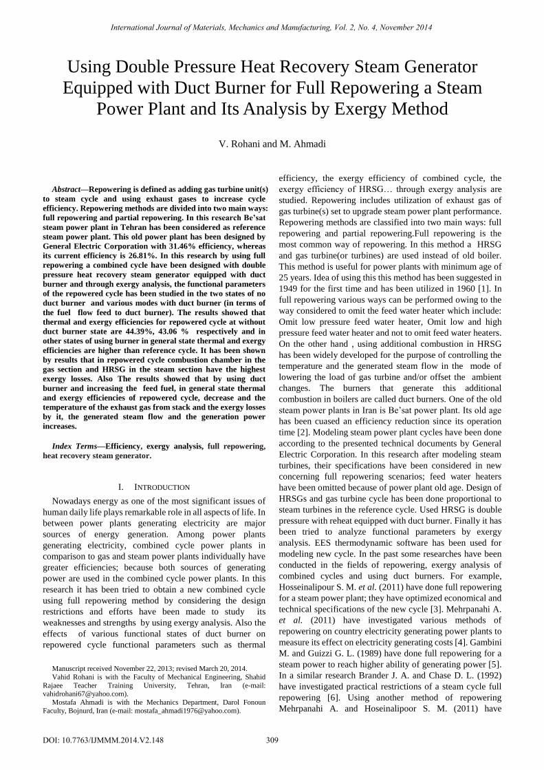
Fig. 1. Schematic diagram of a gas turbine cycle.
II. REFERENCE CYCLE SPECIFICATIONS
Be’sat power plant is an old steam power plant designed by
General Electric corporation with 31.46% efficiency whereas
its current real efficiency is 26.81%. Efficiency reduction has
been caused by power plant old lifetime and exhaustion [2].
A v94.2 gas turbine made by Simense Company with power
of 160 MW has been used in the gas section of the power
plant. Steam cycle has a heat boiler, two high pressure
turbines, two intermedial turbines and two low pressure
turbines. Also a condenser and a set of feed water reheaters
can be seen in this cycle. Part of steam turbines exhaust gas is
extracted to the feed waters and reheats the boiler feed water.
Fig. 1. Thermodynamic properties of steam/water in different
parts of the reference cycle has been shown in Table I.
III. REPOWERING OPERATION PROCEDURE
1) Gas turbine and steam turbines have been considered
exactly according to the reference cycle.
2) Size of used HRSG and gas turbine have been
considered with regard to maximum arrival steam to the first
high pressure turbine in the thermodynamic conditions of the
reference cycle (turbine inlet pressure and temperature of the
reference cycle) [3].
3) Restrictions of condenser in receiving the amount of
steams fed by present cycle must be carefully considered. In
designing the condenser, the amount of feeding stem flow is
taken as mCond=73.05 Kg/S; however, this amount could be
increased up to 45% [3].
4) Since power plant has a wet cooling tower condenser
pressure usual range is 0.068 to 0.136 bar[13]. In this
research condenser operational pressure which is equal to the
condenser pressure in the reference cycle, is considered as a
constant and equal to 0.72 bar.
5) A double pressure with reheat HRSG has been used in
repowered cycle to utilize the exegy of exhaust gas of gas
turbine set perfectly to produce steam.
TABLE I: WATER/STEAM PROPERTIES OF BE’SAT POWER PLANT
point Temperature
(K)
Pressure
(bar)
Entropy
(KJ/Kg 0K)
Mass
Flow (Kg/S)
Enthalpy
(KJ/Kg)
1 581.7 96.61 3.334 91.94 1392.5
2 578.0 91.78 5.665 91.94 2739.0
3 783.1 87.20 6.708 91.94 3415.0 4 663.0 33.60 6.826 84.58 3200.6
5 580.4 17.23 6.873 78.58 3047.5
6 476.7 6.50 6.941 73.05 2854.9 7 392.8 1.68 7.211 68.09 2707.0
8 365.6 0.77 7.090 62.67 2533.2
9 315.8 0.08 7.321 62.67 2298.8 10 663.0 33.60 6.826 7.36 3200.6
11 580.4 17.23 6.873 6.00 3047.5
12 476.7 6.50 6.941 5.33 2854.9 13 403.0 2.68 7.001 4.96 2708.6
14 365.6 0.77 7.090 5.42 2533.2
15 635.7 31.26 6.766 7.36 3141.5 16 558.9 16.02 6.825 6.00 3001.5
17 466.5 6.05 6.930 5.33 2834.6
18 400.6 2.50 6.897 4.96 2654.4 19 365.6 0.72 6.979 5.42 2533.2
20 316.2 0.72 0.612 73.05 180.0
21 316.2 6.43 0.610 73.05 180.0 22 358.3 6.24 1.132 73.05 355.9
23 393.6 6.05 1.527 73.05 503.9 24 435.3 108.08 1.952 91.94 690.8
25 471.2 104.84 2.270 91.94 834.2
26 315.8 0.08 0.727 10.38 216.4 27 324.9 0.14 0.725 10.38 216.4
28 363.3 0.71 1.250 4.96 398.0
29 368.3 0.85 1.250 4.96 398.0 30 432.4 6.05 2.061 13.36 726.9
31 444.4 8.16 2.059 13.36 726.9
32 455.6 16.02 2.330 7.36 852.4 33 473.2 18.62 2.330 7.36 852.4
34 508.2 101.69 2.641 91.94 1015.1
6) The steam produced by HRSG should be able to change
in accordance with the cycle conditions and the condenser
limitations; for that reason, in studying the designed cycle, a
value named K has been used. This number is a coefficient
for the steam flow that arrived into condenser and is in fact
the amount of steam generated by boiler with respect to the
performance conditions of duct burner and repowered cycle.
7) In repowered cycle, high pressure steam arrived into the
first high pressure steam turbine and low pressure steam
arrived into the intermedial pressure turbine. The discharging
steam of the high pressure turbine entry into re-heater
complex and after absorption of the heat once again at
HRSG, it returns to the Intermedial turbines (Fig. 3).
8) Pressure generated by water pumps in the transfer
pipelines will face some losses, so to approach real
International Journal of Materials, Mechanics and Manufacturing, Vol. 2, No. 4, November 2014
310
conditions some pressure losses are considered such as 3.5%
in economizer pipes, 3% in superheater, 5% in reheater and
5.5% in water/steam pipes. There is no pressure loss in
evaporator [14]. Also it should be mentioned that 5% of gas
energy has been considered as energy losses related to the gas
in the boiler [3].
9) In case of lower temperature of the gas discharge from
boiler than the acid dew point of the gas mix, the water vapor
content is distilled on the pre-heater and economizer pipes
and in their compositions with other combustion products
such as CO2, they produce corrosive acids that damages the
pipes. In order to prevent this, in boilers design, the T=361°K
is taken as the acid dew point of gas mixture to save the
temperature of the gas that exit from boilers from lowering
that point [8]-[12].
10) Natural gas is used as a fuel in both duct burner and gas
turbine combustion chamber.
11) In repowered cycle, the keep pinch temperature
difference not less than 10 °K; because if this temperature
goes lower, we will need more heat transfer levels [15].
12) All processes are taken in steady state and steady flow.
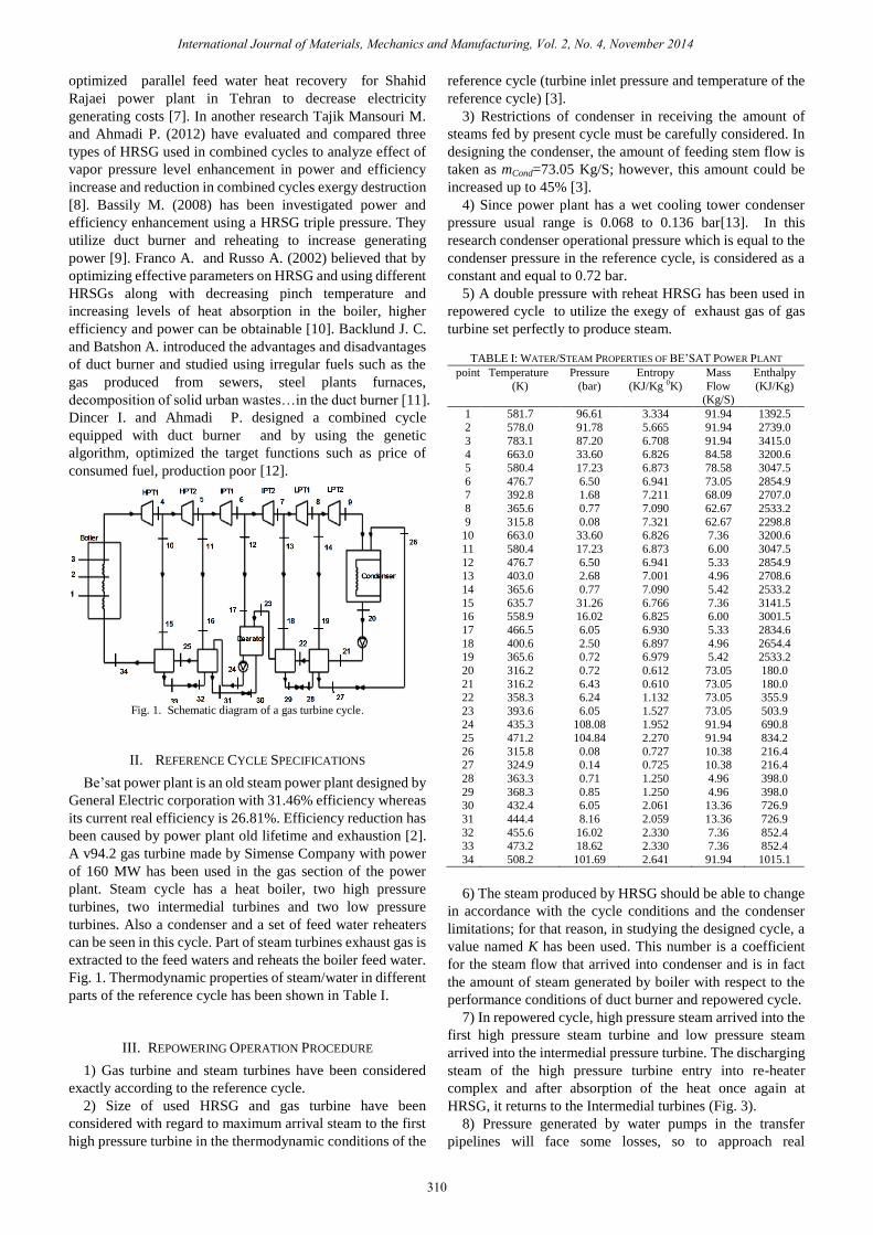
IV. ENERGY ANALYSIS
Fig. 2. Schematic diagram of a gas turbine cycle.
Energy balance has been used for control volume in steady
state conditions to model cycles [9]. Set of gas turbines have
been considered according to the simple brayton cycle as can
be seen in Fig. 2.
A. Air Compressor [8]
1
1[1 ( 1)]
a
aT T rcB A
AC
(1)
. ,
W m C T TB Aa p a (2)
Cp,a has been defined as a function of temperature [12]:2 3 4
3.8371 9.4537 5.49031 7.9298( ) 1.04841 ( ) ( ) ( ) ( ), 4 7 10 14
10 10 10 10
T T T TC Tp a (3)
B. Combustion Chamber [9]
(1 )m h m LHV m h m LHVa B f g C AC f (4)
C. Gas Turbine [2]
( ),W m C T TGT g p g D C (6)
1
[1 (1 ( ) )]
aPC a
T TD C GTPD
(5)
W W Wnet GT AC (7)
m m mg f a (8)
(1 ) ( ) ( ), 3 4 , 2 1
WGTma
AF C T T C T TP g P g
(9)
2 36.99703 2.7129 1.22442
( ) 0.991615 ( ) ( ) ( ), 4 7 1010 10 10
T T TC Tp g
(10)
Constant values of gases in the products of combustion
0.2944 KJ/Kg 0K, losses due to combustion chamber 3%, low
heat value of the fuel equals to methane heat value which is
50000 KJ/Kg, combustion chamber efficiency has been
considered 97%, gas specific heat capacity and air used have
been computed as a function of temperature.
D. Duct Burner [12]
Amount of the fuel fed to duct burner is taken as a variable
and in order to prevent the overheating the super heater pipes,
the amount of fed fuel should be less than 1 Kg/S [9].
,
. ., , , , , ,
,1 CCh DB
m C m LHV m C Tg pg f DB g in HRSG p g in HRSG E
m LHVf DB
(11)
E. HRSG
In design of HRSG approach temperature difference have
been considered 15o
K. Using energy equation for
steam/water and gas in HRSG various sections following
equations can be written [3]-[16]:
1) Steam/water
_, , , , ,T T DELTA Tgt out pre eva pre eva pre pinch (12)
_, , , , ,T T DELTA Tgt out hp eva hp eva hp pinch (13)
_, , , , ,T T DELTA Tgt out lp eva lp eva lp pinch (14)
2) Gas
E to F
. .( )(1 ) ( ), , , 12 11 16 15m C T T E m h h h hg in HRSG p gt E F Loss hp (15)
F to G
. .( )(1 ) ( ), , , 11 10m C T T E m h hg in HRSG p gt F G Loss hp (16)
G to H
. .( )(1 ) ( ) ( ), , , 10 5 7 5m C T T E m h h m h hg in HRSG p gt G H Loss hp Lp (17)
H to I
. .( )(1 ) ( )( ), , , 5 4m C T T E m m h hg in HRSG p gt H I Loss hp Lp (18)
I to J
. .( )(1 ) ( )( ), , , 4 2m C T T E m m h hg in HRSG p gt J I Loss hp Lp (19)
J to k
. .( )(1 ) ( )( ), , , 2 1m C T T E m m h hg in HRSG p gt J K Loss hp Lp (20)
The amount of emerged steam is defined as follows:
.m K mSteam cond (21)
F. Steam Turbine
Power generated by steam turbines is as follows [3]:
( ), , ,W m h hStagesST ST in ST in ST out
(22)
thermal efficiency of the cycle is obtainable by following
International Journal of Materials, Mechanics and Manufacturing, Vol. 2, No. 4, November 2014
311
relation [3]:
,
W W WGT AC SteamCC
Qin CC
(23)
V. EXERGY ANALYSIS
Exergy analysis is defined on the basis of first and second
laws of thermodynamic. Exergy analysis is a tool to analyze
and determine system inefficiencies. Exergy is defined as
follows [16]: If a system has n subset with temperature T and
pressure P and also mole fractions as y=1,2,…,n, exergy is
defined as the maximum obtainable theoretical work in
process from state(P, T, Yi) to dead state of (P0, T0, Yi).It
should be mentioned that dead state (P0, T0, Yi) is a system
state which there is perfect balance between system and its
environment with temperature T0 and pressure P0 in this state
is considered as the reference state. Exergy is divided into
four sections (four kinds of exergy can be mentioned as): 1)
physical exergy, 2) chemical exergy, 3) kinematic exergy, 4)
potential exergy. In most exergy analysis just physical and
chemical exergies are considered. In the current analysis
kinematic and potential exergies have been ignored. Using
first and second laws of thermodynamics, general exergy
equation can be written as follows [10]-[16]:
E m e m e E IQ i i e e Q (24)
e is unit exergy and is exergy losses.
0(1 )
TE QQ i
Ti
(25)
E WW (26)
Chemical and physical exergy of gas mixture:
[ ]0 00
chch Ein ne X e RT X LnX Gi ii i i
(27)
( ) ( )0 0 0
phE h h T S S (28)
GE is related to the amount of Gibbs free energy which can
be ignored in low pressures of the gas mixture.
0 index is used to show reference state and T0 is the
reference environment temperature [16]. Relation (29) and
(30) are defined for fuel with CXHy Composotions and fuel
exergy respectively.
1.033 0.01690.0698y
x x
(29)
ef
LHVf
(30)
Amount of fuel exergy is shown by . Combined cycle
exergy and HRSG efficiencies are defined as follows [10]:
W W WGT AC SteamCC
E f
(31)
, ,
,
, , , ,
E ESteam out water in
ex HRSGE Eflue gas in flue gas out
(32)
VI. REPOWERED CYCLE
Using reference cycle and its related information a double
pressure combined cycle are considered for full repowering.
In these cycle natural gas has been used as fuel which its
composition is presented in Table II [2]-[8].
TABLE II: VOLUME FRACTION OF THE NATURAL GAS COMPONENT
Component of natural gas Volume fraction (%)
Methane 98.57
Ethane 0.63
Propane 0.1 Butane 0.05
Pentane 0.04
Nitrogen 0.6 Carbon dioxide 0.01
Used turbine specifications are presented in the Table III.
Combustion chamber exhaust gas composition has been
shown in Table IV [2].
TABLE III: SOME CHARACTERISTIC DATA OF GAS TURBINE
Parameter Unit Amount
Fuel flow(LHV) MW 50 Pressure ratio - 15.98
Gas turbine inlet temperature K 1353
Gas turbine outlet temperature K 793.2 Power output MW 160
TABLE IV: COMBUSTION PRODUCT MOLE COMPOSITION.
Component Molar composition (%)
N2 74.463
O2 12.623
CO2 3.715 H2O 8.303
Ar 0.897
Gas properties in different points of the repowered cycle
are shown in Table V.
TABLE V: STREAM CHARACTERISTICS OF THE GAS TURBINE CYCLE
Point Temperature
(K)
Pressure
(bar)
Mass
Flow (Kg/S)
Specific
exergy (KJ/Kg)
Exergy
(MW)
A 298.15 1.013 544.9 0 0
B 733.2 16.19 544.9 417.3 227.3 C 1353 15.71 555.4 1013.6 562.8
D 793.2 1.013 555.4 235.2 130.6
Reference environment in this modeling is air with
thermodynamic conditions of P=1.013 bar, T=298.15 0k and
its molar composition is presented in Table VI [17]. Basic
and reference data to model combined cycle is listed
according to the reference cycle properties in Table VII.
TABLE VI: REFERENCE ENVIRONMENT MODEL OF AIR
Air components Molar fraction (%)
N2 75.67
O2 20.35
H2O 3.03 CO2 0.0345
CO 0.0007
SO2 0.0002 H2 0.00005
Others 0.91455
Others 0.91455
TABLE VII: INPUT DATA FOR THERMODYNAMIC MODELING OF THE
CYCLES
Parameter Unit Amount
HP inlet temp. K 783.1
HP inlet press Bar 87.21
LP inlet temp. K 580 (a) LP inlet press. bar 10.27
Condenser press. bar 0.72 a=Hot reheat temperature.
International Journal of Materials, Mechanics and Manufacturing, Vol. 2, No. 4, November 2014
312
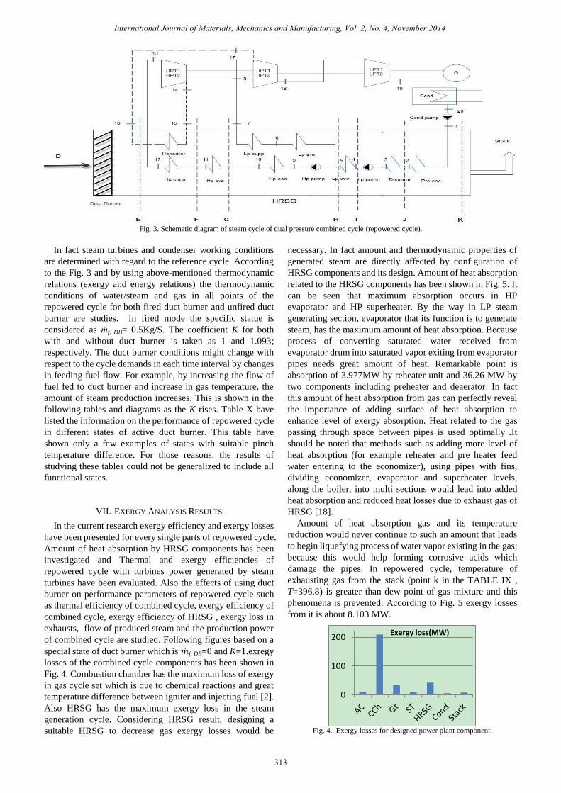
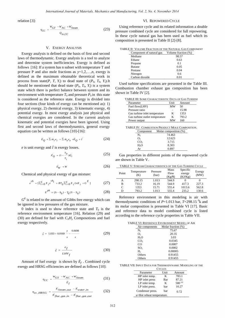
Fig. 3. Schematic diagram of steam cycle of dual pressure combined cycle (repowered cycle).
In fact steam turbines and condenser working conditions
are determined with regard to the reference cycle. According
to the Fig. 3 and by using above-mentioned thermodynamic
relations (exergy and energy relations) the thermodynamic
conditions of water/steam and gas in all points of the
repowered cycle for both fired duct burner and unfired duct
burner are studies. In fired mode the specific statue is
considered as ṁf, DB= 0.5Kg/S. The coefficient K for both
with and without duct burner is taken as 1 and 1.093;
respectively. The duct burner conditions might change with
respect to the cycle demands in each time interval by changes
in feeding fuel flow. For example, by increasing the flow of
fuel fed to duct burner and increase in gas temperature, the
amount of steam production increases. This is shown in the
following tables and diagrams as the K rises. Table X have
listed the information on the performance of repowered cycle
in different states of active duct burner. This table have
shown only a few examples of states with suitable pinch
temperature difference. For those reasons, the results of
studying these tables could not be generalized to include all
functional states.
VII. EXERGY ANALYSIS RESULTS
In the current research exergy efficiency and exergy losses
have been presented for every single parts of repowered cycle.
Amount of heat absorption by HRSG components has been
investigated and Thermal and exergy efficiencies of
repowered cycle with turbines power generated by steam
turbines have been evaluated. Also the effects of using duct
burner on performance parameters of repowered cycle such
as thermal efficiency of combined cycle, exergy efficiency of
combined cycle, exergy efficiency of HRSG , exergy loss in
exhausts, flow of produced steam and the production power
of combined cycle are studied. Following figures based on a
special state of duct burner which is f, DB=0 and K=1.exregy
losses of the combined cycle components has been shown in
Fig. 4. Combustion chamber has the maximum loss of exergy
in gas cycle set which is due to chemical reactions and great
temperature difference between igniter and injecting fuel [2].
Also HRSG has the maximum exergy loss in the steam
generation cycle. Considering HRSG result, designing a
suitable HRSG to decrease gas exergy losses would be
necessary. In fact amount and thermodynamic properties of
generated steam are directly affected by configuration of
HRSG components and its design. Amount of heat absorption
related to the HRSG components has been shown in Fig. 5. It
can be seen that maximum absorption occurs in HP
evaporator and HP superheater. By the way in LP steam
generating section, evaporator that its function is to generate
steam, has the maximum amount of heat absorption. Because
process of converting saturated water received from
evaporator drum into saturated vapor exiting from evaporator
pipes needs great amount of heat. Remarkable point is
absorption of 3.977MW by reheater unit and 36.26 MW by
two components including preheater and deaerator. In fact
this amount of heat absorption from gas can perfectly reveal
the importance of adding surface of heat absorption to
enhance level of exergy absorption. Heat related to the gas
passing through space between pipes is used optimally .It
should be noted that methods such as adding more level of
heat absorption (for example reheater and pre heater feed
water entering to the economizer), using pipes with fins,
dividing economizer, evaporator and superheater levels,
along the boiler, into multi sections would lead into added
heat absorption and reduced heat losses due to exhaust gas of
HRSG [18].
Amount of heat absorption gas and its temperature
reduction would never continue to such an amount that leads
to begin liquefying process of water vapor existing in the gas;
because this would help forming corrosive acids which
damage the pipes. In repowered cycle, temperature of
exhausting gas from the stack (point k in the TABLE IX ,
T=396.8) is greater than dew point of gas mixture and this
phenomena is prevented. According to Fig. 5 exergy losses
from it is about 8.103 MW.
Fig. 4. Exergy losses for designed power plant component.
0
100
200 Exergy loss(MW)
International Journal of Materials, Mechanics and Manufacturing, Vol. 2, No. 4, November 2014
313
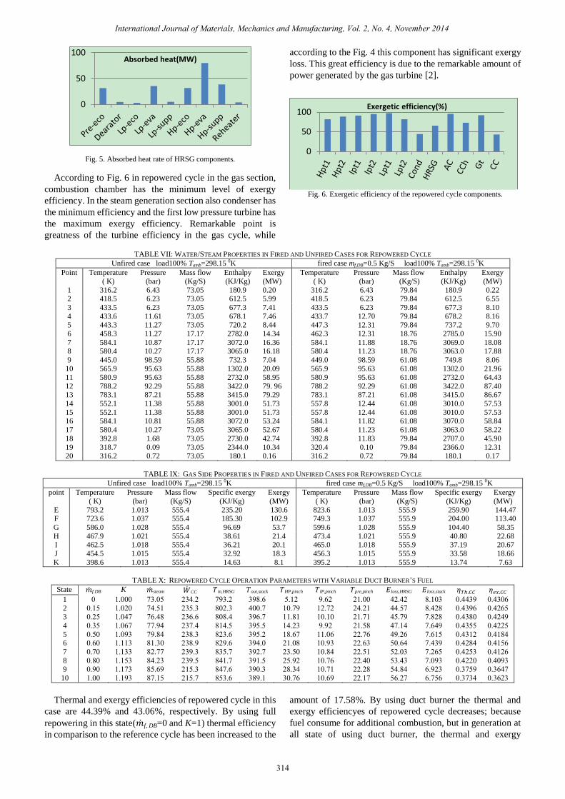
Fig. 5. Absorbed heat rate of HRSG components.
According to Fig. 6 in repowered cycle in the gas section,
combustion chamber has the minimum level of exergy
efficiency. In the steam generation section also condenser has
the minimum efficiency and the first low pressure turbine has
the maximum exergy efficiency. Remarkable point is
greatness of the turbine efficiency in the gas cycle, while
according to the Fig. 4 this component has significant exergy
loss. This great efficiency is due to the remarkable amount of
power generated by the gas turbine [2].
Fig. 6. Exergetic efficiency of the repowered cycle components.
TABLE VII: WATER/STEAM PROPERTIES IN FIRED AND UNFIRED CASES FOR REPOWERED CYCLE
Unfired case load100% Tamb=298.15 0K fired case mf,DB=0.5 Kg/S load100% Tamb=298.15 0K
Point
Temperature
( K)
Pressure
(bar)
Mass flow
(Kg/S)
Enthalpy
(KJ/Kg)
Exergy
(MW)
Temperature
( K)
Pressure
(bar)
Mass flow
(Kg/S)
Enthalpy
(KJ/Kg)
Exergy
(MW)
1 316.2 6.43 73.05 180.9 0.20 316.2 6.43 79.84 180.9 0.22 2 418.5 6.23 73.05 612.5 5.99 418.5 6.23 79.84 612.5 6.55
3 433.5 6.23 73.05 677.3 7.41 433.5 6.23 79.84 677.3 8.10
4 433.6 11.61 73.05 678.1 7.46 433.7 12.70 79.84 678.2 8.16 5 443.3 11.27 73.05 720.2 8.44 447.3 12.31 79.84 737.2 9.70
6 458.3 11.27 17.17 2782.0 14.34 462.3 12.31 18.76 2785.0 15.90
7 584.1 10.87 17.17 3072.0 16.36 584.1 11.88 18.76 3069.0 18.08 8 580.4 10.27 17.17 3065.0 16.18 580.4 11.23 18.76 3063.0 17.88
9 445.0 98.59 55.88 732.3 7.04 449.0 98.59 61.08 749.8 8.06
10 565.9 95.63 55.88 1302.0 20.09 565.9 95.63 61.08 1302.0 21.96 11 580.9 95.63 55.88 2732.0 58.95 580.9 95.63 61.08 2732.0 64.43
12 788.2 92.29 55.88 3422.0 79. 96 788.2 92.29 61.08 3422.0 87.40 13 783.1 87.21 55.88 3415.0 79.29 783.1 87.21 61.08 3415.0 86.67
14 552.1 11.38 55.88 3001.0 51.73 557.8 12.44 61.08 3010.0 57.53
15 552.1 11.38 55.88 3001.0 51.73 557.8 12.44 61.08 3010.0 57.53 16 584.1 10.81 55.88 3072.0 53.24 584.1 11.82 61.08 3070.0 58.84
17 580.4 10.27 73.05 3065.0 52.67 580.4 11.23 61.08 3063.0 58.22
18 392.8 1.68 73.05 2730.0 42.74 392.8 11.83 79.84 2707.0 45.90 19 318.7 0.09 73.05 2344.0 10.34 320.4 0.10 79.84 2366.0 12.31
20 316.2 0.72 73.05 180.1 0.16 316.2 0.72 79.84 180.1 0.17
TABLE IX: GAS SIDE PROPERTIES IN FIRED AND UNFIRED CASES FOR REPOWERED CYCLE
Unfired case load100% Tamb=298.15 0K fired case mf,DB=0.5 Kg/S load100% Tamb=298.15 0K
point
Temperature
( K)
Pressure
(bar)
Mass flow
(Kg/S)
Specific exergy
(KJ/Kg)
Exergy
(MW)
Temperature
( K)
Pressure
(bar)
Mass flow
(Kg/S)
Specific exergy
(KJ/Kg)
Exergy
(MW)
E 793.2 1.013 555.4 235.20 130.6 823.6 1.013 555.9 259.90 144.47 F 723.6 1.037 555.4 185.30 102.9 749.3 1.037 555.9 204.00 113.40
G 586.0 1.028 555.4 96.69 53.7 599.6 1.028 555.9 104.40 58.35
H 467.9 1.021 555.4 38.61 21.4 473.4 1.021 555.9 40.80 22.68 I 462.5 1.018 555.4 36.21 20.1 465.0 1.018 555.9 37.19 20.67
J 454.5 1.015 555.4 32.92 18.3 456.3 1.015 555.9 33.58 18.66
K 398.6 1.013 555.4 14.63 8.1 395.2 1.013 555.9 13.74 7.63
TABLE X: REPOWERED CYCLE OPERATION PARAMETERS WITH VARIABLE DUCT BURNER’S FUEL
State f.DB K steam CC in,HRSG out,stack HP,pinch lP,pinch pre,pinch loss,HRSG loss,stack
1 0 1.000 50.07 204.2 5.0.2 0.8.3 7.12 ..32 21.00 42.42 8.100 0.440. 0.4003
2 0.17 1.020 54.71 207.0 802.0 400.5 10.5. 12.52 24.21 44.75 8.428 0.40.3 0.4237 3 0.27 1.045 53.48 203.3 808.4 0.3.5 11.81 10.10 21.51 47.5. 5.828 0.4080 0.424.
4 0.07 1.035 55..4 205.4 814.7 0.7.7 14.20 ...2 21.78 45.14 5.34. 0.4077 0.4227
5 0.70 1.0.0 5..84 208.0 820.3 0.7.2 18.35 11.03 22.53 4..23 5.317 0.4012 0.4184 6 0.30 1.110 81.00 208.. 82..3 0.4.0 21.08 10..0 22.30 70.34 5.40. 0.4284 0.4173
7 0.50 1.100 82.55 20..0 807.5 0.2.5 20.70 10.84 22.71 72.00 5.237 0.4270 0.4123
8 0.80 1.170 84.20 20..7 841.5 0.1.7 27..2 10.53 22.40 70.40 5.0.0 0.4220 0.40.0 9 0..0 1.150 87.3. 217.0 845.3 0.0.0 28.04 10.51 22.28 74.84 3..20 0.057. 0.0345
10 1.00 1.1.0 85.17 217.5 870.3 08..1 00.53 10.3. 22.15 73.25 3.573 0.0504 0.0320
Thermal and exergy efficiencies of repowered cycle in this
case are 44.39% and 43.06%, respectively. By using full
repowering in this state( f, DB=0 and K=1) thermal efficiency
in comparison to the reference cycle has been increased to the
amount of 17.58%. By using duct burner the thermal and
exergy efficiencyes of repowered cycle decreases; because
fuel consume for additional combustion, but in generation at
all state of using duct burner, the thermal and exergy
0
50
100Absorbed heat(MW)
0
50
100Exergetic efficiency(%)
International Journal of Materials, Mechanics and Manufacturing, Vol. 2, No. 4, November 2014
314
efficiencies of repowered cycle is greater than reference
cycle (Fig. 8 & Fig. 9). With respect to Table X. it could be
seen that in combined cycle, by using duct burner, due to
increase in the entrance gas temperature to HRSG, the
amount of steam production increases. In steam turbines, this
leads to increase in production power. On the other hand, the
exergy increase of the gas from duct burner is absorbed by the
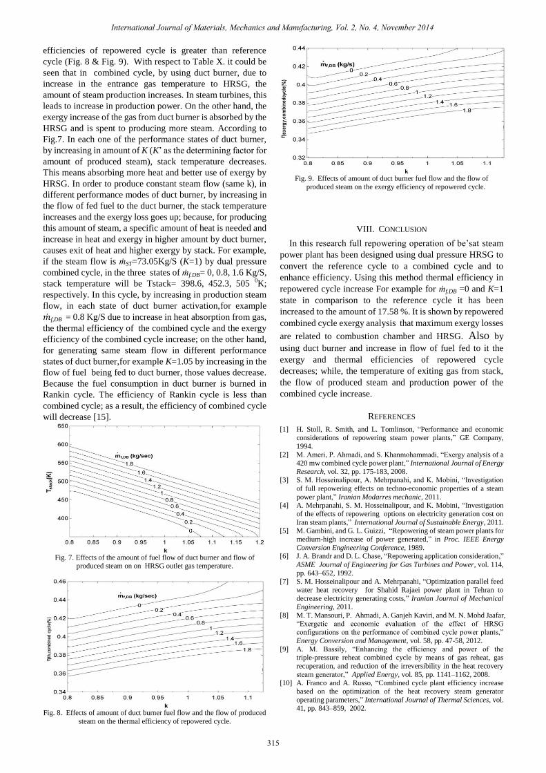
HRSG and is spent to producing more steam. According to
Fig.7. In each one of the performance states of duct burner,
by increasing in amount of K (K’ as the determining factor for
amount of produced steam), stack temperature decreases.
This means absorbing more heat and better use of exergy by
HRSG. In order to produce constant steam flow (same k), in
different performance modes of duct burner, by increasing in
the flow of fed fuel to the duct burner, the stack temperature
increases and the exergy loss goes up; because, for producing
this amount of steam, a specific amount of heat is needed and
increase in heat and exergy in higher amount by duct burner,
causes exit of heat and higher exergy by stack. For example,
if the steam flow is ṁST=73.05Kg/S (K=1) by dual pressure
combined cycle, in the three states of ṁf.DB= 0, 0.8, 1.6 Kg/S,
stack temperature will be Tstack= 398.6, 452.3, 505 0K;
respectively. In this cycle, by increasing in production steam
flow, in each state of duct burner activation,for example
f,DB = 0.8 Kg/S due to increase in heat absorption from gas,
the thermal efficiency of the combined cycle and the exergy
efficiency of the combined cycle increase; on the other hand,
for generating same steam flow in different performance
states of duct burner,for example K=1.05 by increasing in the
flow of fuel being fed to duct burner, those values decrease.
Because the fuel consumption in duct burner is burned in
Rankin cycle. The efficiency of Rankin cycle is less than
combined cycle; as a result, the efficiency of combined cycle
will decrease [15].
Fig. 7. Effects of the amount of fuel flow of duct burner and flow of
produced steam on on HRSG outlet gas temperature.
Fig. 8. Effects of amount of duct burner fuel flow and the flow of produced
steam on the thermal efficiency of repowered cycle.
Fig. 9. Effects of amount of duct burner fuel flow and the flow of
produced steam on the exergy efficiency of repowered cycle.
VIII. CONCLUSION
In this research full repowering operation of be’sat steam
power plant has been designed using dual pressure HRSG to
convert the reference cycle to a combined cycle and to
enhance efficiency. Using this method thermal efficiency in
repowered cycle increase For example for ṁf.DB =0 and K=1
state in comparison to the reference cycle it has been
increased to the amount of 17.58 %. It is shown by repowered
combined cycle exergy analysis that maximum exergy losses
are related to combustion chamber and HRSG. Also by
using duct burner and increase in flow of fuel fed to it the
exergy and thermal efficiencies of repowered cycle
decreases; while, the temperature of exiting gas from stack,
the flow of produced steam and production power of the
combined cycle increase.
REFERENCES
[1] H. Stoll, R. Smith, and L. Tomlinson, “Performance and economic
considerations of repowering steam power plants,” GE Company,
1994. [2] M. Ameri, P. Ahmadi, and S. Khanmohammadi, “Exergy analysis of a
420 mw combined cycle power plant,” International Journal of Energy
Research, vol. 32, pp. 175-183, 2008. [3] S. M. Hosseinalipour, A. Mehrpanahi, and K. Mobini, “Investigation
of full repowering effects on techno-economic properties of a steam
power plant,” Iranian Modarres mechanic, 2011. [4] A. Mehrpanahi, S. M. Hosseinalipour, and K. Mobini, “Investigation
of the effects of repowering options on electricity generation cost on
Iran steam plants,” International Journal of Sustainable Energy, 2011. [5] M. Gambini, and G. L. Guizzi, “Repowering of steam power plants for
medium-high increase of power generated,” in Proc. IEEE Energy
Conversion Engineering Conference, 1989. [6] J. A. Brandr and D. L. Chase, “Repowering application consideration,”
ASME Journal of Engineering for Gas Turbines and Power, vol. 114,
pp. 643–652, 1992. [7] S. M. Hosseinalipour and A. Mehrpanahi, “Optimization parallel feed
water heat recovery for Shahid Rajaei power plant in Tehran to
decrease electricity generating costs,” Iranian Journal of Mechanical Engineering, 2011.
[8] M. T. Mansouri, P. Ahmadi, A. Ganjeh Kaviri, and M. N. Mohd Jaafar,
“Exergetic and economic evaluation of the effect of HRSG configurations on the performance of combined cycle power plants,”
Energy Conversion and Management, vol. 58, pp. 47-58, 2012.
[9] A. M. Bassily, “Enhancing the efficiency and power of the triple-pressure reheat combined cycle by means of gas reheat, gas
recuperation, and reduction of the irreversibility in the heat recovery
steam generator,” Applied Energy, vol. 85, pp. 1141–1162, 2008. [10] A. Franco and A. Russo, “Combined cycle plant efficiency increase
based on the optimization of the heat recovery steam generator
operating parameters,” International Journal of Thermal Sciences, vol. 41, pp. 843–859, 2002.
International Journal of Materials, Mechanics and Manufacturing, Vol. 2, No. 4, November 2014
315

[11] A. Batshon and J. C. Backlund, “Alternative fuel for supplementary
firing add value and flexibility to combined cycle and cogeneration
plants,” International journal of Power Generation, 2001. [12] P. Ahmadi and I. Dincer, “Thermodynamic analysis and
thermoeconomic optimization of a dual pressure combined cycle
power plant with a supplementary firing unit,” Energy Conversation Management, vol. 5, pp. 296–308, 2011
[13] R. Mottaghianet, “SPRD steam power plant design,” Power Plant
Department of Matn Company, Tehran, Iran, 1999. [14] J. M. Escosa and L. M. Romeo, “Optimizing CO2 avoided cost by
means of repowering,” Applied Energy, vol. 86, pp. 2351–2358, 2009.
[15] J. C. Backlund and J. Froeming, “Thermal and economical analysis of supplementary firing large combined cycle plants,” Coen Company.
[16] N. R. Kumar, K. R. Krishna, and A. V. S. R. Raju, “Thermodynamic
analysis of heat recovery steam generator in combined cycle power plant,” Thermal Science, vol. 11, pp. 143-156, 2007.
[17] T. Sirinivas, A. Gupta, and B. V. Reddy, “Thermodynamic modeling
and optimization of multi-pressure heat recovery steam generator in combined power cycle,” Journal of SciInd, vol. 67, pp. 827–834, 2008.
[18] H. Sharifi, Heat Recovery Steam Generators, Tehran: Pendar Pars
Publishers, 2011, ch. 3.
Vahid Rohani was born in Bojnurd, Iran in 1988.
received his B.S. in 2010 and M.S. in 2013 in the
Department of Mechanical Engineering at Shahid Rajaei Teacher Training University of Tehran. He is now
working at Ministry of Education of Iran as a teacher. His
current research interests are energy management and power plant designing.
Mostafa Ahmadi was born in Bojnurd, Iran in 1976.
received his B.S. in 2000 and M.S. in 2013 in the Department of Mechanical Engineering at Shahid Rajaei
Teacher Training University of Tehran. He is now with
Mechanics Department, Darol Fonoun Faculty, Bojnurd, Iran. His current research interests are enhancing
efficiency of thermodynamic cycles, optimization of
engine functional parameters and fluid mechanic.
International Journal of Materials, Mechanics and Manufacturing, Vol. 2, No. 4, November 2014
316