Ontology Design Patterns for the Semantic Business Processes

Using an Ontology to Suggest Software Design Patterns
Integration
Dania Harb, Cédric Bouhours, Hervé Leblanc
IRIT – MACAO
Université Paul Sabatier
118 Route de Narbonne
F-31062 TOULOUSE CEDEX 9
{harb, bouhours, leblanc}@irit.fr
Abstract. To give a consistent and more valuable feature on models, we
propose that model-driven processes should be able to reuse the expert
knowledge generally expressed in terms of patterns. In order to formalize and
use them, some design pattern ontologies have been developed. To share them
on the Web they have been implemented using the OWL language. They can be
easily interrogated with dedicated query languages. Our work has consisted in
extending a design pattern intent ontology with “alternative model” and “strong
points” concepts, which partially refers “anti-patterns”. We validate this
approach in tooling a step of a design review activity, we have proposed. This
activity, directed by design patterns, is adapted to a model driven process, for
the need to improve object-oriented architecture quality.
Keywords: OWL, SPARQL, Software Design Pattern, Design Review
Activity, MDE, MDA
1 Introduction
The emergent MDE community, aiming at giving a productive feature on models, has
proposed model-driven process development. However, to obtain guarantees on
model relevance at the end of each activity, these processes should promote the reuse
of the knowledge of experts generally expressed in terms of analysis [1], design [2] or
architectural [3] patterns approved by the community. Given the existence of “code
review” activities [4] in some development processes, we have specified a “design
review” activity [5] directed by design patterns and oriented to model quality. In this
activity, we propose to parse models to find fragments substitutable with software
design patterns and to replace them if the intent of the designer matches with the
intent of the pattern and if the architectural qualities of the pattern are needed. Our
activity is situated after the design stage, and its purpose is to urge and to help the
designer to integrate design pattern in his design.
Thanks to their Design Pattern Intent Ontology (DPIO), Kampffmeyer et al. [6]
have developed a wizard enabling designers to efficiently retrieve software design
patterns applicable for their design problems, during the design stage. Our approach
2 Dania Harb, Cédric Bouhours, Hervé Leblanc
has not the same timing. It is situated after the design stage, and it verifies if there is
no known bad design practices in a model. So, the designer is not in need of
identifying design problems, it is the activity which finds the lacks in his models and
suggests design patterns integrations instead. However, the DPIO [6] is an interesting
start point for the formalization of our concepts because it links software design
pattern to some problem concepts. So, in reusing this ontology backwards (from the
pattern to the design problems), and in adding our concepts, we are able to establish a
dialog with the designer.
In this paper, after presenting the design review activity, we explain how we have
reused and extended the DPIO [6]. We illustrate the execution of our activity on a
“file system management” example.
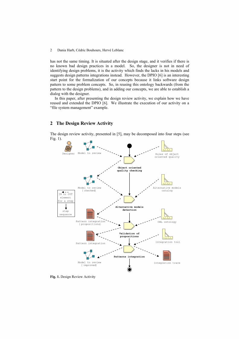
2 The Design Review Activity
The design review activity, presented in [5], may be decomposed into four steps (see
Fig. 1).
Pattern integration
[propositions]
Rules of object
oriented quality
Model to review
Designer
Model to review
[checked]
Model to review
[improved]
Alternative models
catalog
Integration tool
Object oriented
quality checking
Alternative models
detection
Patterns integration
Validation of
propositions
Pattern integration
Integration trace
OWL ontology
step
sequence
IN or OUT
element
for a step
Fig. 1. Design Review Activity
Using an Ontology to Suggest Software Design Patterns Integration 3
In order to work with models in a “sufficient” quality, the first step checks good
basic object-oriented design practices.
When the model to review is checked in a “sufficient” quality state, the second step
consists in an automatic research of model fragments which are candidate to a
substitution with a pattern. This research is based on structural similarities detection
with “alternative models”. An “alternative model” is a model which solves
inadequately the same problem as a pattern [5]. That means there is a better solution
to solve this problem. Our work hypothesis is that a software design pattern is the
best solution for a given design problem. According to the taxonomy proposed by
Chikofsky and Cross [8], our detection technique can be connected to a
redocumentation technique as to permit model restructuring. Our “alternative
models” catalog is presented in [9], with the experiments used to constitute it.
Each “alternative model” detected in the model represents propositions of
fragments substitutable with a design pattern. Since we need the designer opinion in
the third step, our ontology will help him determine if his intent matches with the
suggested pattern intent and whether the propositions are needed in the model to
review.
With the designer authorization, the last step consists in integrating the validated
propositions into the model. This integration is done thanks to an automatic model
refactoring.
3 Reusing and extending an existing ontology
In order to improve the design of object oriented models, our work relies on detecting
all instances of alternative models in UML design models and substituting them, if
necessary, with appropriate design patterns. Each class of the instances detected is
connected in the same manner as the classes of the alternative model. So, since the
detection is only structural, the instances detected must be checked by the designer
before any substitution with a pattern. Therefore, after the detection step, propositions
of patterns integration consist of sets of model fragments representing a possible
substitution. These sets may be large where some fragments may not be relevant with
a substitution. So, to help the designer in filtering the fragments, we need an ontology
that formalizes intent of design patterns (is the substitution have a sense?) and our
characterizations of “alternative models” in terms of quality features (is the effort of
the substitution balanced by improved architectural qualities?).
For this purpose, we choose OWL, the Web Ontology Language [10], to import an
existing ontology on design patterns intent and extend it by adding our knowledge on
“alternative models”. We validated our new knowledge base using a specific query
language to interrogate it and filter out the pertinent information.

4 Dania Harb, Cédric Bouhours, Hervé Leblanc
3.1 Requirements
Our catalogue is composed with “alternative models”, introduced in Section 2, and
their characterization. We have constituted our catalog in asking students to solve
some design problems. These problems were simply solvable with designs patterns,
but, as the students chosen have no knowledge on design patterns, they solve the
problems without using design patterns. In following our work hypothesis, their
solutions were not the best solution for the problem, and so, the models produced had
some design defects. The characterization of these defects consists in a valuation of
the “strong points” of the pattern. “Strong points” are criteria of object-oriented
architecture or software engineering quality, partially deduced from the
“consequences” section of the GoF [2] catalogue and from our study on the design
defects of “alternative models”. As pattern injection may alter some object-oriented
metrics [11], “strong points” allow us to compute dedicated pattern metrics to classify
the “alternative models” and to help the estimation of the pertinence of pattern
injection in a design model. Each “alternative model” perturbs the “strong points” of
its associated pattern.
Since we need to formally describe design patterns, “alternative models” and
“strong points” in a machine readable format, we start with the DPIO ontology. These
concepts must be constructed in a way that allows querying based on the “alternative
model” detected.
Intent: Compose objects into tree structures to represent part-whole hierarchies.
Composite lets clients treat individual objects and compositions of objects uniformly.
Applicability: Use the Composite pattern when:
you want to represent part-whole hierarchies of objects.
you want clients to be able to ignore the difference between compositions of
objects and individual objects. Clients will treat all objects in the composite
structure uniformly.
Structure:
Component
Leaf
+children*
Composite
Strong points: 1 Decoupling and extensibility
1.1 Maximal factorization of the composition
1.2 Addition or removal of a Leaf does not need code modification
1.3 Addition or removal of a Composite does not need code modification
2 Uniform processing
2.1 Uniform processing on operations of composed object
2.2 Uniform processing on composition managing
2.3 Unique access point for the client
Using an Ontology to Suggest Software Design Patterns Integration 5
Fig. 2. Composite Pattern and its “Strong Points”
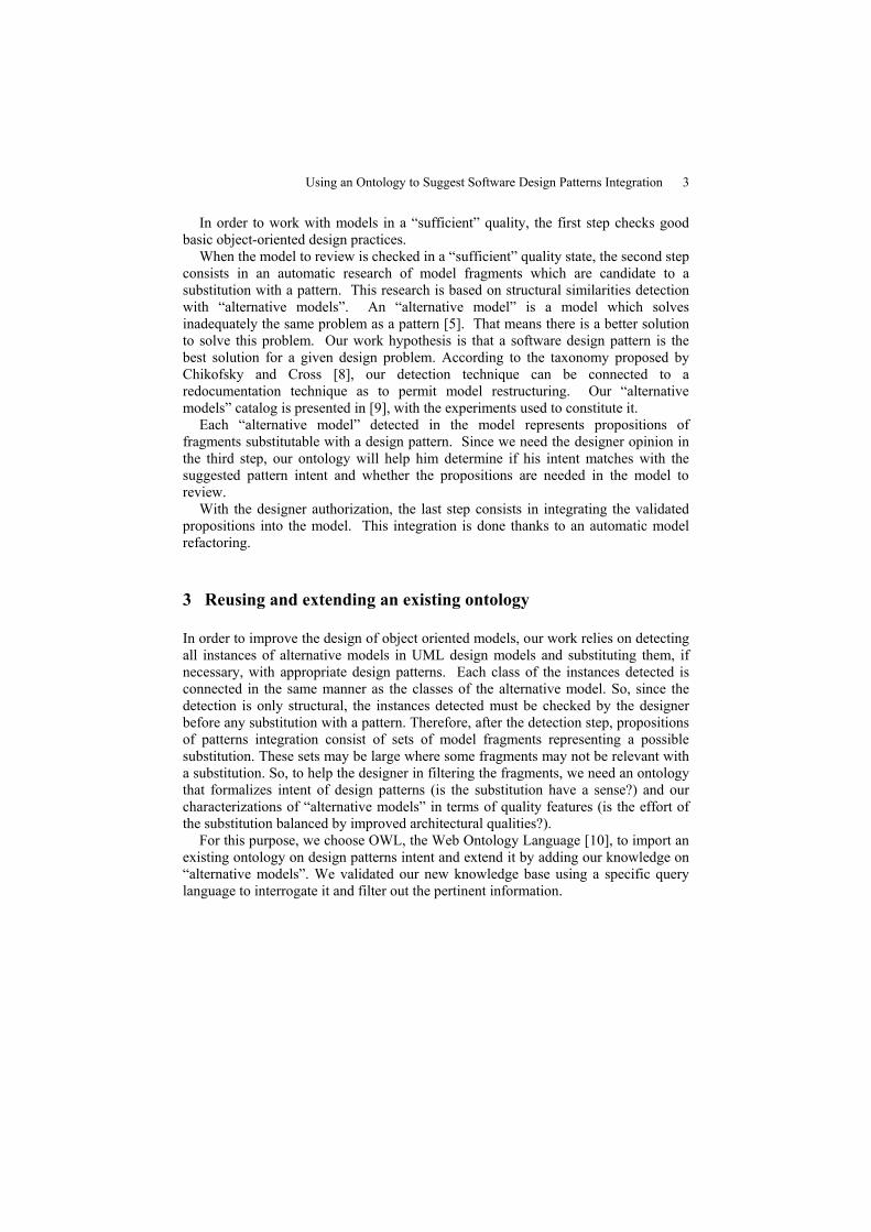
In Fig. 2, we present one of the GoF patterns, named Composite. The intent, the
applicability and the structure are provided directly from the GoF book while the
“strong points” are deduced from our experiments by comparing solutions to specific
design problem implemented by the Composite pattern and its “alternative models”.
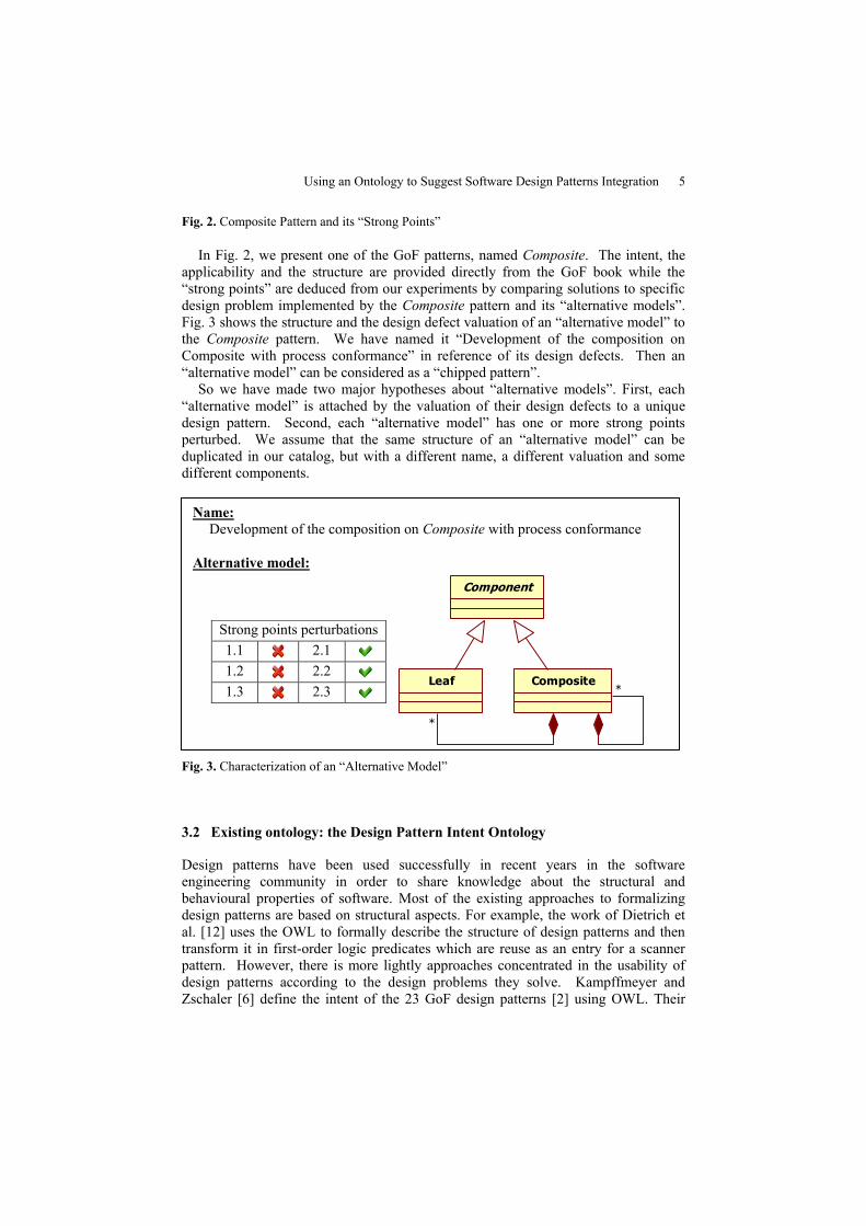
Fig. 3 shows the structure and the design defect valuation of an “alternative model” to
the Composite pattern. We have named it “Development of the composition on
Composite with process conformance” in reference of its design defects. Then an
“alternative model” can be considered as a “chipped pattern”.
So we have made two major hypotheses about “alternative models”. First, each
“alternative model” is attached by the valuation of their design defects to a unique
design pattern. Second, each “alternative model” has one or more strong points
perturbed. We assume that the same structure of an “alternative model” can be
duplicated in our catalog, but with a different name, a different valuation and some
different components.
Fig. 3. Characterization of an “Alternative Model”
3.2 Existing ontology: the Design Pattern Intent Ontology
Design patterns have been used successfully in recent years in the software
engineering community in order to share knowledge about the structural and
behavioural properties of software. Most of the existing approaches to formalizing
design patterns are based on structural aspects. For example, the work of Dietrich et
al. [12] uses the OWL to formally describe the structure of design patterns and then
transform it in first-order logic predicates which are reuse as an entry for a scanner
pattern. However, there is more lightly approaches concentrated in the usability of
design patterns according to the design problems they solve. Kampffmeyer and
Zschaler [6] define the intent of the 23 GoF design patterns [2] using OWL. Their
Name:
Development of the composition on Composite with process conformance
Alternative model:
Component
CompositeLeaf*
*
Strong points perturbations
1.1 2.1
1.2 2.2
1.3 2.3

6 Dania Harb, Cédric Bouhours, Hervé Leblanc
work was based on the work of Tichy [13], who developed a catalogue of more than
hundred design patterns classified according to the problems patterns solve.
The core structure of the DPIO, provided from the paper [6], is presented in Fig. 4
by UML classes and associations. Kampffmeyer and Zschaler chose to represent their
ontology with UML diagram because they consider that is easily to understand. To
read the diagram, they indicate: “The relations between DesignPattern, DPProblem
and ProblemConcept classes are depicted using UML-notations. UML classes
symbolize OWL classes and UML associations symbolize OWL object properties.
Each DesignPattern is a solution to one or more design pattern problem DPProblem.
The association between them indicates an object property isSolutionTo which is an
inverse property of isSolvedBy. DPProblem is defined that is the root node for more
specific problems. The association class Constrains indicates an OWL object property
that can be specialized also by subproperties. DPProblem is a set of classes that
describe a problem by constraining a ProblemConcept”. The DPIO contains the
vocabulary for describing the intent of design patterns.
Fig. 4. Graphical overview of the core structure of the DPIO
All the 23 GoF patterns inherit from the DesignPattern class. DPProblem and
ProblemConcept are the root classes of the other hierarchies.
Based on the work of [6], and instead of finding the design pattern for a given
problem, we retrieve the intent of a design pattern. It is much like reversing the query
to get the pertinent data from the same ontology. So we can benefit from their existing
work and their published ontology.
3.3 Method and Results
Now to determine the scope of our new ontology, there are kinds of questions called
“competency questions” the ontology should be able to answer [14]. Our work could
be defined in 3 steps: first, when an “alternative model” is detected, we need to
interrogate our knowledge base to know which design pattern could replace it.
Second, we will verify with the designer if his “alternative model” detected has a
similar intent as the corresponding design pattern. Last, in this case, we will show him

Using an Ontology to Suggest Software Design Patterns Integration 7
the lack in his model by displaying the perturbed “strong points”. Then, if the
designer finds the need to improve his model, his fragment will be substituted with
the design pattern. Therefore, the three competency questions are as follow:
1. Which design pattern could replace a given “alternative model”?
2. What is the intent of the corresponding design pattern?
3. Which are the “strong points” perturbed using this “alternative model”?
In designing the structure of the new ontology, we took into consideration all the
possible relations between the classes in the DPIO model and the classes we want to
add:
1. Each”alternative model” could be replaced by one and only one Design
Pattern. But a Design Pattern will replace one to many “alternative
models”.
2. An “alternative model” perturbs at least one “strong point” of the Design
Pattern that can replace it.
From this analysis, we extend the DPIO by adding our new concepts.
Fig. 5. Graphical overview of the structure of the extended ontology
Fig. 5 represents the new structure of the extended ontology. Based on this
structure and the relations between classes, we extended the existing ontology with
OWL classes and properties as follow:
1. Two new OWL classes:
a. AlternativeModel: the root class of all “alternative models”. They
are grouped by the design pattern that could replace them. For
example, we find six “alternative models” for the Composite
pattern. They inherit all from the Composite_AM class (Fig. 6).
They have the name of their super class followed by their
numeration in the catalogue.
b. StrongPoint: the root class of all the “strong points”. They are
attached to a design pattern. For example, we find two main
“strong points” for the Composite pattern: Composite_Rule_1
and Composite_Rule_2 (Fig. 6); each one of them was précised
by three sub features. They have the name of their super class
followed by their numeration in the catalogue.

8 Dania Harb, Cédric Bouhours, Hervé Leblanc
2. Four new OWL properties:
a. isReplacedBy: links an AlternativeModel to his corresponding
DesignPattern.
b. Replace: the inverse of isReplacedBy.
c. Perturbes: links an AlternativeModel to the valuation of the
corresponding pattern “strong points” (StrongPoint).
d. hasRule: links a DesignPattern class to one of its StrongPoint.
Fig. 6 shows a detailed structure of the extended base concerning the Composite
pattern. The “alternative model” presented in Fig. 3 perturbs the three subfeatures of
the first “strong point” of the Composite pattern that concerned in the Decoupling and
extensibility. More precisely, for each OWL class concerning our concepts, we have:
OWL Classes rdfs:comment Composite_AM_5 Development of the composition on “Composite” with
protocol conformance
Composite_Rule_1 Decoupling and Extensibility
Composite_Rule_2 Uniform processing
Composite_Rule_1.1 Maximal factorization of the composition
Composite_Rule_1.2 Adding or removing a Leaf does not need a code
modification
Composite_Rule_1.3 Adding or removing a Composite does not need a code
modification
Composite_Rule_2.1 Uniform processing on operations of composed objects
Composite_Rule_2.2 Uniform processing on compositions management
Composite_Rule_2.3 Unique access point for the client
Fig. 6. Detailed structure of the extended ontology

Using an Ontology to Suggest Software Design Patterns Integration 9
For presentation reasons, we have omitted the name of the design pattern in each
sub feature.
We used Protégé [15], an open source ontology editor and knowledge-base
framework, to load the existing ontology and add our new classes, properties,
property characteristics, and interrogate it using queries. We referred to a user guide
[14] on how to develop an ontology using Protégé and the OWL Plug-in. We created
our OWL classes, linked them by OWL properties, and interrogated the knowledge
base by generating SPARQL (SPARQL Protocol and RDF Query Language) [16]
queries to answer our competency questions.
SPARQL is a W3C Candidate Recommendation towards a standard query language
for the Semantic Web. Its focus is on querying RDF graphs at the triple level.
SPARQL can be used to query an RDF Schema or OWL model to filter out
individuals with specific characteristics.
4 Illustration on a “File System Management” Design
After adding our new concepts to the DPIO, the knowledge base could now be
interrogated according to the competency questions we mentioned earlier. Standard
ontology reasoning is used to retrieve the results responding to queries. In order to
illustrate the use of the ontology, we execute the whole activity on an example. It was
found in a subject of an object-oriented programming supervised practical work. It
aims to implement a file management system represented in the Fig. 7 below.
Directory
+open()+delete()+getSize(): int+getAbsolutePath(): String+add(e: FileSystemElement)+remove(e: FileSystemElement)+get(): FileSystemElement[*]+searchDir(name: String)+searchFile(name: String)
File
-size: int-data: byte
+open()+delete()+getSize(): int+getAbsolutePath(): String
FileSystem
+getRoot(): Directory+setRoot(d: Directory)
FileSystemElement
+delete()+getSize()+getAbsolutePath()+open()
Path
-path: String
+getPath(): String+getParts(): String[*]
Nameable
-name: String
-getrName(): String
*
-root
-subdirectory
*
FileSystemServices
+search(p: Path): FileSystemElement
Comparable
+compareTo(c: Comparable): int
Fig. 7. Model to Review: File System Management

10 Dania Harb, Cédric Bouhours, Hervé Leblanc
This static UML model represents a basic architecture for a File System
Management. Authors of this model are interested in the presentation of some object
concepts:
Inheritance between classes and abstract classes. A uniform protocol for
every FileSystemElement is encapsulated by a corresponding abstract
class. Directories and Files must respect this protocol via inheritance
relationship. We can note that all concrete classes are derived directly or
indirectly from an abstract class. This rule enforces the emergence of
reusable protocols.
Management of references, here composition links, between container and
components. A Directory object manages some references to Files and
Directories objects.
Nevertheless, this model contains a misconception. Although there is a uniform
protocol owned by the class FileSystemElement, the management of composite links
along a hierarchical structure is duplicated. Indeed, Directory class manages
independently links on Files and Directories. Now, we consider two evolution
scenarios. The first is adding new Terminal types in the tree structure, for example,
symbolic links in UNIX systems. This evolution requires the management of this
new type of links by the Directory class and then requires code modification and code
duplication in this class. The second is adding new non Terminal types in the tree
structure, for example archive files in UNIX or in Java environment. We can
consider that an archive file has the same functionalities as a Directory. This
evolution requires a reflexive link on an archive file class and the duplication of all
links that represent composition links in the tree structure. Then it requires
duplication of management of composition and modification in the Directory class, it
must manage another type on FileSystemElement. These two scenarios show a
decoupling problem (each container manages a part of the composite structure) and an
extensibility limitation (it requires existing code modification for adding new type of
terminal or non terminal element of the composition hierarchy). Therefore, this
model can be improved. Furthermore, when the authors have implemented this
model, they realized that there were defects, and they adapted their code to improve it.
4.1 Object-Oriented Quality Checking
Visually, there is no design mistake: each class of the model presents a reusable
protocol. Composition links are used here as delegation between Directory and File.
And messages sent between them have the same selector.
4.2 “Alternative Models” Detection
This step consists in the execution of all queries corresponding at each “alternative
model” of the base. In this example, the query of the fifth Composite “alternative
model” returns theses matching classes:
1. The Directory class is able to play the role of the Composite class.
2. The File class is able to play the role of the Leaf Class.
3. The FileSystemElement is able to play the role of the Component class.

Using an Ontology to Suggest Software Design Patterns Integration 11
This means that we detected an “alternative model” for the Composite pattern
because they have the same structural features (cf. Fig. 8).
Fig. 8. The fifth Composite “Alternative Model” its Instantiation in the Model
4.3 Designer/Machine dialog
At this step, the designer must verify the substitutability of the detected fragment.
Firstly, he must verify if the intent of the fragment matches with the proposed design
pattern. To do so, we build a question thanks to a SPARQL query we have coded (cf.
Listing 1). This query retrieves the intent of the design pattern in using the
“alternative model” detected (here Composite_AM_5). Indeed, we consider that the
intent of the pattern is described with a list of couples (constraint – ProblemConcept)
in the ontology (see Fig. 5).
SELECT ?DesignPattern ?constrains ?ProblemConcept
WHERE{
?DesignPattern rdfs:subClassOf ?x.
?x rdf:type owl:Restriction.
?x owl:onProperty :replace.
?x owl:someValuesFrom: Composite_AM_5.
?DesignPattern rdfs:subClassOf ?y.
?y rdf:type owl:Restriction.
?y owl:onProperty :isSolutionTo.
?y owl:someValuesFrom ?pbconcept.
?pbconcept rdfs:subClassOf ?z.
?z rdf:type owl:Restriction.
?z owl:onProperty ?constrains.
?z owl:someValuesFrom ?ProblemConcept.
}
Listing 1 SPARQL query to retrieve the intent of the Composite pattern that could replace the
“alternative model” Composite_AM_5

12 Dania Harb, Cédric Bouhours, Hervé Leblanc
Based on the results (cf. Fig. 9) of this query, we will proceed in dialoguing the
designer with the first question: We have detected in your design an alternative model
of the CompositeDesignPattern. Is the fragment {FileSystemElement, File,
Directory} composes Object, builds TreeStructure and nests Objects?
Fig. 9. Screenshot of Protégé after executing the query (Listing 1)
We can note that the intent of {FileSystemElement, File, Directory} is a recursive
composition: “Directories are composed with Files or Directories which are
composed with…”. So the answer to the previous question is positive.
Now, we must check the interest to replace the fragment with the pattern. Thanks
to the perturbation of the “strong points”, we can present to the designer the
advantage to use the pattern. We retrieve the perturbed “strong points” with a
SPARQL query (Listing 2):
SELECT ?Strong_Points ?Sub_Features
WHERE{
:Composite_AM_5 rdfs:subClassOf ?x.
?x rdf:type owl:Restriction.
?x owl:onProperty :perturbs.
?x owl:someValuesFrom ?SF.
?SF rdfs:subClassOf ?SP.
?SP rdfs:comment ?Strong_Points.
?SF rdfs:comment ?Sub_Features.
} ORDER BY ASC(?Strong_Points)
Listing 2 SPARQL query to retrieve the “strong points” perturbed by COMPOSITE_AM_5
The second question is built with the results (cf. Fig. 10) of the previous query:
Our analysis shows that you have problems of “Decoupling and Extensibility”; your
model is unable to satisfy those points:
1. Maximal factorization of the composition.
2. Addition or removal of a leaf does not need code modification.
3. Addition or removal of a composite does not need code modification.
In injecting the CompositeDesignPattern, you will improve all of these points. Do
you want to refactor the identified fragment {FileSystemElement, File, Directory} ?

Using an Ontology to Suggest Software Design Patterns Integration 13
Fig. 10. Screenshot of the result window presenting the “strong points” perturbed
As we consider that the model may evolve, it is useful to guarantee that there are
extensibility and decoupling possibilities. Therefore, the fragment must be
substituted with the pattern.
4.4 Patterns Integration
At this step, the identified fragment is replaced by the suggested design pattern like
the Fig. 11 below:
Directory<<Composite>>
+open()+delete()+getSize(): int+getAbsolutePath(): String+add(e: FileSystemElement)+remove(e: FileSystemElement)+get(): FileSystemElement[*]+searchDir(name: String)+searchFile(name: String)
File<<Leaf>>
-size: int-data: byte
+open()+delete()+getSize(): int+getAbsolutePath(): String
FileSystem
+getRoot(): Directory+setRoot(d: Directory)
FileSystemElement<<Component>>
+delete()+getSize()+getAbsolutePath()+open()
Path
-path: String
+getPath(): String+getParts(): String[*]
Nameable
-name: String
-getrName(): String
-root
-subdirectory *
FileSystemServices
+search(p: Path): FileSystemElement
Comparable
+compareTo(c: Comparable): int
Fig. 11. Model to Review Improved
To do so, a suite of simple model refactoring suffices to integrate the pattern.
Here, it consists in:
Remove composition link between Directory and File.
Move the end of the recursive composition link from Directory to
FileSystemElement.
These inter-classes refactorings can be automatically deduced with an operation of
“differentiation” between the “alternative model” and the pattern structure.

14 Dania Harb, Cédric Bouhours, Hervé Leblanc
At the end of the activity, we can say that this model is improved, because we have
substituted a fragment (with “weak points”) with a pattern (with “strong points”).
This transformation may appear as non fundamental in the model, but at the code
level, the implications are substantial. Every hierarchy traversal methods are simpler
to implement, and there is less code to write. Moreover, in case of extensions, there is
no code modification of existing classes.
5. Conclusion and Perspectives
The approach of reusing and extending an existing ontology corresponding to our
requirements was successfully applied. From the existing DPIO ontology, we have
plugged our concepts on “alternative models” and “strong points”. These concepts are
fundamental for tooling our Design Review Activity. Accurately, at the step named
validation of substitution propositions, we have simulated a dialog with a designer by
interrogating the extended base using queries. These queries will be generated
automatically by a template process. The integration of this work into a tool
dedicated to the design review activity is envisaged.
Finally, we conclude with some perspectives:
Take into consideration the relationships between patterns. For example,
the Decorator pattern can be applied to the Composite pattern structure.
Take into consideration the applicability of each pattern. For example,
referring to the GoF book, one of the applicability of the Composite
pattern is: you want clients to be able to ignore the difference between
compositions of objects and individual objects. We notice that this
sentence cannot be part of the pattern intention but can be considered as a
“strong point”.
Optimize our knowledge base by sharing common “strong points”
between patterns. For example, the Composite, the Decorator and the
Bridge pattern have a same “strong point” concerning the maximal
factorization between specific classes.
Use inference rules to find new concepts when adding new “alternative
models” or “strong points”. This could help us improving our knowledge
on patterns and particularly, our knowledge on the good practices on
object oriented architecture.
Acknowledgements
We are grateful to Mrs. Nathalie Aussenac-Gilles for her precious advices during
this work.

Using an Ontology to Suggest Software Design Patterns Integration 15
References
1. Fowler M., “Analysis patterns: reusable objects models”, Addison Wesley Longman Publishing Co, Inc., 1997.
2. Gamma E., Helm R., Johnson R., Vlissides J., “Design Patterns: Elements of Reusable Object-Oriented Software”, Addison Wesley Professional, 1995.
3. Buschmann F., Meunier R., Rohnert H., Sommerlad P., Stal M., “Pattern-Oriented Software Architecture”, John Wiley & Sons, August 1996.
4. Dunsmore A.P., “Comprehension and Visualisation of Object-Oriented code for Inspections”, Technical Report, EFoCS-33-98, Computer Science Department, University of Strathclyde, 1998.
5. Bouhours C., Leblanc H.., Percebois C., “Alternative Models for a Design Review Activity”. In : Workshop on Quality in Modeling - ACM/IEEE International Conference on Model Driven Engineering Languages and Systems, NASHVILLE, TN (USA), 30/09/2007-05/10/2007, Ludwig KUZNIARZ, Jean-Louis SOURROUILLE, Miroslaw STARON (Eds.), Springer, p. 65-79, October 2007.
6. Kampffmeyer H., Zschaler S., Engels G., Opdyke B., Schmidt D. C., Weil F., “Finding the Pattern You Need: The Design Pattern Intent Ontology”, in MoDELS, Springer, 2007, volume 4735, pages 211-225.
7. Guéhéneuc Y. G., Albin-Amiot. H., “Using Design Patterns and Constraints to Automate the Detection and Correction of Inter-Class Design Defects”, in Proceedings conference TOOLS, July 2001, pages 296-305.
8. Chikofsky E. J., Cross J. H., “Reverse engineering and design recovery: A taxonomy”, in IEEE Software, 7(1), page 13-17, January 1990.
9. Bouhours C., Leblanc H., Percebois C., “Alternative Models for Structural Design Patterns”, research report, IRIT/RR--2007-1--FR, IRIT, December 2007, http://www.irit.fr/recherches/DCL/MACAO/docs/AlternativeModelsForStructuralDesignPatterns.pdf.
10. D.L. McGuinness and F. van Harmelen: OWL Web Ontology Language Overview, 2004.http://www.w3c.org/TR/owl-features/
11. Huston B., “The effects of design pattern application on metric scores”, in Journal of Systems and Software, 58(3), Elsevier Science, September 15, 2001, pages 261-269.
12. Dietrich, J., Elgar, C.: A formal description of design patterns using OWL, in: Australian Software Engineering Conference (ASWEC'05), pp. 243-250. IEEE Computer Society, Los Alamitos, 2005. http://doi.ieeecomputersociety.org/10.1109/ASWEC.2005.6
13. Tichy, W.F.: A catalogue of general-purpose software design patterns. In: TOOLS'97. Proceedings of the Tools-23: Technology of Object-Oriented Languages and Systems, IEEE Computer Society, Washington, DC, USA, 1997.
14. Noy, N.F., McGuinness, D.L.: Ontology development 101: A guide to creating your first ontology. Technical Report KSL-01-05, Knowledge Systems Laboratory, Stanford University, Stanford, CA, 94305, USA, March 2001.
15. Protégé ontology editor and knowledge acquisition system (2006). http://protege.stanford.edu/
16. Prud'hommeaux E., Seaborne: SPARQL Query Language for RDF, January 2008. http://www.w3.org/TR/rdf-sparql-query/