Using a Test-Cell-Solution Approach to Achieve Device...
17
Using a Test-Cell-Solution Approach to Achieve Device Quality and Production-Efficiency Goals for 77GHz Automotive Radar MMICs
Transcript of Using a Test-Cell-Solution Approach to Achieve Device...

Using a Test-Cell-Solution Approach to Achieve Device Quality and Production-Efficiency Goals for 77GHz Automotive Radar MMICs

Why do we need Automotive Radar?
http://floridabicycle.org/
http://www.motortrend.com
2

Why do we need Automotive Radar?
• General trend towards safer, more autonomous vehicles
• Legislation to reduce car injuries is causing four-fold growth in ADAS (Advanced Driver Assistance Systems) chip revenue from 2010 - 2020
3
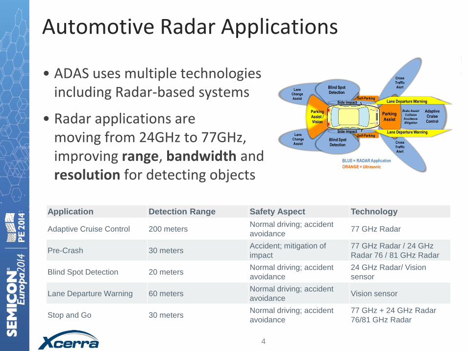
Automotive Radar Applications
Application Detection Range Safety Aspect Technology
Adaptive Cruise Control 200 meters Normal driving; accident
avoidance 77 GHz Radar
Pre-Crash 30 meters Accident; mitigation of
impact
77 GHz Radar / 24 GHz
Radar 76 / 81 GHz Radar
Blind Spot Detection 20 meters Normal driving; accident
avoidance
24 GHz Radar/ Vision
sensor
Lane Departure Warning 60 meters Normal driving; accident
avoidance Vision sensor
Stop and Go 30 meters Normal driving; accident
avoidance
77 GHz + 24 GHz Radar
76/81 GHz Radar
• ADAS uses multiple technologies including Radar-based systems
• Radar applications are moving from 24GHz to 77GHz, improving range, bandwidth and resolution for detecting objects
4

Push to Higher Bandwidth – 79GHz 5 GHz 200MHz
Source: ITU News
5

The Test Challenge for Automotive Radar
• “Sub ppm” failure rates full functional test required
• Reliable and cost-effective HVM solution
• Maximize re-use of test cell investment
• Multi-temp testing from -55 to +150°C
Source: CVEL Automotive Electronics 6

Automotive Radar Integrated Test Cell
7
• High volume production “at speed“ testing solution for ADAS Radar enabled devices
− Automotive compliant Tri-temp testing and handling
− Commercial ATE and handler platform , with optional 24GHz or 77GHz Tx and Rx
− Fully-matched contactor and interfacing assembly
• Lowest number of signal transitions provides better signal integrity
• Packaged device and WLCSP compliant
− Mechanical interfacing and integrated test cell communication
Tri-Temp Handler General Purpose ATE
Integrated 77GHz test and
contactor assembly
Optimized transmission paths

Starting point – 24GHz RF Test
• A co-development between ST and Xcerra has already implemented 24GHz functional test to maintain the highest device quality levels
• Uses flexible test cell base that can be adapted for other requirements
• Signal interfaces have been designed for optimal system-level electrical and thermal performance
• The test cell base is now being extended with new HS instrumentation and interfaces to provide a 77GHz functional test solution in collaboration with ST.
8

24GHz Test Cell Signal I/F Optimization • Complete signal path optimized between DUT and ATE through design, simulation
and measurement
– Less than 8dB of loss (23-26.5GHz)
– Less than 2dB of ripple in passband (23-26.5GHz)
– Die temp. accuracy of ±2°C (die temperature) at cold test while maintaining the stringent RF requirements
• Custom insulation on tester-side of loadboard PCB and contactor design enables shorter signal-lengths and more stable multi-temp performance
• Air flow for multi-temp support integrated with handler kit
Insulation on back of
Loadboard
Temperature Drift
Te
mp
(°C
)
-44
-40
-36
-32
-28
-24
-20
-16
0 20 40 60 80 100
time (s)
2°C
9

Elements of the 77GHz Test Cell
Contact Unit Holder
and Multi-Temp
Insulation
Tester-Handler
Docking
Loadboard and
Contactor Interface
77GHz RF Test Option
Scalable SOC
ATE System
Tri-Temp
P&P Handler
Multi-Axis TH
Manipulator
10
Optimized Tester-
Handler Communication

Key Test Technology in 77GHz Radar Test Cell
• 77GHZ Integrated contactor, adaptor & interface board
– Designed to ensure shortest possible path from 77GHz instrument to DUT
– Validated over automotive test temperature ranges
• Tri-temp (-55°C to +175°C ), Automotive-compliant Pick and Place handler and validated docking
• 77GHz Automotive Radar test option
– Configured as upgrade on scalable ATE platform to balance flexibility and cost
• Calibration of RF to device pin or ball
11
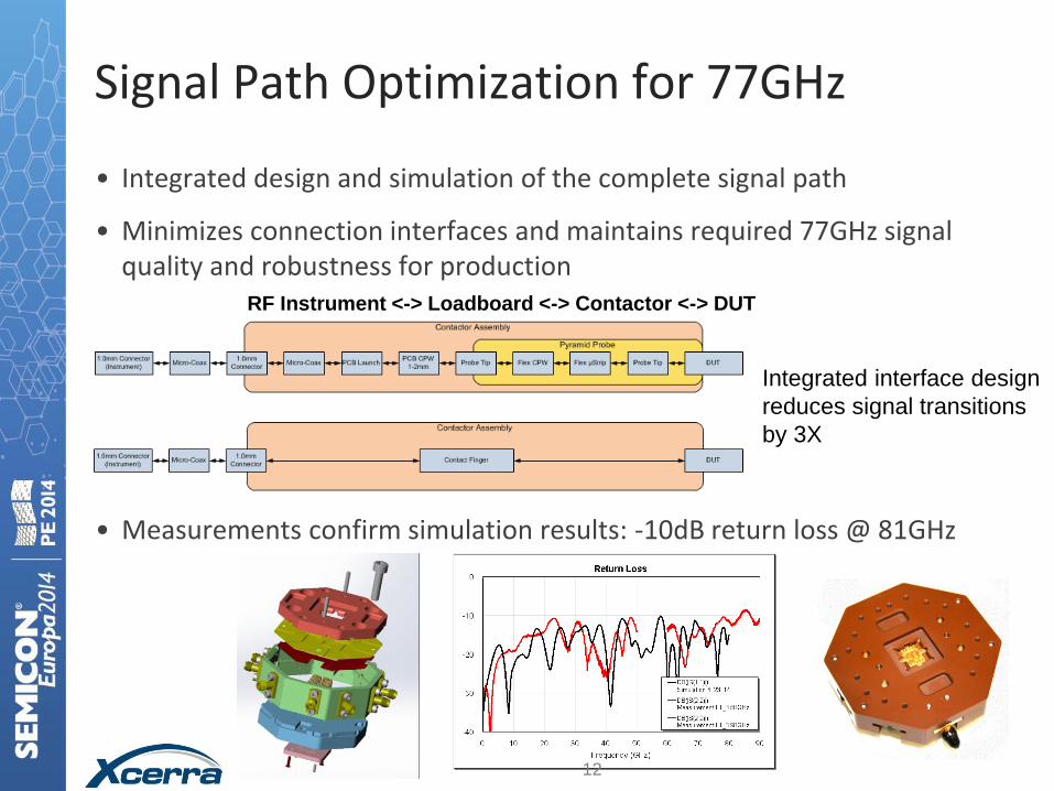
Signal Path Optimization for 77GHz
• Integrated design and simulation of the complete signal path
• Minimizes connection interfaces and maintains required 77GHz signal quality and robustness for production
• Measurements confirm simulation results: -10dB return loss @ 81GHz
RF Instrument <-> Loadboard <-> Contactor <-> DUT
Integrated interface design
reduces signal transitions
by 3X
12
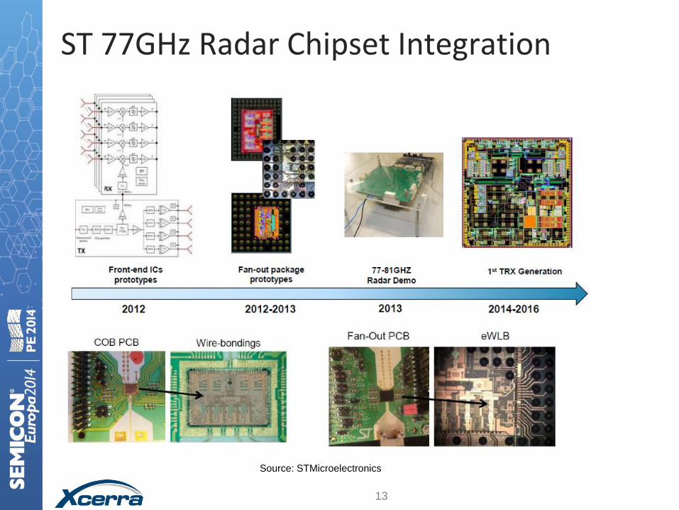
ST 77GHz Radar Chipset Integration
Source: STMicroelectronics
13
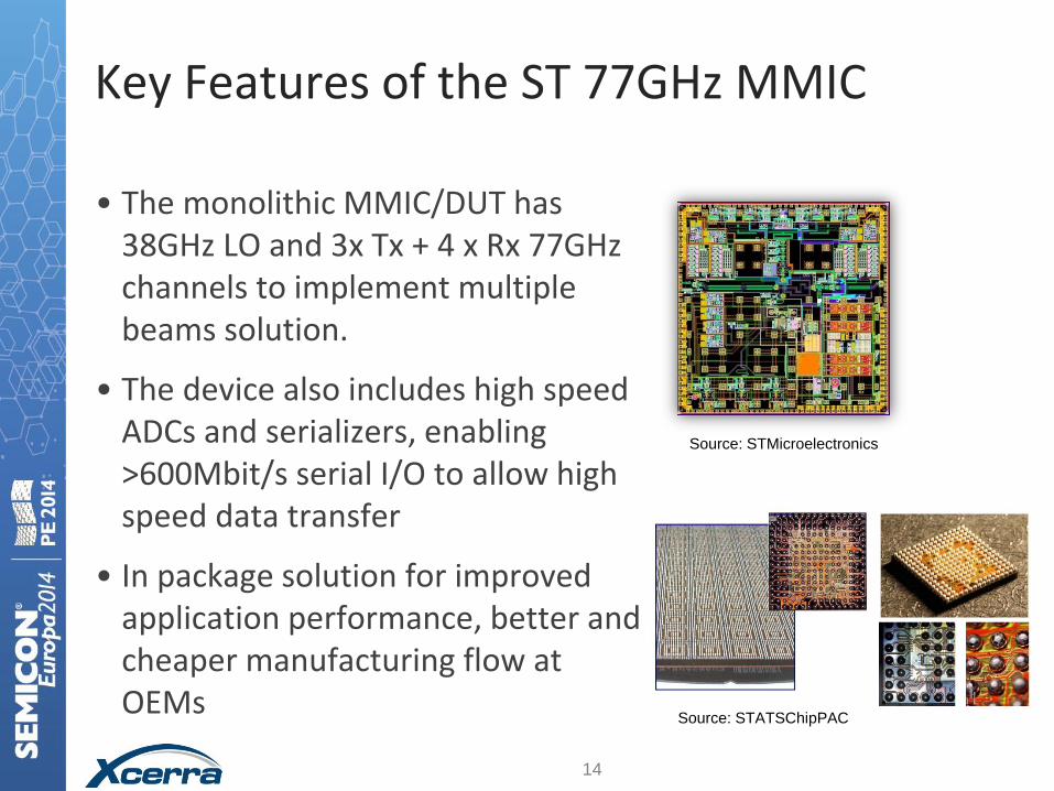
Key Features of the ST 77GHz MMIC
• The monolithic MMIC/DUT has 38GHz LO and 3x Tx + 4 x Rx 77GHz channels to implement multiple beams solution.
• The device also includes high speed ADCs and serializers, enabling >600Mbit/s serial I/O to allow high speed data transfer
• In package solution for improved application performance, better and cheaper manufacturing flow at OEMs
Source: STATSChipPAC
14
Source: STMicroelectronics

Xcerra 77G Radar Test Cell – RF test parameters for ST 77GHz MMIC
TX Output Power Levels
TX Pout vs Frequency
TX off-state power
TX Power Control
TX1 to TX2 Isolation
TX Phase Noise
Power Detectors
TX Peak Detector Sensitivity
Spurious #3 (73.5 GHz to 79.5 GHz)
Temperature Sensor (Sensitivity
and Output Voltage Range)
TX switching speed (TBC)
Amplitude Noise (TBC)
Total conversion gain
Power supply rejection
Input P1dB
Noise Figure
Channel isolation
LO input drive level
IF 3dB bandwidth
Conversion gain imbalance
from channel to channel
Phase imbalance from
channel to channel
Temperature sensor output
Tx Rx
Q-Band Measure Module(s)
Required for MOD
Q-Band Source Module(s)
Required for TX & RX
77GHz Instrument E-Band Measure
Module(s)
Required for TX
E-Band Source
Module(s)
Required for RX
Xce
rra D
UT
inte
rface
15
• Plus standard Automotive tests and high-speed digital test of ADC
• Provides highest level of test coverage for guaranteed DUT quality
Conclusions
• Test cell approach, with modular instrumentation and optimized signal interfacing, has been used in production since 2011 to provide a cost-effective solution for full-speed 24GHz testing.
• Same approach is now used for ST 77GHz automotive radar MMICs.
• Signal interface optimization and handler integration allows multi-temperature testing in production
• Result: The Automotive Radar MMICs are tested to the highest levels of coverage, to guarantee premium level quality to the Automotive OEMs.
16

Questions?