Using a Mahl-Stick as a 2-Dimensional Spatial … · entertainment, engineering, education,...
81
School of Information Technology and Mathematical Sciences Division of Information Technology, Engineering and the Environment Research Proposal for Bachelor of Computer Science (Honours) Using a Mahl-Stick as a 2-Dimensional Spatial Augmented Reality Input Device Matthew McDonald [email protected] Supervisors: Bruce H. Thomas, Ross T. Smith Date of submission: 5 / 2 / 2015
Transcript of Using a Mahl-Stick as a 2-Dimensional Spatial … · entertainment, engineering, education,...

School of Information Technology and Mathematical Sciences
Division of Information Technology, Engineering and the Environment
Research Proposal for Bachelor of Computer Science (Honours)
Using a Mahl-Stick as a 2-Dimensional Spatial
Augmented Reality Input Device
Matthew McDonald [email protected]
Supervisors: Bruce H. Thomas, Ross T. Smith
Date of submission: 5 / 2 / 2015

Copyright © 2015
Matthew McDonald
All rights reserved.

i
ABSTRACT
This dissertation presents an exploration of the effect that a mahl-stick, a traditional tool used
to support the brush hand in painting and signwriting, has in simple applications in a Spatial
Augmented Reality context. Spatial Augmented Reality uses digital projectors to add
computer generated images to real-world objects interactively and at run-time, and is used in
entertainment, engineering, education, industrial design, business collaboration and
manufacturing. Input devices to interact with these applications need to be developed and
improved. To this end pointing (selection) and steering (drawing) tasks are examined to see
how a mahl-stick can be used in a SAR application.
To evaluate this, two user studies were conducted in which participants were asked to
perform pointing and steering tasks using a stylus, with and without the aid of a mahl-stick.
Participants were measured on time, accuracy, and the number of errors made whilst
performing these tasks. Participants rated their opinions on their performance in terms of
ease, accuracy and speed of performing the tasks. Participants technique and fatigue were
also monitored.
This dissertation has focused on simple, small-scale and straight line pointing and steering
tasks on a vertical surface. Mahl-sticks have demonstrated an impaired performance for
pointing tasks, however a preference for the use of a mahl-stick for steering tasks in such
conditions was revealed. Fatigue was found to have an influence on task performance and
user preferences and it took little time before it affected users in a negative fashion. An
artefact of this research is a new AR input device.

ii
DECLARATION
I declare that:
this thesis presents work carried out by myself and does not incorporate without
acknowledgment any material previously submitted for a degree or diploma in any
university;
to the best of my knowledge it does not contain any materials previously published or
written by another person except where due reference is made in the text; and all
substantive contributions by others to the work presented, including jointly authored
publications, is clearly acknowledged.
Matthew McDonald
5th
February 2015

iii
ACKNOWLEDGMENTS
I would like to thank my supervisors, Bruce Thomas and Ross Smith, for their advice,
opinions and support over the past year. Thanks to everybody in the Wearable Computer Lab:
Michael Marner, James Baumeister, James Walsh, Andrew Irlitti, Neven Elsayad, and Tim
Simon - you're all awesome. I would also like to thank my employers and colleagues for
providing me the time I have needed to complete my studies. Finally, I would like to thank
my family and friends for their support and good humour.

iv
TABLE OF CONTENTS
1. INTRODUCTION................................................................................................................ 1
1.1. The Problem .................................................................................................................... 2
1.2. Research Question ........................................................................................................... 2
1.3. Contributions ................................................................................................................... 3
1.4. Dissertation Structure ...................................................................................................... 3
2. BACKGROUND .................................................................................................................. 5
2.1. Augmented Reality .......................................................................................................... 6
2.2. Spatial Augmented Reality .............................................................................................. 8
2.3. Tracking ........................................................................................................................ 13
2.4. Spatial Augmented Reality User Interfaces and Input .................................................. 16
2.5. Fitts' Law ....................................................................................................................... 20
2.6. Steering Law ................................................................................................................. 23
2.7. Mahl-Sticks ................................................................................................................... 26
2.8. Summary ....................................................................................................................... 28
3. RESEARCH METHOD .................................................................................................... 29
3.1. Pointing Task Study Methodology ................................................................................ 30
3.1.1. Goal ........................................................................................................................ 30
3.1.2. Hypothesis .............................................................................................................. 31
3.1.3. Pointing Task Study Design ................................................................................... 31
3.2. Steering Task Study Methodology ................................................................................ 36
3.2.1. Goal ........................................................................................................................ 36
3.2.2. Hypothesis .............................................................................................................. 36
3.2.3. Steering Task Study Design ................................................................................... 37
3.3. User Study Environment ............................................................................................... 40
3.3.1. Projection System ................................................................................................... 40
3.3.2. Tracking System ..................................................................................................... 43
3.3.3. Stylus ...................................................................................................................... 45
3.3.4. Mahl-Stick .............................................................................................................. 46

v
4. ANALYSIS ......................................................................................................................... 47
4.1. Pointing Task User Study .............................................................................................. 49
4.2. Steering Task User Study .............................................................................................. 52
4.3. Qualitative Results ........................................................................................................ 55
4.3.1. Observations of Participants ................................................................................... 55
4.3.2. Questionnaire Results ............................................................................................. 57
4.4. Summary of Results ...................................................................................................... 59
5. CONCLUSION .................................................................................................................. 60
5.1. Pointing Tasks ............................................................................................................... 60
5.2. Steering Tasks ............................................................................................................... 61
5.3. Future Directions & Final Comments ........................................................................... 61
REFERENCES ....................................................................................................................... 63

vi
LIST OF ABBREVIATIONS
2D 2-Dimensional
3D 3-Dimensional
AR Augmented Reality
CAVE Computer Automated Virtual Environment
CRT Cathode Ray Tube
HMD Head-Mounted Display
GUI Graphical User Interface
IR Infra-Red
LED Light Emitting Diode
RFID Radio-Frequency Identification
SAR Spatial Augmented Reality
SID Spatially Immersive Display
TUI Tangible User Interface
VR Virtual Reality

vii
LIST OF FIGURES
Page Figure
6 1.1 The Mixed Reality Continuum
26 2.1 A Mahl-stick in Use
32 3.1 Arrangement and Size of the Projected Targets in the Pointing Task Study
32 3.2 The Preferred Height of the Targets in Relation to a Participants' Height
33 3.3 Performing the Pointing Task With and Without the Mahl-Stick
34 3.4 Example Pointing Task
37 3.5 Arrangement and Size of the Projected Targets in the Steering Task Study
38 3.6 Example Steering Task
39 3.7 Performing the Steering Task With and Without the Mahl-Stick
40 3.8 Occlusion from a Single Projector
41 3.9 Description of Virtual Rear Projection
42 3.10 Showing Virtual Rear Projection in Action
44 3.11 The Placement of Motion Capture Cameras Around the Scene
44 3.12 The Combined Coordinate System for the Cameras and Projectors
45 3.13 The Stylus used in the User Studies
46 3.14 The Mahl-Stick used in the User Studies

viii
LIST OF FORMULAE
Page Formula
20 1 Fitts' Law
20 2 Fitts' Law as derived originally by Fitts (1954)
20 3 Welford Formulation of Fitts' Law
20 4 Shannon Formulation of Fitts' Law
21 5 MacKenzie & Buxton's First Formulation of Fitts' Law (1992)
21 6 MacKenzie & Buxton's Second Formulation of Fitts' Law (1992)
21 7 Kopper et al.'s Formulation of Fitts' Law (2010)
21 8 Appert et al.'s Formulation of Fitts' Law (2008)
21 9 Yang and Xu's Formulation of Fitts' Law (2010)
22 10 Zhang et al.'s Formulation of Fitts' Law (2012)
23 11 Steering Law as derived originally by Accot & Zhai (2001)
23 12 Accot & Zhai's Formulation of Steering Law (2003)
23 13 Grossman & Balakrishnan's Formulation of Steering Law (2005)
23 14 Pastel's Steering Law for steering around corners (2006)
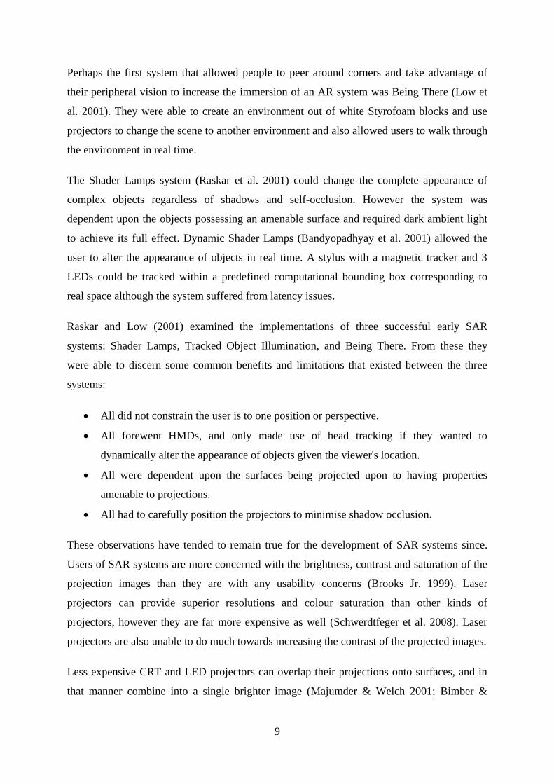
24 15 Zhou & Ren's Formulation of Steering Law (2010)
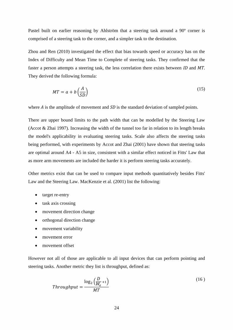
24 16 MacKenzie et al.'s Throughput Metric (2001)

1
1. INTRODUCTION
Augmented Reality (AR) is the integration of computer-generated sensory information
directly into the real world that occurs in real-time, is interactive and aligns real and virtual
objects (Azuma 1997). This differs from Virtual Reality (VR) in that AR uses the real
environment whereas VR creates an entirely virtual environment (Milgram & Kishino 1994).
Spatial Augmented Reality (SAR) is a form of AR in which computer-generated imagery is
projected directly onto objects in the real world, most often achieved through the use of
projectors, flat panel displays and smart boards (Raskar et al. 1998). SAR has applications in
a large range of fields including entertainment, education, industrial design, business
collaboration, ordinary workflow improvements, and manufacturing.
Interactions with a SAR system can be achieved by various means but is better achieved with
physical tools, props and by registering the user's body movements (Mine et al. 1997, Marner
et al. 2011). With many different applications, there are a wide variety of tools and methods
to interact with these systems. One such simple tool currently used is the stylus. The stylus
can be used as a pen and to provide more precision when performing selection tasks. These
two actions can be described as steering tasks (dragging the stylus along a specific path
across the surface of an object) and pointing tasks (clicking on a specific point on the surface
of an object) respectively.
One common steering task is drawing a line. Drawing lines is an integral part of the creative
process as it is part of seeing and understanding the subject matter itself. Combining lines is
an effective way to describe and share what is contained within a person's imagination, and
these combinations often take the forms of pictures and text. A straight line can be defined as
a path between 2 endpoints. This thesis is an examination in the enhancement of free-hand
drawing through the use of a mahl-stick, a supporting rod usually 1 meter in length for the
brush hand used traditionally in painting and signwriting, within the context of Spatial
Augmented Reality.

2
1.1. The Problem
One problem that can emerge in undertaking pointing and steering tasks lies in the accuracy
obtained when performing them. It can be difficult to steer lines along a precise path by hand
or to select a specific point on the surface on an object. The software in drawing systems can
interpolate between a drawn line and what the user intended to draw by simplifying, adjusting
and moving the drawn line to be neater. However it is impossible to know with certainty
which features of a drawn path are desired and which features are not. Alternatively a
person's skill in drawing can improve to the point where they will draw lines exactly how
they want; however obtaining this level of skill can take years of practice.
A mahl-stick reduces the difficulty in drawing accurate lines by providing support for the
hand performing the drawing task, and by decreasing the amount of movement the arm needs
to make to draw a line. A mahl-stick is held by the non-drawing hand roughly horizontal,
with the far end resting upon a stable surface. This provides a stable platform for the brush
hand to rest upon. Normally when drawing the shoulder, elbow, wrist and fingers all need to
move. If the drawing hand rests on a mahl-stick only the wrist and fingers need to move,
decreasing the number of body parts that need to move and focusing attention toward the
most precise: the fingers. My knowledge of mahl-sticks was obtained from my training in
Signwriting at the Gilles Plains TAFE, South Australia.
1.2. Research Question
The focus of this research is to evaluate the effect that a mahl-stick has when performing
simple pointing and steering tasks in Spatial Augmented Reality applications when using a
stylus.
There are two sub-questions in relation to this research question:
How do novice and experienced users compare with the use of a mahl-stick in
performing pointing and steering tasks.
What learning effect is observable in using a mahl-stick.
An artefact of this research is a new handheld SAR drawing device.

3
1.3. Contributions
There has been a trend in research to improve the accuracy in pointing and steering tasks
algorithmically or with more complex and sophisticated tracking and input devices. This
research is focused on a proven, simple, centuries-old technique to improve accuracy by
providing physical support to the user's drawing hand instead by way of a mahl-stick.
The sub-questions of the research also address the learning effect of pointing and steering
tasks. The learning effect is usually excluded from results in the analysis following studies or
pointed out as a mitigating variable in the results; with this research I aimed to specifically
look into the effect learning has in completing tasks.
Furthermore this research provides an analysis of mahl-sticks in completing pointing and
steering tasks. To the best of my knowledge this is something that has never been
investigated before. The method chosen to achieve this is with analysis of captured time and
movement data, user opinions, and observation of participants in a user study, with the
difficulty of the tasks tested against Fitts' Law and the Accot-Zhai Steering Law.
Lastly, an artefact of this research is a new input device for SAR applications.
1.4. Dissertation Structure
This thesis is structured as follows. In Chapter 2 the body of knowledge upon which this
research is built is explored. A definition of Augmented Reality (AR) is given and categories
of AR systems are described. Following that a definition of Spatial Augmented Reality
(SAR) is provided, several successful SAR implementations are described, and methods and
pitfalls in their development are explained. Various methods for tracking and virtual-real
object alignment in AR systems are listed next, followed by a description of various SAR
user interfaces and input devices. Fitts' Law and the Accot-Zhai Steering Law, two formulae
used to compare input devices on their capacity to perform pointing and steering tasks, are
detailed. Lastly mahl-sticks are described, and Chapter 2 is concluded with a summary.
To answer the research questions, two concurrent user studies were conducted. The
methodology for both user studies is described in Chapter 3. First described is a pointing task
study was conducted to test the performance of pointing tasks with and without the aid of a
4
mahl-stick. This is followed by the methodology for a steering task study, again conducted to
compare performance with and without the stick. Both user studies were ran simultaneously,
using the same equipment and environment. The chapter is concluded with detail describing
the projector system and its' calibration, the tracking system in use, and the construction and
use of the stylus and mahl-stick used in the studies.
In Chapter 4 the analyses of the results from both user studies is described. Both quantitative
and qualitative data were recorded during the user studies. The qualitative data for the
pointing task study is analysed first followed by that of the steering task study. The
quantitative data captured during the study was obtained by observation of the participants,
and by a questionnaire following the conclusion of the studies. The observation data is
analysed before the results of the questionnaire. Chapter 4 is concluded with a summary of
the results.
The thesis is concluded in Chapter 5. The body of knowledge provided in Chapter 2 is
summarised in brief. The methodology and analysis of results of the pointing task study are
described, followed by that of the steering task study. The chapter is concluded with future
directions for research of mahl-sticks in SAR systems, and final comments regarding this
dissertation.

5
2. BACKGROUND
This section of the thesis serves to define the context of the research described in this
dissertation by providing a review of relevant literature. Firstly Augmented Reality and
Spatial Augmented Reality are defined, and various implementations of these systems is
provided. To this end, various pitfalls and calibration techniques are described. This is
followed by a description of various tracking techniques. Whilst tracking within SAR
systems was not a focus in this research, it is a fundamental aspect of interactive SAR
systems such as those in which a stylus is used. This is followed by an exploration of various
user interfaces and input devices in SAR systems.
Fitts' Law and the Steering Law are then reviewed to provide quantitative measurements for
comparing the difficulty of user input systems. These are mathematical formulae that are
standard in comparing non-keyboard input devices but possess a wide variety of formulations
and limitations. As such these were examined as they were used to help analyse the results
obtained in this research.
This is followed with a description of mahl-sticks in greater detail to explain the manner in
which they are used. This chapter is concluded with a summary of the information described
in the above.

6
2.1. Augmented Reality
In 1965 Ivan Sutherland wrote in The Ultimate Display of a computer device that is able to
control the existence of all matter in a room, creating virtual objects indistinguishable from
real world objects. Of this he wrote:
The ultimate display would, of course, be a room within which the computer can
control the existence of matter. A chair displayed in such a room would be good
enough to sit in. Handcuffs displayed in such a room would be confining, and a bullet
displayed in such a room would be fatal.
This described all physical reality being altered and controlled by digital information.
However he also described a system in which the real sensory information of objects is
altered digitally. This integration of computer-generated sensory information directly into the
real world in real-time is known as Augmented Reality (AR) (Azuma 1997). Azuma et al. in
2001 provided a definition of AR that it:
combines real and virtual objects in a real environment;
runs interactively, and in real time; and
registers (aligns) real and virtual objects with each other.
The Mixed Reality Continuum (Figure 1.1) described by Milgram and Kishino (1994) defines
AR in relation to the real environment and Virtual Reality (VR). At one end lies the real
environment, and at the other end lies Virtual Reality which is entirely computer generated.
The line between them represents the gradual inclusion of computer generated information
and the resulting exclusion of the real environment. AR is placed towards the real
environment, indicating that the focus is on adding digital information to the real world.
Figure 1.1: The Mixed Reality Continuum (Milgram & Kishino 1994)
These augmentations can be for any sense: sight, hearing, taste, smell, etc., though the most
prevalent augmentations are sight-based. AR visualisation can be achieved with head-

7
mounted displays (HMDs), projectors, or specialised display surfaces such as tablets and
screens.
HMDs come in two flavours: Optical See-Through where augmentations are projected onto
glasses or directly on the retina of the eye by lasers, and Video See-Through where
augmentations are added to video displays. HMDs can also be monoscopic where both eyes
receive the same image, or stereoscopic where each eye receives an adjusted image to allow
for the illusion of depth. The first AR system was created by Sutherland in 1968 and named
'The Sword of Damocles', and it also featured the first HMD (Sutherland 1968). The HMD
was stereoscopic optical see-through and suspended from the ceiling, tracking and updating
wireframe objects as the user moved.
Whilst it is easy to add light and translucent objects to an optical see-through scene, adding
shadows and solid objects to the environment can be much more challenging. Bimber and
Fröhlich (2002) developed a technique where the light source in the environment is replaced
by projectors. Objects can be made to appear solid by not projecting light where the virtual
object would go for the viewer's perspective. Shadows can also be created by projecting only
some light onto the environment where the shadow would be.
Completely virtual objects displayed through HMDs provide no haptic feedback to users. The
X'tal Vision system (Inami et al. 2000) uses a plane of retro-reflective glass as an optical see-
through HMD and a head-mounted projector to help create viewer-perspective augmented
objects that can be touched and interacted with in real time, using front projection techniques.

8
2.2. Spatial Augmented Reality
Using projectors, flat panel displays and smart boards to project directly onto real objects in
the real world is known as 'Spatial Augmented Reality' (SAR) (Raskar et al. 1998). The key
advantage of SAR systems is that the user need not encumber themselves with potentially
expensive or heavy HMDs because the augmentations are provided directly into the
environment itself. As such much of the research and development of AR systems has moved
towards SAR (Lantz 1996). SAR currently has a wide variety of applications across many
fields such as in education (Bimber & Raskar 2005), entertainment (Oda & Feiner 2009),
business collaboration and workflow (Wellner 1993), industrial design (Marner et al. 2011),
and review (Verlinden et al. 2009).
The seminal work on the CAVE (Computer Automated Virtual Environment; Cruz-Neira et
al. 1993) made use of projection technology on the surface of the walls of a room to act as
shared workspaces in a collaborative workplace environment. The users of the system wore
tracked HMDs that provided further augmentations tailored to each individual's requirements.
User studies of this system revealed an interesting behaviour in regards to how people dealt
with occlusion: people quickly resolved occlusions by removing the offending object or body
part from view. Occlusions caused by other people or objects outside of their ability to move
were better controlled by a single user controlling the proceedings such that occlusions were
unlikely to occur.
Concurrently developed, the DigitalDesk was a system that aimed to combine the physical
work desk with a virtual one to improve workflow (Wellner 1993). The CAVE and
DigitalDesk systems led to further research on using AR to improve collaboration and
business workflow and by 1996 a panel at SIGGRAPH '96 organised by Ed Lantz had
already noted a trend away from HMDs towards SAR, then termed Spatially Immersive
Displays (SID). The Office of the Future (Raskar et al. 1998) described a vision for future
workspaces where every surface is a possible interactive surface. The research also
introduced imperceptible light patterns to calibrate camera-projector pairs and used blending
techniques to combine the overlapping imagery from different projectors.
Another early SAR system was the Luminous Room (Underkoffler et al. 1999) which made
use of every surface of a room as a projector display surface and any object within that room
could be given a passive role to perform virtual actions.
9
Perhaps the first system that allowed people to peer around corners and take advantage of
their peripheral vision to increase the immersion of an AR system was Being There (Low et
al. 2001). They were able to create an environment out of white Styrofoam blocks and use
projectors to change the scene to another environment and also allowed users to walk through
the environment in real time.
The Shader Lamps system (Raskar et al. 2001) could change the complete appearance of
complex objects regardless of shadows and self-occlusion. However the system was
dependent upon the objects possessing an amenable surface and required dark ambient light
to achieve its full effect. Dynamic Shader Lamps (Bandyopadhyay et al. 2001) allowed the
user to alter the appearance of objects in real time. A stylus with a magnetic tracker and 3
LEDs could be tracked within a predefined computational bounding box corresponding to
real space although the system suffered from latency issues.
Raskar and Low (2001) examined the implementations of three successful early SAR
systems: Shader Lamps, Tracked Object Illumination, and Being There. From these they
were able to discern some common benefits and limitations that existed between the three
systems:
All did not constrain the user is to one position or perspective.
All forewent HMDs, and only made use of head tracking if they wanted to
dynamically alter the appearance of objects given the viewer's location.
All were dependent upon the surfaces being projected upon to having properties
amenable to projections.
All had to carefully position the projectors to minimise shadow occlusion.
These observations have tended to remain true for the development of SAR systems since.
Users of SAR systems are more concerned with the brightness, contrast and saturation of the
projection images than they are with any usability concerns (Brooks Jr. 1999). Laser
projectors can provide superior resolutions and colour saturation than other kinds of
projectors, however they are far more expensive as well (Schwerdtfeger et al. 2008). Laser
projectors are also unable to do much towards increasing the contrast of the projected images.
Less expensive CRT and LED projectors can overlap their projections onto surfaces, and in
that manner combine into a single brighter image (Majumder & Welch 2001; Bimber &

10
Emmerling 2006). A side effect of combining projections is the final image can have a higher
focus, improving the image quality. Projections from multiple projectors had been combined
since at least the Office of the Future (Raskar et al. 1998), however this was done in order to
create larger images rather than brighter ones. The technique described by Raskar et al.
(1999) used projected bands from each projector being decoded individually to discover the
overlaps. The projections were then alpha blended and stitched together to try and create
seamless images.
Shadow occlusion can be reduced or even eliminated by using several redundant projections
focused upon the same plane. If part of the image from one projector is occluded, another
projector can still project onto where the image was (Summet et al. 2005). The occluding
object can be detected and be not projected onto in real time.
Aligning projections with real world objects has proven a difficult task. Early systems
required a time-consuming manual calibration. The Office of the Future (Raskar et al. 1998)
introduced imperceptible light patterns to calibrate camera-projector pairs, making the
process slightly easier and faster. Zhang (2000) developed a technique to calibrate a
projector-camera pair by calculating the intrinsic and extrinsic parameters of either the
camera or the display surface and then moving either one or the other a minimum of 2 times.
A self-correcting projector-camera pair technique was developed by Raskar & Beardsley
(2001) which was able to perspectively-correct keystone the projection to the planar target
surface.
The iLamps system (Raskar et al. 2003) improved calibration and registration on multiple
projectors by using colour banding and did not require projectors and cameras to be aligned
on the same axis. Light sensors embedded into the object being projected upon can
automatically calibrate the projections with the surface without the use of a camera (Lee et al.
2004).
Another challenge found with SAR is that projecting the desired appearance straight onto an
arbitrary object often gives unsatisfactory results as the original colouration of objects with
non-Lambertian surfaces is visible through the projection. Grossberg et al. (2004) developed
a technique for capturing the colour channels of the object and then applying a compensation
filter onto the projection image that resulted in the objects own appearance being washed out
with the application of new light. Structured light patterns have been used to perform

11
radiometric compensation in projector-camera systems to help improve the colour quality
(Zollman & Bimber 2007). Such light structures can be cycled faster than the human eye can
perceive.
It has proven difficult to provide view-dependent projections for different users in multi-user
SAR systems. The regular use of projections provides for the same image to been seen by all
viewers from all angles. The Being There system (Low et al. 2001) which allowed viewers to
walk through the SAR environment provided HMDs to create the appearance of perspectively
correct windows through solid objects. Another method was developed by Agrawala et al.
(1997) in which shutter glasses provided low bandwidth images to each eye for up to two
people.
Images have also been projected onto inverted mirrored cones whilst the viewers wear HMDs
tracking their view orientation, allowing the users to see perspectively correct computer
generated imagery in a single location (Bimber et al. 2003). This has been used to allow
people to view fossil specimens, and see the organisms’ various tissues layered upon it
(Bimber et al. 2002). A similar idea has been to project directly onto artwork in galleries,
allowing viewers to see one at a time the various drafts and original forms of the paintings as
the artist worked on them before settling on the final appearance (Bimber et al. 2005).
Getting projections on all sides of all desired objects can be a challenge. Whilst placing more
projectors throughout the environment is an option, it can be expensive and infeasible with
certain environments and applications. In 2001 Pinhanez developed a technique in which a
movable mirror is used to project onto surfaces outside the line of sight of a projector,
without having to recalibrate the system. Having users hold the projectors is another method
to augment real world objects in their physical location (Beardsley et al. 2005), and such
projectors can also be used as an input device.
SAR can greatly decrease the cost and time taken to prototype in industrial design. Projected
light is faster and cheaper to change than clay modelling and 3D printing, and ideas can be
trialled ad hoc efficiently without having to alter the actual surface of the object and the
environment that contains it. Being able to cycle through different appearances and
configurations also reduces the number of physical objects needing to be created and reduces
storage space required for prototypes (Marner et al. 2011).

12
Improving the quality of SAR systems has been shown to improve the sense of object-
presence which can improve the experience that people have interacting with the system
(Stevens et al. 2002). This improvement has been demonstrated to help improve the learning
and performance of tasks (Witmer & Singer 1998). However the sense of touch can reduce
object-presence when the viewer becomes aware that the augmentations do not possess the
haptic properties the visual augmentations suggest (Bennett & Stevens 2005).

13
2.3. Tracking
Most interactive SAR systems need to track the position and orientation of objects in order
for the real and virtual objects to properly align (Marner 2013). If props and simple tools are
being used to interact with the SAR system, these need to be tracked too. Similarly, tracking
users can allow for view-dependent projections. This section provides a brief overview of
tracking techniques in SAR systems.
There are six main methods to track objects in the real world: magnetic, acoustic, inertial,
mechanical, optical, and radio / microwave sensing (Bhatnagar 1993, Welch & Foxlin 2002).
Magnetic trackers measure a local magnetic field vector using magnetometers or
electromagnetic coils. These trackers are usually lightweight, avoid line-of-sight
issues and possess high update rates, however they are all vulnerable to distortion
from environmental magnetic, electromagnetic, and metallic or ferromagnetic fields.
Acoustic trackers measure the time it takes ultrasonic pulses to reach receivers to
track objects over time. These trackers are lightweight but are limited by the low
speed of sound, suffer from echoes, require line-of-sight and are subject to disruptions
in air temperature and humidity.
Mechanical trackers measure the position and orientation of objects attached to the
end of a movable mechanical arm. These trackers are simple to construct (the Sword
of Damocles system built by Sutherland in 1968 used mechanical tracking) but the
limitation that objects be in range of the arm is so severe that they are largely obsolete
in modern SAR systems.
Inertial trackers make use of gyroscopes and accelerometers to capture the movement
in 3 linear axes. From these a transformation matrix is calculated to determine the
position of the object in the real world. These trackers are self-contained, have high
update rates and face no interference from electronic fields and ambient noise.
However inertial trackers suffer from jitter and drift, in which even a small bias error
in one axis will cause the estimates to drift vast distances in only a short time.
Optical trackers track visual cues on objects or in the environment. They possess high
update rates, large working volumes and are unaffected by the presence of metals and
electromagnetic fields in the environment, however they also suffer from line-of-sight
issues and can be affected by ambient light and infrared radiation.

14
Radio and microwave tracking embeds small tags that emit radio or microwave
electromagnetic waves which can then be tracked. This offers a greater range than
magnetic trackers and are largely unaffected by wind and air temperature, however
the waves are rapidly attenuated in water: essentially this makes the human body
opaque for this tracking technique.
All tracking techniques share a problem in that latency exists between the time a person
makes an input and when the system registers it. Alleviating this by predicting future
movement is possible only to a limited extent as humans are unpredictable. For this reason a
tracking technique which has a high update rate is usually desired. Optical tracking is the
most common method used today in part because of its high update rate but also because they
are relatively simple to implement and SAR systems already tend to involve cameras.
Fiducial markers, simple unique high-contrast patterns, are a popular optical tracking
technique. Many AR systems detect fiducials in the environment and display projections
relative to their positions, and users are intuitively able to manipulate them to perform tasks
(Kato & Billinghurst, 1999). Software libraries such as ARToolKit are able to detect fiducials
in the environment to determine position, and the ARToolKitPlus is an updated version able
to run on mobile devices (Wagner 2007).
It has been has been demonstrated that placing fiducial markers within the environment and
the camera / tracker placed on the object is more accurate than the reverse as the distances
between the markers is greater allowing for greater precision (Bhatnagar 1993). However for
most SAR systems this is impractical.
Another form of fiducial marker is Random Dot Markers, unique patterns of dots that can
easily be rotated and arranged into any shape (Uchiyama & Saito 2011). One advantage these
markers have over other types is that they don’t require hard edges, and they still work even
when partially occluded or incomplete. They can also be deformed, and the deformation can
be detected and measured (Uchiyama & Marchand 2011).
The Bokeh effect has also been used to decrease the size of fiducial markers detected by
ordinary cameras down to 3mm from a distance of up to 4m away by taking advantage of the
effect that occurs when out of focus scene point is focused into a blur on the camera sensor
(Mohan et al. 2009).

15
Fiducial markers themselves are obtrusive, often don't work if partly occluded, and require
high ambient light to be effective whilst SAR systems perform best in low light conditions
(Marner et al. 2011). As such invisible or active (reacting to the immediate environment)
markers are usually preferred in SAR systems.
There are several different techniques used to create invisible fiducials. Grundhöfer et al.
(2007) used the green channel, to which the human eye is most sensitive, to encode fiducials
into a projected image one frame, and its inverse the next. As this process repeats, the human
eye is unable to detect the fiducials whereas a computer can. However this technique assumes
the presence of the green channel throughout the entire image to place the fiducial in the first
place. Using other channels can result in a more noticeable decrease in brightness.
Infrared (IR) fiducials are another way to create invisible fiducials though care needs to be
taken so that other sources of infrared light, such as the sun or fluorescent lighting, do not
reduce their clarity (Nakazato et al. 2005). Infrared can be observed by itself or with visible
colours as well. Park & Park (2004) used a colour camera and an IR camera focused on
precisely the same location through the use of a half-silvered mirror to detect infrared
fiducials whilst obtaining the visible spectrum image as well. Infrared fiducials have been
placed on the ceilings of interiors to navigate users through interior spaces (Nakazato et al.
2008).
Colour blobbing is another optical tracking technique in SAR systems which allows for the
tracking of objects of any colour in real time (Rasmussen et al. 1996). Colour blobbing is a
simple image processing technique in which the centre of unique blobs of colour is
discovered. Multiple objects can be tracked over time by performing this across frames.
Embedding optical and radio tags into objects is another tracking technique gaining
popularity in AR applications. In the Prakash system (Raskar et al. 2007) IR tags emit coded
signals that photosensors are able to detect and from there calculate the motion, orientation
and illumination of the tagged points. They used this system to embed virtual objects into a
live capture of a scene. RFID tags have been embedded into objects for self-description; once
detected the system sends a grey code to the RFID which decrypts it and sends it back. From
this the system is able to determine the location of an object and project onto it (Raskar et al.
2004).

16
2.4. Spatial Augmented Reality User Interfaces and Input
As previously stated, SAR has many applications in a wide range of fields including
education, entertainment, business collaboration and industrial design. As AR augments
objects in the real world, there is no one size fits all approach for interacting with these
systems and the right tool has to be selected for the task at hand (Brooks Jr. 1999).
Interactions within SAR systems is better done with physical tools and manipulating props, or
by capturing the movement of the user's own body (Marner 2013). This section describes
interfaces and input methods to interact with SAR systems.
The cognitive load of using a tool or system is increased with the number of different
functions given to it. Likewise the cognitive load of a system is increased the more the
system is capable of performing (Marner & Thomas 2010). Using an all purpose tool is more
difficult for users than using their own hands and body movement to interact with a fully
virtualised system (Mine et al. 1997). Similarly it is easier for people to interact with a virtual
object when they possess a physical representation or model of that object in their hands, with
users preferring simple props to complex ones. For example, in a prop used to navigate a 3D
image of a human brain, neurosurgeons preferred to use a simple ball rather than dolls head
(Hinckley et al. 1994).
2-Dimensional GUIs can be augmented into the real world in a multitude of ways (Feiner et
al. 1993). GUIs are already understood by users due to their prevalence in desktop and
mobile computing and there exist numerous variations on GUI interactions (Bier et al. 1993).
However the traditional techniques used for navigating 2D spaces, such as panning and
tilting, are often disorientating for users in AR applications. Physical navigation (people
moving their eyes, hands, body, the object, the environment, etc.) is preferred by users if their
movement is not restricted by corded or immobile input devices (Ball, North & Bowman
2007).
Many GUI manipulation tasks are pointing or steering tasks in nature: 'clicking' on objects or
moving along certain paths. Both pointing and steering tasks can be virtualised through
another surface or device, performed directly, or performed with a distal device such as a
laser pen. There are other methods to interact with GUIs in AR that do not necessary include
point and steering. In the Tinmith System (Piekarski & Thomas 2002), the user wore
electronic gloves in which finger and hand movements could manipulate GUI components.

17
SixthSense (Mistry & Maes 2009), a neck-worn pendant projector-camera system, captures
hand gestures and interactions made in front of the user. Shadow Reaching (Shoemaker et al.
2007) is a form of distal pointing which makes use of the user's shadow to interact with
distant virtual objects.
Motion Swarms (Nguyen et al. 2006) is a system in which an audience acts as input by
creating a virtual swarm of particles controlled by movement in the audience. They used this
in applications in which an audience controlled a virtual beach ball, played music, and
painted a picture.
Cao & Balakrishnan (2003) devised a system in which the movement of a handheld projector
affords certain kinds of input, whilst a pen provided for alternative forms of input.
Laser pointers are another type of input device used in AR applications. An early study of
laser pointers revealed they are slower than using a traditional keyboard and mouse, and
suffer from jitter (Olsen Jr. & Nielsen 2001). One way to decrease jitter and improve
accuracy is to change the way in which a user holds the pointer. An 'arrow-holding' technique
in which the user positions the laser pointer out in front of their eyes such that they look
down the length of the pointer at the target has been demonstrated to offer the overall best
results for accuracy across large surfaces at the cost of the user's arm fatigue (Jota et al.
2010). Another method to decrease jitter and improve accuracy is to create a virtual bubble
around the point in which that if the point remains within it, the position within the bubble is
stable (Forlines et al. 2005).
Tracking laser pointers in the real world can be difficult due to jitter over increasingly large
distances, camera latency, and mis-registration issues. Kurz et al. (2007) created a reliable
method to track a laser pointer that started by creating a normal map of the environment. The
laser pointer could then be identified by comparing variance in the colour levels of ensuing
frames.
In a comparison of input devices for controlling a cursor on 2D surfaces, laser pointers were
found to perform worse than using a SmartBoard, a mouse, and relative mapping (Myers et
al. 2002). Relative mapping is a technique in which interactions on a larger surface are made
on a smaller device, such as a tablet, and are mapped to the larger surface in real time. This
allows a user to remain in place whilst interacting with a far larger display without having to
use distal pointing input. This makes relative mapping faster than interacting with the larger

18
surface directly in unimanual tasks, but not in bimanual ones (Forlines et al. 2007). Problems
with relative mapping are the slower deceleration experienced in virtual pointing, and a
reluctance of users to take advantage of virtually assisted targeting (Graham & MacKenzie
1996). Ninja Cursors (Kobayashi & Igarashi 2008) offers a partial solution to some of these
problems by placing several cursors on the environment which move in unison, decreasing
the distance a single cursor has to cover.
AR allows computer applications to more closely work with people to improve their work
processes. For example, the HandSCAPE (Lee et al. 2000) turns a measuring tape into an
input device to improve box packing into delivery vehicles. Users measure the three
dimensions of a box (length, width and height) and the system automatically stores these.
Once all boxes are measured, it arranges them in size and in order to be delivered in the most
optimal arrangement to fit in the vehicle. The ordering of the boxes is then projected to the
shipping workers.
Schwerdtfeger and Klinker (2008) compared several different methods of highlighting the
location of certain stored objects using a HMD to improve order picking tasks. The methods
examined were framing the target, drawing an arrow to the target, and creating a tunnel to the
target. These were demonstrated to improve the time taken to complete order picking tasks,
with framing and subtle tunnelling proving the most effective.
A Tangible User Interface (TUI) is one in which real-world objects are used to control a
variety of functions. Whilst the computer mouse is a common TUI device, TUIs can take
many forms. For example, simple blocks and cubes have been used as a TUI (FitzMaurice et
al. 1995). The IncreTable (Leitner et al. 2008) combines TUIs with projected images to create
a mixed reality game that operates in real time. The virtual objects are controlled with an
Anoto pen, and real objects are tracked with a camera. The system allows people to take a
virtual car, steer it up the incline of a real book, and perform a jump over the other side.
LEGO OASIS (Ziola et al. 2010) is a projector-camera system in which individual Lego
blocks are treated as projection surfaces mirrored by virtual objects. As Lego blocks are
combined, the nature and properties of the virtual block objects are also changed.
The Tango (Kry & Pai 2008) is a TUI with an accelerometer and 256 pressure sensors where
hand pressure is used as input for 3D interaction. A system using a stylus has been designed
to draw projected surgical notes on patients for use in surgery to avoid drawing on the

19
patient's skin in ink (Seo et al. 2007). Zaeh and Vogl (2006) developed an AR application
that allowed engineers to draw paths to steer robots on assembly lines in factories, instead of
having to type the paths into a computer.
Billiards cues and balls have been made SAR input devices to help teach beginners how to
take shots (Suganuma et al. 2008). The orientation and position of the cue is tracked from
above, and lines indicating shots that would sink the ball are projected onto the surface of the
table. The level of accuracy needed for tracking the cue proved a vast technical challenge.
Augmented foam sculpting is a SAR application in which cuts from a real piece of foam are
mirrored by cuts from a virtual model. Guidelines can be projected onto the surface of the
foam to assist in the cutting of foam to assist the user (Marner 2013). The system also
allowed for texturing the models at the same time. The benefit of this is a workable 3D model
is created identical to the foam sculpture being make, reducing the amount of work involved
in prototyping.
AR has also been used to prevent real-world collisions between actors. Oda & Feiner (2009)
created a multi-user hand-held AR game in which physical player interference caused by
players coming into physical contact with each other has been removed by transforming the
virtual locations of other players the physically closer they get, so that it led to a greater
distance to other players than other methods and reduced the game time as well.

20
2.5. Fitts' Law
With such a variety of possible input devices, a quantitative method of comparing their
performance is useful. Fitts' Law is a mathematical formula that can be used to compare the
difficulty in performing pointing tasks for a given input device, relative to the size of the
target and the variability of speed with which a user moves (Fitts 1954). Fitts derived the law
from the Weber Fraction and in a series of experiments was able to demonstrate its
applicability. The most commonly used form of Fitts' Law is given by:
(1)
where MT is the mean time to complete the task, a and b are regression constants such that a
is the start/stop time of the device and b is the inverse of the speed of the device, D is the
distance from the starting point to the centre of the target, and W is the width of the target.
The logarithmic term is called ID: the Index of Difficulty, representing how difficult it is to
complete the task.
There are several different variations on Fitts' Law. For example, Fitts' original function, in
the modern form in terms of MT, is given as:
(2)
where A is the amplitude of movement. The largest problem with this version is that it allows
for a negative, hence illogical, negative ID if the target was not in line with the direction of
movement. To overcome this issue, the Welford (3) and Shannon (4) formulations were
derived (MacKenzie & Buxton 1992).
(3)
(4)
The Shannon formulation was adopted as part of the ISO 9241 standard for measuring the
performance of non-keyboard input devices (MacKenzie et al. 2001). This was later
superseded by the modern form given in (1) where amplitude was replaced by distance.
MacKenzie and Buxton (1992) derived two more variations on Fitts' Law which in their
experiments improved the fit and reduced errors:

21
(5)
(6)
where H is the height of the movement, and W' is measured along the angle of approach.
All of the above formulae have been demonstrated to not account for the angle dependency in
pointing tasks. Kopper et al. (2010) suggest a new formula which takes the angle into
account:
(7)
.
where
.
and
such that DP is the distance perpendicular from the user to the surface, and k is a regression
constant. In their experiments they found that k fit best at 3.14.
Another formulation of the Steering Law containing a term for the angle of movement was
developed by Appert et al. (2008) and is given by:
(8)
where W is the width of the target and H is the height of the target. The inclusion of the
arbitrary constant term 0.6 in (8) increases the risk of overfitting the model for the data. Yang
and Xu (2010) developed the following formula which does not include such an arbitrary
term:
(9)
Whilst Yang and Xu's formula does not include arbitrary terms, it does assume a uniform
distribution of hits which other work has demonstrated to be inconsistent. Zhang et al. (2012)
developed the following formula which does not assume a uniform distribution whilst still
taking the movement angle into account:

22
(10)
such that 0 < ω < 1, and ω = c1 + c0 cos2θ, such that θ is the angle of movement of the
pointing task.
Fitts' Law is not without limitations. As movements exceed ≈40cm, Fitts' Law is more
sensitive to increases in the Index of Difficulty, and full limb and body movements are less
accurate for people to perform (Faconti & Massink 2007). The direction of movement also
has an effect on the difficulty of a pointing task, with vertical movements generally easier to
perform than horizontal ones and moving left-to-right providing a different result to right-to-
left. It has also been demonstrated to not account for the cognitive load of using a given
interface (Kabbash et al. 1994). Allowing for these constraints, Fitts' Law is a reliable and
well used method to compare non-keyboard input devices.

23
2.6. Steering Law
Differential calculus was used to extend Fitts' Law to two-dimensional steering tasks by
Accot & Zhai in 1997. Through user studies they conducted, the Accot-Zhai Steering Law as
it became known was confirmed empirically. They gave the Law as:
(11)
where C is the path, s is the abscissa along the path C, and W(s) is width the of the path at s,
such that the integral term represents the Index of Difficulty.
Accot and Zhai developed a Euclidean formulation of the Steering Law in 2003 (Grossman &
Balakrishnan 2005) for rectangular movement, given by:
(12)
where A is the amplitude of the movement, W is the width of the tunnel, H is the height of the
tunnel, and η is an empirically determined constant. The constant η is used to weight vertical
and horizontal movements differently following the observation that direction affects the
difficulty in completing the task.
With greater awareness of the effect that angle had on steering tasks, Grossman and
Balakrishnan (2005) proposed a probabilistic Steering Law capable of accounting for the
angle:
(13)
where R is a region defined by the target based on a spread of hits S, such that the universal
function F mapping the probability of hitting a target represents the Index of Difficulty.
To increase the generalisation of the Steering Law, Pastel (2006) investigated steering around
a 90º corner. The formula he derived is:
(14)
where c is a regression constant, IDS is the Index of Difficulty of the steering task on
approach to the corner, and IDF is the Index of Difficulty of a pointing task to the destination.
24
Pastel built on earlier reasoning by Ahlström that a steering task around a 90º corner is
comprised of a steering task to the corner, and a simpler task to the destination.
Zhou and Ren (2010) investigated the effect that bias towards speed or accuracy has on the
Index of Difficulty and Mean Time to Complete of steering tasks. They confirmed that the
faster a person attempts a steering task, the less correlation there exists between ID and MT.
They derived the following formula:
(15)
where A is the amplitude of movement and SD is the standard deviation of sampled points.
There are upper bound limits to the path width that can be modelled by the Steering Law
(Accot & Zhai 1997). Increasing the width of the tunnel too far in relation to its length breaks
the model's applicability in evaluating steering tasks. Scale also affects the steering tasks
being performed, with experiments by Accot and Zhai (2001) have shown that steering tasks
are optimal around A4 - A5 in size, consistent with a similar effect noticed in Fitts' Law that
as more arm movements are included the harder it is perform steering tasks accurately.
Other metrics exist that can be used to compare input methods quantitatively besides Fitts'
Law and the Steering Law. MacKenzie et al. (2001) list the following:
target re-entry
task axis crossing
movement direction change
orthogonal direction change
movement variability
movement error
movement offset
However not all of those are applicable to all input devices that can perform pointing and
steering tasks. Another metric they list is throughput, defined as:
(16 )

25
where We = 4.133SDx such that SDx is the standard deviation of selected coordinates
measured along the axis of approach to the target. The logarithmic term is IDe, the Index of
Difficulty of the steering task.

26
2.7. Mahl-Sticks
Figure 2.1: A mahl-stick in use. The left hand is holding the stick against wall, providing a prop that the
drawing hand can rest upon for added stability and to reduce arm fatigue.
A mahl-stick (also spelled maulstick, mahl-stick and mahl stick) is a traditional tool in
painting to support the brush hand. Mahl-sticks are typically around 1 metre in length,
cylindrical and padded on one end, although they are often made to any size and shape for the
personal preferences of the painter. When using a mahl-stick the painting surface is held
vertically, usually placed on an easel or fixed to the wall in some manner. The mahl-stick is
held by one hand on the far end; the painter can also hold a pot of paint or a palette in this
hand. The padded end is rested onto the easel, painting surface or wall - anywhere stable.
This end is sometimes wrapped in cloth or chamois to prevent or reduce damage to the
surface it is rested upon and to increase grip with the surface.
The brush hand rests on the top of the mahl-stick, which immediately provides the brush hand
more stability. Lines of any length are drawn by movements of both the brush hand and the
hand holding the mahl-stick. This motion effectively transfers control of the brush hand to
movements of the wrists and fingers, rather than movements of the shoulder, elbow, wrist and
fingers. As observed in analysis of pointing (Faconti & Massink 2007) and steering (Accot &
Zhai 2001) tasks, greater arm movements decrease the accuracy of the tasks performed.
Brush strokes are made downwards where possible. If left-handed, horizontal strokes are
usually made right to left, and if right-handed from left to right. Another important benefit

27
that a mahl-stick provides is that the fatigue of the brush-hand is considerably lessened.
Strokes are usually made at head-height. If possible the canvas is moved and rotated to ensure
that strokes are made in this manner.
My knowledge of mahl-sticks was obtained from my formal training in the Certificate II and
Certificate III of Signwriting at the Gilles Plains Institute of TAFE, South Australia. There is
scant information regarding the practice of using mahl-sticks in literature.

28
2.8. Summary
The existing literature on SAR applications reveals there is a wide range of potential future
applications for this technology. Artistic applications with a focus on drawing are certainly
some of them. The existing literature also reveals that simple tools and props are a preferred
method of interaction as they can take advantage of some of the innate benefits that SAR
technology offers whilst providing affordance to the functionality of tools already understood
by users. A mahl-stick is such a simple tool that has been in use for centuries. An objective,
qualitative method for comparing its effectiveness also exists in the Fitts' and Steering Laws.
The next chapter discusses the approach taken to compare the performance of pointing and
steering tasks with and without a mahl-stick.

29
3. RESEARCH METHOD
In this chapter the main experimental focus of this thesis is detailed: how the use of a mahl-
stick affects the performance of pointing and steering tasks in simple SAR drawing
applications. Two separate user studies were devised to test the use of mahl-sticks for these
tasks. The first study examines the effect of a mahl-stick in performing pointing tasks, and is
described in Section 3.1. The second study examines the effect of a mahl-stick in performing
steering tasks and is described in Section 3.2. Both studies were conducted in the same
environment using the same mahl-stick and stylus. This is all described in Section 3.3.
For practical reasons, both user studies were conducted simultaneously, and so the results and
their analysis is detailed in Chapter 4.
30
3.1. Pointing Task Study Methodology
Pointing is one of the simplest techniques available to interact with computer systems. In this
section the methodology used to evaluate the effect of a mahl-stick in performing pointing
tasks is described. This begins by stating the goal of the user study, followed by my
hypothesis of the results. Finally the design of the experiment is described in sub-section
3.1.3. As previously stated, the results and analysis from both user studies are detailed in
Chapter 4.
3.1.1. Goal
As discussed in Chapter 2, pointing tasks are a fundamental interaction technique in computer
systems and are a useful way to compare different interaction techniques. Examples of
pointing tasks in standard desktop computer usage include mouse clicking on desktop icons
and pressing keys on a keyboard. As a ubiquitous and common task well already understood
by computer users, designers of SAR systems may consider including pointing actions into
the systems they design.
Many extant SAR systems include pointing tasks (such as Dynamic Shader Lamps by
Bandyopadhyay et al. 2001, and the Build My Kitchen system by Marner 2013). Traditional
GUIs have been embedded into the real environment in a variety of ways (Feiner et al. 1993)
and many of the interactions within such systems is comprised of pointing tasks. SAR brings
the virtual world into the real-world through projection technology and through this offers a
wide variety of interaction methods.
A goal of this user study is to evaluate the effect that a mahl-stick has in facilitating the
performance of pointing tasks,. Changing the way in which users carry out tasks is one
method used in research to improve task performance. For example Jota et al. (2010)
managed to improve the accuracy of distal laser pointing simply by changing the way users
held a laser pointer. In the same vein this study will look at the effect on pointing tasks by
simply comparing the difference between the tasks performed with a mahl-stick and the same
number of tasks performed without.

31
3.1.2. Hypothesis
My hypothesis for this user study was that the mahl-stick could offer no improvement to the
user in completing simple pointing tasks. When painting and signwriting the mahl-stick
offers its advantages in supporting the painter to make precise and even brush strokes,
however such activities are more comparable to steering tasks. A pointing task does not
require such accuracy over the length of travel and I hypothesised that such tasks would not
leverage the stability a mahl-stick provides and that the stick itself could restrict the field of
vision of the user.
3.1.3. Pointing Task Study Design
In keeping the practice of using a mahl-stick, the experiment was conducted on a vertical
wall. The design of this user study was based on the large-scale pointing study on a
whiteboard performed by Faconti and Massink in 2007. To keep within the space constraints
in using a mahl-stick and to reduce body movement, the scale of this experiment was reduced
to be within a 300 × 300mm area in which the pointing targets were placed.
Ultimately it was decided that users would perform four blocks of pointing tasks: two with a
mahl-stick and two without, interleaved. Whether the user started with or without the mahl-
stick was randomly determined. By interleaving the blocks it would be possible to compare
the improvement both with and without the mahl-stick, and randomising whether to start with
or without the stick would reduce the bias of the learning effect in the final results.
In Faconti & Massink's experiments, participants were asked to travel from one of 5 targets to
another randomly determined target. Four of the targets were placed in each of the four
corners of a rectangular whiteboard, and the fifth was placed directly in the centre of board.
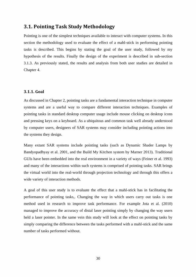
This user study adapted this setup to instead be a 3 × 3 array of nine circles arranged linearly
and equidistantly, as in Figure 3.1 below. Each circle was 12mm in radius and spaced 135mm
apart. The addition of 4 circles along the edges served to help keep the lengths of the travel
between targets to between those for when I was first instructed in using a mahl-stick whilst
still allowing longer distances. The dimensions were chosen as they would keep the area to
within the 300 × 300mm size constraint. These targets were projected onto a wall using a
virtual rear projection technique, as described in greater detail in Section 3.3 below.
32
Figure 3.1: Arrangement and size of the projected targets in the Pointing Task study
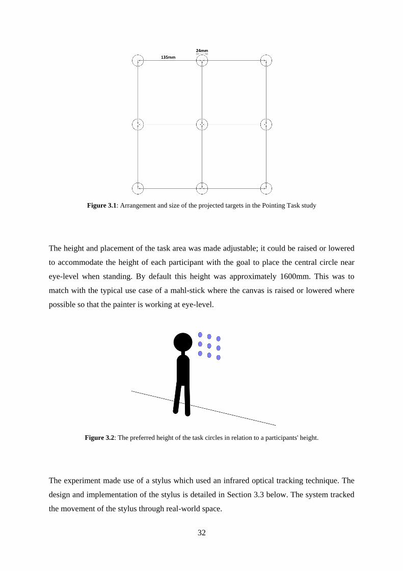
The height and placement of the task area was made adjustable; it could be raised or lowered
to accommodate the height of each participant with the goal to place the central circle near
eye-level when standing. By default this height was approximately 1600mm. This was to
match with the typical use case of a mahl-stick where the canvas is raised or lowered where
possible so that the painter is working at eye-level.
Figure 3.2: The preferred height of the task circles in relation to a participants' height.
The experiment made use of a stylus which used an infrared optical tracking technique. The
design and implementation of the stylus is detailed in Section 3.3 below. The system tracked
the movement of the stylus through real-world space.

33
Participants were given a brief description of mahl-sticks, shown how to use them, and were
given the opportunity to practice using the stick and the stylus before the experiment began.
Only once the participant indicated they were ready did the user study begin.
a)
b).
Figure 3.3: The participant performing the task without the stick (a) and with the stick (b)
All of the 9 points were coloured in light blue (RGB: 127, 127, 255) by default. The
designated target was coloured yellow (RGB: 255, 255, 0). This provided a stark visual
contrast for the target and was clear in the environment. All 9 targets were projected at all
times. After completing each block the circles would turn grey for 5 seconds (RGB: 127, 127,
127), indicating to the participant that the stage had been completed.
Each block was comprised of 35 tasks; each task being defined by an origin point and a
destination point. The path for each task was restricted to only vertical, horizontal, and 45º
angled paths so as to remain consistent with the Steering Task Study, as described in the next
section. There were a total of 56 valid paths; the paths were randomly chosen for each block
for each participant and no path would repeat in one block. This would provide a wide a
range of paths with which to compare across all results. Originally it was planned for
participants to complete all 56 paths each block. However initial testing revealed that it was
too fatiguing on the participants arms when performed in succession with the Steering Task
study, and so the number was reduced to 35 which still resulted in a large number of paths to
compare blocks against.
For each task one circle would be highlighted at random (Figure 3.4, a). When the user
positioned the tip of the stylus over that target, another circle along a valid non-repeating path
would be highlighted at random (Figure 3.4, b). These paths were pre-programmed into an

34
array and selected at random, to ensure that no origin point could be selected that had already
exhausted all possible paths.
a)
b).
Figure 3.4: a) An origin point chosen at random. b) Once the participant has placed the tip of the stylus over the
origin point, a destination point is displayed.
After each task is completed another origin point was chosen at random; it may or may not
have been the same as the destination point. To prevent any possible confusion to the
participants, after completing a task the next origin point was not highlighted until the user
removed the tip of the stylus from the wall.
For each task in each block the system recorded several items of data: the participant's
number; whether or not they used a mahl-stick; the block number (starting at 0); the origin
point for the task; destination point; the time it took to complete the task; and, how far they
were from the centre of the destination point when they completed the task recorded in
millimetres. This distance can be used to rate the average accuracy in completing the pointing
tasks as the closer they were to the absolute centre of the target the more accurate they were.
This measurement could not be used to rate the absolute accuracy of each individual task as
the stylus' position jittered in the system to within approximately 2mm from its actual
position. This jitter was accounted for in the design (see Section 3.3 below) of the
experiment, and would average out in a large enough population. This information is enough
to evaluate the mahl-stick in terms of Fitts' Law as well as obtain data on a learning effect.
After completing all four blocks, the user was asked to fill in a short survey asking their age,
sex, and past experience with a mahl-stick. They were also asked to rate from 1 to 5 how
easy, accurate, and fast they felt they were in completing the tasks with and without a mahl-

35
stick. Finally they were asked to rate their preference in using a mahl-stick in performing
pointing tasks.
Also during the task participants were assessed on which technique they used to hold the
stick and how they were coping with arm fatigue.

36
3.2. Steering Task Study Methodology
Steering is another simple technique available to interact with computer systems. In this
section the methodology used to evaluate the effect of a mahl-stick in performing steering
tasks is described. This is begun by stating the goal of the user study followed by my
hypothesis of the results. Finally the design of the experiment is described in sub-section
3.2.3. As previously stated the results and analysis are detailed in Chapter 4.
3.2.1. Goal
As discussed in Chapter 2, steering tasks are another fundamental interaction technique in
computer systems. A common example in desktop computing of a steering task is navigating
a menu in a program. Another example of a steering task is to draw a line through a specific
tunnel.
Drawing lines is used extensively in creative and design processes and SAR has been
demonstrated capable of benefiting existing workflows. For example, the Digital Airbrushing
and Augmented Foam Sculpting systems contain drawing or steering tasks (Marner 2013).
Drawing tasks are also used in entertainment; for example the IncreTable (Leitner et al. 2008)
is a mixed-reality game that demonstrates SAR applications in this field.
A goal of this user study is to evaluate the effect that a mahl-stick has in facilitating the
performance of steering tasks to both draw lines and navigate systems. As far as I can
determine this is the first research of this type on mahl-sticks.
3.2.2. Hypothesis
My hypothesis for this user study was that the mahl-stick will offer an improvement to the
accuracy of simple drawing tasks at the expense of speed. In painting and signwriting the
mahl-stick offers advantages by supporting the painter's brush hand to make precise and even
strokes. However doing so is noticeably slower than drawing freehand. These benefits should
be able to translate to a mixed reality drawing context.

37
3.2.3. Steering Task Study Design
This user study was designed to be as similar to the Pointing task user study as possible. The
same arrangement, size and spacing of targets was retained as in Figure 3.5 below. Users
were asked to perform four blocks of steering tasks: two with a mahl-stick and two without,
and like in the Pointing task study they were interleaved. It was randomly determined
whether to start with or without the mahl-stick.
Figure 3.5: Arrangement and size of the projected targets in the Pointing Task study
This study had the same setup and environmental design as the pointing task user study: two
projectors overlapping their projections to create a virtual rear projected display. The infrared
optically-tracked stylus and mahl-stick were retained and the tracking system was no
different. The height of the circles was also adjustable to suit the height of the participant.
Each block was comprised of 35 tasks, comprised of the 56 randomly selected path
orientations as in the pointing study: constricted to those routes that are either vertical,
horizontal, or at a 45º angle. Angle has been shown to have an important effect in completing
steering tasks (Grossman and Balakrishnan 2005). Direction is important when using a mahl-
stick: downward strokes are generally considered the easiest to make, and horizontally it is
easier to make strokes in the same direction as you are handed. By limiting the paths to those
angles it would be easier to analyse path directions if something were significant was found.
Restricting to those angles also allows potential comparisons to be made regarding the effect
length played in performing those tasks.
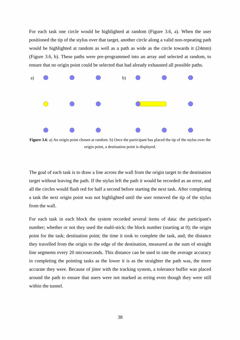
38
For each task one circle would be highlighted at random (Figure 3.6, a). When the user
positioned the tip of the stylus over that target, another circle along a valid non-repeating path
would be highlighted at random as well as a path as wide as the circle towards it (24mm)
(Figure 3.6, b). These paths were pre-programmed into an array and selected at random, to
ensure that no origin point could be selected that had already exhausted all possible paths.
a)
b).
Figure 3.6: a) An origin point chosen at random. b) Once the participant has placed the tip of the stylus over the
origin point, a destination point is displayed.
The goal of each task is to draw a line across the wall from the origin target to the destination
target without leaving the path. If the stylus left the path it would be recorded as an error, and
all the circles would flash red for half a second before starting the next task. After completing
a task the next origin point was not highlighted until the user removed the tip of the stylus
from the wall.
For each task in each block the system recorded several items of data: the participant's
number; whether or not they used the mahl-stick; the block number (starting at 0); the origin
point for the task; destination point; the time it took to complete the task, and; the distance
they travelled from the origin to the edge of the destination, measured as the sum of straight
line segments every 20 microseconds. This distance can be used to rate the average accuracy
in completing the pointing tasks as the lower it is as the straighter the path was, the more
accurate they were. Because of jitter with the tracking system, a tolerance buffer was placed
around the path to ensure that users were not marked as erring even though they were still
within the tunnel.

39
a)
b).
Figure 3.7: A participant in the steering task study, with a mahl-stick (a) and without (b).
After completing all four blocks, the user was asked to fill in a short survey asking their age,
sex, and past experience with a mahl-stick. They were also asked to rate from 1 to 5 how
easy, accurate, and fast they felt they were in completing the tasks with and without a mahl-
stick. Finally they were asked to rate their preference in using a mahl-stick in performing
steering tasks.
During the task participants were assessed on which technique they used to hold the stick and
how they were coping with arm fatigue.
Originally the paths for the task were much smaller: the radius of the circles was 7.5mm and
the width of the tunnels was 15mm. After running an initial participant it became clear that
this was too difficult for members of the general public to perform. For the need to obtain
actual data which was not almost entirely a sequence of errors, the size of the circles and the
width of the tunnels was increased to 24mm.

40
3.3. User Study Environment
The same setup was used for both the Pointing and Steering task user studies, in the same
location. The same mahl-stick and stylus were also used. This section describes the theory
and processes used to calibrate the system to run the user studies, and the details describing
the construction of the stylus and mahl-stick. The system used the SAR software modules of
the Wearable Computer Lab at the University of South Australia, with several modifications
made to adapt to the system to what was required. The first section describes the projection
system used and the second section describes the tracking system. The stylus and mahl-stick
are then described in detail. The module created to combine these elements and manage the
user study is then described.
3.3.1. Projection System
SAR uses projectors to alter the appearance of objects in real-time. One of the more
immediate problems when using projectors is the risk of shadow occlusion. If one object is
between the projector and the surface it is projecting onto, a shadow is cast and that part of
the image is lost. This was an issue in the pointing and steering task studies: as the user
would be performing tasks on a projected wall, no matter where a projector is positioned
behind the participant there will be always be shadow occlusion. This is demonstrated in
Figure 3.8 below. If it is placed at an angle oblique enough so that the participant's body did
not cause occlusion, the image would be so distorted that accuracy and image quality would
be sacrificed. When the stylus came in contact with the surface, the image would be occluded
anyway.
Figure 3.8: Use of a single projector would have left a large occluded area where the circles would not be
visible without the participant moving out the way, greatly hindering performance of pointing and steering tasks

41
To overcome this issue a virtual rear projection technique was used, as described by Summet
et al. (2005). This uses several projectors placed at different oblique angles away from the
surface of a wall, which are calibrated to project the same image onto the same section of
wall. This is done so that if a person occludes the projection from one projector, the image
can still be seen as the other projections are not being occluded.
This is demonstrated in Figure 3.9: (a) shows the occlusion from a projector to the left, and
(b) the occlusion from a projector to the right. As described above, if only one of projector is
used, part of the image is occluded. However when two projectors are projecting
simultaneously from different locations (c) the resulting image is still clear as if the user is
occluding one projector, the image from another projector is very likely still clear. This made
it unlikely that any one target could be fully occluded.
a)
b).
c)
Figure 3.9: The images from left (a) and right (b) projectors individually showing the occlusion (the greyed out
area), and the combined image from both projectors (c).
There are several reasons why this projection system was chosen over other methods. As
stated, if only a single projector was used shadow occlusion would have been a significant
issue. No matter where it was placed the participant would occlude it at some point when
performing the user study which would have introduced errors into the results: users would
have been forced to either guess where the targets were or move around considerably
affecting the resulting time to complete each task.

42
The use of a Smart Board was also inappropriate this purpose. Whilst this would have solved
all issues with shadow occlusion, a mahl-stick is used to support the drawing hand.
Depending on the force the participant placed on the stick, damage to the board surface could
have occurred. The goal of this study was to examine mahl-sticks in a SAR context: a rear
projection technique such as a Smart Board was not a SAR-based solution to the occlusion
issue.
Two projectors were deemed sufficient to project onto the wall. These were positioned 3
metres above floor level, 2.5 metres away from the wall. Both projectors were placed off-
from-centre to the targeted projection area to help reduce shadow occlusion. A colour-
banding technique was used to calibrate both projectors automatically. A digital camera was
set back from the wall positioned so that the full images from both projectors were visible. A
sequence of black and white bands were projected through each projector. The camera
captured these bands and from the resulting data the intrinsic and extrinsic properties of each
projector were calculated.
Figure 3.10: Even though his hand occludes the light from one projector, the path can still be seen as the other
projector is not occluded.
An 1135 × 976mm rectangular level area was marked out onto the wall. A crosshair was
moved through the projected image to record the corners of this area, relative to the
projections. Doing this allowed the projections to be cropped and keystoned to align to this
area, scaled to the default OpenGL floating point scale of 0.0 to 1.0 in both the x and y axes.
It was trivially simple to change this scale to 0 - 1135 in the x-axis and 0 - 976 in the y-axis to
match the real-world scale, so that the size of image elements could be set to millimetres and
that the units could also match the tracking system, described in the next section.

43
3.3.2. Tracking System
An infrared optical tracking system was chosen to track the stylus. Infrared tracking was
readily available in the Wearable Computer Lab and supported in the pre-existing software
modules. From an implementation standpoint a robust optical tracking solution already had
much of the groundwork for it laid and it would have been less effort to get it to work in the
modules. As described in Chapter 2, Section 3, optical tracking is fast, has high update rates
and is unaffected by surrounding electromagnetic interference. Optical tracking is also widely
used in SAR already. However it suffers from line-of-sight issues as the optical markers need
to be visible from the tracking cameras.
Other tracking solutions were dismissed. The laboratory environment the user study was run
in has many electronic devices situated through it and man cables running through the floor,
ceiling and walls. Magnetic trackers could not be used in such an environment as the
potential for electromagnetic interference would have been too great, and obtaining another
environment to run such a study would have been too difficult. Acoustic trackers are slower
than optical trackers but still suffer from line-of-sight issues, making them an inferior option.
Devising a mechanical tracking solution could potentially have been expensive and a difficult
engineering problem: devising a hand-held stylus that could be moved easily, be held by
people comfortably as well as used in conjunction with a mahl-stick without impeding the
participant's sight.
Combining optical tracking with inertial tracking was considered, as inertial trackers have
high update rates and are unaffected by the line-of-sight issues that impede optical tracking.
By embedding a 6 degree-of-freedom accelerometer and gyroscope (sometimes called an
Inertial Measurement Unit), which tracks movement along 3 axes and the rotation forces
around each, inside the stylus it would have been possible to keep track of the stylus in
situations where line-of-sight was broken. But this leads to an inevitable problem - when
optical and inertial trackers give conflicting tracking information how does one know which
one is reporting correct information, if at all? Also out of concerns for the physical
construction of the stylus (described in the next sub-section 3.3.3) the idea of combining
optical and inertial tracking was abandoned.
The OptiTrack motion capture software created by NaturalPoint was used to register the
position and angle of the stylus. Infrared retro-reflective tape was wrapped around 4 marker

44
spheres attached to the stylus. Five Flex 3 motion capture cameras were positioned around
the projection area, as shown in Figure 3.11 below: one placed to the left looking between the
participant and the wall, and four suspended from the ceiling look down towards the user.
Figure 3.11: The arrangement of Flex 3 cameras positioned around the projection area.
VRPN, a device-independent networking protocol to track peripherals in VR applications,
was used to communicate the tracked data from the OptiTrack system into the Wearable
Computer Lab's SAR modules. The points from OptiTrack were originally based around a
coordinate system set by the positions of the cameras. These camera space coordinates were
transformed to match the projector's coordinate system: the x-axis was transformed along the
length of the projection, the y-axis was transformed along the height of the projection, and the
z-axis was transformed so that it emerged outwards from the wall perpendicular towards the
participant. The scale of the coordinates changed to match the size of the projection plane,
with the origin (0, 0, 0) set to be the bottom left-hand corner of the wall.
Figure 3.12: The final coordinate system of both projectors and the camera space

45
3.3.3. Stylus
It was determined that a stylus was the optimal way to interact with the system in the pointing
and steering task studies. A stylus is already used as an input device in SAR systems. It is a
useful replacement for a brush in drawing tasks: a stylus is in many ways a simplification of a
brush. A stylus was created for the pointing and steering task studies.
As stated before in the 3.3.2. Tracking section, it was originally intended that the stylus
would make use of both optical tracking through infrared retro-reflective markers mounted
onto it, and inertial tracking through an embedded electronic 6 degree-of-freedom gyroscope
- accelerometer. Whilst being able to correctly determine the position of the stylus when the
inertial and optical tracking were providing conflicting accounts was one concern that
ultimately led to the abandonment of this idea, the resulting size that such a stylus would
have was another serious concern. The stylus had to be small enough to be held in any
participant's hands, whilst at the same time large enough to carry a microcontroller and
accelerometer. This would have resulted in a narrow stylus with a large and overweighted
protrusion to housing electronics at the rear. The 3D printer which would ultimately create
the stylus can only print in a volume 250 × 250 × 250mm. Initial trials of combining two
pieces of 3D printed objects together resulted in breaks when held roughly. It could not be
ensured that trial participants would be gentle with the stylus. With all these concerns the
stylus was simplified to only use optical tracking and was designed to be less than 250mm
long.
Figure 3.13: The final stylus used in the trial

46
The main part of the stylus was created 15mm in diameter and 200mm in length. The tip
extended 18mm and ended in a 3mm rounded cap. Four 14mm spheres were attached at
length from the body of the stylus: one directly from the rear, two at different lengths at 90º
from each other near the back, and one a short distance from the centre. The four spheres
were covered in infrared retro-reflective tape to work with the OptiTrack system. The four
spheres were printed as part of the stylus, and not attached afterwards, to provide additional
rigidity.
3.3.4. Mahl-Stick
There is not set form, size or length a mahl-stick can take; some mahl-sticks can range from
the short to over 4 metres in length. They are usually made of wood though aluminium or any
other rigid and relatively light material can be used. They are often rounded in cross-section
so as to not cause discomfort as the user rests their wrist on a hard edge, though rectangular
and square mahl-sticks exist. Sometimes one end is capped in a protrusion or stopper of some
form, and this end can be wrapped in a cloth or chamois to protect the surface its resting on or
decrease the chance of slippage.
Without a standard form or size, for the purposes of this study a round 20mm diameter pine
mahl-stick 1200mm long was created. This was chosen as it is a length that would suit most
anybody drawing within a 300 × 300mm area, is lightweight and was affordable. One end
was capped in a 50mm diameter sphere, which was 3D printed, so as to not damage the wall
with a sharp edge of the wood. In turn this was wrapped in a piece of cloth to increase grip
with the wall.
Figure 3.14: The mahl-stick used in the user studies

47
4. ANALYSIS
19 participants took part in the combined pointing task and steering task user study, with
participants drawn from the Mawson Lakes campus of the University of South Australia and
the general public. The combined study took approximately 30 minutes to complete. After
completing both the pointing and steering task studies, participants were asked to answer a
questionnaire regarding their opinions of the results.
The pointing task and steering task studies were ran one after another. It was randomly
determined which study the participants started with. It was also randomly determined
whether they would start with using the mahl-stick or not. After completing each block of 5
tasks, a 5 second interval would occur where the stick was swapped in or out. After the first
four blocks were complete, users were given some time to rest if they needed before starting
the other study.
After the first participant was ran, changes were made to both the pointing and steering task
study. The radius of the circles was increased from 7.5mm to 12mm and the width of the
tunnels were made as wide as the new circles. This was done because the initial tunnel width,
15mm, was too narrow for members of the general public to complete. Moving the stylus
outside of the tunnel resulted in an error, and the error rate in the first steering study ran
around 90%. After the size of the elements was increased, no further alterations were made to
the study. Only the results from the remaining 18 participants were analysed.
The research question was to:
...evaluate the effect that a mahl-stick has when performing simple pointing and
steering tasks in Spatial Augmented Reality applications when using a stylus.
As part of this two sub-questions were asked:
To compare how novice and experienced users compare with the use of a mahl-stick
in pointing and steering tasks, and;
what learning effect is observable in using a mahl-stick.

48
Participants were between the ages of 24 and 48. 16 were male and 3 were female. All
participants were right-handed. Only one participant (19) had used a mahl-stick prior to the
commencement of the study. As I was unable to get more participants that had used a mahl-
stick prior to the study, I was unable to obtain enough data to answer the first sub-question.
Over the course of the user study, from observation of the participants and conversation with
them, it became clear that fatigue had a large effect on the performance of pointing and
steering tasks. However as fatigue was not asked about in the survey, the participants
themselves did not write down the level of fatigue they felt they experienced.
The analysis of results is broken into 3 parts: the analysis of the pointing task study results in
section 4.1, the analysis of the steering task study in section 4.2, and an analysis of the
surveys in section 4.3.

49
4.1. Pointing Task User Study
I hypothesised that a mahl-stick could offer no real improvement to accuracy in performing
pointing tasks, and that it would reduce arm fatigue at the cost of making the pointing tasks
slower to perform.
The data recorded for the pointing task study was:
the participant number,
the block number,
whether the mahl-stick was used or not,
the origin point for each task,
the destination point for each task,
the time taken to complete each task, and
the distance from the centre of the destination point.
The origin and destination points allows one to determine the length of each path from origin
to destination, and the direction in which the travel occurred. The distance from the centre of
the destination target provides an indication of the accuracy of the pointing tasks; the greater
it is the less precise they were in selecting the target.
The data for the results is tabled in terms of time in milliseconds, distance from the centre of
the destination point in millimetres, and the total speed for which the task was completed
(calculated from the length of the path for each task divided by the time taken to complete)
measured in millimetres per millisecond, or metres per second. All results were trimmed to be
within 3 standard deviations of the mean, as per the standard practice in Computer Science.

50
Time to Complete Tasks (ms)
1st Block 2nd Block
With Mahl-stick Without Mahl-stick With Mahl-stick Without Mahl-stick
Mean ( ) SD (σ) Mean ( ) SD (σ) Mean ( ) SD (σ) Mean ( ) SD (σ)
2 1428.286 331.598 1084.324 309.115 1292.088 281.678 944.441 222.654 3 844.382 261.594 776.735 212.854 764.941 151.030 711.914 82.224 4 1443.543 499.571 1161.706 486.100 1182.971 243.467 984.352 327.205
5 889.829 172.797 793.600 103.469 802.257 103.268 716.486 65.7407 6 928.303 1413.740 816.576 235.357 859.177 245.852 779.212 147.100
7 1130.629 232.734 1037.588 584.103 1067.500 334.131 1076.714 149.868 8 1068.714 242.178 884.152 281.442 913.485 548.814 790.265 176.229
9 713.265 215.157 696.515 246.127 654.500 197.592 646.353 102.163 10 824.559 170.685 886.235 568.080 909.618 402.890 771.177 182.635
11 780.971 200.275 861.114 260.098 863.735 277.758 826.823 329.517 12 896.257 227.646 916.735 565.147 968.571 397.417 686.765 196.434 13 854.618 211.826 783.794 189.721 728.486 444.450 919.879 105.824
14 1025.471 248.511 952.235 404.607 1003.118 240.338 846.294 153.696 15 1349.559 596.214 994.382 363.534 1166.441 340.281 765.559 192.237
16 1049.971 349.480 817.029 102.768 937.697 159.293 823.229 118.821 17 1531.618 941.112 892.471 182.214 1341.086 376.428 1007.000 208.529
18 737.371 166.772 683.677 161.239 648.412 112.07 707.114 606.433 19 821.441 152.457 970.857 120.255 759.457 121.189 760.257 142.588 ALL 1066.551 581.164 916.840 362.186 976.975 354.604 826.130 256.806
Distance from Centre of Pointing Target (mm)
1st Block 2nd Block
With Mahl-stick Without Mahl-stick With Mahl-stick Without Mahl-stick
Mean ( ) SD (σ) Mean ( ) SD (σ) Mean ( ) SD (σ) Mean ( ) SD (σ)
2 4.457 3.475 3.588 2.289 3.882 2.904 4.324 2.529 3 8.206 4.482 7.353 4.132 10.412 4.736 8.343 4.665
4 8.486 4.736 8.824 5.035 9.171 5.079 10.265 4.937 5 6.286 4.322 5.800 2.743 5.286 3.553 7.686 3.279
6 7.818 4.426 7.424 4.341 9.088 4.943 8.485 3.909 7 6.857 4.074 5.118 3.311 8.824 4.965 5.143 3.549
8 6.343 3.531 6.848 3.733 8.212 4.378 5.265 2.944 9 10.382 4.467 7.121 4.759 10.029 4.649 7.118 4.098
10 8.647 4.125 7.559 3.615 7.294 4.120 5.618 3.369 11 9.382 4.979 7.457 3.921 7.324 3.956 6.765 3.483 12 9.343 4.556 11.471 3.936 10.543 4.931 8.529 4.619
13 8.618 4.996 7.294 4.253 7.200 4.549 8.061 3.917 14 8.441 5.121 7.176 4.530 7.853 4.740 9.029 5.042
15 9.676 4.371 7.676 3.936 8.176 4.232 9.794 4.821 16 8.059 5.396 8.206 4.444 8.152 4.684 6.486 3.899
17 8.029 5.621 7.618 4.649 9.514 5.299 6.529 4.473 18 9.571 4.698 8.147 4.178 8.853 5.057 10.114 4.741 19 8.382 4.230 6.743 3.791 6.543 3.868 8.143 4.532
ALL 8.119 4.720 7.314 4.320 8.243 4.776 7.414 4.367

51
Overall Speed to Complete Tasks (ms-1)
1st Block 2nd Block
With Mahl-stick Without Mahl-stick With Mahl-stick Without Mahl-stick
Mean ( ) SD (σ) Mean ( ) SD (σ) Mean ( ) SD (σ) Mean ( ) SD (σ)
2 0.139 0.043 0.181 0.063 0.143 0.040 0.216 0.069 3 0.242 0.081 0.260 0.083 0.246 0.071 0.276 0.086 4 0.148 0.048 0.160 0.047 0.168 0.054 0.204 0.058
5 0.229 0.066 0.251 0.069 0.224 0.057 0.257 0.089 6 0.212 0.082 0.240 0.077 0.236 0.072 0.265 0.081
7 0.177 0.050 0.192 0.063 0.186 0.059 0.193 0.068 8 0.183 0.059 0.223 0.065 0.211 0.067 0.250 0.086
9 0.271 0.086 0.289 0.102 0.295 0.090 0.305 0.097 10 0.218 0.061 0.256 0.105 0.224 0.078 0.266 0.080
11 0.243 0.080 0.244 0.075 0.241 0.077 0.254 0.096 12 0.219 0.061 0.245 0.104 0.207 0.085 0.295 0.088 13 0.240 0.065 0.247 0.069 0.260 0.072 0.217 0.079
14 0.207 0.052 0.219 0.077 0.207 0.064 0.223 0.074 15 0.153 0.052 0.197 0.064 0.159 0.036 0.257 0.088
16 0.184 0.066 0.254 0.084 0.215 0.064 0.244 0.080 17 0.137 0.050 0.227 0.079 0.152 0.047 0.185 0.057
18 0.266 0.082 0.273 0.089 0.291 0.087 0.286 0.104 19 0.250 0.076 0.253 0.087 0.248 0.075 0.265 0.084 ALL 0.204 0.077 0.231 0.085 0.212 0.078 0.248 0.087
Overall participants tended to become faster across the two blocks, both with and without the
stick. Performance was greater without the use of the mahl-stick than with it. There was not a
significant difference in the accuracy of pointing tasks. A repeated measures ANOVA was
performed on the Time to Complete Tasks, the Distance from the Centre of Pointing Target,
and the Overall Speed to Complete Tasks. No results of significance were detected (p > 0.05),
and no learning effect was observed in using the mahl-stick.
Below the Index of Difficulty for the four possible line lengths are calculated, using the
formulae of the Shannon IDS, Welford IDW, and Yang & Xu's IDYX formulations. The size of
the targets did not change from 24mm, only the distance between targets varied. HV1 and
HV2 are paths that existed either vertically or horizontally, one or two targets away
respectively. D1 and D2 are diagonal paths at 45º, one or targets away respectively as well.
The length L of the lines are given in millimetres.
L IDS IDW IDYX
HV1 135 2.728 2.615 1.392 HV2 270 3.615 3.555 2.087
D1 190.918 3.163 3.080 1.721 D2 381.838 4.080 4.036 2.484

52
4.2. Steering Task User Study
My hypothesis for this user study was that the mahl-stick will offer an improvement to the
accuracy of simple drawing tasks at the expense of speed. In painting and signwriting the
mahl-stick offers advantages by supporting the painter's brush hand to make precise and even
strokes, though it is noticeably slower than drawing freehand. These benefits should translate
to a mixed reality drawing context substituting a stylus for the brush.
The data recorded for the pointing task study was:
the participant number,
the block number,
whether the mahl-stick was used or not,
the origin point for each task,
the destination point for each task,
the time taken to complete each task,
the length of the line drawn, measured in line segments every 20ms, and
whether the task ended in error or not.
As with the pointing task study, the origin and destination points allows the length of the
ideal path and the direction to be calculated. The length of the line drawn was useful for
calculating the accuracy of the line drawn. The shorter the line drawn the more accurate it
had to be, and likewise the longer the line the less accurate.
The data for the results is tabled in terms of time in milliseconds, distance from the centre of
the destination point in millimetres, and the total speed for which the task was completed
(calculated from the length of the path for each task divided by the time taken to complete)
measured in millimetres per millisecond, or metres per second.
All results were trimmed to be within 3 standard deviations of the mean, as per the standard
practice in Computer Science. Due to occlusions in the tracking system, not all errors were
caused by users leaving the bounds of the tunnel. If the user held or moved the stylus in such
a way as to occlude one of the markers, the OptiTrack software lost track of the real-world
position of the stylus and assumed it was elsewhere. If this occurred whilst drawing a line, the
user study module would obtain the data and assume the stylus had left the bounds of the

53
tunnel, recording an error. Because it was impossible to state with certainty which errors were
user-caused and which weren't, all errors were removed from the analysis of results.
Time to Complete Tasks (ms)
1st Block 2nd Block
With Mahl-stick Without Mahl-stick With Mahl-stick Without Mahl-stick
Mean ( ) SD (σ) Mean ( ) SD (σ) Mean ( ) SD (σ) Mean ( ) SD (σ)
2 1302.739 275.838 1150.371 317.176 1770.364 613.084 1221.030 382.410 3 901.344 156.170 758.645 120.059 830.667 133.231 913.394 112.230 4 1581.833 353.802 1448.615 335.487 1478.400 341.619 1215.231 308.111
5 1496.576 436.753 1221.091 377.507 1378.571 322.489 1074.559 298.623 6 1320.645 319.513 800.879 143.357 1057.280 325.454 879.231 189.237
7 1713.259 564.150 1423.452 356.833 1284.030 328.239 1461.250 239.264 8 1528.435 548.967 1072.000 403.191 1571.583 420.711 1161.742 237.122
9 883.276 176.258 724.097 109.245 773.267 151.285 794.065 136.249 10 1187.040 208.816 1177.412 260.919 1332.368 327.546 1143.897 338.943 11 753.960 164.355 754.241 89.724 825.607 306.884 824.963 102.471
12 1665.929 532.312 844.136 136.248 1207.935 409.317 791.419 168.784 13 833.424 101.723 786.786 99.886 871.800 126.742 764.533 101.025
14 1565.567 344.554 1317.629 271.847 1022.656 307.092 1461.240 129.986 15 1333.462 270.804 1102.885 234.449 1465.281 256.199 1055.000 262.240
16 2904.045 765.364 1165.857 339.598 1336.273 939.710 916.333 122.821 17 3430.294 1673.309 1560.759 380.863 3547.136 1153.255 1441.517 610.513
18 868.903 139.350 774.382 100.224 749.417 154.898 886.433 84.411 19 2524.656 729.694 1143.697 433.485 1219.824 211.054 956.788 237.469 ALL 1497.259 859.701 1073.397 381.451 1338.072 707.945 1026.209 334.117
Length of Line Drawn (mm)
1st Block 2nd Block
With Mahl-stick Without Mahl-stick With Mahl-stick Without Mahl-stick
Mean ( ) SD (σ) Mean ( ) SD (σ) Mean ( ) SD (σ) Mean ( ) SD (σ)
2 1.232 0.150 1.202 0.078 1.286 0.203 1.233 0.125 3 1.226 0.099 1.239 0.111 1.199 0.141 1.221 0.111 4 1.288 0.192 1.241 0.135 1.445 0.224 1.338 0.353
5 1.246 0.109 1.374 0.185 1.353 0.150 1.249 0.121 6 1.368 0.284 1.242 0.092 1.307 0.197 1.281 0.146
7 1.243 0.140 1.311 0.188 1.189 0.069 1.226 0.081 8 1.452 0.293 1.343 0.204 1.231 0.129 1.245 0.104
9 1.250 0.116 1.226 0.097 1.267 0.169 1.179 0.092 10 1.265 0.112 1.208 0.131 1.259 0.154 1.206 0.098 11 1.211 0.097 1.217 0.114 1.275 0.160 1.216 0.111
12 1.350 0.202 1.263 0.100 1.232 0.118 1.285 0.166 13 1.238 0.147 1.314 0.185 1.246 0.186 1.213 0.097
14 1.254 0.179 1.278 0.141 1.238 0.162 1.288 0.114 15 1.336 0.155 1.345 0.180 1.379 0.228 1.299 0.204
16 1.938 0.714 1.220 0.124 1.273 0.527 1.260 0.110 17 1.772 0.508 1.328 0.249 1.844 0.397 1.361 0.231
18 1.284 0.238 1.261 0.175 1.302 0.134 1.280 0.230 19 1.587 0.427 1.226 0.146 1.253 0.169 1.219 0.132 ALL 1.348 0.319 1.268 0.158 1.310 0.253 1.248 0.161

54
Speed to Complete Tasks (ms-1)
1st Block 2nd Block
With Mahl-stick Without Mahl-stick With Mahl-stick Without Mahl-stick
Mean ( ) SD (σ) Mean ( ) SD (σ) Mean ( ) SD (σ) Mean ( ) SD (σ)
2 0.146 0.029 0.174 0.036 0.124 0.028 0.168 0.030 3 0.232 0.064 0.242 0.061 0.259 0.049 0.221 0.065 4 0.116 0.021 0.147 0.036 0.153 0.042 0.165 0.026
5 0.137 0.031 0.186 0.034 0.161 0.032 0.187 0.035 6 0.164 0.034 0.260 0.064 0.191 0.035 0.224 0.047
7 0.134 0.030 0.148 0.035 0.174 0.024 0.129 0.032 8 0.166 0.035 0.216 0.050 0.133 0.026 0.161 0.030
9 0.230 0.048 0.274 0.066 0.259 0.060 0.254 0.057 10 0.153 0.032 0.169 0.041 0.162 0.025 0.181 0.039
11 0.241 0.059 0.256 0.055 0.240 0.069 0.269 0.071 12 0.130 0.027 0.225 0.047 0.186 0.031 0.260 0.054 13 0.229 0.058 0.242 0.060 0.229 0.052 0.253 0.061
14 0.136 0.031 0.172 0.038 0.194 0.030 0.144 0.049 15 0.163 0.028 0.181 0.036 0.151 0.028 0.191 0.034
16 0.127 0.035 0.181 0.033 0.164 0.050 0.202 0.046 17 0.078 0.025 0.148 0.040 0.081 0.022 0.148 0.028
18 0.245 0.060 0.270 0.064 0.296 0.061 0.248 0.059 19 0.113 0.040 0.196 0.066 0.170 0.039 0.236 0.057 ALL 0.168 0.064 0.206 0.066 0.178 0.062 0.211 0.063
As with the pointing task, participants tended to become faster across the two blocks, both
with and without the stick. As with the pointing task study, performance was greater without
the use of the mahl-stick than with it. A repeated measures ANOVA was performed on the
Time to Complete Tasks, the Distance from the Centre of Pointing Target, and the Overall
Speed to Complete Tasks. No results of significance were detected (p > 0.05), and again no
learning effect was observed in using the mahl-stick.
Below the Index of Difficulty for the four possible line lengths are calculated, using Accot &
Zhai's formulation IDAZ. Given that the path widths were constant the entire length and
entirely straight, there was no benefit to be gained by using other formulations. The size of
the targets did not change from 24mm, only the distance between targets varied. HV1 and
HV2 are paths that existed either vertically or horizontally, one or two targets away
respectively. D1 and D2 are diagonal paths at 45º, one or targets away respectively as well.
The length L of the lines are given in millimetres.
L IDAR
HV1 135 5.625 HV2 270 11.250
D1 190.918 7.955 D2 381.838 15.910

55
4.3. Qualitative Results
In evaluating the use of a mahl-stick in performing pointing and steering tasks, qualitative
information from participants was gathered regarding their opinions on how mahl-sticks
affected performance. This data was obtained in two ways. Whilst the participants were
performing the tasks, Information of their fatigue, how they used the mahl-stick, and which
hand they held the stylus with were also recorded. This information is explored in sub-section
4.3.1. After completing both the pointing and steering tasks, participants were asked fill out a
questionnaire asking for some defining information, their past experience with a mahl-stick,
and their opinions and preference as to the performance of the mahl-stick in pointing and
steering tasks. The questionnaires are analysed in sub-section 4.3.2.
4.3.1. Observations of Participants
Participants were observed on how they used the stick to complete the pointing and steering
tasks, and how fatigued they were by completion. This information is tabled below. Fatigue is
measured in three categories: Low Fatigue, Some Fatigue, and High Fatigue. Some
participants stated they did not have issue with fatigue in performing the study, and these
people are listed under Low Fatigue. On the other hand, some participants said they had a lot
of fatigue in performing the pointing and steering tasks and are listed under High Fatigue.
Some Fatigue is a category for those in between. It's possible that some of those listed as Low
Fatigue should be listed higher due to understatement by participants.
Pointing Technique Steering Technique Fatigue
2 Pickup at start; changed to Slide Slide High Fatigue 3 Pickup Slide Some Fatigue
4 Pickup Pickup Low Fatigue 5 Slide Pivot Low Fatigue
6 Slide Slide Some Fatigue 7 Slide Slide Some Fatigue 8 Slide Slide Low Fatigue 9 Pivot Pivot Low Fatigue 10 Slide Slide Some Fatigue
11 Slide Slide High Fatigue 12 Slide Slide and Pivot Low Fatigue 13 Slide and Pivot Slide and Pivot Low Fatigue 14 Pickup and Slide Pickup and Slide High Fatigue
15 Pivot Pivot Some Fatigue 16 Pickup Ruler to start; changed to Pickup High Fatigue 17 Pivot Pivot Some Fatigue
18 Pivot Pivot Low Fatigue 19 Slide and Pivot Slide and Pivot Low Fatigue

56
Participants used the mahl-stick in different ways. Pickup refers to the motion of taking the
mahl-stick away from the wall for every task and moving it into position. Slide is when the
hand rested on the mahl-stick in an unmoving position, and the stick and hand slid across the
surface of the wall. Pivot is when the end of the mahl-stick was held in place, and the stick
was rotated and the hand slid across it to complete the tasks. Slide and Pivot refers to a fluid
motion of both sliding the mahl-stick across the surface of the wall whilst also rotating it to
affect the reach of the height. Pickup and Slide refers to the motion of picking up the mahl-
stick to get to the start of the task, and then sliding into position to complete it. One
participant started by using the mahl-stick as a ruler and not a support for the hand.
Only two participants changed the way they used the stick in the middle of either of the
studies: number 2 changed from a Pickup technique to a Slide technique during the pointing
task study, and number 16 changed from the very slow and fatiguing Ruler technique to a
Pickup technique during the steering tasks. Some participants used a different technique for
each of the studies. Number 3 changed from a Pickup technique when pointing to a Slide
technique when steering; number 5 changed from Pivot when steering to Slide when pointing;
number 12 changed from Slide and Pivot when steering to Slide when pointing.
Pickup is a slow and fatiguing way to use the mahl-stick. Of those to use the stick in this
manner, three stated they had a lot of fatigue (3, 14, 16: High Fatigue), one stated they were
getting fatigued after the first study was completed (3: Some Fatigue), and one reported
suffering no arm fatigue at all (4: Low Fatigue). The only other participant that reported
being very sore after completing the studies used the Slide technique, but stated they get very
sore writing on a whiteboard and avoided do so where possible.

57
4.3.2. Questionnaire Results
After completing both the pointing and steering tasks, participants were asked to complete a
questionnaire asking their age; gender; past experience with mahl-sticks; how easy, accurate
and fast they thought it was to complete both tasks with and without the mahl-stick; and their
preference for using the mahl-stick to complete tasks. Past experience was given the options:
I have never used one before (N)
I have some past experience (Y-)
I use one regularly (Y+)
How easy, accurate and fast they felt it was to complete the tasks was rated on a nominal
scale 1 to 5 with 1 marked as difficult, inaccurate and slow, and 5 marked as easy, accurate
and fast. The preference for using a mahl-stick for the tasks was rated on a nominal scale 1 to
5 with 1 marked with and 5 marked without.
Questionnaire Results
Age
Gen
der
Have U
sed
Mah
l-st
ick
Pri
or
Ease
-
Poin
tin
g W
ith
ou
t
Ease
-
Poin
tin
g W
ith
Ease
- S
teer
ing W
ith
ou
t
Ease
- S
teer
ing W
ith
Acc
ura
cy -
Poin
tin
g
Wit
hou
t
Acc
ura
cy -
Poin
tin
g W
ith
Acc
ura
cy -
Ste
erin
g W
ith
ou
t
Acc
ura
cy -
Ste
erin
g W
ith
Sp
eed
- P
oin
tin
g W
ith
ou
t
Sp
eed
- P
oin
tin
g W
ith
Sp
eed
- S
teer
ing W
ith
ou
t
Sp
eed
- S
teer
ing W
ith
Pref
eren
ce -
Poin
tin
g T
ask
s
Pref
eren
ce -
Ste
erin
g T
ask
s
2 29 M N 5 3 3 4 5 4 3 4 5 3 3 3 4 2 3 40 M N 5 3 5 2 5 4 5 4 5 2 4 1 5 4
4 28 F N 5 5 3 4 4 5 3 4 5 3 4 3 3 2 5 28 M N 5 4 5 4 5 5 5 5 5 3 5 3 5 4
6 24 M N 2 3 2 3 4 4 4 4 5 4 5 4 2 2 7 33 F N 5 4 5 2 4 4 4 2 5 4 4 2 5 5
8 33 M N 3 3 5 3 5 5 5 3 5 3 5 3 4 4 9 24 M N 5 5 3 2 4 4 3 3 5 3 4 3 3 3 10 30 M N 5 2 5 2 4 4 4 4 5 2 5 2 3 3
11 27 M N 4 5 4 4 4 4 5 4 5 3 5 4 4 2 12 27 M N 5 4 4 5 5 4 4 5 5 4 5 4 5 1
13 27 M N 5 4 4 5 5 5 4 5 5 4 4 4 4 2 14 40 M N 5 4 5 4 4 4 4 4 5 4 5 4 3 3
15 24 M N 5 3 3 4 5 4 3 4 5 4 3 3 4 2 16 48 F N 4 3 4 1 5 5 5 3 5 4 5 2 5 4
17 25 M N 5 2 4 2 5 5 4 4 4 2 4 2 5 5 18 26 M N 5 4 4 3 5 5 3 3 5 4 5 4 4 3 19 26 M Y- 5 5 5 5 4 4 4 4 5 4 5 4 3 1

58
Means of Survey Results
min max Mean ( ) SD (σ)
Age 24 48 29.944 6.611
Ease - Pointing Without 2 5 4.611 0.850 Ease - Pointing With 2 5 3.667 0.970
Ease - Steering Without 2 5 4.056 0.938 Ease - Steering With 1 5 3.278 1.227
Accuracy - Pointing Without 4 5 4.556 0.511
Accuracy - Pointing With 4 5 4.389 0.502 Accuracy - Steering Without 3 5 4.000 0.767
Accuracy - Steering With 2 5 3.833 0.786
Speed - Pointing Without 4 5 4.944 0.236 Speed - Pointing With 2 4 3.333 0.767
Speed - Steering Without 3 5 4.444 0.705 Speed - Steering With 1 4 3.056 0.938
Preference - Pointing 2 5 3.944 0.938
Preference - Steering 1 5 2.889 1.231
On average participants thought that the mahl-stick made pointing and steering tasks harder,
less accurate and slower. When asked to rate their preference for using the stick for pointing
tasks, participants overwhelmingly came out against it. This result was as hypothesised: for
pointing tasks alone a mahl-stick can only slow a user down and block their line of sight, and
the added stability the stick provides is not effectively utilised. On the other hand after only a
relatively short experience with a mahl-stick, participants revealed a preference for using the
mahl-stick in steering tasks even though participants thought it slower, inaccurate and more
difficult to perform tasks. Fatigue seems to play a large role in this result: the support a mahl-
stick gives to the user's hand is better utilised when drawing. Participant 8, who rated a
preference in steering tasks to not using the stick (rated at 4), offered up in comments that
there was less strain on his arm when using the stick.

59
4.4. Summary of Results
The focus of this research was to evaluate the effect that a mahl-stick has when performing
simple pointing and steering tasks in Spatial Augmented Reality applications when using a
stylus. The hypotheses for this were that the mahl-stick would hinder the performance of
pointing tasks and would improve accuracy of steering tasks at the expense of the speed they
were completed at. A repeated measures ANOVA analysis of both pointing and steering task
results did not uncover a significant result (p > 0.05) in either case.
What this research did uncover was that fatigue is a large concern in pointing and steering
tasks when drawing on vertical surfaces. Even in a relatively short trial of 30 minutes with
short breaks between blocks and the opportunity to rest half-way, arm fatigue became an
issue for many people in completing these tasks.
This research also uncovered that 30 minutes is far too short a time for people to get
comfortable in using a mahl-stick. Initial constraints of the steering study had to be relaxed
considerably so that members of the general public would be able complete the study without
a significant number of errors; however by increasing the size of both the targets and the
tunnels the overall quality of data the level of accuracy required to complete the study was
reduced considerably, which would have affected the results obtained.
I had two sub-questions in relation to the research question of this thesis:
How do novice and experienced users compare with the use of a mahl-stick in
performing pointing and steering tasks.
What learning effect is observable in using a mahl-stick.
Unfortunately I was only able to get one participant who had used a mahl-stick before. As
such there is not enough information to answer the first sub-question. The repeated measures
ANOVA analysis of both pointing and steering data did not reveal a significant learning
effect in the use of mahl-stick.

60
5. CONCLUSION
Spatial Augmented Reality (SAR) is a form of mixed reality in which computer-generated
imagery is projected directly onto real-world objects in real time, with the goal of being
interactive and to combine real and virtual objects together. As new SAR applications are
created, new input methods need to be devised to interact with them. This research was an
investigation into how a mahl-stick, a centuries-old painter's and signwriter's support for the
brush hand, could be used to perform pointing and steering tasks within a SAR system.
Pointing, or selection, tasks have become a ubiquitous selection method within computer
systems. Steering, or drawing, is a fundamental part of the creative process.
5.1. Pointing Tasks
Pointing tasks are ubiquitous in most modern computer systems. Tapping virtual buttons on a
smart phone and mouse clicking are two common pointing tasks people perform daily. A user
study was conducted in which a stylus was used to tap highlighted targets on a wall in front
the user to evaluate the performance of pointing tasks. Participants were asked to tap the
point of the stylus on the wall of highlighted targets as quickly and accurately as they could.
This was repeated twice with a mahl-stick and twice without. The time taken to reach each
target and the ultimate distance from the target was recorded.
A repeated measures ANOVA analysis was performed on the results. No significant learning
effect was discovered (p > 0.05). I hypothesised that the mahl-stick offers few advantages in
performing pointing tasks. A mahl-stick supports a painter to make precise brush strokes. A
pointing task does not require accuracy over the length of travel. As such a pointing task
would not leverage the stability a mahl-stick provides, and that the stick itself could restrict
the field of vision of the user. Participant response confirmed this; they though the mahl-stick
made pointing tasks harder, slower and less accurate, and overwhelmingly preferred not to
use a mahl-stick for such tasks.

61
5.2. Steering Tasks
Steering tasks are commonly performed in both computer systems and in the real world.
Lines are drawn extensively in creative expression and to communicate information
efficiently. A user study was conducted simultaneously with the pointing task study to
evaluate the effect that a mahl-stick has in performing simple straight-line steering tasks.
Participants were asked to draw lines as quickly and accurately as they could along a
projected path between specified projected points on a wall. The time taken to reach the end
target and the total length of the line were recorded, as well as whether or not they did so
without leaving the path.
As with the pointing task, a repeated measures ANOVA analysis was performed and no
significant learning effect was discovered (p > 0.05). I hypothesised that lines drawn with a
mahl-stick would be more accurate but slower than those drawn without one. This was not
observed in the final data. The length of time the study was run under was insufficient for
people to obtain enough practice with the mahl-stick to perform steering tasks quickly and
accurately. However participant response to the mahl-stick, even with such limited exposure,
was more positive in performing steering tasks with it than without. This confirms that a
mahl-stick is useful tool for people to perform steering tasks in SAR applications in even
simple applications.
5.3. Future Directions & Final Comments
This dissertation focused on researching the effectiveness of mahl-sticks in simple, small-
scale pointing and steering tasks. Mahl-sticks are awkward to use at first and it takes time to
get comfortable enough to use them properly. Unfortunately only one person who had used a
mahl-stick before participated in the user studies. Without adequate practitioners, the results
obtained cannot be reflective of mahl-sticks effect in performing these tasks.
Future studies of mahl-sticks should focus on training users in their use for some time to
obtain more accurate results, or run participants already familiar with their use. It takes time
to get competent using a mahl-stick, and the lack of current participant experience with them
led to insignificant results. Participants could be trained in the use of a mahl-stick by having
them draw lines, both straight and curved, with the assistance of the mahl-stick. Repeated

62
practice, perhaps two or more hours, would give participants a far greater level of
competence in the use of the stick before starting user studies of these forms. It would also
allow the accuracy required in the tasks to be increased, which would provide a more noted
and appreciable comparison between using and not using a mahl-stick.
This research was focused on short, straight-line distances between evenly spaced targets. In
the future it could be increased in scale, and made to incorporate curved lines as well. The
steering tasks tested could also be made more practical and less theoretical in future studies
by comparing how participants fare in drawing letters and simple shapes with and without a
mahl-stick would offer insight into drawing tasks.
Future studies could also analyse how the physical form of the mahl-stick affects pointing
and steering tasks. All participants used the same mahl-stick during the user studies
conducted as part of this research. It would be interesting to learn how different lengths,
thicknesses, and capping on the rested end influence how well certain tasks can be completed.
If significant differences in performance, or in peoples' preferences, were discovered it could
lead to the development of a retractable mahl-stick whose length can be adjusted to suit
specific tasks.
This research has however revealed that fatigue has an influence on task performance and it
takes only a short time before it affects users in a negative fashion. If users are to interact
with SAR systems manually for even short period of time, they need to be designed in such a
way that they can be interacted with at rest, or incorporate some form of unobtrusive support
for the user.

63
REFERENCES
Accot, J & Zhai, S 1997: ‘Beyond Fitts' Law: Models for Trajectory-Based HCI Tasks’, CHI
'97 Proceedings of the ACM SIGCHI Conference on Human Factors in Computing Systems,
pp. 295-302
Accot, J & Zhai, S 2001: ‘Scale Effects in Steering Law Tasks’, CHI '01 Proceedings of the
ACM SIGCHI Conference on Human Factors in Computing Systems, pp. 1-8
Agrawala, M, Beers, AC, McDowall, I, Fröhlich, B, Bolas, M & Hanrahan, P 1997: ‘The
Two-User Responsive Workbench: Support for Collaboration Through Individual Views of a
Shared Space’, SIGGRAPH '97 Proceedings of the 24th
Annual Conference on Computer
Graphics and Interactive Techniques, pp. 327-332
Appert, C, Chapius, O & Beaudouin-Lafon, M 2008: 'Evaluation of Pointing Performance on
Screen Edges', AVI '08 Proceedings of the Working Conference on Advanced Visual
Interfaces, pp. 119-126
Azuma, RT 1997: ‘A Survey of Augmented Reality’, Presence: Teleoperators and Virtual
Environments 6, no. 4, pp. 355-385
Azuma, RT, Baillot, Y, Behringer, R, Feiner, S, Julier, S & MacIntyre, B 2001: ‘Recent
Advances in Augmented Reality’, Computer Graphics and Applications, IEEE, vol. 21, iss.
6, pp. 34-47
Ball, R, North, C & Bowman, DA 2007: ‘Move to Improve: Promoting Physical Navigation
to Increase User Performance with Large Displays’, CHI '07 Proceedings of the SIGCHI
Conference on Human Factors in Computing Systems, pp. 191-200
Bandyopadhyay, D, Raskar, R & Fichs, H 2001: ‘Dynamic Shader Lamps: Painting on
Movable Objects’, Proceedings. IEEE and ACM International Symposium on Augmented
Reality, 2001, pp. 207-216
Beardsley, P, van Baar, J, Raskar, R & Forlines C 2005: ‘Interaction Using a Handheld
Projector’, Computer Graphics and Applications, IEEE, vol. 25, iss. 1, pp. 39-43
Bennett, E & Stevens, B 2005: ‘The Effect that Touching a Projection Augmented Model has
on Object-Presence’, Proceedings. Ninth International Conference on Information
Visualisation, 2005, pp. 790-795
Bier, EA, Stone, MC, Pier, K, Buxton, W & DeRose, TD 1993: ‘Toolglass and Magic
Lenses: The See-Through Interface’, SIGGRAPH’93 Proceedings of the 20th
Annual
Conference on Computer Graphics and Interactive Techniques, pp. 73-80
Bhatnagar, DK 1993: Position Trackers for Head Mounted Display Systems: A Survey,
University of North Carolina at Chapel Hill

64
Bimber, O, Fröhlich, B 2002: ‘Occlusion Shadows: Using Projected Light to Generate
Realistic Occlusion Effects for View-Dependent Optical See-Through Displays’, ISMAR
2002. Proceedings of the International Symposium on Mixed and Augmented Reality, 2002,
pp. 186-319
Bimber, O, Gatesy, SM, Witmer, LM, Raskar, R & Encarnação, LM 2002, ‘Merging Fossils
Specimens with Computer-Generated Information’, Computer, vol. 35, iss. 9, pp. 25-30
Bimber, O, Encarnação, LM & Schmalsteig, D 2003: ‘The Virtual Showcase as a New
Platform for Augmented Reality Digital Storytelling’, ECVE ’03 Proceedings of the
Workshop on Virtual Environments 2003, pp. 87-95
Bimber, O, Coriand, F, Kleppe, A, Bruns, E, Zollman, S & Langlotz, T 2005:
‘Superimposing Pictoral Artwork with Projected Imagery’, SIGGRAPH ’05 ACM
SIGGRAPH 2005 Courses, no. 6, pp. 16-26
Bimber, O & Raskar R 2005: Spatial Augmented Reality: Merging Real and Virtual Worlds,
A. K. Peters, Ltd. Natick, MA, USA
Bimber, O & Emmerling, A 2006: ‘Multifocal Projection: A Multiprojector Technique for
Increasing Focal Depth’, IEEE Transactions on Visualization and Computer Graphics, vol.
12, iss. 4, pp. 658-667
Brooks Jr., FP 1999: ‘What’s Real About Virtual Reality?’, IEEE Computer Graphics and
Applications, vol. 9, iss. 6, pp. 16-27
Cao, X & Balakrishnan, R 2006: ‘Interacting with Dynamically Defined Information Spaces
using a Handheld Projector and a Pen’, UIST '06 Proceedings of the 19th
Annual ACM
Symposium on User Interface Software and Technology, pp. 225-234
Cruz-Neira, C, Sandin, DJ & DeFanti, TA 1993: ‘Surround-Screen Projection-Based Virtual
Reality: The Design and Implementation of the CAVE’, SIGGRAPH '93 Proceedings of the
20th
Annual Conference on Computer Graphics and Interactive Techniques, pp. 145-132
Faconti, G & Massink, M 2007: ‘Analysis of Pointing Tasks on a Whiteboard’, Interactive
Systems. Design, Specification, and Verification Lecture Notes in Computer Science Volume
4323, 2007, pp. 185-198
Feiner, S, MacIntyre, B, Haupt, N & Solomon, E 1993: ‘Windows on the World: 2D
Windows for 3D Augmented Reality’, UIST '93 Proceedings of the 6th
Annual ACM
Symposium on User Interface Software and Technology, pp. 145-155
Fitts, PM 1954: ‘The Information Capacity of the Human Motor System in Controlling the
Amplitude of Movement’, Journal of Experimental Psychology, vol. 47, no. 6, pp. 381-391
65
FitzMaurice, GW, Ishii, H & Buxton W 1995: ‘Bricks: Laying the Foundations for Graspable
User Interfaces’, CHI '95 Proceedings of the SIGCHI Conference on Human Factors in
Computing Systems, pp. 442-449
Forlines, C, Balakrishnan, R, Beardsley, P, van Baar, J & Raskar, R 2005: ‘Zoom-and-Pick:
Facilitating Visual Zooming and Precision Pointing with Interactive Handheld Projectors’,
UIST '05 Proceedings of the 18th
Annual ACM Symposium on User Interface Software and
Technology, pp. 73-82
Forlines, C, Wigdor, D, Shen, C & Balakrishnan, R 2007: ‘Direct-Touch vs. Mouse Input for
Tabletop Displays’, CHI '07 Proceedings of the SIGCHI Conference on Human Factors in
Computing Systems, pp. 647-656
Graham, ED & MacKenzie, CL 1996: ‘Physical versus Virtual Pointing’, CHI '96
Proceedings of the SIGCHI Conference on Human Factors in Computing Systems, pp. 292-
299
Grossberg, MD, Peri, H, Nayar, SK & Belhumeur, PN 2004: ‘Making One Object Look Like
Another: Controlling Appearance Using a Projector-Camera System’, CVPR 2004.
Proceedings of the 2004 IEEE Computer Society Conference on Computer Vision and
Pattern Recognition, 2004, vol. 1, pp. 452-459
Grossman, T & Balakrishnan, R 2005: ‘A Probabilistic Approach to Modeling Two-
Dimensional Pointing’, ACM Transactions on Computer-Human Interaction (TOCHI), vol.
12, iss. 3, pp. 435-459
Grundhöfer, A, Seeger, M, Hantsch, F & Bimber, O 2007: ‘Dynamic Adaptation of Projected
Imperceptible Codes’, ISMAR '07 Proceedings of the 2007 6th
IEEE and ACM International
Symposium on Mixed and Augmented Reality, pp. 1-10
Hinckley, K, Pausch, R, Goble, JC & Kassell, NF 1994: ‘Passive Real-World Interface Props
for Neurosurgical Visualization’, CHI '94 Proceedings of the SIGCHI Conference on Human
Factors in Computing Systems, pp. 452-458
Inami, M, Kawakami, N, Sekiguchi, D & Yanagida, Y 2000: ‘Visuo-Haptic Display Using
Head-Mounted Projector’, Virtual Reality, 2000. Proceedings. IEEE, pp. 233-240
Jota, R, Nacenta, MA, Jorge, JA, Carpendale, S & Greenberg, S 2010: ‘A Comparison of Ray
Pointing Techniques for Very Large Displays’, GI '10 Proceedings of Graphics Interface
2010, pp. 269-276
Kabbash, P, Buxton, W & Sellen, A 1994: ‘Two-Handed Input in a Compound Task’, CHI
'94 Proceedings of the SIGCHI Conference on Human Factors in Computing Systems, pp.
417-423

66
Kato, H & Billinghurst, M 1999: ‘Marker Tracking and HMD Calibration for a Video-Based
Augmented Reality Conferencing System’, Proceedings of the 2nd
IEEE and ACM
International Workshop on Augmented Reality ’99, pp. 85-94
Kobayashi, M & Igarashi, T 2008: ‘Ninja Cursors, Using Multiple Cursors to Assist Target
Acquisition on Large Screens’, CHI ’08 Proceedings of the SIGCHI Conference on Human
Factors in Computing Systems, pp. 949-958
Kopper, R, Bowman, DA, Silva, MG & McMahan, RP 2010: ‘A Human Motor Behaviour
Model for Distal Pointing Tasks’, International Journal of Human-Computer Studies, vol. 68,
iss. 10, pp. 603-615
Kry, PJ & Pai, DK 2008: ‘Grasp Recognition and Manipulation with the Tango’, 10th
International Symposium on Experimental Robotics (ISER'06), pp. 551-559
Kurz, D, Häntsch, F, Große, M, Schiewe, A & Bimber, O 2007, ‘Laser Pointer Tracking in
Projector-Augmented Architectural Environments’, ISMAR ’07 Proceedings of the 6th
IEEE
and ACM Internationl Symposium on Mixed and Augmented Reality, pp. 19-26
Lantz, E 1996: ‘The Future of Virtual Reality: Head Mounted Displays Versus Spatially
Immersive Displays (panel)’, SIGGRAPH ’96 Proceedings of the 23rd
Annual Conference on
Computer Graphics and Interactive Techniques, pp. 485-496
Lee, J, Su, V, Ren, S & Ishii, H 2000: ‘HandSCAPE: A Vectorizing Tape Measure for On-
Site Measuring Applications’, CHI ’00 Proceedings of the SIGCHI Conference on Human
Factors in Computing Systems, pp. 137-144
Lee, JC, Dietz, PH, Maynes-Aminzade, D & Hudson, SE 2004: ‘Automatic Projector
Calibration with Embedded Light Sensors’, UIST ’04 Proceedings of the 17th
Annual ACM
Symposium on User Interface Software and Technology, pp. 123-126
Leitner, J, Haller, M, Yun, K, Woo, W, Sugimoto, M & Inami M 2008: ‘IncreTable: A Mixed
Reality Tabletop Game Experience’, ACE '08 Proceedings of the 2008 International
Conference on Advances in Computer Entertainment Technology, pp. 9-16
Low, KL, Welch, G, Lastra, A & Fuchs, H 2001: ‘Life-Sized Projector-Based Dioramas’,
VRST ’01 Proceedings of the ACM Symposium on Virtual Reality Software and Technology,
pp. 93-101
MacKenzie, IS & Buxton, W 1992: ‘Extending Fitts’ Law to Two-Dimensional Tasks’, CHI
'92 Proceedings of the SIGCHI Conference on Human Factors in Computing Systems, pp.
219-226
MacKenzie, IS, Kauppinen, T & Silfverberg, M 2001: 'Accuracy Measures for Evaluation
Computer Pointing Devices', CHI '01 Proceeedings of the SIGCHI Conference on Human
Factors in Computing Systems, pp. 9-16

67
Majumder, A & Welch, G 2001: ‘Computer Graphics Optique: Optical Superposition of
Projected Computer Graphics’, EGVE'01 Proceedings of the 7th Eurographics Conference
on Virtual Environments & 5th Immersive Projection Technology, pp. 209-218
Marner, MR & Thomas, BH 2010: ‘Tool Virtualisation and Spatial Augmented Reality’,
Proceedings of the 20th
International Conference on Artifical Reality and Telexistence, pp.
104-109
Marner, MR, Smith, RT, Porter SR, Broecker, MM, Close, B & Thomas, BH 2011: ‘Large
Scale Spatial Augmented Reality for Design and Prototyping’, Handbook of Augmented
Reality, pp. 231-254
Marner, MR 2013, Physical-Virtual Tools for Interactive Spatial Augmented Reality,
University of South Australia
Milgram, P & Kishino, F 1994: ‘A Taxonomy of Mixed Reality Visual Displays’, IEICE
Transactions on Information Systems, E77-D, No. 12, pp. 1321-1329
Mine, MR, Brooks Jr., FP & Sequin, CH 1997: ‘Moving Objects in Space: Exploiting
Proprioception in Virtual-Environment Interaction’, SIGGRAPH '97 Proceedings of the 24th
Annual Conference on Computer Graphics and Interactive Techniques, pp. 19-26
Mistry, P & Maes, P 2009: ‘SixthSense: A Wearable Gestural Interface’, SIGGRAPH ASIA
’09 SIGGRAPH ASIA 2009 Sketches, no. 11
Mohan, A, Woo, G, Hirua, S, Smithwick, Q & Raskar R 2009: ‘Bokode: Imperceptible
Visual Tags for Cambera Based Interaction from a Distance’, ACM Transactions on
Graphics (TOG) - Proceedings of ACM SIGGRAPH 2009, vol. 28, iss. 3, no. 98
Myers, BA, Bhatnagar, R, Nichols, J, Peck. CH, Kong, D, Miller, R & Long, AC 2002:
‘Interacting at a Distance: Measuring the Performance of Laser Pointers and Other Devices’,
CHI '02 Proceedings of the SIGCHI Conference on Human Factors in Computing Systems,
pp. 33-40
Nakazato, Y, Kanbara, N & Yokoya, N 2005: ‘Localization of Wearable Users using
Invisible Retro-Reflective Markers and an IR Camera’, Proceedings of the SPIE, vol. 5664,
pp. 563-570
Nakazato, Y, Kanbara, N & Yokoya, N 2008: ‘Localization System for Large Indoor
Environments using Invisible Markers’, VRST '08 Proceedings of the 2008 ACM Symposium
on Virtual Reality Software and Technology, pp. 295-296
Nguyen, Q, Novakowski, S, Boyd, JE, Jacob, C & Hushlak, G 2006, ‘Motion Swarms: Video
Interaction for Art in Complex Environments’, MULTIMEDIA '06 Proceedings of the 14th
Annual ACM International Conference on Multimedia, pp. 461-469

68
Oda, O & Feiner, S 2009: ‘Interference Avoidance in Multi-User Hand-Held Augmented
Reality’, ISMAR 2009. Proceedings of the 8th
IEEE International Symposium on Mixed and
Augmented Reality 2009, pp. 13-22
Olsen Jr., DR & Nielsen, T 2001: ‘Laser Pointer Interaction’, CHI '01 Proceedings of the
SIGCHI Conference on Human Factors in Computing Systems, pp. 17-22
Park, H & Park J-I 2004: ‘Invisible Marker Tracking for AR’, ISMAR '04 Proceedings of the
3rd IEEE/ACM International Symposium on Mixed and Augmented Reality, pp. 272-273
Pastel, RL 2006: ‘Measuring the Difficulty of Steering Through Corners’, CHI '06
Proceedings of the SIGCHI Conference on Human Factors in Computing Systems, pp. 1087-
1096
Piekarski, W & Thomas, BH 2002: ‘The Tinmith System: Demonstrating New Techniques
for Mobile Augmented Reality Modelling’, AUIC '02 Proceedings of the Third Australasian
Conference on User Interfaces, vol. 7, pp. 61-70
Pinhanez, C 2001: ‘The Everywhere Displays Projector: A Device to Create Ubiquitous
Graphical Interfaces’, Ubicomp 2001: Ubiquitous Computing, Lecture Notes in Computer
Science Volume 2201, 2001, pp 315-331
Raskar, R, Welch, G, Cutts, M, Lake, A, Stesin, L & Fuchs, H 1998: ‘The Office of the
Future: A Unified Approach to Image-Based Modeling and Spatially Immersive Displays’,
SIGGRAPH '98 Proceedings of the 25th Annual Conference on Computer Graphics and
Interactive Techniques, pp. 179-188
Raskar, R, Welch, G & Fuchs, H 1998: ‘Spatially Augmented Reality’, First International
Workshop on Augmented Reality, pp. 11-20
Raskar, R, Brown, MS, Yang, R, Chen, WC, Welch, G, Towles, H, Scales, B & Fuchs, H.
1999: ‘Multi-Projector Displays using Camera-Based Registration’, Proceedings of the
Conference on Visualization ‘99: Celebrating Ten Years, pp. 161-168
Raskar, R & Beardsley, P 2001: ‘A Self-Correcting Projector’, IEEE Computer Vision and
Pattern Recognition (CVPR), vol. 2, pp. 504-508
Raskar, R & Low, KL 2001: ‘Interacting with Spatially Augmented Reality’, AFRIGRAPH
'01 Proceedings of the 1st International Conference on Computer Graphics, Virtual Reality
and Visualisation, pp. 101-108
Raskar, R, Welch, G, Low, KL & Bandyopadhyay 2001: ‘Shader Lamps: Animating Real
Objects with Image-Based Illumination’, Proceedings of the 12th
Eurographics Workshop on
Rendering Techniques, pp. 89-102
69
Raskar, R, van Baar, J, Beardsley, P, Willwacher, T, Rao, S & Forlines, C 2003: ‘iLamps:
Geometrically Aware and Self-Configuring Projectors’, SIGGRAPH '03 ACM SIGGRAPH
2003 Papers, pp. 809-818
Raskar, R, Beardsley, P, van Baar, J, Wang, Y, Dietz, P, Lee, J, Leigh, D & Willwacher, T
2004: ‘RFIG Lamps: Interacting with a Self-Describing World via Photosensing Wireless
Tags and Projectors’, ACM Transactions on Graphics (TOG) - Proceedings of ACM
SIGGRAPH 2004, vol. 23, iss. 3, pp. 406-415
Raskar, R, Nii, H, deDecker, B, Hashimoto, Y, Summet, J, Moore, D, Zhao, Y, Westhues, J,
Dietz, P, Barnwell, J, Nayar, S, Inami, M, Bekaert, P, Noland, M, Branzoi, V & Bruns, E
2007: ‘Prakash: Lighting Aware Motion Capture using Photosensing Markers and
Multiplexed Illuminators’, ACM Transactions on Graphics (TOG) - Proceedings of ACM
SIGGRAPH 2007, vol. 26, iss. 3
Rasmussen, C, Toyama, K & Heger GD 1996, Tracking Objects by Color Alone, Yale
University
Schwerdtfeger, B & Klinker, G 2008: ‘Supporting Order Picking with Augmented Reality’,
ISMAR '08 Proceedings of the 7th IEEE/ACM International Symposium on Mixed and
Augmented Reality, pp. 91-94
Schwerdtfeger, B, Pustka, D, Hofhauser, A & Klinker, G 2008: ‘Using Laser Projectors for
Augmented Reality’, VRST '08 Proceedings of the 2008 ACM Symposium on Virtual Reality
Software and Technology, pp. 134-137
Seo, B-K, Lee, M-H, Park, H, Park, J-I & Kim, YS 2007, ‘Direct-Projected AR Based
Interactive User Interface for Medical Surgery’, 17th
International Conference on Artificial
Reality and Telexistence, pp.105-112
Shoemaker, G, Tang, A & Booth, KG 2007: ‘Shadow Reaching: A New Perspective on
Interaction for Large Displays’, UIST '07 Proceedings of the 20th
Annual ACM Symposium on
User Interface Software and Technology, pp. 53-56
Stevens, B, Jerrams-Smith, J, Heathcote, D & Callear, D 2002: ‘Putting the Virtual into
Reality: Assessing Object-Presence with Projection-Augmented Models’, Presence, vol. 11,
no. 1, pp. 79-92
Suganuma, A, Ogata, Y, Shimada, A, Arita, D & Taniguchi, R 2008: ‘Billiard Instruction
System for Beginners with a Projector-Camera System’, ACE ’08 Proceedings of the 2008
International Conference on Advances in Computer Entertainment Technology, pp. 3-8
Summet, J, Abowd, GD, Corso, GM & Rehg, JM 2005: ‘Virtual Rear Projection: Do
Shadows Matter?’, CHI EA ’05 CHI ’05 Extended Abstracts on Human Factors in
Computing Systems, pp. 1997-2000

70
Sutherland, IE 1965: ‘The Ultimate Display’, IFIP Congress, pp. 506-508
Sutherland, IE 1968: ‘A Head-Mounted Three Dimensional Display’, Proceedings of AFIPS
68, pp. 757-764
Uchiyama, H & Marchand, E 2011: ‘Deformable Random Dot Markers’, IEEE International
Symposium on Mixed and Augmented Reality, pp. 35-38
Uchiyama, H & Saito, H 2011, ‘Random Dot Markers’, 2011 IEEE Virtual Reality
Conference (VR), pp. 35-38
Underkoffler, J, Ullmer, B & Ishii, H 1999: ‘Emancipated Pixels: Real-World Graphics in the
Luminous Room’, SIGGRAPH '99 Proceedings of the 26th Annual Conference on Computer
Graphics and Interactive Techniques, pp. 385-392
Verlinden, J, Horváth, I & Nam, T-J 2009: ‘Recording Augmented Reality Experiences to
Capture Design Reviews’, International Journal on Interactive Design and Manufacturing
(IJIDeM), vol. 3, iss. 3, pp. 189-200
Wagner, D 2007: Handheld Augmented Reality, Graz University of Technology
Welch, G & Foxlin, E 2002: ‘Motion Tracking: No Silver Bullet, but a Respectable Arsenal’,
IEEE Computer Graphics and Applications, vol. 22, iss. 6, pp. 24-38
Wellner, PD 1993: ‘Interacting with Paper on the DigitalDesk’, Communications of the ACM
- Special Issue on Computer Augmented Environments: Back to the Real World, vol. 36, iss.
7, pp. 87-96
Witmer, BG & Singer MJ 1998: ‘Measuring Presence in Virtual Environment: A Presence
Questionnaire’, Presence: Teleoperators and Virtual Environments, vol., 7 no. 3, pp. 225-240
Yang, H & Xu, X 2010: ‘Bias Towards Regular Configuration in 2D Pointing’, CHI '10
Proceedings of the SIGCHI Conference on Human Factors in Computing Systems, pp. 1391-
1400
Zaeh, M & Vogl, W 2006, ‘Interactive Laser-Projection for Programming Industrial Robots’,
ISMAR '06 Proceedings of the 5th IEEE and ACM International Symposium on Mixed and
Augmented Reality, pp. 125-128
Zhang, Z 2000: ‘A Flexible New Technique for Camera Calibration’, IEEE Transactions on
Pattern Analysis and Machine Intelligence, vol. 22, iss. 11, pp. 1330-1334
Zhang, X, Zha, H & Feng, W 2012: ‘Extending Fitts’ Law to Account for the Effecot of
Movement Direction on 2D Pointing’, CHI '12 Proceedings of the SIGCHI Conference on
Human Factors in Computing Systems, pp. 3185-3194

71
Zhou, X & Ren, X 2010: ‘An Investigation of Subjective Operational Biases in Steering
Tasks Evaluation’, Behaviour & Information Technology, vol. 29, no. 2, pp. 125-135
Ziola, R, Grampurohit, S, Landes, N, Fogarty, J & Harrison, B 2010: ‘Examining Interaction
with General-Purpose Object Recognition in LEGO OASIS’, 2011 IEEE Symposium on
Visual Languages and Human-Centric Computing, pp. 65-68
Zollman, S & Bimber, O 2007: ‘Imperceptible Calibration for Radiometric Compensation’,
Eurographics 2007, pp. 61-64