USHIO INC. System Company
40
USHIO INC. System Company
Transcript of USHIO INC. System Company
USHIO INC.System Company

i1000033244-00
Thank you for purchasing the Accumulated UV Meter UIT-250.This manual provides a summary for the Accumulated UV Meter UIT-250 as well asinstructions for its use.Keep this manual in a safe place in order to be able to refer to it at any time.
Precautions for useThese "precautions for use" describe information that needs to be followed in order to usethis product correctly and safely. Read this portion carefully and make sure that youunderstand it before moving on.
Sections that display this warning are content where
"Failure to heed could lead to heavy injury or death".
Sections that display this are content where "Failure to
heed could lead to injury or physical damage".
This is noted for items concerning operation and main-
tenance of the equipment that are important to know or
if not in compliance or corrected damage may be caused
to the unit.
Warning• The UV leaking from the UV curing system can damage you eyes or skin within
a short period of time. When using the UIT-250 near a leaking UV, be sure to wear
protective glasses, and do not expose your skin directly to the UV. The recom-
mended protectors are:
- Protective glasses: RS-24U (SPL3~5) manufactured by Riken Optics.
- Protective mask: UV protector mask manufactured by USHIO INC.
(Drawing No. 2046-1981)
• The heat shield cover may be heated to a high temperature of 60°C or more when
the UIT-250 is placed on the conveyor of a UV curing system (UNICURE). Be
sure to handle this cover carefully so as not to cause and injury, such as a burn.
Warning
Caution
Imporant
Read the following warnings prior to use of theunit.

ii1000033244-00
Caution• When placing the UV radiation hardening equipment on a conveyor, attach a heat
shield cover on the UIT-250. If used without attaching a heat shield cover, there
is the possibility that the operating panel will be damaged beyond repair.
• Allow 1 minute intervals between measurements.
If measurement is repeated without allowing for sufficient cooling, the unit will
overheat and measurements can no longer be performed.
• The temperature limitation for use is 300°C for no longer than 10 seconds.
When using a sampling rate of 16 samples/second, as accumulation over 4 min-
utes and distribution measurement are possible, be careful when taking measure-
ments at high temperature.
• The photodetector is formed using optical components; therefore pay attention
to the environment (temperature and humidity). Especially the optical filter
which demonstrates prescribed functionality within the specified temperature
and humidity environment. In conditions outside the specified environment func-
tionality can not be demonstrated and the element itself deteriorates. Store in a
location where the environment such as the temperature and humidity can be
controlled such as using a desiccator.
• Do not apply any shock to the UIT-250 unit and the photodetector. Otherwise,
the incorporated devices may be broken or fail to operate properly.
• When replacing the photodetector, be careful not to touch the gold-plated con-
nector. Touching the connector may cause rust. If you accidentally touch the
photodetector, wipe it with alcohol-soaked gauze.
• Use alcohol to clean the UIT-250 unit. Do not use any organic solvent such as
thinner or acetone since it damages the unit body.
Read the following cautions prior to use of theunit.

iii1000033244-00
Important
• Both the UIT-250 unit and the photodetector have individual sensitivity adjust-
ment controls. Do not touch these control; they are used for calibration by
USHIO only.
• A very weak current flows through the UIT-250 unit form the battery even if the
power is off. Remove the battery when not using the unit for a long period of
time.
• Note that if serial communication is used with the UIT-250 consumption current
increases and the batteries are consumed at a faster rate.
• If a separate-type photodetector is used, be sure to check that the model and
serial number of the photodetector unit match those of the sensitivity adjustment
adaptor. When changing the measured wavelength, you must change both the
photodetector unit and the sensitivity adjustment adaptor.
• When using the temperature sensor, check that the model of the sensitivity
adjustment adaptor is UVD-TK.
• If there are particles on the photodetector or if it is dirty it can cause error in the
measurement.
Check to make sure that there are not any particles and that the photodetector is
not dirty. If it is dirty, wipe it with a piece of gauze soaked in alcohol.
• When turning on the unit, prevent light from reaching the photodetector.
When the unit is turned on the exposure amount meter is initialized and the
irradiance value is set to 0. Therefore, if the unit is turned on while photodetector
is exposed to light the irradiance value is still set to 0. All measurement values
made thereafter will contain error (will be offset).
• If the irradiance exceeds the full scale degree of irradiance a scale over condition
occurs and the display monitor indicates the maximum value for the current
measurement range. Raise the measurement range to perform the measurement.
• If the measured temperature exceeds the full scale value, it is regarded as over-
scale and is indicated in the display monitor.
If the measured temperature drops into the temperature indication range, the
temperature is indicated again.
Read the following important points prior touse.

iv1000033244-00
• The UIT-250 has an internal temperature sensor to protect the internal electric
circuit. If the unit is used in conditions that exceed the permissible temperature
range an overheat error (temperature abnormality) is set and is
indicated on the display monitor.
In order to reset the error, turn the unit off and allow it to cool naturally.
• If is indicated on the display monitor, it is regarded as a battery
voltage error. This indicates that the battery level is low. Replace the battery. Be
sure to check that the power is turned off when replacing the battery.
• The UIT-250 is provided with an auto-power-off function. If five minutes have
elapsed after an operation key is pressed, the UIT-250 is automatically powered
off. You can reset this auto-power-off condition by pressing the key.• This photodetector unit differs from the conventional photodetector models,
such as UVD-254PD, UVD-365D, and UVD-405PD, in spectral sensitivity andangle characteristics. Therefore, note that it does not indicate the same irradiancevalue as those models for a normal light source. When the UIT-250 is placed onthe conveyor of a UNICURE UV curing system, it indicates irradiance 1.5 timeslarger than the value measured by UVD-365PD. This photodetector unit is pro-vided with a large photodetector of 10 mm in diameter that is also able to receivethe light at an angle. Thus, it allows measurement for the accumulated UV amountreceived by a radiated object (a workpiece) at high precision.
• The sensitivity of this photodetector is calibrated using monochromatic light.Multiple photodetectors of the same type provide the same indication for mea-surement of designated monochromatic light - light sources. When the light sourceemits a wavelength distribution take into consideration the spectroscopic sensi-tivity characteristics of the photodetector shown in chapters 35 and 36 of thisoperating manual. These spectroscopic sensitivity characteristics are representa-tive values. When measuring a general light source that has a wavelength distribu-tion, there is variability in the value indicated by multiple photodetectors of thesame type due to variability in the spectroscopic sensitivity characteristics ofthe units.
• Equipment shown in this catalog, any products using the equipment or technolo-gies relating the equipment fall under the category of security control relatingfreight or technologies under the provisions of the Foreign Exchange and ForeignTrade Control Law. You have to obtain permission from the Government of
Japan before exporting them from Japan.

11000033244-00
4. Instructions for use
ContentsPrecautions for use ............................................................... iContents ...............................................................................11. Outline ..............................................................................22. Configuration ....................................................................33. Names for each of the Sections ....................................... 44. Instructions for use ........................................................... 6
4-1. Preparation prior to measurement .............................................64-1-1. Insertion and replacement of batteries ........................................................ 64-1-2. Setup and replacement of the photodetector and sensitivity
adjustment module ...................................................................................... 74-1-3. Setup and replacement of temperature sensor thermocouple ................... 94-1-4. Setup of heat shield cover ......................................................................... 104-1-5. Auto-power-off function .............................................................................. 12
4-2. Measurement Method ............................................................. 134-2-1. Toggling the rise and sample rate ............................................................. 134-2-2. Turning unit off ........................................................................................... 144-2-3. Real time irradiance (temperature) measurement .................................... 144-2-4. Peak irradiance (temperature) measurement ........................................... 154-2-5. Accumulated exposure amount measurement ......................................... 16
4-3. Output of Measurement Results .............................................. 174-3-1. Analog output ............................................................................................. 174-3-2. Output of irradiance (temperature) distribution ......................................... 18
4-4. Serial Communication Function ............................................... 204-4-1. Connection with personal computer .......................................................... 224-4-2. Commands ................................................................................................ 234-4-3. Output of irradiance distribution ................................................................ 24
5. Error Display................................................................... 266. Troubleshooting .............................................................. 277. Warranty and Repair ...................................................... 28
7-1. Warranty .................................................................................. 287-2. Repair ...................................................................................... 287-3. Calibration (Main Unit and Photodetector Unit) ........................ 28
8. Specifications ................................................................. 299. Disclaimer ...................................................................... 32

21000033244-00
4. Instructions for use
1. OutlineThe UIT-250 is a compact Accumulated UV Meter. By changing the photodetectorunit, it can measure the UV irradiance and temperature in three wavelength regions.Mounted with the heat shield cover, the UIT-250 can be placed directly on the con-veyor of a UV curing system (USHIO's UNICURE).
Mode PowerStartStop
H/M/L
mW/cm2
(°C)
P.mW/cm2
(P.°C)
mJ/cm2
UNIMETER
UIT-250
SIO I/F ANA.OUT
UIT-250 Unit1. O
utline

31000033244-00
4. Instructions for use
2. ConfigurationPlease check the components that are provided with the unit.
Mode PowerStart
StopH/M/L
mW/cm2
(°C)
P.mW/cm2
(P.°C)
mJ/cm2
UNIMETER
UIT-250
SIO I/F ANA.OUT
UNIMETER
UIT-250
ANA.OUT
[Options for sale separately]
[UIT-250]
UIT-250 unit
Integrated-type photodetector(UVD-C254, C365, C405)
2 m extension cable
Temperature sensor(UVD-TK)
Heat shield cover
Separate-type photodetector(UVD-S254,S365,S405)
Operating manual Trunk case
Precision driver(NDV-size 3 phillips)
AAA alkaline batteries (3)
* The heat shield cover for UIT-150 can not be used.
Analog signaloutput cable(2441-8961)
Connector model:HR10-7P-6P
(Hirose)
Serialcommunication cable
(3157-0133)Connector model:
HR10-7P-5P(Hirose)
2. Configuration

41000033244-00
4. Instructions for use
3. Names for each of the Sections
USHIO.INC
TYPE
NO.
UIT-250
Mode PowerStart
StopH/M/L
mW/cm2
(°C)
P.mW/cm2
(P.°C)
mJ/cm2
UNIMETER
UIT-250
SIO I/F ANA.OUT
UNIMETER
UIT-250
ANA.OUT
(1)
(2)
(4)
(6)(7)
(17)
(18)
(13)
(3)
(4)
(5)(8)
(9)(10)(11)
(12)
(14)
(15)
(2)
(2)
(19)
(16)
Integrated-type photodetector Separate-type photodetector
Temperature Sensor Heat shield cover
Main unit
3. Nam
es for each of the Sections

51000033244-00
4. Instructions for use
(1) UIT-250 unit(2) Sensitivity adjustment module(3) Photodetector(4) Nameplate of photodetector model
Indicates the model of the photodetector.(5) Display monitor
Used for displaying irradiance value and temperature.(6) Real time irradiance indicator
Blinks during measurement of real time irradiance (temperature).(7) Peak irradiance indicator
Blinks during measurement of peak irradiance (temperature).(8) Accumulated exposure amount indicator
Blinks when measuring accumulated exposure amount.(9) Power switch
Used for turning the power on and off.(10) Start/stop switch
Used for starting and stopping of measurement.(11) Mode Switch
Used for toggling between measurement modes.(12) H/M/L switch
Used for toggling the measurement range.(13) Analog signal output terminal
Used to output an analog signal.(14) Serial communication terminal
Used for connecting the serial communication cable.(15) Battery cover
Three AAA batteries are stored inside.(16) Primary nameplate
Nameplate for the UIT-250 unit(17) Photodetector(18) Thermocouple
Chromel - alumel thermocouple.(19) Heat shield cover
Protects UIT-250 from heat and UV light.
3. Nam
es for each of the Sections

61000033244-00
4. Instructions for use
4. Instructions for use
4-1. Preparation prior to measurement4-1-1. Insertion and replacement of batteries
(1) Use the precision driver that came with the unit to remove the screw (one loca-
tion) that is holding the battery cover on the rear surface in place and remove
the battery cover.
(2) Insert 3 AAA batteries according to the direction indicated on the exposure
meter body.
(3) Attach the battery cover and fix it in place using a screw.

71000033244-00
4. Instructions for use
4-1-2. Setup and replacement of the photodetector and sensitivityadjustment module
Through replacing the photodetector for the UIT-250, 3 wavelength ranges of UVexposure amount and temperature can be measured.
• Setup of the photodetector and sensitivity adjustment module(1) Make sure the power is off.
(2) Hang the fold back portion of the photodetector on the main unit.Mode
Power
Start
Stop
mW/cm2
(°C)
P.mW/cm2
(P.°C)
mJ/cm2
ER
Fold back portion
Hanging section
(3) Direct the photodetector to the back of the exposure amount meter and rotate it.
Mode
Power
StartStop
H/M/L
mW/cm 2(°C)P.mW/cm 2(P.°C)mJ/cm 2UNIMETERUIT

81000033244-00
4. Instructions for use
(4) Using the precision driver that came with the unit, fix the photodetector to the
UIT-250 upper back side using the 2 screws that came with the unit.
(5) When using a separate-type photodetector, connect a separate photodetector
where the model and serial number match that of the sensitivity adjustment
module.
(6) When using a temperature sensor, confirm that the model of the sensitivity
adapter is "UVD-TK" and connect it to the temperature sensor section.
• Removal of the photodetector and/or sensitivity adjustment module(1) Remove 2 screws from the upper back side of the UIT-250 using the precision
driver that came with the unit.
(2) Cause the photodetector to face the front of the exposure meter and rotate the
photodetector.
(3) When the fold portion of the photodetector is removed from the body, the pho-
todetector can be removed.

91000033244-00
4. Instructions for use
4-1-3. Setup and replacement of temperature sensor thermocouple
(1) Use a k-type thermocouple.
ImportantThe unit will not indicate correct values if thermocouples other than k-type thermocouples are used.Do no use thermocouples other than k-type thermocouples.
(2) Loosen the knurled screw that is on top of the sensitivity adjustment module.
- This shows a hole for insertion of a terminal.
(3) Insert the chromel - alumel wire into the hole for insertion of a terminal.
- Viewing from the front surface of the exposure meter, insert the alumel wire
into the right terminal.
Chromel (Yellow) is (+) and Alumel (Red) is (−) for the associated thermo-
couple.
Chromel (+)(Yellow)
Alumel (−)(Red)
(4) Tighten the knurled screw.
ImportantIf high irradiance light is radiated, the temperature of the thermocoupletip may rise earlier than the temperature of the workpiece.Using adhesive or embedding, cause as much contact as possible be-tween the work piece and the tip of the thermocouple.
101000033244-00
4. Instructions for use
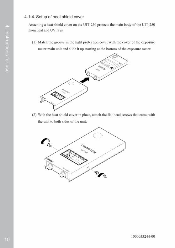
4-1-4. Setup of heat shield cover
Attaching a heat shield cover on the UIT-250 protects the main body of the UIT-250from heat and UV rays.
(1) Match the groove in the light protection cover with the cover of the exposure
meter main unit and slide it up starting at the bottom of the exposure meter.
UNIMETERUIT-250
ANA.OUT
Mode
Power
StartStop
H/M/L
mW/cm 2(°C)P.mW/cm 2(P.°C)mJ/cm 2
SIO I/F
ANA.OUT
UNIMETERUIT-250
(2) With the heat shield cover in place, attach the flat head screws that came with
the unit to both sides of the unit.
UNIMETER
UIT-250
ANA.O
UT
111000033244-00
4. Instructions for use
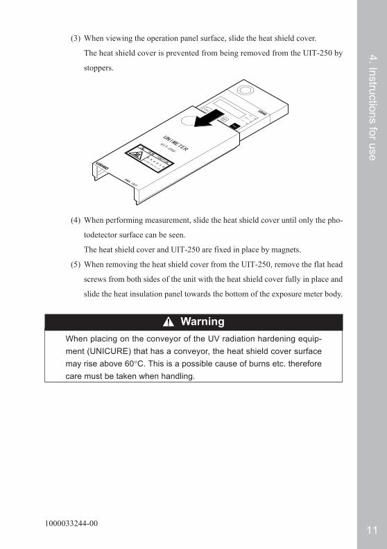
(3) When viewing the operation panel surface, slide the heat shield cover.
The heat shield cover is prevented from being removed from the UIT-250 by
stoppers.
(4) When performing measurement, slide the heat shield cover until only the pho-
todetector surface can be seen.
The heat shield cover and UIT-250 are fixed in place by magnets.
(5) When removing the heat shield cover from the UIT-250, remove the flat head
screws from both sides of the unit with the heat shield cover fully in place and
slide the heat insulation panel towards the bottom of the exposure meter body.
WarningWhen placing on the conveyor of the UV radiation hardening equip-ment (UNICURE) that has a conveyor, the heat shield cover surfacemay rise above 60°C. This is a possible cause of burns etc. thereforecare must be taken when handling.
121000033244-00
4. Instructions for use
4-1-5. Auto-power-off function
The UIT-250 has an auto-power-off function.The unit automatically turns off after 5 minutes elapses from when the operation switchis pushed.The auto-power-off function is enabled when we ship the unit.This function can be disabled using the following procedure.
Important1. Remove the batteries prior to performing the operation.2. Do not set a setting other than designated.
This can cause failure or malfunction.
(1) Stand the exposure meter up and remove the batteries.
- Reference "4-1-1. Insertion and replacement of batteries" for removal of bat-
teries.
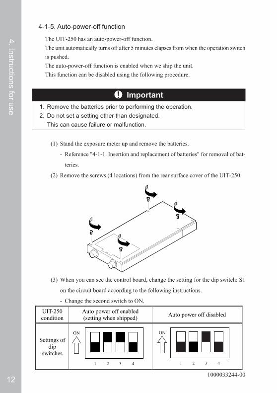
(2) Remove the screws (4 locations) from the rear surface cover of the UIT-250.
(3) When you can see the control board, change the setting for the dip switch: S1
on the circuit board according to the following instructions.
- Change the second switch to ON.
UIT-250 condition
Auto power off enabled (setting when shipped) Auto power off disabled
Settings of dip
switches

131000033244-00
4. Instructions for use
4-2. Measurement Method4-2-1. Toggling the rise and sample rate
The UIT-250 performs selection of sample rate simultaneous with turning the unit on.
(1) Selection of sample rate is performed when the unit is turned on.
• When selecting 32 samples/second
- Prevent light from reaching the photodetector surface and push the
switch.
- A sample rate of 32 samples/second is selected.
- is indicated on the display monitor.
• When selecting 16 samples/second
- Prevent light from reaching the photodetector surface and push the
switch while holding down the switch.
- A sample rate of 16 samples/second is selected.
- is indicated on the display monitor.
Important1. Connect either a photodetector or a temperature sensor prior to turn-
ing the unit on. If the photodetector or temperature sensor is connectedafter turning the unit on, an incorrect value will be displayed.
2. Prevent light from reaching the photodetector surface when turning theunit on.
(2) Numbers are shown on the display monitor and all indicators are blinking.
(3) Initialization finishes in roughly 5 seconds and real time irradiance measure-
ment mode is entered.
ImportantThe sample rate is only selected when the unit is turned on.When toggling of the sample rate is desired, first turn the unit off andthen turn it back on.
141000033244-00
4. Instructions for use
4-2-2. Turning unit off
(1) Push the switch for roughly 1 second.
- Numbers on the display monitor disappear.
- The power is turned off.
4-2-3. Real time irradiance (temperature) measurement
(1) When the UIT-250 is turned on, it enters H range real time irradiance measure-
ment mode.
- The real time irradiance indicator is blinking.
- The average value for 0.5 seconds is indicated on the display monitor.
- When a temperature sensor is connected, the thermocouple temperature is
indicated on the display panel.
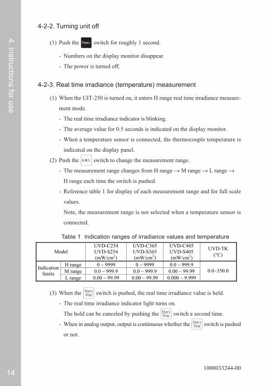
(2) Push the switch to change the measurement range.
- The measurement range changes from H range → M range → L range →
H range each time the switch is pushed.
- Reference table 1 for display of each measurement range and for full scale
values.
Note, the measurement range is not selected when a temperature sensor is
connected.
Table 1 Indication ranges of irradiance values and temperature
Model UVD-C254 UVD-S254 (mW/cm2)
UVD-C365 UVD-S365 (mW/cm2)
UVD-C405 UVD-S405 (mW/cm2)
UVD-TK (°C)
H range 0 ~ 9999 0 ~ 9999 0.0 ~ 999.9 M range 0.0 ~ 999.9 0.0 ~ 999.9 0.00 ~ 99.99 Indication
limits L range 0.00 ~ 99.99 0.00 ~ 99.99 0.000 ~ 9.999
0.0~350.0
(3) When the switch is pushed, the real time irradiance value is held.
- The real time irradiance indicator light turns on.
The hold can be canceled by pushing the switch a second time.
- When in analog output, output is continuous whether the switch is pushed
or not.

151000033244-00
4. Instructions for use
(4) If the irradiance measured exceeds the full scale irradiance value, it is regarded as
a scale over and the maximum value for the current measurement range is indi-
cated on the display monitor.
(Example: when measurement is made in H range using the UVD-C405
is indicated on the display monitor.)
If full scale irradiance is exceeded, raise the measurement range and perform
the measurement.
(5) If the measured temperature exceeds full scale temperature value it is regarded
as a scale over and is indicated on the display monitor.
When the measured temperature decreases to within the temperature range that
can be displayed, the temperature is again indicated.
4-2-4. Peak irradiance (temperature) measurement
(1) Turn on the UIT-250.
(2) Push the switch once.
- Unit enters peak irradiance measurement mode.
- The peak irradiance indicator is blinking.
(3) Press the switch to change measurement range.
- The measurement range changes from H range → M range → L range →
H range each time the switch is pushed.
- The peak irradiance value is reset when the measurement range is changed.
- Reference table 1 in "4-2-3 Real time irradiance (temperature) measurement"
for display and full scale for each measurement range.
(4) The peak irradiance value is reset when the switch is pushed.
The peak irradiance value is indicated on the display monitor until the
switch is pushed again.
(5) Peak temperature measurement is performed in this same manner.
However, the measurement range can not be selected.

161000033244-00
4. Instructions for use
4-2-5. Accumulated exposure amount measurement
(1) Turn on the UIT-250.
(2) Press the switch twice.
- The accumulated exposure amount measurement mode is entered.
- The accumulated exposure amount indicator is blinking. Accumulated expo-
sure amount measurement standby is entered.
(3) Press the switch to change the measurement range.
- The measurement range changes from H range → M range → L range →
H range each time the switch is pushed.
- When the measurement range is changed, the accumulated exposure amount
value is reset.
The measurement range can not be changed while measurement is being per-
formed.
- If the switch is pushed continuously when the measurement range is
being changed, the real time irradiance is indicated on the display monitor.
- Reference Table 2 below concerning the display and full scale accumulated
exposure amount value for each measurement range.
Table 2 Indication limits for accumulated exposure amount values and
temperature
Model UVD-C254 UVD-S254 (mJ/cm2)
UVD-C365 UVD-S365 (mJ/cm2)
UVD-C405 UVD-S405 (mJ/cm2)
UVD-TK (°C)
H range 0 ~ 99999 0 ~ 99999 0.0 ~ 9999.9 M range 0.0 ~ 9999.9 0.0 ~ 9999.9 0.00 ~ 999.99 Indication
limits L range 0.00 ~ 999.99 0.00 ~ 999.99 0.000 ~ 99.999
0.0 ~ 9999.9
(4) Push the switch.
- Accumulated measurement of exposure amount is started.
- The accumulated exposure amount indicator blinks.
- The measured time is a maximum of 2 minutes (32 samples/second) or
4 minutes (16 samples/second) for 3840 pieces of data.
(5) Press the switch to stop accumulated exposure amount measurement.
- The accumulated exposure amount value is indicated on the display monitor.
- The accumulated exposure amount indicator turns on.
(6) If the switch is pushed again, the accumulated exposure amount value is
reset and accumulation measurement of exposure amount is performed again.

171000033244-00
4. Instructions for use
4-3. Output of Measurement Results4-3-1. Analog output
In addition to indicating the irradiance value on the display monitor the UIT-250 alsooutputs the value as an analog voltage signal using the analog signal output terminal.An analog signal is output using the analog signal output terminal in real time for realtime irradiance measurement mode, peak irradiance measurement mode, accumulatedexposure amount measurement mode, and irradiance distribution measurement mode.A recorded analog signal is output when in irradiance distribution measurement mode.
(1) Connect the analog signal output cable that came with the unit to the analog
signal output terminal.
- Connect the orange and white wires of the analog signal output cable respec-
tively to the +, − terminals of the recorder device (oscilloscope, pen recorder
etc.).
Important1. The output impedance of the analog signal output is 1 kΩ. In order to
provide a correct measurement it is recommended that the input im-pedance of the recorder device be greater than 1 MΩ.
2. If the input impedance of the recorder device is low, the measuredvalue may be low.
(2) Press the switch.
- Output starts.
- The irradiance distribution is output in the range of 0 − 1 V of the analog
voltage signal. When irradiance is 0, the analog signal is 0 V. When the irra-
diance value is at its full scale value the analog signal outputs 1 V.
- The analog voltage signal for temperature distribution is output in the limits
of 0 − 1.75 V. When temperature is 0°C the voltage is 0V and when the
temperature is 200°C a 1 V signal is output.
181000033244-00
4. Instructions for use
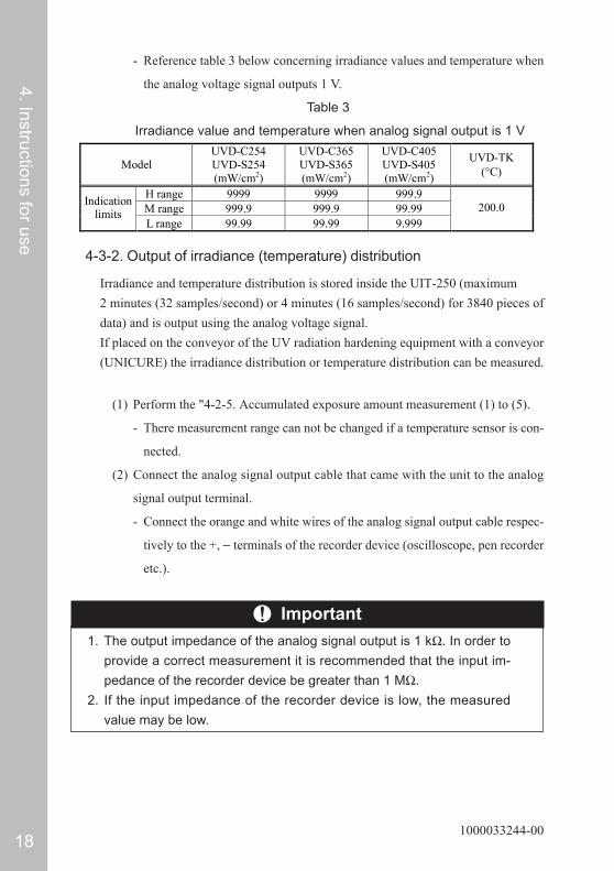
- Reference table 3 below concerning irradiance values and temperature when
the analog voltage signal outputs 1 V.
Table 3
Irradiance value and temperature when analog signal output is 1 V
Model UVD-C254 UVD-S254 (mW/cm2)
UVD-C365 UVD-S365 (mW/cm2)
UVD-C405 UVD-S405 (mW/cm2)
UVD-TK (°C)
H range 9999 9999 999.9 M range 999.9 999.9 99.99 Indication
limits L range 99.99 99.99 9.999
200.0
4-3-2. Output of irradiance (temperature) distribution
Irradiance and temperature distribution is stored inside the UIT-250 (maximum2 minutes (32 samples/second) or 4 minutes (16 samples/second) for 3840 pieces ofdata) and is output using the analog voltage signal.If placed on the conveyor of the UV radiation hardening equipment with a conveyor(UNICURE) the irradiance distribution or temperature distribution can be measured.
(1) Perform the "4-2-5. Accumulated exposure amount measurement (1) to (5).
- There measurement range can not be changed if a temperature sensor is con-
nected.
(2) Connect the analog signal output cable that came with the unit to the analog
signal output terminal.
- Connect the orange and white wires of the analog signal output cable respec-
tively to the +, − terminals of the recorder device (oscilloscope, pen recorder
etc.).
Important1. The output impedance of the analog signal output is 1 kΩ. In order to
provide a correct measurement it is recommended that the input im-pedance of the recorder device be greater than 1 MΩ.
2. If the input impedance of the recorder device is low, the measuredvalue may be low.

191000033244-00
4. Instructions for use
(3) Press the switch once.
- is indicated in display monitor.
- All indicators are turned off.
(4) When the switch is pushed, the irradiance distribution is output on the
analog voltage signal.
- is blinked on the display monitor.
- The irradiance distribution is output using the 0 − 1 V of the analog voltage
signal. When the irradiance value is 0 the analog signal is 0 V. When the
irradiance value is at full scale, the analog signal outputs 1 V.
- The temperature distribution is output in the range of the analog voltage sig-
nal of 0 − 1.75 V. When the temperature is 0°C, the analog signal output is
0 V. When the temperature is 200°C, the analog signal is 1 V.
- Reference "4-3-1. Analog output" for irradiance and temperatures when ana-
log voltage is 1 V.
(5) When the output of the analog voltage signal is complete, the peak irradiance
value or peak temperature is indicated on the display monitor.
- The irradiance distribution is output for 2 minutes for either sampling rate
(16 or 32 samples/minute).
The distribution output is coarser for a sample rate of 16 samples/second than
it is for 32 samples/second.
(6) If you would like to know the accumulated exposure amount for the irradiance
distribution, push the switch 3 times.
- Accumulated measurement mode is entered.
- The accumulated exposure amount value is indicated on the display monitor.
(7) If the switch is pressed during output of the analog voltage signal the
output is forcefully stopped.
- The peak irradiance or peak temperature value is indicated on the display
monitor.
201000033244-00
4. Instructions for use
4-4. Serial Communication FunctionThe UIT-250 has a serial communication function and the serial communication cablethat comes with the unit can be connected to the serial port such as the PC-AT port ofa personal computer (hereafter: PC).Through connecting the UIT-250 to a PC, the following can be performed.
- Reading of irradiance distribution data
- Confirmation of samples/second
- Selection of measurement range
- Measurement of irradiance (temperature)
The specification for the communication function of the UIT-250 is as described be-low:
Communication specification: Half duplex
Synchronization method: Start/stop synchronization (asynchronous)
Baud rate: 4800 bps (fixed)
Transmission code: ASCII
Data length: 8 bit (fixed)
Stop bit: 1
Parity: None
Delimiter: CR
This function is used mutually exclusive with the analog output of the distributionmeasurement function of irradiance (temperature). Analog output can not be performedwhile the communication function is operating. Note, PC communication softwaredoes not come with this unit. Please prepare separately.In this document, unless otherwise indicated CR designates "Hex 0d" in the ASCIIcode.

211000033244-00
4. Instructions for use
The connection between the UIT-250 and a PC confirmed has the followingconditions for the communication environment.
PC: PC-AT (has not been confirmed on Macintosh)
OS: Windows XP (SP1), Windows 2000 (SP4)
Communication software: HyperTerminal
* Operation with an expansion serial port based on USB using the above
OS has been confirmed as well.
* Prior to use, check the communication specifications of the above devices.
Use the serial communication cable that came with the unit to connect the UIT-250and PC in the following manner.
ImportantDo not use a cable other than the serial communication cable that camewith the unit.This is a cause of error and/or failure.
Serial communication configuration diagram
221000033244-00
4. Instructions for use
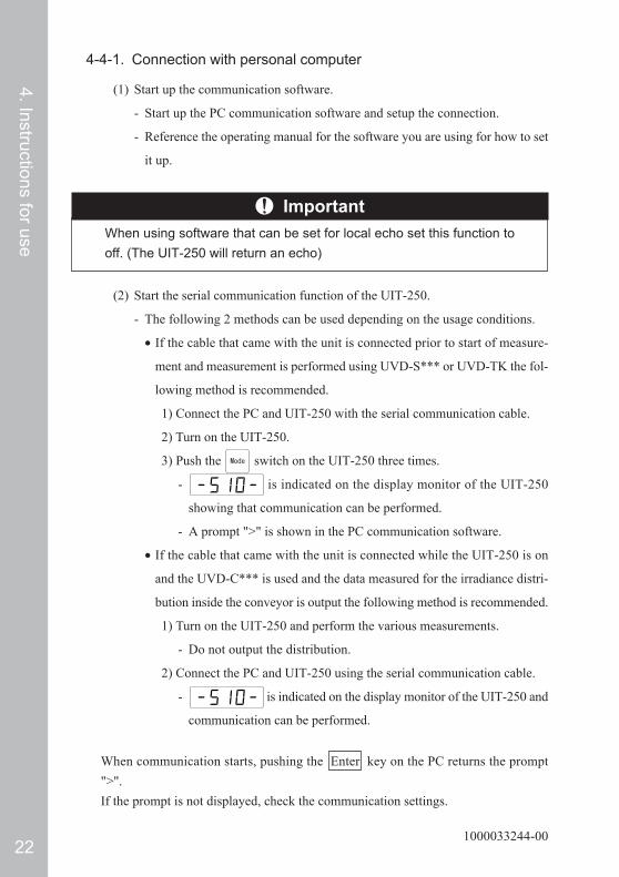
4-4-1. Connection with personal computer
(1) Start up the communication software.
- Start up the PC communication software and setup the connection.
- Reference the operating manual for the software you are using for how to set
it up.
ImportantWhen using software that can be set for local echo set this function tooff. (The UIT-250 will return an echo)
(2) Start the serial communication function of the UIT-250.
- The following 2 methods can be used depending on the usage conditions.
• If the cable that came with the unit is connected prior to start of measure-
ment and measurement is performed using UVD-S*** or UVD-TK the fol-
lowing method is recommended.
1) Connect the PC and UIT-250 with the serial communication cable.
2) Turn on the UIT-250.
3) Push the switch on the UIT-250 three times.
- is indicated on the display monitor of the UIT-250
showing that communication can be performed.
- A prompt ">" is shown in the PC communication software.
• If the cable that came with the unit is connected while the UIT-250 is on
and the UVD-C*** is used and the data measured for the irradiance distri-
bution inside the conveyor is output the following method is recommended.
1) Turn on the UIT-250 and perform the various measurements.
- Do not output the distribution.
2) Connect the PC and UIT-250 using the serial communication cable.
- is indicated on the display monitor of the UIT-250 and
communication can be performed.
When communication starts, pushing the Enter key on the PC returns the prompt">".If the prompt is not displayed, check the communication settings.

231000033244-00
4. Instructions for use
4-4-2. Commands
When a command (1 character) and the Enter key is input from the PC, the UIT-250executes the command and returns a response to the PC.
- While the command is being executed, is indicated on the dis-
play monitor of the UIT-250.
- Does not distinguish between capital letters and small letters.
- If a command is mistakenly input, an error message is returned.
- If a mistake is made when writing a command press the BackSpace key and
correct it.
- The commands, their functions, and response for the UIT-250 are described
below.
>m Enter ← Execution of irradiance measurement command Current Irradiance [mW/cm²] = 0.0 CR LR ← Direct display of irradiance after measurement of
irradiance >r Enter ← Execution of check of the current sampling rate Sample rate: H (31.25 msec/data) CR LF ← Direct display of irradiance after measurement of
irradiance > Enter ← Press ENTER without entering a command > ← Prompt ">" is returned >k Enter ← Enter an incorrect command Error: Illegal command!! Please input correct command. (HELP?) CR LF ← Returns an error message.
Command Function and response
R Displays the current sampling rate. *1
G Indicates the current range that has been set.
Q Sets the measurement range to "H range". *2
W Sets the measurement range to "M range". *2
E Sets the measurement range to "L range". *2
M Measures the current irradiance (temperature) and displays the value.
S Outputs the stored irradiance distribution.
V Indicates the version of the firmware.
? Indicates the commands that can be used. (help) *1 The sampling rate can not be changed.*2 Does not function when a UVD-TK is implemented.Communication example (explanation given to the right of the ←. Output is not actu-ally performed.)

241000033244-00
4. Instructions for use
4-4-3. Output of irradiance distribution
(1) Performs measurement of accumulated exposure amount.
- Reference "4-2-5. Accumulated exposure amount measurement" for the mea-
surement method of the accumulated amount of exposure.
(2) Connect the PC and UIT-250 using a cable.
- Reference "4-4-1. Connection with a personal computer" for how to connect.
(3) Enter an S at the PC and push ENTER .
- The output of measurement data for measurement of accumulated exposure
amount measurement is started.
- While the command is being executed, blinks on the display
monitor.
- If the ESC key on the PC is entered, the output is caused to stop.
- If this is executed in a condition where accumulated exposure amount mea-
surement has not been performed a warning is returned.
CautionDo not remove the cable while communication operation is being ex-ecuted. This can cause errors and/or a failure.
The format of the output data is shown by the following.The "*" in the table is for information dependent on conditions when measurement ismade and "D" is the number of number of pieces of data (maximum 3840).Output order Content format
1 Sample rate for accumulated exposure amount measurement Output type: sample rate: ∗ (∗∗.∗∗ msec./data) CR, LF
2 Range for accumulated exposure amount measurement Output type: Range: ∗ CR LF ♦ When UVD-TK is implemented, only CR and LF are output.
3 • • • • • •
D+2
Data number, irradiance (temperature) Output type: (data number), (irradiance (temperature)) CR, LF ♦1 The placement of the decimal of the irradiance
(temperature) is determined by the photodetector attached and by the range at time of measurement.
♦2 The "," between the data number and irradiance (temperature) is "Hex 2c".
D+3 Peak value in distribution of irradiance Output type: Peak irradiance [mW/cm2] = (peak irradiance)
[Peak temperature [degree]] = (peak temperature)
D+4 DATA output finished message for irradiance distribution. : DATA output finished!

251000033244-00
4. Instructions for use
Communication example (explanation given to the right of the ← arrow. Output is notactually performed.)
>s Enter ← Execution of output command of irradiance distribution prior to implementing accumulated exposure amount measurement
Notice: No data exists CR LF ← Indication of warning message >s Enter ← Execution of irradiance distribution output
command after implementing accumulated exposure amount measurement
Sample rate: H (31.25 msec/data) CR LF ← Indicates sample rate for accumulated exposure amount measurement
Gain: M CR LF ← Indicates range for accumulated exposure amount measurement
1, 100.0 CR LF ← Indicates irradiance value after measurement of irradiance
2, 100.0 CR LF 3, 100.1 CR LF · · 3839, 99.9 CR LF 3840, 100.0 CR LF Peak Irradiance [mW/cm²] = 100.1 CR LF ← Indicates peak irradiance Data output finished! CR LF ← Message that output of irradiance distribution is
finished > ← After finishing execution of command, it waits
for the next command.

261000033244-00
4. Instructions for use
5. Error DisplayThe UIT-250 indicates the following four kinds of errors on the display monitor de-pending on its condition:
Error Display Error Contents Error Cause Measure
When the temperature is measured by the temperature sensor, the measured value has exceeded the temperature measured range (0 to 350°C).
A high temperature that exceeds the measure temperature range.
Indicate the temperature within the temperature measured range.
Overheat error (Abnormal temperature error).
The UIT-250 is used at a high temperature that exceeds the temperature measured range.
Turn off the power and cool the UIT-250 naturally.
Abnormal battery voltage error.
The battery level has run low.
Turn off the power, and replace the battery cells with new ones.
System down error. The CPU may have
failed. Turn off the power, and turn it on again.
5. Error Display
271000033244-00
4. Instructions for use6. Troubleshooting
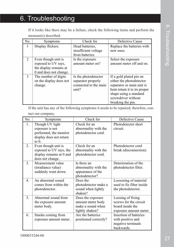
6. TroubleshootingIf it looks like there may be a failure, check the following items and perform themeasure(s) described.
No. Symptoms Check for Defective Cause 1 Display flickers. Dead batteries,
insufficient voltage from batteries.
Replace the batteries with new ones.
2 Even though unit is exposed to UV rays, the display remains at 0 and does not change.
Is the exposure amount meter on?
Select the exposure amount meter off and on.
3 The number of digits on the display does not change.
Is the photodetector separator properly connected to the main unit?
If a gold plated pin on either the photodetector separator or main unit is bent return it to its proper shape using a standard screwdriver without breaking the pin.
If the unit has any of the following symptoms it needs to be repaired; therefore, con-tact our company.
No. Symptoms Check for Defective Cause 1. Though UV light
exposure is not performed, the monitor display does not return to 0.
Check for an abnormality with the photodetector cord.
Photodetector short circuit.
2. Even though unit is exposed to UV rays, the display remains at 0 and does not change.
Check for an abnormality with the photodetector cord.
Photodetector cord break (disconnection).
3. Measurement value (irradiance value) suddenly went down.
Is there an abnormality with the appearance of the photodetector?
Deterioration of the photodetector filter.
4. An abnormal sound comes from within the photodetector.
Does the photodetector make a sound when lightly shaken?
Loosening of material used to fix filter inside the photodetector.
5. Abnormal sound from the exposure amount meter body.
Does the exposure amount meter body make a sound when lightly shaken?
Loosing of fixing screws for the circuit board inside the exposure amount meter.
6. Smoke coming from exposure amount meter.
Are the batteries positioned correctly?
Insertion of batteries with positive and negative terminals backwards.

281000033244-00
4. Instructions for use
7. Warranty and Repair
7-1. WarrantyThis measuring instrument is delivered after USHIO has thoroughly inspected theinstrument and check that its performance satisfies the specifications. If this instru-ment fails due to its material or poor workmanship, or if it has failed due to an acci-dent during transportation, please contact USHIO. The warranty term of this instru-ment shall be one year after its delivery or three months after repair. If this instrumentfails under normal operating conditions within this warranty term, USHIO will repairor replace the instrument free of charge.However, this instrument is not covered by warranty I fit is used in a wrong manner (amanner not described in the operation manual) or in the careless manner, if it is modi-fied, or if it has failed due to a natural disaster, etc.
7-2. RepairIf this instrument is judged as to have failed, or if you are unclear on any point, pleaseinform USHIO of the model manufacturing number and symptom in details. How-ever, please understand that USHIO is not obligated to repair the instrument if it ismodified.
7-3. Calibration (Main Unit and Photodetector Unit)In order to ensure measurement accuracy, it is recommended that this instrument becalibrated once every 6 months.If you have any questions concerning repair or calibration please contact your repre-sentative salesperson.
7. Warranty and R
epair

291000033244-00
4. Instructions for use
8. SpecificationsUIT-250 Unit Specifications
Display An LCD is used to indicate the irradiance in 4 digits and accumulated exposure amount in 5 digits.
Functions Real-time irradiance/peak irradiance/accumulated exposure amount/irradiance distribution/temperature measurement mode, three selectable measurement ranges, and an auto-power-off function (5 minutes).
Irradiance distribution output
Output of analog voltage 0 to 1 V, maximum recording time of 2 or 4 minutes (a recorder is connected).
Sampling rate 16 or 32 samples/second.
Communication specification
Communication specification :Half duplex Synchronization method: Start/stop synchronization (asynchronous) Baud rate: 4800 bps (fixed) Transmission code: ASCII Data length: 8 bit (fixed) Stop bit: 1 Parity: None Delimiter: CR
Power 3 AAA batteries Dimensions (mm) 75 (W) × 160 (D) × 15 (H) Weight (g) Under 250 g (only for main unit and does not include batteries)
Mode PowerStart
StopH/M/L
mW/cm2
( )
P.mW/cm2
(P. )
mJ/cm2
UNIMETER
UIT-250
SIO I/F ANA.OUT
UNIMETER
UIT-250
ANA.OUT
160
75 15
171
79.4
18.8
21.5
19
303015 29
1000
308.
2
1000
35
Separate-type photodetectorIntegrated-type photodetector Temperature sensor
UIT-250 unit Heat shield cover
Units : mm
8. Specifications

301000033244-00
4. Instructions for use
Model UVD-C254 UVD-C365 UVD-C405
Sensitivity wavelength region (nm) 220 ~ 310 310 ~ 390 320 ~ 470
Wavelength for calibrating absolute
value (nm) 254 365 405
Photodetector diameter (mm) φ 10 φ 10 φ 10
Non-linearity Within ± 1% Within ± 1% Within ± 1% Temperature measured
range (°C) 0 ~ 50 0 ~ 50 0 ~ 50
H range 0 ~ 9999 0 ~ 9999 0.0 ~ 999.9
M range 0.0 ~ 999.9 0.0 ~ 999.9 0.00 ~ 99.99
Irradiance measured
ranges (mW/cm²) L range 0.00 ~ 99.99 0.00 ~ 99.99 0.000 ~ 9.999
H range 0 ~ 99999 0 ~ 99999 0.0 ~ 9999.9
M range 0.0 ~ 9999.9 0.0 ~ 9999.9 0.00 ~ 999.99
Accumulated light amount measurement
range (mJ/cm²) L range 0.00 ~ 999.99 0.00 ~ 999.99 0.000 ~ 99.999
Spectroscopic sensitivity characteristics
Model UVD-S254 UVD-S365 UVD-S405
Sensitivity wavelength region (nm) 220 ~ 310 310 ~ 390 320 ~ 470
Wavelength for calibrating absolute
value (nm) 254 365 405
Photodetector diameter (mm) φ 3 φ 1 φ 1
Non-linearity Within ± 1% Within ± 1% Within ± 1% Temperature measured
range (°C) 0 ~ 50 0 ~ 50 0 ~ 50
H range 0 ~ 9999 0 ~ 9999 0.0 ~ 999.9
M range 0.0 ~ 999.9 0.0 ~ 999.9 0.00 ~ 99.99
Irradiance measured
ranges (mW/cm²) L range 0.00 ~ 99.99 0.00 ~ 99.99 0.000 ~ 9.999
H range 0 ~ 99999 0 ~ 99999 0.0 ~ 9999.9
M range 0.0 ~ 9999.9 0.0 ~ 9999.9 0.00 ~ 999.99
Accumulated light amount measurement
range (mJ/cm²) L range 0.00 ~ 999.99 0.00 ~ 999.99 0.000 ~ 99.999
Spectroscopic sensitivity characteristics
Integrated-type photodetector Specifications
Separate-type photodetector Specifications
10.90.80.70.60.50.40.30.20.1
0200 250 300 350
Wavelength(nm)
Rel
ativ
e sp
ectr
osco
pic
sens
itivi
ty
10.90.80.70.60.50.40.30.20.1
0300 350 400
Wavelength(nm)
Rel
ativ
e sp
ectr
osco
pic
sens
itivi
ty
10.90.80.70.60.50.40.30.20.1
0300 350 400 500450
Wavelength(nm)
Rel
ativ
e sp
ectr
osco
pic
sens
itivi
ty
10.90.80.70.60.50.40.30.20.1
0200 250 300 350
Wavelength(nm)
Rel
ativ
e sp
ectr
osco
pic
sens
itivi
ty
10.90.80.70.60.50.40.30.20.1
0300 350 400
Wavelength(nm)
Rel
ativ
e sp
ectr
osco
pic
sens
itivi
ty
10.90.80.70.60.50.40.30.20.1
0300 350 400 500450
Wavelength(nm)
Rel
ativ
e sp
ectr
osco
pic
sens
itivi
ty
8. Specifications

311000033244-00
4. Instructions for use
Model UTD-TK Temperature measured range (°C) 0 ~ 350
Thermocouple line Chromael/Almel wire
Temperature Sensor Specifications
* The specification and appearance of the product noted here may be changed,
such as due to a revision, without notification.

321000033244-00
4. Instructions for use
9. DisclaimerIn the following circumstances, USHIO does not accept responsibility under any con-dition.
- Failure caused by usage or handling in conditions or environments other than
as described in the operating manual, catalog, or technical materials.
- Repair or modification is performed by other than USHIO.
- Failures where cause is other than product from USHIO such as software de-
sign content or the customer's equipment etc.
- Failure caused by external factors for which USHIO is not responsible such as
natural disasters or other acts of God.
- Secondary failures (such as equipment damage, physical loss, loss of business
profit etc.) caused by use or failure of this unit.
- Failure that could not be predicted using the level of technology available when
unit was shipped.
9. Exclusions


USHIO INC.URL http://www.ushio.co.jp