USG Cavity Shaft Wall System - Product Data - buildsite.com · – UL Classified as to fire...
44
Life safety assurance for modern building designs Shaft Wall Systems
Transcript of USG Cavity Shaft Wall System - Product Data - buildsite.com · – UL Classified as to fire...
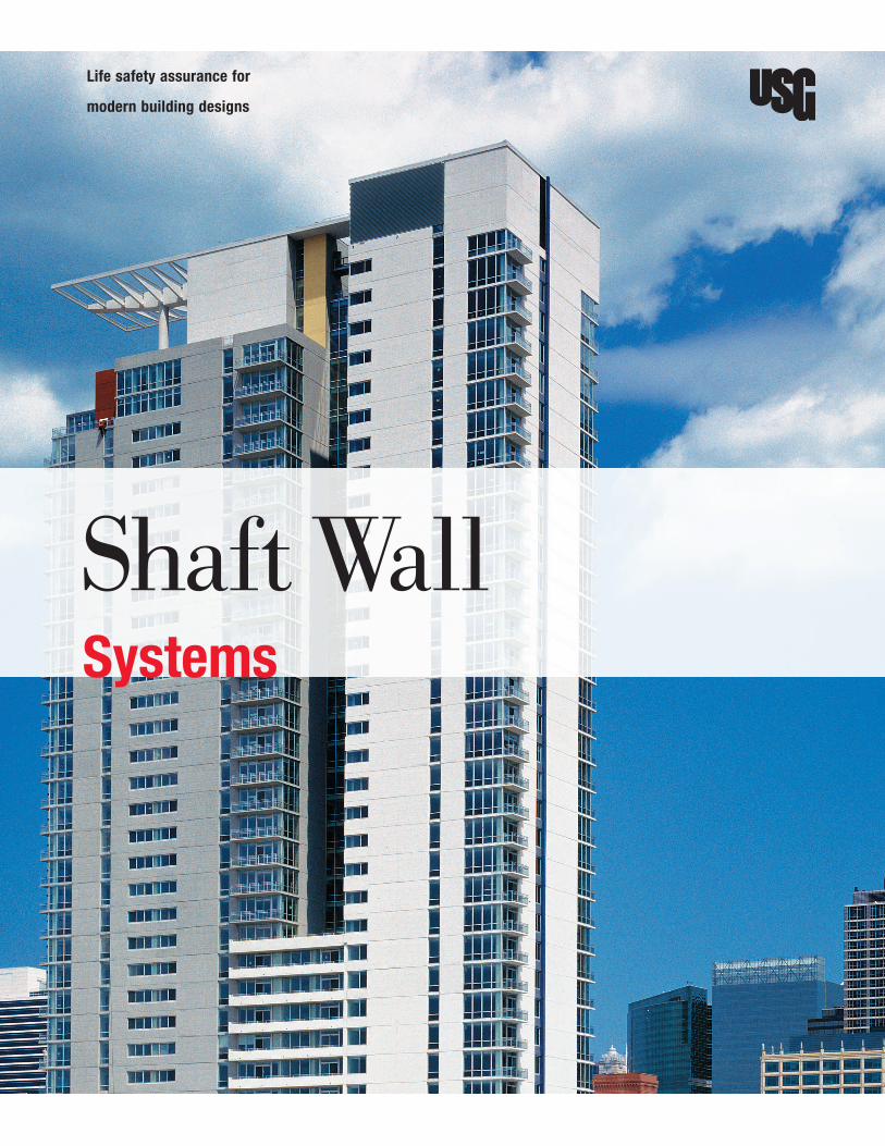
Life safety assurance for
modern building designs
Shaft Wall Systems

Walls that enclose elevator shafts, stairwells and other vertical shafts are
the lifeline of a building. Should a fire occur, firefighters control the use
of elevators, leaving stairwells as the only means for occupant egress or
rescue within the building. Since these walls are an important part of
the building, they must have the strength to withstand lateral loads and
provide needed fire protection.
High-Performance Shaft Walls
3 USG Shaft Wall Systems
User’s Guide
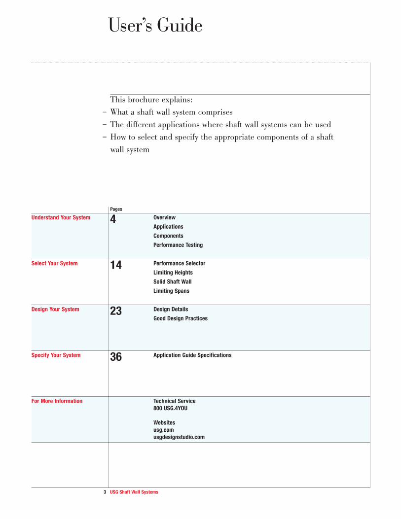
This brochure explains:
– What a shaft wall system comprises
– The different applications where shaft wall systems can be used
– How to select and specify the appropriate components of a shaft
wall system
Pages
Understand Your System 4 Overview
Applications
Components
Performance Testing
Select Your System 14 Performance Selector
Limiting Heights
Solid Shaft Wall
Limiting Spans
Design Your System 23 Design Details
Good Design Practices
Specify Your System 36 Application Guide Specifications
For More Information Technical Service
800 USG.4YOU
Websites
usg.com
usgdesignstudio.com

4 USG Shaft Wall Systems
Overview
USG shaft wall systems are non-loadbearing gypsum wall partition
assemblies constructed from outside the shaft at each floor. Shafts are
enclosed early in construction, and the walls are finished later, along
with interior partitions. Installation is quick and easy, using components
and application procedures familiar to drywall contractors. This system
installs faster than other multilayer gypsum panel systems because it is
installed from one side, leaving the shaft free of scaffolding. The assemblies
are constructed of gypsum liner panels friction-fitted into C-H studs in a
progressive manner, with gypsum panels, gypsum fiber panels or cement
board applied to the face.
Typical Shaft
Wall Assembly
Utility chase
USG C-H stud
USG C-H stud
USG J-runner
Two USG Jamb Struts
USG Sheetrock® Brand Gypsum Panels
USG Sheetrock® Brand Gypsum Panels
Elevator car
Elevator shaft
Elevator shaft door frame
1" USG Sheetrock® Brand Gypsum Liner Panels
1" USG Sheetrock® Brand Gypsum Liner Panels
1" USG Sheetrock® Brand Mold Tough® Liner Panels
1" USG Sheetrock® Brand Glass-Mat Liner Panels
5 USG Shaft Wall Systems
Applications
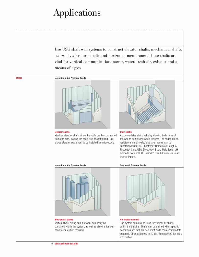
Use USG shaft wall systems to construct elevator shafts, mechanical shafts,
stairwells, air return shafts and horizontal membranes. These shafts are
vital for vertical communication, power, water, fresh air, exhaust and a
means of egres.
Walls Intermittent Air Pressure Loads
Elevator shafts Stair shafts
Ideal for elevator shafts since the walls can be constructed Accommodates stair shafts by allowing both sides of
from one side, leaving the shaft free of scaffolding. This the wall to be finished when required. For added abuse
allows elevator equipment to be installed simultaneously. resistance in stairwells, face layer panels can be
substituted with USG Sheetrock® Brand Mold Tough AR
Firecode® Core, USG Sheetrock® Brand Mold Tough VHI
Firecode Core or USG Fiberock® Brand Abuse-Resistant
Interior Panels.
Intermittent Air Pressure Loads Sustained Pressure Loads
Mechanical shafts Air shafts (unlined)
Vertical HVAC piping and ductwork can easily be The system can also be used for vertical air shafts
contained within the system, as well as allowing for wall within the building. Shafts can be unlined when specific
penetrations when required. conditions are met. Unlined shaft walls can accommodate
sustained air pressure up to 10 psf. See page 20 for more
information.
6 USG Shaft Wall Systems
Applications
Walls Solid Shafts Horizontal Stud Shafts
Ceilings Shaft Wall Ceiling Membrane
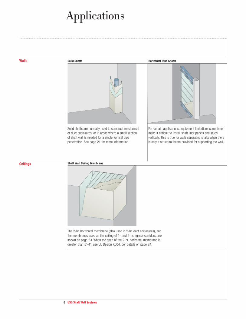
Solid shafts are normally used to construct mechanical
or duct enclosures, or in areas where a small section
of shaft wall is needed for a single vertical pipe
penetration. See page 21 for more information.
For certain applications, equipment limitations sometimes
make it difficult to install shaft liner panels and studs
vertically. This is true for walls separating shafts when there
is only a structural beam provided for supporting the wall.
The 2-hr. horizontal membrane (also used in 2-hr. duct enclosures), and
the membranes used as the ceiling of 1- and 2-hr. egress corridors, are
shown on page 23. When the span of the 2-hr. horizontal membrane is
greater than 5'-4", use UL Design K504, per details on page 24.

7 USG Shaft Wall Systems
Components
USG shaft wall systems have been comprehensively tested for fire
resistance ratings only when all of the system components are used
together. Substitutions of any of the components are not recommended
and are not supported by USG. Refer to the appropriate product
material safety data sheet for complete health and safety information.
Gypsum Liner Panels USG Sheetrock® Brand Gypsum Liner Panels
– High-performance panel has a noncombustible core encased in a water-resistant 100% recycled green
face and back paper
– Underwriters Laboratories (UL)/Underwriters Laboratories Canada (ULC) Classified for fire resistance
– Panel is 1" thick and 24" wide with beveled edges
– Refer to product submittal sheet WB2278 for more information
USG Sheetrock® Brand Mold Tough Gypsum Liner Panels
– High-performance panel has a noncombustible and moisture- and mold-resistant gypsum core enclosed in a
moisture- and mold-resistant, 100% recycled blue face and back paper
– UL/ULC Classified as to fire resistance
– Panel is 1" thick and 24" wide with beveled edges
– Refer to product submittal sheet WB2389 for more information
USG Sheetrock® Brand Glass-Mat Liner Panels
– High-performance panel has a noncombustible and moisture- and mold-resistant gypsum core enclosed in
a moisture- and mold-resistant glass mat on both sides
– Can be left exposed for up to 12 months
– UL/ULC classified as to fire resistance
– Panel is 1" thick and 24" wide with beveled edges
– Refer to product submittal sheet WB2483 for more information
Gypsum Panels USG Sheetrock® Brand Firecode Core Gypsum Panels
and Cement Board – All of the advantages of regular panel with additional resistance to fire
– Available in 5/8" thickness, 4' width
– Refer to product submittal sheet WB1473 for more information
USG Sheetrock® Brand UltraLight Panels Firecode X Gypsum Panels
– All of the advantages of USG Sheetrock® Brand Firecode Core (Type X) Gypsum Panels
– 15% less weight makes it easier to transport, handle and install
– Available in 5/8" thickness, 4' width
– Refer to product submittal sheet WB2598 for more information
USG Sheetrock® Brand Firecode C Core Gypsum Panels
– Provide improved fire resistance over standard Firecode panels because of additives that enhance integrity of
the core under fire exposure
– Available in 5/8" and 1/2" thicknesses, 4' width
– Refer to product submittal sheet WB1473 for more information

8 USG Shaft Wall Systems
ComponentsComponents
USG Sheetrock® Brand Mold Tough Firecode Core Gypsum Panels
– Panel has a noncombustible, moisture- and mold-resistant gypsum core encased in a moisture- and mold-resistant,
100% recycled green face and brown back paper
– Tapered long edges for easy finishing
– Available in 5/8" thickness, 4' width
– 5/8" panel is UL Classified for fire resistance
– Refer to product submittal sheet WB2390 for more information
USG Sheetrock® Brand Mold Tough VHI Firecode Core Gypsum Panels
– Panel has a noncombustible, moisture- and mold-resistant gypsum core encased in a moisture- and mold-resistant,
100% recycled green face and brown back paper
– Tapered long edges for easy finishing
– Available in 5/8" thickness, 4' width
– 5/8" panel is UL Classified for fire resistance
– Core is reinforced with a high-strength mesh for heavy-duty impact-resistance
– Meet Level 3 performance per ASTM C1629, soft- and hard-body impact resistance
– Refer to product submittal sheet WB2529 for more information
USG Sheetrock® Brand Mold Tough AR Firecode Core Gypsum Panels
– Panel has a noncombustible, moisture- and mold-resistant gypsum core encased in a moisture- and mold-resistant,
100% recycled green face and brown back paper
– Tapered long edges for easy finishing
– Available in 5/8" thickness, 4' width
– 5/8" panel is UL Classified for fire resistance
– Manufactured for greater abuse resistance than standard 5/8" gypsum panels
– Meet Level 2 performance per ASTM C1629, soft- and hard-body impact resistance
– Refer to product submittal sheet WB2391 for more information
USG Sheetrock® Brand Glass-Mat Panels Mold Tough Firecode X
– Panel has a noncombustible, moisture- and mold-resistant gypsum core encased in a moisture- and mold-resistant, fiberglass mat
– Tapered long edges for easy finishing
– Available in 5/8" thickness, 4' width
– 5/8" panel is UL Classified for fire resistance
– Suitable for use in pre dry-in (aka “pre-rock”) and similar applications of wallboard before the building
envelop is fully enclosed
– Can be exposed to weather up to 12 months
– Refer to product submittal sheet WB2560 for more information
USG Sheetrock® Brand Glass-Mat Panels Mold Tough AR
– Panel has a noncombustible, moisture- and mold-resistant gypsum core encased in a moisture- and mold-resistant,
fiberglass mat
– Provide greater abuse resistance compared to standard drywall
– Resist surface abrasion, indentation and soft-body impact
– Suitable for use in pre dry-in (aka “pre-rock”) and similar applications of wallboard before the building envelope is fully enclosed
– Available in 5/8" thickness, 4' width
– Can be exposed to weather up to 12 months
– UL Classified as to fire resistance, surface-burning characteristics and noncombustibility
– Refer to product submittal sheet WB2750 for more information
9 USG Shaft Wall Systems
USG Sheetrock® Brand Glass-Mat Panels Mold Tough VHI
– Panel has a noncombustible, moisture- and mold-resistant gypsum core encased in a moisture- and mold-resistant,
fiberglass mat
– Provide superior impact resistance and are an upgrade to abuse-resistant panels
– Meet ASTM C1629 Level 3 (highest) for hard- and soft-body impact
– Suitable for use in pre dry-in (aka “pre-rock”) and similar applications of wallboard before the building envelope is fully enclosed
– Available in 5/8" thickness, 4' width
– Can be exposed to weather up to 12 months
– UL Classified as to fire resistance, surface-burning characteristics and noncombustibility
– Refer to product submittal sheet WB2749 for more information
USG Sheetrock® Brand Ultracode® Core Gypsum Panels
– 3/4" thick panel can achieve a two-hour fire rating with single-layer construction when used with mineral wool insulation
in steel framed walls
– Available in 4' width
– Refer to product submittal sheet WB2167 for more information
USG Sheetrock® Brand Mold Tough Ultracode Core Gypsum Panels
– 3/4" thick panel can achieve a two-hour fire rating with single-layer construction when used with mineral wool insulation
in steel framed walls
– Panel has a noncombustible moisture- and mold-resistant gypsum core encased in moisture- and mold-
resistant green face and brown back paper
– UL Classified as to fire resistance, surface-burning characteristics and noncombustibility
– Refer to product submittal sheet WB2388 for more information
USG Durock® Brand Cement Board
– Water-durable, mold-resistant substrate for high-moisture areas
– Refer to product submittal sheet CB399 for more information
USG Fiberock® Brand Abuse-Resistant Interior Panels
– Resist denting, breaking and puncturing, even in high-traffic areas
– Excellent fire resistance
– Made from 95% recycled materials
– Refer to product submittal sheet F102 for more information
USG Fiberock® Brand Aqua-Tough™ Interior Panels
– Used only for wall designs
– Increased resistance to abrasion, indentation and penetration
– Made from 95% recycled materials
– Refer to product submittal sheet F134 for more information
USG Imperial® Brand Firecode Core and Firecode C Core Gypsum Base
– Large size, rigid base for fire-rated gypsum veneer plaster systems
– Designed for direct or resilient attachment to wood or steel framing
– Multilayered laminated face paper to control water absorption and resist sag
– Refer to product submittal sheet P790 for more information
Components
10 USG Shaft Wall Systems
21/2", 4", 6"
1"
2"
3/4"1"
6"
1"
3/8"
1"
21/2", 4", 6" 3"
1"
7/32"
13/8"
21/2", 4", 6"
11/2"
10 USG Shaft Wall Systems
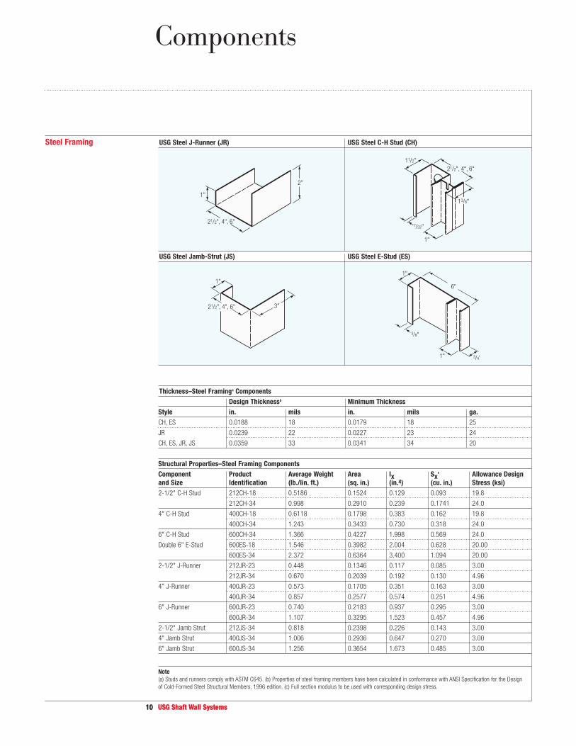
Steel Framing USG Steel J-Runner (JR) USG Steel C-H Stud (CH)
USG Steel Jamb-Strut (JS) USG Steel E-Stud (ES)
Thickness–Steel Framinga Components
Design Thicknessb Minimum Thickness
Style in. mils in. mils ga.
CH, ES 0.0188 18 0.0179 18 25
JR 0.0239 22 0.0227 23 24
CH, ES, JR, JS 0.0359 33 0.0341 34 20
Structural Properties–Steel Framing Components
Component Product Average Weight Area Ix Sxc Allowance Design
and Size Identification (lb./lin. ft.) (sq. in.) (in.4) (cu. in.) Stress (ksi)
2-1/2" C-H Stud 212CH-18 0.5186 0.1524 0.129 0.093 19.8
212CH-34 0.998 0.2910 0.239 0.1741 24.0
4" C-H Stud 400CH-18 0.6118 0.1798 0.383 0.162 19.8
400CH-34 1.243 0.3433 0.730 0.318 24.0
6" C-H Stud 600CH-34 1.366 0.4227 1.998 0.569 24.0
Double 6" E-Stud 600ES-18 1.546 0.3982 2.004 0.628 20.00
600ES-34 2.372 0.6364 3.400 1.094 20.00
2-1/2" J-Runner 212JR-23 0.448 0.1346 0.117 0.085 3.00
212JR-34 0.670 0.2039 0.192 0.130 4.96
4" J-Runner 400JR-23 0.573 0.1705 0.351 0.163 3.00
400JR-34 0.857 0.2577 0.574 0.251 4.96
6" J-Runner 600JR-23 0.740 0.2183 0.937 0.295 3.00
600JR-34 1.107 0.3295 1.523 0.457 4.96
2-1/2" Jamb Strut 212JS-34 0.818 0.2398 0.226 0.143 3.00
4" Jamb Strut 400JS-34 1.006 0.2936 0.647 0.270 3.00
6" Jamb Strut 600JS-34 1.256 0.3654 1.673 0.485 3.00
Note
(a) Studs and runners comply with ASTM C645. (b) Properties of steel framing members have been calculated in conformance with ANSI Specification for the Design
of Cold-Formed Steel Structural Members, 1996 edition. (c) Full section modulus to be used with corresponding design stress.
Components
11 USG Shaft Wall Systems
Components
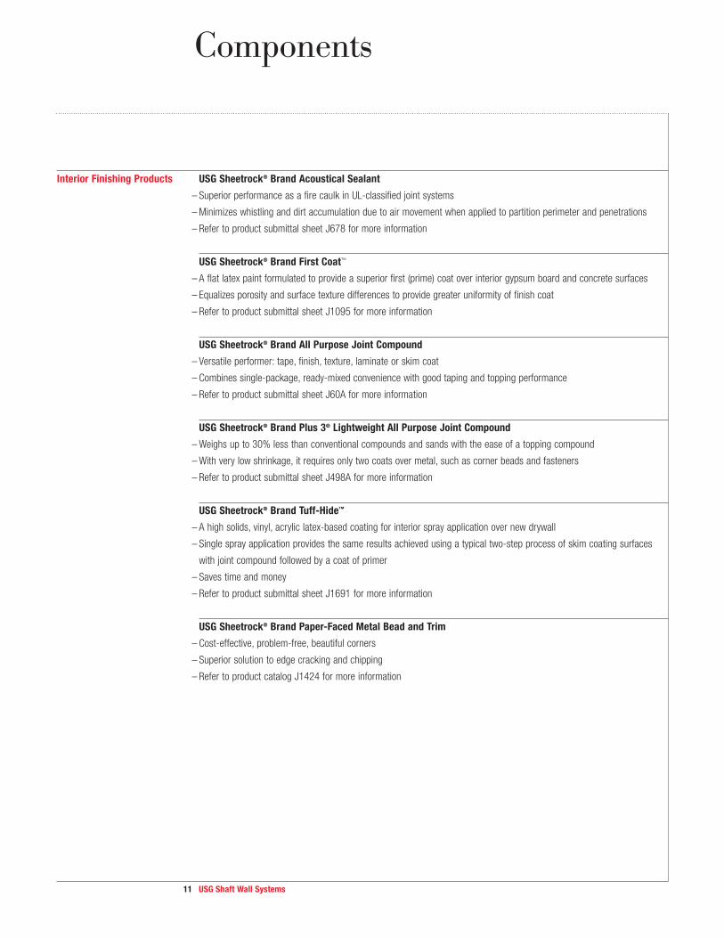
Interior Finishing Products USG Sheetrock® Brand Acoustical Sealant
– Superior performance as a fire caulk in UL-classified joint systems
– Minimizes whistling and dirt accumulation due to air movement when applied to partition perimeter and penetrations
– Refer to product submittal sheet J678 for more information
USG Sheetrock® Brand First Coat™
– A flat latex paint formulated to provide a superior first (prime) coat over interior gypsum board and concrete surfaces
– Equalizes porosity and surface texture differences to provide greater uniformity of finish coat
– Refer to product submittal sheet J1095 for more information
USG Sheetrock® Brand All Purpose Joint Compound
– Versatile performer: tape, finish, texture, laminate or skim coat
– Combines single-package, ready-mixed convenience with good taping and topping performance
– Refer to product submittal sheet J60A for more information
USG Sheetrock® Brand Plus 3® Lightweight All Purpose Joint Compound
– Weighs up to 30% less than conventional com pounds and sands with the ease of a topping compound
– With very low shrinkage, it requires only two coats over metal, such as corner beads and fasteners
– Refer to product submittal sheet J498A for more information
USG Sheetrock® Brand Tuff-Hide™
– A high solids, vinyl, acrylic latex-based coating for interior spray application over new drywall
– Single spray application provides the same results achieved using a typical two-step process of skim coating surfaces
with joint compound followed by a coat of primer
– Saves time and money
– Refer to product submittal sheet J1691 for more information
USG Sheetrock® Brand Paper-Faced Metal Bead and Trim
– Cost-effective, problem-free, beautiful corners
– Superior solution to edge cracking and chipping
– Refer to product catalog J1424 for more information

12 USG Shaft Wall Systems
Performance Testing
USG shaft wall systems provide superior safety and performance for an
important building component.
Performance Tests USG shaft wall systems result from a program of extensive testing and continuous improvements to help you achieve the
superior performance that your project demands. Systems provide up to four-hour fire resistance and sound ratings up
to 52 STC, and resist both sustained and intermittent lateral loads and fatigue under cyclic lateral loading.
Testing Methods All USG products and systems undergo exhaustive testing to ensure that they meet exacting standards. USG products
are classified as to fire resistance and fire-hazard properties. As part of this protocol, Underwriters Laboratories (UL)
periodically audits production of these materials to ensure compliance with necessary properties. UL is an independent,
not-for-profit organization that has tested products for public safety for over a century.
Products are manufactured and tested in accordance with recognized standards. ASTM International is one of the
largest voluntary standards development organizations in the world, and is a trusted source for technical standards for
materials, products, systems and services.
These systems have been designed and tested using accepted engineering practices with deflection limits of L/120,
L/240 and L/360. Additionally, limiting height tables listed herein account for flexural and shear stresses. A wide range
of product and system combinations is available to meet performance requirements: intermittent and sustained air
pressure loading of 5, 7-1/2, 10 and 15 psf.
Testing Results Fire Protection
In the event of a fire, mechanical shafts and stairs are vital channels for communication, power, water, air, exhaust
and egress—making the shafts the lifelines of the building. Since it is critically important that these walls protect
occupants and necessary services from fire, USG shaft wall systems have been tested for fire endurance.
The primary attribute of USG shaft wall systems and its components is fire resistance. Testing supporting this
attribute ensures that this critical performance component will not be compromised when properly installed.
This fire testing results in the following:
– UL Classification of all gypsum panel components
– UL fire-resistance Classifications for one to four hours
– UL system testing with all major elevator door manufacturers
– UL listing for fire damper installation
– Fire test data for electrical panels, call-button boxes and other interfaces
– UL listing of shaft wall head of wall
See the Good Design Practices section for more information on fire resistance.
Sound Control
Sound control test data demonstrate the effectiveness of USG shaft wall systems in attenuating sound. When
properly designed and installed, USG shaft wall systems will increase comfort levels by reducing unwanted noise
from adjacent spaces.
The standard assembly offers 39 STC rating; 47 STC is achieved by adding 1" sound insulation within the partition
cavity, and 52 STC with single-layer 3/4" Ultracode panels and 3" sound insulation.

13 USG Shaft Wall Systems
Performance Testing
Testing Results Impact-Resistant for Durability
Performance Utilizing abuse-resistant and impact-resistant gypsum panels like USG Sheetrock® Brand Mold Tough AR, USG
Sheetrock® Brand Mold Tough VHI, USG shaft wall systems meet requirements of IBC Sections 403.2.3.1 and 403.2.3.2.
Moisture/Mold
The best way to minimize damage from moisture and mold is to minimize or eliminate exposure to water before, during
and after construction. In all cases where moisture intrusion occurs, eliminate all sources of moisture immediately.
USG Sheetrock® Brand Gypsum Liner Panels, USG Sheetrock® Brand Mold Tough Gypsum Liner Panels and USG
Sheetrock® Brand Glass-Mat Liner Panels have water-resistant facings. In addition, USG Sheetrock® Brand Mold Tough
and USG Sheetrock® Brand Glass-Mat Gypsum Liner Panels have moisture- and mold-resistant facings and a water-
resistant core.
When used in conjunction with good construction practices, these products will minimize, but not eliminate, the risk
of moisture and mold damage. For more information on moisture control and mold, see WB2317, Moisture, Mold, and
Construction Practices, and SA934, Moisture-Resistant Assemblies. The following Web sites are another resource:
New York City Department of Health United States Environmental Protection Agency
nyc.gov/html/doh/html/environmental/mold.shtml epa.gov
Search for mold resources. Search for mold resources.
Responsible Solutions to Mold Coalition
responsiblemoldsolutions.org
Search for mold resources.
14 USG Shaft Wall Systems
Performance Selector
Alternative Materials and The following notes offer alternative methods of construction.
Special Requirements 1. Where insulation is shown in assembly drawings, the specific type of product is required in the assembly to achieve
the stated fire-resistance rating. Otherwise, mineral wool or glass fiber insulation may be incorporated into any assembly
without compromising the fire-resistant rating.
2. Stud depths are minimum required for fire-resistance rating.
3. Where RC-1 resilient channel is indicated, RC-1 or equivalent may be used. RC-2 is not an equivalent substitution.
4. Use L/360 deflection criteria for limiting height/stud selection and 20 ga. minimum framing when applying USG Durock®
Brand Cement Board. Refer to CB399, USG Durock® Brand Cement Board submittal, for more information on application
and related products.
5. 5/8" USG Imperial® Brand Gypsum Base, 5/8" USG Sheetrock® Brand Mold Tough Firecode Core Gypsum Panels or 5/8"
USG Fiberock® Brand Aqua-Tough Interior Panels may be substituted for 5/8" USG Sheetrock® Brand Firecode
Core Gypsum Panels.
6. 1/2" USG Sheetrock® Brand Mold Tough Firecode C Core or 1/2" USG Imperial® Brand Firecode C Core Gypsum Base
may be substituted for 1/2" USG Sheetrock® Brand Firecode C Core Gypsum Panels.
7. 5/8" USG Sheetrock® Brand Firecode Core Gypsum Panels, 5/8" USG Imperial® Brand Firecode Core Gypsum Base or
5/8" USG Fiberock® Brand panels can be substituted for 1/2" USG Sheetrock® Brand Firecode C Core Gypsum Panels.
8. Use 20 ga. minimum framing with USG Sheetrock® Brand Mold Tough AR and VHI Firecode Core, USG Sheetrock® Brand
Glass-Mat Panels Mold Tough AR and VHI, or USG Fiberock® Brand Panels.
9. 1" USG Sheetrock® Brand Mold Tough Gypsum Liner Panels, or USG Sheetrock® Brand Glass-Mat Gypsum Liner Panels
may be substituted for 1" USG Sheetrock® Brand Gypsum Liner Panels in all systems without compromising the
fire rating.
10. For more information about performance rated shaft wall systems and for complete list of USG's fire-rated designs,
visit USG Design Studio at USGDesignStudio.com.
11. For detailed information regarding UL Classified designs shown in the Performance Selector, please refer to the UL
Fire-Resistance Directory — Volume One or visit UL.com.

15 USG Shaft Wall Systems
Performance Selector
All details, specifications and data contained in this literature are intended as a general guide. These products must not be used in a design or construction of any given structure without complete and detailed evaluation by a qualified structural engineer or architect to verify suitability of a particular product for use in the structure.
1-Hour Fire-rated Construction Non-loadbearing Acoustical Performance Reference
Construction Detail Description Test Number STC Test Number ARL Index
wt. 8
31⁄8"
• 5/8" USG Sheetrock® Brand Firecode Core
Gypsum Panels, joints finished
• 2-1/2" USG C-H Studs 25 gauge 24" o.c.
• 1" USG Sheetrock® Brand Gypsum Liner Panels
UL Des U415,
System A or
U469
39 USG-040901
Based on 4" C-H studs 25 gauge
SA926 1
2-Hour Fire-rated Construction
wt. 9
31⁄2"
• 1/2" USG Sheetrock® Brand Firecode C Core
Gypsum Panels, face layer joints finished
• 2-1/2" USG C-H Studs 25 gauge 24" o.c.
• 1" USG Sheetrock® Brand Gypsum Liner Panels
UL Des U415,
System B or
U438
38 USG-040917 SA926 2
43 USG-040917
Based on 4" C-H studs 25 gauge
48 RAL-OT-04-022
Based on 1" sound batts in cavity
50 RAL-OT-04-019
Based on 4" C-H studs 25 gauge with
3" mineral fiber insulation
wt. 8
43⁄4"
• 3/4" USG Sheetrock® Brand Ultracode Core
Gypsum Panels, joints finished
• 4" USG C-H studs 25 gauge 24" o.c.
• 3" Thermafiber® SAFB
• 1" USG Sheetrock® Brand Gypsum Liner Panels
UL Des U415,
System C
51 RAL-OT-04-020
Based on 4" C-H studs with 3"
Thermafiber® SAFB insulation
SA926 3
wt. 10
35⁄8"
• 1/2" USG Durock® Brand Cement Board
• 5/8" USG Sheetrock® Brand Firecode Core
Gypsum Panels
• 2-1/2" USG C-H studs 20 gauge 24" o.c.
• 1-1/2" Thermafiber® SAFB
• 1" USG Sheetrock® Brand Gypsum Liner Panels
• USG Durock® Brand Cement Board, screw
attached and laminated to gypsum panel with
4 vertical strip ceramic tile mastic centered
between studs
UL Des U415,
System D
SA926 4
wt. 9
31⁄2"
• 1/2" USG Sheetrock® Brand Firecode C Core
Gypsum Panels
• 2-1/2" USG C-H Studs 25 gauge 24" o.c.
• 1" USG Sheetrock® Brand Gypsum Liner Panels
• Joints finished both sides
UL Des U415,
System E or
U467
44 USG-040911
Based on 4" C-H studs 25 gauge
SA926 5
wt. 10
4"
• 1/2" USG Sheetrock® Brand Firecode C Core
Gypsum Panels applied vertically, face layer
joints finished applied vertically, face layer joints
finished
• RC-1 resilient channel or equivalent 24" o.c.
• 2-1/2" USG C-H Studs 25 gauge 24" o.c.
• 1" USG Sheetrock® Brand Gypsum Liner Panels
UL Des U415,
System F
53 USG-040909
Based on 4" C-H studs 25 gauge with
3" mineral fiber insulation
SA926 6
58 USG-040910
Based on 4" C-H studs 25 gauge with
additional layer on liner panel side and
3" mineral fiber insulation
wt. 8
2"
2"
• 1" x 2" perimeter angles 25 gauge
• 1" USG Sheetrock® Brand Gypsum Liner Panels,
fastened to angles
• 1/2" USG Sheetrock® Brand Firecode C Core
Gypsum Panels
• 1/2" USG Sheetrock® Brand Firecode C Core
Gypsum Panels, joints finished
UL Des U529 SA926 7

16 USG Shaft Wall Systems
2-Hour Fire-rated Construction Non-loadbearing Acoustical Performance Reference
Construction Detail Description Test Number STC Test Number ARL Index
5 1 ⁄ 4"
• 5/8" USG Sheetrock® Brand Firecode Core
Gypsum Panels, face layer joints finished
• 4" USG C-H studs 20 gauge 24" o.c. run
horizontally and attached to vertical USG
J-runners, 20 gauge
• 1" USG Sheetrock® Brand Gypsum Liner Panels
UL Des U437 USG-040901
Based on 4" C-H studs 25 gauge
SA926 8
3-Hour Fire-rated Construction
wt. 13
43⁄8"
• 5/8" USG Sheetrock® Brand Firecode C Core
Gypsum Panels, face layer joints finished
• 2-1/2" USG C-H studs 25 gauge 24" o.c.
• 1" USG Sheetrock® Brand Gypsum Liner Panels
UL Des U415,
System G
SA926 9
wt. 13
43⁄8"
• 5/8" USG Sheetrock® Brand Firecode C Core
Gypsum Panels, face layer joints finished
• 2-1/2" USG C-H studs 25 gauge 24" o.c.
• 1" USG Sheetrock® Brand Gypsum Liner Panels
• 5/8" USG Sheetrock® Brand Firecode C Core
Gypsum Panels, joints finished
UL Des U415,
System H
49 USG-040902
Based on 4" C-H Studs
SA926 10
4-Hour Fire-rated Construction
wt. 18
6 3 ⁄8"
• 3/4" USG Sheetrock® Brand Ultracode Core
Gypsum Panels, on furring channel 24" o.c.,
over two layers
• 3/4" USG Sheetrock® Brand Ultracode Core
Gypsum Panels, face layer joints finished
• 2-1/2" USG C-H Studs 25 gauge 24" o.c.
• 1" USG Sheetrock® Brand Gypsum Liner Panels
• Base layer over furring channel applied vertically
Note: Stud size and gauge shown are minimums.
Possible panels substitutions.
UL Des U415,
System I
SA926 11
Note
Stud size and gauge shown are minimums. Possible
panel alternatives shown on cross reference of USG
Panels and UL Fire Ratings in SA100, Fire-Resistant
Assemblies.
Performance Selector
17 USG Shaft Wall Systems
Performance Selector
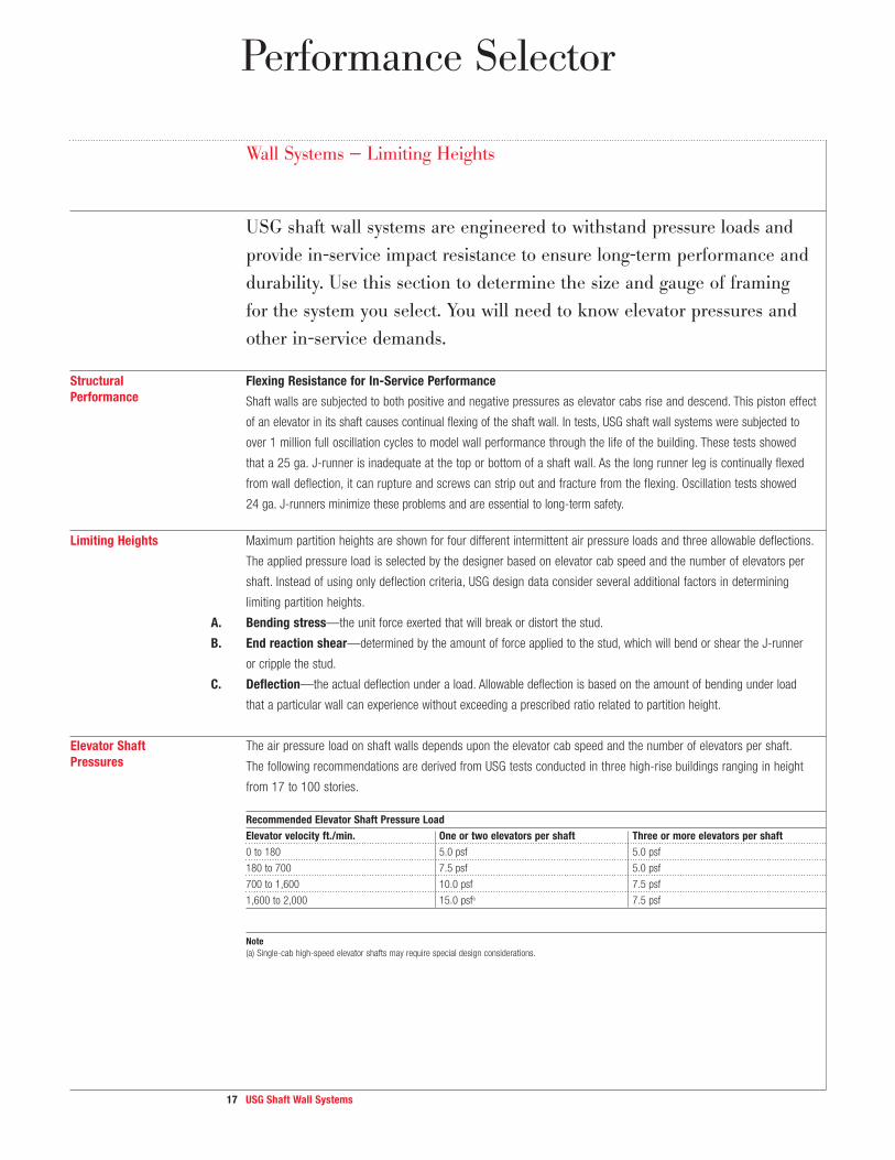
Wall Systems — Limiting Heights
USG shaft wall systems are engineered to withstand pressure loads and
provide in-service impact resistance to ensure long-term performance and
durability. Use this section to determine the size and gauge of framing
for the system you select. You will need to know elevator pressures and
other in-service demands.
Structural Flexing Resistance for In-Service Performance
Performance S h a f t w a lls a r e s u b je c t e d t o b o t h p o s itiv e a n d n e g a tiv e p r e s s u r e s a s e le v a t o r c a b s r is e a n d d e s c e n d . T h is p is t o n e f f e c t
o f a n e le v a t o r in it s s h a ft c a u s e s c o n tin u a l fle x in g o f t h e s h a ft w a ll. In t e s t s , USG s h a ft w a ll s y s t e m s w e r e s u b je c t e d t o
o v e r 1 m i l l i o n f u l l o s c i l l a t i o n c y c l e s t o m o d e l w a l l p e r f o r m a n c e t h r o u g h t h e l i f e o f t h e b u i l d i n g . T h e s e t e s t s s h o w e d
t h a t a 25 ga. J-runner is inadequate at the top or bottom of a shaft wall. As the long runner leg is continually flexed
from wall deflection, it can rupture and screws can strip out and fracture from the flexing. Oscillation tests showed
24 ga. J-runners minimize these problems and are essential to long-term safety.
Limiting Heights Maximum partition heights are shown for four different intermittent air pressure loads and three allowable deflections.
The applied pressure load is selected by the designer based on elevator cab speed and the number of elevators per
shaft. Instead of using only deflection criteria, USG design data consider several additional factors in determining
limiting partition heights.
A. Bending stress—the unit force exerted that will break or distort the stud.
B. End reaction shear—determined by the amount of force applied to the stud, which will bend or shear the J-runner
or cripple the stud.
C. Deflection—the actual deflection under a load. Allowable deflection is based on the amount of bending under load
that a particular wall can experience without exceeding a prescribed ratio related to partition height.
Elevator Shaft The air pressure load on shaft walls depends upon the elevator cab speed and the number of elevators per shaft.
Pressures The following recom men dations are derived from USG tests conducted in three high-rise buildings ranging in height
from 17 to 100 stories.
Recommended Elevator Shaft Pressure Load
Elevator velocity ft./min. One or two elevators per shaft Three or more elevators per shaft
0 to 180 5.0 psf 5.0 psf
180 to 700 7.5 psf 5.0 psf
700 to 1,600 10.0 psf 7.5 psf
1,600 to 2,000 15.0 psfa 7.5 psf
Note
(a) Single-cab high-speed elevator shafts may require special design considerations.

18 USG Shaft Wall Systems
1-Hr. Shaft Wall / Stair Wall (U415 System A)b 2-Hr. Shaftwall (U415 System C)b
Stud Type
and Size
Designation Allowable
Deflection
5 7.5 10 15 5 7.5 10 15
2-1/2" C-H
Studs
212CH25 L/120 11' 5" 10' 0" 9' 1" d 7' 11" d
— — — —
L/240 10' 7" 9' 3" 8' 4" d 7' 4" d
— — — —
L/360 9' 4" 8' 2" 7' 5" 6' 6" — — — —
212CH20 L/120 13' 5" 11' 8" 10' 8" 9' 3" — — — —
L/240 12' 3" 10' 9" 9' 9" 8' 6" — — — —
L/360 10' 10" 9' 6" 8' 7" 7' 6" — — — —
4" C-H Studs 400CH25 L/120 15' 2" 12' 5" 10' 9" d 8' 9" d 15' 2" 12' 5" 10' 9" d 8' 9" d
L/240 14' 5" 12' 5" 10' 9" d 8' 9" d 14' 5" 12' 5" 10' 9" d 8' 9" d
L/360 12' 9" 11' 2" 10' 1" d 8' 9" d 12' 9" 11' 2" 10' 1" d 8' 9" d
400CH20 L/120 20' 5" 17' 10" 16' 2" d 13' 4" d 20' 5" 17' 10" 16' 2" d 13' 4" d
L/240 17' 6" 15' 3" 13' 10" 12' 1" d 17' 6" 15' 3" 13' 10" 12' 1" d
L/360 15' 3" 13' 4" 12' 1" 10' 7" d 15' 3" 13' 4" 12' 1" 10' 7" d
6" C-H Studs 600CH20 L/120 26' 3" 21' 5" d 18' 7" d 15' 2" d 26' 3" 21' 5" d 18' 7" d 15' 2" d
L/240 24' 0" 20' 12" d 18' 7" d 15' 2" d 24' 0" 20' 12" d 18' 7" d 15' 2" d
L/360 21' 1" 18' 5" 16' 9" d 14' 8" d 21' 1" 18' 5" 16' 9" d 14' 8" d
Double 6"
E-Studse
600ES20 L/120 28' 0" 28' 0" d 28' 0" d 20' 0" d 28' 0" 28' 0" d 28' 0" d 20' 0" d
L/240 28' 0" 24' 9" 22' 6" d 20' 0" d 28' 0" 24' 9" 22' 6" d 20' 0" d
L/360 25' 3" 21' 9" 19' 6" 17' 3" d 25' 3" 21' 9" 19' 6" 17' 3" d
2-Hr. Shaftwall (U415 System B, D, F) 2-Hr. Stairwall (U415 System E)c
Stud Type
and Size
Designation Allowable
Deflection
5 7.5 10 15 5 7.5 10 15
2-1/2" C-H
Studs
212CH25 L/120 12' 4" 10' 10" 9' 10" d 8' 7" 12' 2" 10' 8" 9' 8" d 8' 5"
L/240 11' 4" 9' 11" 8' 12" d 7' 10" 11' 2" 9' 9" 8' 10" d 7' 9"
L/360 10' 4" 9' 1" 8' 3" 7' 2" 9' 10" 8' 7" 7' 10" 6' 10"
212CH20 L/120 14' 3" 12' 5" 11' 4" 9' 11" 14' 2" 12' 5" 11' 3" 9' 10"
L/240 12' 10" 11' 3" 10' 2" 8' 11" 13' 0" 11' 5" 10' 4" 9' 1"
L/360 11' 7" 10' 1" 9' 2" 8' 0" 11' 6" 10' 0" 9' 1" 7' 12"
4" C-H Studs 400CH25 L/120 17' 9" 14' 6" 12' 7" 10' 3" d 16' 4" 14' 3" d 12' 11" d 10' 7" d
L/240 15' 7" 13' 8" 12' 5" 10' 3" d 15' 2" 13' 3" d 12' 0" d 10' 6" d
L/360 13' 11" 12' 2" 11' 1" 9' 8" d 13' 4" 11' 8" 10' 7" 9' 3" d
400CH20 L/120 19' 11" 17' 4" 15' 9" 13' 10" d 19' 6" 17' 1" 15' 6" 13' 7" d
L/240 18' 1" 15' 9" 14' 4" 12' 6" 17' 11" 15' 8" 14' 3" 12' 5"
L/360 16' 2" 14' 1" 12' 10" 11' 3" 15' 10" 13' 10" 12' 7" 10' 12"
6" C-H Studs 600CH20 L/120 25' 4" 22' 2" 19' 8" d 16' 1" d 28' 0" 25' 1" d 21' 9" d 17' 9" d
L/240 21' 9" 19' 0" 17' 4" 15' 1" d 24' 10" 21' 9" d 19' 9" 17' 3" d
L/360 20' 0" 17' 6" 15' 11" 13' 11" 21' 11" 19' 2" 17' 5" 15' 2"
Double 6"
E-Studse
600ES20 L/120 28' 0" 28' 0" d 28' 0" d 20' 0" d 28' 0" 28' 0" d 28' 0" d 20' 0" d
L/240 28' 0" 26' 3" d 24' 0" d 20' 0" d 28' 0" 26' 0" d 23' 6" d 20' 0" d
L/360 26' 3" 23' 0" 21' 0" d 18' 3" d 25' 3" 22' 9" 20' 6" 18' 0" d
Wall Systems — Limiting Heights Table
Intermittent Air Pressure
Load (wind load)–psfa
Performance Selector

19 USG Shaft Wall Systems
3-Hr. Shaftwall (U415 System G) 3-Hr. Stairwall (U415 System H)c
Stud Type
and Size
Designation Allowable
Deflection
5 7.5 10 15 5 7.5 10 15
2-1/2" C-H
Studs
212CH25 L/120 12' 4" 10' 10" 9' 10" 8' 7" 12' 2" 10' 8" 9' 8" 8' 5"
L/240 11' 4" 9' 11" 8' 12" 7' 10" 11' 2" 9' 9" 8' 10" 7' 9"
L/360 10' 4" 9' 1" 8' 3" 7' 2" 9' 10" 8' 7" 7' 10" 6' 10"
212CH20 L/120 14' 3" 12' 5" 11' 4" 9' 11" 14' 2" 12' 5" 11' 3" 9' 10"
L/240 12' 10" 11' 3" 10' 2" 8' 11" 13' 0" 11' 5" 10' 4" 9' 1"
L/360 11' 7" 10' 1" 9' 2" 8' 0" 11' 6" 10' 0" 9' 1" 7' 12"
4" C-H Studs 400CH25 L/120 17' 9" 14' 6" 12' 7" 10' 3" d 16' 4" 14' 3" d 12' 11" d 10' 7" d
L/240 15' 7" 13' 8" 12' 5" 10' 3" d 15' 2" 13' 3" d 12' 0" d 10' 6" d
L/360 13' 11" 12' 2" 11' 1" 9' 8" d 13' 4" 11' 8" 10' 7" 9' 3" d
400CH20 L/120 19' 11" 17' 4" 15' 9" 13' 10" d 19' 6" 17' 1" 15' 6" 13' 7" d
L/240 18' 1" 15' 9" 14' 4" 12' 6" 17' 11" 15' 8" 14' 3" 12' 5"
L/360 16' 2" 14' 1" 12' 10" 11' 3" 15' 10" 13' 10" 12' 7" 10' 12"
6" C-H Studs 600CH20 L/120 25' 4" 22' 2" 19' 8" d 16' 1" d 28' 0" 25' 1" d 21' 9" d 17' 9" d
L/240 21' 9" 19' 0" 17' 4" 15' 1" d 24' 10" 21' 9" d 19' 9" 17' 3" d
L/360 20' 0" 17' 6" 15' 11" 13' 11" 21' 11" 19' 2" 17' 5" 15' 2"
Double 6"
E-Studse
600ES20 L/120 28' 0" 28' 0" d 28' 0" d 20' 0" d 28' 0" 28' 0" d 28' 0" d 20' 0" d
L/240 28' 0" 26' 3" d 24' 0" d 20' 0" d 28' 0" 26' 0" d 23' 6" d 20' 0" d
L/360 26' 3" 23' 0" 21' 0" d 18' 3" d 26' 3" 22' 9" 20' 6" 18' 0" d
4-Hr. Shaftwall (U415 System I)
Stud Type
and Size
Designation Allowable
Deflection
5 7.5 10 15
2-1/2" C-H
Studs
212CH25 L/120 12' 4" 10' 10" 9' 10" d 8' 7"
L/240 11' 4" 9' 11" 8' 12" d 7' 10"
L/360 10' 4" 9' 1" 8' 3" 7' 2"
212CH20 L/120 14' 3" 12' 5" 11' 4" 9' 11"
L/240 12' 10" 11' 3" 10' 2" 8' 11"
L/360 11' 7" 10' 1" 9' 2" 8' 0"
4" C-H Studs 400CH25 L/120 17' 9" 14' 6" 12' 7" 10' 3" d
L/240 15' 7" 13' 8" 12' 5" 10' 3" d
L/360 13' 11" 12' 2" 11' 1" 9' 8" d
400CH20 L/120 19' 11" 17' 4" 15' 9" 13' 10" d
L/240 18' 1" 15' 9" 14' 4" 12' 6"
L/360 16' 2" 14' 1" 12' 10" 11' 3"
6" C-H Studs 600CH20 L/120 25' 4" 22' 2" 19' 8" d 16' 1" d
L/240 21' 9" 19' 0" 17' 4" 15' 1" d
L/360 20' 0" 17' 6" 15' 11" 13' 11"
Double 6"
E-Studse
600ES20 L/120 28' 0" 28' 0" d 28' 0" d 20' 0" d
L/240 28' 0" 26' 3" d 24' 0" d 20' 0" d
L/360 26' 3" 23' 0" 21' 0" d 18' 3" d
Wall Systems — Limiting Heights Table
Notes
• See the Performance Selector for system references
and rated assembly details.
• Runners fasteners should widthstand 193 lb. single
shear and 200 lb. bearing force; attachment spacing
should not exceed 24".
• L/180 deflection information available upon request
from USG.
(a) Stud spacing of 24" o.c.
(b) For assembly single-layer board attached to studs.
(c) For assembly with single-layer board attached to
both sides of studs.
(e) Attachment of USG steel double 6" E-Stud for USG
shaft wall systems. The studs are to be attached
back-to-back (web-to-web) with pairs of 1/2" long
Type S-12 pan head screws installed in two rows,
spaced as widely appart as possible. The first and
last pairs of fasteners shall start within 6" of each
end of the studs. They shall then be spaced at a
maximum of 12" o.c.
Limiting Criteria:
c - practical limitation
d - deflection
f - bending
v - end reaction shear
Performance Selector

20 USG Shaft Wall Systems
Performance Selector
Wall Systems — Limiting Heights
Unlined Shafts Gypsum shaft walls have been used for many years for vent and air shafts. Their fire-resistant features and economical
dry construction make them ideal for this use. To function properly, vent and air shaft systems should be designed with
the following performance provisions:
1. Gypsum board surface temperature does not exceed 125 °F.
2. Separate approved liners should be installed in areas subject to continuous moisture overspray, condensation or air
stream temperature over 125 °F.
3. Air stream dew point temperatures are maintained below gypsum board surface temperature.
4. The assembly is constructed to withstand sustained design uniform air pressure loads not exceeding 10 psf. Startup
surge loads should not be greater than 1-1/2 times the design static load. (See table below for limiting heights.)
5. To ensure airtight construction, select appropriate sealants and apply where required.
Sustained Pressure Load–psf
2-Hr. Fire-Rated System 1-Hr. Fire-Rated System
Stud Type Designation Stud Allowable 5 10 5 10and Size Spacing deflection
2-1/2" C-H Studs 212CH-18 24" L/120 10'10" 8'7" 10'0" 7'11"
L/240 9'11" 7'10" 9'3" 7'4"
L/360 9'1" 7'2" 8'2" 6'6"
212CH-34 24" L/120 12'5" 9'11" 11'8" 9'3"
L/240 11'3" 8'11" 10'9" 8'6"
L/360 10'1" 8'0" 9'6" 7'6"
4" C-H Studs 400CH-18 24" L/120 14'6" 10'3" 12'5" 8'9"
L/240 13'8" 10'3" 12'5" 8'9"
L/360 12'2" 9'8" 11'2" 8'9"
400CH-34 24" L/120 17'4" 13'10" 17'10" 13'4"
L/240 15'9" 12'6" 15'3" 12'1"
L/360 14'1" 11'3" 13'4" 10'7"
6" C-H Studs 600CH-34 24" L/120 22'2" 16'1" 21'5" 15'2"
L/240 19'0" 15'1" 20'12" 15'2"
L/360 17'6" 13'11" 18'5" 14'8"
For more information, consult Progressive Engineering Report AER-09038 at p-e-i.com
Notes
Runner fasteners should withstand 193-lb. single shear and 200-lb. bearing force; attachment spacing should not exceed 24" o.c. (a) Use JR20 runner for this height.
21 USG Shaft Wall Systems
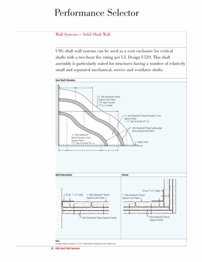
Wall Systems — Solid Shaft Wall
USG shaft wall systems can be used as a vent enclosure for vertical
shafts with a two-hour fire rating per UL Design U529. This shaft
assembly is particularly suited for structures having a number of relatively
small and separated mechanical, service and ventilator shafts.
Vent Shaft Elevation
Wall Intersection Corner
Note
Limiting height of system is 12.0". Install panels vertically and full height only.
USG Sheetrock® Brand setting-type
joint compound lamination
1/2" USG Sheetrock® Brand Firecode C Core
Gypsum Panel– 11/2" type G screws 24" o.c.
1/2" USG Sheetrock®
Brand Firecode C Core
Gypsum Panel – 11/2" type G screws 24" o.c.
1" USG Sheetrock® Brand
Gypsum Liner Panel –
15/8" type S screws
12" o.c. to angle
Angle runner
3'
2' 2'
4'
1' 4' 2'
25 ga. 1" x 2" angle
USG Sheetrock® Brand Gypsum Panels
1" USG Sheetrock® Brand
Gypsum Liner Panel
l
24 ga. 2" x 2" angle
USG Sheetrock® Brand
Gypsum Panels
1" USG Sheetrock® Brand
Gypsum Liner Panel
Performance Selector
22 USG Shaf t Wall Systems
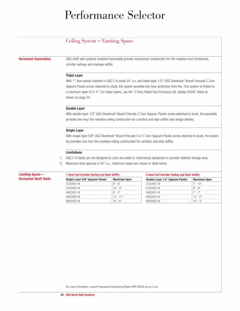
Ceiling System — Limiting Spans
Horizontal Assemblies USG shaft wall systems installed horizontally provide economical construction for fire-resistive duct enclosures,
corridor ceilings and stairway soffits.
Tr iple Layer
With 1" liner panels inserted in USG C-H studs 24" o.c. and triple-layer 1/2" USG Sheetrock® Brand Firecode C Core
Gypsum Panels screw-attached to studs, the system provides two-hour protection from fire. This system is limited to
a maximum span of 5'-4". For larger spans, use the “2-Hour Rated Duct Enclosure (UL Design K504)” detail as
shown on page 24.
Double Layer
With double-layer 1/2" USG Sheetrock® Brand Firecode C Core Gypsum Panels screw-attached to studs, the assembly
provides two-hour fire-resistive ceiling construction for corridors and stair soffits (see design details).
Single Layer
With single-layer 5/8" USG Sheetrock® Brand Firecode X or C Core Gypsum Panels screw-attached to studs, the assem-
bly provides one-hour fire-resistive ceiling construction for corridors and stair soffits.
L imitat ions
1. USG C-H studs are not designed to carry live loads or mechanical equipment or provide material storage area.
2. Maximum stud spacing is 24" o.c.; maximum spans are shown in table below.
Limit ing Spans—
Horizontal Shaf t Walls
For more information, consult Progressive Engineering Report AER-09038 at p-e-i.com
Performance Selector
1-Hour Exit Corr idor Ceiling and Stair Sof f its
Single-Layer 5/8" Gypsum Panels c Maximum Span
212CH25-18 8' - 6"
212CH20-34 10' - 4"
400CH25-18 9' - 3"
400CH20-34 14' - 11"
600CH20-34 18' - 6"
2-Hour Exit Corr idor Ceiling and Stair Sof f its
Double-Layer 1/2" Gypsum Panels c Maximum Span
212CH25-18 7' - 10"
212CH20-34 9' - 8"
400CH25-18 7' - 7"
400CH20-34 14' - 0"
600CH20-34 15' - 3"

23 USG Shaft Wall Systems
Ceiling Membrane
2-Hr. Rated Assembly – Horizontal Membrane or Metal Duct Enclosure
For more information consult Progressive Engineering Report AER-09038 at p-e-i.com. For spans greater than 5'-4", see UL Design # K504 on page 24.
Ceiling Membrane of 1-Hr. Egress Corridors and Stair Soffits (see AER-09038) Ceiling Membrane of 2-Hr. Egress Corridors and Stair Soffits (see AER-09038)
USG Sheetrock®
Brand Acoustical Sealant
USG Sheetrock®
Brand Acoustical Sealant
Duct surface
Rotated Section
1" USG Sheetrock® Brand
Gypsum Liner Panel
USG steel C-H studUSG steel J-runner
Fastener 24" o.c. max. (shear
and withdrawal resistance as
required by specific design conditions)
Fastener 24" o.c. max. (shear
and withdrawal resistance as
required by specific design conditions)
USG Sheetrock®
Brand Gypsum Panels
1/2" type S pan
head screw at
12" o.c. (attach
both sides of C-H
stud and J-runner
at top and bottom
of stud)
max. height 4'-0"
max. span 5'- 4"
Design Details
USG steel J-runner
Fasteners as
required 24" o.c.
USG Sheetrock®
Brand Gypsum Panels
1" USG Sheetrock®
Brand Gypsum Liner Panel
USG Sheetrock®
Brand Acoustical Sealant
USG steel
C-H studUSG steel J-runner
Fasteners as
required 24" o.c.
USG Sheetrock®
Brand Gypsum Panel
1" USG Sheetrock®
Brand Gypsum Liner Panel
USG Sheetrock®
Brand Acoustical Sealant
USG steel
C-H stud
Refer to span table on page 22.Refer to span table on page 22.

24 USG Shaft Wall Systems
Ceiling Membrane
2-Hr. Duct Enclosure (UL Design K504)
2-Hr. Rated Ceiling Assembly (UL Design K504)
Corner bead
Steel strap
RC-1 resilient
channels 16" o.c.
Steel studs Perimeter channel
Duct
5/8" USG Sheetrock®
Brand Firecode Core
Gypsum Panels or 5/8"
USG Sheetrock® Brand
UltraLight Panels Firecode X
5/8" USG Sheetrock®
Brand Firecode Core
Gypsum Panels or 5/8"
USG Sheetrock® Brand
UltraLight Panels Firecode X
5/8" USG Sheetrock®
Brand Firecode
Core Gypsum
Panels or 5/8"
USG Sheetrock®
Brand UltraLight
Panels Firecode X
1" USG Sheetrock® Brand
Gypsum Liner Panels
RC-1 resilient
channels 16" o.c.
Steel strap
Steel studs
5/8" USG Sheetrock®
Brand Firecode Core
Gypsum Panels or 5/8"
USG Sheetrock® Brand
UltraLight Panels Firecode X
5/8" USG Sheetrock®
Brand Firecode Core Gypsum
Panels or 5/8" USG Sheetrock®
Brand UltraLight Panels Firecode X
Design Details
Vertical assembly shown is
UL Design #U415 System B.

25 USG Shaft Wall Systems
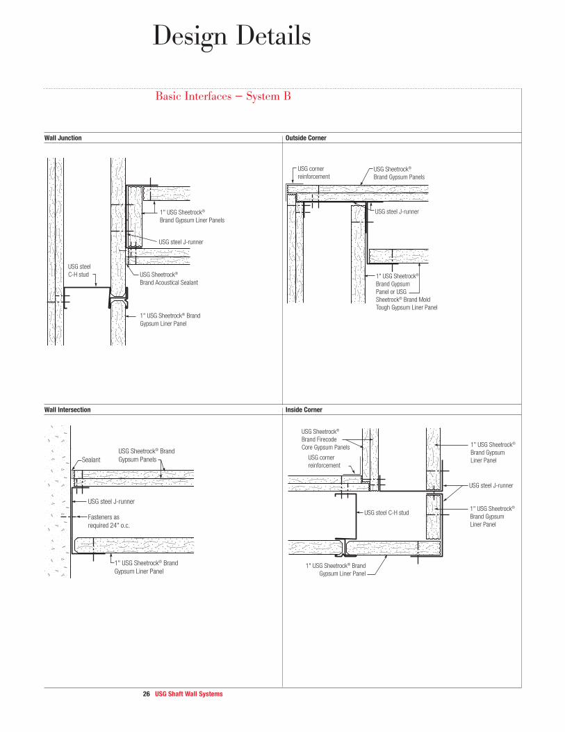
Design Details
Basic Interfaces — System B
Head Section (UL System HW-D-0603) Base Section (UL System BW-S-0016)
Call-Button Box
USG steel C-H stud
USG Sheetrock®
Brand Acoustical Sealant
USG steel J-runner
USG Sheetrock® Brand
Firecode Core Gypsum Panels
5/8" max.1" min.
3/8" to 1/2"
USG Sheetrock® Brand
Gypsum Liner Panels USG Sheetrock® Brand Acoustical Sealantas required for sound
1" USG Sheetrock® Brand Gypsum Liner Panels
Gypsum panel cant screw–attached to vertical studs(for projections over 4")
USG steel J-runner
over
4"
75˚min.
USG steel C-H stud
USG Sheetrock® Brand Firecode Core Gypsum Panels
4" min
USG Sheetrock®
Brand Firecode Core
Gypsum Panels
Call-button box
25 ga. steel strip
(6" x 12" min.)
1" USG Sheetrock® Brand
Gypsum Liner Panels
26 USG Shaft Wall Systems
Wall Junction Outside Corner
Wall Intersection Inside Corner
USG steel J-runner
USG corner
reinforcement
USG steel C-H stud
USG Sheetrock®
Brand Firecode
Core Gypsum Panels
1" USG Sheetrock® Brand
Gypsum Liner Panel
1" USG Sheetrock®
Brand Gypsum
Liner Panel
1" USG Sheetrock®
Brand Gypsum
Liner Panel
USG steel J-runner
Fasteners as
required 24" o.c.
USG Sheetrock® Brand
Gypsum Panels
1" USG Sheetrock® Brand
Gypsum Liner Panel
Sealant
USG steel J-runner
USG corner
reinforcementUSG Sheetrock®
Brand Gypsum Panels
1" USG Sheetrock®
Brand Gypsum
Panel or USG
Sheetrock® Brand Mold
Tough Gypsum Liner Panel
USG Sheetrock®
Brand Acoustical Sealant
USG steel J-runner
USG steel
C-H stud
1" USG Sheetrock®
Brand Gypsum Liner Panels
1" USG Sheetrock® Brand
Gypsum Liner Panel
Basic Interfaces — System B
Design Details

27 USG Shaft Wall Systems
Design Details
Basic Interfaces — System B
Outlet/Switch Box Control Joint in 2-Hr. Shaftwalls
Stair Hanger and Rod Application Cross-Section at Stair Hanger
USG Sheetrock®
Brand Gypsum Panels
Outlet box
C-H stud
1" USG Sheetrock® Brand
Gypsum Liner Panels
1" USG Sheetrock® Brand
Gypsum Liner Panel
Hanger rod
Steel angle
Stair landing
Stair stringer
Stairwell side
USG Sheetrock®
Brand Gypsum Panel
USG steel C-H
stud 24" o.c.
Hanger rod
1" USG Sheetrock® Brand
Gypsum Liner Panel
l
USG Sheetrock®
Brand Gypsum Panel
USG steel J-runner
11/4"
4"
1/2"
5/8" USG Sheetrock®
Brand Firecode Core
Gypsum Panels
5/8" USG Sheetrock®
Brand Firecode Core
Gypsum Panels
Control joint15/8" type S screws
1" USG Sheetrock® Brand
Gypsum Liner Panels
1" type S screws
28 USG Shaft Wall Systems
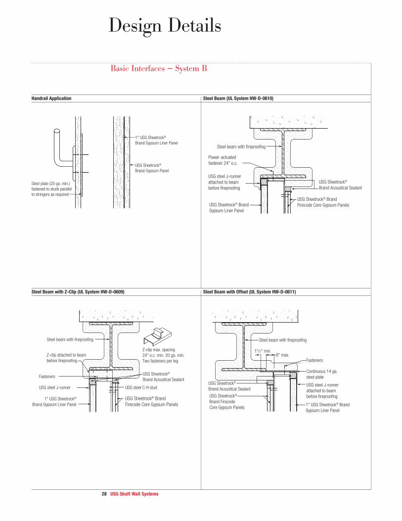
Handrail Application Steel Beam (UL System HW-D-0610)
Steel Beam with Z-Clip (UL System HW-D-0609) Steel Beam with Offset (UL System HW-D-0611)
Z-clip attached to beam
before fireproofing
Z-clip max. spacing
24" o.c. min. 20 ga. min.
Two fasteners per leg
USG steel J-runner USG steel C-H stud
Fasteners
Steel beam with fireproofing
USG Sheetrock® Brand
Firecode Core Gypsum Panels
USG Sheetrock®
Brand Acoustical Sealant
1" USG Sheetrock®
Brand Gypsum Liner Panel
USG steel J-runner
attached to beam
before fireproofing
Continuous 14 ga.
steel plate
8" max.11/2" min.
USG Sheetrock®
Brand Acoustical Sealant
Fasteners
Steel beam with fireproofing
1" USG Sheetrock® Brand
Gypsum Liner Panel
USG Sheetrock®
Brand Firecode
Core Gypsum Panels
Steel plate (20 ga. min.)
fastened to studs parallel
to stringers as required
USG Sheetrock®
Brand Gypsum Panel
1" USG Sheetrock®
Brand Gypsum Liner Panel
USG steel J-runner
attached to beam
before fireproofing
Power
Steel beam with fireproofing
-actuated
fastener 24" o.c.
USG Sheetrock®
Brand Acoustical Sealant
USG Sheetrock® Brand
Gypsum Liner Panel
USG Sheetrock® Brand
Firecode Core Gypsum Panels
Basic Interfaces — System B
Design Details
29 USG Shaft Wall Systems
Design Details
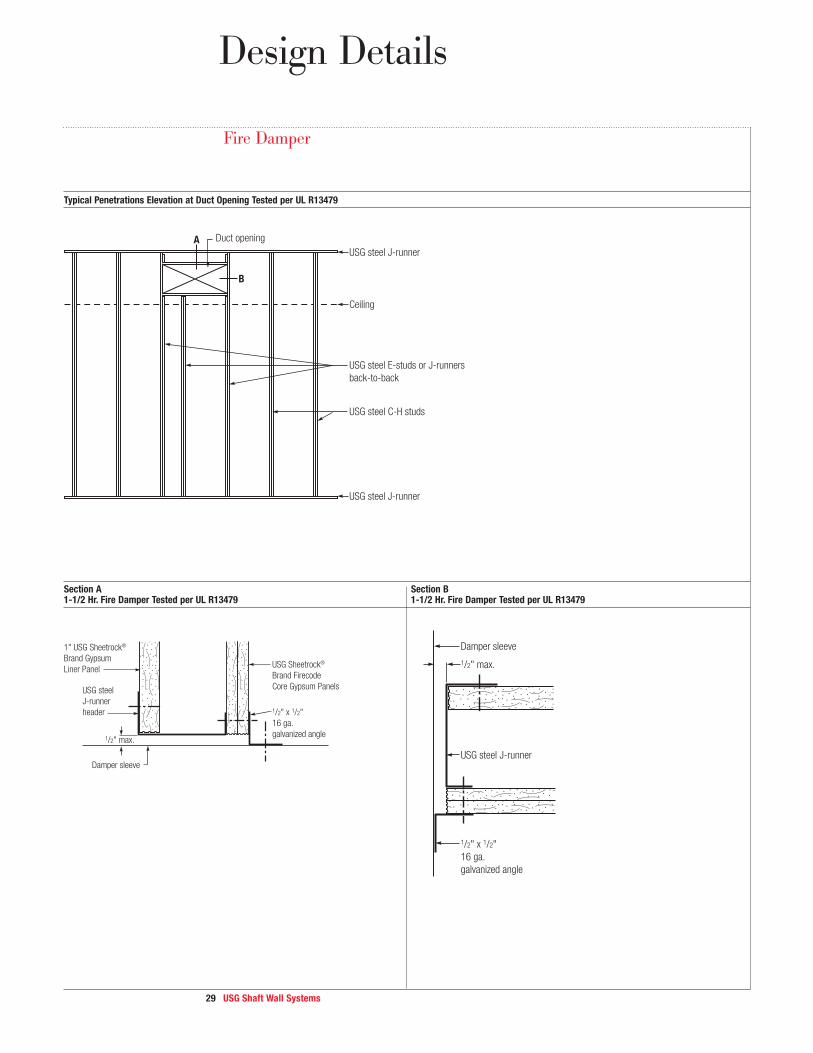
Fire Damper
Typical Penetrations Elevation at Duct Opening Tested per UL R13479
Section A Section B 1-1/2 Hr. Fire Damper Tested per UL R13479 1-1/2 Hr. Fire Damper Tested per UL R13479
1/2" x 1/2"
16 ga.
galvanized angle
Damper sleeve
1/2" max.
USG Sheetrock®
Brand Firecode
Core Gypsum Panels
1" USG Sheetrock®
Brand Gypsum
Liner Panel
USG steel
J-runner
header
1/2" x 1/2"
16 ga.
galvanized angle
Damper sleeve
1/2" max.
USG steel J-runner
USG steel J-runner
USG steel J-runner
Duct opening
B
A
USG steel E-studs or J-runners
back-to-back
Ceiling
USG steel C-H studs

30 U S G S h a f t W a l l S y s t e m s
Elevator Door Framing
E l e v a t o r D o o r F r a m i n g E l e v a t o r D o o r R o u g h O p e n i n g
Section A-A Detail
Notes
1. Framing at elevator door shall be a minimum 4" studs and runners 20 gauge.
2. Horizontal placement of liner panel and C-H Studs per UL Design U437.
3. Flanges of the jamb strut must be continuously braced by screw connections to the liner and face panels 12" o.c.
4. For doors greater than 5' wide and/or transom heights greater than 4', reinforce the 400JS-34 with a nested 400ES-34.
USG steel J-runner
USG steel J-runner
10'-0"
max
10'-0"
max
USG steel J-runner
USG steel
J-runner header
5'-0" max. opening
20 ga. jamb strut
20 ga. jamb strutUSG steel
J-runner
USG steel J-runner
USG steel
J-runner
Screw attached
both sides
Screw attached
both sides
Screw attached
both sides
A
A
USG C-H studUSG C-H stud
1" USG Sheetrock®
Brand Gypsum
Liner Panel
USG jamb strut
Fasten both
sides of C-H
stud to J runner
1" USG Sheetrock®
Brand Gypsum
Liner Panel
Screw attach
at bottom leg
of C-H stud
USG Sheetrock®
Brand Firecode
Core Gypsum Panels
Design Details

3 1 USG Shaft Wall Systems
Wall Systems – C-H Studs and Liner Panels Installed Horizontally
Horizontal Shaftwall Elevation per UL Design U437 Section C-C Head Section
Section B-B Wall Intersection Section D-D Base Section
USG steel J-runner
Structural member
" USG Sheetrock®
Brand Firecode Core
Gypsum Panels
1"USG Sheetrock®
Brand Acoustical
Sealant
1" USG Sheetrock® Brand
Gypsum Liner Panel
5/8
USG steel J-runner
USG Sheetrock® Brand Acoustical Sealant
Locate screws
to avoid studs
3/8" J-runner to stud1/2" J-runner to panel
USG steel C-H stud
5/8" USG Sheetrock®
Brand Firecode Core
Gypsum Panels
1" USG Sheetrock®
Brand Gypsum
Liner Panels
Design Details
Sealant
USG steel J-runner
1" USG Sheetrock® Brand
Gypsum Liner Panel
5/8" USG Sheetrock®
Brand Firecode Core
Gypsum Panels
Structural member
USG steel J-runners
USG steel
J-runner header
A
A
USG C-H studs
USG Sheetrock® Brand
Gypsum Liner Panels
B B
C
C
D
D
Note
Horizontal framing shall be a minimum 4" C-H Studs and runners 20 gauge.
3 2 U S G S h a f t W a l l S y s t e m s
Good Design Practices
Use this section as a reference if questions arise during the design or
application of USG shaft wall systems.
This section is an overview of good design, application, installation
and safety considerations that should be addressed when USG products
and systems are used. This section outlines some major issues, but is not
intended to be comprehensive.
We recommend that architects and contractors seek the assistance of
safety professionals, especially at the construction site, because there are
many factors to consider that are not included here. For more detailed
information on safety and material handling, please refer to Chapter 13 of
The Gypsum Construction Handbook.
1 S y s t e m P e r f o r m a n c e USG conducts tests on products and systems to meet performance requirements specified by various agencies. Upon
written request we will provide test certification for published fire, sound, structural and other pertinent data covering
systems designed and constructed according to our published specifications. Substitutions of any of the components
are not recommended and are not supported by USG.
S t a n d a r d s
The following standards apply:
ASTM C1396: Standard Specification for Gypsum Board
ASTM C1658: Standard Specification for glass-mat Gypsum Panels
ASTM C1325: Standard Specification for Non-Asbestos Fiber-Mat Reinforced Cementitious Backer Units
ASTM C1278: Standard Specification for Fiber-Reinforced Gypsum Panel
ASTM C840: Standard Specification for Application and Finishing of Gypsum Board
ASTM C754: Standard Specification for Installation of Steel Framing Members to Receive Screw-Attached Gypsum
Board, Backing Board, or Water-Resistant Backing Board
ASTM C645: Standard Specification for Non-Load (Axial) Bearing Steel Studs, Runners (Track), and Rigid Furring
Channels for Screw Application of Gypsum Board
ASTM C475: Standard Specification for Joint Treatment Materials for Gypsum Wallboard Construction
ASTM C1002: Standard Specification for Steel Drill Screws for the Application of Gypsum Board
ASTM C1047: Standard Specification for Accessories for Gypsum Wallboard and Gypsum Veneer Base
ASTM D3273: Standard Test Method for Resistance to Growth of Mold on the Surface of Interior Coatings
in an Environmental Chamber
2 F i r e R e s i s t a n c e Use fire test data to compare and select materials and assemblies, and to secure acceptance by the authority having
jurisdiction. SA100, Fire-Resistant Assemblies, shows tested fire resistance for various systems.
For assemblies tested at Underwriters Laboratories Inc. (UL), ratings are specific to the designs tested, and do not
necessarily apply to alternate products or construction. For example, insulation may not be added to floor- or roof-ceiling
assemblies, unless described in the UL design. Addition of insulation in the concealed space between the ceiling membrane

33 USG Shaft Wall Systems
Good Design Practices
and the floor or roof structure may reduce the hourly rating of an assembly by causing premature disruption of the ceiling
membrane and/or higher temperatures on structural components under fire exposure conditions.
Increasing the size or gauge of the stud (e.g., 2-1/2" C-H stud 25 gauge to 4" C-H stud 20 gauge) does not affect
the fire resistance rating of the assembly.
For more detailed information, refer to the system fire resistance Performance Selector on pages 14-15.
3 Structural Criteria Building structure supporting USG Shaftwall system must be capable of withstanding the loads applied by Shaftwall assemblies.
Interior non-bearing partitions such as USG shaft wall are not designed to carry axial loads. Limiting heights are based on
stress or deflection limits for lateral loads specified in the Performance Selector of this guide. Height limitations depend on the
gauge of the steel used, dimensions of the stud, stud spacing, and the allowable deflection limit. For limiting height tables,
see page 17; for horizontal shaft wall span table, see page 20; and for limiting heights, unlined return air shafts, see page 18.
Note: Size and gauge of the studs are specified in the limiting heights tables. Other sizes and gauges have not been
evaluated for performance.
4 Control Joints — Locating control joints is the responsibility of the design professional/architect. Integrate these suggestions with
Building Movement project conditions when determining specific locations for control joints.
“Control joint” is a general term for methods used to minimize (not eliminate the potential for) cracking in partitions
and ceilings. Specifically, a control joint minimizes cracking in the face of a partition or ceiling. At the perimeter of a partition
or ceiling, it is called a perimeter relief joint.
A control joint is effective in minimizing cracking caused by tensile or compressive movement in a membrane resulting
from thermal, hygrometric and structural movement. Isolate shaft wall surfaces with control joints or other means where:
– construction changes within the plane of the shaft wall
– shaft wall run exceeds 30'
– expansion or control joints occur through the building itself
– in stairwells at each floor level
Ceiling-height door frames may be used as control joints. Less-than-ceiling-height door frames should have control joints
extending to ceiling from both corners on both sides of the partition. Treat window openings in same manner as doors.
Zinc control joints, when properly insulated and backed by gypsum panels, have been fire-endurance tested for use in
one- and two-hour fire-rated walls.
Proper installation of control joints in partitions and ceilings requires breaking the gypsum panels or lath behind the
control joint. In ceiling construction, the framing should also be broken. In partitions, separate studs are used on each side
of the joint with the runner track separated at that location.
5 Pressure Loads — Where shaft walls enclose elevator and return air vents, and intermittent pressures up to 15 psf are expected,
Minimizing Wind USG Sheetrock® Brand Acoustical Sealant is recommended at intersections with floors, ceilings, columns, ducts, etc. to seal
Noise peripheries and penetrations and minimize whistling and dirt accumulation due to air movement. Sealant selection including
joint treatment, surface coatings and details to seal the wall under these sustained pressures must be provided
by the designer. See pages 16-17 for information on evaluating pressure loading and selecting the appropriate framing
components based upon these design criteria.
34 USG Shaft Wall Systems
6 Pressure Loads — Shaft walls may be used for air handling with sustained pressures up to 10 psf. When air pressure exceeds 10 psf,
Air Handling air handling should be contained with a metal duct. See pages 18-19 for information about air handling and vent
shaft enclosures.
7 Penetrations Penetrations of the shaft wall, such as door frames and duct openings, require additional reinforcement at corners to
distribute concentrated stresses if a control joint is not used. Penetrations greater than 48" wide require supplemental
support for the shaft wall at the opening. Where access panels or large duct penetrations occur in shafts having pressure
loads, headers, sills and adjacent channels may require reinforcing to properly distribute these loads.
8 Sound Control Use sound test data to compare and select materials and constructions. These data frequently are essential for securing
compliance by the agency having jurisdiction. See SA200, Acoustical Assemblies, for acoustical performance.
Sound control refers to the ability to attenuate sound passing through a partition. The Sound Transmission Class (STC) is a
widely used rating of sound attenuation performance. It is relatively accurate for speech sounds but not for music, mechanical
equipment noise or any sound with substantial low-frequency energy. It is tested per ASTM E90 and rated per ASTM E413.
See the Performance Selector for the STC ratings for USG shaft wall systems.
Sound tests are conducted under ideal laboratory conditions per ASTM procedures. USG products are assembled in a
specific manner to meet the requirements of these ASTM procedures. Substitution of materials other than those tested or
deviation from the specified construction may adversely affect performance.
Field performance depends on building design and careful attention to detailing and workmanship. Where these
partitions are used for sound control, seal the partition perimeter with 1/4" min. round bead of USG Sheetrock® Brand
Acoustical Sealant. Seal around all penetrations.
9 Moisture Understanding water and mold and its impact on the construction process and building materials are integral to
and Mold good design and construction practices. USG offers references and additional sources that reinforce good design,
construction and maintenance practices. These practices are generally recognized as necessary to minimize moisture-
related problems and the growth of mold in a building environment. If you have additional questions, please contact those
sources or USG.
The best way to address mold is to make sure that building materials do not get wet before and during installation and are
not exposed to moisture inside the finished building. See Moisture/Mold in the Performance Testing section for more information.
10 Air and Water Flashing and sealants as shown in the construction documents and as selected by the architect and/or structural engineer
Infiltration should be provided to resist air and water infiltration. The flashing and sealants selected shall be installed in a workmanlike
manner in appropriate locations to maintain continuity of air/water barriers, particularly at windows, doors and other
penetrations of exterior wall.
11 Vapor Retarders Water vapor control must always be considered in the design of exterior wall systems. Humidity and temperature conditions
may require the installation of a vapor retarder to prevent moisture condensation within the wall and the resulting damage.
To determine the necessity and location of vapor retarders, a water vapor transmission and dew point analysis of the layered
wall assembly should be conducted by a qualified engineer.
Good Design Practices

35 USG Shaft Wall Systems
Good Design Practices
12 Product Handling Gypsum Panels
and Storage Protect all gypsum products from exposure to excessive or continuous moisture and the elements elements before, during
and after installation. Eliminate sources of moisture immediately.
Metal Framing Protection
Give light-gauge metal components such as steel studs and runners, furring channels and resilient channels adequate protection
in the warehouse and on the jobsite against rusting caused by moisture. In marine areas such as the Caribbean, Florida and the
Gulf Coast where chloride and sea salt are present in combination with excessively high humidity, use of components that offer
increased protection against corrosion is recommended.
13 Application Call-Button Floor Indicator and Electric Boxes
Shaft walls will accommodate outlet boxes with depths up to the stud width. See page 25 for details.
Framing Attachment
Runners and studs attached to beams or columns may need to be installed before steel is spray-fireproofed. Excess
fireproofing should be removed from runners and studs before installing shaft wall liner and sealant.
USG Sheetrock® Brand Gypsum Liner Panel Application – Butt Joints
When an installation of USG shaft wall height exceeds maximum available panel length, it is necessary to
incorporate a butt joint between two liner panels. Stagger butt joints in adjacent panels top and bottom to prevent
a continuous horizontal joint. Joint should be located in top or bottom third of wall. Horizontal joints need not be backed
by steel framing to maintain the fire-rating of the assembly.
14 Painting Systems Painting products and systems should be used that comply with recommendations and requirements in appendices of ASTM
C840. For priming and decorating with paint, texture or wall covering, follow manufacturer’s directions.
All surfaces, including applied joint compound, must be thoroughly dry, dust-free and not glossy. Prime with USG
Sheetrock® Brand First Coat or with an undiluted, interior latex flat paint with high-solids content. Allow to dry before decorating.
To improve fastener concealment, where gypsum panel walls and ceilings will be subjected to severe artificial or natural
side lighting and decorated with a gloss paint (egg shell, semi-gloss or gloss), the gypsum panel surface should be skim
coated with joint compound to equalize suction and texture differences between the drywall face paper and the finished joint
compound before painting. USG Sheetrock® Brand Tuff-Hide Primer-Surfacer skims and primes in a single application.
15 Screws USG DurockTM Brand Fasteners for Steel Framing
USG Durock Tile Backer Screws for steel framing Type G screws; 1-5/8", 1-1/4".
USG Fiberock® Brand Panel Fasteners for Steel Framing
Use corrosion-resistant Type S-12 buglehead screws for 25-12 ga. steel framing. When using 25 ga. steel framing,
fasteners should be spaced no greater than 8" o.c. Fasteners must be of sufficient length to ensure a minimum of 3/8"
penetration into steel framing.
16 Steel Door Frames Ordered separately, should be at least 16 ga. steel, shop primed, and have throats accurately formed to overall
thickness of the shaft wall plus 3/32" minimum. They should be anchored at floor with 16 ga. steel plates welded to trim
flanges, with provision for two power-driven anchors or equal per plate. Jamb anchors should be 18 ga. steel welded in jamb
and screw-attached to anchors.
USG reserves the right to make changes or improvements in the design of all catalogued items without notice and without
obligation to incorporate these changes or improvements in items already manufactured.

36 USG Shaft Wall Systems
This guide specification is provided to assist you in specification of USG shaft wall systems. If you have additional questions or would like more information regarding this or other USG products and systems, please contact USG at 800 USG.4YOU or visit usgdesignstudio.com
Part 1: General
1.1 Drawings and general provisions of the project contract, including General and Supplementary Conditions and Division 1
Related Documents Specification Sections, apply to this Section. USG System Folder SA926 – USG Shaft Wall Systems.
1.2 Specify the appropriate USG shaft wall system to meet project requirements for fire resistance, structural
Scope performance, sound control and aesthetics.
1.3 A. This section includes the following USG shaft wall systems
Summary 1. Vertical shaft enclosures
2. Stair enclosures
3. Horizontal assemblies
4. Vent shaft enclosures
B. Related Sections:
1. Division 9 USG Sheetrock® Brand Gypsum Panels and assemblies
2. Division 9 USG Imperial® Brand Gypsum Base and Veneer Plaster Assemblies
1.4 A. Shaft Wall: An assembly of steel framing, gypsum boards and other materials used to enclose elevator shafts,
Definitions stairways, air shafts and mechanical components.
B. Gypsum Board Construction Terminology: Refer to ASTM C11 for definition of terms for gypsum board construction not
defined in this document.
1.5 A. The systems are UL Listed for fire resistance.
Performance B. System fire-resistance testing with elevator door manufacturer at UL.Requirements
C. Fire-resistance tested penetration details for call-button boxes and position indicators.
D. Oscillation tested to 1 million cycles to ensure performance of the life of the building.
E. UL Listed fire damper application.
F. Air Pressure Loads—Select based on project requirements. See details in this brochure for USG shaft wall
system data.
G. Deflection Limit—Select based on project requirements. See details in this brochure for USG shaft wall
system data.
H. STC Rating—Select based on project requirements.
I. Hardened Shafts—Where required by code, for buildings classified as high-rise buildings, special provisions
may be required.
1.6 A. Product and System Data – Submit system folder SA926, which can be downloaded at usg.com.
Submittals B. Submit certification of manufacturer compliance with fire and sound requirements indicated.
C. Fire rating compliance shall include verification of compatibility with labeled elevator door frame installation and test
verification of call box and similar penetrations.
Application Guide Specifications

37 USG Shaft Wall Systems
Application Guide Specifications
1.7 A. Deliver materials in their original unopened packages bearing manufacturer identification.
Delivery, Storage B. Protect materials from wetting and damage from weather, direct sunlight, surface contamination, corrosion, constructionand Handling
traffic and other causes. of Materials
C. Warning: Store all USG Sheetrock® Brand Gypsum Panels flat. Panels are heavy and can fall over, causing serious injury
or death. Do not move unless authorized.
1.8 A. All materials shall be suitably protected from the weather during installation to prevent damage to the shaft wall.
Project Conditions B. Install gypsum panels following environmental conditions, room temperatures and ventilation specified in the USG
Gypsum Construction Handbook.
1.9 A. Protect USG shaft wall system and components from moisture before, during and after installation.
Quality Assurance Eliminate sources of moisture immediately.
B. Fire-Resistance Rated Assemblies: Provide UL Design Number (e.g., U415) for basic systems.
C. Sound-Rated Assemblies (STC)—Provide sound-rated system whose materials and construction comply with
requirements of ASTM E90 and are classified according to ASTM E413 by a qualified testing agency.
D. Preinstallation Conference – Conduct conference at project site. Review methods and procedures for work related to
USG shaft wall system assemblies.
Part 2: Products
2.1 A. Supply materials manufactured by or for the United States Gypsum Company that comply with requirements of
Manufacturer fire-resistance rated assemblies indicated in System Folder SA926.
B. Basis of Design—USG shaft wall system
2.2 A. Gypsum Liner Panels—ASTM C1396, 1" USG Sheetrock® Brand Gypsum Liner Panels, 100% recycled green face
Materials and back paper, beveled edge, 24" wide, lengths as required. Stamped with UL Classification label documenting
UL Classifications for fire resistance, surface burning characteristics, and noncombustibility. Panels should also be
identified with the following language: “USG Sheetrock® Brand Gypsum Liner Panel, a Component of United States
Gypsum Company Fire-Rated Systems.”
B. USG Sheetrock® Brand Mold Tough Gypsum Liner Panels—ASTM C1396, 1" USG Sheetrock® Brand Mold Tough
Gypsum Liner Panels, 100% recycled blue face and back paper, beveled edge, 24" wide, lengths as required. Stamped
with UL Classification label documenting UL Classifications for fire resistance, surface burning characteristics, and
noncombustibility. Panels should also be identified with the following language: “USG Sheetrock® Brand Mold Tough
Gypsum Liner Panel, a Component of United States Gypsum Company Fire-Rated Systems.”
C. USG Sheetrock® Brand Glass-Mat Liner Panels—ASTM C1658, 1" USG Sheetrock® Brand Glass-Mat Liner Panels,
moisture- and mold-resistant gypsum core encased in a moisture- and mold-resistant glass mat on both sides, 24"
wide, lengths as required. Stamped with UL Classification label documenting UL Classifications for fire resistance,
surface burning characteristics and noncombustibility. Panels should also be identified with the following language:
“USG Sheetrock® Brand Glass-Mat Liner Panel, a Component of United States Gypsum Company Fire-Rated Systems.”
38 USG Shaft Wall Systems
D. Gypsum Wallboard—ASTM C1396, (1/2") (5/8") (3/4") (select thickness), 4' wide, tapered edge, USG Sheetrock®
Brand Gypsum Panels, (USG Firecode Core) (USG Firecode C Core) (USG Ultracode Core) (USG Mold Tough Firecode
Core), ASTM C1287 (USG Fiberock® Brand Aqua-Tough Interior Panels) (USG Fiberock® Brand Abuse-Resistant Interior
Panels) (select core type), lengths as required. Identified with UL Classification label.
E. Gypsum Base for Gypsum Veneer Plaster—ASTM C1396, (1/2") (5/8") (select thickness), 4' wide, USG Imperial®
Brand Gypsum Base (USG Firecode Core) (USG Firecode C Core) (select core type), lengths as required.
F. Cement Board—ASTM C1325, USG Durock® Brand Cement Board, 1/2" and 5/8" thickness, 48" width x 96" length.
G. Gypsum Wallboard and Gypsum Base Joint Treatment Materials—Select a USG Interior Finishing System
(see product folder J1424).
H. Fasteners—ASTM C1002, Screws: (3/8") (1/2") Type (S) (S-12) pan head; 5/8" Type S-12 low profile head; (1")
(1-5/8") (2-1/4") Type S bugle head. USG Durock™ Brand Tile Backer Screws for steel framing: 1-5/8".
Type G screws: 1-1/2".
I. Metal Trim—ASTM C1047, No. (200A) (200B) (401) (402) (701B) (801B).
J. USG Sheetrock® Brand Paper-Faced Metal Bead and Trim.
K. Steel furring channels.
L. RC-1 resilient channels or equivalent.
M. USG steel C-H studs, (212CH-18) (212CH-34) (400CH-18) (400CH-34) (600CH-34) hot-dipped galvanized, lengths as
required (select from tables).
N. USG steel E-studs, (400ES-34) (600ES-34) hot-dipped galvanized, lengths as required (select from tables).
O. USG steel J-runners, (212JR-23) (400JR-23) (600JR-23) (212JR-34) (400JR-34) (600JR-34) hot-dipped galvanized.
P. Steel angle clips 20 gauge, (2" x 2" x 2") (2" x 2" x 4") (horizontal shaft wall only).
Q. USG steel jamb struts, (212JS-34) (400JS-34) (600JS-34) hot-dipped galvanized.
R. Runner fasteners, power-driven type, to withstand required single shear and bearing force when driven through structural
head or base and without exceeding allowable design stress in runner, fastener or structural support (obtain locally).
S. USG Sheetrock® Brand Acoustical Sealant.
T. Sound batts – (1") (1-1/2") (3").
U. Zinc control joint #093.
Part 3: Execution
3.1 Examine substrates and abutting assemblies with installer present. Proceed with installation after conditions
Examination determined to be satisfactory.
3.2 A. Check that system components are available to construct USG shaft wall system
Preparation – USG Sheetrock® Brand Gypsum Liner Panels
– USG Sheetrock® Brand Mold Tough Gypsum Liner Panels
– USG Sheetrock® Brand Glass-Mat Liner Panels
– USG Firecode, Firecode C, Ultracode, Ultracode Core gypsum panels
– USG Sheetrock® Brand Mold Tough Firecode Core, USG Firecode C Core or Ultracode Core Gypsum Panels
– USG Durock® Brand Cement Board
– USG Fiberock® Brand Abuse-Resistant Interior Panels
Application Guide Specifications

39 USG Shaft Wall Systems
Application Guide Specifications
– USG Fiberock® Brand Aqua-Tough Interior Panels
– USG Imperial® Brand Core or Firecode C Core Gypsum Base
– USG steel framing components (C-H studs, J-runner, E-studs, jamb struts)
B. Other fire-resistive elements/materials: Coordinate installation of USG shaft wall assembly with sprayed
fire-resistive materials and other fire-resistive elements so that both elements remain complete and undamaged.
3.3 A. USG Steel Framing and SHEETROCK Gypsum Liner Panels
Shaft Wall 1. Position steel J-runners at floor and ceiling with the short leg toward finish side of wall. Installation
2. Securely attach runners to structural supports with powder-actuated fasteners at both ends and max. 24" o.c.
3. For attachment to steel frame construction, install floor and ceiling J-runners and J-runners or E-studs on columns and
beams before steel is fireproofed.
4. For attachment to structural steel, use Z-shaped stand-off clips secured to structural steel before fireproofing application.
5. Remove spray-fireproofing from J-runners and E-studs before installing gypsum liner panels.
6. For wall heights less than maximum available panel height, cut gypsum liner panels no more than 1" less than floor-to-
ceiling height and erect vertically between J-runners.
7. Where shaft wall height shaft exceeds maximum available panel-length, pieces of gypsum liner panel must be butted
together at factory-cut ends.
a. Position gypsum liner panel end joints within upper and lower third points of wall.
b. Stagger joints top and bottom in adjacent panels.
c. Screw studs to runners on walls over 16'.
8. Cut C-H studs 3/8" to not more than 1/2" less than floor-to-ceiling height.
9. Install C-H studs between gypsum liner panels with liner securely engaged.
10. Terminations: Install full-length steel E-studs or J-runners vertically at T-intersections, corners, door jambs and columns.
11. Openings: Frame with vertical E-stud or J-runner at vertical edges, horizontal J-runner at head and sill. Reinforce as
shown in this brochure. Suitably frame all openings to maintain structural support for wall.
12. Elevator Door Frames: Install jamb struts each side of elevator door frames to act as strut-studs.
13. Steel Hinged Door Frames: Install floor-to-ceiling steel E-studs each side to act as strut-studs.
14. Attach strut-stud (see 3.2.A.12 or 3.2.A.13) to floor and ceiling runners with two 3/8" Type S-12 pan head screws.
Attach strut-studs to jamb anchors with 1/2" Type S-12 screws. Over steel doors, install a cut-to-length section of
J-Runner and attach to strut-studs with 3/8" Type S-12 screws.
B. Resilient Channels
1. Install resilient channels (RC-1 or equivalent) horizontally to face of studs, within 6" of floor and ceiling.
2. Apply resilient channels a maximum of 24" o.c. vertically (with open face up).
3. Attach resilient channels to studs with 3/8" Type S screws driven through holes in mounting flange.
4. Splice channel by nesting directly over stud; screw-attach through both flanges. Reinforce with screws at both ends of splice.
5. Install 1/2" x 3" wide continuous gypsum filler strips to top and bottom runner.
6. Gypsum panel application with resilient channel: Apply base layer horizontally to resilient channels with end joints
staggered. Fasten with 1" Type S screws 12" o.c. Apply face layer vertically with joints staggered; attach to channels
with 1-5/8" Type S screws 12" o.c.
C. USG Sheetrock® Brand Gypsum Panels
Gypsum panels and fastening must be per the corresponding fire-resistance design number that is the basis of design.
See the Performance Selector in this brochure for specific fire-resistance design numbers. The system references below
correspond to the Performance Selector found on pages 14-15.

4 0 USG Shaft Wall Systems
Per UL Design U415, USG Sheetrock® Brand Gypsum Panels may be applied vertically or horizontally in all of the
systems below, except System F. Please note appropriate fastener spacing.
System A—U415 or U469, one-hour fire-resistance rating. Apply one layer 5/8" USG Sheetrock® Brand Firecode Core
Gypsum Panels to studs and runners with 1" Type S or S-12 (typical) screws. Fastener spacing – Space screws 12" o.c.
for vertical panel application, 8" o.c. for horizontal panel application.
System B—U415 or U438, two-hour fire-resistance rating. Apply two layers of 1/2" USG Sheetrock® Brand Firecode
C Core Gypsum Panels. Apply base layer to studs with 1" Type S or S-12 (typical) screws. Space screws 24" o.c. along
edges and in the field of the panels for vertical application, 16" o.c. for horizontal application. Apply face layer to studs
and J-runners with 1-5/8" Type S or S-12 (typical) screws. Space screws 12" along the edges and in the field when
applied vertically, 8" o.c. when applied horizontally. Stagger all joints between base and face layers.
System D—U415 or U459, two-hour fire-resistance rating. Install 1-1/2" Thermafiber® SAFB mineral wool batts in stud
cavity. Apply base layer of 5/8" USG Sheetrock® Brand Firecode C Core Gypsum Panels using 1" Type S or S-12 (typical)
screws spaced 24" o.c. when board is applied vertically. Space screws 16" o.c. when board is applied horizontally. Apply face
layer of 1/2" USG Durock® Brand Cement Board to C-H Studs with 1-5/8" USG Durock™ Tile Backer Screws spaced 8" o.c.
System E—U415 or U467, two-hour fire-resistance rating. Apply one layer 1/2" USG Sheetrock® Brand Firecode C
Core Gypsum Panels to both sides of C-H studs. Fasten with 1" Type S or S-12 (typical) screws. Space screws 12" o.c.
along the edges and in the field for vertical panel application, 8" o.c. for horizontal.
System F—U415, two-hour fire-resistance rating. Apply base layer 1/2" USG Sheetrock® Brand Firecode C Core Gypsum
Panels to resilient channels with 1" Type S or S-12 (typical) screws spaced 24" o.c. Stagger end joints. Apply face layer
1/2" USG Sheetrock® Brand Firecode C Core Gypsum Panels with 1-5/8" Type S or S-12 (typical) screws spaced 12" o.c.
System G—U415, three-hour fire-resistance rating. Apply two layers of 5/8" USG Sheetrock® Brand Firecode C Core
Gypsum Panels using Type S or S-12 (typical) screws spaced 12" o.c. Apply first and second (inner) layers vertically or
horizontally over room side of steel C-H studs. When applied vertically, center joints between panels over studs. Stagger all
joints a minimum 24". When panels are applied horizontally, stagger joints a minimum 12". Apply third layer of 5/8" USG
Sheetrock® Brand Firecode C Core Gypsum Panels vertically or horizontally over room side of steel C-H studs using 2-1/4"
Type S or S-12 (typical) screws. Space screws 16" o.c. when board is applied vertically, 12" o.c. when board is applied
horizontally.
System H—U415, three-hour fire-resistance rating. Alternate to System G above. Apply third layer of 5/8" USG
Sheetrock® Brand Firecode C Core Gypsum Panels to other side of steel C-H studs.
Horizontal Assemblies—Two-hour fire-resistance rating. Install three layers of 1/2" USG Sheetrock® Brand Firecode
C Core Gypsum Panels to horizontally installed C-H and/or E-studs. Apply the base layer with 1" Type S or S-12 (typical)
screws spaced 24" o.c. Apply the mid-layer in the same manner with joints offset 2' and attached with 1-5/8" Type S or
S-12 (typical) screws spaced 12" o.c. Apply the face layer attached with 2-1/4" Type S or S-12 (typical) screws spaced
12" o.c. Place face layer end joints between studs and secure with 1-1/2" Type G screws 8" o.c.
Horizontal Stud Shaft Wall
1. Attach horizontal J-runners at the floor and top of wall and vertical J-runners to structural supporting elements with
powder-actuated fasteners located not greater than 2" from ends and spaced no more than 24" on center with short
leg of J-runner toward the finish side of the wall.
2. Install gypsum liner panels horizontally without butt joints, which limits the width of the wall to the available length
of the liner panels.
3. Cut gypsum liner panels 1" less than the width of the wall, and center the panels between the vertical J-runners. The
top edge of the uppermost liner panel to be cut 1" less than the wall height to clear the 1" leg of the top J-runner.
Application Guide Specifications

41 USG Shaft Wall Systems
4. Free edge of the uppermost and lower liner panels attached to the long leg of the top and bottom J-runners with 1-5/8"
long Type S or S-12 steel screws spaced no greater than 12" on centers.
5. Cut C-H studs to maintain a 1/4" gap at each end of the wall.
6. Install C-H studs horizontally with the open “C” section of the studs facing down and spaced 24" on center.
7. Steel angles should be minimum 20 gauge, 2" x 2" x 2" for 4 C-H studs, and 2" x 2" x 4" for 6 C-H studs. Clips are
centered under and tight to the web of the C-H studs, but not attached to the studs. Clips are attached through the web
of the vertical J-runners to the underlying structural supporting element with a minimum of two 1/2" Type S-12 pan
head screws.
8. As an alternative to the preceding angle clip, fasten each end of the horizontal C-H stud to the vertical J-runner legs
with 1/2" Type S-12 pan-head steel screws on both sides of the wall.
9. End reactions of the horizontal C-H studs must be accommodated by the structural element required at the ends of the
wall, and must be determined by a licensed professional engineer.
10. The allowable height of the wall is predicated on the structural adequacy of the vertical structural elements.
D. USG Sheetrock® Brand Gypsum Panels (for vertical and horizontal shaft walls)
Vent Shaft Enclosure—U529, two-hour fire-resistance rating. Install 1" x 2" x 25" ga. galvanized steel angles as
runners on floor, ceilings and partition ends. Fasten runners or angles securely to structure with suitable fasteners
spaced 24" o.c. max. Install 1/2" USG Sheetrock® Brand Firecode C Core Gypsum Panels vertically. Fasten to angles
with 1" Type S or S-12 (typical) screws spaced 12" o.c. Apply USG Sheetrock® Brand Durabond® Setting-Type Joint
Compound or USG Sheetrock® Brand Easy Sand™ Lightweight Setting-Type Joint Compound on back side of liner panel
and sheet-laminate to shaft-side board with vertical joints offset 12" from inner board joints. Also screw to shaft side
board with 1-1/2" long Type G screws spaced 24" o.c. in both directions. Laminate face board to liner panels in similar
manner. Install face boards vertically with joints offset 12" from liner panel joints. Apply pressure when placing boards to
ensure good adhesive bond and fasten to liner panel with 1-1/2" Type G screws, spaced 24" o.c.
3.4 A. Gypsum Panel Joints—Finish all face layer joints and internal angles with a USG Sheetrock® Brand interior finishing
Accessory system installed according to manufacturer’s directions. See product folder J1424 for detailed recommendations.Application
B. Corner Bead—Reinforce all vertical and horizontal exterior corners with USG Sheetrock® Brand Paper-Faced Bead. See
product folder J1424 for detailed recommendations.
C. Metal Trim—Where shaft wall terminates against masonry or other dissimilar material, apply USG Sheetrock® Brand
Paper-Faced Metal Bead and Trim over face layer edge.
Application Guide Specifications


About the cover:
Project
Skybridge at One North Halsted
Chicago, IL
Recipient of the 2004 AIA Honor Award
Architects
Perkins & Will
Ralph Johnson, FAIA
Chicago, IL
Photographer
©James Steinkamp

Manufactured by United States Gypsum Company550 West Adams StreetChicago, IL 60661
SA926/rev. 6-15
© 2015 USG Corporation and/or its affiliates.
All rights reserved.
Product Information
See usg.com for the most
up-to-date product information.
Metric Specifications
USG Corporation, through its
operating subsidiaries, will
provide metric conversions on
its products and systems to
help specifiers match metric
design sizes. In addition,
some products are available
in metric dimensions from
selected manufacturing plants.
Refer to SA100, Fire-Resistant
Assemblies, for additional
information and a Table of
Metric Equivalents.
Trademarks
The following trademarks
used herein are owned by
United States Gypsum or a
related company: Aqua-Tough,
Durabond, Durock, Easy Sand,
Fiberock, Firecode, Imperial,
Mold Tough, Plus 3, Sheetrock,
Tuff-Hide, Ultracode, USG. Type
S and S-12 are trademarks of
ITW buildex. Thermafiber is a
trademark of Thermafiber LLC.
Notice
We shall not be liable for
incidental and consequential
damages, directly or indirectly
sustained, nor for any loss
caused by application of
these goods not in accordance
with current printed instructions
or for other than the intended
use. Our liability is expressly
limited to replacement of
defective goods. Any claim
shall be deemed waived
unless made in writing to us
within thirty (30) days from
date it was or reasonably
should have been discovered.
Note
All products described here
may not be available in all
geographic markets. Consult
your local sales office or
representative for information.
Safety First!
Follow good safety and
industrial hygiene practices
during handling and installation
of all products and systems.
Take necessary precautions
and wear the appropriate
personal protective equipment
as needed. Read material
safety data sheets and related
literature on products before
specification and/or installation.
Websites
usg.comusgdesignstudio.com
Technical Service
800 USG.4YOU
Samples/Literature E-mail
Samples/Literature Fax
888 874.2348
Customer Service
800 950.3839