71r2000 MX250 Automatic Transfer Switch Microprocessor controller User Manual.pdf

Via L.. Da VINCI, 100, 50028, Tavarnelle V.P – FIRENZE – Tel. +39 055 80 71 267 /118 Fax. + 39 055 80 71 338
E-mail [email protected] www.telegroup.it
1
USESER MANUAL ( PCRL…) AUTOMATIC POWER FACTOR CORRECTION SYSTEM

Via L.. Da VINCI, 100, 50028, Tavarnelle V.P – FIRENZE – Tel. +39 055 80 71 267 /118 Fax. + 39 055 80 71 338
E-mail [email protected] www.telegroup.it
2
INDEX Automatic power factor correction panels Pages 2 – 6
Power factor regulator Pages 7 – 16
Wiring diagrams Pages 17 – 21
GENERAL INFORMATION
Attention!!! Proper connection and start-up of power factor correction equipment is relatively simple yet it must not ever, under any
circumstances, be left up to chance. Consequently, the device will not engage or disengage the batteries of capacitors or it will
operate anomalously. In that these panels have all been tested and inspected by the manufacturer, any anomalous operation will be
due to faulty connections, and in particular or to a faulty positioning of the current transformer. Therefore, we kindly request that you
observe the instructions in this manual and rigorously follow them in the sequence indicated. Thank you for your kind attention and
collaboration.
Locate the panel in a well aerated space and far from any heat sources: good air circulation is one of the most important factors for
proper and long lasting operation. Leave at least 30 cm of space around the panel, so that air may freely enter and exit the area. Do
not locate the equipment in humid areas unless it has been specifically requested with a particular protection grade.
1- LOCATION OF THE EQUIPMENT
Operational limits:
- Relative humidity: max 50% at 40° C – 90% at 20° C
- Altitude: max. 2000 metres a.s.l.
- Transport and warehousing: temp.-25 to +55° C

Via L.. Da VINCI, 100, 50028, Tavarnelle V.P – FIRENZE – Tel. +39 055 80 71 267 /118 Fax. + 39 055 80 71 338
E-mail [email protected] www.telegroup.it
3
2- CURRENT SHORT CIRCUIT
To insure that the equipment will not be subject to short circuits it is necessary to install, upstream of the power factor correction
panels, whether they are fixed or automatic, a circuit of three aM NH type current limiting fuses (or other devices with similar
characteristics) with suitable nominal current specifications and power to break the circuit above the presumed short circuit current.
When the LCC is not known at the point of installation, it may be approximated by the LCC of the transformer (50 KA).
KVAR power LCC max kA
From 7.5 to 17.5 4
From 20 to 27.5 5
From 30 to 60 6
From 65 to 150 10
From 100 to 150 16
From 160 to 360 20
From 200 to 350 20
From 400 to 1000 40
From 100 to 125 10
From 150 to 175 16
From 200 to 350 20
From 400 to 500 40
From 550 to 1000 50
KVA V DC% LCC kA
50 4 1.8
63 4 3.6
100 4 5.77
160 4 7.22
200 4 9.02
250 4 11.37
315 4 14.43
400 4 18.04
500 4 22.73
630 4 19.25
800 6 24.06
1000 6 30.07
1250 6 38.49
1600 6 48.11
2000 6 50.14

4
For the optimal connection of Automatic PFC System, are necessary some simple operation that have to be absolutely respected.
Following, are showed the steps that is necessary to follow for the installation:
1. Earth Connection of Secondary of Current Transformer (C.T.)
2. Connection of Automatic PFC System with optimal size of cables, referred to power indicated on the plate.
3. Power Supply: Three-Phase + PE (excluding special request)
4. Connection of Power Cables on General MCCB, respecting the sequence of Phases.
In case of Switch-OFF of Automatic PFC System during the normal operation, please be sure, before open the General MCCB, that all
Capacitor Banks are switched-off, following the instruction (please check MAN Mode)
C.T. must be positioned on (R – L1) Phase, on the top of all loads present on the Power Line that supply the
Automatic PFC System
During the connection if Automatic PFC System, must be respected the sequence of Phases (R-L1) – (S-L2) –
(T-S3)
That condition, can be easily verified using a Voltmeter: measuring, between the Phase where C.T. is positioned (R-L1) and
the Phase connected to the clamp R of Switch-Disconnector of Automatic PFC System, the Voltage must be “0”
The positioning of C.T. is absolutely necessary for the optimal operation of Automatic PFC System.

5
Follow, please find some no-corrected positioning of C.T.
Position 2: C.T. installed on the top of all loads, but on (L3-T)
Phase, instead of (L1-R) Phase.
Position 3: C.T. is installed on the same line of loads!!
Position 4: C.T. is installed on Phases that supply Automatic
PFC System.
In case of installation of Automatic PFC System in presence of MV/LV Transformer, if are present Fix PFC System for the compensation of
Transformer, the C.T. must be installed after the Fix PFC System.
The figure show the connection of Automatic PFC System in case of presence of MV/LV Transformer in parallel configuration.
NOTE: Is necessary to use an ADDER C.T. with 2 or 3 inputs (in reference to the qty of Transformers), where have to be connected
the output cables of C.T.
The output of C.T. must be connected on Automatic PFC System.
Is also necessary to set the value of the Primary of C.T. (as described in appendix B), as amount of the two or three C.T.
6
6. REGULATIONS
6.1 INSTRUCTION FOR THE USE OF AUTOMATIC PFC CONTROLLER PCRL Series
PCRL is an Automatic PFC Controller, based on a Microprocessor controlled circuit, able to Switch-ON and OFF the banks needed to
maintain the selected Power Factor.
The instrument effects an RMS value measurement that allows the optimal operation and visualization even in presence of distorted
waveformes.
The Microprocessor Central Unit, is able to manage all the regulations:
Microprocessor PFC Controller
LCD Display
Membrane Keyboard, 4 keys
Serial TTL-RS232 for set-up and automatic Test via PC.
Internal temperature sensor.
Advanced function (current measurement, capacitor overload, week Power Factor, storing od mx value).
PCRL is able to recognize se sense of current of C.T. In case of co-generation plants, is necessary to disable this option (see chapter
advanced Menù) and provide to the correct connection of c.t.
The Secondary must be Earth-connected.
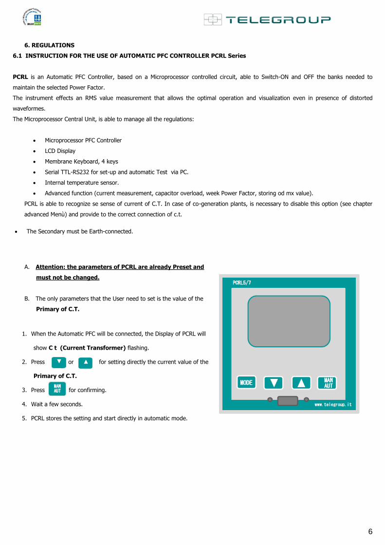
A. Attention: the parameters of PCRL are already Preset and
must not be changed.
B. The only parameters that the User need to set is the value of the
Primary of C.T.
1. When the Automatic PFC will be connected, the Display of PCRL will
show C t (Current Transformer) flashing.
2. Press or for setting directly the current value of the
Primary of C.T.
3. Press for confirming.
4. Wait a few seconds.
5. PCRL stores the setting and start directly in automatic mode.
▼ ▲

7
PCRL5/7.. Automatic Power Factor Controller INSTRUCTIONS MANUAL
● Before any maintenance operation on the device, remove all the voltages from measuring and supply inputs and short-circuit the CT
input terminals.
● Products illustrated herein are subject to alteration and changes without prior notice.
● Technical data and descriptions in the documentation are accurate, to the best of our knowledge, but no liabilities for errors,
omissions or contingencies arising there from are accepted.
● A circuit breaker must be included in the electrical installation of the building. It must be installed close by the equipment and within
easy reach of the operator.
It must be marked as the disconnecting device of the equipment:
IEC /EN 61010-1 § 6.11.2.1.
● Clean the instrument with a soft dry cloth; do not use abrasives, liquid detergents or solvents.
Index
Introduction Description Keyboard functions Display indications Operating modes Measures Keypad lock Expandability IR programming port Parameter setting through PC Parameter setting through tablets or Smarphones Setting of parameters (setup) from front panel Rapid CT setup Parameter table Alarms Alarm description Default alarm properties Command menu CX02 dongle usage Installation Wiring diagrams Terminal arrangement Mechanical dimensions and Panel cutout Technical carachteristics Manual revision history
Introduction The DCRL automatic power factor control unit has been designed to offer state-of-the-art functions for power factor compensation applications. Built with dedicated components and extremely compact, the DCRL combines the modern design of the front panel with practical installation and the possibility of expansion from the rear, where one EXP series module can be slotted. The LCD screen provides a clear and intuitive user interface.
WARNING!
Carefully read the manual before the installation or use. This equipment is to be installed by qualified personnel,
complying to current standards, to avoid damages or safety hazards.

8
Description Automatic power factor controller. Flush-mount, standard 96x96mm housing.
Backlit LCD screen. Versions:
o DCRL3 with 3 relays, expandable to 5 max. o DCRL5 with 5 relays, expandable to 7 max.
4 navigation keys for function and settings. Alarm messages in 6 languages. Expansion bus with 1 slot for EXP series expansion modules:
o RS232, RS485, USB communications interface. o Additional relay outputs.
High accuracy TRMS measurements. Wide selection of electrical measures, including voltage and current THD with harmonic analysis up to 15th order. Voltage input separated from power supply, suitable for VT connection in medium voltage applications. Wide-range power supply (100-440VAC). Front optical programming interface: galvanically isolated, high speed, waterproof, USB and WiFi dongle compatible. Programming from front panel, from PC or from tablet/smartphone. 2-level password protection for settings. Backup copy of original commissioning settings.
Built-in temperature sensor. Tool-less panel mount.
Front keyboard MODE Key - Used to select among available measurements. Used also to access programming menus. ▲ and ▼ keys - Used to set values and to select steps.
MAN-AUT key - Used to select operating mode between manual and automatic.
Display indications
Operating modes
There are three possible operating modes, listed below: TEST Mode When the unit is brand new and has never been programmed, it automatically enters in TEST mode that allows the installer to
manually activate the individual relay outputs, so you can verify the correct wiring of the panel. The TEST mode is indicated by three dashes --- shown on the main display.
The activation and deactivation of the outputs is done directly by pushing ▲and ▼buttons, but without considering the reconnection time.
The TEST mode is automatically left after the parameter programming is done (see Parameter setting chapter).
Output status Cooling fan
status
Secondary
display
Active alarm
Automatic mode
Manual
mode
Main display
Inductive /
capacitive
Bar graph
Alphanumeric display
Step status
Indication of TEST mode
Total number of steps
Firmware
revision
Model
variant

9
MAN and AUT Modes The icons AUT and MAN indicate the operating mode automatic or manual. To change the mode, press the MAN / AUT button for 1 sec in a row.
The operating mode remains stored even after removing and reapplying the power supply voltage. MAN Mode When the unit is in manual mode, you can select one of the steps and manually connected or disconnect it. In addition to the specific icon, the alphanumeric display shows MAN in order to highlight the manual mode condition. Press MODE
to view the other measurements as usual. While the display shows MAN, it is possible to select the step to be switched on or off. To select a step, use the ▲ or ▼buttons.
The selected step will flash quickly. Press MODE to activate or deactivate the selected step. If the selected step has not yet exhausted the reconnection time, the MAN icon will flash to indicate that the transaction has been
accepted and will be conducted as soon as possible.
Manual configuration of the steps is maintained even when the power supply voltage is removed. When the power returns, the original state of the steps is restored.
Select step Change step status
AUT Mode In automatic mode, the controller calculates the optimum configuration of capacitor steps in order to reach the set cos .
The selection criteria takes into account many variables such as: the power of each step, the number of operations, the total time of use, the reconnection time, etc.
The controller displays the imminent connection or disconnection of the steps with the flashing of their identification number (left). The flashing can last in cases in which the insertion of a step is not possible due to the reconnection time (discharge time of the capacitor).
The device initiates automatic corrections when there is an average reactive power request (delta-kvar) higher than 50% of the smallest step, and the measured cosphi is different from the setpoint.
Measures The DCRL provides a set of measurements displayed on the alphanumeric display, in conjunction with the current cosphi that is always
displayed on the main display. Press the MODE key to scroll through the measures in rotation. After 30 seconds without pressing any buttons, the display automatically returns to the default measurement defined by P.47. If P.47 is set on the ROT, then the measures rotate automatically every 5 seconds. At the bottom of the list of measures it is possible to set the setpoint of the cosphi, acting on the same value set with P.19. Below is a table with the measurements displayed.
Measure Icon Description
Delta-kvar Δkvar Kvars needed to reach the cosphi setpoint. If delta-kvar is positive cpacitors need to be inserted, if negative to be disconnected.
kvar Total kvar of the plant.
Δ STEP Number of equivalent steps.
Voltage V RMS voltage of the plant current.
V HI Maximum peak of measure.
Current A RMS current of the plant voltage.
A HI Maximum peak of measure.
▼
▲
▼
▼
MAN mode icon
Connected steps
Tot kvar inserited in
MAN
Manual step selection enabled
▼
MODE ▲
MODE
MODE

10
Weekly PF WPF Weekly average power factor.
PF Instantaneous total power factor.
Cap. current
%C.CU Calculated capacitor current, in % of their nominal.
%C.HI Maximum peak of measure.
Temperature °C °F Temperature of internal sensor.
°CHI °FHI
Maximum peak of measure.
Voltage
THD THDV Total harmonic distortion % (THD) of plant voltage.
VH02… ...VH15
% voltage harmonic content from 2.nd up to 15.th order
Current THD
THDI Total harmonic distortion % (THD) of plant current.
IH02… …IH15
% Current harmonic content from 2.nd up to 15.th order
Cosphi set point
IND CAP
Setting of desired cosphi setpoint (same as P.19).
Step power
% Step residual power, as a percentage of the set rated power.
Step counter
OPC
Operation counter of the step.
Step hours
H
Hour meter of the step insertion.
These measures are shown only if the Step trimming function is enabled (P.25=ON) and the advanced password is enabled and
entered. Keypad lock A function to exclude all modification to operating parameters can be enabled; measurement viewing is still provided in any case. To lock and unlock the keypad, press and keep MODE key pressed. Then press the ▲ key three times and the ▼key twice and after
that release MODE. The display will show LOC when the keypad is locked and UNL when it is unlocked. When the lock is enabled, it is not possible to make the following operations:
o Operation between automatic and manual mode o Access to set-up menus o Change of cosphi set-point
By attempting to conduct the above operations, the display will view LOC to indicate the locked keypad state.
▼
▼
▼
▼ ▲
▼ ▲
▼ ▲
MODE
MODE
MODE
MODE
MODE
MODE
▼ ▲
MODE
▼ ▲
MODE
▼ ▲
MODE

11
Parameter table
Below are listed all the programming parameters in tabular form. For each parameter are indicated the possible setting range and factory default, as well as a brief explanation of the function of the parameter. The description of the parameter shown on the display can in some cases be different from what is reported in the table because of the reduced number of characters available. The parameter code can be used however as a reference.
Note: the parameters shown in the table with a shaded background are essential to the operation of the system, thus they represent the minimum programming required for operation.
BASE MENU
COD DESCRIPTION ACC UoM DEF RANGE
P.01
CT primary
Usr A OFF OFF / 1...10.000
P.02
CT secondary
Usr A 5 1 / 5
P.03
CT read phase
Usr L3 L1
L2 L3
P.04
CT wiring polarity
Usr Aut Aut
Dir Inv
P.05
Voltage read phase Usr L2-L3 L1-L2 L2-L3 L3-L1 L1-N L2-N L3-N
P.06
Smallest step power
Usr Kvar … 0.10 ... 10000
P.07
Rated capacitor voltage Usr V …. 50 ... 50000
P.08
Nominal frequency
Usr Hz Aut Aut
50Hz 60Hz Var
P.09
Reconnection time
Adv sec 60 1 … 30000
P.10
Sensitivity
Usr sec 60 1 … 1000

12
P.11 Step 1 function
Usr ……. OFF
1…32
ON
NOA
NCA
FAN
MAN
AUT
A01…A13
P.12 Step 2 function
Usr
….
=
P.13 Step 3 function
Usr
…..
=
P.14 Step 4 function
Usr
……
=
P.15 Step 5 function
Usr
…..
=
P.16 Step 6 function
Usr
…..
=
P.17 Step 7 function
Usr
…..
=
P.19 Cos-phi setpoint
Usr
0.95 IND 0.50 Ind – 0.50 Cap
P.20 Alarm messages language
Usr
ENG ENG ITA FRA SPA POR DEU

13
P.01 - The value of the primary current transformer. Example: with CT 800/5 set 800. If set to OFF, after the power-up the device will prompt you to set the CT and allow direct access to this parameter. P.02 - Value of the secondary of the current transformers. Example: with CT 800/5 set 5.
P.03 – It defines on which phase the device reads the current signal. The wiring of current inputs must match the value set for this parameter. Supports all possible combinations of parameter P.05. P.04 - Reading the connection polarity of the CT. AUT = Polarity is automatically detected at power up. Can only be used when working with only one CT and when the system has no generator device. Dir = Automatic detection disabled. Direct connection. Inv = Automatic detection disabled. Reverse wiring (crossover). P.05 - Defines on which and on how many phases the device reads the voltage signal. The wiring of voltage inputs must match the setting for this parameter. Supports all possible combinations of parameter P.03. P.06 - Value in kvar of the smallest step installed (equivalent to the step weight 1). Rated power of the capacitor bank provided at the rated voltage specified in P.07 and referred to the total of the three capacitors for three-phase applications. P.07 - Rated plate capacitor, which is delivered in specified power P.06. If the capacitors are used to a voltage different (lower) than nominal, the resulting power is automatically recalculated by the device. P.08 - Working frequency of the system:
Aut = automatic selection between 50 and 60 Hz at power on. 50Hz = fixed to 50 Hz. 60Hz = fixed to 60 Hz.
Var = variable, measured continuously and adjusted. P.09 - Minimum time that must elapse between the disconnection of one step and the subsequent reconnection both in MAN or AUT mode. During this time the number of the step on the main page is blinking. P.10 - Connection sensitivity. This parameter sets the speed of reaction of the controller. With small values of P.10 the regulation is fast (more accurate around the setpoint but with more step swithchings). With high values instead we‟ll have slower reactions of the regulation, with fewer switchings of the steps. The delay time of the reaction is inversely proportional to the request of steps to reach the setpoint: waiting time = (sensitivity / number of steps required). Example: setting the sensitivity to 60s, if you request the insertion of one step of weight 1 are expected 60s (60/1 = 60). If instead serve a total of 4 steps will be expected 15s (60/4 = 15). P11 ... P18 - Function of output relays 1 ... 8:
OFF = Not used . 1 .. 32 = Weight of the step. This relay drives a bank of cpacitors which power is n times (n = 1…32) the smallest power defined with parameter P.06. ON = Always on. NOA = Alarm normally de-energized. The relay is energized when any alarm with the Global alarm property arises. NCA = Alarm normally energized. The relay is de-energized when any alarm with the Global alarm property arises. FAN = The relay controls the cooling fan. MAN = Relay is energized when device is in MAN mode. AUT = Relay is energized when device is in AUT mode. A01 ... A13 = The relay is energized when the alarm specified is active.
P.19 - Setpoint (target value) of the cosphi. Used for standard applications. P.20 - Language of scrolling alarm messages.

14
ADVANCED MENU
COD DESCRIPTION ACC UoM DEF RANGE
P.21
Password enable
Adv OFF OFF
ON
P.22
User password
Usr 001 0-999
P.23
Advanced password
Adv 002 0-999
P.24
Wiring type
Usr 3PH 3PH three-phase
1PH single-phase
P.25
Step trimming
Usr OFF ON Enabled
OFF Disabled
P.26
Setpoint clearance + Usr 0.00 0 – 0.10
P.27
Setpoint clearance - Usr 0.00 0 – 0.10
P.28
Step insertion mode
Usr STD STD Standard
Lin Linear
P.29
Cogeneration cos setpoint
Usr OFF OFF /
0.50 IND – 0.50 CAP
P.30
Disconnection sensitivity
Usr sec OFF OFF / 1 – 600
P.31
Step disconnection passing in MAN Usr
OFF OFF Disabled
ON Enabled
P.32
Capacitor current overload alarm threshold Adv %
125 OFF / 100...150
P.33
Capacitor overload immediate disconnection threshold
Adv %
150 OFF / 100.. 200
P.34
VT primary Usr V OFF OFF / 50-50000
P.35
VT secondary Usr V 100 50-500
P.36
Temperature UoM
Usr °C °C °Celsius
°F °Fahrenheit
P.37
Fan start temperature
Adv ° 35
0…212
P.38
Fan stop temperature
Adv ° 55 0…212
P.39
Temperature alarm threshold
Adv ° 50 0…212
P.40
Step failure alarm threshold Adv % OFF OFF / 25…100
P.41
Maximum voltage alarm threshold Adv % 120 OFF / 90...150

15
P.42
Minimum voltage alarm threshold Adv % OFF OFF / 60..110
P.43
THD V alarm threshold
Adv % OFF OFF / 1..250
P.44
THD I alarm threshold
Adv % OFF OFF / 1..250
P.45
Maintenance interval Adv h 9000 1 - 30000
P.46
Bar-graph function Usr Kvar ins/tot Kvar ins/tot Corr att/nom
Delta kvar att/tot
P.47
Default auxiliary measure Usr Delta kvar
Deltakvar V A
Week TPF Cap. Current
Temp THDV THDI ROT
P.48
Backlight flashing on alarm Usr OFF OFF ON
P.49
Serial node address Usr 01 01-255
P.50
Serial speed Usr bps 9.6k 1.2k 2.4k 4.8k 9.6k 19.2k 38.4k
P.51
Data format Usr 8 bit – n 8 bit, no parity 8 bit, odd 8bit, even
7 bit, odd 7 bit, even
P.52
Stop bits Usr 1 1-2
P.53
Protocol Usr Modbus RTU Modbus RTU Modbus ASCII
P.21 – If set to OFF, password management is disabled and anyone has access to the settings and commands menu. P.22 – With P.21 enabled, this is the value to specify for activating user level access. See Password access chapter.
P.23 – As for P.22, with reference to Advanced level access P.24 – Number of phases of the power correction panel. P.25 - Enables the measurement of the actual power of the step, performed each time they are switched in. The measure is calculated, as the current measurement is referred to the whole load of the plant. The measured power of the steps is adjusted (trimmed) after each switching and is displayed on the step life statistic page. When this function is enabled, a 15 sec pause is inserted between the switching of one step and the following, necessary to measure the reactive power variation. P.26 – P.27 - Tolerance around the setpoint. When the cosphi is within the range delimited by these parameters, in AUT mode the device does not connect / disconnect steps even if the delta-kvar is greater than the smallest step. Note: + means „towards inductive‟, while – means „towards capacitive‟.

16
P.28 - Selecting mode of steps insertion. Standard mode - Normal operation with free selection of the steps Linear mode - the steps are connected in progression from left towards right only following the step number and according to
the LIFO (Last In First Out) logic. The controller will not connect a step when the system steps are of different ratings and by connecting the next step, the set-point value would be exceeded.
P.29 - Setpoint used when the system is generating active power to the supplier (with negative active power / power factor ). P.30 - Disconnection sensitivity. Same as the previous parameter but related to disconnection. If set to OFF the disconnection has the same reaction time of connection set with the previous parameter. P.31 - If set to ON, when switching from AUT mode to MAN mode, steps are disconnected in sequence. P.32 – Trip threshold for the capacitors overload protection (alarm A08), that will arise after a integral delay time, inversely proportional to the value of the overload. Note: You can use this protection only if the capacitors are not equipped with filtering devices such as inductors or similar. P.33 - Threshold beyond which the integral delay for tripping of the overload alarm is zeroed, causing the immediate intervention of the A08 alarm. P.34 – P.35 – Data of VTs eventually used in the wiring diagrams. P.36 – Unit of measure for temperature. P.37 – P.38 - Start and stop temperature for the cooling fan of the panel, expressed in the unit set by P.36. The cooling fan is started when the temperature is >= to P.37 and it is stopped when it is < than P.38. P.39 - Threshold for generation of alarm A08 Panel temperature too high . P.40 - Percentage threshold of the residual power of the steps, compared with the original power programmed in general menu. Below this threshold the alarm A10 step failure is generated. P.41 - Maximum voltage alarm threshold, referred to the rated voltage set with P.07, beyond which the alarm A06 Voltage too high is generated. P.42 - Undervoltage alarm threshold, referred to the rated voltage set with P.07, below which the alarm A05 voltage too low is generated. P.43 - Maximum plant voltage THD alarm threshold, beyond which the alarm A10 THDV too high is generated. P.44 – Maximum plant current THD alarm threshold beyond which the alarm A05 voltage too low is generated. P.45 – Maintenace interval in hours. When it is elapsed, the alarm A12 maintenance interval will be generated. The hour count increments as long as the device is powered. P.46 – Function of the semi-circular bar-graph.
Kvar ins/tot: The bar graph represents the amount of kvar actually inserted, with reference to the total reactive power installed in the panel. Curr act/nom: Percentage of actual plant current with reference to the maximum current of the CT. Delta kvar: bar graph with central zero. It represts the positive/negative delta-kvar needed to reach the setpoint, compared to the total kvar installed.
P.47 – Default measure shown on the secondary display. Setting the parameter to ROT, the different measures will be shown with a
sequential rotation. P.48 – If set to ON, the display backlight flashes in presence of one or more active alarms. P.49 – Serial (node) address of the communication protocol. P.50 – Communication port transmission speed. P.51 – Data format. 7 bit settings can only be used for ASCII protocol. P.52 – Stop bit number. P.53 – Select communication protocol.

17
Alarms
When an alarm is generated , the display will show an alarm icon, the code and the description of the alarm in the language selected. If the navigation keys in the pages are pressed, the scrolling message showing the alarm indications will disappear momentarily, to
reappear again after 30 seconds. Alarms are automatically resetted as soon as the alarm conditions that have generated them disappear. In the case of one or more alarms, the behaviour of the DCRL depends on the properties settings of the active alarms.
Alarm description
ALARM DESCRIPTION
A01 Undercompensation In automatic mode, all the available steps are connected but the cosphi is
still more inductive than the setpoint.
A02 Overcompensation In automatic mode, all the steps are disconnected but the cosphi is still
more capacitive than the setpoint.
A03 Current too low The current flowing in the current inputs is lower than minimum measuring
range.
This condition can occour normally if the plant has no load.
A04 Current too high The current flowing in the current inputs is lower than minimum measuring
range.
A05 Voltage too low The measured voltage is lower than the threshold set with P.42.
A06 Voltage too high The measured voltage is higher than the threshold set with P.41.
A07 Capacitor current overload The calculated capacitor current overload is higher than threshold set with
P.32 and P.33. After the alarm conditions have disappeared, the alarm
message remains shown for the following 5 min or until the user presses a
key on the front.
A08 Temperature too high The panel temperature is higher than threshold set with P.39.
A09 No-Voltage release A no-voltage release has occoured on the line voltage inputs, lasting more
than 8ms.
A10 Voltage THD too high
The THD of the plant voltage is higher than the threshold set with P.43.
A11 Current THD too high The THD of the plant current is higher than the threshold set with P.44.
A12 Maintenance requested The maintenance interval set with P.45 has elapsed. To reset the alarm
use the command C.01 (see Command menu).
A13 Step failure The residual power of one or more steps is lower than minimum threshold
set with P.40.

18

19
20

21

22
TELEGROUP S.r.l. Via L. Da Vinci, 100, 50028, Tavarnelle Val di Pesa – Loc. Sambuca – FIRENZE - ITALY – Phone +39
055 80 71 267 /118 Fax. + 39 055 80 71 338 www.telegroup.it