Uses of the Slit Lamp - chicago.medicine.uic.edu · I• ! 216 Ch ptcr 10: Slit-Lamp Biomicroscopy...
16
2 14 Chapter I 0: Slit-Lamp Biomicroscopy for perrming Goldmann applanation tonometry with the slit lamp appear in Chapter 12; instructions r indirect slit-lamp biomicroscopy of the posterior segment are included in Chapter 13. Uses of the Slit Lamp The slit lamp is indispensable r the detailed examination of virtually all tissues of the eye and some of its adnexa. It is routinely used for examination of the anterior segment, which includes the anterior vit- reous and those structures that are anterior to it. Most of the anterio1 segment tissues (except the anterior chamber angle and the posterior surce of the iris) are directly visible witl1 the slit lamp alone, witl1our special variations in technique or nonstandard attachments or lenses. Optical consn·aints of tl1e instrument and the eye to be examined pre- vent useful visualization of the angle of tl1e anterior chamber and tl1ose structures that are posterior to the anterior vitreous unless various attachments or accessories are used (as discussed later in this chapter and in Chapters 11 and J 3). In addition to physical (visual) examination, tl1e slit lamp is often used r tonomeay, linear measurement of tissues or lesions, and oph- thalmic photography. ft can also be used in contact lens fitting, although this topic is beyond tl1e scope of this manual. Parts of the Slit Lamp A typical slit lamp is illusn-ated in Figure l0.1. The Haag-Streit 900 model is shown because it is the most commonly encountered; several other fine slit lamps arc available whose differences from the Haag- Sa·eit instrument arc usually relatively minor or are easily mastered. The slit-lamp biomicroscope consists of three principal portions: the viewing arm, containing the eyepiece and magnifying elements; the illumination arm, containing the light source and many of its con- trols; and tl1c patient-positioning f r ame. These portions are connect- ed to a base, which has a joystick that the examiner uses to move the viewing and illumination arms about. The entire unit is wired lO :1 transformer power source on a supporting platrm. The specific p:ms of tl1e insa·ument are detailed below ; numbers in parentheses corre- spond to the numbers in Figure 10. l.
-
Upload
truongduong -
Category
Documents
-
view
228 -
download
0
Transcript of Uses of the Slit Lamp - chicago.medicine.uic.edu · I• ! 216 Ch ptcr 10: Slit-Lamp Biomicroscopy...
2 14 Chapter I 0: Slit-Lamp Biomicroscopy
for performing Goldmann applanation tonometry with the slit lamp
appear in Chapter 12; instructions for indirect slit-lamp biomicroscopy
of the posterior segment are included in Chapter 13.
Uses of the Slit Lamp
The slit lamp is indispensable for the detailed examination of virtually all tissues of the eye and some of its adnexa. It is routinely used for examination of the anterior segment, which includes the anterior vitreous and those structures that are anterior to it. Most of the anterio1 segment tissues (except the anterior chamber angle and the posterior surface of the iris) are directly visible witl1 the slit lamp alone, witl1our special variations in technique or nonstandard attachments or lenses. Optical consn·aints of tl1e instrument and the eye to be examined prevent useful visualization of the angle of tl1e anterior chamber and tl1ose structures that are posterior to the anterior vitreous unless various attachments or accessories are used (as discussed later in this chapter and in Chapters 11 and J 3).
In addition to physical (visual) examination, tl1e slit lamp is often used for tonomeay, linear measurement of tissues or lesions, and ophthalmic photography. ft can also be used in contact lens fitting, although this topic is beyond tl1e scope of this manual.
Parts of the Slit Lamp
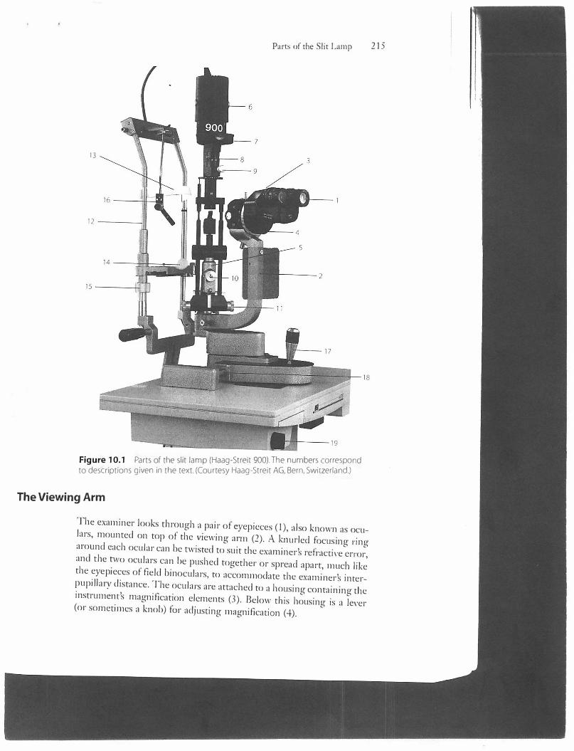
A typical slit lamp is illusn-ated in Figure l 0.1. The Haag-Streit 900 model is shown because it is the most commonly encountered; several other fine slit lamps arc available whose differences from the HaagSa·eit instrument arc usually relatively minor or are easily mastered.
The slit-lamp biomicroscope consists of three principal portions: the viewing arm, containing the eyepiece and magnifying elements; the illumination arm, containing the light source and many of its controls; and tl1c patient-positioning frame. These portions are connected to a base, which has a joystick that the examiner uses to move the viewing and illumination arms about. The entire unit is wired lO :1 transformer power source on a supporting platform. The specific p:ms of tl1e insa·ument are detailed below; numbers in parentheses correspond to the numbers in Figure 10. l.
13
Parts of the Slit Lamp 215
Figure 10.1 Parts of the slit lamp (Haag-Streit 900). The numbers correspond to descriptions given in the text. (Courtesy Haag-Streit AG, Bern, Switzerland.)
The Viewing Arm
The examiner looks through a pair of eyepieces (I), also known as oculars, mounted on top of the viewing arm (2). A knurled focusing ringaround each ocular can be twisted to suit the examiners refractive error,and the two oculars can be pushed together or spread apart, much likethe eyepieces of field binoculars, to accommodate the examiners interpupillary distance. The oculars are attached to a housing containing theinstrument's magnification elements (3). Below tl1is housing is a lever(or sometimes a knob) for adjusting magnification (4).
I• !
216 Ch�ptcr 10: Slit-Lamp Biomicroscopy
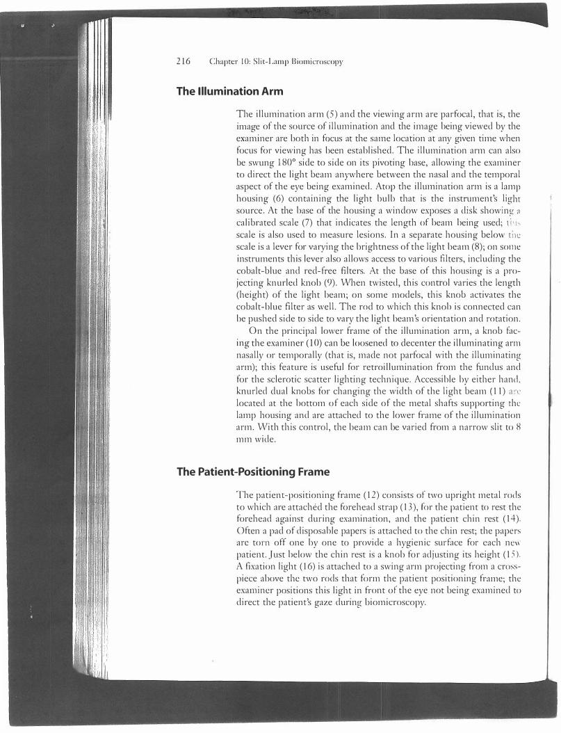
The Illumination Arm
The illumination arm (5) and the viewing arm are parfocal, that is, the image of the source of illumination and the image being viewed by the examiner are both in focus at the same location at any given time when focus for viewing has been established. The illumination arm can also be swung 180° side co side on its pivoting base, allowing the examiner to direct the light beam anywhere between the nasal and the temporal aspect of the eye being examined. Atop the illumination arm is a lamp housing (6) containing the light bulb that is the instrument's light source. At the base of the housing a window exposes a disk showing :1
calibrated scale (7) that indicates the length of beam being used; ti h
scale is also used to measure lesions. In a separate housing below ti1c scale is a lever for varying the brightness of the light beam (8); on some instruments this lever also allows access to various filters, including the cobalt-blue and red-free filters. At the base of this housing is a projecting knurled knob (9). When twisted, this conu·ol varies the length (height) of the light beam; on some models, this knob activates the cobalt-blue filter as well. The rod to which this knob is connected can be pushed side to side to vary the light beam's orientation and rotation.
On the principal lower frame of the illumination arm, a knob facing the examiner (10) can be loosened to decenter the illuminating arm nasally or temporally (that is, made not parfocal with the illuminating arm); this feature is useful for retroillumination from the fundus and for the sclerotic scatter lighting technique. Accessible by either hand. knurled dual knobs for changing the width of the light beam (11) a,.L' located at the bottom of each side of the metal shafts supporting the lamp housing and are attached to the lower frame of the illumination arm. With this control, the beam can be varied from a narrow slit to 8 mm wide.
The Patient-Positioning Frame
The patient-positioning frame ( 12) consists of two upright metal rods to which are attached the forehead strap (13), for the patient to rest the forehead against during examination, and the patient chin rest (I-+). Often a pad of disposable papers is attached to the chin rest; the papers arc torn off one by one to provide a hygienic surface for each nc\1 patient . .Just below the chin rest is a knob for adjusting its height (15). A fixation light (16) is attached to a swing arm projecting from a crosspiece above the two rods that form the patient positioning frame; the examiner positions this light in front of the eye not being examined to direct the patient's gaze during biomicroscopy.
The Base
Preparing and Positioning the Pnicnt 217
The slit lamp's joystick control (17) is located on the base of the instrument within easy reach of the examiner who is looking through the oculars. The joystick is used to shift the viewing and illumination arms forward, backward, laterally, or diagonally. On some instruments, the joystick is twisted and rotated to lower and elevate the light beam. A locking knob ( 18) in the base near the common support of the viewing and illumination arms can be loosened to allow the insa·ument's body to be shifted toward the patient to grossly position it at the beginning of an examination; the knob is tightened to prevent the slit lamp from shifting when it is not in use. Under the instrument supporting platform is a knob for turning the slit lamp's power transformer on and off (19); it usually also has three settings for degrees of brightness, although the lowest (5 V) is the most commonly used.
Other Attachments
Various additional devices can be attached to the slit lamp, such as an applanation tonometer for measuring intraocular pressure and a Hruby lens for examining the fundus. These are not shown in Figure I 0.1 but they are discussed later in this chapter, and instructions for their use are provided in Chapters 12 and 13, respectively.
Preparing and Positioning the Patient
The patient's head is positioned and steadied for slit-lamp examination by means of a chin rest and a forehead strap. The chin rest usually consists of a concave plastic cup to which is attached a stack of disposable tissue papers. The tissue on which the last patient's chin rested is torn away to expose a fresh tissue for the patient to be examined, preferably in view of the patient so that he or she knows that a clean chin rest is being provided. The chin rest occasionally consists only of the plastic cup, without the tissues; in this situation patients often appreciate seeing the physician clean the cup with a wipe of an alcohol swab or tissue. Rarely, patients want to see the forehead sn·ap cleaned.
With the patient's forehead and chin firmly in place, the height of the chin rest can be raised or lowered by means of a nearby knob; in this way, the patient's eye is brought level with the black demarcation line on one of the supporting rods of the patient-positioning frame just below the level of the forehead strap.
218 Chapter 10: Slit-Lamp Biomicroscopy
The patient's chin should be well seated in the chin rest and the forehead pressed firmly against the forehead strap. Some patients tend to drift backward and might need to be helped, or encouraged, by the examiner or an assistant to keep the forehead forward. The slit lamp's viewing and illumination portions should be well back from the chin rest and forehead strap before attempting to position the patient; otherwise, the patient's nose, or even eye, can be bumped by slit-lamp apparan1s.
It can be difficult to position the slit lamp and its headrest close to obese patients, because their upper bodies tend to push everything away. Such patients can be accommodated by keeping the slit lamp farther away, requiring them to lean forward and to extend their neck· ''> some degree.
Patients who have relatively short torsos often cannot be set well into the headrest because the table on which the instrument is mounted applies uncomfortable pressure to their thighs or knees. In such cases it can be useful either again to have the patient lean forward more or to fold up the footrest on the patient's chair so that the patient's legs can be dangled (providing more room above the thighs and knees). You might instead ask the patient to t\vist to one side (or rotate the patient's chair away from the angle of approach of the slit lamp) to enable you to bring the slit lamp in from an angle (instead of from straight ahead) and to have the patient's legs to the side of the slit-lamp table.
Be sure to adjust the settings on the slit lamp so that the patient is not initially subje::ted to uncomfortably bright light when the instrument is turned on. This can be accomplished by setting the instrument to provide a very narrow beam of light, or by providing illuminatirn1 that is filtered by the cobalt-blue or red-free (green) filter, or by dimming the light source if it is set to provide diffuse illumination.
It is always considerate to ask if the patient is comfortable before beginning the examination. The stool on which the examiner sits should be adjusted to a comfortable height, and the slit lamp's oculars should be adjusted for the examiner's interpupillary distance.
Principles of Slit-Lamp Illumination
The slit lamp is capable of illuminating the tissues of the eye in several different ways, any or all of which can be useful, depending on the clinical situation. The beginning ophthalmology resident should strive early to master all of these techniques of illumination, so as to be able to use the slit lamp to its full advantage.
The slit lamp offers six main illuminating options, each with its own special properties and particular uses:
Principles of Slit-Lamp Illumination 219
1. Diffuse illumination
2. Direct focal illumination
3. Specular reflection
4. Transillumination, or retroillumination
5. Indirect lateral illumination
6. Sclerotic scatter
In addition, moving the slit beam by oscillating it allows the examiner to observe properties of certain ocular tissues that cannot be viewed with static lighting alone. All of these illumination techniques are described in detail below.
Diffuse Illumination
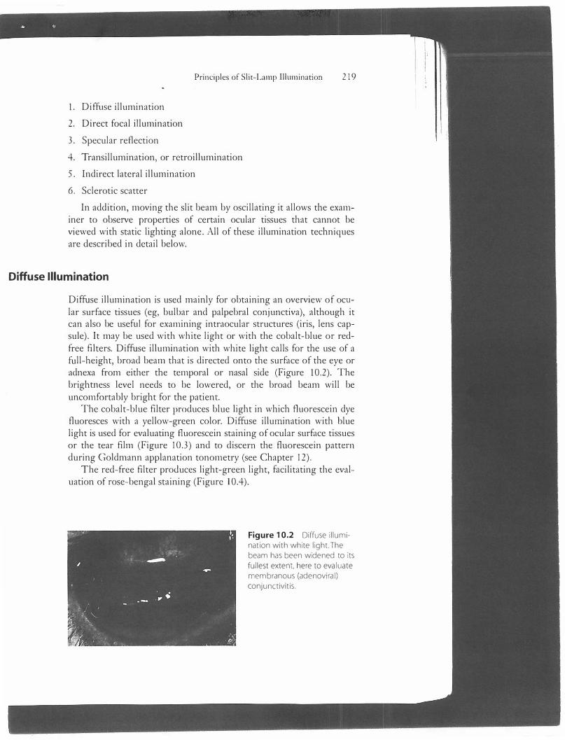
Diffuse illumination is used mainly for obtaining an overview of ocular surface tissues (eg, bulbar and palpebral conjunctiva), although it can also be useful for examining intraocular structures (iris, lens capsule). It may be used with white light or with the cobalt-blue or redfree filters. Diffuse illumination with white light calls for the use of a full-height, broad beam that is directed onto the surface of the eye or adnexa from either the temporal or nasal side (Figure 10.2). The brightness level needs to be lowered, or the broad beam will be uncomfortably bright for the patient.
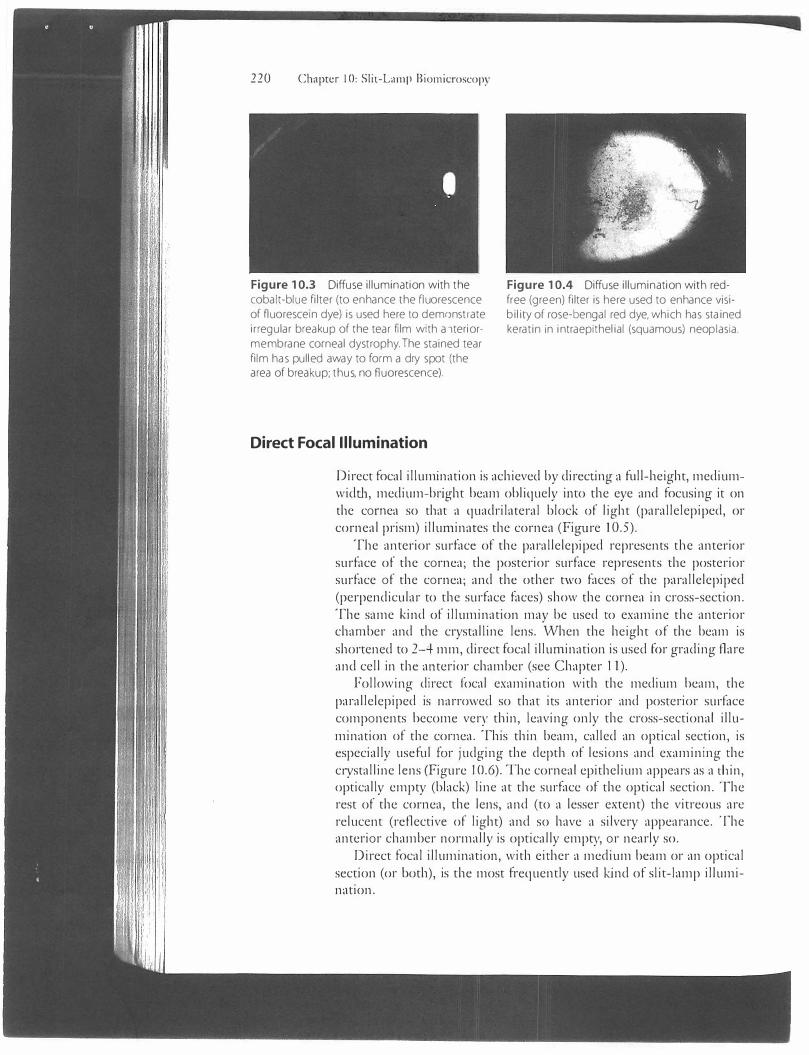
The cobalt-blue filter produces blue light in which fluorescein dye fluoresces with a yellow-green color. Diffuse illumination with blue light is used for evaluating f1uorescein staining of ocular surface tissues or the tear film (Figure 10.3) and to discern the fluorescein pattern during Goldmann applanation tonometry (see Chapter 12).
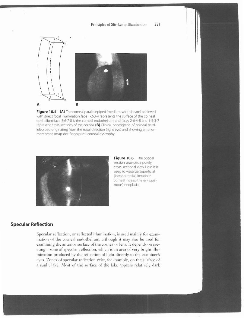
T he red-free filter produces light-green light, facilitating the evaluation of rose-bengal staining (Figure 10.4).
Figure 10.2 Diffuse illumination with white light.The beam has been widened to its
fullest extent, here to evaluate membranous (adenoviral)
conjunctivitis.
I ;
220 Chapter I 0: Slil-Lamp Biomicroscopy
Figure 10.3 Diffuse illumination with the cobalt-blue filter (to enhance the nuorescence of fluorescein dye) is used here to dem()nstrate ir regular breakup of the tear film with a ,teriormembrane corneal dystrophy. The stained tear film has pulled away to form a dry spot (the area of breakup; thus, no fluorescence).
Direct Focal Illumination
Figure 10.4 Diffuse illumination with redfree (green) filter is here used to enhance visibility of rose-bengal red dye, which has stained keratin in intraepithelial (squamous) neop lasia.
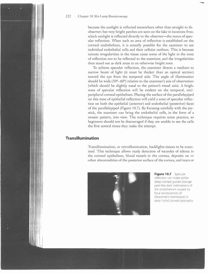
Direct focal illum.ination is achieved by directing a full-height, mediumwidth, medium-bright beam obliquely into the eye and focusing it on the cornea so that a quadrilateral block of light (parallelepiped, or corneal prism) illumin,nes the cornea (Figure l 0.5).
The anterior surface of the parallelepiped represents the anterior surface of the cornea; the posterior surface represents the posterior surface of the cornea; and the other two faces of the parallelepiped (perpendicular to the surface faces) show the cornea in cross-section. The same k.ind of illumination may be used to examine the anterior chamber and the crystalline lens. When the height of the beam is shortened to 2-4 mm, direct focal illumination is used for grading flare and cell in the anterior chamber (see Chapter 11).
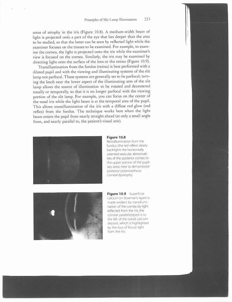
Following direct focal examim1tion with the medium beam, the parallelepiped is narrowed so that its anterior and posterior surface components become very thin, leaving only the cross-sectional illumination of the cornea. This thin beam, called an optical section, is especially useful for judging the depth of lesions and examining the c1ystalline lens (Figure 10.6). The corneal epithelium appears as a thin, optically empty (black) line at the surface of the optical section. The rest of the cornea, the lens, and (to a lesser extent) the vitreous arc relucent (reflective of light) and so have a silvery appearance. The anterior chamber normally is optically empty, or nearly so.
Direct focal illumination, with either a medium beam or an optical section (or both), is the most frequently used k.ind of slit-lamp illumination.
A B
Principles of Slit-Lamp lllumination 221
Figure 10.5 (A) The corneal parallelepiped (medium-width beam) achieved
with direct focal illumination; face 1-2-3-4 represents the surface of the corneal epithelium; face 5-6-7-8 is the corneal endothelium; and faces 2-6-4-8 and 1-5-3-7 represent cross-sections of the cornea. (B) Clinical photograph of corneal paral
lelepiped originating from the nasal direction (right eye) and showing anteriormembrane (map-dot-fingerprint) corneal dystrophy.
Specular Reflection
Figure 10.6 The optical section provides a purely cross-sectional view. Here it is used to visualize superficial (intraepithelial) keratin in corneal intraepithelial (squamous) neoplasia.
Specular reflection, or reflected illumination, is used mainly for examination of the corneal endothelium, although it may also be used for examining the anterior surface of the cornea or lens. It depends on creating a zone of specular reflection, which is an area of very bright illumination produced by the reflection of light directly to the examiner's eyes. Zones of specular reflection exist, for example, on the surface of a sunlit lake. Most of the surface of the lake appears relatively dark
222 Chapter I 0: Slit-Lamp Biomicroscopy
because the sunlight is reflected somewhere other than straight to th, observer; but ve1y bright patches are seen on the lake in locations from which sunlight is reflected directly to the observer-the zones of specular reflection. \Vhen such an area of reflection is established on the corneal endothelium, it is actually possible for the examiner to see individual endothelial cells and tl1eir cellular outlines. This is because minute irregularities in the tissue cause some of the light in the zone of reflection not to be reflected to the examiner, and tl1e irregularities then stand out as dark areas in an otherwise bright zone.
To achieve specular reflection, the examiner directs a medium to narrow beam of light (it must be tl1icker than an optical section) toward the eye from tl1e temporal side. The angle of illumination should be wide (50°-60°) relative to tl1e examiner's axis of observation (which should be slightly nasal to the patient's visual axis). A brigh1 zone of specular reflection will be evident on the temporal, midperipheral corneal epithelium. Placing the surface of the parallelepiped on tl1is zone of epitl1elial reflection will yield a zone of specular reflection on both the epithelial (anterior) and endothelial (posterior) faces of the parallelepiped (Figure 10.7). By focusing carefully witl, the joystick, the examiner can bring the endothelial cells, in the form of a mosaic pattern, into view. The technique requires some practice, so beginners should not be discouraged if they are unable to see the cells tl1e first several times they make the attempt.
Transillumination
Transillumination, or retroillumination, backlights tissues to be examined. T his technique allows ready detection of vacuoles of edema in the corneal epitl1elium, blood vessels in the cornea, deposits on or other abnormalities of the posterior surface of the cornea, and tears or
Figure 10.7 Specular reflection can make visible deep corneal guttae (orangepeel-like, dark indentations of the endothelium caused by focal excrescences of Descemet's membrane) in early Fuchs' corneal dystrophy.
-
Principles of Slit-Lamp Illumination 22 3
areas of atrophy in the iris (Figure 10.8). A medium-width beam of light is projected onto a part of the eye that lies deeper than the area to be studied, so that the latter can be seen by reflected light while the examiner focuses on the tissues to be examined. For example, to examine the cornea, the light is projected onto the iris while the examiner's view is focused on the cornea. Similarly, the iris may be examined by directing light onto the surface of the lens or the retina (Figure 10.9).
Transillumination from the funclus (retina) is best performed with a dilated pupil and with the viewing and illuminating systems of the slit lamp not parfocal. These systems are generally set to be parfocal; n1rning the knob near the lower aspect of the illuminating arm of the slit lamp allows the source of illumination to be rotated and decentered nasally or temporally, so that it is no longer parfocal with the viewing portion of the slit lamp. For example, you can focus on the center of the nasal iris while the light beam is at the temporal area of the pupil. T his allows o·ansillumination of the iris with a diffuse red glow (red reflex) from the fundus. The technique works best when the light beam enters the pupil from nearly straight ahead (at only a small angle from, and nearly parallel to, the patient's visual ax.is).
Figure 10.8 Retroillumination from the fundus (the red reflex) clearly backlights the horizontally oriented vesicular abnormali· ties of the posterior cornea (in the upper portion of the pupil· lary area), here to demonstrate posterior polymorphous corneal dystrophy.
Figure 10.9 Superficial calcium (in Bowman's layer) is made evident by transillumination of the cornea by light reflected from the iris; the corneal parallelepiped is to the left of the ovoid calcium deposit, which is highlighted by the (out of focus) light from the iris.
224 Chapter I 0: Slit-Lamp Biomicroscopy
Indirect Lateral Illumination
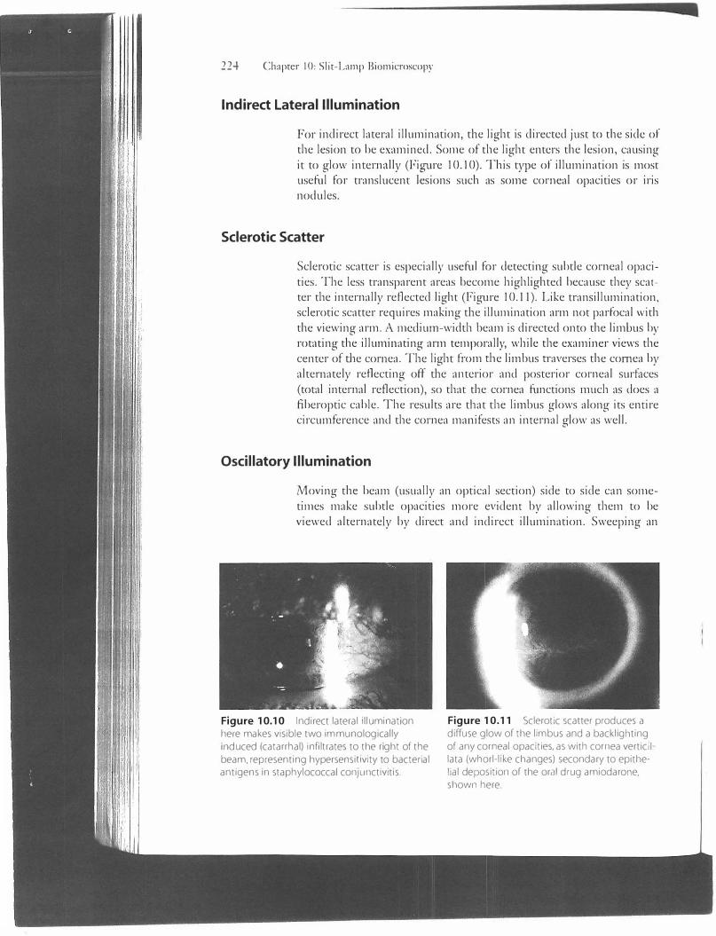
For indirect lateral illumination, the light is directed just co the side of the lesion to be examined. Some of the light enters the lesion, causing it to glow internally (Figure I 0.10). This type of illumination is most useful for translucent lesions such as some corneal opacities or iris nodules.
Sclerotic Scatter
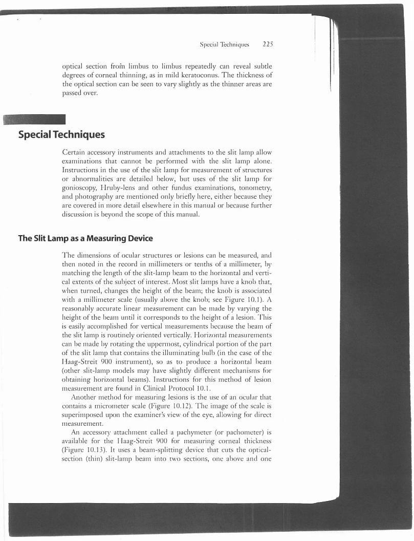
Sclerotic scatter is especially useful for detecting subtle corneal opacities. The less transparent areas become highlighted because they scatter the internally reflected light (Figure I 0.11). Like transillumination, sclerotic scatter requires making the illumination arm not parfocal with the viewing arm. A medium-width beam is directed onto the limbus by rotating the illumirniting arm temporally, while tl1e examiner views the center of the cornea. The light from the limbus o·averses the cornea by alternately reflecting off the anterior and posterior corneal surfaces (total internal reflection), so that tl,e cornea functions much as does a fiberoptic cable. The results arc tl1at tl1e lirnbus glows along its entire circumference and the cornea manifests an internal glow as well.
Oscillatory Illumination
Moving the beam (usually an optical section) side co side can sometimes make subtle opacities more evident by allowing them co be viewed alternately by direct and indirect illumination. Sweeping an
Figure 10.10 Indirect lateral illumination here makes visible two immunologically induced (catarrhal) infiltrates to the right of the beam. representing hypersensiuvity to bacterial antigens 1n staphylococcal conJunctivitis.
Figure 10.11 Sclerotic scatter produces a diffuse glow of the limbus and a backl1ghting of any corneal opacities. as with cornea vertic1I lata (whorl-like changes) secondary to epithelial deposition of the oral drug amiodarone. shown here.
Special Techniques 2 2 5
optical section from limbus to limbus repeatedly can reveal subtle degrees of corneal thinning, as in mild keratoconus. The thickness of the optical section can be seen to vary slightly as tl1e thurner areas are passed over.
Special Techniques
Certain accessory inso·uments and attachments to tl1e slit lamp allow examinations that cannot be performed with tl1e slit lamp alone. Instructions in the use of the slit lamp for measurement of strucnires or abnormalities are detailed below, but uses of the slit lamp for gonioscopy, Hruby-lens and other fundus examinations, tonometi·y, and photography are mentioned only briefly here, eitl1er because they arc covered in more detail elsewhere in this manual or because furtl1er discussion is beyond tl1e scope of tl1is manual.
The Slit Lamp as a Measuring Device
The dimensions of ocular structures or lesions can be measured, and then noted in the record in millimeters or tenths of a millimeter, by matching the lengtl1 of the slit-lamp beam co the horizontal and vertical extents of tl1e subject of interest. Most slit lamps have a knob that, when turned, changes the height of the beam; the knob is associated witl1 a millimeter scale (usually above the knob; see figure JO.I). A reasonably accurate linear measurement can be made by va1·ying the height of the beam until it corresponds to tl1e height of a lesion. This is easily accomplished for vertical measurements because tl1e beam of the slit lamp is routinely oriented vertically. Horizontal measurements can be made by rotating the uppermost, cylindrical portion of the part of me slit lamp that contains the illuminating bulb (in the case of the Haag-Streit 900 insti·ument), so as to produce a horizontal beam (other slit-lamp models may have slightly different mechanisms for obtaining horizontal beams). lnso·uctions for mis method of lesion measurement are found in Clinical Protocol 10.1.
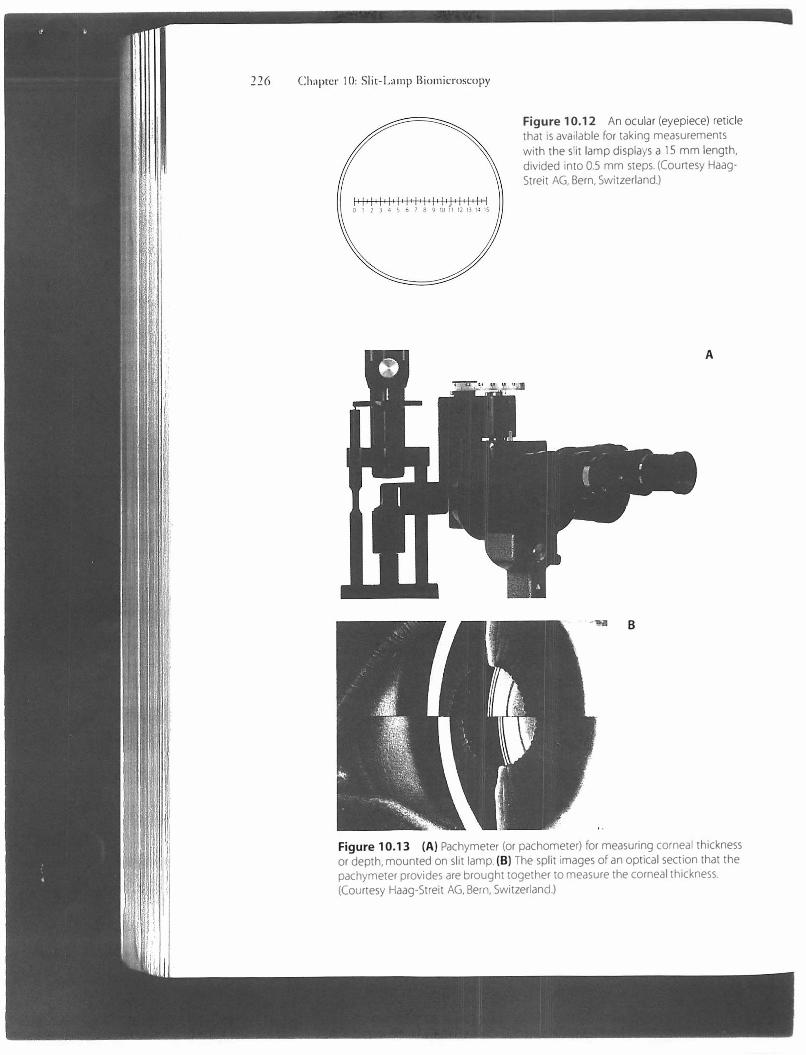
Anotl1er metl1od for measuring lesions is the use of an ocuh1r that contains a micrometer scale (figure 10.12). The image of the scale is superimposed upon me examiner's view of the eye, allowing for direct measurement.
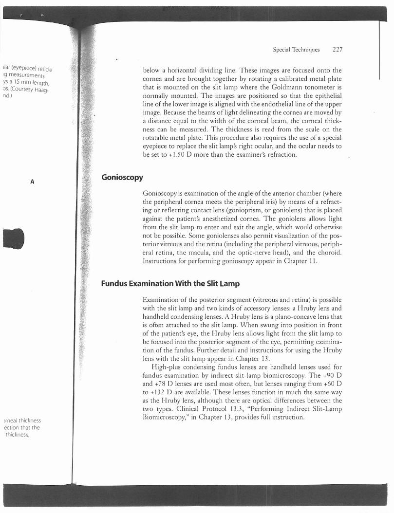
An accessory attachment called a pachymeter (or pachometer) is available for the Haag-Streit 900 for measuring corneal tl1ickness (figure 10.13). Jc uses a beam-splitting device that cuts the opticalsection (tl1in) slit-lamp beam into two sections, one above and one
226 Chapter I 0: Slit-Lamp Biomicroscopy
Figure 10.12 An ocular (eyepiece) reticle that is available for taking measurements
with the slit lamp displays a 15 mm length, divided into 0.5 mm steps. (Courtesy HaagStreit AG, Bern, Switzerland.)
A
B
Figure 10.13 (A) Pachymeter (or pachometer) for measuring corneal thickness or depth, mounted on slit lamp. (Bl The split images of an optical section that the pachymeter provides are brought together to measure the corneal thickness. (Courtesy Haag-Streit AG, Bern, Switzerland.)
liar (eyepiece) reticle9 measurementsys a 15 mm length,os. (Courtesy Haagnd.)
A
)rneal thickness ection that the thickness.
Special Techniques 22 7
below a horizontal dividing line. These images are focused onto the cornea and are brought together by rotating a calibrated metal plate that is mounted on the slit lamp where the Goldmann tonometer is normally mounted. The images are positioned so that the epithelial line of the lower image is aligned with the endothelial line of the upper image. Because the beams of light delineating the cornea are moved by a distance equal to the width of the corneal beam, the corneal thickness can be measured. The thickness is read from the scale on the rotatable metal plate. This procedure also requires the use of a special eyepiece to replace the slit lamp's right ocular, and the ocular needs to be set to +l.50 D more than the examiner's refraction.
Gonioscopy
Gonioscopy is examination of the angle of the anterior chamber (where the peripheral cornea meets the peripheral iris) by means of a refracting or reflecting contact lens (gonioprism, or goniolens) that is placed against the patient's anesthetized cornea. The goniolens allows light from the slit lamp to enter and exit the angle, which would otherwise not be possible. Some goniolenses also permit visualization of the posterior vitreous and the retina (including the peripheral vitreous, peripheral retina, the macula, and the optic-nerve head), and the choroid. Instructions for performing gonioscopy appear in Chapter 11.
Fundus Examination With the Slit Lamp
Examination of the posterior segment (vitreous and retina) is possible with the slit lamp and two kinds of accessory lenses: a Hruby lens and hand held condensing lenses. A Hruby lens is a piano-concave lens that is often attached to the slit lamp. Vvhen swung into position in front of the patient's eye, the Hruby lens allows light from the slit lamp to be focused into the posterior segment of the eye, permitting examination of the fund us. Further detail and instructions for using the Hruby lens with the slit lamp appear in Chapter 13.
High-plus condensing fundus lenses are handheld lenses used for fundus examination by indirect slit-lamp biomicroscopy. The +90 D and + 78 D lenses are used most often, but lenses ranging from +60 D to +132 Dare available. These lenses function in much the same way as the Hruby lens, although there are optical differences between the two types. Clinical Protocol 13.3, "Performing Indirect Slit-Lamp Biomicroscopy," in Chapter 13, provides full instruction.
228 Chapter IO: Slit-Lamp Biomicroscopy
Goldmann Tonometry
A Goldmann tonometer attached to the slit lamp is used to measure intraocular pressure. The procedure requires the use of fluorescein dye and the slit lamp's cobalt-blue filter. Clinical Protocol 12.1, "Performing Goldma1111 Applanation Tonometry," in Chapter 12, provides instructions.
Slit-Lamp Photography
Some slit lamps have 3 5 mm still cameras attached, permitting the taking of clinical photographs. The use of two such cameras on a slit lamp makes stereoscopic photography possible. Sometimes a video camera is connected to the slit lamp.
Pitfalls and Pointers
.... . ..
• Remember to set the oculars to your refractive error, or to pianoif you use the slit lamp while wearing your glasses; otherwise it can be difficult to obtain a clearly focused view.
• Difficulties occur if the patient is not made reasonably comfortable just prior to, and during, the slit-lamp examination. Properpositioning of the patient is important before beginning theexamination, and the amount and brightness of the light shouldbe kept at levels that are comfortable for the patient wheneverpossible during the examination.
• It is important to look at the eyelids, other adnexa, and the conjunctiva with relatively dim, diffuse illumination before focusingon the cornea with a parallelepiped or an optical section.
• To take advantage of the full value of the slit lamp, the examinermust become slcilled in using all of the methods of illuminationand understand when each is best employed .
Suggested Resources
Farrell TA, Alward '\NLM, Verdi ck RE. Fundmnentnls of Slit-Lamp
Bio111icroscopy [videotape]. San Francisco: American Academy of Ophthalmology; 1993.
Clinical Protocol 10.1
Measuring Lesions Linearly
With the Slit-Lamp Beam
1. Set the brightness knob under the slit-lamp table to the first (iowesrintensity) setting.
2. Set the brightness lever on the illuminating arm to full brightness.
3. Adjust the slit-lamp beam to slightly tl1icker than an optical section.using one of the knurled knobs at the bottom of tl1e illurninating ann(Haag-Streit 900).
4. Place the illuminating arm directly in front of tl1e viewing arm so thatthe slit-lamp beam is parallel to the patient's visual axis.
5. Focus the vertically oriented slit-lamp beam onto the lesion to bemeasured.
6. lwist the protruding, knurled knob Gust below the brightness leYer onthe Haag-Streit 900) to vary the height of the beam until it equals r:heheight of the lesion.
7. Read the scale (at the base of the bulb housing) that indicates me heigi:of the beam in tenths of a millimeter.
8. Rotate the bulb housing 90° to orient the beam horizontall�-. and repe2:steps 6 and 7 to measure the horizontal dimension of the lesion; me buJl,housing may be rotated less than 90° to perform diagonal measuremen:,: ..
9. Record tl1e measurements in the patient's record.
229