ModelNo.RBTL76009.0 USERʼSMANUAL -...
32
Serial Number Decal Model No. RBTL76009.0 Serial No. Write the serial number in the space above for reference. CAUTION Read all precautions and instruc- tions in this manual before using this equipment. Save this manual for future reference. QUESTIONS? If you have questions, or if parts are missing, DO NOT CONTACT THE STORE; please contact Customer Care. IMPORTANT: Please register this product (see the limited warranty on the back cover of this manual) before contacting Customer Care. CALL TOLL-FREE: 1-877-994-4999 Mon.–Fri. 6 a.m.–6 p.m. MT Sat. 8 a.m.–4 p.m. MT ON THE WEB: www.reebokservice.com USERʼS MANUAL www.reebokfitness.com
Transcript of ModelNo.RBTL76009.0 USERʼSMANUAL -...
Serial NumberDecal
Model No. RBTL76009.0Serial No.Write the serial number in the spaceabove for reference.
CAUTIONRead all precautions and instruc-tions in this manual before usingthis equipment. Save this manualfor future reference.
QUESTIONS?If you have questions, or if parts aremissing, DO NOT CONTACT THESTORE; please contact CustomerCare.
IMPORTANT: Please register thisproduct (see the limited warrantyon the back cover of this manual)before contacting Customer Care.
CALL TOLL-FREE:1-877-994-4999Mon.–Fri. 6 a.m.–6 p.m. MTSat. 8 a.m.–4 p.m. MT
ON THE WEB:www.reebokservice.com
USERʼS MANUALwww.reebokfitness.com
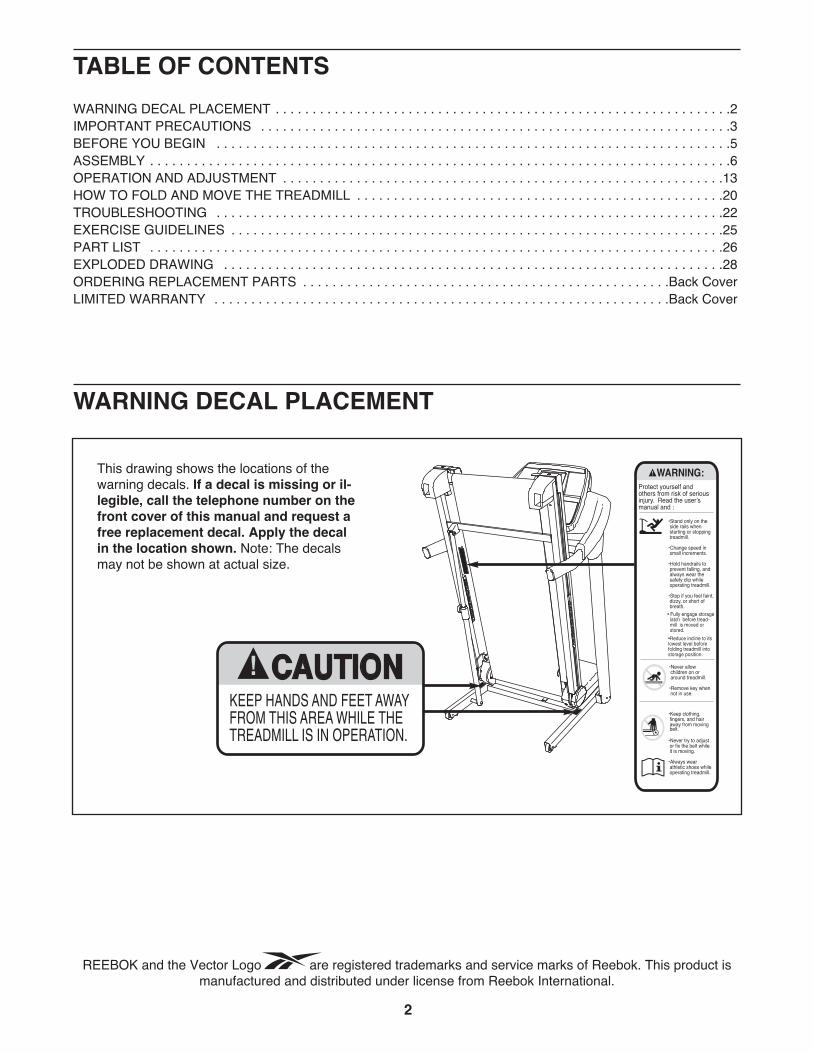
TABLE OF CONTENTSWARNING DECAL PLACEMENT . . . . . . . . . . . . . . . . . . . . . . . . . . . . . . . . . . . . . . . . . . . . . . . . . . . . . . . . . . . . . .2IMPORTANT PRECAUTIONS . . . . . . . . . . . . . . . . . . . . . . . . . . . . . . . . . . . . . . . . . . . . . . . . . . . . . . . . . . . . . . . .3BEFORE YOU BEGIN . . . . . . . . . . . . . . . . . . . . . . . . . . . . . . . . . . . . . . . . . . . . . . . . . . . . . . . . . . . . . . . . . . . . . .5ASSEMBLY . . . . . . . . . . . . . . . . . . . . . . . . . . . . . . . . . . . . . . . . . . . . . . . . . . . . . . . . . . . . . . . . . . . . . . . . . . . . . . .6OPERATION AND ADJUSTMENT . . . . . . . . . . . . . . . . . . . . . . . . . . . . . . . . . . . . . . . . . . . . . . . . . . . . . . . . . . . .13HOW TO FOLD AND MOVE THE TREADMILL . . . . . . . . . . . . . . . . . . . . . . . . . . . . . . . . . . . . . . . . . . . . . . . . . .20TROUBLESHOOTING . . . . . . . . . . . . . . . . . . . . . . . . . . . . . . . . . . . . . . . . . . . . . . . . . . . . . . . . . . . . . . . . . . . . .22EXERCISE GUIDELINES . . . . . . . . . . . . . . . . . . . . . . . . . . . . . . . . . . . . . . . . . . . . . . . . . . . . . . . . . . . . . . . . . . .25PART LIST . . . . . . . . . . . . . . . . . . . . . . . . . . . . . . . . . . . . . . . . . . . . . . . . . . . . . . . . . . . . . . . . . . . . . . . . . . . . . .26EXPLODED DRAWING . . . . . . . . . . . . . . . . . . . . . . . . . . . . . . . . . . . . . . . . . . . . . . . . . . . . . . . . . . . . . . . . . . . .28ORDERING REPLACEMENT PARTS . . . . . . . . . . . . . . . . . . . . . . . . . . . . . . . . . . . . . . . . . . . . . . . . . .Back CoverLIMITED WARRANTY . . . . . . . . . . . . . . . . . . . . . . . . . . . . . . . . . . . . . . . . . . . . . . . . . . . . . . . . . . . . . .Back Cover
This drawing shows the locations of thewarning decals. If a decal is missing or il-legible, call the telephone number on thefront cover of this manual and request afree replacement decal. Apply the decalin the location shown. Note: The decalsmay not be shown at actual size.
WARNING DECAL PLACEMENT
2
REEBOK and the Vector Logo are registered trademarks and service marks of Reebok. This product ismanufactured and distributed under license from Reebok International.

3
1. Before beginning any exercise program, con-sult your physician. This is especially impor-tant for persons over age 35 or persons withpre-existing health problems.
2. It is the responsibility of the owner to ensurethat all users of this treadmill are adequatelyinformed of all warnings and precautions.
3. Use the treadmill only as described.
4. Place the treadmill on a level surface, with atleast 8 ft. (2.4 m) of clearance behind it and 2ft. (0.6 m) on each side. Do not place thetreadmill on any surface that blocks air open-ings. To protect the floor or carpet from dam-age, place a mat under the treadmill.
5. Keep the treadmill indoors, away from mois-ture and dust. Do not put the treadmill in agarage or covered patio, or near water.
6. Do not operate the treadmill where aerosolproducts are used or where oxygen is beingadministered.
7. Keep children under age 12 and pets awayfrom the treadmill at all times.
8. The treadmill should be used only by personsweighing 350 lbs. (159 kg) or less.
9. Never allow more than one person on thetreadmill at a time.
10. Wear appropriate exercise clothes whenusing the treadmill. Do not wear loose clothesthat could become caught in the treadmill.Athletic support clothes are recommendedfor both men and women. Always wear ath-letic shoes. Never use the treadmill with barefeet, wearing only stockings, or in sandals.
11. When connecting the power cord (see page13), plug the power cord into a surge sup-pressor (not included) and plug the surgesuppressor into a grounded circuit capable of
carrying 15 or more amps. No other applianceshould be on the same circuit. Do not use anextension cord.
12. Use only a single-outlet surge suppressor thatmeets all of the specifications described onpage 13. To purchase a surge suppressor, seeyour local REEBOK dealer or call the tele-phone number on the front cover of this man-ual and order part number 146148, or see yourlocal electronics store.
13. Failure to use a properly functioning surgesuppressor could result in damage to the con-trol system of the treadmill. If the control sys-tem is damaged, the walking belt may slow,accelerate, or stop unexpectedly, which mayresult in a fall and serious injury.
14. Keep the power cord and the surge suppres-sor away from heated surfaces.
15. Never move the walking belt while the poweris turned off. Do not operate the treadmill ifthe power cord or plug is damaged, or if thetreadmill is not working properly. (See TROU-BLESHOOTING on page 22 if the treadmill isnot working properly.)
16. Read, understand, and test the emergencystop procedure before using the treadmill (seeHOW TO TURN ON THE POWER on page 15).
17. Never start the treadmill while you are stand-ing on the walking belt. Always hold thehandrails while using the treadmill.
18. The treadmill is capable of high speeds.Adjust the speed in small increments to avoidsudden jumps in speed.
19. The pulse sensor is not a medical device.Various factors, including the user's move-ment, may affect the accuracy of heart ratereadings. The pulse sensor is intended onlyas an exercise aid in determining heart ratetrends in general.
WARNING: To reduce the risk of serious injury, read all important precautions and in-structions in this manual and all warnings on your treadmill before using your treadmill. ICON as-sumes no responsibility for personal injury or property damage sustained by or through the use ofthis product.
IMPORTANT PRECAUTIONS
4
20. Never leave the treadmill unattended while itis running. Always remove the key, unplugthe power cord, and switch the reset/off cir-cuit breaker to the off position when thetreadmill is not in use. (See the drawing onpage 5 for the location of the circuit breaker.)
21. Do not attempt to raise, lower, or move thetreadmill until it is properly assembled. (SeeASSEMBLY on page 6, and HOW TO FOLDAND MOVE THE TREADMILL on page 20.)You must be able to safely lift 45 lbs. (20 kg)to raise, lower, or move the treadmill.
22. When folding or moving the treadmill, makesure that the storage latch is holding theframe securely in the storage position.
23. Never insert any object into any opening onthe treadmill.
24. Inspect and properly tighten all parts of thetreadmill regularly.
25. DANGER: Always unplug the powercord immediately after use, before cleaning thetreadmill, and before performing the mainte-nance and adjustment procedures described inthis manual. Never remove the motor hood un-less instructed to do so by an authorized ser-vice representative. Servicing other than theprocedures in this manual should be performedby an authorized service representative only.
26. This treadmill is intended for in-home useonly. Do not use this treadmill in a commer-cial, rental, or institutional setting.
27. Over exercising may result in serious injuryor death. If you feel faint or if you experiencepain while exercising, stop immediately andcool down.
SAVE THESE INSTRUCTIONS
5
Thank you for selecting the revolutionary REEBOK®
V8.90 treadmill. The V8.90 treadmill offers an impres-sive selection of features designed to make your work-outs at home more enjoyable and effective. And whenyouʼre not exercising, the unique treadmill can befolded up, requiring less than half the floor space ofother treadmills.
For your benefit, read this manual carefully beforeusing the treadmill. If you have questions after read-
ing this manual, please see the front cover of this man-ual. To help us assist you, please note the productmodel number and serial number before contacting us.The model number and the location of the serial num-ber decal are shown on the front cover of this manual.
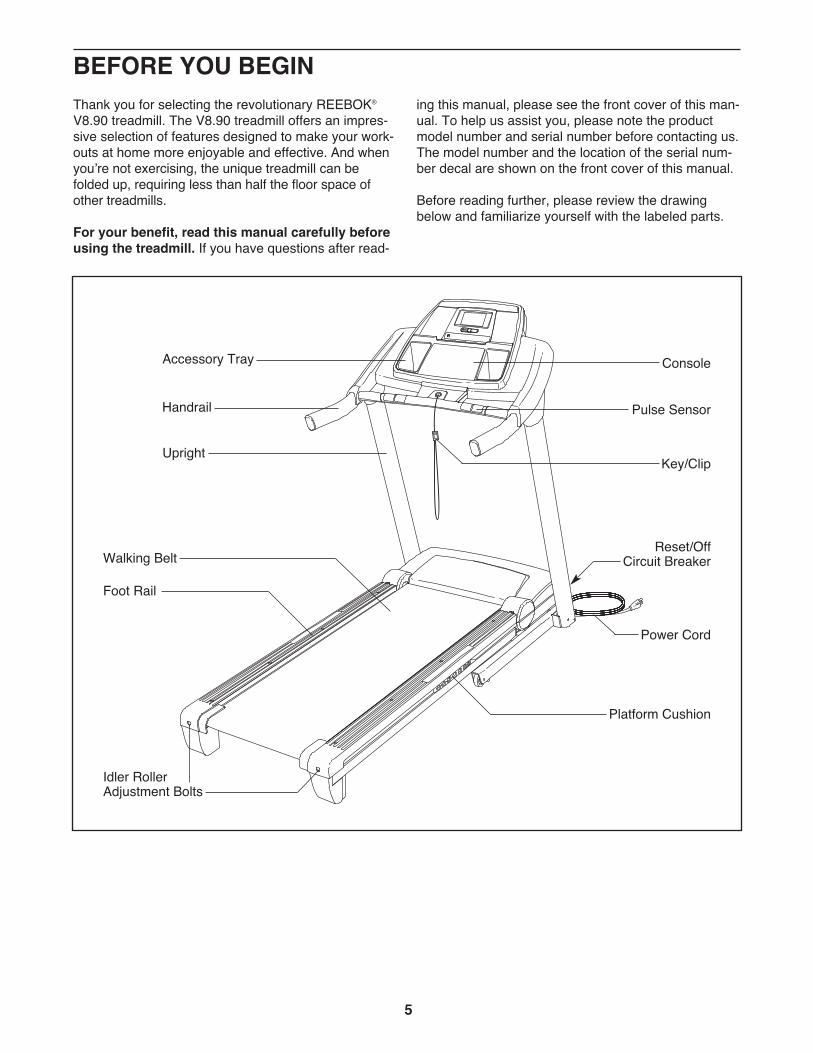
Before reading further, please review the drawingbelow and familiarize yourself with the labeled parts.
BEFORE YOU BEGIN
Handrail
Upright
Accessory Tray
Key/Clip
Reset/OffCircuit BreakerWalking Belt
Platform Cushion
Foot Rail
Power Cord
Idler RollerAdjustment Bolts
Console
Pulse Sensor
6
ASSEMBLYTo hire an authorized service technician to assemble the treadmill, call 1-800-445-2480.
Assembly requires two persons. Set the treadmill in a cleared area and remove all packing materials. Do notdispose of the packing materials until assembly is completed. Note: The underside of the treadmill walkingbelt is coated with high-performance lubricant. During shipping, some lubricant may be transferred to the top ofthe walking belt or the shipping carton. This is normal and does not affect treadmill performance. If there is lubri-cant on top of the walking belt, simply wipe off the lubricant with a soft cloth and a mild, non-abrasive cleaner.
Assembly requires the included hex keys and your own Phillips screwdriver ,adjustable wrench , needlenose pliers , and scissors .
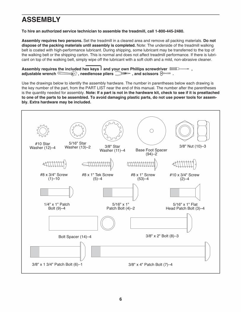
Use the drawings below to identify the assembly hardware. The number in parentheses below each drawing isthe key number of the part, from the PART LIST near the end of this manual. The number after the parenthesesis the quantity needed for assembly. Note: If a part is not in the hardware kit, check to see if it is preattachedto one of the parts to be assembled. To avoid damaging plastic parts, do not use power tools for assem-bly. Extra hardware may be included.
Base Foot Spacer(94)–2
#8 x 3/4" Screw(1)–10
3/8" StarWasher (11)–4
#8 x 1" Tek Screw(5)–4
3/8" Nut (10)–35/16" StarWasher (13)–2
#10 x 3/4" Screw(2)–4
#10 StarWasher (12)–4
3/8" x 4" Patch Bolt (7)–4
Bolt Spacer (14)–4
5/16" x 1"Patch Bolt (4)–2
#8 x 1" Screw(53)–4
1/4" x 1" PatchBolt (9)–4
3/8" x 2" Bolt (8)–3
3/8" x 1 3/4" Patch Bolt (6)–1
5/16" x 1" FlatHead Patch Bolt (3)–4
7
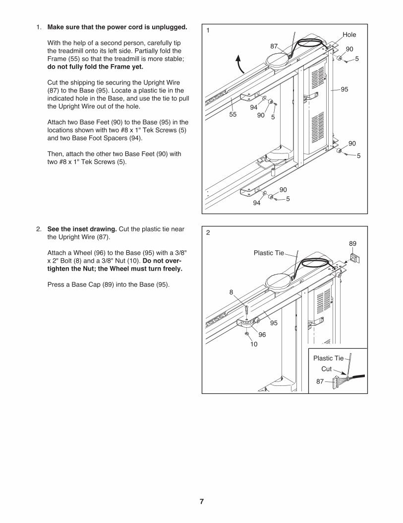
2. See the inset drawing. Cut the plastic tie nearthe Upright Wire (87).
Attach a Wheel (96) to the Base (95) with a 3/8"x 2" Bolt (8) and a 3/8" Nut (10). Do not over-tighten the Nut; the Wheel must turn freely.
Press a Base Cap (89) into the Base (95).
95
8
10
2
96
89
1. Make sure that the power cord is unplugged.
With the help of a second person, carefully tipthe treadmill onto its left side. Partially fold theFrame (55) so that the treadmill is more stable;do not fully fold the Frame yet.
Cut the shipping tie securing the Upright Wire(87) to the Base (95). Locate a plastic tie in theindicated hole in the Base, and use the tie to pullthe Upright Wire out of the hole.
Attach two Base Feet (90) to the Base (95) in thelocations shown with two #8 x 1" Tek Screws (5)and two Base Foot Spacers (94).
Then, attach the other two Base Feet (90) withtwo #8 x 1" Tek Screws (5).
1
95
5
55
90
90
5
5
590
9490
87Hole
94
Plastic Tie
Cut87
Plastic Tie
8
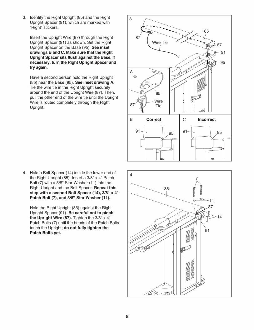
4. Hold a Bolt Spacer (14) inside the lower end ofthe Right Upright (85). Insert a 3/8" x 4" PatchBolt (7) with a 3/8" Star Washer (11) into theRight Upright and the Bolt Spacer. Repeat thisstep with a second Bolt Spacer (14), 3/8" x 4"Patch Bolt (7), and 3/8" Star Washer (11).
Hold the Right Upright (85) against the RightUpright Spacer (91). Be careful not to pinchthe Upright Wire (87). Tighten the 3/8" x 4"Patch Bolts (7) until the heads of the Patch Boltstouch the Upright; do not fully tighten thePatch Bolts yet. 91
85
8711
14
74
3. Identify the Right Upright (85) and the RightUpright Spacer (91), which are marked with“Right” stickers.
Insert the Upright Wire (87) through the RightUpright Spacer (91) as shown. Set the RightUpright Spacer on the Base (95). See insetdrawings B and C. Make sure that the RightUpright Spacer sits flush against the Base. Ifnecessary, turn the Right Upright Spacer andtry again.
Have a second person hold the Right Upright(85) near the Base (95). See inset drawing A.Tie the wire tie in the Right Upright securelyaround the end of the Upright Wire (87). Then,pull the other end of the wire tie until the UprightWire is routed completely through the RightUpright.
95
Wire Tie87
85
9187
3
WireTie
85
87
A
91
Incorrect
91 9595
B CCorrect
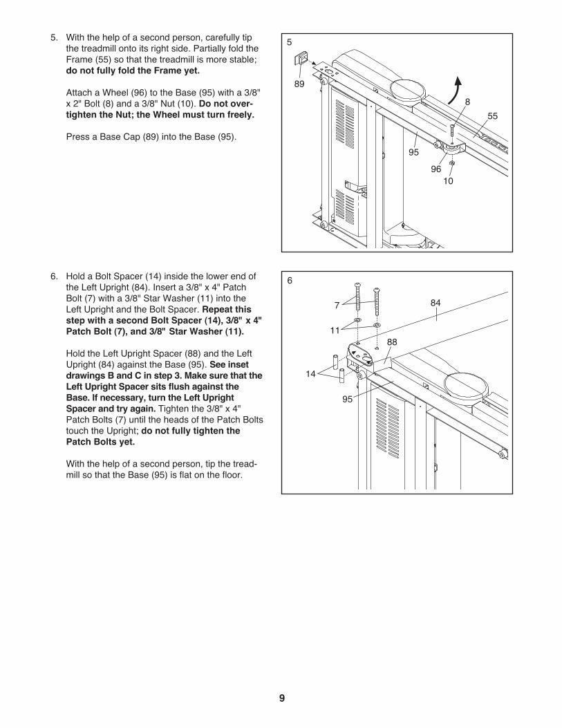
6. Hold a Bolt Spacer (14) inside the lower end ofthe Left Upright (84). Insert a 3/8" x 4" PatchBolt (7) with a 3/8" Star Washer (11) into theLeft Upright and the Bolt Spacer. Repeat thisstep with a second Bolt Spacer (14), 3/8" x 4"Patch Bolt (7), and 3/8" Star Washer (11).
Hold the Left Upright Spacer (88) and the LeftUpright (84) against the Base (95). See insetdrawings B and C in step 3. Make sure that theLeft Upright Spacer sits flush against theBase. If necessary, turn the Left UprightSpacer and try again. Tighten the 3/8" x 4"Patch Bolts (7) until the heads of the Patch Boltstouch the Upright; do not fully tighten thePatch Bolts yet.
With the help of a second person, tip the tread-mill so that the Base (95) is flat on the floor.
88
847
95
14
11
6
9
5. With the help of a second person, carefully tipthe treadmill onto its right side. Partially fold theFrame (55) so that the treadmill is more stable;do not fully fold the Frame yet.
Attach a Wheel (96) to the Base (95) with a 3/8"x 2" Bolt (8) and a 3/8" Nut (10). Do not over-tighten the Nut; the Wheel must turn freely.
Press a Base Cap (89) into the Base (95).
5
855
10
95
89
96
10
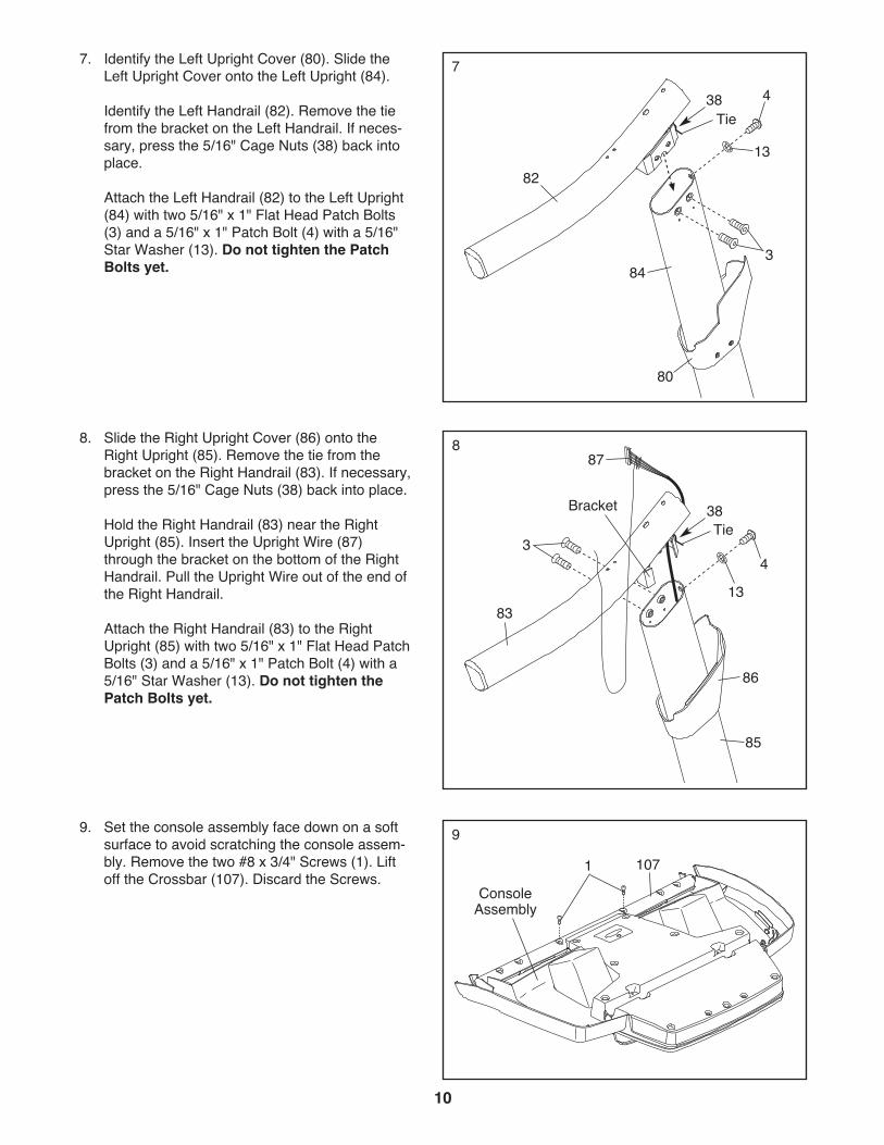
8. Slide the Right Upright Cover (86) onto theRight Upright (85). Remove the tie from thebracket on the Right Handrail (83). If necessary,press the 5/16" Cage Nuts (38) back into place.
Hold the Right Handrail (83) near the RightUpright (85). Insert the Upright Wire (87)through the bracket on the bottom of the RightHandrail. Pull the Upright Wire out of the end ofthe Right Handrail.
Attach the Right Handrail (83) to the RightUpright (85) with two 5/16" x 1" Flat Head PatchBolts (3) and a 5/16" x 1" Patch Bolt (4) with a5/16" Star Washer (13). Do not tighten thePatch Bolts yet.
9. Set the console assembly face down on a softsurface to avoid scratching the console assem-bly. Remove the two #8 x 3/4" Screws (1). Liftoff the Crossbar (107). Discard the Screws.
9
107Console
Assembly
1
83
Bracket
34
13
86
85
878
7. Identify the Left Upright Cover (80). Slide theLeft Upright Cover onto the Left Upright (84).
Identify the Left Handrail (82). Remove the tiefrom the bracket on the Left Handrail. If neces-sary, press the 5/16" Cage Nuts (38) back intoplace.
Attach the Left Handrail (82) to the Left Upright(84) with two 5/16" x 1" Flat Head Patch Bolts(3) and a 5/16" x 1" Patch Bolt (4) with a 5/16"Star Washer (13). Do not tighten the PatchBolts yet.
82
4
3
13
84
80
7
Tie38
Tie38
11
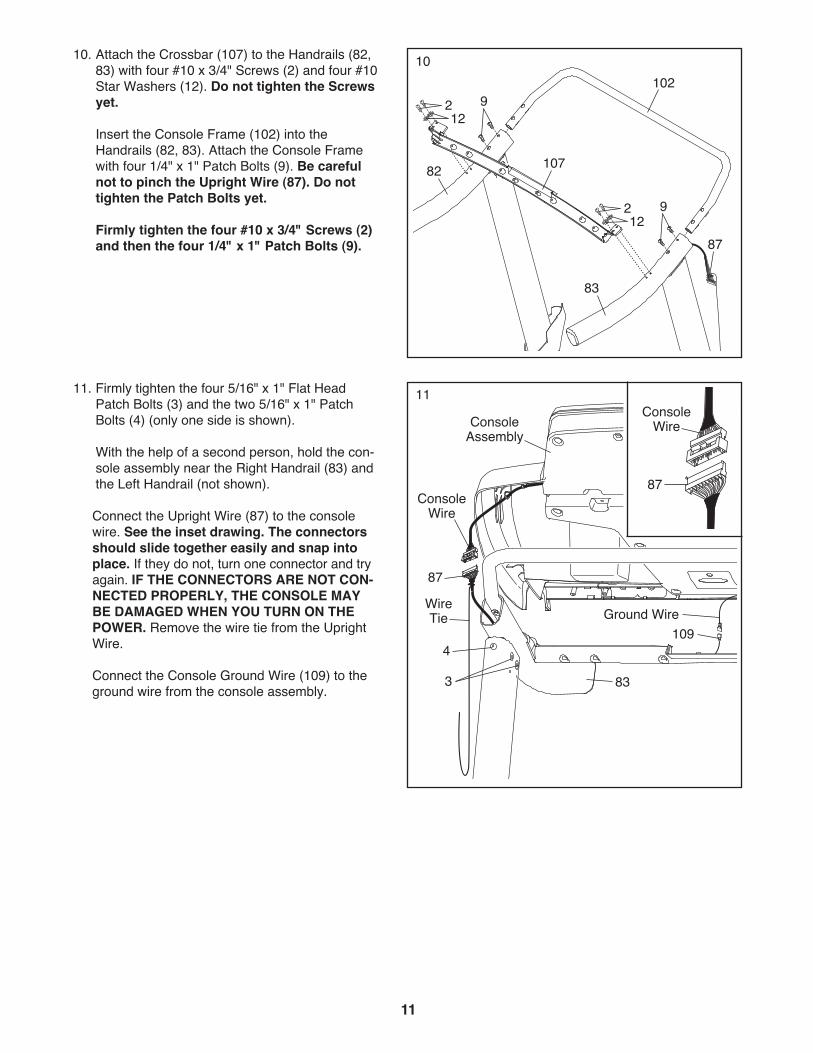
11. Firmly tighten the four 5/16" x 1" Flat HeadPatch Bolts (3) and the two 5/16" x 1" PatchBolts (4) (only one side is shown).
With the help of a second person, hold the con-sole assembly near the Right Handrail (83) andthe Left Handrail (not shown).
Connect the Upright Wire (87) to the consolewire. See the inset drawing. The connectorsshould slide together easily and snap intoplace. If they do not, turn one connector and tryagain. IF THE CONNECTORS ARE NOT CON-NECTED PROPERLY, THE CONSOLE MAYBE DAMAGED WHEN YOU TURN ON THEPOWER. Remove the wire tie from the UprightWire.
Connect the Console Ground Wire (109) to theground wire from the console assembly.
ConsoleAssembly
11
ConsoleWire
WireTie Ground Wire
83
87
4
3
109
87
ConsoleWire
10. Attach the Crossbar (107) to the Handrails (82,83) with four #10 x 3/4" Screws (2) and four #10Star Washers (12). Do not tighten the Screwsyet.
Insert the Console Frame (102) into theHandrails (82, 83). Attach the Console Framewith four 1/4" x 1" Patch Bolts (9). Be carefulnot to pinch the Upright Wire (87). Do nottighten the Patch Bolts yet.
Firmly tighten the four #10 x 3/4" Screws (2)and then the four 1/4" x 1" Patch Bolts (9).
10
107
1292
83
102
82
87
912
2
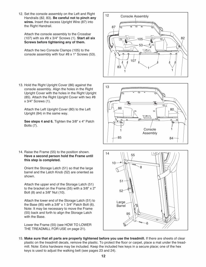
13. Hold the Right Upright Cover (86) against theconsole assembly. Align the holes in the RightUpright Cover with the holes in the Right Upright(85). Attach the Right Upright Cover with two #8x 3/4" Screws (1).
Attach the Left Upright Cover (80) to the LeftUpright (84) in the same way.
See steps 4 and 6. Tighten the 3/8" x 4" PatchBolts (7).
13
85 84
1 1ConsoleAssembly
15. Make sure that all parts are properly tightened before you use the treadmill. If there are sheets of clearplastic on the treadmill decals, remove the plastic. To protect the floor or carpet, place a mat under the tread-mill. Note: Extra hardware may be included. Keep the included hex keys in a secure place; one of the hexkeys is used to adjust the walking belt (see pages 23 and 24).
14. Raise the Frame (55) to the position shown.Have a second person hold the Frame untilthis step is completed.
Orient the Storage Latch (51) so that the largebarrel and the Latch Knob (52) are oriented asshown.
Attach the upper end of the Storage Latch (51)to the bracket on the Frame (55) with a 3/8" x 2"Bolt (8) and a 3/8" Nut (10).
Attach the lower end of the Storage Latch (51) tothe Base (95) with a 3/8" x 1 3/4" Patch Bolt (6).Note: It may be necessary to move the Frame(55) back and forth to align the Storage Latchwith the Base.
Lower the Frame (55) (see HOW TO LOWERTHE TREADMILL FOR USE on page 21).
51
95
10
LargeBarrel
6
5514
8
52
86 80
12
12. Set the console assembly on the Left and RightHandrails (82, 83). Be careful not to pinch anywires. Insert the excess Upright Wire (87) intothe Right Handrail.
Attach the console assembly to the Crossbar(107) with six #8 x 3/4" Screws (1). Start all sixScrews before tightening any of them.
Attach the two Console Clamps (105) to theconsole assembly with four #8 x 1" Screws (53).
12
83
10553
87
11 1
Console Assembly
82
107
13
OPERATION AND ADJUSTMENTTHE PRE-LUBRICATED WALKING BELT
Your treadmill features a walking belt coated with high-performance lubricant. IMPORTANT: Never apply sil-icone spray or other substances to the walkingbelt or the walking platform. Such substances willdeteriorate the walking belt and cause excessivewear.
HOW TO PLUG IN THE POWER CORD
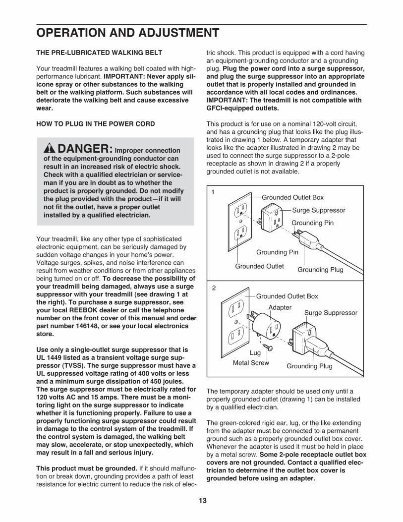
Your treadmill, like any other type of sophisticatedelectronic equipment, can be seriously damaged bysudden voltage changes in your homeʼs power.Voltage surges, spikes, and noise interference canresult from weather conditions or from other appliancesbeing turned on or off. To decrease the possibility ofyour treadmill being damaged, always use a surgesuppressor with your treadmill (see drawing 1 atthe right). To purchase a surge suppressor, seeyour local REEBOK dealer or call the telephonenumber on the front cover of this manual and orderpart number 146148, or see your local electronicsstore.
Use only a single-outlet surge suppressor that isUL 1449 listed as a transient voltage surge sup-pressor (TVSS). The surge suppressor must have aUL suppressed voltage rating of 400 volts or lessand a minimum surge dissipation of 450 joules.The surge suppressor must be electrically rated for120 volts AC and 15 amps. There must be a moni-toring light on the surge suppressor to indicatewhether it is functioning properly. Failure to use aproperly functioning surge suppressor could resultin damage to the control system of the treadmill. Ifthe control system is damaged, the walking beltmay slow, accelerate, or stop unexpectedly, whichmay result in a fall and serious injury.
This product must be grounded. If it should malfunc-tion or break down, grounding provides a path of leastresistance for electric current to reduce the risk of elec-
tric shock. This product is equipped with a cord havingan equipment-grounding conductor and a groundingplug. Plug the power cord into a surge suppressor,and plug the surge suppressor into an appropriateoutlet that is properly installed and grounded inaccordance with all local codes and ordinances.IMPORTANT: The treadmill is not compatible withGFCI-equipped outlets.
This product is for use on a nominal 120-volt circuit,and has a grounding plug that looks like the plug illus-trated in drawing 1 below. A temporary adapter thatlooks like the adapter illustrated in drawing 2 may beused to connect the surge suppressor to a 2-polereceptacle as shown in drawing 2 if a properlygrounded outlet is not available.
The temporary adapter should be used only until aproperly grounded outlet (drawing 1) can be installedby a qualified electrician.
The green-colored rigid ear, lug, or the like extendingfrom the adapter must be connected to a permanentground such as a properly grounded outlet box cover.Whenever the adapter is used it must be held in placeby a metal screw. Some 2-pole receptacle outlet boxcovers are not grounded. Contact a qualified elec-trician to determine if the outlet box cover isgrounded before using an adapter.
DANGER: Improper connectionof the equipment-grounding conductor canresult in an increased risk of electric shock.Check with a qualified electrician or service-man if you are in doubt as to whether theproduct is properly grounded. Do not modifythe plug provided with the product—if it willnot fit the outlet, have a proper outletinstalled by a qualified electrician.
1
2
Grounded Outlet Box
Grounded Outlet Box
Grounding Plug
Surge Suppressor
Surge Suppressor
Grounding Pin
Adapter
LugMetal Screw
Grounded Outlet
Grounding Pin
Grounding Plug
14
FEATURES OF THE CONSOLE
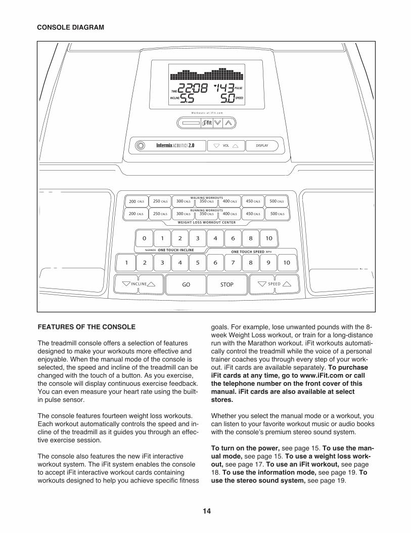
The treadmill console offers a selection of featuresdesigned to make your workouts more effective andenjoyable. When the manual mode of the console isselected, the speed and incline of the treadmill can bechanged with the touch of a button. As you exercise,the console will display continuous exercise feedback.You can even measure your heart rate using the built-in pulse sensor.
The console features fourteen weight loss workouts.Each workout automatically controls the speed and in-cline of the treadmill as it guides you through an effec-tive exercise session.
The console also features the new iFit interactiveworkout system. The iFit system enables the consoleto accept iFit interactive workout cards containingworkouts designed to help you achieve specific fitness
goals. For example, lose unwanted pounds with the 8-week Weight Loss workout, or train for a long-distancerun with the Marathon workout. iFit workouts automati-cally control the treadmill while the voice of a personaltrainer coaches you through every step of your work-out. iFit cards are available separately. To purchaseiFit cards at any time, go to www.iFit.com or callthe telephone number on the front cover of thismanual. iFit cards are also available at selectstores.
Whether you select the manual mode or a workout, youcan listen to your favorite workout music or audio bookswith the consoleʼs premium stereo sound system.
To turn on the power, see page 15. To use the man-ual mode, see page 15. To use a weight loss work-out, see page 17. To use an iFit workout, see page18. To use the information mode, see page 19. Touse the stereo sound system, see page 19.
CONSOLE DIAGRAM
15
HOW TO TURN ON THE POWER
IMPORTANT: If the treadmill has been exposed tocold temperatures, allow it to warm to room tem-perature before turning on the power. If you do notdo this, you may damage the console displays orother electrical components.
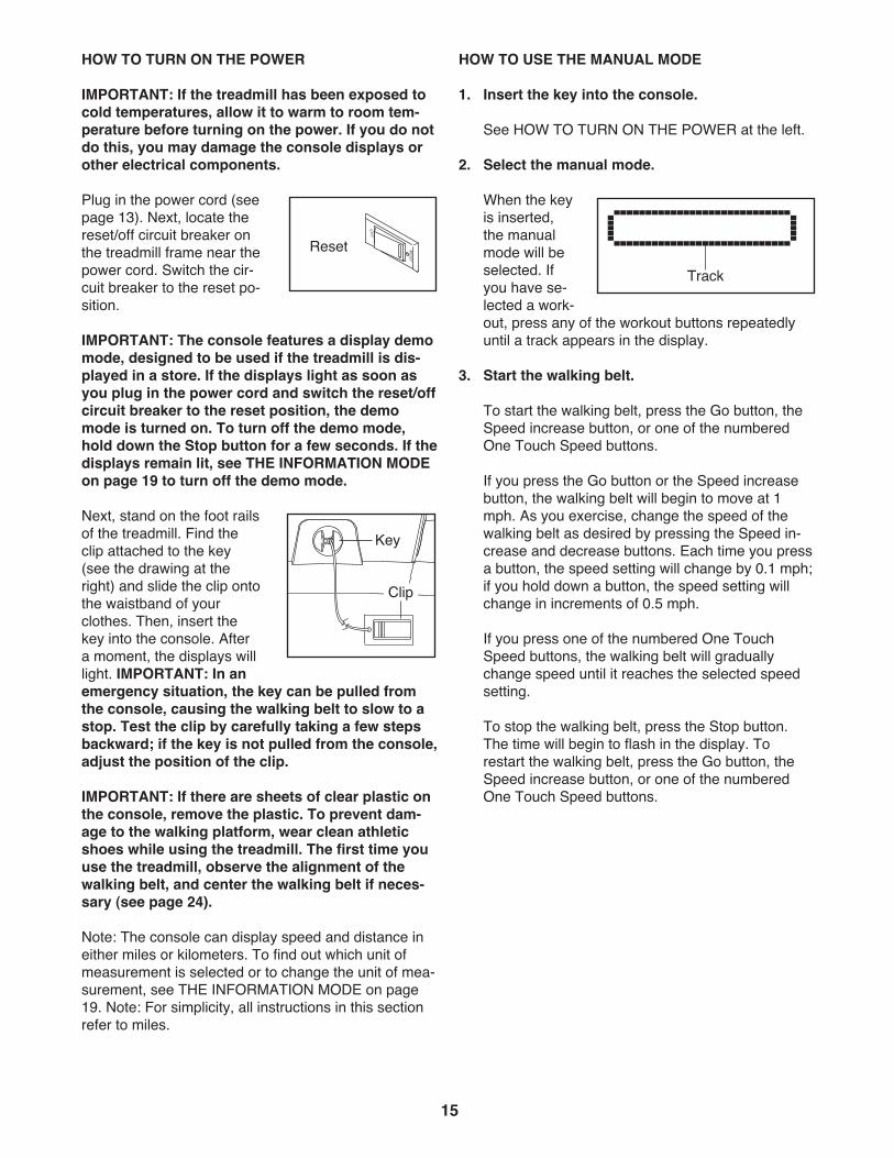
Plug in the power cord (seepage 13). Next, locate thereset/off circuit breaker onthe treadmill frame near thepower cord. Switch the cir-cuit breaker to the reset po-sition.
IMPORTANT: The console features a display demomode, designed to be used if the treadmill is dis-played in a store. If the displays light as soon asyou plug in the power cord and switch the reset/offcircuit breaker to the reset position, the demomode is turned on. To turn off the demo mode,hold down the Stop button for a few seconds. If thedisplays remain lit, see THE INFORMATION MODEon page 19 to turn off the demo mode.
Next, stand on the foot railsof the treadmill. Find theclip attached to the key(see the drawing at theright) and slide the clip ontothe waistband of yourclothes. Then, insert thekey into the console. Aftera moment, the displays willlight. IMPORTANT: In anemergency situation, the key can be pulled fromthe console, causing the walking belt to slow to astop. Test the clip by carefully taking a few stepsbackward; if the key is not pulled from the console,adjust the position of the clip.
IMPORTANT: If there are sheets of clear plastic onthe console, remove the plastic. To prevent dam-age to the walking platform, wear clean athleticshoes while using the treadmill. The first time youuse the treadmill, observe the alignment of thewalking belt, and center the walking belt if neces-sary (see page 24).
Note: The console can display speed and distance ineither miles or kilometers. To find out which unit ofmeasurement is selected or to change the unit of mea-surement, see THE INFORMATION MODE on page19. Note: For simplicity, all instructions in this sectionrefer to miles.
HOW TO USE THE MANUAL MODE
1. Insert the key into the console.
See HOW TO TURN ON THE POWER at the left.
2. Select the manual mode.
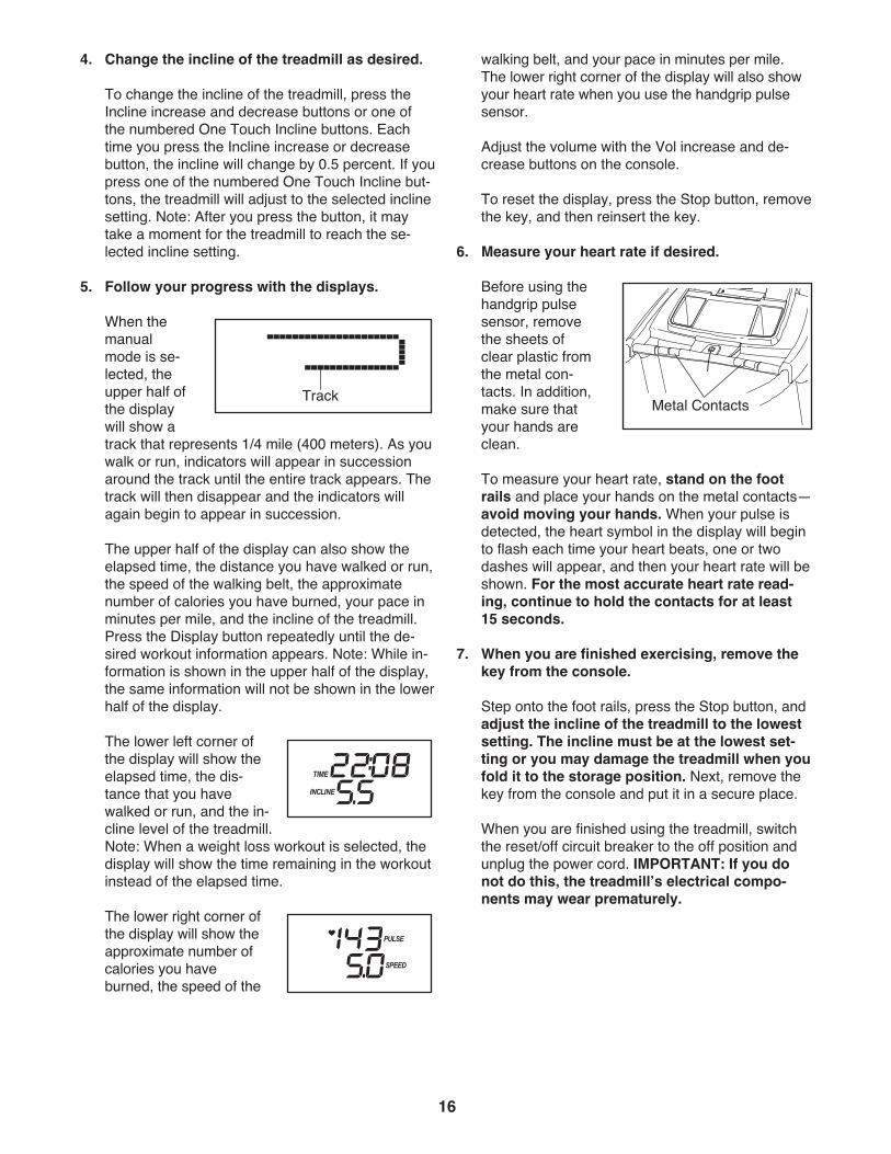
When the keyis inserted,the manualmode will beselected. Ifyou have se-lected a work-out, press any of the workout buttons repeatedlyuntil a track appears in the display.
3. Start the walking belt.
To start the walking belt, press the Go button, theSpeed increase button, or one of the numberedOne Touch Speed buttons.
If you press the Go button or the Speed increasebutton, the walking belt will begin to move at 1mph. As you exercise, change the speed of thewalking belt as desired by pressing the Speed in-crease and decrease buttons. Each time you pressa button, the speed setting will change by 0.1 mph;if you hold down a button, the speed setting willchange in increments of 0.5 mph.
If you press one of the numbered One TouchSpeed buttons, the walking belt will graduallychange speed until it reaches the selected speedsetting.
To stop the walking belt, press the Stop button.The time will begin to flash in the display. Torestart the walking belt, press the Go button, theSpeed increase button, or one of the numberedOne Touch Speed buttons.
Track
Reset
Key
Clip
16
4. Change the incline of the treadmill as desired.
To change the incline of the treadmill, press theIncline increase and decrease buttons or one ofthe numbered One Touch Incline buttons. Eachtime you press the Incline increase or decreasebutton, the incline will change by 0.5 percent. If youpress one of the numbered One Touch Incline but-tons, the treadmill will adjust to the selected inclinesetting. Note: After you press the button, it maytake a moment for the treadmill to reach the se-lected incline setting.
5. Follow your progress with the displays.
When themanualmode is se-lected, theupper half ofthe displaywill show atrack that represents 1/4 mile (400 meters). As youwalk or run, indicators will appear in successionaround the track until the entire track appears. Thetrack will then disappear and the indicators willagain begin to appear in succession.
The upper half of the display can also show theelapsed time, the distance you have walked or run,the speed of the walking belt, the approximatenumber of calories you have burned, your pace inminutes per mile, and the incline of the treadmill.Press the Display button repeatedly until the de-sired workout information appears. Note: While in-formation is shown in the upper half of the display,the same information will not be shown in the lowerhalf of the display.
The lower left corner ofthe display will show theelapsed time, the dis-tance that you havewalked or run, and the in-cline level of the treadmill.Note: When a weight loss workout is selected, thedisplay will show the time remaining in the workoutinstead of the elapsed time.
The lower right corner ofthe display will show theapproximate number ofcalories you haveburned, the speed of the
walking belt, and your pace in minutes per mile.The lower right corner of the display will also showyour heart rate when you use the handgrip pulsesensor.
Adjust the volume with the Vol increase and de-crease buttons on the console.
To reset the display, press the Stop button, removethe key, and then reinsert the key.
6. Measure your heart rate if desired.
Before using thehandgrip pulsesensor, removethe sheets ofclear plastic fromthe metal con-tacts. In addition,make sure thatyour hands areclean.
To measure your heart rate, stand on the footrails and place your hands on the metal contacts—avoid moving your hands. When your pulse isdetected, the heart symbol in the display will beginto flash each time your heart beats, one or twodashes will appear, and then your heart rate will beshown. For the most accurate heart rate read-ing, continue to hold the contacts for at least15 seconds.
7. When you are finished exercising, remove thekey from the console.
Step onto the foot rails, press the Stop button, andadjust the incline of the treadmill to the lowestsetting. The incline must be at the lowest set-ting or you may damage the treadmill when youfold it to the storage position. Next, remove thekey from the console and put it in a secure place.
When you are finished using the treadmill, switchthe reset/off circuit breaker to the off position andunplug the power cord. IMPORTANT: If you donot do this, the treadmillʼs electrical compo-nents may wear prematurely.
Track Metal Contacts
17
HOW TO USE A WEIGHT LOSS WORKOUT
1. Insert the key into the console.
See HOW TO TURN ON THE POWER on page 15.
2. Select one of the weight loss workouts.
To select one of the fourteen weight loss workouts,press one of the Weight Loss Workout Center but-tons.
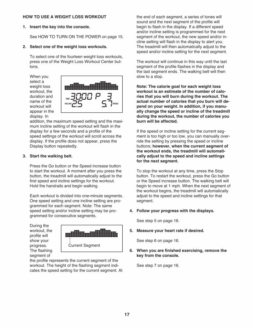
When youselect aweight lossworkout, theduration andname of theworkout willappear in thedisplay. Inaddition, the maximum speed setting and the maxi-mum incline setting of the workout will flash in thedisplay for a few seconds and a profile of thespeed settings of the workout will scroll across thedisplay. If the profile does not appear, press theDisplay button repeatedly.
3. Start the walking belt.
Press the Go button or the Speed increase buttonto start the workout. A moment after you press thebutton, the treadmill will automatically adjust to thefirst speed and incline settings for the workout.Hold the handrails and begin walking.
Each workout is divided into one-minute segments.One speed setting and one incline setting are pro-grammed for each segment. Note: The samespeed setting and/or incline setting may be pro-grammed for consecutive segments.
During theworkout, theprofile willshow yourprogress.The flashingsegment ofthe profile represents the current segment of theworkout. The height of the flashing segment indi-cates the speed setting for the current segment. At
the end of each segment, a series of tones willsound and the next segment of the profile willbegin to flash in the display. If a different speedand/or incline setting is programmed for the nextsegment of the workout, the new speed and/or in-cline setting will flash in the display to alert you.The treadmill will then automatically adjust to thespeed and/or incline setting for the next segment.
The workout will continue in this way until the lastsegment of the profile flashes in the display andthe last segment ends. The walking belt will thenslow to a stop.
Note: The calorie goal for each weight lossworkout is an estimate of the number of calo-ries that you will burn during the workout. Theactual number of calories that you burn will de-pend on your weight. In addition, if you manu-ally change the speed or incline of the treadmillduring the workout, the number of calories youburn will be affected.
If the speed or incline setting for the current seg-ment is too high or too low, you can manually over-ride the setting by pressing the speed or inclinebuttons; however, when the current segment ofthe workout ends, the treadmill will automati-cally adjust to the speed and incline settingsfor the next segment.
To stop the workout at any time, press the Stopbutton. To restart the workout, press the Go buttonor the Speed increase button. The walking belt willbegin to move at 1 mph. When the next segment ofthe workout begins, the treadmill will automaticallyadjust to the speed and incline settings for thatsegment.
4. Follow your progress with the displays.
See step 5 on page 16.
5. Measure your heart rate if desired.
See step 6 on page 16.
6. When you are finished exercising, remove thekey from the console.
See step 7 on page 16.
Current Segment
18
HOW TO USE AN IFIT WORKOUT
To purchase iFit cards at any time, go to www.iFit.comor call the telephone number on the front cover of thismanual. iFit cards are also available at select stores.
1. Insert the key into the console.
See HOW TO TURN ON THE POWER on page 15.
2. Insert an iFit card and select a workout.
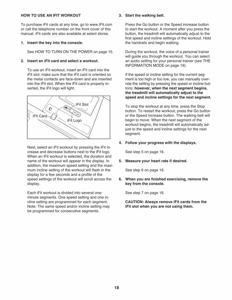
To use an iFit workout, insert an iFit card into theiFit slot; make sure that the iFit card is oriented sothe metal contacts are face-down and are insertedinto the iFit slot. When the iFit card is properly in-serted, the iFit logo will light.
Next, select an iFit workout by pressing the iFit in-crease and decrease buttons next to the iFit logo.When an iFit workout is selected, the duration andname of the workout will appear in the display. Inaddition, the maximum speed setting and the maxi-mum incline setting of the workout will flash in thedisplay for a few seconds and a profile of thespeed settings of the workout will scroll across thedisplay.
Each iFit workout is divided into several one-minute segments. One speed setting and one in-cline setting are programmed for each segment.Note: The same speed and/or incline setting maybe programmed for consecutive segments.
3. Start the walking belt.
Press the Go button or the Speed increase buttonto start the workout. A moment after you press thebutton, the treadmill will automatically adjust to thefirst speed and incline settings of the workout. Holdthe handrails and begin walking.
During the workout, the voice of a personal trainerwill guide you through the workout. You can selectan audio setting for your personal trainer (see THEINFORMATION MODE on page 19).
If the speed or incline setting for the current seg-ment is too high or too low, you can manually over-ride the setting by pressing the speed or incline but-tons; however, when the next segment begins,the treadmill will automatically adjust to thespeed and incline settings for the next segment.
To stop the workout at any time, press the Stopbutton. To restart the workout, press the Go buttonor the Speed increase button. The walking belt willbegin to move. When the next segment of theworkout begins, the treadmill will automatically ad-just to the speed and incline settings for the nextsegment.
4. Follow your progress with the displays.
See step 5 on page 16.
5. Measure your heart rate if desired.
See step 6 on page 16.
6. When you are finished exercising, remove thekey from the console.
See step 7 on page 16.
CAUTION: Always remove iFit cards from theiFit slot when you are not using them.
iFit Card
iFit Slot
iFit Logo
19
THE INFORMATION MODE
The console features an information mode that keepstrack of treadmill usage information. The informationmode also allows you to select miles or kilometers asthe unit of measurement and to turn on and turn off thedisplay demo mode. You can also turn on or turn offthe personal trainer and adjust the volume level.
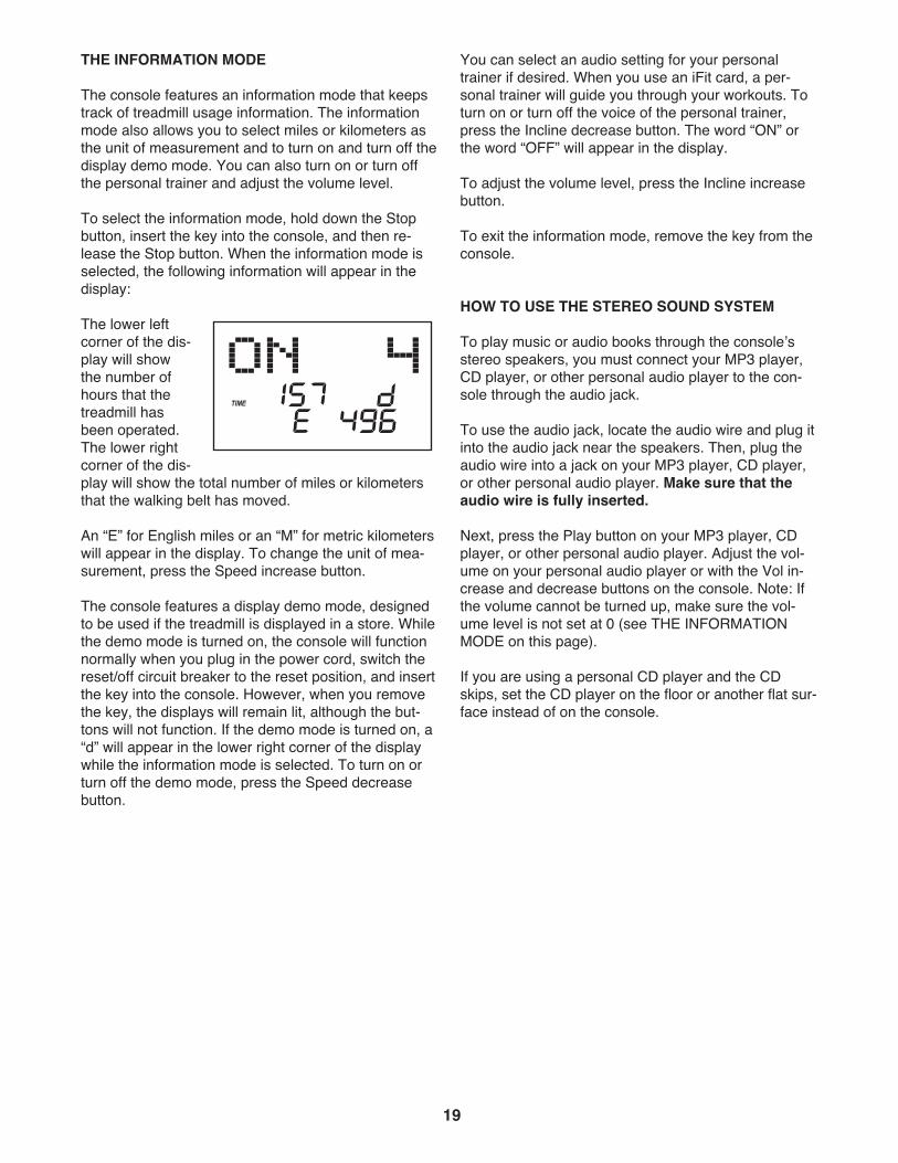
To select the information mode, hold down the Stopbutton, insert the key into the console, and then re-lease the Stop button. When the information mode isselected, the following information will appear in thedisplay:
The lower leftcorner of the dis-play will showthe number ofhours that thetreadmill hasbeen operated.The lower rightcorner of the dis-play will show the total number of miles or kilometersthat the walking belt has moved.
An “E” for English miles or an “M” for metric kilometerswill appear in the display. To change the unit of mea-surement, press the Speed increase button.
The console features a display demo mode, designedto be used if the treadmill is displayed in a store. Whilethe demo mode is turned on, the console will functionnormally when you plug in the power cord, switch thereset/off circuit breaker to the reset position, and insertthe key into the console. However, when you removethe key, the displays will remain lit, although the but-tons will not function. If the demo mode is turned on, a“d” will appear in the lower right corner of the displaywhile the information mode is selected. To turn on orturn off the demo mode, press the Speed decreasebutton.
You can select an audio setting for your personaltrainer if desired. When you use an iFit card, a per-sonal trainer will guide you through your workouts. Toturn on or turn off the voice of the personal trainer,press the Incline decrease button. The word “ON” orthe word “OFF” will appear in the display.
To adjust the volume level, press the Incline increasebutton.
To exit the information mode, remove the key from theconsole.
HOW TO USE THE STEREO SOUND SYSTEM
To play music or audio books through the consoleʼsstereo speakers, you must connect your MP3 player,CD player, or other personal audio player to the con-sole through the audio jack.
To use the audio jack, locate the audio wire and plug itinto the audio jack near the speakers. Then, plug theaudio wire into a jack on your MP3 player, CD player,or other personal audio player. Make sure that theaudio wire is fully inserted.
Next, press the Play button on your MP3 player, CDplayer, or other personal audio player. Adjust the vol-ume on your personal audio player or with the Vol in-crease and decrease buttons on the console. Note: Ifthe volume cannot be turned up, make sure the vol-ume level is not set at 0 (see THE INFORMATIONMODE on this page).
If you are using a personal CD player and the CDskips, set the CD player on the floor or another flat sur-face instead of on the console.
20
HOW TO FOLD AND MOVE THE TREADMILLHOW TO FOLD THE TREADMILL FOR STORAGE
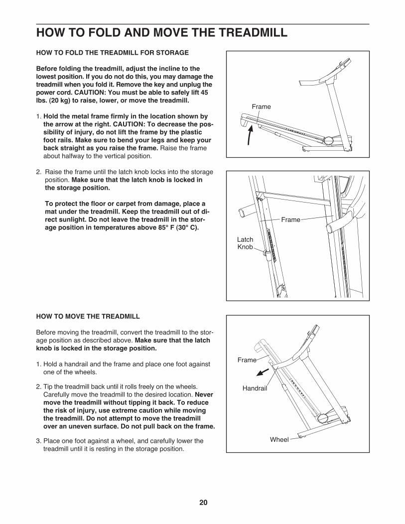
Before folding the treadmill, adjust the incline to thelowest position. If you do not do this, you may damage thetreadmill when you fold it. Remove the key and unplug thepower cord. CAUTION: You must be able to safely lift 45lbs. (20 kg) to raise, lower, or move the treadmill.
1. Hold the metal frame firmly in the location shown bythe arrow at the right. CAUTION: To decrease the pos-sibility of injury, do not lift the frame by the plasticfoot rails. Make sure to bend your legs and keep yourback straight as you raise the frame. Raise the frameabout halfway to the vertical position.
2. Raise the frame until the latch knob locks into the storageposition. Make sure that the latch knob is locked inthe storage position.
To protect the floor or carpet from damage, place amat under the treadmill. Keep the treadmill out of di-rect sunlight. Do not leave the treadmill in the stor-age position in temperatures above 85° F (30° C).
HOW TO MOVE THE TREADMILL
Before moving the treadmill, convert the treadmill to the stor-age position as described above. Make sure that the latchknob is locked in the storage position.
1. Hold a handrail and the frame and place one foot againstone of the wheels.
2. Tip the treadmill back until it rolls freely on the wheels.Carefully move the treadmill to the desired location. Nevermove the treadmill without tipping it back. To reducethe risk of injury, use extreme caution while movingthe treadmill. Do not attempt to move the treadmillover an uneven surface. Do not pull back on the frame.
3. Place one foot against a wheel, and carefully lower thetreadmill until it is resting in the storage position.
Handrail
Frame
Wheel
LatchKnob
Frame
Frame
21
HOW TO LOWER THE TREADMILL FOR USE
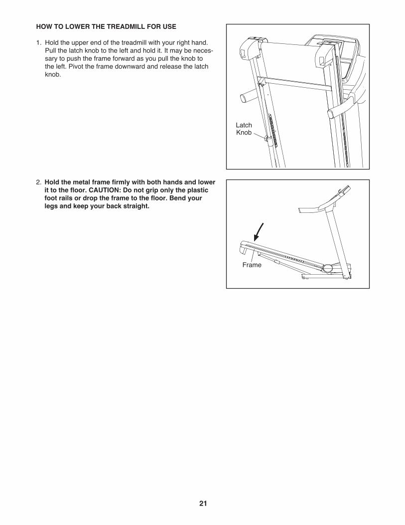
1. Hold the upper end of the treadmill with your right hand.Pull the latch knob to the left and hold it. It may be neces-sary to push the frame forward as you pull the knob tothe left. Pivot the frame downward and release the latchknob.
2. Hold the metal frame firmly with both hands and lowerit to the floor. CAUTION: Do not grip only the plasticfoot rails or drop the frame to the floor. Bend yourlegs and keep your back straight.
LatchKnob
Frame
22
TROUBLESHOOTINGMost treadmill problems can be solved by following the simple steps below. Find the symptom thatapplies, and follow the steps listed. If further assistance is needed, see the front cover of this manual.
PROBLEM: The power does not turn on
SOLUTION: a. Make sure that the power cord is plugged into a surge suppressor, and that the surge suppressoris plugged into a properly grounded outlet (see page 13). Use only a single-outlet surge suppres-sor that meets all of the specifications described on page 13. IMPORTANT: The treadmill is notcompatible with GFCI-equipped outlets.
b. After the power cord has been plugged in, make sure that the key is inserted into the console.
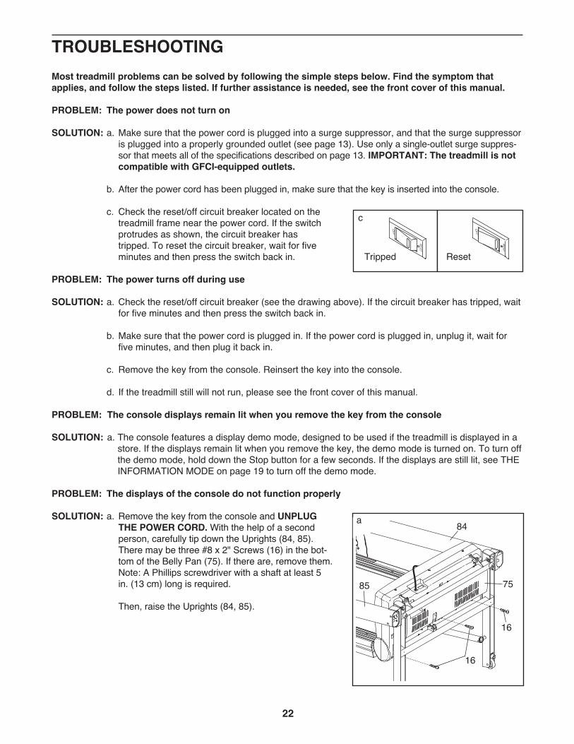
c. Check the reset/off circuit breaker located on thetreadmill frame near the power cord. If the switchprotrudes as shown, the circuit breaker hastripped. To reset the circuit breaker, wait for fiveminutes and then press the switch back in.
PROBLEM: The power turns off during use
SOLUTION: a. Check the reset/off circuit breaker (see the drawing above). If the circuit breaker has tripped, waitfor five minutes and then press the switch back in.
b. Make sure that the power cord is plugged in. If the power cord is plugged in, unplug it, wait forfive minutes, and then plug it back in.
c. Remove the key from the console. Reinsert the key into the console.
d. If the treadmill still will not run, please see the front cover of this manual.
PROBLEM: The console displays remain lit when you remove the key from the console
SOLUTION: a. The console features a display demo mode, designed to be used if the treadmill is displayed in astore. If the displays remain lit when you remove the key, the demo mode is turned on. To turn offthe demo mode, hold down the Stop button for a few seconds. If the displays are still lit, see THEINFORMATION MODE on page 19 to turn off the demo mode.
PROBLEM: The displays of the console do not function properly
SOLUTION: a. Remove the key from the console and UNPLUGTHE POWER CORD. With the help of a secondperson, carefully tip down the Uprights (84, 85).There may be three #8 x 2" Screws (16) in the bot-tom of the Belly Pan (75). If there are, remove them.Note: A Phillips screwdriver with a shaft at least 5in. (13 cm) long is required.
Then, raise the Uprights (84, 85).
Tripped Reset
c
16
16
84
7585
a
23
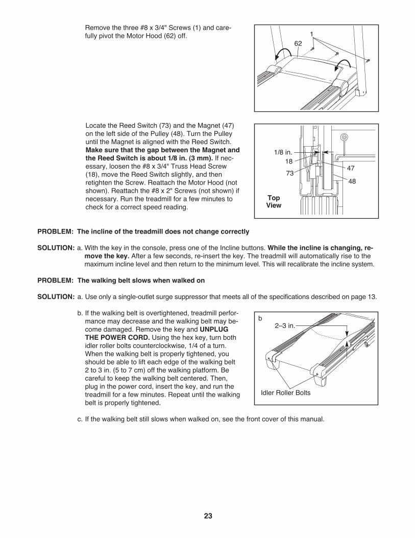
Remove the three #8 x 3/4" Screws (1) and care-fully pivot the Motor Hood (62) off.
Locate the Reed Switch (73) and the Magnet (47)on the left side of the Pulley (48). Turn the Pulleyuntil the Magnet is aligned with the Reed Switch.Make sure that the gap between the Magnet andthe Reed Switch is about 1/8 in. (3 mm). If nec-essary, loosen the #8 x 3/4" Truss Head Screw(18), move the Reed Switch slightly, and thenretighten the Screw. Reattach the Motor Hood (notshown). Reattach the #8 x 2" Screws (not shown) ifnecessary. Run the treadmill for a few minutes tocheck for a correct speed reading.
PROBLEM: The incline of the treadmill does not change correctly
SOLUTION: a. With the key in the console, press one of the Incline buttons. While the incline is changing, re-move the key. After a few seconds, re-insert the key. The treadmill will automatically rise to themaximum incline level and then return to the minimum level. This will recalibrate the incline system.
PROBLEM: The walking belt slows when walked on
SOLUTION: a. Use only a single-outlet surge suppressor that meets all of the specifications described on page 13.
b. If the walking belt is overtightened, treadmill perfor-mance may decrease and the walking belt may be-come damaged. Remove the key and UNPLUGTHE POWER CORD. Using the hex key, turn bothidler roller bolts counterclockwise, 1/4 of a turn.When the walking belt is properly tightened, youshould be able to lift each edge of the walking belt2 to 3 in. (5 to 7 cm) off the walking platform. Becareful to keep the walking belt centered. Then,plug in the power cord, insert the key, and run thetreadmill for a few minutes. Repeat until the walkingbelt is properly tightened.
c. If the walking belt still slows when walked on, see the front cover of this manual.
TopView
471873
1/8 in.
48
Idler Roller Bolts
2–3 in.b
621
24
PROBLEM: The walking belt is off-center or slips when walked on
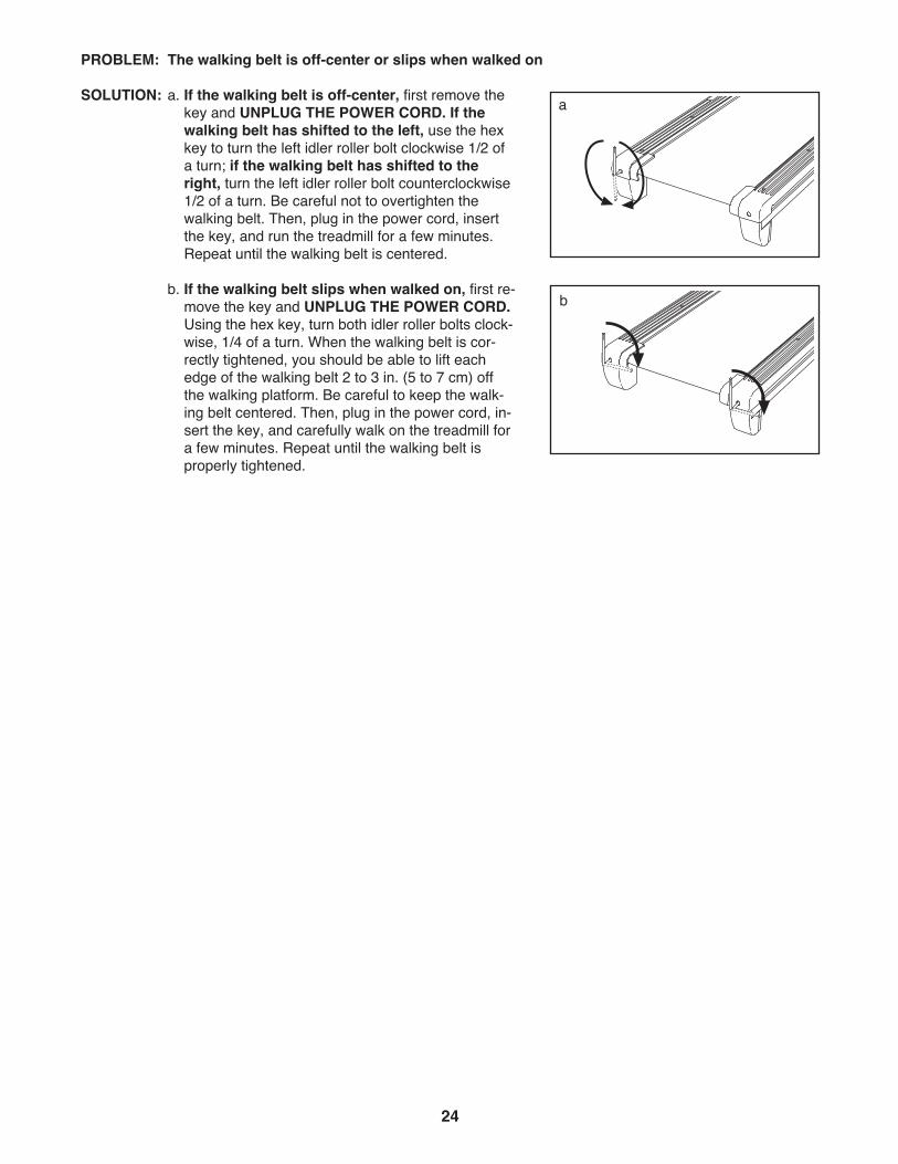
SOLUTION: a. If the walking belt is off-center, first remove thekey and UNPLUG THE POWER CORD. If thewalking belt has shifted to the left, use the hexkey to turn the left idler roller bolt clockwise 1/2 ofa turn; if the walking belt has shifted to theright, turn the left idler roller bolt counterclockwise1/2 of a turn. Be careful not to overtighten thewalking belt. Then, plug in the power cord, insertthe key, and run the treadmill for a few minutes.Repeat until the walking belt is centered.
b. If the walking belt slips when walked on, first re-move the key and UNPLUG THE POWER CORD.Using the hex key, turn both idler roller bolts clock-wise, 1/4 of a turn. When the walking belt is cor-rectly tightened, you should be able to lift eachedge of the walking belt 2 to 3 in. (5 to 7 cm) offthe walking platform. Be careful to keep the walk-ing belt centered. Then, plug in the power cord, in-sert the key, and carefully walk on the treadmill fora few minutes. Repeat until the walking belt isproperly tightened.
a
b
25
These guidelines will help you to plan your exerciseprogram. For detailed exercise information, obtain areputable book or consult your physician. Remember,proper nutrition and adequate rest are essential forsuccessful results.
EXERCISE INTENSITY
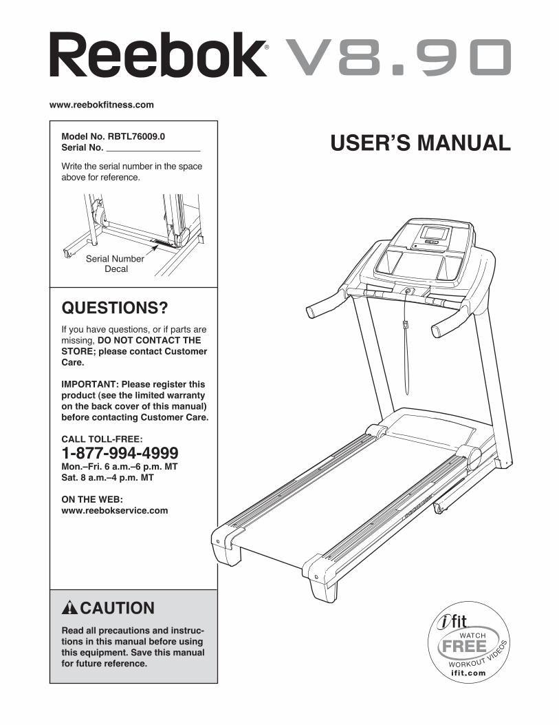
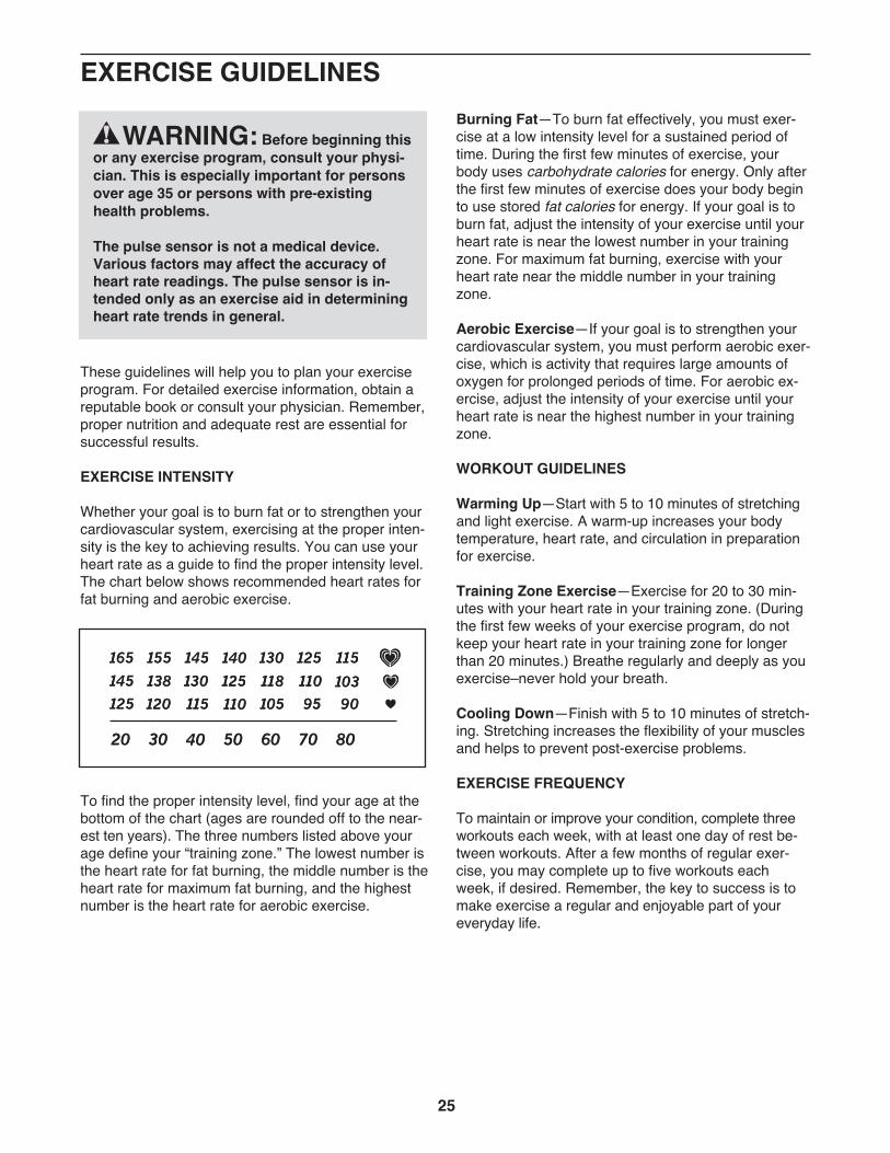
Whether your goal is to burn fat or to strengthen yourcardiovascular system, exercising at the proper inten-sity is the key to achieving results. You can use yourheart rate as a guide to find the proper intensity level.The chart below shows recommended heart rates forfat burning and aerobic exercise.
To find the proper intensity level, find your age at thebottom of the chart (ages are rounded off to the near-est ten years). The three numbers listed above yourage define your “training zone.” The lowest number isthe heart rate for fat burning, the middle number is theheart rate for maximum fat burning, and the highestnumber is the heart rate for aerobic exercise.
Burning Fat—To burn fat effectively, you must exer-cise at a low intensity level for a sustained period oftime. During the first few minutes of exercise, yourbody uses carbohydrate calories for energy. Only afterthe first few minutes of exercise does your body beginto use stored fat calories for energy. If your goal is toburn fat, adjust the intensity of your exercise until yourheart rate is near the lowest number in your trainingzone. For maximum fat burning, exercise with yourheart rate near the middle number in your trainingzone.
Aerobic Exercise—If your goal is to strengthen yourcardiovascular system, you must perform aerobic exer-cise, which is activity that requires large amounts ofoxygen for prolonged periods of time. For aerobic ex-ercise, adjust the intensity of your exercise until yourheart rate is near the highest number in your trainingzone.
WORKOUT GUIDELINES
Warming Up—Start with 5 to 10 minutes of stretchingand light exercise. A warm-up increases your bodytemperature, heart rate, and circulation in preparationfor exercise.
Training Zone Exercise—Exercise for 20 to 30 min-utes with your heart rate in your training zone. (Duringthe first few weeks of your exercise program, do notkeep your heart rate in your training zone for longerthan 20 minutes.) Breathe regularly and deeply as youexercise–never hold your breath.
Cooling Down—Finish with 5 to 10 minutes of stretch-ing. Stretching increases the flexibility of your musclesand helps to prevent post-exercise problems.
EXERCISE FREQUENCY
To maintain or improve your condition, complete threeworkouts each week, with at least one day of rest be-tween workouts. After a few months of regular exer-cise, you may complete up to five workouts eachweek, if desired. Remember, the key to success is tomake exercise a regular and enjoyable part of youreveryday life.
EXERCISE GUIDELINES
WARNING: Before beginning thisor any exercise program, consult your physi-cian. This is especially important for personsover age 35 or persons with pre-existinghealth problems.
The pulse sensor is not a medical device.Various factors may affect the accuracy ofheart rate readings. The pulse sensor is in-tended only as an exercise aid in determiningheart rate trends in general.

26
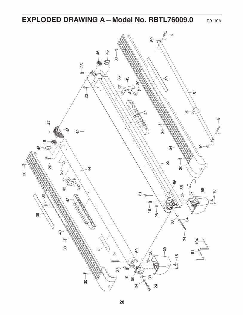
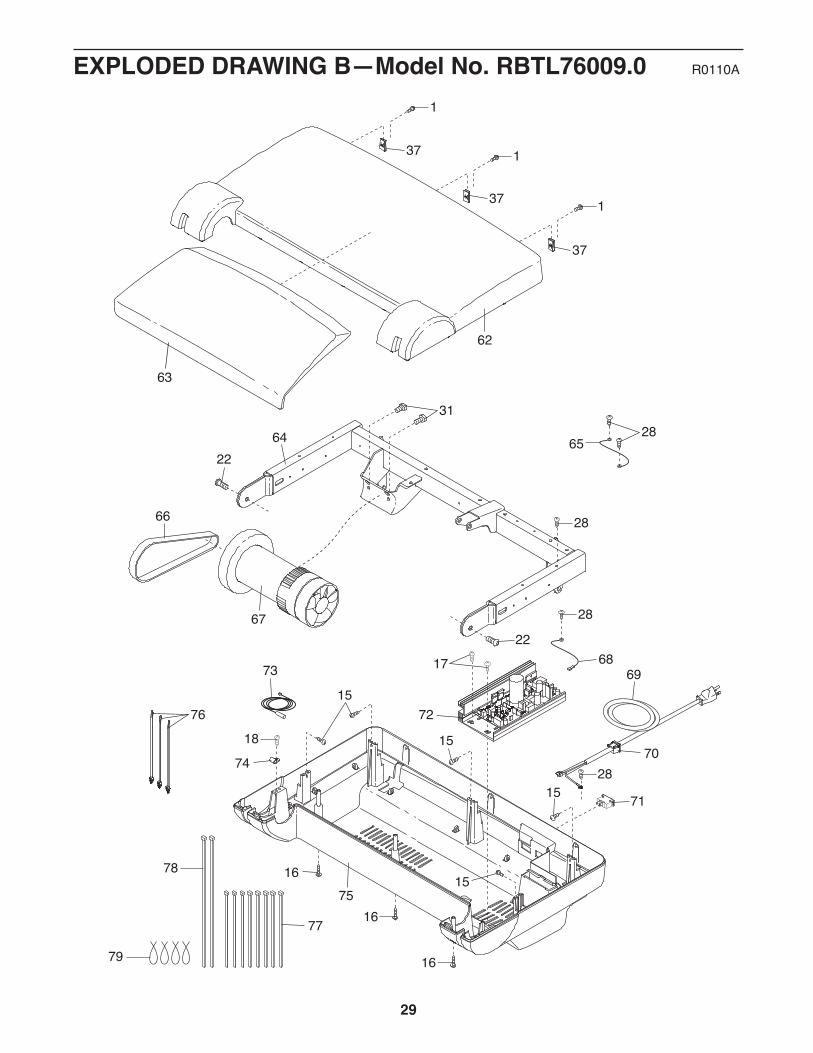
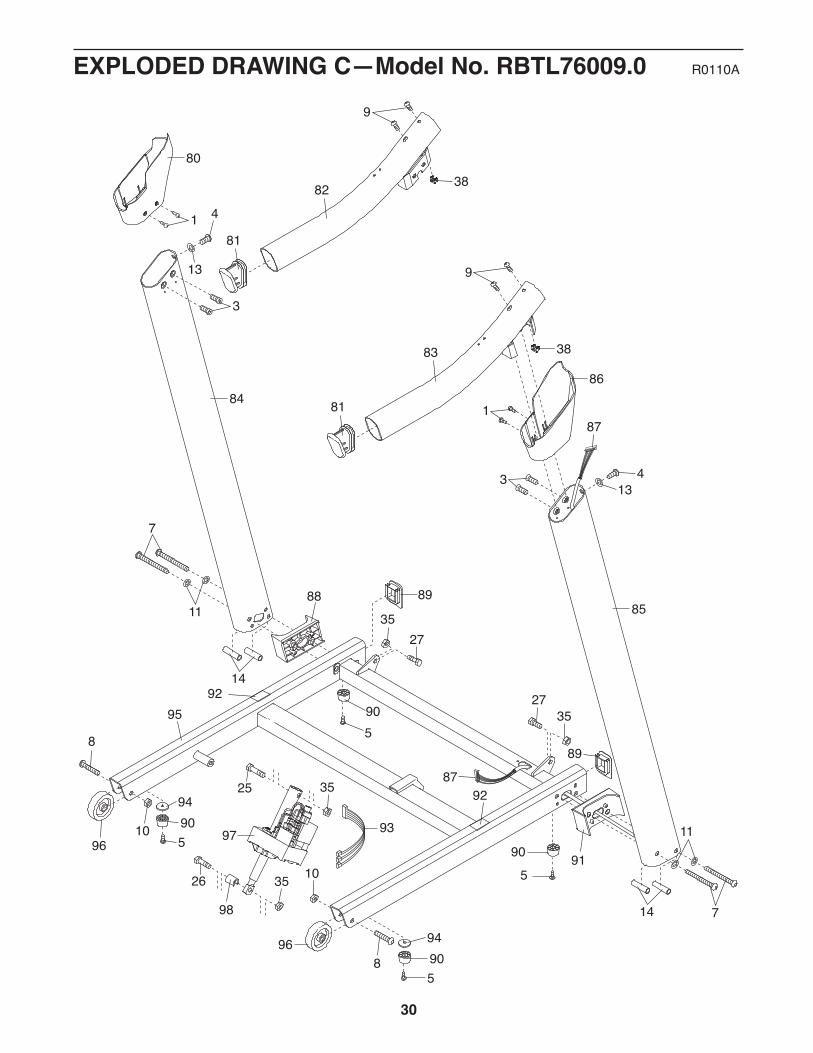
PART LIST—Model No. RBTL76009.0 R0110A
To locate the parts listed below, see the EXPLODED DRAWING near the end of this manual.
Key No. Qty. Description Key No. Qty. Description1 28 #8 x 3/4" Screw2 4 #10 x 3/4" Screw3 4 5/16" x 1" Flat Head Patch Bolt4 2 5/16" x 1" Patch Bolt5 4 #8 x 1" Tek Screw6 1 3/8" x 1 3/4" Patch Bolt7 4 3/8" x 4" Patch Bolt8 3 3/8" x 2" Bolt9 4 1/4" x 1" Patch Bolt10 3 3/8" Nut11 4 3/8" Star Washer12 4 #10 Star Washer13 2 5/16" Star Washer14 4 Bolt Spacer15 5 #8 x 3/4" Tek Screw16 3 #8 x 2" Screw17 8 #8 x 1/2" Pan Head Screw18 5 #8 x 3/4" Truss Head Screw19 2 #8 x 1 1/2" Screw20 2 5/16" x 1 1/2" Bolt21 2 5/16" x 3 5/8" Bolt22 2 3/8" x 1" Patch Bolt23 1 1/4" x 1" Bolt24 2 Idler Roller Bolt25 1 3/8" x 1 3/4" Bolt26 1 3/8" x 1 1/2" Bolt27 2 3/8" x 3/4" Bolt28 7 #8 x 1/2" Bright Screw29 1 #8 x 1/2" Ground Screw30 8 #12 x 1 1/4" Screw31 2 1/4" Motor Bolt32 4 #8 Belt Guide Screw33 2 1/4" Washer34 2 1/4" Split Washer35 4 3/8" Jam Nut36 4 5/16" Flange Nut37 3 Hood Clip38 2 5/16" Cage Nut39 2 Foot Rail Decal40 1 Left Foot Rail41 1 Latch Warning Decal42 2 Platform Cushion43 2 Belt Guide44 1 Walking Platform45 2 Frame Cap46 2 Frame Spacer47 1 Magnet48 1 Front Roller/Pulley49 1 Walking Belt50 1 Latch Cap
51 1 Storage Latch52 1 Latch Knob53 4 #8 x 1" Screw54 1 Right Foot Rail55 1 Frame56 2 Roller Bracket57 1 Roller Ground Wire58 1 Right Rear Foot59 1 Left Rear Foot60 1 Idler Roller61 1 Hex Key62 1 Motor Hood63 1 Hood Accent64 1 Lift Frame65 1 Lift Frame Ground Wire66 1 Drive Motor Belt67 1 Drive Motor68 1 Controller Ground Wire69 1 Power Cord70 1 Grommet71 1 Reset/Off Circuit Breaker72 1 Controller73 1 Reed Switch74 1 Reed Switch Clamp75 1 Belly Pan76 3 Wire Tie77 8 8" Tie78 2 15" Tie79 4 Releasable Tie80 1 Left Upright Cover81 2 Handrail Cap82 1 Left Handrail83 1 Right Handrail84 1 Left Upright85 1 Right Upright86 1 Right Upright Cover87 1 Upright Wire88 1 Left Upright Spacer89 2 Base Cap90 4 Base Foot91 1 Right Upright Spacer92 2 Caution Decal93 1 Incline Wire94 2 Base Foot Spacer95 1 Base96 2 Wheel97 1 Incline Motor98 1 Incline Motor Spacer99 1 Key/Clip100 2 Cable Tie

27
Key No. Qty. Description Key No. Qty. Description101 1 Console102 1 Console Frame103 1 Accessory Tray104 1 5/32" Hex Key105 2 Console Clamp106 1 Console Base107 1 Crossbar108 1 Access Door
109 1 Console Ground Wire110 1 Audio Wire
* – 8" Blue Wire, M/F* – 10" Blue Wire, 2F* – 12" Red Wire, M/F* – 10" Black Wire, M/F* – Userʼs Manual
Note: Specifications are subject to change without notice. For information about ordering replacement parts, seethe back cover of this manual. *These parts are not illustrated.
8
6
52
51
20
21
21
34
33
3433
28
32
3243
43
30
45
30
30
3039
40
36
36
36
47
4546
36
44
41
4948
5439
60
55
56
56
46
58
59 61
50
57 18
10
24
23
18
19
19
20
24
30
30
30
30
28
104
42
42
28
EXPLODED DRAWING A—Model No. RBTL76009.0 R0110A
15
15
15
15
7418
73
37
37
37
1
1
1
17
22
22
28
28
69
70
71
68
62
64
76
75
72
65
16
28
28
31
67
66
77
79
78
16
16
63
EXPLODED DRAWING B—Model No. RBTL76009.0 R0110A
29
905
905
905
96
96
8
7
11
7
11
2735
89
89
85
9592
88
91
92
14
94
905
9425
26
35
35
97
98
87
10
10
8
93
14
87
86
83
82
81
81
80
38
38
1
1
3
3
4
413
13
9
9
2735
84
30
EXPLODED DRAWING C—Model No. RBTL76009.0 R0110A

99
53
1
108
103
101
12
107
12
10929
102
106
11
1
11
122
1
1
171
1
1
100
17
105
105
110
53
17
17
17
1
1
31
EXPLODED DRAWING D—Model No. RBTL76009.0 R0110A

Part No. 292810 R0110A Printed in USA © 2010 ICON IP, Inc.
ORDERING REPLACEMENT PARTSTo order replacement parts, please see the front cover of this manual. To help us assist you, be prepared to pro-vide the following information when contacting us:
• the model number and serial number of the product (see the front cover of this manual)
• the name of the product (see the front cover of this manual)
• the key number and description of the replacement part(s) (see the PART LIST and the EXPLODEDDRAWING near the end of this manual)
ICON Health & Fitness, Inc. (ICON) warrants this product to be free from defects in workmanship andmaterial, under normal use and service conditions. The frame is warranted for a lifetime. The drive motoris warranted for twenty-five (25) years from the date of purchase. Parts and labor are warranted for one(1) year from the date of purchase.
This warranty extends only to the original purchaser. ICONʼs obligation under this warranty is limited torepairing or replacing, at ICONʼs option, the product through one of its authorized service centers. All re-pairs for which warranty claims are made must be preauthorized by ICON. If the product is shipped to aservice center, freight charges to and from the service center will be the customerʼs responsibility. Forreplacement parts shipped while the product is under warranty, the customer will be responsible for aminimal handling charge. For in-home service, the customer will be responsible for a minimal trip charge.This warranty does not extend to any damage to a product caused by or attributable to freight damage,abuse, misuse, improper or abnormal usage, or repairs not provided by an ICON authorized service cen-ter; to products used for commercial or rental purposes or as store display models; or to products trans-ported or purchased outside the US. No other warranty beyond that specifically set forth above is autho-rized by ICON.
ICON is not responsible or liable for indirect, special, or consequential damages arising out of or in con-nection with the use or performance of the product; damages with respect to any economic loss, loss ofproperty, loss of revenues or profits, loss of enjoyment or use, or costs of removal or installation; or otherconsequential damages of whatsoever nature. Some states do not allow the exclusion or limitation of in-cidental or consequential damages. Accordingly, the above limitation may not apply to you.
The warranty extended hereunder is in lieu of any and all other warranties, and any implied warranties ofmerchantability or fitness for a particular purpose are limited in their scope and duration to the terms setforth herein. Some states do not allow limitations on how long an implied warranty lasts. Accordingly, theabove limitation may not apply to you.
This warranty gives you specific legal rights. You may also have other rights that vary from state to state.
ICON Health & Fitness, Inc., 1500 S. 1000 W., Logan, UT 84321-9813
LIMITED WARRANTYIMPORTANT: You must register this product within 30 days of the purchase date to avoid addedfees for service needed under warranty. Go to www.reebokservice.com/registration.