
User’s Manual YVP110 Advanced Valve Positioner · PDF fileUser’s. Manual. YVP110...
161
User’s Manual YVP110 Advanced Valve Positioner IM 21B04C01-01E IM 21B04C01-01E 10th Edition
Transcript of User’s Manual YVP110 Advanced Valve Positioner · PDF fileUser’s. Manual. YVP110...

User’sManual YVP110
Advanced Valve Positioner
IM 21B04C01-01E
IM 21B04C01-01E10th Edition
i
IM 21B04C01-01E
YVP110Advanced Valve Positioner
IM 21B04C01-01E 10th Edition
CONTENTSIntroduction ..........................................................................................................viii
Notes on the User’s Manual ............................................................................. viii
For Safe Use of Product.................................................................................... viii
Warranty ..............................................................................................................ix
Trade Mark ..........................................................................................................ix
ATEX Documentation ...........................................................................................x
PART I: HARDWARE1. Notes on Handling .................................................................................... 1-1
1.1 Nameplate ..........................................................................................................1-11.2 Transport ............................................................................................................1-11.3 Storage ...............................................................................................................1-11.4 Choosing the Installation Location .................................................................1-11.5 Use of a Transceiver .........................................................................................1-11.6 Insulation Resistance Test and Withstand Voltage Test .............................. 1-21.7 Notes for Saftey .................................................................................................1-21.8 EMC Conformity Standards .............................................................................1-31.9 Installation of Explosion Protected Type Positioner .................................... 1-3
1.9.1 FM Certification ..................................................................................1-3
1.9.2 ATEX Certification ..............................................................................1-7
1.9.3 CSA Certification ..............................................................................1-12
1.9.4 TIIS Certification ..............................................................................1-12
2. Part Names ................................................................................................ 2-12.1 Appearance and Part Names ...........................................................................2-12.2 Block Diagram ...................................................................................................2-1
3. Installing YVP110 on Actuator ................................................................ 3-13.1 General ...............................................................................................................3-13.2 Installing YVP110 on Actuator .........................................................................3-1
3.2.1 Installing YVP110 on Linear-motion Control Valve ............................ 3-1
3.2.2 Installing YVP110 on Rotary-motion Control Valve ........................... 3-3
3.2.3 A/M Switching ....................................................................................3-5
10th Edition: Dec. 2013 (YK)All Rights Reserved, Copyright © 2000, Yokogawa Electric Corporation
ii
IM 21B04C01-01E
4. Wiring and Piping ..................................................................................... 4-14.1 General ...............................................................................................................4-14.2 Piping .................................................................................................................4-1
4.2.1 Air Supply ...........................................................................................4-1
4.2.2 Pneumatic Piping ...............................................................................4-1
4.3 Wiring .................................................................................................................4-24.3.1 Recommended Cables ......................................................................4-2
4.3.2 Precautions on Wiring ........................................................................4-2
4.4 Grounding ..........................................................................................................4-4
5. Setup .......................................................................................................... 5-15.1 General ...............................................................................................................5-15.2 Setting Basic Parameters ................................................................................5-15.3 Carrying out Tuning .........................................................................................5-25.4 Checking Valve Actions ...................................................................................5-45.5 Setting Parameters of Transducer Block .......................................................5-4
6. Maintenance .............................................................................................. 6-16.1 General ...............................................................................................................6-16.2 Periodic Inspections .........................................................................................6-1
6.2.1 Cleaning the Fixed Nozzle .................................................................6-1
6.3 Part Replacement ..............................................................................................6-26.3.1 Replacing the Control Relay Assembly ............................................. 6-2
6.3.2 Replacing the Screen Filters .............................................................6-2
6.3.3 Replacing the Internal Air Filter ..........................................................6-2
6.3.4 Tuning the Pressure Balance of Control Relay ................................. 6-3
7. Standard Specifications .......................................................................... 7-1
PART II: FUNCTIONS8. About Fieldbus ......................................................................................... 8-1
8.1 Outline ................................................................................................................8-18.2 Internal Structure of YVP110 ............................................................................8-1
8.2.1 System/network Management VFD .................................................. 8-1
8.2.2 Function Block VFD ...........................................................................8-1
8.3 Logical Structure of Each Block .....................................................................8-18.4 System Configuration ......................................................................................8-1
8.4.1 Connection of Devices .......................................................................8-2
8.5 Integration of DD ...............................................................................................8-2
9. Configuration ............................................................................................ 9-19.1 Network Design .................................................................................................9-19.2 Network Definition ............................................................................................9-19.3 Definition of Combining Function Blocks ......................................................9-2
iii
IM 21B04C01-01E
9.4 Setting of Tags and Addresses .......................................................................9-39.5 Communication Setting ...................................................................................9-4
9.5.1 VCR Setting .......................................................................................9-4
9.5.2 Function Block Execution Control ...................................................... 9-4
9.6 Block Setting .....................................................................................................9-59.6.1 Link Object .........................................................................................9-5
9.6.2 Trend Object ......................................................................................9-5
9.6.3 View Object ........................................................................................9-5
9.6.4 Function Block Parameters..............................................................9-12
10. Actions of YVP110 During Operation ................................................... 10-110.1 Block Modes ....................................................................................................10-110.2 Alarm Generation ............................................................................................10-210.3 Simulation Function .......................................................................................10-3
11. Resource Block ..................................................................................... 11-111.1 General ............................................................................................................ 11-111.2 Alarm Processing .......................................................................................... 11-111.3 Device Status .................................................................................................. 11-1
12. Transducer Block ................................................................................... 12-112.1 General .............................................................................................................12-112.2 Forward Path ...................................................................................................12-1
12.2.1 Input from AO Block .........................................................................12-1
12.2.2 Position-to-flow Rate Characteristic Conversion .............................12-2
12.2.3 FINAL_VALUE and Range ..............................................................12-2
12.2.4 Tight-shut and Full-open Actions .....................................................12-2
12.3 Backward Path ................................................................................................12-212.3.1 FINAL_POSITION_VALUE .............................................................12-2
12.3.2 Limit Switches ..................................................................................12-2
12.4 Auto Tuning .....................................................................................................12-312.5 Travel Calibration ............................................................................................12-412.6 Online Diagnostics .........................................................................................12-4
12.6.1 XD_ERROR .....................................................................................12-4
12.6.2 Fail-safe Action.................................................................................12-5
12.6.3 Operation Result Integration ...........................................................12-5
12.6.4 Recording of Revisions ...................................................................12-5
12.7 Control Parameters .........................................................................................12-512.8 Temperature and Pressure Measurement ....................................................12-5
13. AO Function Block ................................................................................. 13-113.1 General .............................................................................................................13-113.2 Modes ...............................................................................................................13-113.3 Forward Path ...................................................................................................13-1
13.3.1 Fault state ........................................................................................13-1
13.4 Backward Path ................................................................................................13-2
iv
IM 21B04C01-01E
13.5 IO_OPTS and STATUS_OPTS ........................................................................13-213.6 Mode Shedding upon Computer Failure .....................................................13-313.7 Initialization at Start ........................................................................................13-313.8 Alarm Processing ..........................................................................................13-3
14. DI Function Block .................................................................................. 14-114.1 General .............................................................................................................14-114.2 Modes ...............................................................................................................14-114.3 PV Value (PV_D) ..............................................................................................14-114.4 Filtering ............................................................................................................14-114.5 Output ...............................................................................................................14-214.6 IO_OPTS and STATUS_OPTS ........................................................................14-214.7 Alarm Processing ..........................................................................................14-2
14.7.1 Block Alarms ....................................................................................14-2
14.7.2 Discrete Alarm ..................................................................................14-2
15. OS Function Block ................................................................................. 15-115.1 General .............................................................................................................15-115.2 Modes ...............................................................................................................15-115.3 Output Processing ..........................................................................................15-115.4 Backward Path (BKCAL_OUT) .....................................................................15-215.5 STATUS_OPTS ...............................................................................................15-215.6 Alarm Processing ..........................................................................................15-2
16. PID Function Block ................................................................................ 16-116.1 General .............................................................................................................16-116.2 Modes ...............................................................................................................16-116.3 Input Processing .............................................................................................16-116.4 Setpoint (SP) Limiters ....................................................................................16-116.5 PID Computation .............................................................................................16-216.6 Control Output .................................................................................................16-216.7 Direction of Control Action ............................................................................16-216.8 Control Action Bypass ...................................................................................16-216.9 Feed-forward ...................................................................................................16-316.10 External-output Tracking (LO) .......................................................................16-316.11 Measured-value Tracking ...............................................................................16-316.12 CONTROL_OPTS ............................................................................................16-316.13 Initialization and Manual Fallback (IMan) .....................................................16-416.14 Manual Fallback ..............................................................................................16-4
16.14.1 STATUS_OPTS ...............................................................................16-4
16.15 Auto Fallback ...................................................................................................16-416.16 Mode Shedding upon Computer Failure ......................................................16-416.17 Alarms ..............................................................................................................16-5
16.17.1 Block Alarm (BLOCK_ALM) .............................................................16-5
16.17.2 Process Alarms ................................................................................16-5
v
IM 21B04C01-01E
17. IS Function Block ................................................................................... 17-117.1 IS Function Block Schematic ........................................................................17-117.2 Input Section ...................................................................................................17-3
17.2.1 Mode Handling ................................................................................17-3
17.2.2 MIN_GOOD Handling .....................................................................17-3
17.3 Selection .........................................................................................................17-417.3.1 OP_SELECT Handling ...................................................................17-4
17.3.2 SELECTION Handling ....................................................................17-5
17.4 Output Processing ....................................................................................... 17-1117.4.1 Handling of SELECTED ................................................................ 17-11
17.4.2 OUT Processing ............................................................................17-12
17.4.3 STATUS_OPTS ............................................................................17-13
17.5 Application Example ....................................................................................17-13
18. AR Function Block ................................................................................. 18-118.1 AR Function Block Schematic ......................................................................18-118.2 Input Section ...................................................................................................18-2
18.2.1 Main Inputs ......................................................................................18-2
18.2.2 Auxiliary Inputs ................................................................................18-2
18.2.3 INPUT_OPTS .................................................................................18-3
18.2.4 Relationship between the Main Inputs and PV ...............................18-3
18.3 Computation Section .....................................................................................18-318.3.1 Computing Equations .....................................................................18-3
18.3.2 Compensated Values ......................................................................18-4
18.3.3 Average Calculation ........................................................................18-4
18.4 Output Section ...............................................................................................18-418.4.1 Mode Handling ................................................................................18-4
18.4.2 Status Handling ...............................................................................18-5
19. Diagnostics ............................................................................................. 19-119.1 Overview ..........................................................................................................19-119.2 Integration Functions .....................................................................................19-119.3 Signature Measurement Functions ..............................................................19-2
19.3.1 Signature Measurement Procedure ................................................19-2
19.3.2 Signatures and Relevant Parameters .............................................19-3
19.3.3 Signature Measuring Result ............................................................19-4
20. Troubleshooting ..................................................................................... 20-120.1 What to Do First ...............................................................................................20-120.2 Troubleshooting Communications ...............................................................20-120.3 Troubleshooting Function Block Parameters .............................................20-120.4 Troubleshooting Valve Control .....................................................................20-220.5 Troubleshooting Auto Tuning ........................................................................20-320.6 Troubleshooting Position, Pressure, and Temperature Sensors ..............20-3
vi
IM 21B04C01-01E
Appendix 1. Function Block Parameters ......................................................A-1A1.1 Parameters of Resource Block ...................................................................... A-1A1.2 Parameters of Transducer Block ................................................................... A-3A1.3 Parameters of AO Block ................................................................................. A-8A1.4 Parameters of DI Block ................................................................................. A-10A1.5 Parameters of OS Block ................................................................................A-11A1.6 Parameters of PID Block (Optional) ............................................................ A-12A1.7 Parameters of IS Block .................................................................................. A-14A1.8 Parameters of AR Block ................................................................................ A-16A1.9 IO_OPTS - Availability of Options for Each Block ..................................... A-18A1.10 STATUS_OPTS - Availability of Options for Each Block ........................... A-18A1.11 CONTROL_OPTS - Availability of Options for Each Block ...................... A-18
Appendix 2. Link Master Functions .............................................................A-19A2.1 Link Active Scheduler.................................................................................... A-19A2.2 Link Master ..................................................................................................... A-19A2.3 Transfer of LAS .............................................................................................. A-19A2.4 LM Functions .................................................................................................. A-20A2.5 LM Parameters ............................................................................................... A-21
A2.5.1 LM Parameter List ............................................................................A-21
A2.5.2 Descriptions for LM Parameters ......................................................A-22
A2.6 FAQs ................................................................................................................ A-25
Appendix 3. DD Methods and DD Menu ......................................................A-26A3.1 Overview ......................................................................................................... A-26A3.2 DD Methods ................................................................................................... A-26
A3.2.1 Transducer Block .............................................................................A-26
A3.2.2 AO Block ..........................................................................................A-28
A3.2.3 OS Block ..........................................................................................A-29
Appendix 4. Software Download ..................................................................A-30A4.1 Benefits of Software Download .................................................................... A-30A4.2 Specifications ................................................................................................. A-30A4.3 Preparations for Software Downloading ..................................................... A-30A4.4 Software Download Sequence ..................................................................... A-30A4.5 Download Files ............................................................................................... A-31A4.6 Steps after Activating a Field Device ........................................................... A-31A4.7 Troubleshooting ............................................................................................. A-32A4.8 Resource Block’s Parameters Relating to Software Download ............... A-32A4.9 System/Network Management VFD Parameters Relating to Software
Download ........................................................................................................ A-34A4.10 Comments on System/Network Management VFD Parameters Relating to
Software Download ....................................................................................... A-35
Appendix 5. Position Adjustment of Feedback Lever ...............................A-37

vii
IM 21B04C01-01E
Appendix 6. Manual Tuning Guideline ........................................................A-38A6.1 General ............................................................................................................ A-38A6.2 Control Parameter Tuning Procedure.......................................................... A-38A6.3 Examples of Tuning Control Parameters .................................................... A-40A6.4 Description of Control Parameters .............................................................. A-41
Installation and Operating Precautions for TIIS Flameproof Equipment .............................................................................................................EX-B03
Customer Maintenance Parts ListYVP110 Advanced Valve Positioner ................................................ CMPL21B04C01-01E
Revision Record
<Introduction> viii
IM 21B04C01-01E
IntroductionThe YVP110 advanced valve positioner is fully factory-tested according to the specifications indicated upon the order.
This User’s Manual consists of two parts: Hardware and Functions. The Hardware part gives instructions on handling, wiring set-up and maintenance of YVP110, and the Functions part describes the software functions of YVP110.
In order for the YVP110 to be fully functional and to operate in an efficient manner, both parts in this manual must be carefully read, so that users become familiar with the functions, operation, and handling of the YVP110.
Notes on the User’s Manual• This manual should be delivered to the end
user.• The information contained in this manual is
subject to change without prior notice.• The information contained in this manual, in
whole or part, shall not be transcribed or copied without notice.
• In no case does this manual guarantee the merchantability of the instrument or its adaptability to a specific client need.
• Should any doubt or error be found in this manual, submit inquiries to your local dealer.
• No special specifications are contained in this manual.
• Changes to specifications, structure, and components used may not lead to the revision of this manual unless such changes affect the function and performance of the instrument.
• Some of the diagrams in this instruction manual are partially omitted, described in writing, or simplified for ease of explanation. The drawings contained in the instruction manual may have a position or characters (upper/lower case) that differ slightly from the what are actually seen to an extent that does not hinder the understanding of functions or monitoring of operation.
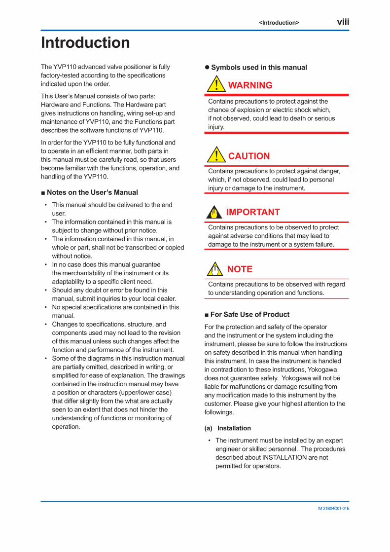
l Symbols used in this manual
WARNING
Contains precautions to protect against the chance of explosion or electric shock which, if not observed, could lead to death or serious injury.
CAUTIONContains precautions to protect against danger, which, if not observed, could lead to personal injury or damage to the instrument.
IMPORTANTContains precautions to be observed to protect against adverse conditions that may lead to damage to the instrument or a system failure.
NOTEContains precautions to be observed with regard to understanding operation and functions.
For Safe Use of ProductFor the protection and safety of the operator and the instrument or the system including the instrument, please be sure to follow the instructions on safety described in this manual when handling this instrument. In case the instrument is handled in contradiction to these instructions, Yokogawa does not guarantee safety. Yokogawa will not be liable for malfunctions or damage resulting from any modification made to this instrument by the customer. Please give your highest attention to the followings.
(a) Installation
• The instrument must be installed by an expert engineer or skilled personnel. The procedures described about INSTALLATION are not permitted for operators.
<Introduction> ix
IM 21B04C01-01E
• Some of the operations will stroke the valve. Keep clear of the valve while the positioner is pneumatically or electrically supplied, so as not to be hit by unexpected movements of the valve.
• In case where ambient temperature is high, care should be taken not to burn yourself, because the surface of the body of the instrument reaches a high temperature.
• All installation shall comply with local installation requirement and local electrical codes.
• Do not supply air at a pressure exceeding the maximum rated air supply pressure. Doing so may result in a high risk of damage or cause an accident.
• To avoid injury or the process being affected when installing or replacing a positioner on a control valve, ensure that; 1) All inputs to the valve actuator and other
accessories of the valve and actuator, including air supply and electrical signal, are cut off;
2) The process has been shut down or the control valve is isolated from the process by using bypass valves or the like; and
3) No pressure remains in the valve actuator.• Auto-Manual switch must not be moved by
anyone except for the authorized engineer.
(b) Wiring
• The instrument must be installed by an expert engineer or skilled personnel. The procedures described about WIRING are not permitted for operators.
• Please confirm voltages between the power supply and the instrument before connecting the power cables and that the cables are not powered before connecting.
(c) Operation
• Wait three minutes after power is turned off, before opening the covers.
(d) Maintenance
• Only the procedures written in maintenance descriptions are allowed for users. When further maintenance is needed, please contact nearest YOKOGAWA office.
• Care should be taken to prevent the build up of drift, dust or other material on the data plate. In case of its maintenance, use clean, soft and dry cloth.
• The instrument modification or parts
replacement for explosion-protected type instruments by other than authorized representative of Yokogawa Electric Corporation is prohibited and will void the approval.
Warranty• The warranty period of the instrument is written
on the estimate sheet that is included with your purchase. Any trouble arising during the warranty period shall be repaired free of charge.
• Inquiries with regard to problems with the instrument shall be accepted by the sales outlet or our local dealer representative.
• Should the instrument be found to be defective, inform us of the model name and the serial number of the instrument together with a detailed description of nonconformance and a progress report. Outline drawings or related data will also be helpful for repair.
• Whether or not the defective instrument is repaired free of charge depends on the result of our inspection.
l The following conditions shall not be eligible for charge-exempt repair.
• Problems caused by improper or insufficient maintenance on the part of the customer.
• Trouble or damage caused by mishandling, misusage, or storage that exceeds the design or specification requirements.
• Problems caused by improper installation location or by maintenance conducted in a non-conforming location.
• Trouble or damage was caused by modification or repair that was handled by a party or parties other than our consigned agent.
• Trouble or damage was caused by inappropriate relocation following delivery.
• Trouble or damage was caused by fire, earthquake, wind or flood damage, lightning strikes or other acts of God that are not directly a result of problems with this instrument.
Trade Mark• FOUNDATION Fieldbus is a trademark of the
Fieldbus Foundation. • Registered trademarks or trademarks
appearing in this manual are not designated by a TM or ® symbol.
• Other company names and product names used in this manual are the registered trademarks or trademarks of their respective owners.
<Introduction> x
IM 21B04C01-01E
ATEX DocumentationThis procedure is only applicable to the countries in European Union.
GB
DK
I
E
NL
SF
P
F
D
S
LT
LV
PL
EST
SLO
H
BG
RO
M
CZ
SK
GR
<1. Notes on Handling> 1-1
IM 21B04C01-01E
1. Notes on HandlingThe YVP110 advanced valve positioner is fully factory-tested upon shipment. When the YVP110 is delivered, visually check that no damage occured during the shipment.
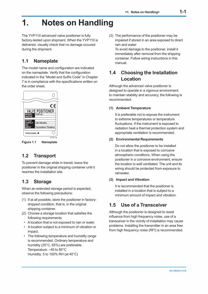
1.1 NameplateThe model name and configuration are indicated on the nameplate. Verify that the configuration indicated in the “Model and Suffix Code” in Chapter 7 is in compliance with the specifications written on the order sheet.
F0101.ai
Figure 1.1 Nameplate
1.2 TransportTo prevent damage while in transit, leave the positioner in the original shipping container until it reaches the installation site.
1.3 StorageWhen an extended storage period is expected, observe the following precautions:
(1) If at all possible, store the positioner in factory-shipped condition, that is, in the original shipping container.
(2) Choose a storage location that satisfies the following requirements.
• A location that is not exposed to rain or water.• A location subject to a minimum of vibration or
impact.• The following temperature and humidity range
is recommended. Ordinary temperature and humidity (25°C, 65%) are preferable.
Temperature: –40 to 85°C Humidity: 5 to 100% RH (at 40°C)
(3) The performance of the positioner may be impaired if stored in an area exposed to direct rain and water.
To avoid damage to the positioner, install it immediately after removal from the shipping container. Follow wiring instructions in this manual.
1.4 Choosing the Installation Location
Although the advanced valve positioner is designed to operate in a vigorous environment, to maintain stability and accuracy, the following is recommended:
(1) Ambient Temperature
It is preferable not to expose the instrument to extreme temperatures or temperature fluctuations. If the instrument is exposed to radiation heat a thermal protection system and appropriate ventilation is recommended.
(2) Environmental Requirements
Do not allow the positioner to be installed in a location that is exposed to corrosive atmospheric conditions. When using the positioner in a corrosive environment, ensure the location is well ventilated. The unit and its wiring should be protected from exposure to rainwater.
(3) Impact and Vibration
It is recommended that the positioner is installed in a location that is subject to a minimum amount of impact and vibration.
1.5 Use of a TransceiverAlthough the positioner is designed to resist influence from high frequency noise, use of a transceiver in the vicinity of installation may cause problems. Installing the transmitter in an area free from high frequency noise (RFI) is recommended.
<1. Notes on Handling> 1-2
IM 21B04C01-01E
1.6 Insulation Resistance Test and Withstand Voltage Test
CAUTION(1) Overvoltage of the test voltage that is so
small that it does not cause an dielectric breakdown may in fact deteriorate insulation and lower the safety performance; to prevent this it is recommended that the amount of testing be kept to a minimum.
(2) The voltage for the insulation resistance test must be 500V DC or lower, and the voltage for the withstand voltage test must be 500V AC or lower. Failure to heed these guidelines may cause faulty operation.
(3) Where a built-in arrester is provided (suffix code: /A), the voltage for the insulation resistance test must be 100V DC or lower, and the voltage for the withstand voltage test must be 100V AC or lower. Failure to heed these guidelines may cause faulty operation.
Follow the steps below to perform the test, the wiring of the communication line must be removed before initiating testing.
Insulation resistance test procedure
1. Lay transition wiring between the + terminal and the − terminal.
2. Connect the insulation resistance meter (with the power turned OFF) between the transition wiring of Step 1 above and ground terminal. The polarity of the input terminals must be positive and that of the ground must be negative.
3. Turn the power of the insulation resistance meter ON and measure the insulation resistance. The duration of the applied voltage must be the period during which 100 MΩ or more is confirmed (or 20 MΩ if the unit is equipped with a built-in arrester).
4. Upon completion of the test, remove the insulation resistance meter, connect a 100 kΩ resistor between the transition wiring, and allow the electricity to discharge. Do not touch the terminal with your bare hands while the electricity is discharging for more than one second.
Withstand voltage test procedure
Testing between the input terminals and the grounding terminal1. Lay the transition wiring between the + terminal
and the − terminal, and connect the withstand voltage tester (with the power turned OFF) between the transition wiring and the grounding terminal. Connect the grounding side of the withstand voltage tester to the grounding terminal.
2. After setting the current limit value of the withstand voltage tester to 10 mA, turn the power ON, and gradually increase the impressed voltage from 0 V to the specified value.
3. The voltage at the specified value must remain for a duration of one minute.
4. Upon completion of the test, carefully reduce the voltage so that no voltage surge occurs.
1.7 Notes for Saftey
CAUTIONWhen air is supplied to a valve, do not touch the moving part (a stem of the valve), as it may suddently move.
CAUTION• While A/M selection switch is set to manual
side (M), the pressure set in the regulator for air supply will be directly output to the actuator regardless of the control signal. Before changing the mode from auto to manual, check and confirm thoroughly that there will be no effect which may cause a danger in process or personal injury by changing the mode.
• Do not change the mode by using auto/manual switch during the operation. If the mode is changed from auto to manual or manual to auto, the valve stem will happnen to move to the position which is different from the control signal (the input signal to the positioner), and thus dangerous.
• As soon as the manual operation is finished, make it sure to change the mode to auto by moving the A/M selection switch to Auto(A) side.
<1. Notes on Handling> 1-3
IM 21B04C01-01E
1.8 EMC Conformity StandardsEN61326-1 Class A, Table 2 (For use in industrial locations)
CAUTIONThis instrument is a Class A product, and it is designed for use in the industrial environment. Please use this instrument in the industrial environment only.
1.9 Installation of Explosion Protected Type Positioner
CAUTIONTo preserve the safety of explosionproof equipment requires great care during mounting, wiring and piping. Safety requirements also place restrictions on maintenance and repair activities. Please read the following section very carefully.
1.9.1 FM Certification
A) FM Intrinsically Safe Type
Cautions for FM Intrinsically safe type. (Following cotents refer “Doc No. IFM017-A12 P.1, 1-1, 2, 2-1, and 2-2.”)
Note 1. Model YVP110 Advenced Valve Positioner with optional code /FS15 are applicable for use in hazardous locations.
• Applicable standard: FM3600, FM3610, FM3611, FM3810, ANSI/NEMA250
• Intrinsically safe, with FISCO parameters, for use in Class I, II, III, Division 1, Groups A, B, C, D, E, F, G and Class I, Zone 0, AEx ia IIC
• Non-incendive for Class I, Division 2, Groups A, B, C, D and Class I, Zone 2, Group IIC
• Indoor/Outdoor hazardous locations, NEMA 4X
• Ambient Temperature: –40 to 60°C
Note 2. Electrical DataRating 1For Groups A, B, C, D, E, F and G or Group IICMaximum Input Voltage Vmax: 24 V Maximum Input Current Imax: 250 mAMaximum Input Power Pmax: 1.2 WMaximum Internal Capacitance Ci: 1.76 nFMaximum Internal Inductance Li: 0 µH
orRating 2For Groups A, B, C, D, E, F and G or Group IICMaximum Input Voltage Vmax: 17.5 VMaximum Input Current Imax: 360 mAMaximum Input Power Pmax: 2.52 WMaximum Internal Capacitance Ci: 1.76 nFMaximum Internal Inductance Li: 0 µH
orRating 3For Groups C, D, E, F and G or Group IIBMaximum Input Voltage Vmax: 17.5 VMaximum Input Current Imax: 380 mAMaximum Input Power Pmax: 5.32 WMaximum Internal Capacitance Ci: 1.76 nFMaximum Internal Inductance Li: 0 µH
• In the rating 1, the output current of the barrier must be limited by a resistor “Ra” such that Io = Uo/Ra.
• In the rating 2 or 3, the output characteristics of the barrier must be the type of trapezoid which are certified as the FISCO model.
• The safety barrier may include a terminator.• More than one field instruments may be
connected to the power supply line.
Note 3. Installation• Dust-tight conduit seal must be used
when installed in Class II and Class III environments.
• Control equipment connected to the Assoiciated Apparatus must not use or generate more than 250 Vrms or Vdc.
• Installation should be in accordance with ANSI/ISA RP12.6 “Installation of Intrinsically Safe Systems for Hazardous (Classified) Locations” and the National Electrical Code (ANSI/NFPA 70) Sections 504 and 505.
• The configuration of Associated Apparatus must be Factory Mutual Research Approved under FISCO Concept.
• Associated Apparatus manufacturer’s installation drawing must be followed when installing this equipment.
• The YVP series are approved for Class I, Zone 0, applications. If connecting AEx[ib] associated Apparatus or AEx ib I.S. Apparatus to the YVP series the I.S. circuit is only suitable for Class I, Zone 1, or Class I, Zone 2, and is not suitable for Class I, Zone 0, or Class I, Division 1, Hazardous (Classified) Locations.
<1. Notes on Handling> 1-4
IM 21B04C01-01E
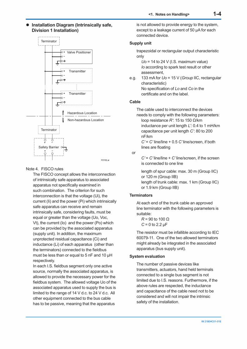
l Installation Diagram (Intrinsically safe, Division 1 Installation)
F0102.ai
Terminator
Valve Positioner
Safety Barrier
Terminator
+−
Transmitter+−
Transmitter+−
−+
Hazardous Location
Non-hazardous Location
−+
Note 4. FISCO rulesThe FISCO concept allows the interconnection of intrinsically safe apparatus to associated apparatus not specifically examined in such combination. The criterion for such interconnection is that the voltage (Ui), the current (Ii) and the power (Pi) which intrinsically safe apparatus can receive and remain intrinsically safe, considering faults, must be equal or greater than the voltage (Uo, Voc, Vt), the current (Io) and the power (Po) which can be provided by the associated apparatus (supply unit). In addition, the maximum unprotected residual capacitance (Ci) and inductance (Li) of each apparatus (other than the terminators) connected to the fieldbus must be less than or equal to 5 nF and 10 µH respectively.In each I.S. fieldbus segment only one active source, normally the associated apparatus, is allowed to provide the necessary power for the fieldbus system. The allowed voltage Uo of the associated apparatus used to supply the bus is limited to the range of 14 V d.c. to 24 V d.c. All other equipment connected to the bus cable has to be passive, meaning that the apparatus
is not allowed to provide energy to the system, except to a leakage current of 50 µA for each connected device.
Supply unit
trapezoidal or rectangular output characteristic only Uo = 14 to 24 V (I.S. maximum value) Io according to spark test result or other
assessment, e.g. 133 mA for Uo = 15 V (Group IIC, rectangular
characteristic) No specification of Lo and Co in the
certificate and on the label.
Cable
The cable used to interconnect the devices needs to comply with the following parameters: loop resistance R’: 15 to 150 Ω/km inductance per unit length L’: 0.4 to 1 mH/km capacitance per unit length C’: 80 to 200
nF/km C’ = C’ line/line + 0.5 C’ line/screen, if both
lines are floatingor
C’ = C’ line/line + C’ line/screen, if the screen is connected to one line
length of spur cable: max. 30 m (Group IIC) or 120 m (Group IIB)
length of trunk cable: max. 1 km (Group IIC) or 1.9 km (Group IIB)
Terminators
At each end of the trunk cable an approved line terminator with the following parameters is suitable: R = 90 to 100 Ω C = 0 to 2.2 µF
The resistor must be infallible according to IEC 60079-11. One of the two allowed terminators might already be integrated in the associated apparatus (bus supply unit).
System evaluation
The number of passive devices like transmitters, actuators, hand held terminals connected to a single bus segment is not limited due to I.S. reasons. Furthermore, if the above rules are respected, the inductance and capacitance of the cable need not to be considered and will not impair the intrinsic safety of the installation.
<1. Notes on Handling> 1-5
IM 21B04C01-01E
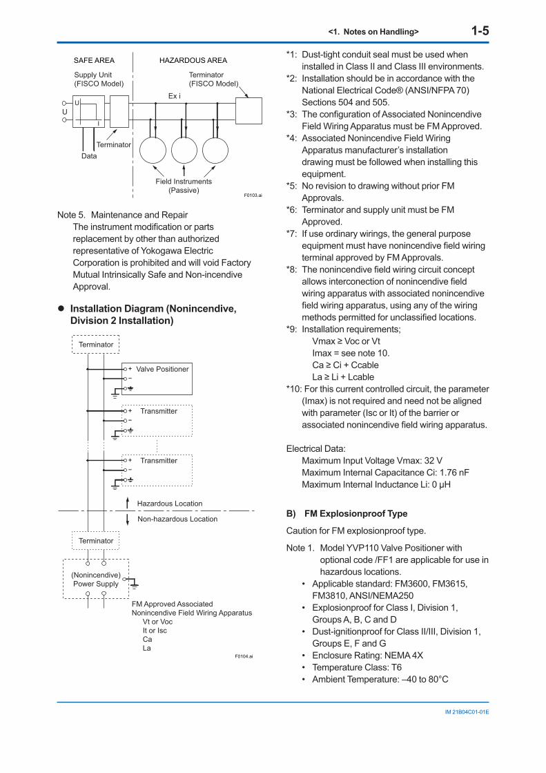
SAFE AREA HAZARDOUS AREA
F0103.ai
Terminator(FISCO Model)
Ex i
Field Instruments(Passive)
Supply Unit(FISCO Model)
TerminatorData
UU
I
Note 5. Maintenance and RepairThe instrument modification or parts replacement by other than authorized representative of Yokogawa Electric Corporation is prohibited and will void Factory Mutual Intrinsically Safe and Non-incendive Approval.
l Installation Diagram (Nonincendive, Division 2 Installation)
F0104.ai
Terminator
Valve Positioner
Terminator
+−
Transmitter+−
Transmitter+−
Hazardous Location
Non-hazardous Location
FM Approved Associated Nonincendive Field Wiring Apparatus
Vt or VocIt or IscCaLa
(Nonincendive)Power Supply
*1: Dust-tight conduit seal must be used when installed in Class II and Class III environments.
*2: Installation should be in accordance with the National Electrical Code® (ANSI/NFPA 70) Sections 504 and 505.
*3: The configuration of Associated Nonincendive Field Wiring Apparatus must be FM Approved.
*4: Associated Nonincendive Field Wiring Apparatus manufacturer’s installation drawing must be followed when installing this equipment.
*5: No revision to drawing without prior FM Approvals.
*6: Terminator and supply unit must be FM Approved.
*7: If use ordinary wirings, the general purpose equipment must have nonincendive field wiring terminal approved by FM Approvals.
*8: The nonincendive field wiring circuit concept allows interconection of nonincendive field wiring apparatus with associated nonincendive field wiring apparatus, using any of the wiring methods permitted for unclassified locations.
*9: Installation requirements; Vmax ≥ Voc or Vt Imax = see note 10. Ca ≥ Ci + Ccable La ≥ Li + Lcable
*10: For this current controlled circuit, the parameter (Imax) is not required and need not be aligned with parameter (Isc or It) of the barrier or associated nonincendive field wiring apparatus.
Electrical Data:Maximum Input Voltage Vmax: 32 VMaximum Internal Capacitance Ci: 1.76 nFMaximum Internal Inductance Li: 0 µH
B) FM Explosionproof Type
Caution for FM explosionproof type.
Note 1. Model YVP110 Valve Positioner with optional code /FF1 are applicable for use in hazardous locations.
• Applicable standard: FM3600, FM3615, FM3810, ANSI/NEMA250
• Explosionproof for Class I, Division 1, Groups A, B, C and D
• Dust-ignitionproof for Class II/III, Division 1, Groups E, F and G
• Enclosure Rating: NEMA 4X• Temperature Class: T6• Ambient Temperature: –40 to 80°C
<1. Notes on Handling> 1-6
IM 21B04C01-01E
Note 2. Wiring• All wiring shall comply with National Electrical
Code ANSI/NEPA70 and Local Electrical Codes.
• “FACTORY SEALED, CONDUIT SEAL NOT REQUIRED.”
Note 3. Operation• Note a warning label worded as follows; WARNING: OPEN CIRCUIT BEFORE
REMOVING COVER. • Take care not to generate mechanical spark
when accessing to the instrument and peripheral devices in hazardous locations.
Note 4. Maintenance and Repair• The instrument modification or parts
replacement by other than authorized representative of Yokogawa Electric Corporation is prohibited and will void the approval of Factory Mutual Research Corporation.
C) FM Nonincendive approval
Model YVP110 Advanced Valve Positioner with optional code /FN15.
• Applicable standard: FM3600, FM3611, FM3810
• Nonincendive Approval Class I, Division 2, Groups A, B, C and D Class II, Division 2, Groups F and G Class III, Division 1 and Class I, Zone 2, Group IIC in Hazardous (Classified) Locations. Temperature Class: T4 Ambient Temperature: –40 to 60°C Enclosure: NEMA Type4X
• Electrical Parameters: Vmax = 32 Vdc Ci = 1.76 nF Li = 0 µ H
• Caution for FM Nonincendive type. (Following contents refer to “DOC. No. NFM010-A12 p.1 and p.2”)
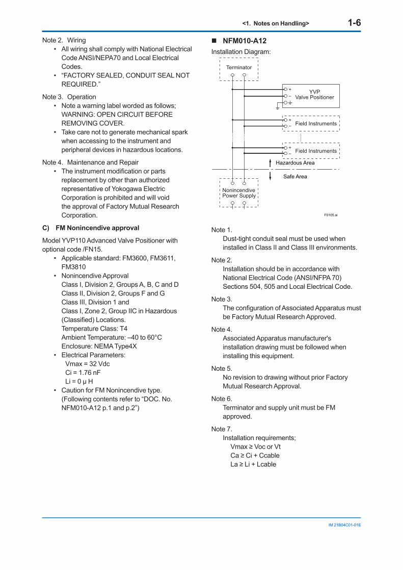
NFM010-A12Installation Diagram:
Safe Area
Hazardous Area
F0105.ai
Terminator
NonincendivePower Supply
Field Instruments
YVPValve Positioner
Field Instruments
+−
+−
+−
Note 1.Dust-tight conduit seal must be used when installed in Class II and Class III environments.
Note 2.Installation should be in accordance with National Electrical Code (ANSI/NFPA 70) Sections 504, 505 and Local Electrical Code.
Note 3.The configuration of Associated Apparatus must be Factory Mutual Research Approved.
Note 4.Associated Apparatus manufacturer's installation drawing must be followed when installing this equipment.
Note 5.No revision to drawing without prior Factory Mutual Research Approval.
Note 6.Terminator and supply unit must be FM approved.
Note 7.Installation requirements; Vmax ≥ Voc or Vt Ca ≥ Ci + Ccable La ≥ Li + Lcable
<1. Notes on Handling> 1-7
IM 21B04C01-01E
1.9.2 ATEX Certification
WARNING
• Do not open the cover when energized.• When the ambient temp.≥70°C,
Use the heat-resisting cable≥90°C• Take care not to generate mechanical
sparking when access to the instrument and peripheral devices in hazardous locations.
• Electrostatic charge may cause an explosion hazard.
Avoid any actions that cause the generation of electrostatic charge, such as rubbing with a dry cloth on coating face of product.
(1) Technical Data
A) ATEX Intrinsically Safe Type (Ex ia)
Caution for ATEX Intrinsically Safe Type.
NOTEKeep the safety use conditions for both 1G and 1D when used in the hazardous gas and dust area.
Note1. Model YVP110 Advanced Valve Positioner with optional code /KS25 for potentially explosive atmospheres:
• Applicable standard: EN60079-0:2006, EN60079-11:2007, EN60079-26:2007, EN60079-27:2006, EN61241-0:2006, EN61241-1:2004, EN61241-11:2006 and EN60529
• Certificate: KEMA 08ATEX0114 X
Note 2. RatingsType of Protection: II 1G Ex ia IIB/IIC T4 II 1D Ex iaD 20 IP65 T100°CII 1D Ex tD A20 IP65 T100°CMaximum Surface Temperature for dust proof.: T100°CAmbient Temperature Ex ia or Ex iaD: –40°C to +60°CAmbient Temperature Ex tD: –40°C to +80°CAmbient Humidity: 0 to 100%RH
(No condensation)
Degree of Protection of the Enclosure: IP65Electrical Parameters:
For Ex ia IIC or Ex iaDUi = 24.0 V, Ii = 250 mA, Pi = 1.2 W,Cint = 1.76 nF, Lint = 0 μH
orFor Ex ia IIB/ IIC or Ex iaD (FISCO model)Ui = 17.5 V, Ii = 380 mA, Pi = 5.32 W,Cint = 1.76 nF, Lint = 0 μH
For II 1D Ex tDInput signal: 32 Vdc, Output current: 17 mA
Note 3. InstallationAll wiring shall comply with local installation requirements. (Refer to the installation diagram)
Note 4. Maintenance and RepairThe instrument modification or parts replacement by other than authorized representative of Yokogawa Electric Corporation is prohibited and will void KEMA Intrinsically safe Certification.
Note 5. Special Conditions for Safe UseBecause the enclosure of the Valve Positioner is made of aluminium, if it is mounted in an area where the use of category 1G apparatus is required, it must be installed such, that, even in the event of rare incidents, ignition sources due to impact and friction sparks are excluded.Once used as apparatus of equipment category 1D in type of protection Ex tD, the valve positioner is no longer suitable as apparatus of equipment category 1G or 1D in type of protection Ex ia or Ex iaD.
Note 6. Installation Instructions When used in a potentially explosive
atmosphere, requiring the use of apparatus of equipment category 1D, suitable certified cable entry devices or certified blanking elements with a degree of ingress protection of at least IP6X according to EN 60529 shall be used and correctly installed.
Note 7. Installation When used in potentially explosive atmosphere
for category 1D, need not use safety barrier.
<1. Notes on Handling> 1-8
IM 21B04C01-01E
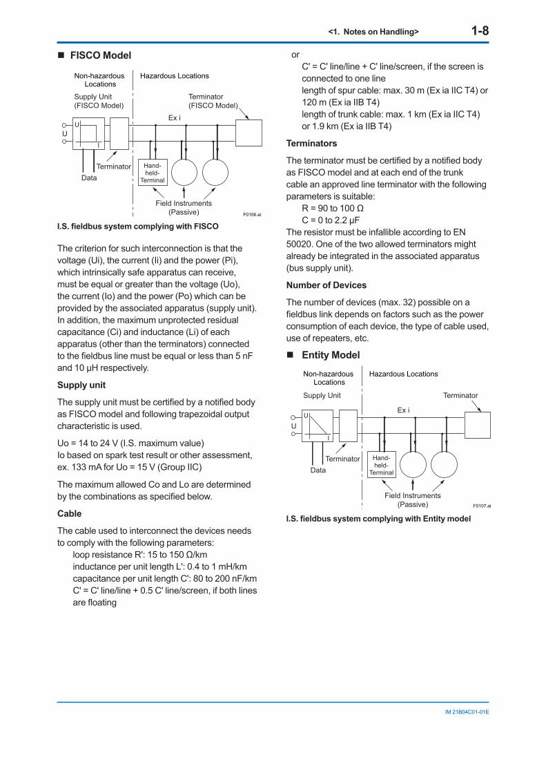
FISCO Model
Non-hazardous Locations
Hazardous Locations
F0106.ai
Terminator(FISCO Model)
Ex i
Field Instruments(Passive)
Hand-held-
Terminal
Supply Unit(FISCO Model)
TerminatorData
UU
I
I.S. fieldbus system complying with FISCO
The criterion for such interconnection is that the voltage (Ui), the current (Ii) and the power (Pi), which intrinsically safe apparatus can receive, must be equal or greater than the voltage (Uo), the current (Io) and the power (Po) which can be provided by the associated apparatus (supply unit). In addition, the maximum unprotected residual capacitance (Ci) and inductance (Li) of each apparatus (other than the terminators) connected to the fieldbus line must be equal or less than 5 nF and 10 µH respectively.
Supply unit
The supply unit must be certified by a notified body as FISCO model and following trapezoidal output characteristic is used.
Uo = 14 to 24 V (I.S. maximum value)Io based on spark test result or other assessment, ex. 133 mA for Uo = 15 V (Group IIC)
The maximum allowed Co and Lo are determined by the combinations as specified below.
Cable
The cable used to interconnect the devices needs to comply with the following parameters:
loop resistance R': 15 to 150 Ω/kminductance per unit length L': 0.4 to 1 mH/kmcapacitance per unit length C': 80 to 200 nF/kmC' = C' line/line + 0.5 C' line/screen, if both lines are floating
orC' = C' line/line + C' line/screen, if the screen is connected to one line length of spur cable: max. 30 m (Ex ia IIC T4) or 120 m (Ex ia IIB T4)length of trunk cable: max. 1 km (Ex ia IIC T4) or 1.9 km (Ex ia IIB T4)
Terminators
The terminator must be certified by a notified body as FISCO model and at each end of the trunk cable an approved line terminator with the following parameters is suitable:
R = 90 to 100 Ω C = 0 to 2.2 µF
The resistor must be infallible according to EN 50020. One of the two allowed terminators might already be integrated in the associated apparatus (bus supply unit).
Number of Devices
The number of devices (max. 32) possible on a fieldbus link depends on factors such as the power consumption of each device, the type of cable used, use of repeaters, etc.
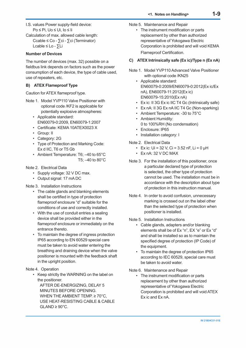
Entity Model
Non-hazardous Locations
Hazardous Locations
F0107.ai
Terminator
Ex i
Field Instruments(Passive)
Hand-held-
Terminal
Supply Unit
TerminatorData
U
UI
I.S. fieldbus system complying with Entity model
<1. Notes on Handling> 1-9
IM 21B04C01-01E
I.S. values Power supply-field device:Po ≤ Pi, Uo ≤ Ui, Io ≤ Ii
Calculation of max. allowed cable length:Ccable ≤ Co - ∑ci - ∑ci (Terminator)Lcable ≤ Lo - ∑Li
Number of Devices
The number of devices (max. 32) possible on a fieldbus link depends on factors such as the power consumption of each device, the type of cable used, use of repeaters, etc.
B) ATEX Flameproof Type
Caution for ATEX flameproof type.
Note 1. Model YVP110 Valve Positioner with optional code /KF2 is applicable for potentially explosive atmospheres:
• Applicable standard: EN60079-0:2009, EN60079-1:2007
• Certificate: KEMA 10ATEX0023 X• Group: II• Category: 2G• Type of Protection and Marking Code:
Ex d IIC, T6 or T5 Gb• Ambient Temperature: T6; –40 to 65°C T5; –40 to 80°C
Note 2. Electrical Data• Supply voltage: 32 V DC max.• Output signal: 17 mA DC
Note 3. Installation Instructions• The cable glands and blanking elements
shall be certified in type of protection flameproof enclosure “d” suitable for the conditions of use and correctly installed.
• With the use of conduit entries a sealing device shall be provided either in the flameproof enclosure or immediately on the entrance thereto.
• To maintain the degree of ingress protection IP65 according to EN 60529 special care must be taken to avoid water entering the breathing and draining device when the valve positioner is mounted with the feedback shaft in the upright position.
Note 4. Operation• Keep strictly the WARNING on the label on
the positioner.AFTER DE-ENERGIZING, DELAY 5 MINUTES BEFORE OPENING.WHEN THE AMBIENT TEMP. ≥ 70°C,USE HEAT-RESISTING CABLE & CABLE GLAND ≥ 90°C.
Note 5. Maintenance and Repair• The instrument modification or parts
replacement by other than authorized representative of Yokogawa Electric Corporation is prohibited and will void KEMA Flameproof Certification.
C) ATEX Intrinsically safe (Ex ic)/Type n (Ex nA)
Note 1. Model YVP110 Advanced Valve Positioner with optional code /KN25
• Applicable standard: EN60079-0:2009/EN60079-0:2012(Ex ic/Ex nA), EN60079-11:2012(Ex ic) EN60079-15:2010(Ex nA)
• Ex ic: II 3G Ex ic IIC T4 Gc (Intrinsically safe) • Ex nA: II 3G Ex nA IIC T4 Gc (Non-sparking) • Ambient Temperature: -30 to 75°C• Ambient Humidity:
0 to 100%RH (No condensation)• Enclosure: IP65• Installation category: I
Note 2. Electrical Data• Ex ic: Ui = 32 V, Ci = 3.52 nF, Li = 0 μH• Ex nA: 32 V DC MAX
Note 3. For the installation of this positioner, once a particular declared type of protection is selected, the other type of protection cannot be used. The installation must be in accordance with the description about type of protection in this instruction manual.
Note 4. In order to avoid confusion, unnecessary marking is crossed out on the label other than the selected type of protection when positioner is installed.
Note 5. Installation Instructions• Cable glands, adapters and/or blanking
elements shall be of Ex “n”, EX “e” or Ex “d” and shall be installed so as to maintain the specified degree of protection (IP Code) of the equipment.
• To maintain the degree of protection IP65 according to IEC 60529, special care must be taken to avoid water.
Note 6. Maintenance and Repair • The instrument modification or parts
replacement by other than authorized representative of Yokogawa Electric Corporation is prohibited and will void ATEX Ex ic and Ex nA.
<1. Notes on Handling> 1-10
IM 21B04C01-01E
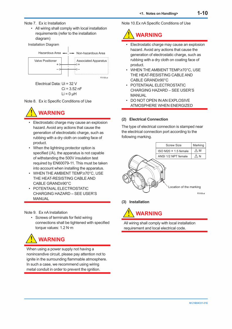
Note 7. Ex ic Installation• All wiring shall comply with local installation
requirements (refer to the installation diagram)
F0108.ai
Valve Positioner
Installation Diagram
Hazardous Area Non-hazardous Area
Associated Apparatus+−
+−
Electrical Data: Ui = 32 V Ci = 3.52 nF Li = 0 μH
Note 8. Ex ic Specific Conditions of Use
WARNING
• Electrostatic charge may cause an explosion hazard. Avoid any actions that cause the generation of electrostatic charge, such as rubbing with a dry cloth on coating face of product.
• When the lightning protector option is specified (/A), the apparatus is not capable of withstanding the 500V insulation test required by EN60079-11. This must be taken into account when installing the apparatus.
• WHEN THE AMBIENT TEMP.≥70°C, USE THE HEAT-RESISTING CABLE AND CABLE GRAND≥90°C
• POTENTAIAL ELECTROSTATIC CHARGING HAZARD – SEE USER’S MANUAL
Note 9. Ex nA Installation• Screws of terminals for field wiring
connections shall be tightened with specified torque values: 1.2 N·m
WARNING
When using a power supply not having a nonincendive circuit, please pay attention not to ignite in the surrounding flammable atmosphere. In such a case, we recommend using wiring metal conduit in order to prevent the ignition.
Note 10. Ex nA Specific Conditions of Use
WARNING
• Electrostatic charge may cause an explosion hazard. Avoid any actions that cause the generation of electrostatic charge, such as rubbing with a dry cloth on coating face of product.
• WHEN THE AMBIENT TEMP.≥70°C, USE THE HEAT-RESISTING CABLE AND CABLE GRAND≥90°C
• POTENTAIAL ELECTROSTATIC CHARGING HAZARD – SEE USER’S MANUAL
• DO NOT OPEN IN AN EXPLOSIVE ATMOSPHERE WHEN ENERGIZED
(2) Electrical Connection
The type of electrical connection is stamped near the electrical connection port according to the following marking.
Location of the marking
Screw Size Marking
ISO M20 × 1.5 female
ANSI 1/2 NPT female
M
N
F0109.ai
(3) Installation
WARNING
All wiring shall comply with local installation requirement and local electrical code.
<1. Notes on Handling> 1-11
IM 21B04C01-01E
The grounding terminals are located on the inside and outside of the terminal area.Connect the cable to grounding terminal in accordance with wiring procedure 1) or 2).
1) Internal grounding terminal
2) External grounding terminal
F0111.ai
Wiring Procedure for Grounding Terminals
(4) Operation
WARNING
• OPEN CIRCUIT BEFORE REMOVING COVER. INSTALL IN ACCORDANCE WITH THIS USER’S MANUAL
• Take care not to generate mechanical sparking when access to the instrument and peripheral devices in hazardous locations.
• Electrostatic charge may cause an explosion hazard. Avoid any actions that cause the generation of electrostatic charge, such as rubbing with a dry cloth on coating face of product.
• Carbon disulphide is excluded for enclosures under gas atmosphere.
(5) Maintenance and Repair
WARNING
The instrument modification or parts replacement by other than authorized Representative of Yokogawa Electric Corporation is prohibited and will void the certification.
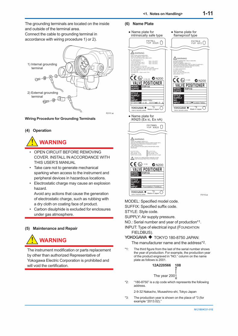
(6) Name Plate
No. KEMA 08ATEX0114 XII 1G Ex ia IIB/IIC T4II 1D Ex iaD 20 IP65 T100°CII 1D Ex tD A20 IP65 T100°CENCLOSURE:IP65For II 1G Ex ia IIC or II 1D Ex iaDUi=24V Ii=250mA Pi=1.2W Ci=1.76nF Li=0µHFor II 1G Ex ia IIC/IIB or II 1D Ex iaD (FISCO field device)Ui=17.5V Ii=380mA Pi=5.32W Ci=1.76nF Li=0µHFor II 1D Ex tDInput signal:32V Output current:17mA
Tamb: −40 to 60°CTamb: −40 to 60°CTamb: −40 to 80°C
0344
II 1G,1D N200
Name plate for intrinsically safe type
Name plate for flameproof type
WARNINGAFTER DE-ENERGIZING, DELAY 5 MINUTESBEFORE OPENING.WHEN THE AMBIENT TEMP.≥70°C,USE THE HEAT-RESISTING CABLE & CABLE GLAND ≥90°C.POTENTIAL ELECTROSTATIC CHARGING HAZARD.SEE USER’S MANUAL BEFORE USE.
No. KEMA 10ATEX0023XEx d IIC T6,T5 GbSUPPLY 32V DC MAXTamb −40 TO 65°C(T6),80°C(T5)ENCLOSURE : IP 65
0344
II 2G N200
9 - 32 V DC Foundation FieldbusFoundation Fieldbus
F0110.ai
TOKYO 180-8750 JAPAN TOKYO 180-8750 JAPAN
WARNINGDON'T OPEN WHEN ENERGIZED.WHEN THE AMBIENT TEMP. ≥70°CUSE THE HEAT-RESISTING CABLE ≥90°C
F9176LLYVP KS25
9-17.5(24)V DC (Ex ia, iaD) 9-32.0V DC (Ex tD)
Made in Japan Made in Japan
F9176LKYVP KF2
Name plate for /KN25 (Ex ic, Ex nA)
WARNINGWHEN THE AMBIENT TEMP.≥70°C,USE THE HEAT-RESISTING CABLE & CABLE GLAND ≥90°C.POTENTIAL ELECTROSTATIC CHARGING HAZARD.- SEE USER’S MANUALDO NOT OPEN IN AN EXPLOSIVE ATMOSPHERE WHENENERGIZED
CROSS OUT UNNECESSARY MARKING OTHERTHAN THE SELECTED TYPE OF PRPTECTION
II 3G N200
TOKYO 180-8750 JAPANMade in Japan
F9176MQYVP KN25
Foundation Fieldbus
Ex ic IIC T4 GcTamb −30 TO 75°CENCLOSURE : IP 65Ui=32V, Ci=3.52nF, Li=0µH
Ex nA IIC T4 GcTamb −30 TO 75°CENCLOSURE : IP 65SUPPLY 32V DC MAX
*3
*3
*3
MODEL: Specified model code.SUFFIX: Specified suffix code.STYLE: Style code.SUPPLY: Air supply pressure.NO.: Serial number and year of production*1.INPUT: Type of electrical input (FOUNDATION
FIELDBUS). TOKYO 180-8750 JAPAN:
The manufacturer name and the address*2.*1: The third figure from the last of the serial number shows
the year of production. For example, the production year of the product engraved in “NO.” column on the name plate as follows is 2001.
The year 2001
12A220566 108
*2: “180-8750” is a zip code which represents the following address.
2-9-32 Nakacho, Musashino-shi, Tokyo Japan
*3: The production year is shown on the place of *3 (for example “2013.02).”
<1. Notes on Handling> 1-12
IM 21B04C01-01E
1.9.3 CSA Certification
A) CSA Explosionproof Type
Cautions for CSA Explosionproof type.
Note 1. Model YVP110 Advanced Valve Positioner with optional code /CF1 are applicable for use in hazardous locations:
• Applicable standard: C22.2 No. 0, No. 0.4, No. 0.5, No. 25, No. 30, No. 94, No. 1010.1
• Certificate: 1186507• Explosionproof for Class I, Groups B, C and
D; Class II, Groups E, F and G; Class III.• Enclosure Rating: Type 4X• Temperature Code: T6 and T5• Ambient Temperature: –40 to 75°C for T6,
–40 to 82°C for T5
Note 2. Wiring• All wiring shall comply with National Electrical
Code ANSI/NFPA 70 and Local Electrical Codes.
• “FACTORY SEALED, CONDUIT SEAL NOT REQUIRED.”
• When the ambient temperature is 60°C or more, use an external cable having a maximum allowable heat-resistance of at least 90°C.
Note 3. Maintenance and Repair• The instrument modification or parts
replacement by other than authorized representative of Yokogawa Electric Corporation is prohibited and will void CSA Certification.
1.9.4 TIIS Certification
A) TIIS Flameproof Type
The model YVP110 Valve Positioner with optional code /JF3, which has obtained certification according to technical criteria for explosion-protected construction of electric machinery and equipment (Standards Notification No. 556 from the Japanese Ministry of Labor) conforming to IEC standards, is designed for hazardous areas where inflammable gases or vapors may be present. (This allows installation in Division 1 and 2 areas)
To preserve the safety of flameproof equipment requires great care during mounting, wiring, and piping. Safety requirements also place restrictions on maintenance and repair activities. Users absolutely must read “Installation and Operating Precautions for JIS Flameproof Equipment” at the end of this manual.
CAUTIONWhen selecting cables for TIIS flameproof type positioners, use cables having a maximum allowable heat resistance of at least 70°C.
<2. Part Names> 2-1
IM 21B04C01-01E
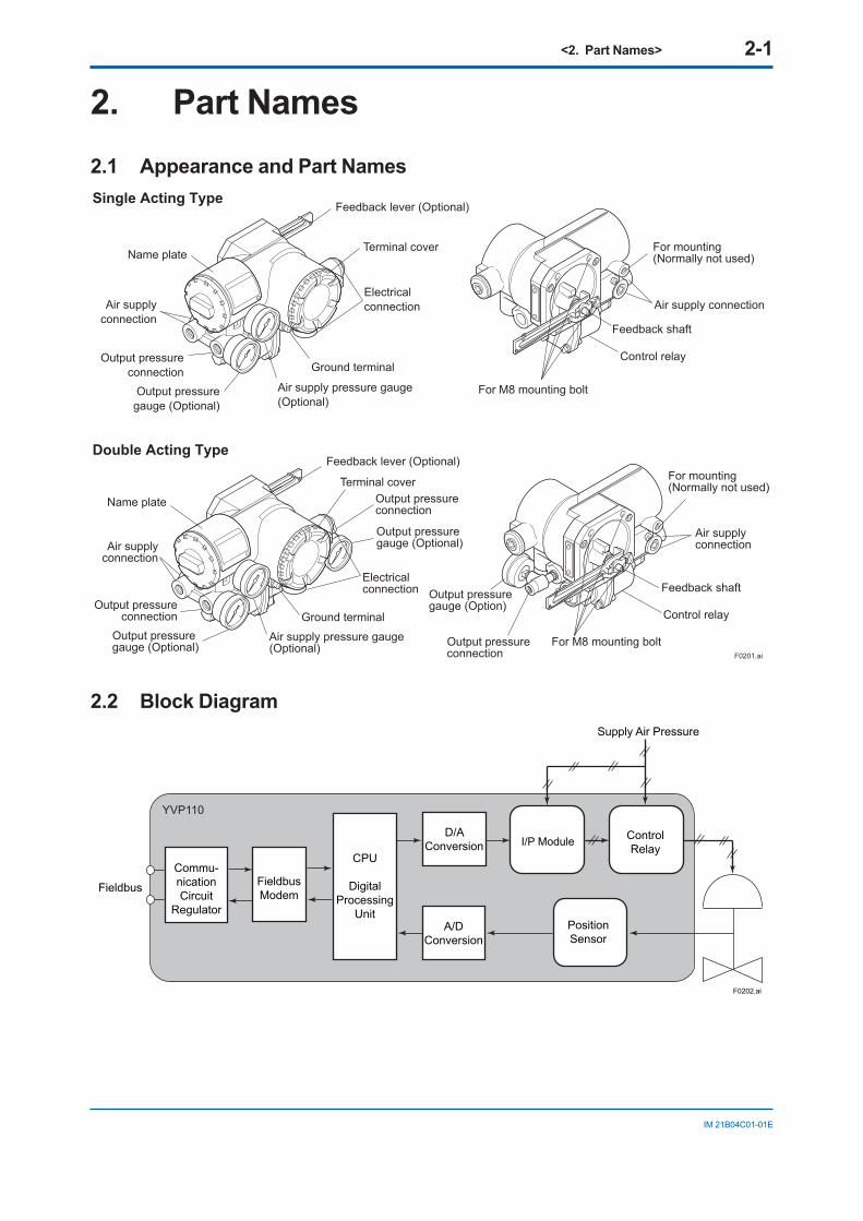
2. Part Names2.1 Appearance and Part Names
Feedback lever (Optional)
Terminal coverName plate
Air supplyconnection
Output pressureconnection
Air supply pressure gauge(Optional)
Output pressuregauge (Optional)
Ground terminal
Electricalconnection
Control relay
Air supply connection
Feedback shaft
For mounting(Normally not used)
For M8 mounting bolt
Feedback lever (Optional)
Terminal coverOutput pressure connection
Output pressuregauge (Optional)
Name plate
Electrical connection
Air supplyconnection
Output pressureconnection
Air supply pressure gauge(Optional)
Output pressure gauge (Optional)
Ground terminal
F0201.ai
Control relay
Air supply connection
Feedback shaft
For M8 mounting bolt
Output pressuregauge (Option)
Output pressureconnection
For mounting(Normally not used)
Single Acting Type
Double Acting Type
2.2 Block DiagramSupply Air Pressure
Fieldbus
F0202.ai
Commu-nicationCircuit
Regulator
CPU
DigitalProcessing
Unit
D/AConversion
A/DConversion
I/P Module ControlRelay
PositionSensor
FieldbusModem
YVP110
<3. Installing YVP110 on Actuator> 3-1
IM 21B04C01-01E
3. Installing YVP110 on Actuator3.1 GeneralFor installation of a YVP110, see Section 1.4, “Choosing the Installation Location.” For the ambient, environmental conditions required for installation, see Chapter 7, “General Specifications.”
WARNING
To avoid injury or the process being affected when installing or replacing a positioner on a control valve, ensure that:
• All inputs to the valve actuator and other accessories of the valve and actuator, including the air supply and electric signal, are cut off.
• The process has been shut down or the control valve is isolated from the process by using bypass valves or the like.
• No pressure remains in the valve actuator.
3.2 Installing YVP110 on Actuator
A YVP110 can be installed on a valve actuator with a mounting bracket. Prepare the bracket and clamp which are necessary to install the valve, according to the valve. In general, the installation method is determined by the combination of the control valve and positioner as well as by the valve manufacturer who performs the adjustment. For details, consult the control valve manufacturer.
Required Tools: To install a YVP110, you need to prepare:
• Nominal 13-mm open end or box end wrench for M8 bolts used to fix the mounting bracket to the positioner.
• Nominal 10-mm open end or box end wrench for M6 bolt used to fix the feedback lever to the shaft.
3.2.1 Installing YVP110 on Linear-motion Control Valve
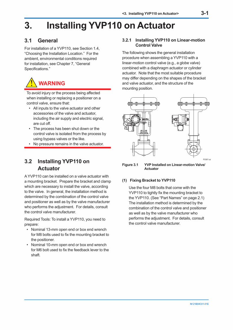
The following shows the general installation procedure when assembling a YVP110 with a linear-motion control valve (e.g., a globe valve) combined with a diaphragm actuator or cylinder actuator. Note that the most suitable procedure may differ depending on the shapes of the bracket and valve actuator, and the structure of the mounting position.
F0301.ai
Figure 3.1 YVP Installed on Linear-motion Valve/Actuator
(1) Fixing Bracket to YVP110
Use the four M8 bolts that come with the YVP110 to tightly fix the mounting bracket to the YVP110. (See “Part Names” on page 2.1) The installation method is determined by the combination of the control valve and positioner as well as by the valve manufacturer who performs the adjustment. For details, consult the control valve manufacturer.
<3. Installing YVP110 on Actuator> 3-2
IM 21B04C01-01E
(2) Fixing the YVP110 to Actuator with Bracket
After fixing the bracket to the YVP110, attach it to the actuator with the specified bolts. Depending on the shapes of the bracket and actuator, the working space at the rear of the YVP110 where the feedback shaft is positioned may be quite narrow, making installation work tricky. In such a case, the entire procedure may be made much easier by attaching the feedback lever to the feedback shaft as described in step (3), prior to carrying out step (2). Check the space behind the YVP110 beforehand.
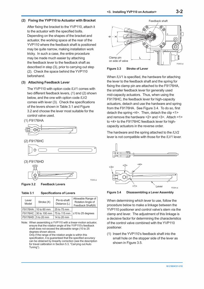
(3) Attaching Feedback Lever
The YVP110 with option code /LV1 comes with two different feedback levers, (1) and (2) shown below, and the one with option code /LV2 comes with lever (3). Check the specifications of the levers shown in Table 3.1 and Figure 3.2 and choose the lever most suitable for the control valve used.
F0302.ai
(1) F9176HA
(2) F9176HC
(3) F9176HD
Figure 3.2 Feedback Levers
Table 3.1 Specifications of Levers
Lever Model Stroke (X) Pin-to-shaft
Distance (L)
Allowable Range of Rotation Angle of
Feedback Shaft(θ)F9176HA 10 to 60 mm 25 to 75 mm
±10 to 25 degreesF9176HC 30 to 100 mm 75 to 115 mmF9176HD 5 to 20 mm 14 to 20 mm
Note: When assembling a YVP110 with a linear-motion actuator, ensure that the rotation angle of the YVP110’s feedback shaft does not exceed the allowable range (10 to 25 degrees shown above.
Only if the range of the rotation angle is within this specification, it is guaranteed that the specified accuracy can be obtained by linearity correction (see the description for travel calibration in Section 5.3, “Carrying out Auto Tuning”).
F0303.ai
L
Xθ
Feedback shaft
Clamp pin on side of valve
SUP
Figure 3.3 Stroke of Lever
When /LV1 is specified, the hardware for attaching the lever to the feedback shaft and the spring for fixing the clamp pin are attached to the F9176HA, the smaller feedback lever for generally used mid-capacity actuators. Thus, when using the F9176HC, the feedback lever for high-capacity actuators, detach and use the hardware and spring from the F9176HA. See Figure 3.4. To do so, first detach the spring <4>. Then, detach the clip <1> and remove the hardware <2> and <3>. Attach <1> to <4> to the F9176HC feedback lever for high-capacity actuators in the reverse order.
The hardware and the spring attached to the /LV2 lever is not compatible with those for the /LV1 lever.
F0304.ai
<3> <2> <4>
<1> Lever
Figure 3.4 Disassembling a Lever Assembly
When determining which lever to use, follow the procedure below to make a linkage between the YVP110 positioner and control valve’s stem via the clamp and lever. The adjustment of this linkage is a decisive factor for determining the characteristics of the control valve combined with the YVP110 positioner.
(1) Insert the YVP110’s feedback shaft into the small hole on the stopper side of the lever as shown in Figure 3.5.
<3. Installing YVP110 on Actuator> 3-3
IM 21B04C01-01E
CAUTIONIt is extremely likely that attaching the lever in the wrong orientation will cause the feedback shaft to rotate at an angle exceeding its mechanical limits of ±55 degrees, resulting in the YVP110 being seriously damaged.
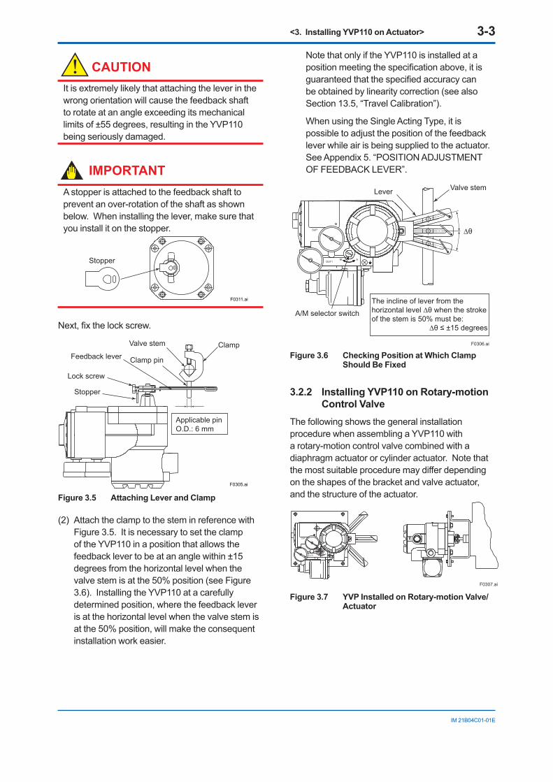
IMPORTANTA stopper is attached to the feedback shaft to prevent an over-rotation of the shaft as shown below. When installing the lever, make sure that you install it on the stopper.
F0311.ai
Stopper
Next, fix the lock screw.
Feedback lever
Valve stem
Clamp pin
Lock screw
Applicable pin O.D.: 6 mm
Stopper
Clamp
F0305.ai
Figure 3.5 Attaching Lever and Clamp
(2) Attach the clamp to the stem in reference with Figure 3.5. It is necessary to set the clamp of the YVP110 in a position that allows the feedback lever to be at an angle within ±15 degrees from the horizontal level when the valve stem is at the 50% position (see Figure 3.6). Installing the YVP110 at a carefully determined position, where the feedback lever is at the horizontal level when the valve stem is at the 50% position, will make the consequent installation work easier.
Note that only if the YVP110 is installed at a position meeting the specification above, it is guaranteed that the specified accuracy can be obtained by linearity correction (see also Section 13.5, “Travel Calibration”).
When using the Single Acting Type, it is possible to adjust the position of the feedback lever while air is being supplied to the actuator. See Appendix 5. “POSITION ADJUSTMENT OF FEEDBACK LEVER”.
F0306.ai
The incline of lever from the horizontal level ∆θ when the stroke of the stem is 50% must be:
∆θ ≤ ±15 degrees
A/M selector switch
Valve stemLever
∆θ
Figure 3.6 Checking Position at Which Clamp Should Be Fixed
3.2.2 Installing YVP110 on Rotary-motion Control Valve
The following shows the general installation procedure when assembling a YVP110 with a rotary-motion control valve combined with a diaphragm actuator or cylinder actuator. Note that the most suitable procedure may differ depending on the shapes of the bracket and valve actuator, and the structure of the actuator.
F0307.ai
Figure 3.7 YVP Installed on Rotary-motion Valve/Actuator
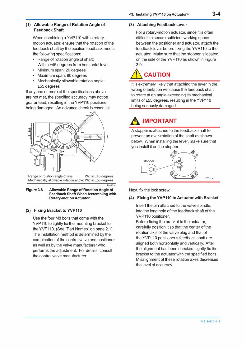
<3. Installing YVP110 on Actuator> 3-4
IM 21B04C01-01E
(1) Allowable Range of Rotation Angle of Feedback Shaft
When combining a YVP110 with a rotary-motion actuator, ensure that the rotation of the feedback shaft by the position feedback meets the following specifications: • Range of rotation angle of shaft:
Within ±45 degrees from horizontal level• Minimum span: 20 degrees• Maximum span: 90 degrees• Mechanically allowable rotation angle:
±55 degrees If any one or more of the specifications above are not met, the specified accuracy may not be guaranteed, resulting in the YVP110 positioner being damaged. An advance check is essential.
θ
Range of rotation angle of shaft: Within ±45 degreesMechanically allowable rotation angle: Within ±55 degrees
F0308.ai
Figure 3.8 Allowable Range of Rotation Angle of Feedback Shaft When Assembling with Rotary-motion Actuator
(2) Fixing Bracket to YVP110
Use the four M8 bolts that come with the YVP110 to tightly fix the mounting bracket to the YVP110. (See “Part Names” on page 2.1) The installation method is determined by the combination of the control valve and positioner as well as by the valve manufacturer who performs the adjustment. For details, consult the control valve manufacturer.
(3) Attaching Feedback Lever
For a rotary-motion actuator, since it is often difficult to secure sufficient working space between the positioner and actuator, attach the feedback lever before fixing the YVP110 to the actuator. Make sure that the stopper is located on the side of the YVP110 as shown in Figure 3.9.
CAUTIONIt is extremely likely that attaching the lever in the wrong orientation will cause the feedback shaft to rotate at an angle exceeding its mechanical limits of ±55 degrees, resulting in the YVP110 being seriously damaged.
IMPORTANTA stopper is attached to the feedback shaft to prevent an over-rotation of the shaft as shown below. When installing the lever, make sure that you install it on the stopper.
F0311.ai
Stopper
Next, fix the lock screw.
(4) Fixing the YVP110 to Actuator with Bracket
Insert the pin attached to the valve spindle, into the long hole of the feedback shaft of the YVP110 positioner. Before fixing the bracket to the actuator, carefully position it so that the center of the rotation axis of the valve plug and that of the YVP110 poistioner’s feedback shaft are aligned both horizontally and vertically. After the alignment has been checked, tightly fix the bracket to the actuator with the specified bolts. Misalignment of these rotation axes decreases the level of accuracy.
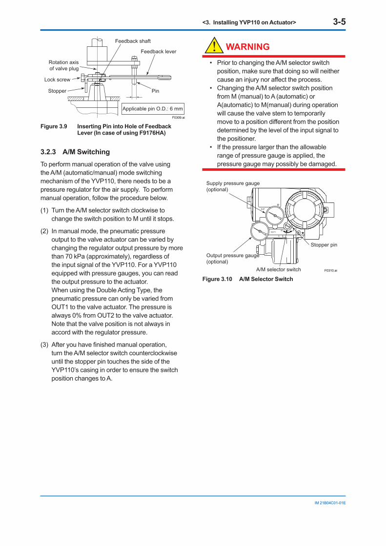
<3. Installing YVP110 on Actuator> 3-5
IM 21B04C01-01E
Feedback shaft
Feedback lever
Rotation axisof valve plug
Pin
Applicable pin O.D.: 6 mmF0309.ai
Lock screw
Stopper
Figure 3.9 Inserting Pin into Hole of Feedback Lever (In case of using F9176HA)
3.2.3 A/M SwitchingTo perform manual operation of the valve using the A/M (automatic/manual) mode switching mechanism of the YVP110, there needs to be a pressure regulator for the air supply. To perform manual operation, follow the procedure below.
(1) Turn the A/M selector switch clockwise to change the switch position to M until it stops.
(2) In manual mode, the pneumatic pressure output to the valve actuator can be varied by changing the regulator output pressure by more than 70 kPa (approximately), regardless of the input signal of the YVP110. For a YVP110 equipped with pressure gauges, you can read the output pressure to the actuator. When using the Double Acting Type, the pneumatic pressure can only be varied from OUT1 to the valve actuator. The pressure is always 0% from OUT2 to the valve actuator. Note that the valve position is not always in accord with the regulator pressure.
(3) After you have finished manual operation, turn the A/M selector switch counterclockwise until the stopper pin touches the side of the YVP110’s casing in order to ensure the switch position changes to A.
WARNING
• Prior to changing the A/M selector switch position, make sure that doing so will neither cause an injury nor affect the process.
• Changing the A/M selector switch position from M (manual) to A (automatic) or A(automatic) to M(manual) during operation will cause the valve stem to temporarily move to a position different from the position determined by the level of the input signal to the positioner.
• If the pressure larger than the allowable range of pressure gauge is applied, the pressure gauge may possibly be damaged.
A/M selector switch
Stopper pin
Supply pressure gauge (optional)
Output pressure gauge (optional)
F0310.ai
Figure 3.10 A/M Selector Switch
<4. Wiring and Piping> 4-1
IM 21B04C01-01E
4. Wiring and Piping4.1 GeneralThis chapter describes the air piping and electric wiring connections.
WARNING
• Be sure to cut off all inputs to the valve actuator and other accessories of the valve and actuator, including the air supply and electric signal before making or modifying the piping and wiring connections.
• The process must be shut down or the control valve isolated from the process by using bypass valves or the like when making or modifying the piping and wiring connections.
• Always cap the unused wiring ports with blind plugs.
4.2 Piping4.2.1 Air SupplyFor stable operation of the YVP110 over a long term, a clean and dry supply of air needs to be maintained. Therefore, be careful about the following:
(1) To prevent moisture, oil, and dust from being led into the YVP110 through pipes, give careful consideration to the choice of the air supply system and supply air suction point as well as installation of the air supply header and air supply piping.
(2) The desired supply air must: • Be dry air whose dew point is at least 10°C
lower than that of the ambient temperature. • Be free from solid particles as a result of
being passed through a 5-µm or finer filter. • Not contain oil at a concentration higher than
1 ppm in weight or volume. • Not be contaminated by a corrosive,
explosive, flammable, or toxic gas. • Comply with ANSI/ISA-57.3 1975 (R1981) or
ISA-S7.3-1975 (R1981).
(3) The YVP110 requires an air supply of 140 to 400 kPa. Within this range, regulate the air supply pressure at a level within ±10% of the air supply pressure specified for the actuator, and at 10% of the actuator’s spring range or higher.
WARNING
Do not supply air at a pressure exceeding the maximum rated air supply pressure of the actuator or the YVP110 (400 kPa). Doing so may result in a high risk of damage to the equipment or lead to an accident. Supplying air to the valve actuator may cause the valve stem to move. Exercise extreme caution with regard to safety.
4.2.2 Pneumatic PipingConnect the air supply pipe to the SUP port of the YVP110, and the output pressure pipe to the OUT1 port. When using the Double Acting Type, connect the output pressure pipe to the OUT2 port of the YVP110. A power failure will result in the fail-safe action; OUT1=0% and OUT2=100%. Use O.D. 6-mm/I.D. 4-mm or O.D. 8-mm/I.D. 6-mm copper tubes for piping, and pneumatic pipe fittings for joints. After finishing the piping, check that there is no leakage from the joints.
Note that a YVP110 has two air supply ports (SUP): one at the rear and the other on the side. When delivered, the rear SUP port is capped with a blind plug. Thus, to use the rear SUP port, remove the blind plug and cap the side SUP port with it. At this time, be very careful that no foreign matter or dust caught in the sealing tape is allowed to enter inside the pipe.
Figure 4.1 shows the pneumatic piping ports. The port specification can be chosen when ordering the YVP110.
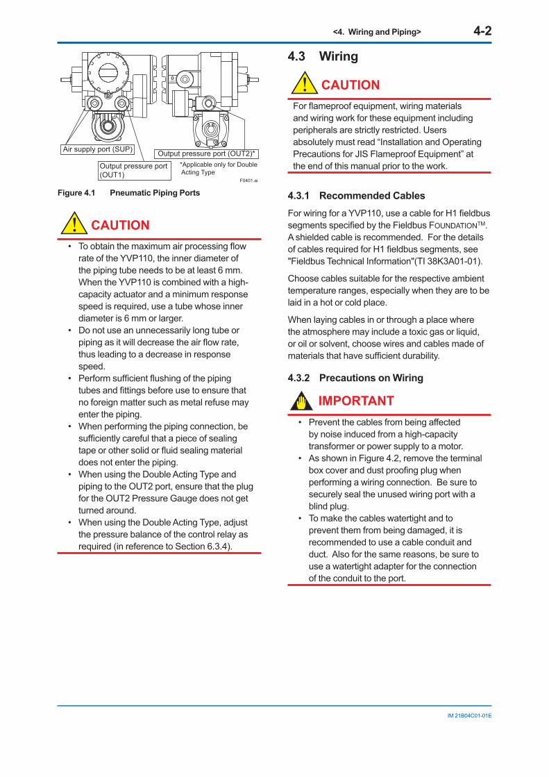
<4. Wiring and Piping> 4-2
IM 21B04C01-01E
F0401.ai
Air supply port (SUP)
Output pressure port (OUT1)
Output pressure port (OUT2)**Applicable only for Double Acting Type
OUT2
Figure 4.1 Pneumatic Piping Ports
CAUTION• To obtain the maximum air processing flow
rate of the YVP110, the inner diameter of the piping tube needs to be at least 6 mm. When the YVP110 is combined with a high-capacity actuator and a minimum response speed is required, use a tube whose inner diameter is 6 mm or larger.
• Do not use an unnecessarily long tube or piping as it will decrease the air flow rate, thus leading to a decrease in response speed.
• Perform sufficient flushing of the piping tubes and fittings before use to ensure that no foreign matter such as metal refuse may enter the piping.
• When performing the piping connection, be sufficiently careful that a piece of sealing tape or other solid or fluid sealing material does not enter the piping.
• When using the Double Acting Type and piping to the OUT2 port, ensure that the plug for the OUT2 Pressure Gauge does not get turned around.
• When using the Double Acting Type, adjust the pressure balance of the control relay as required (in reference to Section 6.3.4).
4.3 Wiring
CAUTIONFor flameproof equipment, wiring materials and wiring work for these equipment including peripherals are strictly restricted. Users absolutely must read “Installation and Operating Precautions for JIS Flameproof Equipment” at the end of this manual prior to the work.
4.3.1 Recommended CablesFor wiring for a YVP110, use a cable for H1 fieldbus segments specified by the Fieldbus FOUNDATIONTM. A shielded cable is recommended. For the details of cables required for H1 fieldbus segments, see "Fieldbus Technical Information"(TI 38K3A01-01).
Choose cables suitable for the respective ambient temperature ranges, especially when they are to be laid in a hot or cold place.
When laying cables in or through a place where the atmosphere may include a toxic gas or liquid, or oil or solvent, choose wires and cables made of materials that have sufficient durability.
4.3.2 Precautions on Wiring
IMPORTANT• Prevent the cables from being affected
by noise induced from a high-capacity transformer or power supply to a motor.
• As shown in Figure 4.2, remove the terminal box cover and dust proofing plug when performing a wiring connection. Be sure to securely seal the unused wiring port with a blind plug.
• To make the cables watertight and to prevent them from being damaged, it is recommended to use a cable conduit and duct. Also for the same reasons, be sure to use a watertight adapter for the connection of the conduit to the port.
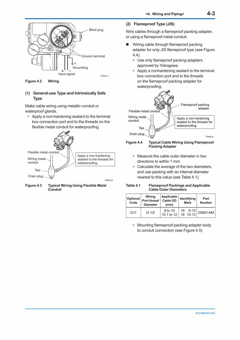
<4. Wiring and Piping> 4-3
IM 21B04C01-01E
F0402.ai
Blind plug
Grounding
Input signal
Ground terminal
–
Figure 4.2 Wiring
(1) General-use Type and Intrinsically Safe Type
Make cable wiring using metallic conduit or waterproof glands.
• Apply a non-hardening sealant to the terminal box connection port and to the threads on the flexible metal conduit for waterproofing.
F0403.ai
Flexible metal conduit
Wiring metalconduit
Tee
Drain plug
Apply a non-hardeningsealant to the threads forwaterproofing.
Figure 4.3 Typical Wiring Using Flexible Metal Conduit
(2) Flameproof Type (JIS)
Wire cables through a flameproof packing adapter, or using a flameproof metal conduit.
Wiring cable through flameproof packing adapter for only JIS flameproof type (see Figure 4.4).• Use only flameproof packing adapters
approved by Yokogawa.• Apply a nonhardening sealant to the terminal
box connection port and to the threads on the flameproof packing adapter for waterproofing.
Flameproof packing adapter
Flexible metal conduit
Wiring metalconduit
Tee
Drain plug
Apply a non-hardeningsealant to the threads forwaterproofing.
F0404.ai
Figure 4.4 Typical Cable Wiring Using Flameproof Packing Adapter
• Measure the cable outer diameter in two directions to within 1 mm.
• Calculate the average of the two diameters, and use packing with an internal diameter nearest to this value (see Table 4.1).
Table 4.1 Flameproof Packings and Applicable Cable Outer Diameters
Optional Code
Wiring Port thread Diameter
Applicable Cable OD
(mm)
Identifying Mark
Part Number
G11 G 1/2 8 to 1010.1 to 12
1616
8-1010-12 G9601AM
• Mounting flameproof packing adapter body to conduit connection (see Figure 4.5)
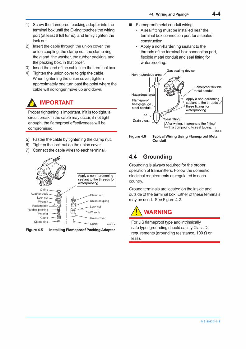
<4. Wiring and Piping> 4-4
IM 21B04C01-01E
1) Screw the flameproof packing adapter into the terminal box until the O-ring touches the wiring port (at least 6 full turns), and firmly tighten the lock nut.
2) Insert the cable through the union cover, the union coupling, the clamp nut, the clamp ring, the gland, the washer, the rubber packing, and the packing box, in that order.
3) Insert the end of the cable into the terminal box.4) Tighten the union cover to grip the cable.
When tightening the union cover, tighten approximately one turn past the point where the cable will no longer move up and down.
IMPORTANTProper tightening is important. If it is too tight, a circuit break in the cable may occur; if not tight enough, the flameproof effectiveness will be compromised.
5) Fasten the cable by tightening the clamp nut.6) Tighten the lock nut on the union cover.7) Connect the cable wires to each terminal.
O-ringAdapter body
Lock nutWrench
Packing boxRubber packing
WasherGland
Clamp ring
Clamp nut
Union coupling
Lock nut
Wrench
Union cover
Cable
Apply a non-hardneningsealant to the threads forwaterproofing.
F0405.ai
Figure 4.5 Installing Flameproof Packing Adapter
Flameproof metal conduit wiring• A seal fitting must be installed near the
terminal box connection port for a sealed construction.
• Apply a non-hardening sealant to the threads of the terminal box connection port, flexible metal conduit and seal fitting for waterproofing.
F0406.ai
Non-hazardous area
Hazardous area
Flameproofheavy-gaugesteel conduit
TeeDrain plug Seal fitting
Gas sealing device
Flameproof flexiblemetal conduit
Apply a non-hardeningsealant to the threads ofthese fittings forwaterproofing
After wiring, impregnate the fittingwith a compound to seal tubing.
Figure 4.6 Typical Wiring Using Flameproof Metal Conduit
4.4 GroundingGrounding is always required for the proper operation of transmitters. Follow the domestic electrical requirements as regulated in each country.
Ground terminals are located on the inside and outside of the terminal box. Either of these terminals may be used. See Figure 4.2.
WARNING
For JIS flameproof type and intrinsically safe type, grounding should satisfy Class D requirements (grounding resistance, 100 Ω or less).
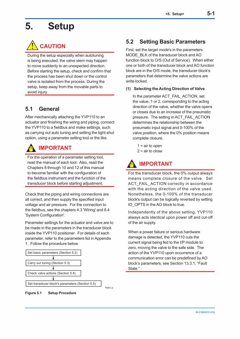
<5. Setup> 5-1
IM 21B04C01-01E
5. Setup
CAUTIONDuring the setup especially when autotuning is being executed, the valve stem may happen to move suddenly to an unexpected direction. Before starting the setup, check and confirm that the process has been shut down or the control valve is isolated from the process. During the setup, keep away from the movable parts to avoid injury.
5.1 GeneralAfter mechanically attaching the YVP110 to an actuator and finishing the wiring and piping, connect the YVP110 to a fieldbus and make settings, such as carrying out auto tuning and setting the tight-shut option, using a parameter setting tool or the like.
IMPORTANTFor the operation of a parameter setting tool, read the manual of each tool. Also, read the Chapters 8 through 10 and 12 of this manual to become familiar with the configuration of the fieldbus instrument and the function of the transducer block before starting adjustment.
Check that the piping and wiring connections are all correct, and then supply the specified input voltage and air pressure. For the connection to the fieldbus, see the chapters 4.3 'Wiring' and 8.4 'System Configuration'.
Parameter settings for the actuator and valve are to be made in the parameters in the transducer block inside the YVP110 positioner. For details of each parameter, refer to the parameters list in Appendix 1. Follow the procedure below.
Set basic parameters (Section 5.2)
Carry out tuning (Section 5.3)
Check valve actions (Section 5.4)
Set transducer block's parameters (Section 5.5)F0501.ai
Figure 5.1 Setup Procedure
5.2 Setting Basic ParametersFirst, set the target mode's in the parameters MODE_BLK of the transducer block and AO function block to O/S (Out of Service). When either one or both of the transducer block and AO function block are in the O/S mode, the transducer block's parameters that determine the valve actions are write-locked.
(1) Selecting the Acting Direction of Valve
In the parameter ACT_FAIL_ACTION, set the value, 1 or 2, corresponding to the acting direction of the valve, whether the valve opens or closes due to an increase of the pneumatic pressure. The setting in ACT_FAIL_ACTION determines the relationship between the pneumatic input signal and 0-100% of the valve position, where the 0% position means complete closure.
1 = air to open 2 = air to close
IMPORTANTFor the transducer block, the 0% output always means complete closure of the valve. Set ACT_FAIL_ACTION correctly in accordance with the acting direction of the valve used. Nonetheless, the 0-100% of the transducer block's output can be logically reversed by setting IO_OPTS in the AO block to true.
Independently of the above setting, YVP110 always acts identical upon power off and cut-off of the air supply.
When a power failure or serious hardware damage is detected, the YVP110 cuts the current signal being fed to the I/P module to zero, moving the valve to the safe side. The action of the YVP110 upon occurrence of a communication error can be predefined by AO block’s parameters; see Section 13.3.1, “Fault State.”
<5. Setup> 5-2
IM 21B04C01-01E
(2) Selecting the Actuator Type
For the parameter VALVE_TYPE, set the value, 1 or 2, in accordance with the actuator type.
1 = linear-motion actuator 2 = rotary-motion actuator
Choosing the linear-motion type automatically corrects a linearity error that is inherently caused between the linearly acting actuator and the rotating displacement sensor inside the YVP110 actuator.
5.3 Carrying out Tuning
CAUTIONThis function strokes the valve over its full range. Do not execute while valve is controlling the process. Keep away from the movable parts to avoid injury.
After selecting the acting direction of the valve and the actuator type, carry out auto tuning (and manual tuning, if necessary). The auto tuning program automatically:
• Adjusts the zero-point and span. • Adjusts the parameter settings for controlling
the valve.
IMPORTANTAuto Tuning in YVP110 sets the 0% point at the position where the valve is fully closed and 100% point at the position where the valve stem stops against the mechanical stopper(fully open). If it is necessary to adjust the zero point and span precisely to the rated stroke of the valve, carry out travel calibration which is described later in this chapter after the Auto Tuning.
To carry out auto tuning, write a value to the parameter AUTO_TUNE_EXEC according to the following procedure.
CAUTIONFor the first time after installing the YVP110 on the actuator or anytime after detaching the YVP110 and installing it again on the actuator, be sure to perform step (1) below, or (2) and (3) to carry out all adjustments. Otherwise, the adjustments cannot be carried out correctly. From the next and any time thereafter, perform only step (2) or (3) independently. After detaching the YVP110 from the valve actuator and then reinstalling it to the actuator, be sure to perform step (2) below.
(1) To sequentially adjust the zero-point and span, and then control parameter settings for the first time after installing the YVP110 on a valve actuator, write: 4 (= travel calibration at stop point and
control parameter tuning).
(2) To leave the control parameter settings unchanged and only perform zero-point and span adjustments such as after detaching the YVP110 from the valve actuator and restoring it, write: 2 (= travel calibration at stop point).
(3) To leave zero-point and span settings unchanged and only adjust control parameter settings, such as after the hysteresis of the valve actions has greatly changed, write: 3 (= control parameter tuning).
The time needed to complete the adjustments, which varies with the actuator size and the hysteresis of the actions, is roughly 4 minutes for a mid-capacity (capacity of around 3 liters) actuator.
If you want to abort auto tuning for some reason such as when you have started it while leaving the air supply shut off, write: 5 (= cancel execution).
<5. Setup> 5-3
IM 21B04C01-01E
The tuning result will be written to AUTO_TUNE_RESULT. The value of AUTO_TUNE_RESULT is 255 and is displayed as “In operation” while auto tuning is running, and will change to 1 which is displayed as “Succeeded” when auto tuning has finished successfully. In the event of a warning or error, a value other than those below will be displayed. For details, see the specifications for the transducer block. 1 = succeeded 2 = canceled 255 = in operation
The values of the hysteresis of valve actions and the air supply pressure measured during auto tuning are stored in parameters of the transducer block inside the YVP110. Note that pressure data such as air supply pressure data are available only for a YVP110 with an optional pressure sensor.
CAUTIONEnsure that the pressure of the air supply to the YVP110 positioner is regulated within the specified range. If it differs from the pressure during actual operation, or if it is unstable, optimum tuning results may not be obtained.
The following parameters are tuned by carrying out auto tuning: (For details, see secction A6.4)
SERVO_GAIN (static loop gain of internal valve control loop)
SERVO_RESET (integral time)SERVO_RATE (derivative time)SERVO_RATE_GAIN (derivative gain)SERVO_DEADBAND
(dead band of integral action)SERVO_OFFSET (offset of integral action)BOOST_ON_THRESHOLD
(threshold to switch on the boost action)BOOST_OFF_THRESHOLD
(threshold to switch off the boost action)BOOST_VALUESERVO_I_SLEEP_LMT
(timer setting for integral action)SERVO_P_ALPHA
(multiplication coefficient for the square of proportional factor)
INTERNAL_GAIN (total gain of I/P module,control relay and the valve)
X_BST_ON_THRESHOLD * (the addition value to threshold for switching on boost action for exhaust.)
X_BST_OFF_THRESHOLD * (the addition value to threshold for switching off boost action for exhaust)
X_BOOST_VALUE * (the addition boost value for exhaust)
*Applicable only for Double Acting Type
Normally, control parameters need not be readjusted after auto tuning. (Should there be a problem, see Chapter 16, “Troubleshooting.”)If you want to carry out fine adjustments of the zero-point and span settings, perform the travel calibration as follows.
l Travel Calibration
If the full stroke of the valve is too large for the maximum required flow rate, you can change the span of the travel by carrying out a travel calibration.
(1) First, vary the value of FINAL_VALUE.value (see caution) to move the stem and adjust the stem to the desired point that you want to set as the 100% position.
(2) Next, write 3 to TRAVEL_CALIB_EXEC. This changes the span while leaving the zero point unchanged.
TRAVEL_CALIB_EXEC: 1 = off 2 = 0%-point calibration (no change to span) 3 = span calibration (no change to 0% point) 4 = 50%- point calibration
(no change to either span or 0% point)
CAUTIONOnly when the target mode's in both the AO and transducer blocks are O/S, can FINAL_VALUE.value be written.
The result of the travel calibration will be written to TRAVEL_CALIB_RESULT.
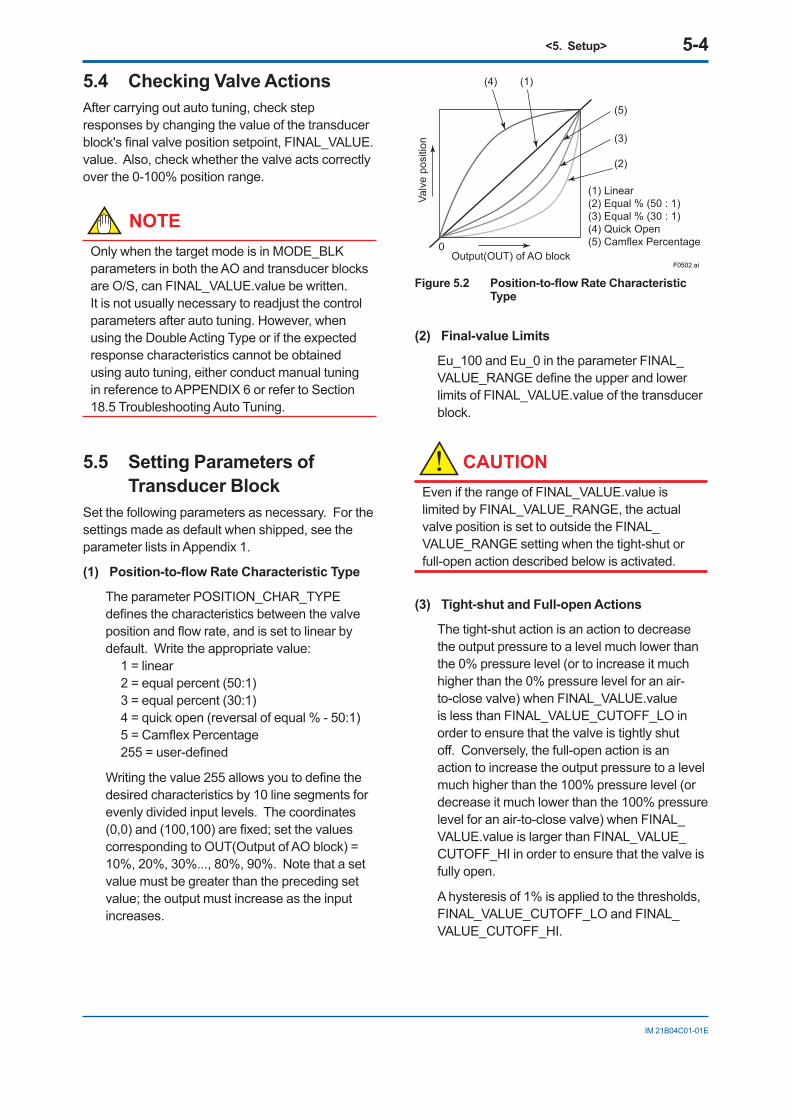
<5. Setup> 5-4
IM 21B04C01-01E
5.4 Checking Valve ActionsAfter carrying out auto tuning, check step responses by changing the value of the transducer block's final valve position setpoint, FINAL_VALUE.value. Also, check whether the valve acts correctly over the 0-100% position range.
NOTEOnly when the target mode is in MODE_BLK parameters in both the AO and transducer blocks are O/S, can FINAL_VALUE.value be written. It is not usually necessary to readjust the control parameters after auto tuning. However, when using the Double Acting Type or if the expected response characteristics cannot be obtained using auto tuning, either conduct manual tuning in reference to APPENDIX 6 or refer to Section 18.5 Troubleshooting Auto Tuning.
5.5 Setting Parameters of Transducer Block
Set the following parameters as necessary. For the settings made as default when shipped, see the parameter lists in Appendix 1.
(1) Position-to-flow Rate Characteristic Type
The parameter POSITION_CHAR_TYPE defines the characteristics between the valve position and flow rate, and is set to linear by default. Write the appropriate value: 1 = linear 2 = equal percent (50:1) 3 = equal percent (30:1) 4 = quick open (reversal of equal % - 50:1) 5 = Camflex Percentage 255 = user-defined
Writing the value 255 allows you to define the desired characteristics by 10 line segments for evenly divided input levels. The coordinates (0,0) and (100,100) are fixed; set the values corresponding to OUT(Output of AO block) = 10%, 20%, 30%..., 80%, 90%. Note that a set value must be greater than the preceding set value; the output must increase as the input increases.
F0502.ai
(1)(4)
0Output(OUT) of AO block
Valv
e po
sitio
n (3)
(2)
(5)
(1) Linear(2) Equal % (50 : 1)(3) Equal % (30 : 1)(4) Quick Open(5) Camflex Percentage
Figure 5.2 Position-to-flow Rate Characteristic Type
(2) Final-value Limits
Eu_100 and Eu_0 in the parameter FINAL_VALUE_RANGE define the upper and lower limits of FINAL_VALUE.value of the transducer block.
CAUTIONEven if the range of FINAL_VALUE.value is limited by FINAL_VALUE_RANGE, the actual valve position is set to outside the FINAL_VALUE_RANGE setting when the tight-shut or full-open action described below is activated.
(3) Tight-shut and Full-open Actions
The tight-shut action is an action to decrease the output pressure to a level much lower than the 0% pressure level (or to increase it much higher than the 0% pressure level for an air-to-close valve) when FINAL_VALUE.value is less than FINAL_VALUE_CUTOFF_LO in order to ensure that the valve is tightly shut off. Conversely, the full-open action is an action to increase the output pressure to a level much higher than the 100% pressure level (or decrease it much lower than the 100% pressure level for an air-to-close valve) when FINAL_VALUE.value is larger than FINAL_VALUE_CUTOFF_HI in order to ensure that the valve is fully open.
A hysteresis of 1% is applied to the thresholds, FINAL_VALUE_CUTOFF_LO and FINAL_VALUE_CUTOFF_HI.
<5. Setup> 5-5
IM 21B04C01-01E
(4) Thresholds for Limit Switches
Just like hardware limit switches for a valve, on/off status signals can be generated when the valve position read-back signal FINAL_POSITION_VALUE.value reaches specified levels. These on/off statuses can be transferred to a DI function block.
Write the threshold for the upper limit switch to LIMSW_HI_LIM, and the threshold for the lower limit switch to LIMSW_LO_LIM.
A hysteresis of 1% is applied to the thresholds, LIMSW_HI_LIM and LIMSW_LO_LIM.
CAUTIONTo make a DI block read the on/off statuses of a limit switch, set CHANNEL of the DI block to:
• 2, for reading the on/off status of the upper limit switch.
• 3, for reading the on/off status of the lower limit switch.
(5) Thresholds for Operation Result Integration Alarms
The YVP110 has a function to integrate the following operation result quantities individually: • TOTAL_CYCLE_COUNT (incremented by 1
at each change in the direction of the action)• TOTAL_TRAVEL (in % where full stroke =
100%)• TOTAL_OPEN_TIME (in hours)• TOTAL_CLOSE_TIME (in hours)• TOTAL_NEAR_CLOSE_TIM (total at nearly
closed time in hours) • SERVO_WARN_COUNT (Total number of
times of Servo output drift warning)
When these values exceed the respective thresholds below, corresponding alarms are output. Set the thresholds as necessary.• CYCLE_COUNT_LIM• TRAVEL_LIM• OPEN_TIME_LIM• CLOSE_TIME_LIM• NEAR_CLOSE_TIME_LIM
Also, set NEAR_CLOSE_THRESHOLD, which defines the threshold of the valve position for counting NEAR_CLOSE_TIME, as necessary.
For other alarms and self-diagnostic functions, see “12.6 Online Diagnostics”.
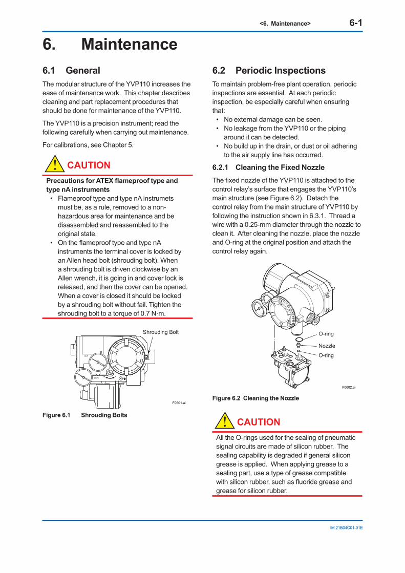
<6. Maintenance> 6-1
IM 21B04C01-01E
6. Maintenance6.1 GeneralThe modular structure of the YVP110 increases the ease of maintenance work. This chapter describes cleaning and part replacement procedures that should be done for maintenance of the YVP110.
The YVP110 is a precision instrument; read the following carefully when carrying out maintenance.
For calibrations, see Chapter 5.
CAUTIONPrecautions for ATEX flameproof type and type nA instruments
• Flameproof type and type nA instrumets must be, as a rule, removed to a non-hazardous area for maintenance and be disassembled and reassembled to the original state.
• On the flameproof type and type nA instruments the terminal cover is locked by an Allen head bolt (shrouding bolt). When a shrouding bolt is driven clockwise by an Allen wrench, it is going in and cover lock is released, and then the cover can be opened.
When a cover is closed it should be locked by a shrouding bolt without fail. Tighten the shrouding bolt to a torque of 0.7 N·m.
Shrouding Bolt
F0601.ai
Figure 6.1 Shrouding Bolts
6.2 Periodic InspectionsTo maintain problem-free plant operation, periodic inspections are essential. At each periodic inspection, be especially careful when ensuring that:
• No external damage can be seen. • No leakage from the YVP110 or the piping
around it can be detected. • No build up in the drain, or dust or oil adhering
to the air supply line has occurred.
6.2.1 Cleaning the Fixed NozzleThe fixed nozzle of the YVP110 is attached to the control relay’s surface that engages the YVP110’s main structure (see Figure 6.2). Detach the control relay from the main structure of YVP110 by following the instruction shown in 6.3.1. Thread a wire with a 0.25-mm diameter through the nozzle to clean it. After cleaning the nozzle, place the nozzle and O-ring at the original position and attach the control relay again.
F0602.ai
Nozzle
O-ring
O-ring
Figure 6.2 Cleaning the Nozzle
CAUTIONAll the O-rings used for the sealing of pneumatic signal circuits are made of silicon rubber. The sealing capability is degraded if general silicon grease is applied. When applying grease to a sealing part, use a type of grease compatible with silicon rubber, such as fluoride grease and grease for silicon rubber.
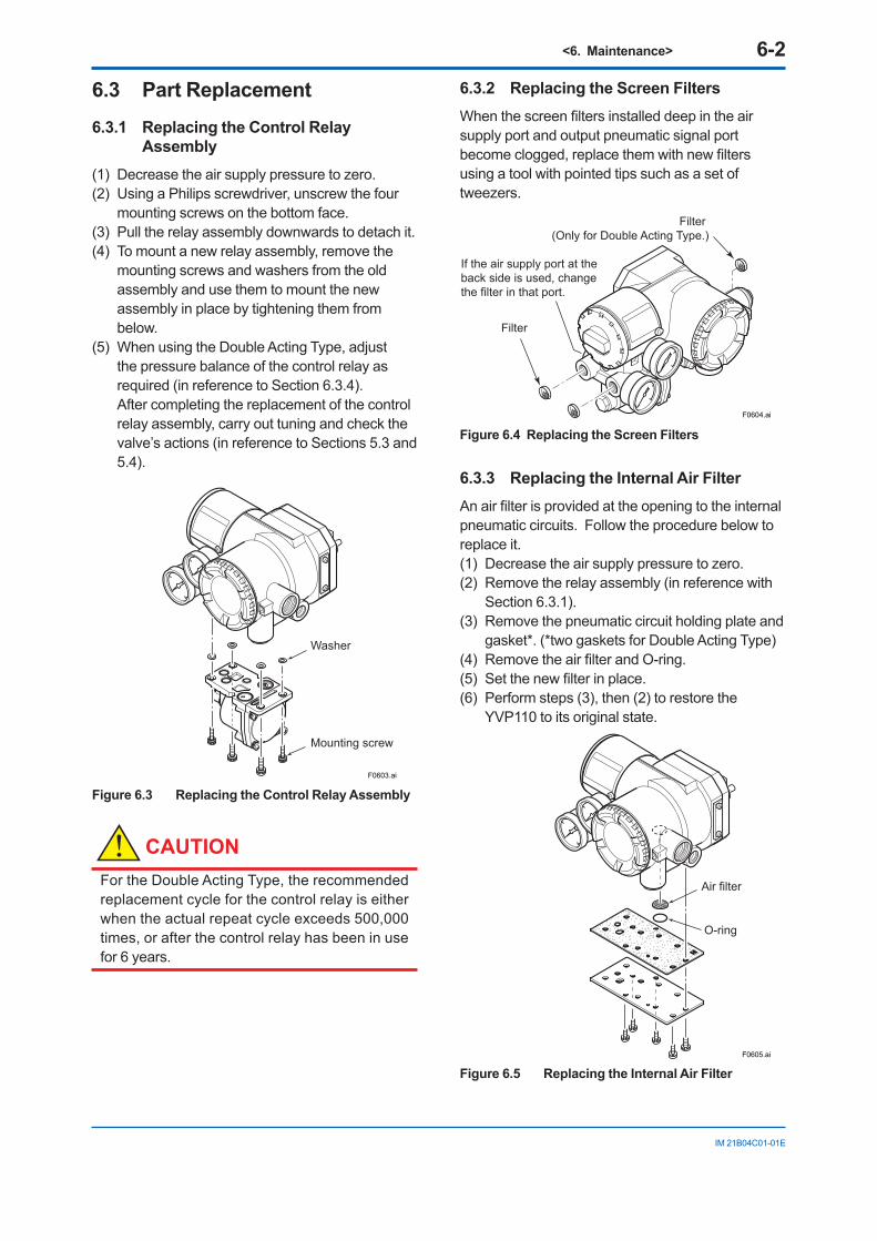
<6. Maintenance> 6-2
IM 21B04C01-01E
6.3 Part Replacement6.3.1 Replacing the Control Relay
Assembly(1) Decrease the air supply pressure to zero. (2) Using a Philips screwdriver, unscrew the four
mounting screws on the bottom face. (3) Pull the relay assembly downwards to detach it. (4) To mount a new relay assembly, remove the
mounting screws and washers from the old assembly and use them to mount the new assembly in place by tightening them from below.
(5) When using the Double Acting Type, adjust the pressure balance of the control relay as required (in reference to Section 6.3.4). After completing the replacement of the control relay assembly, carry out tuning and check the valve’s actions (in reference to Sections 5.3 and 5.4).
F0603.ai
Washer
Mounting screw
Figure 6.3 Replacing the Control Relay Assembly
CAUTIONFor the Double Acting Type, the recommended replacement cycle for the control relay is either when the actual repeat cycle exceeds 500,000 times, or after the control relay has been in use for 6 years.
6.3.2 Replacing the Screen Filters When the screen filters installed deep in the air supply port and output pneumatic signal port become clogged, replace them with new filters using a tool with pointed tips such as a set of tweezers.
F0604.ai
Filter
Filter (Only for Double Acting Type.)
If the air supply port at the back side is used, change the filter in that port.
Figure 6.4 Replacing the Screen Filters
6.3.3 Replacing the Internal Air FilterAn air filter is provided at the opening to the internal pneumatic circuits. Follow the procedure below to replace it. (1) Decrease the air supply pressure to zero. (2) Remove the relay assembly (in reference with
Section 6.3.1). (3) Remove the pneumatic circuit holding plate and
gasket*. (*two gaskets for Double Acting Type)(4) Remove the air filter and O-ring.(5) Set the new filter in place.(6) Perform steps (3), then (2) to restore the
YVP110 to its original state.
F0605.ai
Air filter
O-ring
Figure 6.5 Replacing the Internal Air Filter
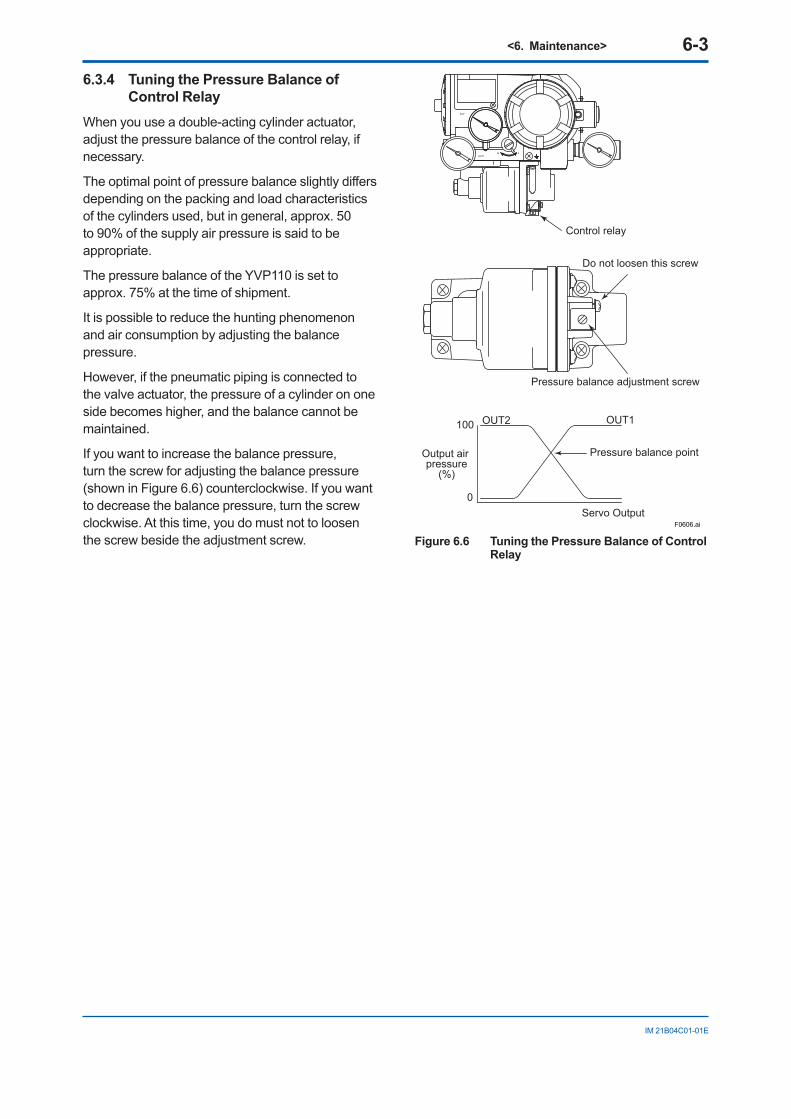
<6. Maintenance> 6-3
IM 21B04C01-01E
6.3.4 Tuning the Pressure Balance of Control Relay
When you use a double-acting cylinder actuator, adjust the pressure balance of the control relay, if necessary.
The optimal point of pressure balance slightly differs depending on the packing and load characteristics of the cylinders used, but in general, approx. 50 to 90% of the supply air pressure is said to be appropriate.
The pressure balance of the YVP110 is set to approx. 75% at the time of shipment.
It is possible to reduce the hunting phenomenon and air consumption by adjusting the balance pressure.
However, if the pneumatic piping is connected to the valve actuator, the pressure of a cylinder on one side becomes higher, and the balance cannot be maintained.
If you want to increase the balance pressure, turn the screw for adjusting the balance pressure (shown in Figure 6.6) counterclockwise. If you want to decrease the balance pressure, turn the screw clockwise. At this time, you do must not to loosen the screw beside the adjustment screw.
Do not loosen this screw
100
0
OUT1OUT2
Pressure balance pointOutput air pressure
(%)
Servo Output
SUP
OUT1AM
Control relay
Pressure balance adjustment screw
F0606.ai
Figure 6.6 Tuning the Pressure Balance of Control Relay
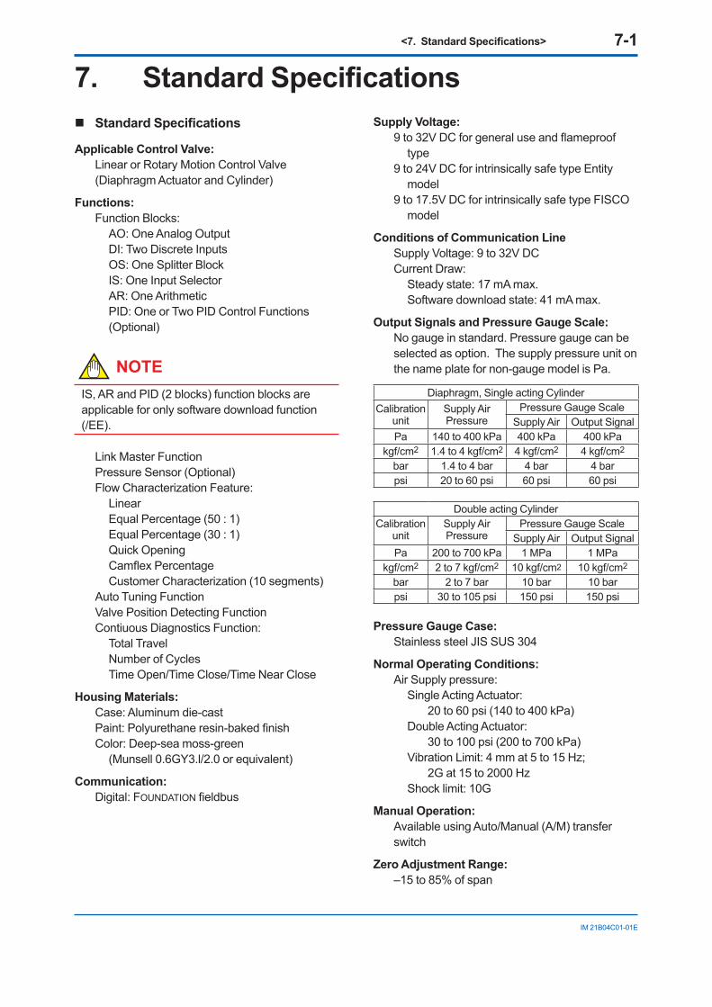
<7. Standard Specifications> 7-1
IM 21B04C01-01E
7. Standard Specifications Standard Specifications
Applicable Control Valve:Linear or Rotary Motion Control Valve (Diaphragm Actuator and Cylinder)
Functions:Function Blocks:
AO: One Analog OutputDI: Two Discrete InputsOS: One Splitter BlockIS: One Input SelectorAR: One ArithmeticPID: One or Two PID Control Functions (Optional)
NOTEIS, AR and PID (2 blocks) function blocks are applicable for only software download function (/EE).
Link Master FunctionPressure Sensor (Optional)Flow Characterization Feature:
LinearEqual Percentage (50 : 1)Equal Percentage (30 : 1)Quick OpeningCamflex PercentageCustomer Characterization (10 segments)
Auto Tuning FunctionValve Position Detecting FunctionContiuous Diagnostics Function:
Total TravelNumber of CyclesTime Open/Time Close/Time Near Close
Housing Materials:Case: Aluminum die-castPaint: Polyurethane resin-baked finishColor: Deep-sea moss-green
(Munsell 0.6GY3.l/2.0 or equivalent)
Communication:Digital: FOUNDATION fieldbus
Supply Voltage:9 to 32V DC for general use and flameproof
type9 to 24V DC for intrinsically safe type Entity
model9 to 17.5V DC for intrinsically safe type FISCO
model
Conditions of Communication LineSupply Voltage: 9 to 32V DCCurrent Draw:
Steady state: 17 mA max.Software download state: 41 mA max.
Output Signals and Pressure Gauge Scale:No gauge in standard. Pressure gauge can be selected as option. The supply pressure unit on the name plate for non-gauge model is Pa.
Diaphragm, Single acting CylinderCalibration
unitSupply Air Pressure
Pressure Gauge ScaleSupply Air Output Signal
Pa 140 to 400 kPa 400 kPa 400 kPakgf/cm2 1.4 to 4 kgf/cm2 4 kgf/cm2 4 kgf/cm2
bar 1.4 to 4 bar 4 bar 4 barpsi 20 to 60 psi 60 psi 60 psi
Double acting CylinderCalibration
unitSupply Air Pressure
Pressure Gauge ScaleSupply Air Output Signal
Pa 200 to 700 kPa 1 MPa 1 MPakgf/cm2 2 to 7 kgf/cm2 10 kgf/cm2 10 kgf/cm2
bar 2 to 7 bar 10 bar 10 barpsi 30 to 105 psi 150 psi 150 psi
Pressure Gauge Case:Stainless steel JIS SUS 304
Normal Operating Conditions:Air Supply pressure:
Single Acting Actuator: 20 to 60 psi (140 to 400 kPa)
Double Acting Actuator: 30 to 100 psi (200 to 700 kPa)
Vibration Limit: 4 mm at 5 to 15 Hz; 2G at 15 to 2000 Hz
Shock limit: 10G
Manual Operation:Available using Auto/Manual (A/M) transfer switch
Zero Adjustment Range:–15 to 85% of span
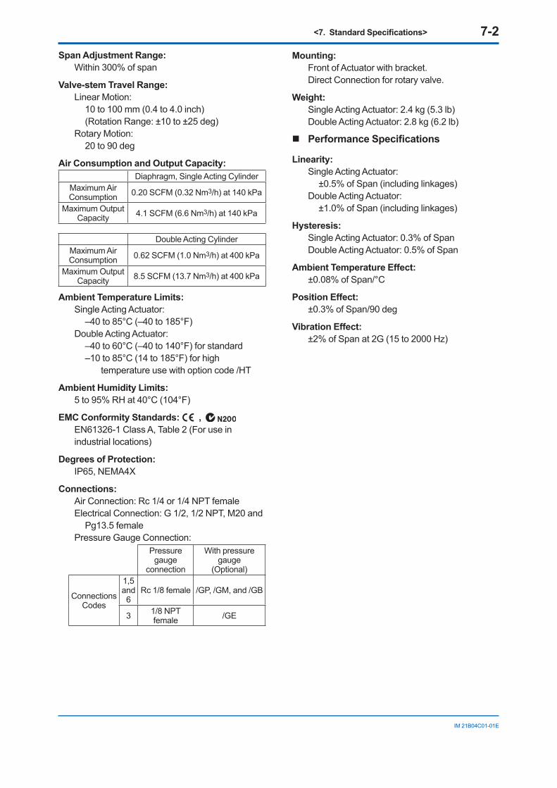
<7. Standard Specifications> 7-2
IM 21B04C01-01E
Span Adjustment Range:Within 300% of span
Valve-stem Travel Range:Linear Motion:
10 to 100 mm (0.4 to 4.0 inch)(Rotation Range: ±10 to ±25 deg)
Rotary Motion:20 to 90 deg
Air Consumption and Output Capacity:Diaphragm, Single Acting Cylinder
Maximum Air Consumption 0.20 SCFM (0.32 Nm3/h) at 140 kPa
Maximum Output Capacity 4.1 SCFM (6.6 Nm3/h) at 140 kPa
Double Acting CylinderMaximum Air Consumption 0.62 SCFM (1.0 Nm3/h) at 400 kPa
Maximum Output Capacity 8.5 SCFM (13.7 Nm3/h) at 400 kPa
Ambient Temperature Limits:Single Acting Actuator:
–40 to 85°C (–40 to 185°F) Double Acting Actuator:
–40 to 60°C (–40 to 140°F) for standard–10 to 85°C (14 to 185°F) for high
temperature use with option code /HT
Ambient Humidity Limits:5 to 95% RH at 40°C (104°F)
EMC Conformity Standards: , EN61326-1 Class A, Table 2 (For use in industrial locations)
Degrees of Protection:IP65, NEMA4X
Connections:Air Connection: Rc 1/4 or 1/4 NPT femaleElectrical Connection: G 1/2, 1/2 NPT, M20 and
Pg13.5 female Pressure Gauge Connection:
Pressure gauge
connection
With pressure gauge
(Optional)
Connections Codes
1,5 and 6
Rc 1/8 female /GP, /GM, and /GB
3 1/8 NPT female /GE
Mounting:Front of Actuator with bracket.Direct Connection for rotary valve.
Weight:Single Acting Actuator: 2.4 kg (5.3 lb)Double Acting Actuator: 2.8 kg (6.2 lb)
Performance Specifications
Linearity:Single Acting Actuator:
±0.5% of Span (including linkages)Double Acting Actuator:
±1.0% of Span (including linkages)
Hysteresis:Single Acting Actuator: 0.3% of SpanDouble Acting Actuator: 0.5% of Span
Ambient Temperature Effect:±0.08% of Span/°C
Position Effect:±0.3% of Span/90 deg
Vibration Effect:±2% of Span at 2G (15 to 2000 Hz)
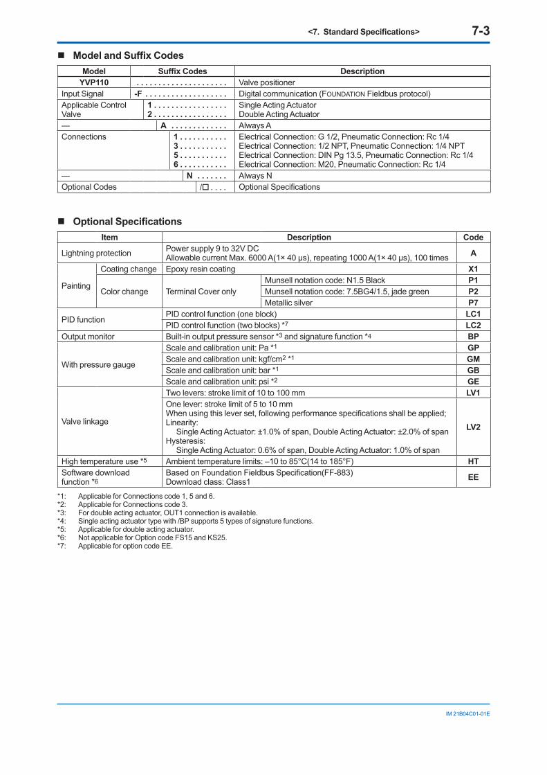
<7. Standard Specifications> 7-3
IM 21B04C01-01E
Model and Suffix CodesModel Suffix Codes Description
YVP110 . . . . . . . . . . . . . . . . . . . . . Valve positionerInput Signal -F . . . . . . . . . . . . . . . . . . . Digital communication (FOUNDATION Fieldbus protocol)Applicable Control Valve
1 . . . . . . . . . . . . . . . . .2 . . . . . . . . . . . . . . . . .
Single Acting ActuatorDouble Acting Actuator
— A . . . . . . . . . . . . . Always AConnections 1 . . . . . . . . . . .
3 . . . . . . . . . . .5 . . . . . . . . . . .6 . . . . . . . . . . .
Electrical Connection: G 1/2, Pneumatic Connection: Rc 1/4Electrical Connection: 1/2 NPT, Pneumatic Connection: 1/4 NPTElectrical Connection: DIN Pg 13.5, Pneumatic Connection: Rc 1/4Electrical Connection: M20, Pneumatic Connection: Rc 1/4
— N . . . . . . . Always NOptional Codes / . . . . Optional Specifications
Optional SpecificationsItem Description Code
Lightning protection Power supply 9 to 32V DCAllowable current Max. 6000 A(1× 40 μs), repeating 1000 A(1× 40 μs), 100 times A
Painting
Coating change Epoxy resin coating X1
Color change Terminal Cover onlyMunsell notation code: N1.5 Black P1Munsell notation code: 7.5BG4/1.5, jade green P2Metallic silver P7
PID functionPID control function (one block) LC1PID control function (two blocks) *7 LC2
Output monitor Built-in output pressure sensor *3 and signature function *4 BP
With pressure gauge
Scale and calibration unit: Pa *1 GPScale and calibration unit: kgf/cm2 *1 GMScale and calibration unit: bar *1 GBScale and calibration unit: psi *2 GE
Valve linkage
Two levers: stroke limit of 10 to 100 mm LV1One lever: stroke limit of 5 to 10 mmWhen using this lever set, following performance specifications shall be applied;Linearity: Single Acting Actuator: ±1.0% of span, Double Acting Actuator: ±2.0% of span
Hysteresis: Single Acting Actuator: 0.6% of span, Double Acting Actuator: 1.0% of span
LV2
High temperature use *5 Ambient temperature limits: –10 to 85°C(14 to 185°F) HTSoftware download function *6
Based on Foundation Fieldbus Specification(FF-883)Download class: Class1 EE
*1: Applicable for Connections code 1, 5 and 6.*2: Applicable for Connections code 3.*3: For double acting actuator, OUT1 connection is available.*4: Single acting actuator type with /BP supports 5 types of signature functions.*5: Applicable for double acting actuator.*6: Not applicable for Option code FS15 and KS25.*7: Applicable for option code EE.
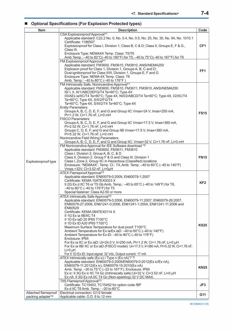
<7. Standard Specifications> 7-4
IM 21B04C01-01E
Optional Specifications (For Explosion Protected types)Item Description Code
Explosionproof type
CSA Explosionproof Approval*1
Applicable standard: C22.2 No. 0, No. 0.4, No. 0.5, No. 25, No. 30, No. 94, No. 1010.1Certificate: 1186507Explosionproof for Class I, Division 1, Class B, C & D; Class II, Groups E, F & G., Class III.Enclosure Type: NEMA4X Temp. Class: T5/T6Amb.Temp.: –40 to 82°C(–40 to 180°F) for T5, –40 to 75°C(–40 to 167°F) for T6
CF1
FM Explosionproof Approval*1
Applicable standard: FM3600, FM3615, FM3810, ANSI/NEMA250Explosion proof for Class 1, Division 1, Groups A, B, C and D;Dust-ignitionproof for Class II/III, Division 1, Groups E, F and GEnclosure Type: NEMA 4X Temp. Class: T6Amb. Temp.: –40 to 80°C (–40 to 176°F )
FF1
FM Intrinsically Safe, Nonincendive Approval*1
Applicable standard: FM3600, FM3610, FM3611, FM3810, ANSI/NEMA250IS/ I, II, III/1/ABCDEFG/T4 Ta=60°C; Type 4XI/0/AEx ia/IIC/T4 Ta=60°C; Type 4X, NI/I/2/ABCD/T4 Ta=60°C; Type 4X, I/2/IIC/T4Ta=60°C; Type 4X, S/II/2/FG/T4Ta=60°C; Type 4X, S/III/2/T4 Ta=60°C; Type 4X
Entity Parameters:Groups A, B, C, D, E, F, and G and Group IIC Vmax=24 V, Imax=250 mA,Pi=1.2 W, Ci=1.76 nF, Li=0 mH
FISCO Parameters:Groups A, B, C, D, E, F, and G and Group IIC Vmax=17.5 V, Imax=360 mA,Pi=2.52 W, Ci=1.76 nF, Li=0 mHGroups C, D, E, F, and G and Group IIB Vmax=17.5 V, Imax=380 mA,Pi=5.32 W, Ci=1.76 nF, Li=0 mH
Nonincendive Field Wiring Parameters:Groups A, B, C, D, E, F, and G and Group IIC: Vmax=32 V, Ci=1.76 nF, Li=0 mH
FS15
FM Nonincendive Approval for /EE Software download *5
Applicable standard: FM3600, FM3611, FM3810Class I, Division 2, Group A, B, C, & DClass II, Division 2, Group F & G and Class III, Division 1Class I, Zone 2, Group IIC in Hazardous (Classified) locationsEnclosure: “NEMA4X”, Temp. CI.: T4, Amb. Temp. –40 to 60°C (–40 to 140°F)Vmax.=32V, Ci=3.52 nF, Li=0μH
FN15
ATEX Flameproof Approval*2
Applicable standard: EN60079-0:2009, EN60079-1:2007Certificate: KEMA 10ATEX0023 XII 2G Ex d IIC T6 or T5 Gb Amb. Temp.: –40 to 65°C (–40 to 149°F) for T6,–40 to 80°C (–40 to 176°F) for T5Special fastener: Class A2-50 or more
KF2
ATEX Intrinsically Safe Approval*2
Applicable standard: EN60079-0:2006, EN60079-11:2007, EN60079-26:2007,EN60079-27:2006, EN61241-0:2006, EN61241-1:2004, EN61241-11:2006 and EN60529Certificate: KEMA 08ATEX0114 XII 1G Ex ia IIB/IIC T4II 1D Ex iaD 20 IP65 T100°CII 1D Ex tD A20 IP65 T100°CMaximum Surface Temperature for dust proof: T100°CAmbient Temperature for Ex ia/Ex iaD: –40 to 60°C (–40 to 140°F)Ambient Temperature for Ex tD: –40 to 80°C (–40 to 176°F)Enclosure: IP65For Ex ia IIC or Ex iaD: Ui=24.0 V, Ii=250 mA, Pi=1.2 W, Ci=1.76 nF, Li=0 μHFor Ex ia IIB/ IIC or Ex iaD (FISCO model): Ui=17.5 V, Ii=380 mA, Pi=5.32 W, Ci=1.76 nF, Li=0 μHFor II 1D Ex tD: Input signal: 32 Vdc, Output current: 17 mA
KS25
ATEX Intrinsically safe (Ex ic) / Type n (Ex nA)*2 *5
Applicable standard: EN60079-0:2009/EN60079-0:2012(Ex ic/Ex nA), EN60079-11:2012(Ex ic), EN60079-15:2010(Ex nA)Amb. Temp: –30 to 75°C (–22 to 167°F), Enclosure: IP65Ex ic: II 3G Ex ic IIC T4 Gc (Intrinsically safe) Ui=32 V, Ci=3.52 nF, Li=0 μHEx nA: II 3G Ex nA IIC T4 Gc (Non-sparking) 32 V DC MAX.
KN25
TIIS Flameproof Approval*3
Certificate: TC15453, TC15452 for option code /BPEx d IIC T6 Amb. Temp.: –20 to 60°C
JF3
Attached flameproofpacking adapter*4
Electrical connection: G1/2 femaleApplicable cable: O.D. 8 to 12 mm G11
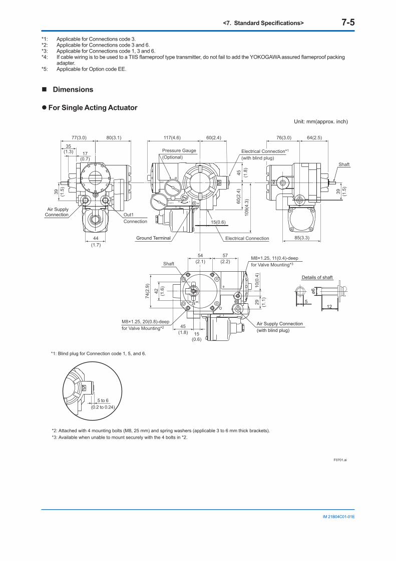
<7. Standard Specifications> 7-5
IM 21B04C01-01E
*1: Applicable for Connections code 3.*2: Applicable for Connections code 3 and 6.*3: Applicable for Connections code 1, 3 and 6.*4: If cable wiring is to be used to a TIIS flameproof type transmitter, do not fail to add the YOKOGAWA assured flameproof packing
adapter.*5: Applicable for Option code EE.
Dimensions
l For Single Acting Actuator
Unit: mm(approx. inch)
F0701.ai
*2: Attached with 4 mounting bolts (M8, 25 mm) and spring washers (applicable 3 to 6 mm thick brackets).*3: Available when unable to mount securely with the 4 bolts in *2.
5 to 6(0.2 to 0.24)
*1: Blind plug for Connection code 1, 5, and 6.
Details of shaft
512
ø6
85(3.3)
77(3.0) 80(3.1)
35(1.3) 17
(0.7)
109(
4.3)
45 (1.8
)60
(2.4
)
117(4.6) 76(3.0) 64(2.5)
44(1.7)
60(2.4)
39 (1.5
)
39 (1.5
)
42 (1.6
)
45(1.8) 15
(0.6)
74(2
.9)
54(2.1)
57(2.2)
10(0
.4)
29 (1.1
)
M8×1.25, 20(0.8)-deepfor Valve Mounting*2
M8×1.25, 11(0.4)-deepfor Valve Mounting*3
Out1 Connection
Pressure Gauge(Optional)
Electrical Connection
Shaft
Shaft
Air SupplyConnection
Air Supply Connection(with blind plug)
15(0.6)
Electrical Connection*1
(with blind plug)
24
Ground Terminal
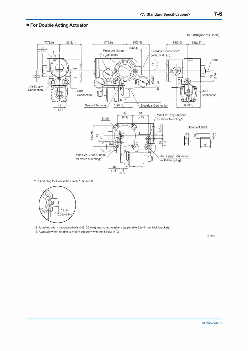
<7. Standard Specifications> 7-6
IM 21B04C01-01E
l For Double Acting Actuator
*2: Attached with 4 mounting bolts (M8, 25 mm) and spring washers (applicable 3 to 6 mm thick brackets).*3: Available when unable to mount securely with the 4 bolts in *2.
5 to 6(0.2 to 0.24)
*1: Blind plug for Connection code 1, 5, and 6.
512
ø6
Details of shaft
85(3.3)
77(3.0) 80(3.1)
35(1.3) 17
(0.7)
110(
4.3)
45 (1.8
)60
(2.4
)
117(4.6) 76(3.0) 64(2.5)
44(1.7)
60(2.4)
88(3.5)
39 (1.5
)
39 (1.5
)
42 (1.6
)
45(1.8) 15
(0.6)
74(2
.9)
54(2.1)
57(2.2)
10(0
.4)
29 (1.1
)
M8×1.25, 20(0.8)-deepfor Valve Mounting*2
M8×1.25, 11(0.4)-deepfor Valve Mounting*3
Out1 Connection
Pressure Gauge (Optional)
Electrical Connection
Shaft
Shaft
Out2Connection
Air SupplyConnection
Air Supply Connection(with blind plug)
15(0.6)
Electrical Connection*1
(with blind plug)
24
Ground Terminal
Unit: mm(approx. inch)
F0702.ai
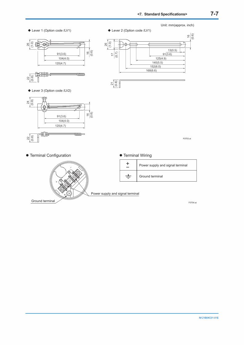
<7. Standard Specifications> 7-7
IM 21B04C01-01E
F0703.ai
22 (0.8
)22 (0.8
)
91(3.6)
26 (1.0
)24 (0.9
)
16 (0.6
)16 (0.6
)
120(4.7)
104(4.0)
91(3.6)
120(4.7)
104(4.0)
21 (0.8
)
168(6.6)
13(0.5)91(3.6)
152(6.0)
125(4.9)140(5.5)
16 (0.6
)
26 (1.0
)17 (0.7
)
Lever 1 (Option code /LV1)
Lever 3 (Option code /LV2)
Lever 2 (Option code /LV1)Unit: mm(approx. inch)
Terminal Wiring Terminal Configuration
+− Power supply and signal terminal
Ground terminal
Ground terminal
Power supply and signal terminal
F0704.ai
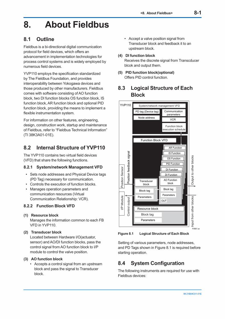
<8. About Fieldbus> 8-1
IM 21B04C01-01E
8. About Fieldbus8.1 OutlineFieldbus is a bi-directional digital communication protocol for field devices, which offers an advancement in implementation technologies for process control systems and is widely employed by numerous field devices.
YVP110 employs the specification standardized by The Fieldbus Foundation, and provides interoperability between Yokogawa devices and those produced by other manufacturers. Fieldbus comes with software consisting of AO function block, two DI function blocks OS function block, IS function block, AR function block and optional PID function block, providing the means to implement a flexible instrumentation system.
For information on other features, engineering, design, construction work, startup and maintenance of Fieldbus, refer to “Fieldbus Technical Information” (TI 38K3A01-01E).
8.2 Internal Structure of YVP110The YVP110 contains two virtual field devices (VFD) that share the following functions.
8.2.1 System/network Management VFD• Sets node addresses and Physical Device tags
(PD Tag) necessary for communication.• Controls the execution of function blocks.• Manages operation parameters and
communication resources (Virtual Communication Relationship: VCR).
8.2.2 Function Block VFD
(1) Resource blockManages the information common to each FB VFD in YVP110.
(2) Transducer blockLocated between Hardware I/O(actuator, sensor) and AO/DI function blocks, pass the control signal from AO function block to I/P module to control the valve position.
(3) AO function block• Accepts a control signal from an upstream
block and pass the signal to Transducer block.
• Accept a valve position signal from Transducer block and feedback it to an upstream block.
(4) DI function blockReceives the discrete signal from Transcducer blcok and output them.
(5) PID function block(optional)Offers PID control function.
8.3 Logical Structure of Each Block
AR Function
IS Function
OS Function
F0801.ai
YVP110
PID Function
DI Function
Function Block VFD
Resource block
DI Function
AO Functionblock
Block tag
OUT
Parameters
Transducerblock
Block tag
Parameters
PD tag (Device tag) Communicationparameters
VCRNode address
Pos
ition
feed
back
sig
nal
Pos
ition
Sen
sor
I/P M
odul
e
Con
trol o
utpu
t
Out
put t
o ot
her b
lock
sIn
put f
rom
oth
er b
lock
s
System/network management VFD
Function blockexecution schedule
Block tag
Parameters
Figure 8.1 Logical Structure of Each Block
Setting of various parameters, node addresses, and PD Tags shown in Figure 8.1 is required before starting operation.
8.4 System ConfigurationThe following instruments are required for use with Fieldbus devices:
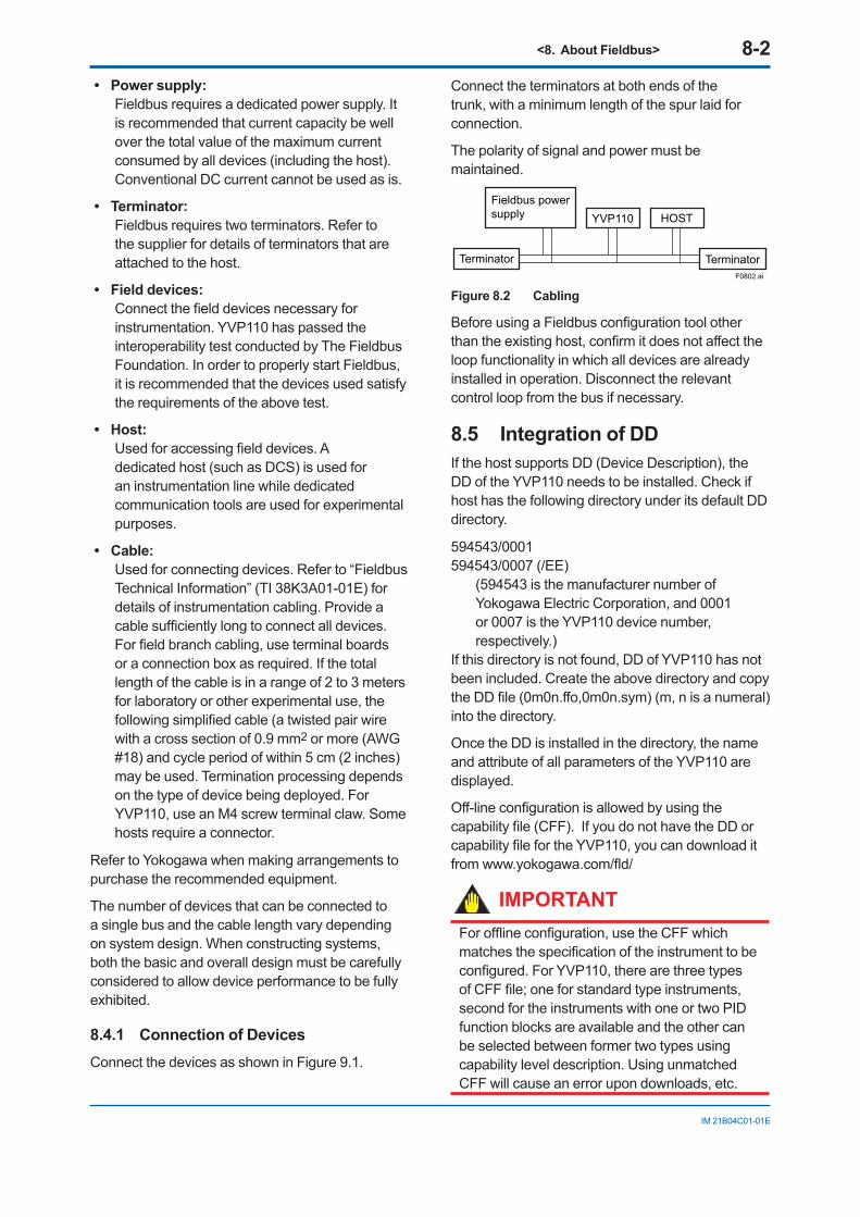
<8. About Fieldbus> 8-2
IM 21B04C01-01E
• Power supply:Fieldbus requires a dedicated power supply. It is recommended that current capacity be well over the total value of the maximum current consumed by all devices (including the host). Conventional DC current cannot be used as is.
• Terminator: Fieldbus requires two terminators. Refer to
the supplier for details of terminators that are attached to the host.
• Field devices: Connect the field devices necessary for
instrumentation. YVP110 has passed the interoperability test conducted by The Fieldbus Foundation. In order to properly start Fieldbus, it is recommended that the devices used satisfy the requirements of the above test.
• Host: Used for accessing field devices. A
dedicated host (such as DCS) is used for an instrumentation line while dedicated communication tools are used for experimental purposes.
• Cable: Used for connecting devices. Refer to “Fieldbus
Technical Information” (TI 38K3A01-01E) for details of instrumentation cabling. Provide a cable sufficiently long to connect all devices. For field branch cabling, use terminal boards or a connection box as required. If the total length of the cable is in a range of 2 to 3 meters for laboratory or other experimental use, the following simplified cable (a twisted pair wire with a cross section of 0.9 mm2 or more (AWG #18) and cycle period of within 5 cm (2 inches) may be used. Termination processing depends on the type of device being deployed. For YVP110, use an M4 screw terminal claw. Some hosts require a connector.
Refer to Yokogawa when making arrangements to purchase the recommended equipment.
The number of devices that can be connected to a single bus and the cable length vary depending on system design. When constructing systems, both the basic and overall design must be carefully considered to allow device performance to be fully exhibited.
8.4.1 Connection of DevicesConnect the devices as shown in Figure 9.1.
Connect the terminators at both ends of the trunk, with a minimum length of the spur laid for connection.
The polarity of signal and power must be maintained.
YVP110Fieldbus power supply
Terminator Terminator
HOST
F0802.ai
Figure 8.2 Cabling
Before using a Fieldbus configuration tool other than the existing host, confirm it does not affect the loop functionality in which all devices are already installed in operation. Disconnect the relevant control loop from the bus if necessary.
8.5 Integration of DDIf the host supports DD (Device Description), the DD of the YVP110 needs to be installed. Check if host has the following directory under its default DD directory.
594543/0001594543/0007 (/EE)
(594543 is the manufacturer number of Yokogawa Electric Corporation, and 0001 or 0007 is the YVP110 device number, respectively.)
If this directory is not found, DD of YVP110 has not been included. Create the above directory and copy the DD file (0m0n.ffo,0m0n.sym) (m, n is a numeral) into the directory.
Once the DD is installed in the directory, the name and attribute of all parameters of the YVP110 are displayed.
Off-line configuration is allowed by using the capability file (CFF). If you do not have the DD or capability file for the YVP110, you can download it from www.yokogawa.com/fld/
IMPORTANTFor offline configuration, use the CFF which matches the specification of the instrument to be configured. For YVP110, there are three types of CFF file; one for standard type instruments, second for the instruments with one or two PID function blocks are available and the other can be selected between former two types using capability level description. Using unmatched CFF will cause an error upon downloads, etc.
<9. Configuration> 9-1
IM 21B04C01-01E
9. ConfigurationThis chapter contains information on how to adapt the function and performance of the YVP110 to suit specific applications. Because two or more devices are connected to Fieldbus, settings including the requirements of all devices need to be determined. Practically, the following steps must be taken.
(1) Network design
Determines the devices to be connected to Fieldbus and checks the capacity of the power supply.
(2) Network definition
Determines the tag and node addresses for all devices.
(3) Definition of combining function blocks
Determines the method for combination between each function block.
(4) Setting tags and addresses
Sets the PD Tag and node addresses one by one for each device.
(5) Communication setting
Sets the link between communication parameters and function blocks.
(6) Block setting
Sets the parameters for function blocks.
The following section describes each step of the procedure in the order given. Using a dedicated configuration tool allows the procedure to be significantly simplified. This section describes the procedure to be assigned for a host which has relatively simple functions. For operation of the host, refer to the instruction manual for each host. No details of the host are explained in the rest of this material.
IMPORTANTConnecting a Fieldbus configuration tool to a loop with its existing host may cause communication data scrambles resulting in a functional disorder or a system failure.
IMPORTANTDo not turn off the power immediately after setting. If the power is turned off within 40 seconds after setting is made, the modified parameters are not saved and the settings return to the original values.
9.1 Network DesignSelect the devices to be connected to the Fieldbus network. (Refer to 8.4 'System Configuration' for selection of the devices.)
First, check the capacity of the power supply. The power supply capacity must be greater than the sum of the maximum current consumed by all devices to be connected to Fieldbus. The maximum current consumed (power supply voltage 9 V to 32 V) for YVP110 is 17 mA. The cable must have the spur in a minimum length with terminators installed at both ends of the trunk.
9.2 Network DefinitionBefore connection of devices with Fieldbus, define the Fieldbus network. Allocate PD Tag and node addresses to all devices (excluding such passive devices as terminators).
The PD Tag is the same as the conventional one used for the device. Up to 32 alphanumeric characters may be used for definition. Use a hyphen as a delimiter as required.
The node address is used to specify devices for communication purposes. Because data is too long for a PD Tag, the host uses the node address in place of the PD Tag for communication. A range of 20 to 247 (or hexadecimal 0x14 to 0xF7) can be set. Generally, the device (LM device) with bus control function (Link Master function) is allocated from a smaller address number (20) side, and other devices (BASIC device) without bus control function allocated from a larger address number (247) side respectively.
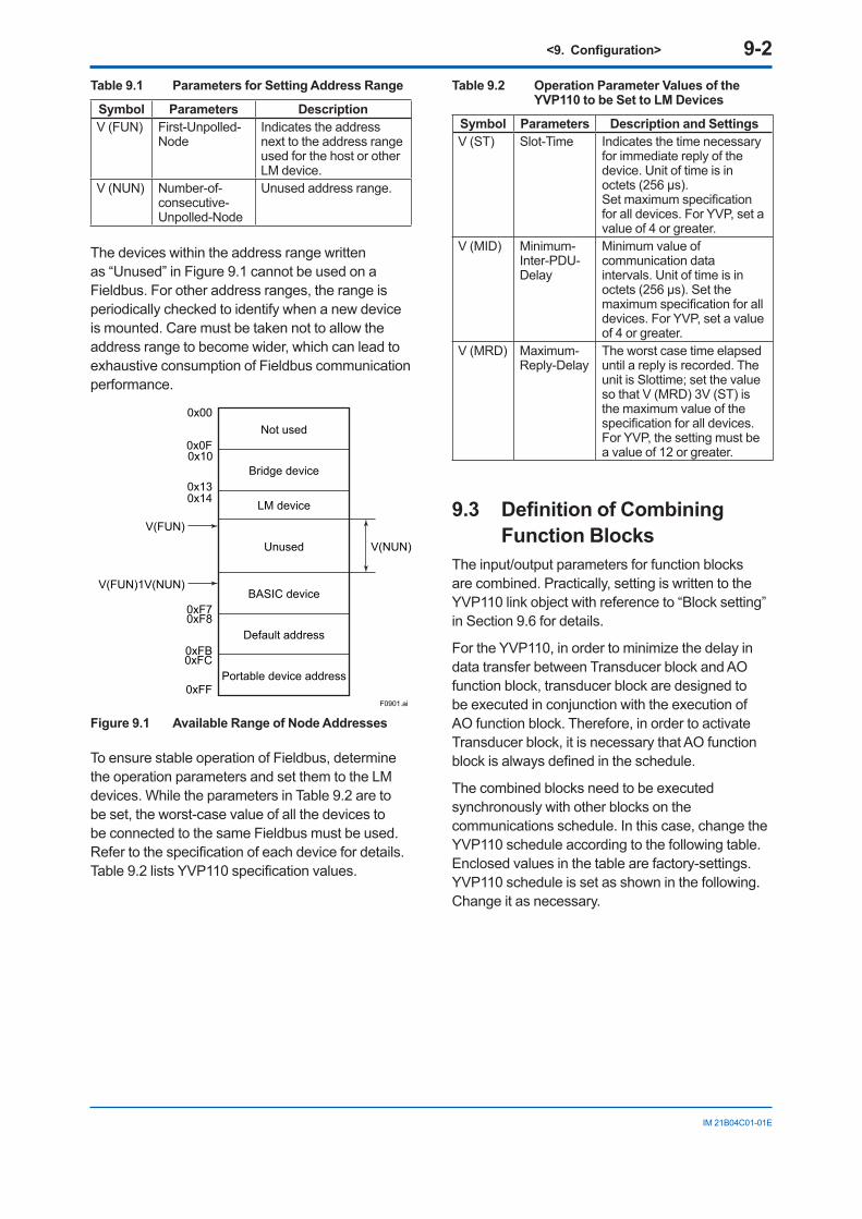
<9. Configuration> 9-2
IM 21B04C01-01E
Table 9.1 Parameters for Setting Address Range
Symbol Parameters DescriptionV (FUN) First-Unpolled-
NodeIndicates the address next to the address range used for the host or other LM device.
V (NUN) Number-of-consecutive-Unpolled-Node
Unused address range.
The devices within the address range written as “Unused” in Figure 9.1 cannot be used on a Fieldbus. For other address ranges, the range is periodically checked to identify when a new device is mounted. Care must be taken not to allow the address range to become wider, which can lead to exhaustive consumption of Fieldbus communication performance.
Bridge device
Not used0x00
0x0F
0x140x13
0x10
0xF70xF8
0xFB0xFC
0xFF
V(FUN)
V(FUN)1V(NUN)
LM device
Unused V(NUN)
BASIC device
Default address
Portable device address
F0901.ai
Figure 9.1 Available Range of Node Addresses
To ensure stable operation of Fieldbus, determine the operation parameters and set them to the LM devices. While the parameters in Table 9.2 are to be set, the worst-case value of all the devices to be connected to the same Fieldbus must be used. Refer to the specification of each device for details. Table 9.2 lists YVP110 specification values.
Table 9.2 Operation Parameter Values of the YVP110 to be Set to LM Devices
Symbol Parameters Description and SettingsV (ST) Slot-Time Indicates the time necessary
for immediate reply of the device. Unit of time is in octets (256 μs).Set maximum specification for all devices. For YVP, set a value of 4 or greater.
V (MID) Minimum-Inter-PDU-Delay
Minimum value of communication data intervals. Unit of time is in octets (256 μs). Set the maximum specification for all devices. For YVP, set a value of 4 or greater.
V (MRD) Maximum-Reply-Delay
The worst case time elapsed until a reply is recorded. The unit is Slottime; set the value so that V (MRD) 3V (ST) is the maximum value of the specification for all devices. For YVP, the setting must be a value of 12 or greater.
9.3 Definition of Combining Function Blocks
The input/output parameters for function blocks are combined. Practically, setting is written to the YVP110 link object with reference to “Block setting” in Section 9.6 for details.
For the YVP110, in order to minimize the delay in data transfer between Transducer block and AO function block, transducer block are designed to be executed in conjunction with the execution of AO function block. Therefore, in order to activate Transducer block, it is necessary that AO function block is always defined in the schedule.
The combined blocks need to be executed synchronously with other blocks on the communications schedule. In this case, change the YVP110 schedule according to the following table. Enclosed values in the table are factory-settings. YVP110 schedule is set as shown in the following. Change it as necessary.
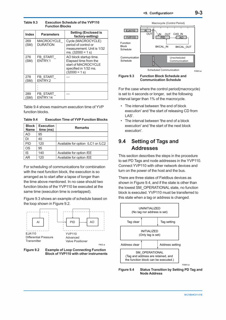
<9. Configuration> 9-3
IM 21B04C01-01E
Table 9.3 Execution Schedule of the YVP110 Function Blocks
Index Parameters Setting (Enclosed isfactory-setting)
269(SM)
MACROCYCLE_DURATION
Cycle (MACROCYCLE) period of control or measurement. Unit is 1/32 ms. (32000 = 1 s)
276(SM)
FB_START_ENTRY.1
AO block startup time.Elapsed time from the start of MACROCYCLE specified in 1/32 ms. (32000 = 1 s)
278(SM)
FB_START_ENTRY.2
—
...289(SM)
FB_START_ENTRY.14
—
Table 9.4 shows maximum execution time of YVP function blocks.
Table 9.4 Execution Time of YVP Function Blocks
BlockName
Executiontime (ms) Remarks
AO 95DI 40PID 120 Available for option /LC1 or /LC2OS 95IS 140 Available for option /EEAR 120 Available for option /EE
For scheduling of communications for combination with the next function block, the execution is so arranged as to start after a lapse of longer than the time above mentioned. In no case should two function blocks of the YVP110 be executed at the same time (execution time is overlapped).
Figure 9.3 shows an example of schedule based on the loop shown in Figure 9.2.
F902.ai
PID
YVP110 Advanced Valve Positioner
AI
EJA110Differential PressureTransmitter
AO
Figure 9.2 Example of Loop Connecting Function Block of YVP110 with other instruments
EJA110 AI
YVP110 PID AO
Function BlockSchedule
CommunicationSchedule
IN
BKCAL_IN BKCAL_OUT
F0903.ai
OUT
Unscheduled Communication
Scheduled Communication
Macrocycle (Control Period)
OUT CAS_IN
Figure 9.3 Function Block Schedule and Communication Schedule
For the case where the control period(macrocycle) is set to 4 seconds or longer, set the following interval larger than 1% of the macrocycle.
• The interval between 'the end of block execution' and 'the start of releasing CD from LAS'.
• The interval between 'the end of a block execution' and 'the start of the next block execution'.
9.4 Setting of Tags and Addresses
This section describes the steps in the procedure to set PD Tags and node addresses in the YVP110. Connect YVP110 with other network devices and turn on the power of the host and the bus.
There are three states of Fieldbus devices as shown in Figure 9.4, and if the state is other than the lowest SM_OPERATIONAL state, no function block is executed. YVP110 must be transferred to this state when a tag or address is changed.
UNINITIALIZED(No tag nor address is set)
Tag clear Tag setting
INITIALIZED(Only tag is set)
SM_OPERATIONAL(Tag and address are retained, and the function block can be executed.)
Address clear
F0904.ai
Address setting
Figure 9.4 Status Transition by Setting PD Tag and Node Address
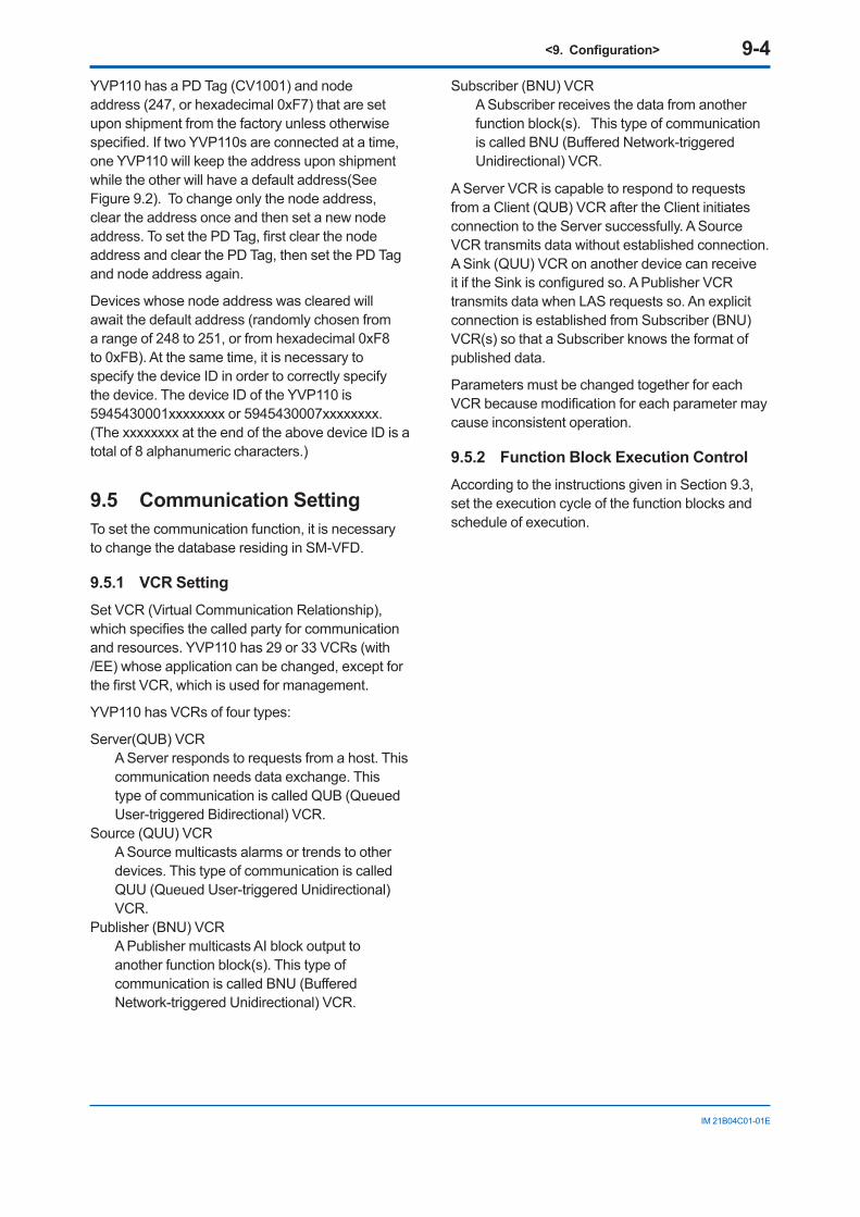
<9. Configuration> 9-4
IM 21B04C01-01E
YVP110 has a PD Tag (CV1001) and node address (247, or hexadecimal 0xF7) that are set upon shipment from the factory unless otherwise specified. If two YVP110s are connected at a time, one YVP110 will keep the address upon shipment while the other will have a default address(See Figure 9.2). To change only the node address, clear the address once and then set a new node address. To set the PD Tag, first clear the node address and clear the PD Tag, then set the PD Tag and node address again.
Devices whose node address was cleared will await the default address (randomly chosen from a range of 248 to 251, or from hexadecimal 0xF8 to 0xFB). At the same time, it is necessary to specify the device ID in order to correctly specify the device. The device ID of the YVP110 is 5945430001xxxxxxxx or 5945430007xxxxxxxx. (The xxxxxxxx at the end of the above device ID is a total of 8 alphanumeric characters.)
9.5 Communication SettingTo set the communication function, it is necessary to change the database residing in SM-VFD.
9.5.1 VCR SettingSet VCR (Virtual Communication Relationship), which specifies the called party for communication and resources. YVP110 has 29 or 33 VCRs (with /EE) whose application can be changed, except for the first VCR, which is used for management.
YVP110 has VCRs of four types:
Server(QUB) VCR A Server responds to requests from a host. This
communication needs data exchange. This type of communication is called QUB (Queued User-triggered Bidirectional) VCR.
Source (QUU) VCR A Source multicasts alarms or trends to other
devices. This type of communication is called QUU (Queued User-triggered Unidirectional) VCR.
Publisher (BNU) VCR A Publisher multicasts AI block output to
another function block(s). This type of communication is called BNU (Buffered Network-triggered Unidirectional) VCR.
Subscriber (BNU) VCR A Subscriber receives the data from another
function block(s). This type of communication is called BNU (Buffered Network-triggered Unidirectional) VCR.
A Server VCR is capable to respond to requests from a Client (QUB) VCR after the Client initiates connection to the Server successfully. A Source VCR transmits data without established connection. A Sink (QUU) VCR on another device can receive it if the Sink is configured so. A Publisher VCR transmits data when LAS requests so. An explicit connection is established from Subscriber (BNU) VCR(s) so that a Subscriber knows the format of published data.
Parameters must be changed together for each VCR because modification for each parameter may cause inconsistent operation.
9.5.2 Function Block Execution ControlAccording to the instructions given in Section 9.3, set the execution cycle of the function blocks and schedule of execution.
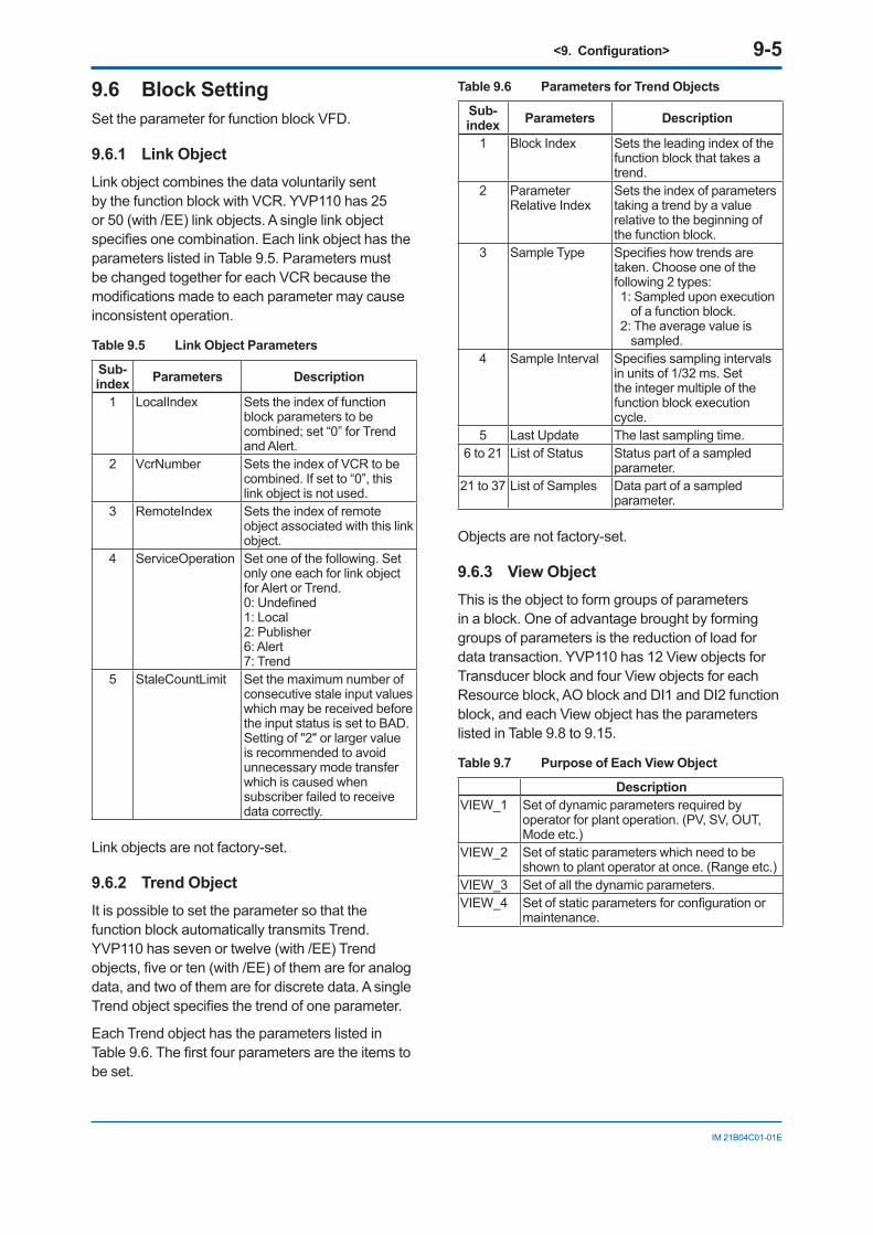
<9. Configuration> 9-5
IM 21B04C01-01E
9.6 Block SettingSet the parameter for function block VFD.
9.6.1 Link ObjectLink object combines the data voluntarily sent by the function block with VCR. YVP110 has 25 or 50 (with /EE) link objects. A single link object specifies one combination. Each link object has the parameters listed in Table 9.5. Parameters must be changed together for each VCR because the modifications made to each parameter may cause inconsistent operation.
Table 9.5 Link Object Parameters
Sub-index Parameters Description
1 LocalIndex Sets the index of function block parameters to be combined; set “0” for Trend and Alert.
2 VcrNumber Sets the index of VCR to be combined. If set to “0”, this link object is not used.
3 RemoteIndex Sets the index of remote object associated with this link object.
4 ServiceOperation Set one of the following. Set only one each for link object for Alert or Trend. 0: Undefined 1: Local 2: Publisher 6: Alert 7: Trend
5 StaleCountLimit Set the maximum number of consecutive stale input values which may be received before the input status is set to BAD.Setting of "2" or larger value is recommended to avoid unnecessary mode transfer which is caused when subscriber failed to receive data correctly.
Link objects are not factory-set.
9.6.2 Trend ObjectIt is possible to set the parameter so that the function block automatically transmits Trend. YVP110 has seven or twelve (with /EE) Trend objects, five or ten (with /EE) of them are for analog data, and two of them are for discrete data. A single Trend object specifies the trend of one parameter.
Each Trend object has the parameters listed in Table 9.6. The first four parameters are the items to be set.
Table 9.6 Parameters for Trend Objects
Sub-index Parameters Description
1 Block Index Sets the leading index of the function block that takes a trend.
2 Parameter Relative Index
Sets the index of parameters taking a trend by a value relative to the beginning of the function block.
3 Sample Type Specifies how trends are taken. Choose one of the following 2 types: 1: Sampled upon execution
of a function block. 2: The average value is
sampled.4 Sample Interval Specifies sampling intervals
in units of 1/32 ms. Set the integer multiple of the function block execution cycle.
5 Last Update The last sampling time.6 to 21 List of Status Status part of a sampled
parameter.21 to 37 List of Samples Data part of a sampled
parameter.
Objects are not factory-set.
9.6.3 View ObjectThis is the object to form groups of parameters in a block. One of advantage brought by forming groups of parameters is the reduction of load for data transaction. YVP110 has 12 View objects for Transducer block and four View objects for each Resource block, AO block and DI1 and DI2 function block, and each View object has the parameters listed in Table 9.8 to 9.15.
Table 9.7 Purpose of Each View Object
DescriptionVIEW_1 Set of dynamic parameters required by
operator for plant operation. (PV, SV, OUT, Mode etc.)
VIEW_2 Set of static parameters which need to be shown to plant operator at once. (Range etc.)
VIEW_3 Set of all the dynamic parameters.VIEW_4 Set of static parameters for configuration or
maintenance.
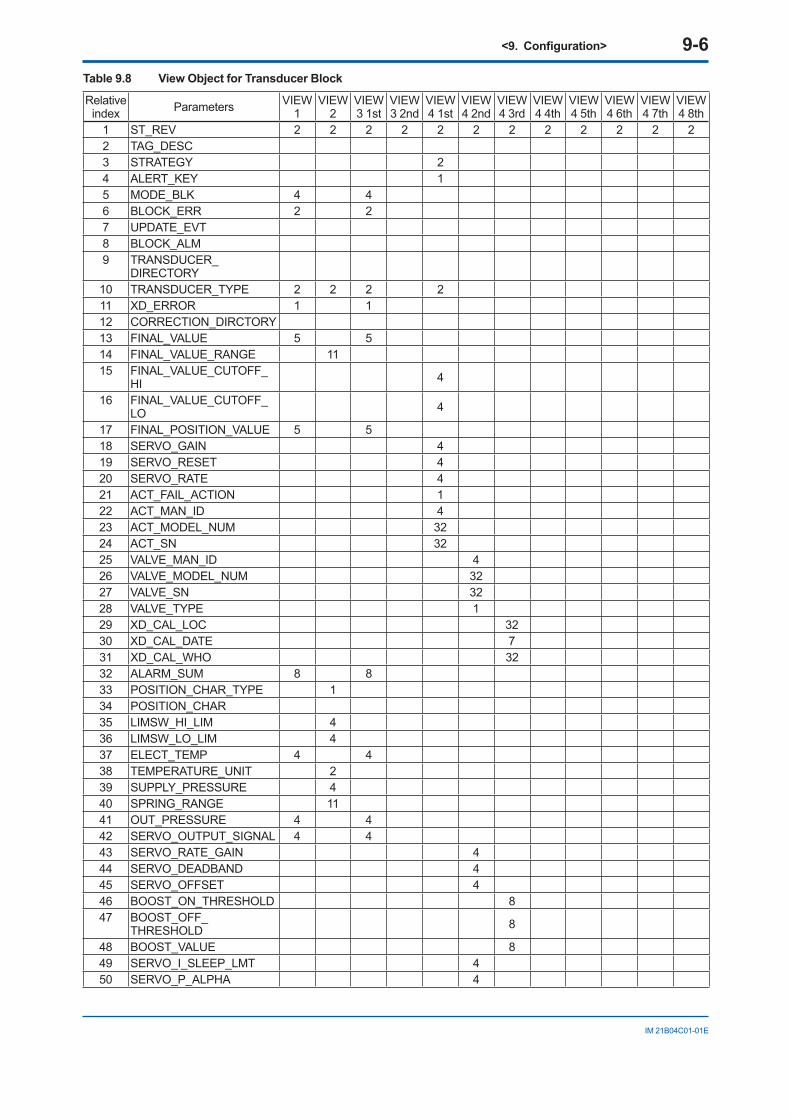
<9. Configuration> 9-6
IM 21B04C01-01E
Table 9.8 View Object for Transducer Block
Relative index Parameters VIEW
1VIEW
2VIEW 3 1st
VIEW 3 2nd
VIEW 4 1st
VIEW 4 2nd
VIEW 4 3rd
VIEW 4 4th
VIEW 4 5th
VIEW 4 6th
VIEW 4 7th
VIEW 4 8th
1 ST_REV 2 2 2 2 2 2 2 2 2 2 2 22 TAG_DESC3 STRATEGY 24 ALERT_KEY 15 MODE_BLK 4 46 BLOCK_ERR 2 27 UPDATE_EVT8 BLOCK_ALM9 TRANSDUCER_
DIRECTORY10 TRANSDUCER_TYPE 2 2 2 211 XD_ERROR 1 112 CORRECTION_DIRCTORY13 FINAL_VALUE 5 514 FINAL_VALUE_RANGE 1115 FINAL_VALUE_CUTOFF_
HI 4
16 FINAL_VALUE_CUTOFF_LO 4
17 FINAL_POSITION_VALUE 5 518 SERVO_GAIN 419 SERVO_RESET 420 SERVO_RATE 421 ACT_FAIL_ACTION 122 ACT_MAN_ID 423 ACT_MODEL_NUM 3224 ACT_SN 3225 VALVE_MAN_ID 426 VALVE_MODEL_NUM 3227 VALVE_SN 3228 VALVE_TYPE 129 XD_CAL_LOC 3230 XD_CAL_DATE 731 XD_CAL_WHO 3232 ALARM_SUM 8 833 POSITION_CHAR_TYPE 134 POSITION_CHAR35 LIMSW_HI_LIM 436 LIMSW_LO_LIM 437 ELECT_TEMP 4 438 TEMPERATURE_UNIT 239 SUPPLY_PRESSURE 440 SPRING_RANGE 1141 OUT_PRESSURE 4 442 SERVO_OUTPUT_SIGNAL 4 443 SERVO_RATE_GAIN 444 SERVO_DEADBAND 445 SERVO_OFFSET 446 BOOST_ON_THRESHOLD 847 BOOST_OFF_
THRESHOLD 8
48 BOOST_VALUE 849 SERVO_I_SLEEP_LMT 450 SERVO_P_ALPHA 4
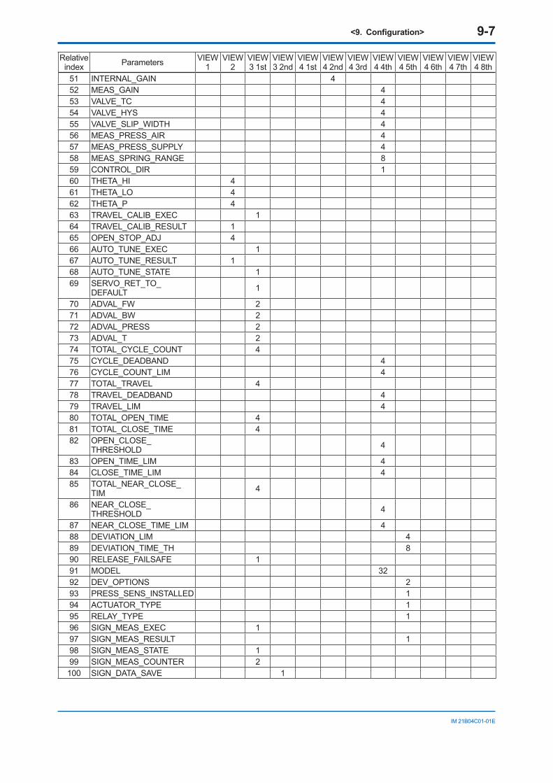
<9. Configuration> 9-7
IM 21B04C01-01E
Relative index Parameters VIEW
1VIEW
2VIEW 3 1st
VIEW 3 2nd
VIEW 4 1st
VIEW 4 2nd
VIEW 4 3rd
VIEW 4 4th
VIEW 4 5th
VIEW 4 6th
VIEW 4 7th
VIEW 4 8th
51 INTERNAL_GAIN 452 MEAS_GAIN 453 VALVE_TC 454 VALVE_HYS 455 VALVE_SLIP_WIDTH 456 MEAS_PRESS_AIR 457 MEAS_PRESS_SUPPLY 458 MEAS_SPRING_RANGE 859 CONTROL_DIR 160 THETA_HI 461 THETA_LO 462 THETA_P 463 TRAVEL_CALIB_EXEC 164 TRAVEL_CALIB_RESULT 165 OPEN_STOP_ADJ 466 AUTO_TUNE_EXEC 167 AUTO_TUNE_RESULT 168 AUTO_TUNE_STATE 169 SERVO_RET_TO_
DEFAULT 1
70 ADVAL_FW 271 ADVAL_BW 272 ADVAL_PRESS 273 ADVAL_T 274 TOTAL_CYCLE_COUNT 475 CYCLE_DEADBAND 476 CYCLE_COUNT_LIM 477 TOTAL_TRAVEL 478 TRAVEL_DEADBAND 479 TRAVEL_LIM 480 TOTAL_OPEN_TIME 481 TOTAL_CLOSE_TIME 482 OPEN_CLOSE_
THRESHOLD 4
83 OPEN_TIME_LIM 484 CLOSE_TIME_LIM 485 TOTAL_NEAR_CLOSE_
TIM 4
86 NEAR_CLOSE_THRESHOLD 4
87 NEAR_CLOSE_TIME_LIM 488 DEVIATION_LIM 489 DEVIATION_TIME_TH 890 RELEASE_FAILSAFE 191 MODEL 3292 DEV_OPTIONS 293 PRESS_SENS_INSTALLED 194 ACTUATOR_TYPE 195 RELAY_TYPE 196 SIGN_MEAS_EXEC 197 SIGN_MEAS_RESULT 198 SIGN_MEAS_STATE 199 SIGN_MEAS_COUNTER 2100 SIGN_DATA_SAVE 1
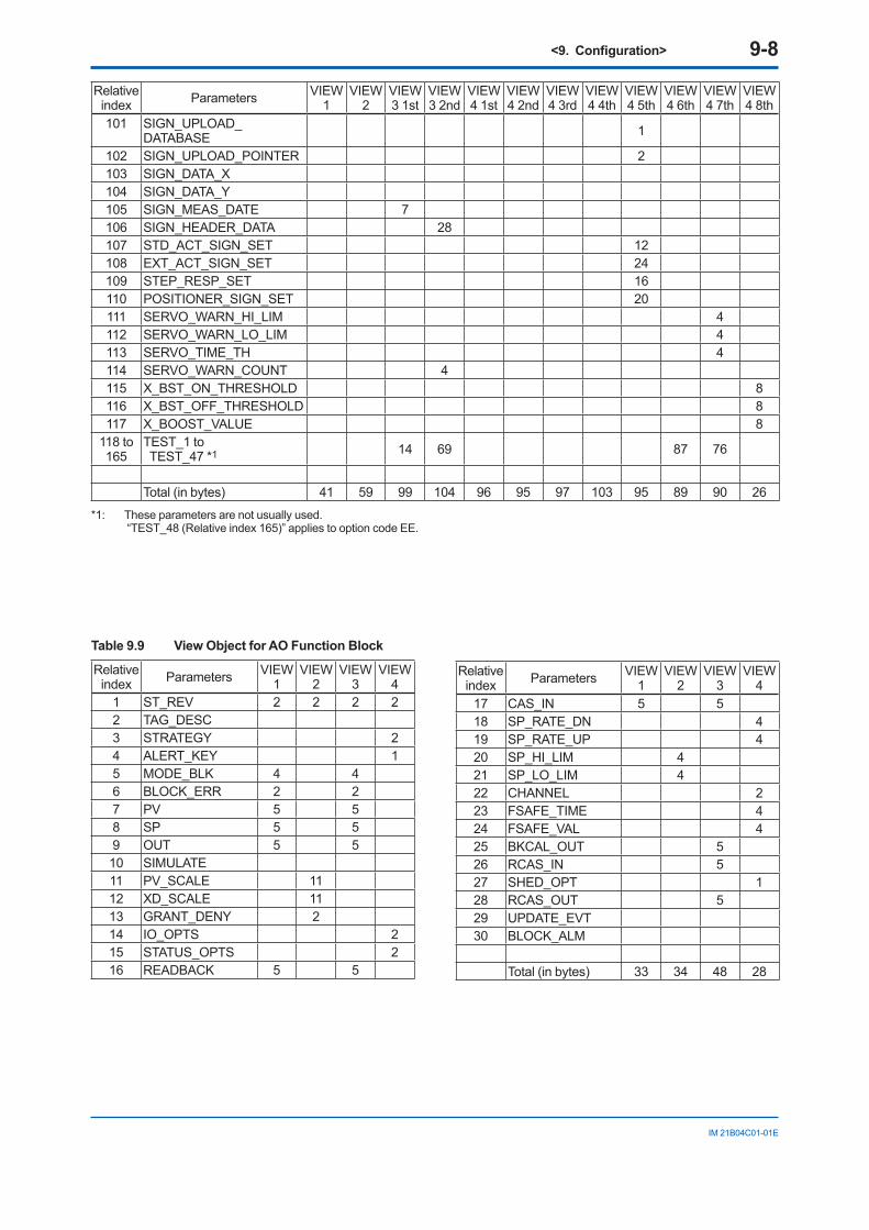
<9. Configuration> 9-8
IM 21B04C01-01E
Relative index Parameters VIEW
1VIEW
2VIEW 3 1st
VIEW 3 2nd
VIEW 4 1st
VIEW 4 2nd
VIEW 4 3rd
VIEW 4 4th
VIEW 4 5th
VIEW 4 6th
VIEW 4 7th
VIEW 4 8th
101 SIGN_UPLOAD_DATABASE 1
102 SIGN_UPLOAD_POINTER 2103 SIGN_DATA_X104 SIGN_DATA_Y105 SIGN_MEAS_DATE 7106 SIGN_HEADER_DATA 28107 STD_ACT_SIGN_SET 12108 EXT_ACT_SIGN_SET 24109 STEP_RESP_SET 16110 POSITIONER_SIGN_SET 20111 SERVO_WARN_HI_LIM 4112 SERVO_WARN_LO_LIM 4113 SERVO_TIME_TH 4114 SERVO_WARN_COUNT 4115 X_BST_ON_THRESHOLD 8116 X_BST_OFF_THRESHOLD 8117 X_BOOST_VALUE 8
118 to 165
TEST_1 to TEST_47 *1 14 69 87 76
Total (in bytes) 41 59 99 104 96 95 97 103 95 89 90 26
*1: These parameters are not usually used. “TEST_48 (Relative index 165)” applies to option code EE.
Table 9.9 View Object for AO Function Block
Relative index Parameters VIEW
1VIEW
2VIEW
3VIEW
41 ST_REV 2 2 2 22 TAG_DESC3 STRATEGY 24 ALERT_KEY 15 MODE_BLK 4 46 BLOCK_ERR 2 27 PV 5 58 SP 5 59 OUT 5 510 SIMULATE11 PV_SCALE 1112 XD_SCALE 1113 GRANT_DENY 214 IO_OPTS 215 STATUS_OPTS 216 READBACK 5 5
Relative index Parameters VIEW
1VIEW
2VIEW
3VIEW
417 CAS_IN 5 518 SP_RATE_DN 419 SP_RATE_UP 420 SP_HI_LIM 421 SP_LO_LIM 422 CHANNEL 223 FSAFE_TIME 424 FSAFE_VAL 425 BKCAL_OUT 526 RCAS_IN 527 SHED_OPT 128 RCAS_OUT 529 UPDATE_EVT30 BLOCK_ALM
Total (in bytes) 33 34 48 28
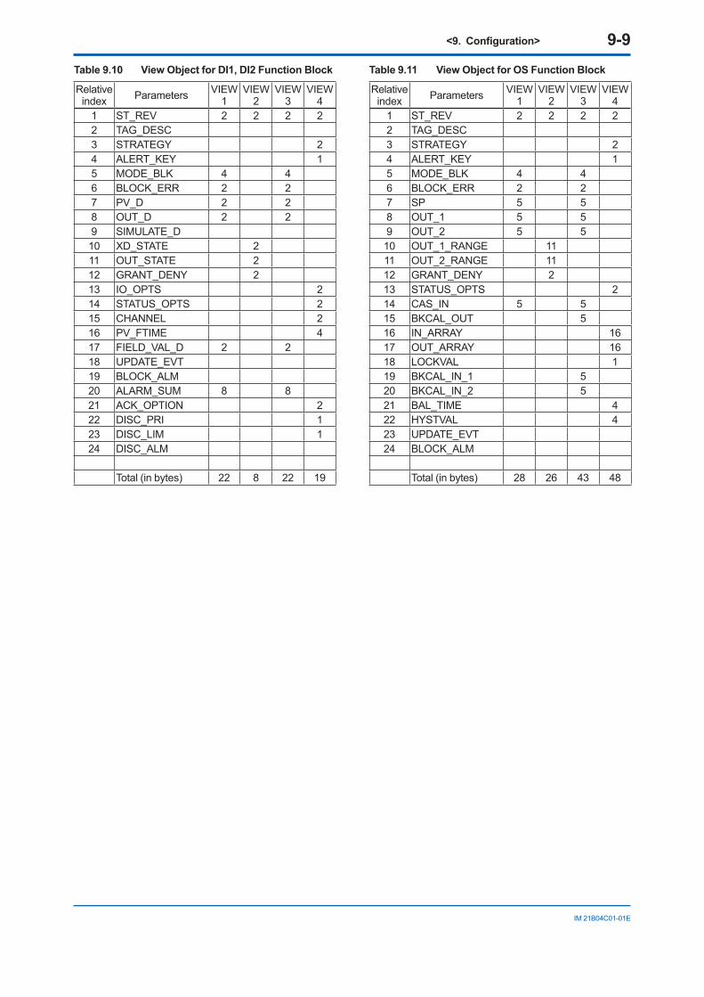
<9. Configuration> 9-9
IM 21B04C01-01E
Table 9.10 View Object for DI1, DI2 Function Block
Relative index Parameters VIEW
1VIEW
2VIEW
3VIEW
41 ST_REV 2 2 2 22 TAG_DESC3 STRATEGY 24 ALERT_KEY 15 MODE_BLK 4 46 BLOCK_ERR 2 27 PV_D 2 28 OUT_D 2 29 SIMULATE_D10 XD_STATE 211 OUT_STATE 212 GRANT_DENY 213 IO_OPTS 214 STATUS_OPTS 215 CHANNEL 216 PV_FTIME 417 FIELD_VAL_D 2 218 UPDATE_EVT19 BLOCK_ALM20 ALARM_SUM 8 821 ACK_OPTION 222 DISC_PRI 123 DISC_LIM 124 DISC_ALM
Total (in bytes) 22 8 22 19
Table 9.11 View Object for OS Function Block
Relative index Parameters VIEW
1VIEW
2VIEW
3VIEW
41 ST_REV 2 2 2 22 TAG_DESC3 STRATEGY 24 ALERT_KEY 15 MODE_BLK 4 46 BLOCK_ERR 2 27 SP 5 58 OUT_1 5 59 OUT_2 5 510 OUT_1_RANGE 1111 OUT_2_RANGE 1112 GRANT_DENY 213 STATUS_OPTS 214 CAS_IN 5 515 BKCAL_OUT 516 IN_ARRAY 1617 OUT_ARRAY 1618 LOCKVAL 119 BKCAL_IN_1 520 BKCAL_IN_2 521 BAL_TIME 422 HYSTVAL 423 UPDATE_EVT24 BLOCK_ALM
Total (in bytes) 28 26 43 48
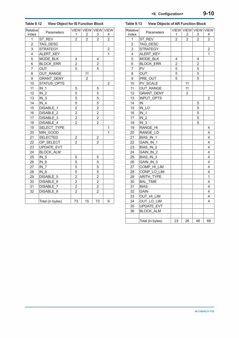
<9. Configuration> 9-10
IM 21B04C01-01E
Table 9.12 View Object for IS Function Block
Relative index Parameters VIEW
1VIEW
2VIEW
3VIEW
41 ST_REV 2 2 2 22 TAG_DESC3 STRATEGY 24 ALERT_KEY 15 MODE_BLK 4 46 BLOCK_ERR 2 27 OUT 5 58 OUT_RANGE 119 GRANT_DENY 210 STATUS_OPTS 211 IN_1 5 512 IN_2 5 513 IN_3 5 514 IN_4 5 515 DISABLE_1 2 216 DISABLE_2 2 217 DISABLE_3 2 218 DISABLE_4 2 219 SELECT_TYPE 120 MIN_GOOD 121 SELECTED 2 222 OP_SELECT 2 223 UPDATE_EVT24 BLOCK_ALM25 IN_5 5 526 IN_6 5 527 IN_7 5 528 IN_8 5 529 DISABLE_5 2 230 DISABLE_6 2 231 DISABLE_7 2 232 DISABLE_8 2 2
Total (in bytes) 73 15 73 9
Table 9.13 View Objects of AR Function Block
Relative index Parameters VIEW
1VIEW
2VIEW
3VIEW
41 ST_REV 2 2 2 22 TAG_DESC3 STRATEGY 24 ALERT_KEY 15 MODE_BLK 4 46 BLOCK_ERR 2 27 PV 5 58 OUT 5 59 PRE_OUT 5 510 PV_SCALE 1111 OUT_RANGE 1112 GRANT_DENY 213 INPUT_OPTS 214 IN 515 IN_LO 516 IN_1 517 IN_2 518 IN_3 519 RANGE_HI 420 RANGE_LO 421 BIAS_IN_1 422 GAIN_IN_1 423 BIAS_IN_2 424 GAIN_IN_2 425 BIAS_IN_3 426 GAIN_IN_3 427 COMP_HI_LIM 428 CONP_LO_LIM 429 ARITH_TYPE 130 BAL_TIME 431 BIAS 432 GAIN 433 OUT_HI_LIM 434 OUT_LO_LIM 435 UPDATE_EVT36 BLOCK_ALM
Total (in bytes) 23 26 48 68
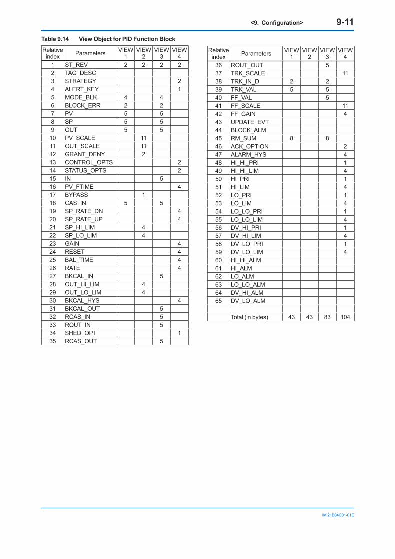
<9. Configuration> 9-11
IM 21B04C01-01E
Table 9.14 View Object for PID Function Block
Relative index Parameters VIEW
1VIEW
2VIEW
3VIEW
41 ST_REV 2 2 2 22 TAG_DESC3 STRATEGY 24 ALERT_KEY 15 MODE_BLK 4 46 BLOCK_ERR 2 27 PV 5 58 SP 5 59 OUT 5 510 PV_SCALE 1111 OUT_SCALE 1112 GRANT_DENY 213 CONTROL_OPTS 214 STATUS_OPTS 215 IN 516 PV_FTIME 417 BYPASS 118 CAS_IN 5 519 SP_RATE_DN 420 SP_RATE_UP 421 SP_HI_LIM 422 SP_LO_LIM 423 GAIN 424 RESET 425 BAL_TIME 426 RATE 427 BKCAL_IN 528 OUT_HI_LIM 429 OUT_LO_LIM 430 BKCAL_HYS 431 BKCAL_OUT 532 RCAS_IN 533 ROUT_IN 534 SHED_OPT 135 RCAS_OUT 5
Relative index Parameters VIEW
1VIEW
2VIEW
3VIEW
436 ROUT_OUT 537 TRK_SCALE 1138 TRK_IN_D 2 239 TRK_VAL 5 540 FF_VAL 541 FF_SCALE 1142 FF_GAIN 443 UPDATE_EVT44 BLOCK_ALM45 RM_SUM 8 846 ACK_OPTION 247 ALARM_HYS 448 HI_HI_PRI 149 HI_HI_LIM 450 HI_PRI 151 HI_LIM 452 LO_PRI 153 LO_LIM 454 LO_LO_PRI 155 LO_LO_LIM 456 DV_HI_PRI 157 DV_HI_LIM 458 DV_LO_PRI 159 DV_LO_LIM 460 HI_HI_ALM61 HI_ALM62 LO_ALM63 LO_LO_ALM64 DV_HI_ALM65 DV_LO_ALM
Total (in bytes) 43 43 83 104
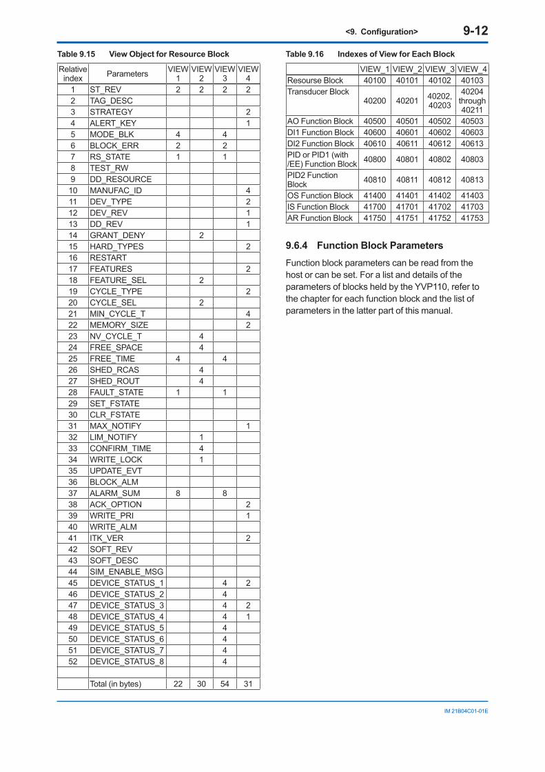
<9. Configuration> 9-12
IM 21B04C01-01E
Table 9.15 View Object for Resource Block
Relative index Parameters VIEW
1VIEW
2VIEW
3VIEW
41 ST_REV 2 2 2 22 TAG_DESC3 STRATEGY 24 ALERT_KEY 15 MODE_BLK 4 46 BLOCK_ERR 2 27 RS_STATE 1 18 TEST_RW9 DD_RESOURCE10 MANUFAC_ID 411 DEV_TYPE 212 DEV_REV 113 DD_REV 114 GRANT_DENY 215 HARD_TYPES 216 RESTART17 FEATURES 218 FEATURE_SEL 219 CYCLE_TYPE 220 CYCLE_SEL 221 MIN_CYCLE_T 422 MEMORY_SIZE 223 NV_CYCLE_T 424 FREE_SPACE 425 FREE_TIME 4 426 SHED_RCAS 427 SHED_ROUT 428 FAULT_STATE 1 129 SET_FSTATE30 CLR_FSTATE31 MAX_NOTIFY 132 LIM_NOTIFY 133 CONFIRM_TIME 434 WRITE_LOCK 135 UPDATE_EVT36 BLOCK_ALM37 ALARM_SUM 8 838 ACK_OPTION 239 WRITE_PRI 140 WRITE_ALM41 ITK_VER 242 SOFT_REV43 SOFT_DESC44 SIM_ENABLE_MSG45 DEVICE_STATUS_1 4 246 DEVICE_STATUS_2 447 DEVICE_STATUS_3 4 248 DEVICE_STATUS_4 4 149 DEVICE_STATUS_5 450 DEVICE_STATUS_6 451 DEVICE_STATUS_7 452 DEVICE_STATUS_8 4
Total (in bytes) 22 30 54 31
Table 9.16 Indexes of View for Each Block
VIEW_1 VIEW_2 VIEW_3 VIEW_4Resourse Block 40100 40101 40102 40103Transducer Block
40200 40201 40202,40203
40204 through 40211
AO Function Block 40500 40501 40502 40503DI1 Function Block 40600 40601 40602 40603DI2 Function Block 40610 40611 40612 40613PID or PID1 (with /EE) Function Block 40800 40801 40802 40803
PID2 Function Block 40810 40811 40812 40813
OS Function Block 41400 41401 41402 41403IS Function Block 41700 41701 41702 41703AR Function Block 41750 41751 41752 41753
9.6.4 Function Block ParametersFunction block parameters can be read from the host or can be set. For a list and details of the parameters of blocks held by the YVP110, refer to the chapter for each function block and the list of parameters in the latter part of this manual.
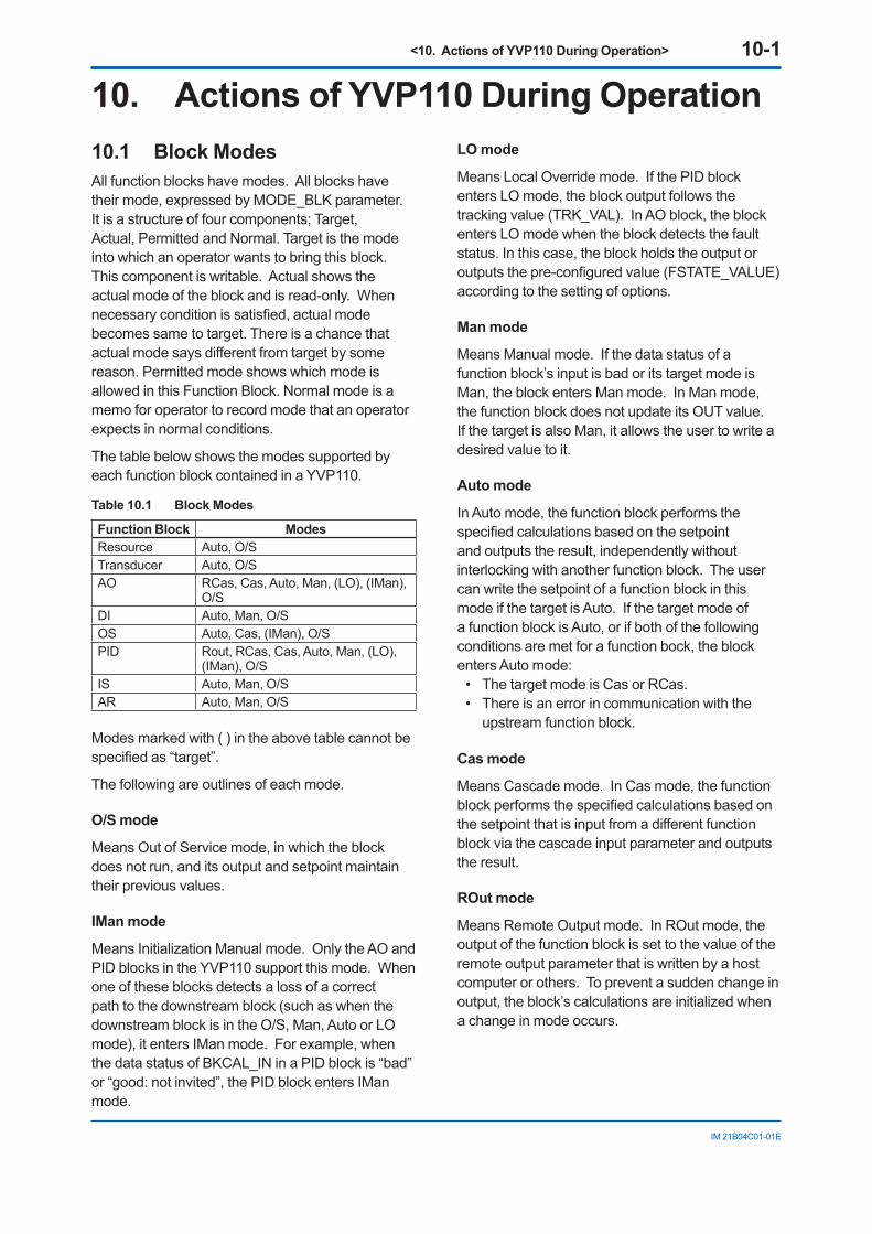
<10. Actions of YVP110 During Operation> 10-1
IM 21B04C01-01E
10. Actions of YVP110 During Operation10.1 Block ModesAll function blocks have modes. All blocks have their mode, expressed by MODE_BLK parameter. It is a structure of four components; Target, Actual, Permitted and Normal. Target is the mode into which an operator wants to bring this block. This component is writable. Actual shows the actual mode of the block and is read-only. When necessary condition is satisfied, actual mode becomes same to target. There is a chance that actual mode says different from target by some reason. Permitted mode shows which mode is allowed in this Function Block. Normal mode is a memo for operator to record mode that an operator expects in normal conditions.
The table below shows the modes supported by each function block contained in a YVP110.
Table 10.1 Block Modes
Function Block ModesResource Auto, O/STransducer Auto, O/SAO RCas, Cas, Auto, Man, (LO), (IMan),
O/SDI Auto, Man, O/SOS Auto, Cas, (IMan), O/SPID Rout, RCas, Cas, Auto, Man, (LO),
(IMan), O/SIS Auto, Man, O/SAR Auto, Man, O/S
Modes marked with ( ) in the above table cannot be specified as “target”.
The following are outlines of each mode.
O/S mode
Means Out of Service mode, in which the block does not run, and its output and setpoint maintain their previous values.
IMan mode
Means Initialization Manual mode. Only the AO and PID blocks in the YVP110 support this mode. When one of these blocks detects a loss of a correct path to the downstream block (such as when the downstream block is in the O/S, Man, Auto or LO mode), it enters IMan mode. For example, when the data status of BKCAL_IN in a PID block is “bad” or “good: not invited”, the PID block enters IMan mode.
LO mode
Means Local Override mode. If the PID block enters LO mode, the block output follows the tracking value (TRK_VAL). In AO block, the block enters LO mode when the block detects the fault status. In this case, the block holds the output or outputs the pre-configured value (FSTATE_VALUE) according to the setting of options.
Man mode
Means Manual mode. If the data status of a function block’s input is bad or its target mode is Man, the block enters Man mode. In Man mode, the function block does not update its OUT value. If the target is also Man, it allows the user to write a desired value to it.
Auto mode
In Auto mode, the function block performs the specified calculations based on the setpoint and outputs the result, independently without interlocking with another function block. The user can write the setpoint of a function block in this mode if the target is Auto. If the target mode of a function block is Auto, or if both of the following conditions are met for a function bock, the block enters Auto mode:
• The target mode is Cas or RCas. • There is an error in communication with the
upstream function block.
Cas mode
Means Cascade mode. In Cas mode, the function block performs the specified calculations based on the setpoint that is input from a different function block via the cascade input parameter and outputs the result.
ROut mode
Means Remote Output mode. In ROut mode, the output of the function block is set to the value of the remote output parameter that is written by a host computer or others. To prevent a sudden change in output, the block’s calculations are initialized when a change in mode occurs.
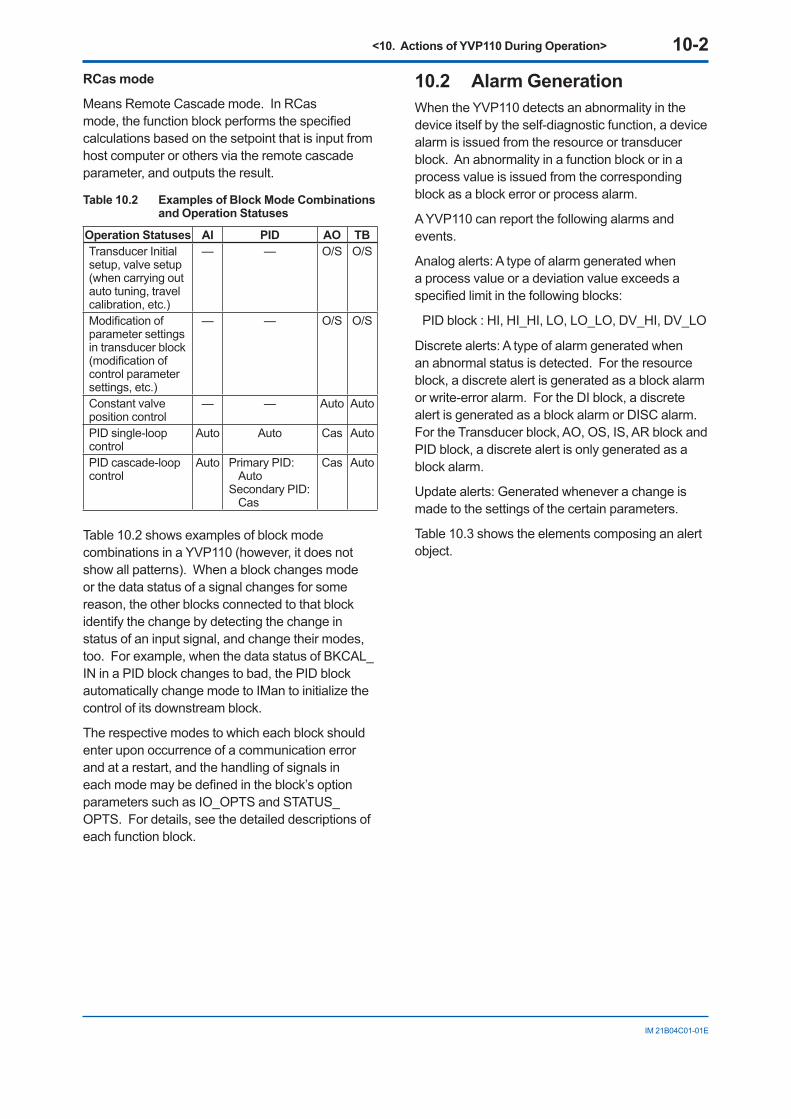
<10. Actions of YVP110 During Operation> 10-2
IM 21B04C01-01E
RCas mode
Means Remote Cascade mode. In RCas mode, the function block performs the specified calculations based on the setpoint that is input from host computer or others via the remote cascade parameter, and outputs the result.
Table 10.2 Examples of Block Mode Combinations and Operation Statuses
Operation Statuses AI PID AO TBTransducer Initial setup, valve setup (when carrying out auto tuning, travel calibration, etc.)
— — O/S O/S
Modification of parameter settings in transducer block (modification of control parameter settings, etc.)
— — O/S O/S
Constant valve position control
— — Auto Auto
PID single-loop control
Auto Auto Cas Auto
PID cascade-loop control
Auto Primary PID: Auto
Secondary PID: Cas
Cas Auto
Table 10.2 shows examples of block mode combinations in a YVP110 (however, it does not show all patterns). When a block changes mode or the data status of a signal changes for some reason, the other blocks connected to that block identify the change by detecting the change in status of an input signal, and change their modes, too. For example, when the data status of BKCAL_IN in a PID block changes to bad, the PID block automatically change mode to IMan to initialize the control of its downstream block.
The respective modes to which each block should enter upon occurrence of a communication error and at a restart, and the handling of signals in each mode may be defined in the block’s option parameters such as IO_OPTS and STATUS_OPTS. For details, see the detailed descriptions of each function block.
10.2 Alarm GenerationWhen the YVP110 detects an abnormality in the device itself by the self-diagnostic function, a device alarm is issued from the resource or transducer block. An abnormality in a function block or in a process value is issued from the corresponding block as a block error or process alarm.
A YVP110 can report the following alarms and events.
Analog alerts: A type of alarm generated when a process value or a deviation value exceeds a specified limit in the following blocks:
PID block : HI, HI_HI, LO, LO_LO, DV_HI, DV_LO
Discrete alerts: A type of alarm generated when an abnormal status is detected. For the resource block, a discrete alert is generated as a block alarm or write-error alarm. For the DI block, a discrete alert is generated as a block alarm or DISC alarm. For the Transducer block, AO, OS, IS, AR block and PID block, a discrete alert is only generated as a block alarm.
Update alerts: Generated whenever a change is made to the settings of the certain parameters.
Table 10.3 shows the elements composing an alert object.
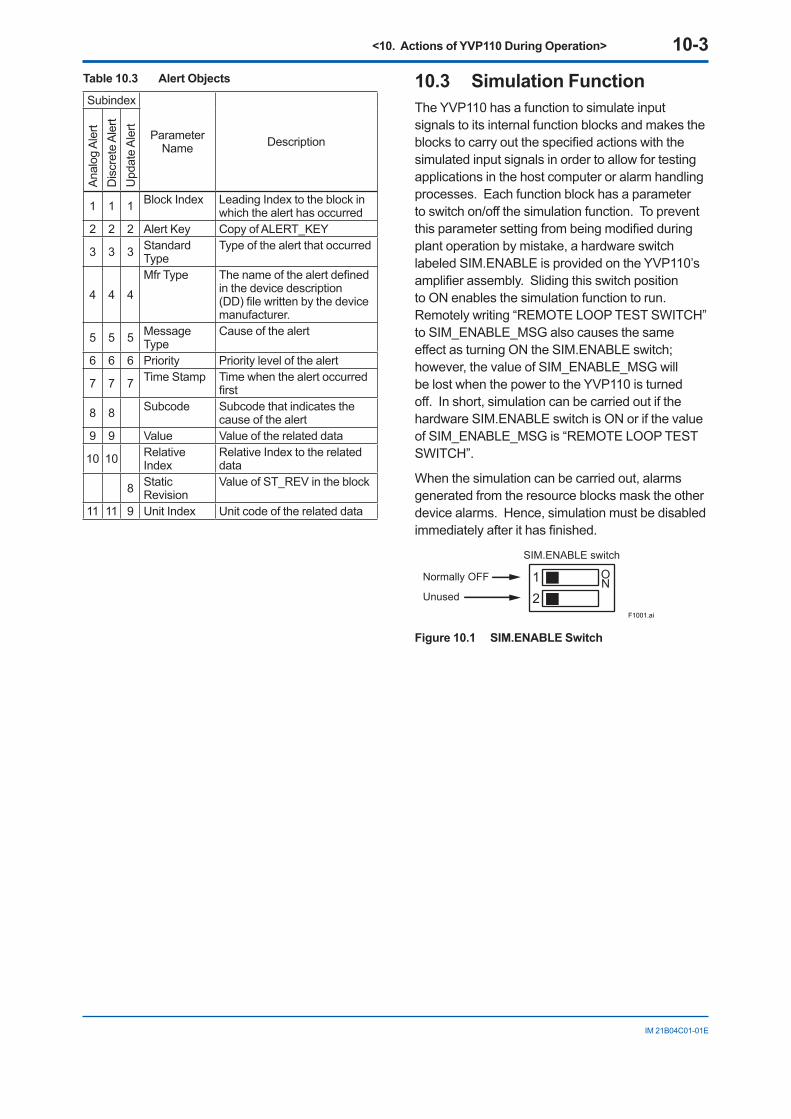
<10. Actions of YVP110 During Operation> 10-3
IM 21B04C01-01E
Table 10.3 Alert Objects
Subindex
Parameter Name Description
Anal
og A
lert
D
iscr
ete
Aler
tU
pdat
e Al
ert
1 1 1 Block Index Leading Index to the block in which the alert has occurred
2 2 2 Alert Key Copy of ALERT_KEY
3 3 3 Standard Type
Type of the alert that occurred
4 4 4
Mfr Type The name of the alert defined in the device description (DD) file written by the device manufacturer.
5 5 5 Message Type
Cause of the alert
6 6 6 Priority Priority level of the alert
7 7 7 Time Stamp Time when the alert occurred first
8 8 Subcode Subcode that indicates the cause of the alert
9 9 Value Value of the related data
10 10 Relative Index
Relative Index to the related data
8 Static Revision
Value of ST_REV in the block
11 11 9 Unit Index Unit code of the related data
10.3 Simulation FunctionThe YVP110 has a function to simulate input signals to its internal function blocks and makes the blocks to carry out the specified actions with the simulated input signals in order to allow for testing applications in the host computer or alarm handling processes. Each function block has a parameter to switch on/off the simulation function. To prevent this parameter setting from being modified during plant operation by mistake, a hardware switch labeled SIM.ENABLE is provided on the YVP110’s amplifier assembly. Sliding this switch position to ON enables the simulation function to run. Remotely writing “REMOTE LOOP TEST SWITCH” to SIM_ENABLE_MSG also causes the same effect as turning ON the SIM.ENABLE switch; however, the value of SIM_ENABLE_MSG will be lost when the power to the YVP110 is turned off. In short, simulation can be carried out if the hardware SIM.ENABLE switch is ON or if the value of SIM_ENABLE_MSG is “REMOTE LOOP TEST SWITCH”.
When the simulation can be carried out, alarms generated from the resource blocks mask the other device alarms. Hence, simulation must be disabled immediately after it has finished.
F1001.ai
12
ONNormally OFF
Unused
SIM.ENABLE switch
Figure 10.1 SIM.ENABLE Switch
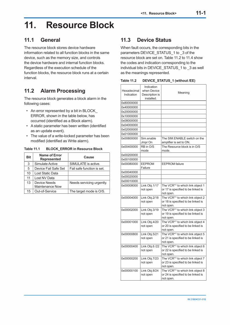
<11. Resource Block> 11-1
IM 21B04C01-01E
11. Resource Block 11.1 General The resource block stores device hardware information related to all function blocks in the same device, such as the memory size, and controls the device hardware and internal function blocks. Regardless of the execution schedule of the function blocks, the resource block runs at a certain interval.
11.2 Alarm Processing The resource block generates a block alarm in the following cases:
• An error represented by a bit in BLOCK_ERROR, shown in the table below, has occurred (identified as a Block alarm).
• A static parameter has been written (identified as an update event).
• The value of a write-locked parameter has been modified (identified as Write alarm).
Table 11.1 BLOCK_ERROR in Resource Block
Bit Name of Error Represented Cause
3 Simulate Active SIMULATE is active.5 Device Fail Safe Set Fail safe function is set.10 Lost Static Data11 Lost NV Data13 Device Needs
Maintenance NowNeeds servicing urgently.
15 Out-of-Service The target mode is O/S.
11.3 Device Status When fault occurs, the corresponding bits in the parameters DEVICE_STATUS_1 to _3 of the resource block are set on. Table 11.2 to 11.4 show the codes and indication corresponding to the individual bits in DEVICE_STATUS_1 to _3 as well as the meanings represented.
Table 11.2 DEVICE_STATUS_1 (without /EE)
Hexadecimal Indication
Indication when Device Description is
installed.
Meaning
0x800000000x400000000x200000000x100000000x080000000x040000000x020000000x010000000x00800000 Sim.enable
Jmpr OnThe SIM.ENABLE switch on the amplifier is set to ON.
0x00400000 RB in O/S mode
The Resource block is in O/S mode.
0x002000000x001000000x00080000 EEPROM
FailureEEPROM failure
0x000400000x000200000x000100000x00008000 Link Obj.1/17
not openThe VCR*1 to which link object 1 or 17 is specified to be linked is not open.
0x00004000 Link Obj.2/18not open
The VCR*1 to which link object 2 or 18 is specified to be linked is not open.
0x00002000 Link Obj.3/19not open
The VCR*1 to which link object 3 or 19 is specified to be linked is not open.
0x00001000 Link Obj.4/20not open
The VCR*1 to which link object 4 or 20 is specified to be linked is not open.
0x00000800 Link Obj.5/21not open
The VCR*1 to which link object 5 or 21 is specified to be linked is not open.
0x00000400 Link Obj.6 /22not open
The VCR*1 to which link object 6 or 22 is specified to be linked is not open.
0x00000200 Link Obj.7/23not open
The VCR*1 to which link object 7 or 23 is specified to be linked is not open.
0x00000100 Link Obj.8/24not open
The VCR*1 to which link object 8 or 24 is specified to be linked is not open.
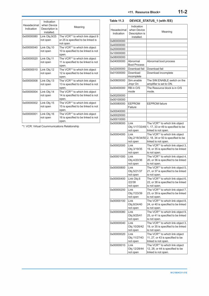
<11. Resource Block> 11-2
IM 21B04C01-01E
Hexadecimal Indication
Indication when Device Description is
installed.
Meaning
0x00000080 Link Obj.9/25not open
The VCR*1 to which link object 9 or 25 is specified to be linked is not open.
0x00000040 Link Obj.10not open
The VCR*1 to which link object 10 is specified to be linked is not open.
0x00000020 Link Obj.11not open
The VCR*1 to which link object 11 is specified to be linked is not open.
0x00000010 Link Obj.12not open
The VCR*1 to which link object 12 is specified to be linked is not open.
0x00000008 Link Obj.13not open
The VCR*1 to which link object 13 is specified to be linked is not open.
0x00000004 Link Obj.14not open
The VCR*1 to which link object 14 is specified to be linked is not open.
0x00000002 Link Obj.15not open
The VCR*1 to which link object 15 is specified to be linked is not open.
0x00000001 Link Obj.16not open
The VCR*1 to which link object 16 is specified to be linked is not open.
*1: VCR: Virtual Coummunications Relationship
Table 11.3 DEVICE_STATUS_1 (with /EE)
Hexadecimal Indication
Indication when Device Description is
installed.
Meaning
0x800000000x400000000x200000000x100000000x080000000x04000000 Abnormal
Boot ProcessAbnormal boot process
0x02000000 Download fail Download fail0x01000000 Download
incompleteDownload incomplete
0x00800000 Sim.enable Jmpr On
The SIM.ENABLE switch on the amplifier is set to ON.
0x00400000 RB in O/S mode
The Resource block is in O/S mode.
0x002000000x001000000x00080000 EEPROM
FailureEEPROM failure
0x000400000x000200000x000100000x00008000 Link
Obj.1/17/33/49not open
The VCR*1 to which link object 1, 17, 33 or 49 is specified to be linked is not open.
0x00004000 Link Obj.2/18/34/50not open
The VCR*1 to which link object 2, 18, 34 or 50 is specified to be linked is not open.
0x00002000 Link Obj.3/19/35not open
The VCR*1 to which link object 3, 19, or 35 is specified to be linked is not open.
0x00001000 Link Obj.4/20/36not open
The VCR*1 to which link object 4, 20, or 36 is specified to be linked is not open.
0x00000800 Link Obj.5/21/37not open
The VCR*1 to which link object 5, 21, or 37 is specified to be linked is not open.
0x00000400 Link Obj.6 /22/38not open
The VCR*1 to which link object 6, 22, or 38 is specified to be linked is not open.
0x00000200 Link Obj.7/23/39not open
The VCR*1 to which link object 7, 23, or 39 is specified to be linked is not open.
0x00000100 Link Obj.8/24/40not open
The VCR*1 to which link object 8, 24, or 40 is specified to be linked is not open.
0x00000080 Link Obj.9/25/41not open
The VCR*1 to which link object 9, 25, or 41 is specified to be linked is not open.
0x00000040 Link Obj.10/26/42not open
The VCR*1 to which link object 3, 19, or 35 is specified to be linked is not open.
0x00000020 Link Obj.11/27/43not open
The VCR*1 to which link object 11, 27, or 43 is specified to be linked is not open.
0x00000010 Link Obj.12/28/44not open
The VCR*1 to which link object 12, 28, or 44 is specified to be linked is not open.
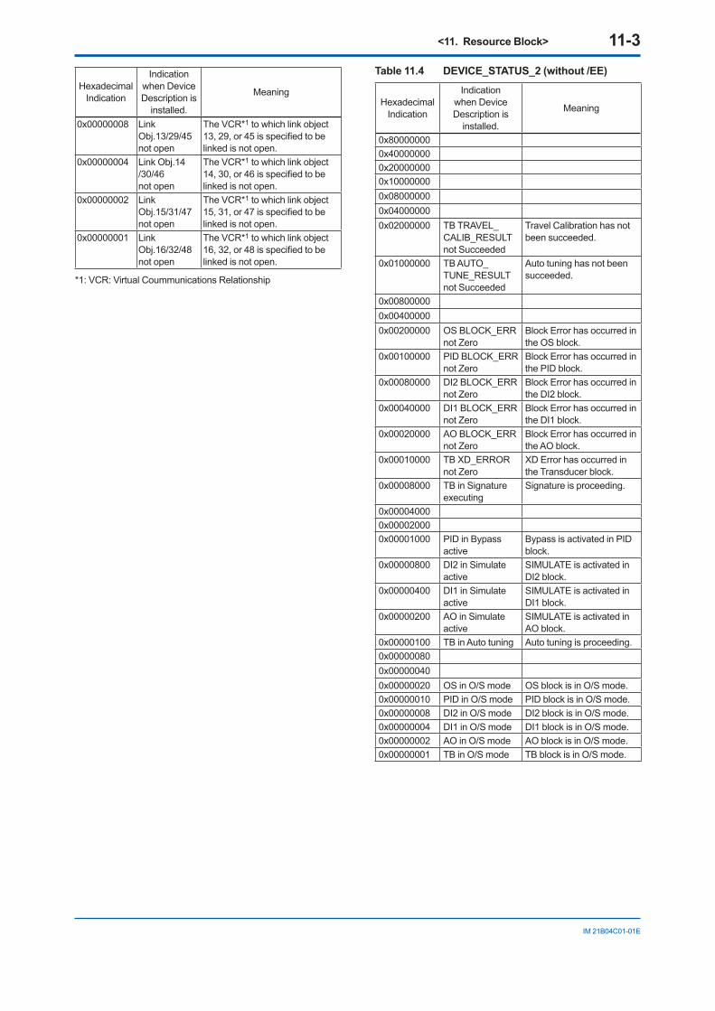
<11. Resource Block> 11-3
IM 21B04C01-01E
Hexadecimal Indication
Indication when Device Description is
installed.
Meaning
0x00000008 Link Obj.13/29/45not open
The VCR*1 to which link object 13, 29, or 45 is specified to be linked is not open.
0x00000004 Link Obj.14 /30/46not open
The VCR*1 to which link object 14, 30, or 46 is specified to be linked is not open.
0x00000002 Link Obj.15/31/47not open
The VCR*1 to which link object 15, 31, or 47 is specified to be linked is not open.
0x00000001 Link Obj.16/32/48not open
The VCR*1 to which link object 16, 32, or 48 is specified to be linked is not open.
*1: VCR: Virtual Coummunications Relationship
Table 11.4 DEVICE_STATUS_2 (without /EE)
Hexadecimal Indication
Indication when Device Description is
installed.
Meaning
0x800000000x400000000x200000000x100000000x080000000x040000000x02000000 TB TRAVEL_
CALIB_RESULT not Succeeded
Travel Calibration has not been succeeded.
0x01000000 TB AUTO_TUNE_RESULT not Succeeded
Auto tuning has not been succeeded.
0x008000000x004000000x00200000 OS BLOCK_ERR
not ZeroBlock Error has occurred in the OS block.
0x00100000 PID BLOCK_ERR not Zero
Block Error has occurred in the PID block.
0x00080000 DI2 BLOCK_ERR not Zero
Block Error has occurred in the DI2 block.
0x00040000 DI1 BLOCK_ERR not Zero
Block Error has occurred in the DI1 block.
0x00020000 AO BLOCK_ERR not Zero
Block Error has occurred in the AO block.
0x00010000 TB XD_ERROR not Zero
XD Error has occurred in the Transducer block.
0x00008000 TB in Signature executing
Signature is proceeding.
0x000040000x000020000x00001000 PID in Bypass
activeBypass is activated in PID block.
0x00000800 DI2 in Simulate active
SIMULATE is activated in DI2 block.
0x00000400 DI1 in Simulate active
SIMULATE is activated in DI1 block.
0x00000200 AO in Simulate active
SIMULATE is activated in AO block.
0x00000100 TB in Auto tuning Auto tuning is proceeding.0x000000800x000000400x00000020 OS in O/S mode OS block is in O/S mode.0x00000010 PID in O/S mode PID block is in O/S mode.0x00000008 DI2 in O/S mode DI2 block is in O/S mode.0x00000004 DI1 in O/S mode DI1 block is in O/S mode.0x00000002 AO in O/S mode AO block is in O/S mode.0x00000001 TB in O/S mode TB block is in O/S mode.
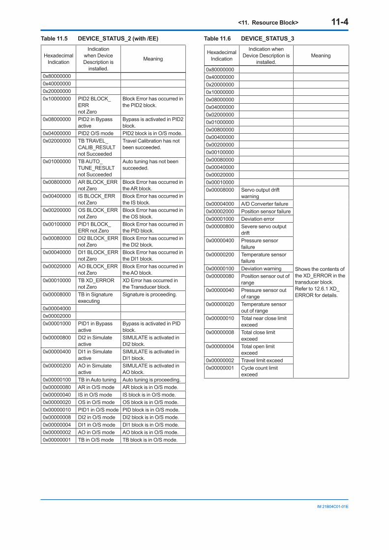
<11. Resource Block> 11-4
IM 21B04C01-01E
Table 11.5 DEVICE_STATUS_2 (with /EE)
Hexadecimal Indication
Indication when Device Description is
installed.
Meaning
0x800000000x400000000x200000000x10000000 PID2 BLOCK_
ERRnot Zero
Block Error has occurred in the PID2 block.
0x08000000 PID2 in Bypassactive
Bypass is activated in PID2 block.
0x04000000 PID2 O/S mode PID2 block is in O/S mode.0x02000000 TB TRAVEL_
CALIB_RESULT not Succeeded
Travel Calibration has not been succeeded.
0x01000000 TB AUTO_TUNE_RESULT not Succeeded
Auto tuning has not been succeeded.
0x00800000 AR BLOCK_ERRnot Zero
Block Error has occurred in the AR block.
0x00400000 IS BLOCK_ERRnot Zero
Block Error has occurred in the IS block.
0x00200000 OS BLOCK_ERR not Zero
Block Error has occurred in the OS block.
0x00100000 PID1 BLOCK_ERR not Zero
Block Error has occurred in the PID block.
0x00080000 DI2 BLOCK_ERR not Zero
Block Error has occurred in the DI2 block.
0x00040000 DI1 BLOCK_ERR not Zero
Block Error has occurred in the DI1 block.
0x00020000 AO BLOCK_ERR not Zero
Block Error has occurred in the AO block.
0x00010000 TB XD_ERROR not Zero
XD Error has occurred in the Transducer block.
0x00008000 TB in Signature executing
Signature is proceeding.
0x000040000x000020000x00001000 PID1 in Bypass
activeBypass is activated in PID block.
0x00000800 DI2 in Simulate active
SIMULATE is activated in DI2 block.
0x00000400 DI1 in Simulate active
SIMULATE is activated in DI1 block.
0x00000200 AO in Simulate active
SIMULATE is activated in AO block.
0x00000100 TB in Auto tuning Auto tuning is proceeding.0x00000080 AR in O/S mode AR block is in O/S mode.0x00000040 IS in O/S mode IS block is in O/S mode.0x00000020 OS in O/S mode OS block is in O/S mode.0x00000010 PID1 in O/S mode PID block is in O/S mode.0x00000008 DI2 in O/S mode DI2 block is in O/S mode.0x00000004 DI1 in O/S mode DI1 block is in O/S mode.0x00000002 AO in O/S mode AO block is in O/S mode.0x00000001 TB in O/S mode TB block is in O/S mode.
Table 11.6 DEVICE_STATUS_3
Hexadecimal Indication
Indication when Device Description is
installed.Meaning
0x800000000x400000000x200000000x100000000x080000000x040000000x020000000x010000000x008000000x004000000x002000000x001000000x000800000x000400000x000200000x000100000x00008000 Servo output drift
warning
Shows the contents of the XD_ERROR in the transducer block. Refer to 12.6.1 XD_ERROR for details.
0x00004000 A/D Converter failure0x00002000 Position sensor failure0x00001000 Deviation error0x00000800 Severe servo output
drift0x00000400 Pressure sensor
failure0x00000200 Temperature sensor
failure0x00000100 Deviation warning0x00000080 Position sensor out of
range0x00000040 Pressure sensor out
of range0x00000020 Temperature sensor
out of range0x00000010 Total near close limit
exceed0x00000008 Total close limit
exceed0x00000004 Total open limit
exceed0x00000002 Travel limit exceed0x00000001 Cycle count limit
exceed
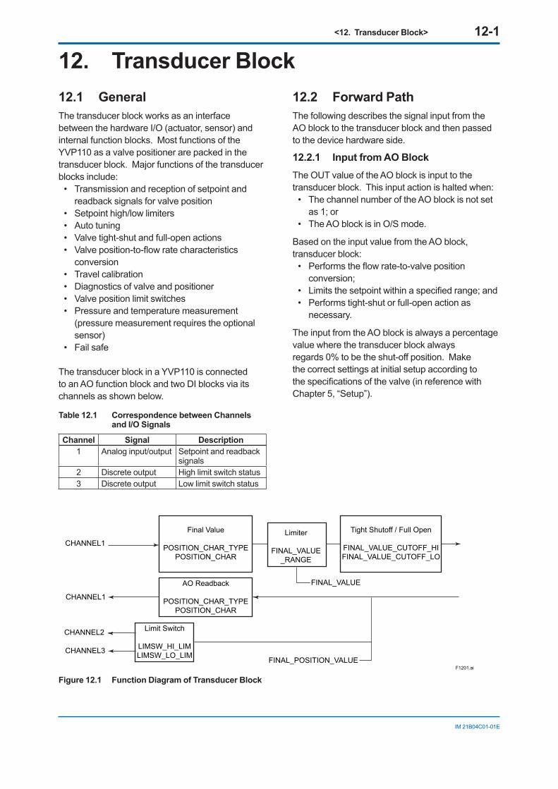
<12. Transducer Block> 12-1
IM 21B04C01-01E
12. Transducer Block12.1 GeneralThe transducer block works as an interface between the hardware I/O (actuator, sensor) and internal function blocks. Most functions of the YVP110 as a valve positioner are packed in the transducer block. Major functions of the transducer blocks include:
• Transmission and reception of setpoint and readback signals for valve position
• Setpoint high/low limiters• Auto tuning• Valve tight-shut and full-open actions• Valve position-to-flow rate characteristics
conversion• Travel calibration• Diagnostics of valve and positioner• Valve position limit switches• Pressure and temperature measurement
(pressure measurement requires the optional sensor)
• Fail safe
The transducer block in a YVP110 is connected to an AO function block and two DI blocks via its channels as shown below.
Table 12.1 Correspondence between Channels and I/O Signals
Channel Signal Description1 Analog input/output Setpoint and readback
signals2 Discrete output High limit switch status3 Discrete output Low limit switch status
12.2 Forward PathThe following describes the signal input from the AO block to the transducer block and then passed to the device hardware side.
12.2.1 Input from AO BlockThe OUT value of the AO block is input to the transducer block. This input action is halted when:
• The channel number of the AO block is not set as 1; or
• The AO block is in O/S mode.
Based on the input value from the AO block, transducer block:
• Performs the flow rate-to-valve position conversion;
• Limits the setpoint within a specified range; and • Performs tight-shut or full-open action as
necessary.
The input from the AO block is always a percentage value where the transducer block always regards 0% to be the shut-off position. Make the correct settings at initial setup according to the specifications of the valve (in reference with Chapter 5, “Setup”).
F1201.ai
CHANNEL1
FINAL_VALUE
Final Value
POSITION_CHAR_TYPEPOSITION_CHAR
CHANNEL1
FINAL_POSITION_VALUE
AO Readback
POSITION_CHAR_TYPEPOSITION_CHAR
CHANNEL3
CHANNEL2 Limit Switch
LIMSW_HI_LIMLIMSW_LO_LIM
Limiter
FINAL_VALUE_RANGE
Tight Shutoff / Full Open
FINAL_VALUE_CUTOFF_HIFINAL_VALUE_CUTOFF_LO
Figure 12.1 Function Diagram of Transducer Block
<12. Transducer Block> 12-2
IM 21B04C01-01E
12.2.2 Position-to-flow Rate Characteristic Conversion
The parameter POSITION_CHAR_TYPE defines the characteristics between the valve position and flow rate, and can be set to one the following: 1 = linear 2 = equal percent (50:1) 3 = equal percent (30:1) 4 = quick open (reversal of equal percent 50:1) 5 = Camflex Percen tage 255 = user-defined
Writing the value 255 allows you to define the desired characteristics by 10 line segments for evenly divided input levels. The coordinates (0,0) and (100,100) are fixed; set the values corresponding to OUT(Output of AO block) = 10%, 20%, 30%..., 80%, 90%. Note that a set value must be greater than the preceding set value; the output must increase as the input increases.
This flow rate conversion is applied to the signal in the backword path as well.
12.2.3 FINAL_VALUE and RangeThe parameter FINAL_VALUE contains the valve position setpoint for valve control, and its value is always a percent value where 0% is the shut-off position as is the case for the input signal. High and low limits for the value of FINAL_VALUE.value can be set in FINAL_VALUE_RANGE.
12.2.4 Tight-shut and Full-open ActionsThe tight-shut action is an action to decrease the output pressure to a level much lower than the 0% pressure level for an air-to-open valve (or increase it to a level much higher than the 0% pressure level for an air-to-close valve) when FINAL_VALUE.value is less than FINAL_VALUE_CUTOFF_LO in order to ensure that the valve is tightly shut off. After the tight-shut action is activated, when FINAL_VALUE.value becomes greater than FINAL_VALUE_CUTOFF_LO by 1% or more, the tight-shut action will turn off.
Conversely, the full-open action is an action to increase the output pressure to a level much higher than the 100% pressure level for an air-to-open valve (or decrease it to a level much lower than the 100% pressure level for an air-to-close valve) when FINAL_VALUE.value is larger than FINAL_VALUE_CUTOFF_HI in order to ensure that the valve is fully open. After the full-open action is activated, when FINAL_VALUE.value becomes less than FINAL_
VALUE_CUTOFF_HI by 1% or more, the full-open action will turn off.
Although the actual output signal level is changed to a level outside the range during the period when the tight-shut or full-open action is on, the value of FINAL_VALUE.value remains as computed and is not affected by these actions.
12.3 Backward PathThe following describes the signal input from the device hardware to the transducer block and then passed to other function blocks.
12.3.1 FINAL_POSITION_VALUEThe parameter FINAL_POSITION_VALUE contains a percentage value of the valve position sent from the position sensor where 0% is the shut-off position as is the case for FINAL_VALUE.value. When one or more of the following conditions become true, the data status of FINAL_POSITION_VALUE becomes Bad, which is notified to the connected AO block and upstream function blocks:
• Bad - Out of service: The block is in the O/S mode.
• Bad - Sensor failure: The position sensor has failed.
• Bad - Device failure: The A/D converter has failed.
• Bad - Non specific: The deviation exceeds the limit.
12.3.2 Limit SwitchesLimit switches monitor whether the valve position has reached a specified high or low limit position and send the high limit switch status to channel 2 and the low limit switch status to channel 3. The thresholds (settings) for the high and low limit switches should be set in LIMSW_HI_LIM and LIMSW_LO_LIM. The switch statuses sent to channels 2 and 3 mean: 0 = off (inactive) 1 = on (active)
Hysteresis of 1% is applied for both High and Low limit switch. While the limit switch of high side stays ON, it turns to OFF again only when the value of FINAL_POSITION_VALUE becomes smaller by 1% or less than the value of LIMSW_HI_LIM. Also, while limit switch of low side stays ON, it turns to OFF again only when the value of FINAL_POSITION_VALUE becomes greater by 1 % or more than the value of LIMSW_LO_LIM.
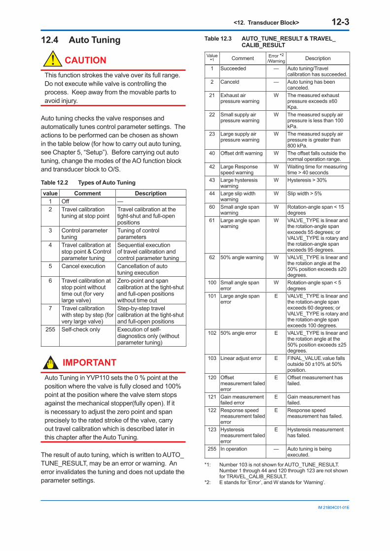
<12. Transducer Block> 12-3
IM 21B04C01-01E
12.4 Auto Tuning
CAUTIONThis function strokes the valve over its full range. Do not execute while valve is controlling the process. Keep away from the movable parts to avoid injury.
Auto tuning checks the valve responses and automatically tunes control parameter settings. The actions to be performed can be chosen as shown in the table below (for how to carry out auto tuning, see Chapter 5, “Setup”). Before carrying out auto tuning, change the modes of the AO function block and transducer block to O/S.
Table 12.2 Types of Auto Tuning
value Comment Description1 Off —2 Travel calibration
tuning at stop pointTravel calibration at the tight-shut and full-open positions
3 Control parameter tuning
Tuning of control parameters
4 Travel calibration at stop point & Control parameter tuning
Sequential execution of travel calibration and control parameter tuning
5 Cancel execution Cancellation of auto tuning execution
6 Travel calibration at stop point without time out (for very large valve)
Zero-point and span calibration at the tight-shut and full-open positions without time out
7 Travel calibration with step by step (for very large valve)
Step-by-step travel calibration at the tight-shut and full-open positions
255 Self-check only Execution of self-diagnostics only (without parameter tuning)
IMPORTANTAuto Tuning in YVP110 sets the 0 % point at the position where the valve is fully closed and 100% point at the position where the valve stem stops against the mechanical stopper(fully open). If it is necessary to adjust the zero point and span precisely to the rated stroke of the valve, carry out travel calibration which is described later in this chapter after the Auto Tuning.
The result of auto tuning, which is written to AUTO_TUNE_RESULT, may be an error or warning. An error invalidates the tuning and does not update the parameter settings.
Table 12.3 AUTO_TUNE_RESULT & TRAVEL_CALIB_RESULT
Value *1 Comment Error *2
/Warning Description
1 Succeeded — Auto tuning/Travel calibration has succeeded.
2 Canceld — Auto tuning has been canceled.
21 Exhaust air pressure warning
W The measured exhaust pressure exceeds ±60 Kpa.
22 Small supply air pressure warning
W The measured supply air pressure is less than 100 kPa.
23 Large supply air pressure warning
W The measured supply air pressure is greater than 800 kPa.
40 Offset drift warning W The offset falls outside the normal operation range.
42 Large Response speed warning
W Waiting time for measuring time > 40 seconds
43 Large hysteresis warning
W Hysteresis > 30%
44 Large slip width warning
W Slip width > 5%
60 Small angle span warning
W Rotation-angle span < 15 degrees
61 Large angle span warning
W VALVE_TYPE is linear and the rotation-angle span exceeds 55 degrees; or VALVE_TYPE is rotary and the rotation-angle span exceeds 95 degrees.
62 50% angle warning W VALVE_TYPE is linear and the rotation angle at the 50% position exceeds ±20 degrees.
100 Small angle span error
W Rotation-angle span < 5 degrees
101 Large angle span error
E VALVE_TYPE is linear and the rotation-angle span exceeds 60 degrees; or VALVE_TYPE is rotary and the rotation-angle span exceeds 100 degrees.
102 50% angle error E VALVE_TYPE is linear and the rotation angle at the 50% position exceeds ±25 degrees.
103 Linear adjust error E FINAL_VALUE.value falls outside 50 ±10% at 50% position.
120 Offset measurement failed error
E Offset measurement has failed.
121 Gain measurement failed error
E Gain measurement has failed.
122 Response speed measurement failed error
E Response speed measurement has failed.
123 Hysteresis measurement failed error
E Hysteresis measurement has failed.
255 In operation — Auto tuning is being executed.
*1: Number 103 is not shown for AUTO_TUNE_RESULT. Number 1 through 44 and 120 through 123 are not shown for TRAVEL_CALIB_RESULT.
*2: E stands for ‘Error’, and W stands for ‘Warning’.
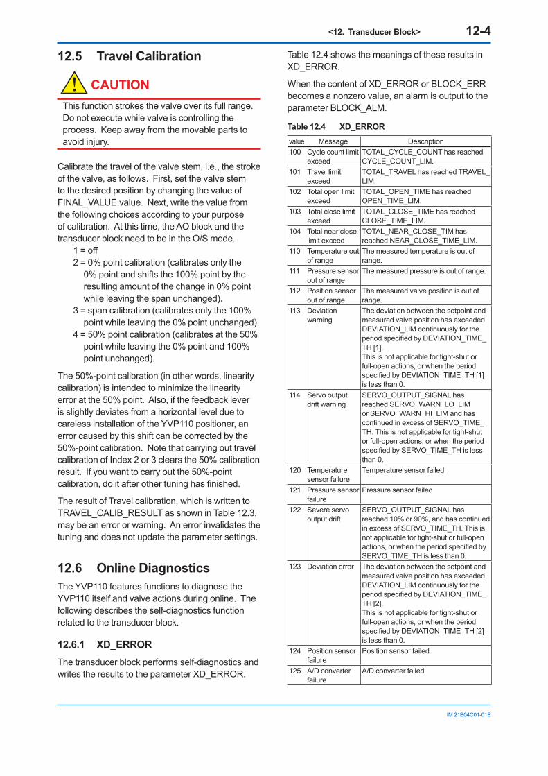
<12. Transducer Block> 12-4
IM 21B04C01-01E
12.5 Travel Calibration
CAUTIONThis function strokes the valve over its full range. Do not execute while valve is controlling the process. Keep away from the movable parts to avoid injury.
Calibrate the travel of the valve stem, i.e., the stroke of the valve, as follows. First, set the valve stem to the desired position by changing the value of FINAL_VALUE.value. Next, write the value from the following choices according to your purpose of calibration. At this time, the AO block and the transducer block need to be in the O/S mode.
1 = off2 = 0% point calibration (calibrates only the
0% point and shifts the 100% point by the resulting amount of the change in 0% point while leaving the span unchanged).
3 = span calibration (calibrates only the 100% point while leaving the 0% point unchanged).
4 = 50% point calibration (calibrates at the 50% point while leaving the 0% point and 100% point unchanged).
The 50%-point calibration (in other words, linearity calibration) is intended to minimize the linearity error at the 50% point. Also, if the feedback lever is slightly deviates from a horizontal level due to careless installation of the YVP110 positioner, an error caused by this shift can be corrected by the 50%-point calibration. Note that carrying out travel calibration of Index 2 or 3 clears the 50% calibration result. If you want to carry out the 50%-point calibration, do it after other tuning has finished.
The result of Travel calibration, which is written to TRAVEL_CALIB_RESULT as shown in Table 12.3, may be an error or warning. An error invalidates the tuning and does not update the parameter settings.
12.6 Online DiagnosticsThe YVP110 features functions to diagnose the YVP110 itself and valve actions during online. The following describes the self-diagnostics function related to the transducer block.
12.6.1 XD_ERRORThe transducer block performs self-diagnostics and writes the results to the parameter XD_ERROR.
Table 12.4 shows the meanings of these results in XD_ERROR.
When the content of XD_ERROR or BLOCK_ERR becomes a nonzero value, an alarm is output to the parameter BLOCK_ALM.
Table 12.4 XD_ERROR
value Message Description100 Cycle count limit
exceedTOTAL_CYCLE_COUNT has reached CYCLE_COUNT_LIM.
101 Travel limit exceed
TOTAL_TRAVEL has reached TRAVEL_LIM.
102 Total open limit exceed
TOTAL_OPEN_TIME has reached OPEN_TIME_LIM.
103 Total close limit exceed
TOTAL_CLOSE_TIME has reached CLOSE_TIME_LIM.
104 Total near close limit exceed
TOTAL_NEAR_CLOSE_TIM has reached NEAR_CLOSE_TIME_LIM.
110 Temperature out of range
The measured temperature is out of range.
111 Pressure sensor out of range
The measured pressure is out of range.
112 Position sensor out of range
The measured valve position is out of range.
113 Deviation warning
The deviation between the setpoint and measured valve position has exceeded DEVIATION_LIM continuously for the period specified by DEVIATION_TIME_TH [1].This is not applicable for tight-shut or full-open actions, or when the period specified by DEVIATION_TIME_TH [1] is less than 0.
114 Servo output drift warning
SERVO_OUTPUT_SIGNAL has reached SERVO_WARN_LO_LIM or SERVO_WARN_HI_LIM and has continued in excess of SERVO_TIME_TH. This is not applicable for tight-shut or full-open actions, or when the period specified by SERVO_TIME_TH is less than 0.
120 Temperature sensor failure
Temperature sensor failed
121 Pressure sensor failure
Pressure sensor failed
122 Severe servo output drift
SERVO_OUTPUT_SIGNAL has reached 10% or 90%, and has continued in excess of SERVO_TIME_TH. This is not applicable for tight-shut or full-open actions, or when the period specified by SERVO_TIME_TH is less than 0.
123 Deviation error The deviation between the setpoint and measured valve position has exceeded DEVIATION_LIM continuously for the period specified by DEVIATION_TIME_TH [2].This is not applicable for tight-shut or full-open actions, or when the period specified by DEVIATION_TIME_TH [2] is less than 0.
124 Position sensor failure
Position sensor failed
125 A/D converter failure
A/D converter failed
<12. Transducer Block> 12-5
IM 21B04C01-01E
12.6.2 Fail-safe ActionIf the “A/D converter failure,” “position sensor failure,” or “deviation error” event occurs in the XD_ERROR described above, the transducer block activates the specified fail-safe action by cutting the current signal to I/P module to zero. In addition, in the event of “position sensor failure” or “deviation error,” the fail-safe action will not be deactivated even when the cause of the failure/error is cleared. Writing “Clear non-latch” to the parameter RELEASE_FAILSAFE will finally deactivate the fail-safe action in this case. The fail-safe action activated in the event of “A/D converter failure” will be deactivated automatically when the cause of the failure is cleared.
12.6.3 Operation Result Integration The YVP110 has a function to integrate the following operation result quantities individually. To reset an integrated quantity, write 0 to the corresponding parameter.
• TOTAL_CYCLE_COUNT:
Incremented by 1 at each change in the direction of the valve action and indicates the total number of times of changes in direction of valve actions.
• TOTAL_TRAVEL:
Total travel distance of the stem position shown as a percentage of the valve position span.
• TOTAL_OPEN_TIME and TOTAL_CLOSE_TIME:
TOTAL_CLOSE_TIME contains the integrated time periods (in hours) when the valve position is equal to or less than the thresholds previously set in OPEN_CLOSE_THRESHOLD. TOTAL_OPEN_TIME is the integrated time periods (in hours) other than TOTAL_CLOSE_TIME.
• TOTAL_NEAR_CLOSE_TIM:
Total time period (in hours) when the valve position is within the threshold set in NEAR_CLOSE_THRESHOLD.
• SERVO_WARN_COUNT:
Total number of times the servo output drift warning occurred. Indicates the total number of times a drift warning occurred regarding the output current to the I/P module.
12.6.4 Recording of Revisions When the user makes a change to the setting of a static parameter, the change is counted-up in the parameter ST_REV and update event is generated.
12.7 Control ParametersThe following control parameters in a YVP110 can be set up by auto tuning: (For details, see section A6.4) SERVO_GAIN SERVO_RESET SERVO_RATE SERVO_RATE_GAIN SERVO_DEADBAND SERVO_OFFSET BOOST_ON_ THRESHOLD BOOST_OFF_THRESHOLD BOOST_VALUE SERVO_I_SLEEP_LMT SERVO_P_ALPHA INTERNAL_GAIN X_BOOST_ON_THRESHOLD * X_BOOST_OFF_THRESHOLD * X_BOOST_VALUE *
* Applicable only for Double Acting Type
12.8 Temperature and Pressure Measurement
The YVP110 measures the surface temperature of the amplifier and sets it in the parameter ELECT_TEMP in the transducer block. The unit of temperature is defined by TEMPERATURE_UNIT and can be selected from: 1001 = °C 1002 = °F
A YVP110 with an optional pressure sensor can measure the output air pressure to the valve actuator and sets it in the parameter OUT_PRESSURE. The unit of pressure is defined by Unit Code in SPRING_RANGE and can be selected from: 1133 = kPa 1137 = bar 1141 = psi 1145 = kgf/cm2
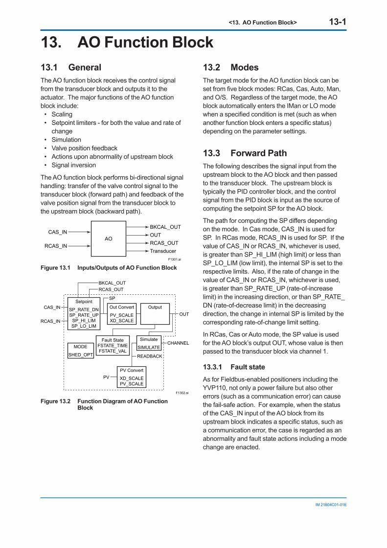
<13. AO Function Block> 13-1
IM 21B04C01-01E
13. AO Function Block13.1 GeneralThe AO function block receives the control signal from the transducer block and outputs it to the actuator. The major functions of the AO function block include:
• Scaling• Setpoint limiters - for both the value and rate of
change• Simulation• Valve position feedback• Actions upon abnormality of upstream block• Signal inversion
The AO function block performs bi-directional signal handling: transfer of the valve control signal to the transducer block (forward path) and feedback of the valve position signal from the transducer block to the upstream block (backward path).
F1301.ai
AO
TransducerRCAS_OUTRCAS_IN
CAS_INBKCAL_OUTOUT
Figure 13.1 Inputs/Outputs of AO Function Block
F1302.ai
Setpoint
SP_RATE_DNSP_RATE_UP
SP_HI_LIMSP_LO_LIM
Out Convert
PV_SCALEXD_SCALE
Output
PV Convert
XD_SCALEPV_SCALE
Fault StateFSTATE_TIMEFSTATE_VAL
Simulate
SIMULATEMODE
SHED_OPT
RCAS_IN
PV
CAS_INOUT
CHANNEL
SP
RCAS_OUTBKCAL_OUT
READBACK
Figure 13.2 Function Diagram of AO Function Block
13.2 ModesThe target mode for the AO function block can be set from five block modes: RCas, Cas, Auto, Man, and O/S. Regardless of the target mode, the AO block automatically enters the IMan or LO mode when a specified condition is met (such as when another function block enters a specific status) depending on the parameter settings.
13.3 Forward PathThe following describes the signal input from the upstream block to the AO block and then passed to the transducer block. The upstream block is typically the PID controller block, and the control signal from the PID block is input as the source of computing the setpoint SP for the AO block.
The path for computing the SP differs depending on the mode. In Cas mode, CAS_IN is used for SP. In RCas mode, RCAS_IN is used for SP. If the value of CAS_IN or RCAS_IN, whichever is used, is greater than SP_HI_LIM (high limit) or less than SP_LO_LIM (low limit), the internal SP is set to the respective limits. Also, if the rate of change in the value of CAS_IN or RCAS_IN, whichever is used, is greater than SP_RATE_UP (rate-of-increase limit) in the increasing direction, or than SP_RATE_DN (rate-of-decrease limit) in the decreasing direction, the change in internal SP is limited by the corresponding rate-of-change limit setting.
In RCas, Cas or Auto mode, the SP value is used for the AO block’s output OUT, whose value is then passed to the transducer block via channel 1.
13.3.1 Fault stateAs for Fieldbus-enabled positioners including the YVP110, not only a power failure but also other errors (such as a communication error) can cause the fail-safe action. For example, when the status of the CAS_IN input of the AO block from its upstream block indicates a specific status, such as a communication error, the case is regarded as an abnormality and fault state actions including a mode change are enacted.
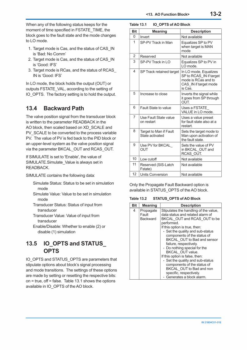
<13. AO Function Block> 13-2
IM 21B04C01-01E
When any of the following status keeps for the moment of time specified in FSTATE_TIME, the block goes to the fault state and the mode changes to LO mode.
1. Target mode is Cas, and the status of CAS_IN is ‘Bad: No Comm’
2. Target mode is Cas, and the status of CAS_IN is ‘Good: IFS’
3. Target mode is RCas, and the status of RCAS_IN is ‘Good: IFS’
In LO mode, the block holds the output (OUT) or outputs FSTATE_VAL, according to the setting of IO_OPTS. The factory setting is to hold the output.
13.4 Backward PathThe valve position signal from the transducer block is written to the parameter READBACK in the AO block, then scaled based on XD_SCALE and PV_SCALE to be converted to the process variable PV. The value of PV is fed back to the PID block or an upper-level system as the valve position signal via the parameter BKCAL_OUT and RCAS_OUT.
If SIMULATE is set to 'Enable', the value of SIMULATE.Simulate_Value is always set in READBACK.
SIMULATE contains the following data:
Simulate Status: Status to be set in simulation mode
Simulate Value: Value to be set in simulation mode
Transducer Status: Status of input from transducer
Transducer Value: Value of input from transducer
Enable/Disable: Whether to enable (2) or disable (1) simulation
13.5 IO_OPTS and STATUS_OPTS
IO_OPTS and STATUS_OPTS are parameters that stipulate options about block’s signal processing and mode transitions. The settings of these options are made by setting or resetting the respective bits: on = true, off = false. Table 13.1 shows the options available in IO_OPTS of the AO block.
Table 13.1 IO_OPTS of AO Block
Bit Meaning Description0 Invert Not available1 SP-PV Track in Man Equalizes SP to PV
when target is MAN mode
2 Reserved Not available3 SP-PV Track in LO Equalizes SP to PV in
LO mode.4 SP Track retained target In LO mode, Equalizes
SP to RCAS_IN if target mode is RCas and to CAS_IN if target mode is Cas.
5 Increase to close Inverts the signal while it goes from SP through OUT.
6 Fault State to value Uses a FSTATE_VALUE in LO mode.
7 Use Fault State value on restart
Uses a value preset for fault state also at a restart.
8 Target to Man if Fault State activated
Sets the target mode to Man upon activation of the fault state.
9 Use PV for BKCAL_OUT
Sets the value of PV in BKCAL_OUT and RCAS_OUT.
10 Low cutoff Not available11 Reserved (SIS-Latch
Fstate)Not available
12 Units Conversion Not available
Only the Propagate Fault Backward option is available in STATUS_OPTS of the AO block.
Table 13.2 STATUS_OPTS of AO Block
Bit Meaning Description 4 Propagate
Fault Backward
Stipulates the handling of the value, data status and related alarm of BKCAL_OUT and RCAS_OUT to be performed. If this option is true, then: - Set the quality and sub-status
components of the status of BKCAL_OUT to Bad and sensor failure, respectively.
- Do nothing special for the BKCAL_OUT value.
If this option is false, then: - Set the quality and sub-status
components of the status of BKCAL_OUT to Bad and non specific, respectively.
- Generates a block alarm.
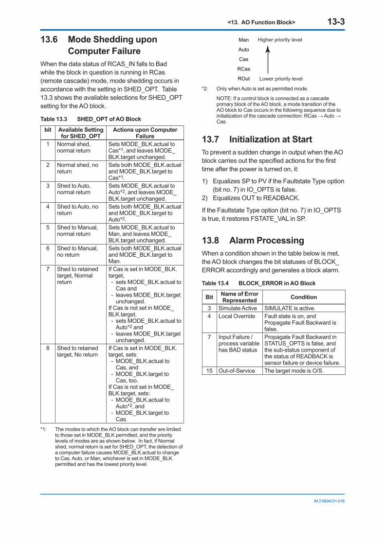
<13. AO Function Block> 13-3
IM 21B04C01-01E
13.6 Mode Shedding upon Computer Failure
When the data status of RCAS_IN falls to Bad while the block in question is running in RCas (remote cascade) mode, mode shedding occurs in accordance with the setting in SHED_OPT. Table 13.3 shows the available selections for SHED_OPT setting for the AO block.
Table 13.3 SHED_OPT of AO Block
bit Available Setting for SHED_OPT
Actions upon Computer Failure
1 Normal shed, normal return
Sets MODE_BLK.actual to Cas*1, and leaves MODE_BLK.target unchanged.
2 Normal shed, no return
Sets both MODE_BLK.actual and MODE_BLK.target to Cas*1.
3 Shed to Auto, normal return
Sets MODE_BLK.actual to Auto*2, and leaves MODE_BLK.target unchanged.
4 Shed to Auto, no return
Sets both MODE_BLK.actual and MODE_BLK.target to Auto*2.
5 Shed to Manual, normal return
Sets MODE_BLK.actual to Man, and leaves MODE_BLK.target unchanged.
6 Shed to Manual, no return
Sets both MODE_BLK.actual and MODE_BLK.target to Man.
7 Shed to retained target, Normal return
If Cas is set in MODE_BLK.target, - sets MODE_BLK.actual to
Cas and - leaves MODE_BLK.target
unchanged. If Cas is not set in MODE_BLK.target, - sets MODE_BLK.actual to
Auto*2 and - leaves MODE_BLK.target
unchanged.8 Shed to retained
target, No returnIf Cas is set in MODE_BLK.target, sets: - MODE_BLK.actual to
Cas, and - MODE_BLK.target to
Cas, too. If Cas is not set in MODE_BLK.target, sets: - MODE_BLK.actual to
Auto*2, and - MODE_BLK.target to
Cas.
*1: The modes to which the AO block can transfer are limited to those set in MODE_BLK.permitted, and the priority levels of modes are as shown below. In fact, if Normal shed, normal return is set for SHED_OPT, the detection of a computer failure causes MODE_BLK.actual to change to Cas, Auto, or Man, whichever is set in MODE_BLK.permitted and has the lowest priority level.
Man
Auto
Cas
RCas
ROut
Higher priority level
Lower priority level
*2: Only when Auto is set as permitted mode.
NOTE: If a control block is connected as a cascade primary block of the AO block, a mode transition of the AO block to Cas occurs in the following sequence due to initialization of the cascade connection: RCas → Auto → Cas.
13.7 Initialization at StartTo prevent a sudden change in output when the AO block carries out the specified actions for the first time after the power is turned on, it:
1) Equalizes SP to PV if the Faultstate Type option (bit no. 7) in IO_OPTS is false.
2) Equalizes OUT to READBACK.
If the Faultstate Type option (bit no. 7) in IO_OPTS is true, it restores FSTATE_VAL in SP.
13.8 Alarm Processing When a condition shown in the table below is met, the AO block changes the bit statuses of BLOCK_ERROR accordingly and generates a block alarm.
Table 13.4 BLOCK_ERROR in AO Block
Bit Name of Error Represented Condition
3 Simulate Active SIMULATE is active.4 Local Override Fault state is on, and
Propagate Fault Backward is false.
7 Input Failure / process variable has BAD status
Propagate Fault Backward in STATUS_OPTS is false, and the sub-status component of the status of READBACK is sensor failure or device failure.
15 Out-of-Service The target mode is O/S.
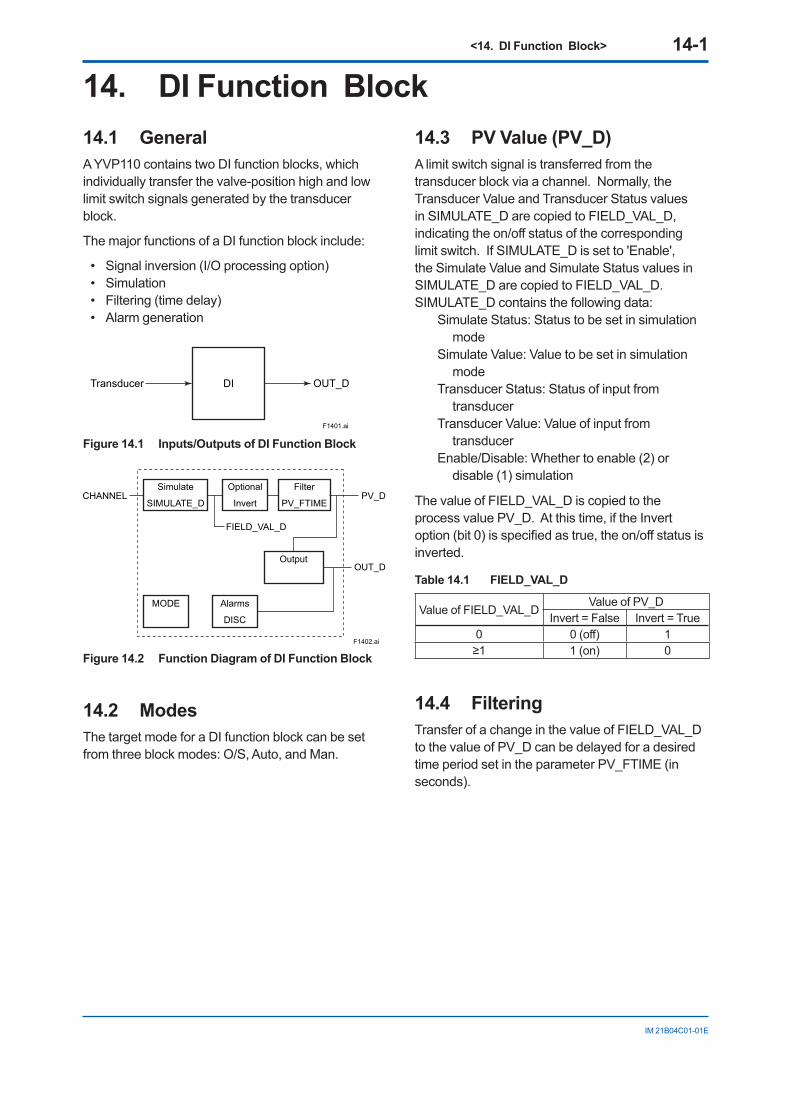
<14. DI Function Block> 14-1
IM 21B04C01-01E
14. DI Function Block14.1 GeneralA YVP110 contains two DI function blocks, which individually transfer the valve-position high and low limit switch signals generated by the transducer block.
The major functions of a DI function block include:
• Signal inversion (I/O processing option)• Simulation• Filtering (time delay)• Alarm generation
F1401.ai
DITransducer OUT_D
Figure 14.1 Inputs/Outputs of DI Function Block
F1402.ai
OutputOUT_D
FIELD_VAL_D
Simulate
SIMULATE_D
Optional
Invert
Alarms
DISC
MODE
Filter
PV_FTIMECHANNEL PV_D
Figure 14.2 Function Diagram of DI Function Block
14.2 ModesThe target mode for a DI function block can be set from three block modes: O/S, Auto, and Man.
14.3 PV Value (PV_D)A limit switch signal is transferred from the transducer block via a channel. Normally, the Transducer Value and Transducer Status values in SIMULATE_D are copied to FIELD_VAL_D, indicating the on/off status of the corresponding limit switch. If SIMULATE_D is set to 'Enable', the Simulate Value and Simulate Status values in SIMULATE_D are copied to FIELD_VAL_D.SIMULATE_D contains the following data:
Simulate Status: Status to be set in simulation mode
Simulate Value: Value to be set in simulation mode
Transducer Status: Status of input from transducer
Transducer Value: Value of input from transducer
Enable/Disable: Whether to enable (2) or disable (1) simulation
The value of FIELD_VAL_D is copied to the process value PV_D. At this time, if the Invert option (bit 0) is specified as true, the on/off status is inverted.
Table 14.1 FIELD_VAL_D
Value of FIELD_VAL_DValue of PV_D
Invert = False Invert = True0 0 (off) 1≥1 1 (on) 0
14.4 FilteringTransfer of a change in the value of FIELD_VAL_D to the value of PV_D can be delayed for a desired time period set in the parameter PV_FTIME (in seconds).
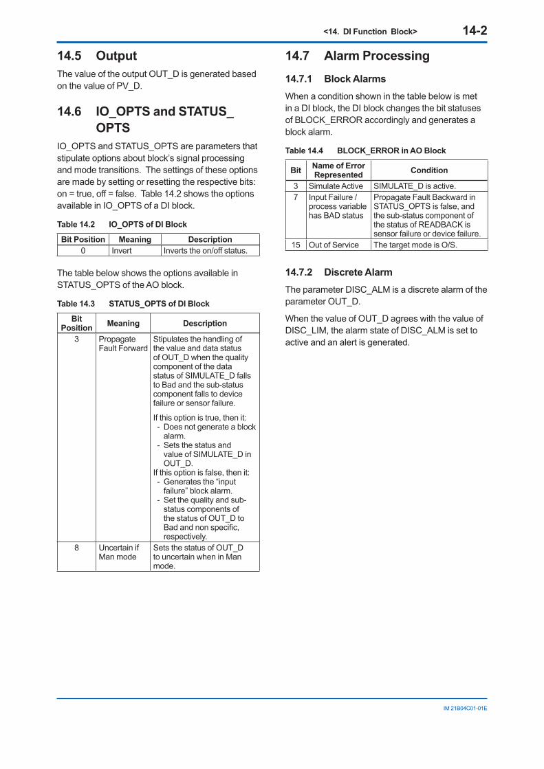
<14. DI Function Block> 14-2
IM 21B04C01-01E
14.5 OutputThe value of the output OUT_D is generated based on the value of PV_D.
14.6 IO_OPTS and STATUS_OPTS
IO_OPTS and STATUS_OPTS are parameters that stipulate options about block’s signal processing and mode transitions. The settings of these options are made by setting or resetting the respective bits: on = true, off = false. Table 14.2 shows the options available in IO_OPTS of a DI block.
Table 14.2 IO_OPTS of DI Block
Bit Position Meaning Description0 Invert Inverts the on/off status.
The table below shows the options available in STATUS_OPTS of the AO block.
Table 14.3 STATUS_OPTS of DI Block
Bit Position Meaning Description
3 Propagate Fault Forward
Stipulates the handling of the value and data status of OUT_D when the quality component of the data status of SIMULATE_D falls to Bad and the sub-status component falls to device failure or sensor failure.
If this option is true, then it: - Does not generate a block
alarm. - Sets the status and
value of SIMULATE_D in OUT_D.
If this option is false, then it: - Generates the “input
failure” block alarm. - Set the quality and sub-
status components of the status of OUT_D to Bad and non specific, respectively.
8 Uncertain if Man mode
Sets the status of OUT_D to uncertain when in Man mode.
14.7 Alarm Processing 14.7.1 Block AlarmsWhen a condition shown in the table below is met in a DI block, the DI block changes the bit statuses of BLOCK_ERROR accordingly and generates a block alarm.
Table 14.4 BLOCK_ERROR in AO Block
Bit Name of Error Represented Condition
3 Simulate Active SIMULATE_D is active.7 Input Failure /
process variable has BAD status
Propagate Fault Backward in STATUS_OPTS is false, and the sub-status component of the status of READBACK is sensor failure or device failure.
15 Out of Service The target mode is O/S.
14.7.2 Discrete AlarmThe parameter DISC_ALM is a discrete alarm of the parameter OUT_D.
When the value of OUT_D agrees with the value of DISC_LIM, the alarm state of DISC_ALM is set to active and an alert is generated.
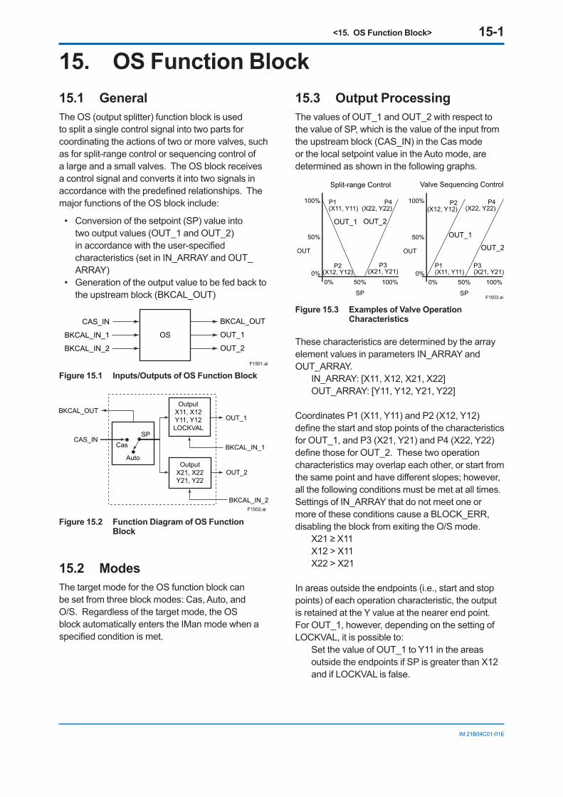
<15. OS Function Block> 15-1
IM 21B04C01-01E
15. OS Function Block15.1 GeneralThe OS (output splitter) function block is used to split a single control signal into two parts for coordinating the actions of two or more valves, such as for split-range control or sequencing control of a large and a small valves. The OS block receives a control signal and converts it into two signals in accordance with the predefined relationships. The major functions of the OS block include:
• Conversion of the setpoint (SP) value into two output values (OUT_1 and OUT_2) in accordance with the user-specified characteristics (set in IN_ARRAY and OUT_ARRAY)
• Generation of the output value to be fed back to the upstream block (BKCAL_OUT)
F1501.ai
OS
CAS_IN
BKCAL_IN_1
BKCAL_IN_2
BKCAL_OUT
OUT_1
OUT_2
Figure 15.1 Inputs/Outputs of OS Function Block
F1502.ai
OutputX21, X22Y21, Y22
BKCAL_IN_1Cas
Auto
SP
BKCAL_OUTOUT_1
CAS_IN
OUT_2
BKCAL_IN_2
OutputX11, X12Y11, Y12LOCKVAL
Figure 15.2 Function Diagram of OS Function Block
15.2 ModesThe target mode for the OS function block can be set from three block modes: Cas, Auto, and O/S. Regardless of the target mode, the OS block automatically enters the IMan mode when a specified condition is met.
15.3 Output ProcessingThe values of OUT_1 and OUT_2 with respect to the value of SP, which is the value of the input from the upstream block (CAS_IN) in the Cas mode or the local setpoint value in the Auto mode, are determined as shown in the following graphs.
F1503.ai
Split-range Control Valve Sequencing Control
100%
50%
0%
P1(X11, Y11)
OUT_1 OUT_2
P3(X21, Y21)
P2(X12, Y12)
P4(X22, Y22)
0% 50% 100%
SP
100%
50%
0%P1(X11, Y11)
OUT_1
OUT_2
P4(X22, Y22)
P2(X12, Y12)
P3(X21, Y21)
0% 50% 100%
SP
OUT OUT
Figure 15.3 Examples of Valve Operation Characteristics
These characteristics are determined by the array element values in parameters IN_ARRAY and OUT_ARRAY.
IN_ARRAY: [X11, X12, X21, X22]OUT_ARRAY: [Y11, Y12, Y21, Y22]
Coordinates P1 (X11, Y11) and P2 (X12, Y12) define the start and stop points of the characteristics for OUT_1, and P3 (X21, Y21) and P4 (X22, Y22) define those for OUT_2. These two operation characteristics may overlap each other, or start from the same point and have different slopes; however, all the following conditions must be met at all times. Settings of IN_ARRAY that do not meet one or more of these conditions cause a BLOCK_ERR, disabling the block from exiting the O/S mode.
X21 ≥ X11X12 > X11X22 > X21
In areas outside the endpoints (i.e., start and stop points) of each operation characteristic, the output is retained at the Y value at the nearer end point. For OUT_1, however, depending on the setting of LOCKVAL, it is possible to:
Set the value of OUT_1 to Y11 in the areas outside the endpoints if SP is greater than X12 and if LOCKVAL is false.
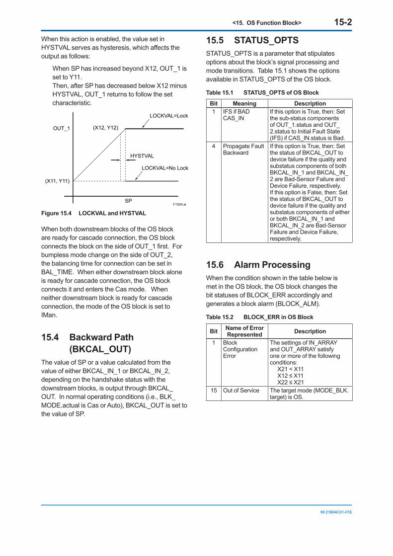
<15. OS Function Block> 15-2
IM 21B04C01-01E
When this action is enabled, the value set in HYSTVAL serves as hysteresis, which affects the output as follows:
When SP has increased beyond X12, OUT_1 is set to Y11. Then, after SP has decreased below X12 minus HYSTVAL, OUT_1 returns to follow the set characteristic.
F1504.ai
(X11, Y11)
OUT_1 (X12, Y12)
SP
HYSTVAL
LOCKVAL=No Lock
LOCKVAL=Lock
Figure 15.4 LOCKVAL and HYSTVAL
When both downstream blocks of the OS block are ready for cascade connection, the OS block connects the block on the side of OUT_1 first. For bumpless mode change on the side of OUT_2, the balancing time for connection can be set in BAL_TIME. When either downstream block alone is ready for cascade connection, the OS block connects it and enters the Cas mode. When neither downstream block is ready for cascade connection, the mode of the OS block is set to IMan.
15.4 Backward Path (BKCAL_OUT)
The value of SP or a value calculated from the value of either BKCAL_IN_1 or BKCAL_IN_2, depending on the handshake status with the downstream blocks, is output through BKCAL_OUT. In normal operating conditions (i.e., BLK_MODE.actual is Cas or Auto), BKCAL_OUT is set to the value of SP.
15.5 STATUS_OPTS STATUS_OPTS is a parameter that stipulates options about the block’s signal processing and mode transitions. Table 15.1 shows the options available in STATUS_OPTS of the OS block.
Table 15.1 STATUS_OPTS of OS Block
Bit Meaning Description1 IFS if BAD
CAS_INIf this option is True, then: Set the sub-status components of OUT_1.status and OUT_2.status to Initial Fault State (IFS) if CAS_IN.status is Bad.
4 Propagate Fault Backward
If this option is True, then: Set the status of BKCAL_OUT to device failure if the quality and substatus components of both BKCAL_IN_1 and BKCAL_IN_2 are Bad-Sensor Failure and Device Failure, respectively.If this option is False, then: Set the status of BKCAL_OUT to device failure if the quality and substatus components of either or both BKCAL_IN_1 and BKCAL_IN_2 are Bad-Sensor Failure and Device Failure, respectively.
15.6 Alarm Processing When the condition shown in the table below is met in the OS block, the OS block changes the bit statuses of BLOCK_ERR accordingly and generates a block alarm (BLOCK_ALM).
Table 15.2 BLOCK_ERR in OS Block
Bit Name of ErrorRepresented Description
1 Block Configuration Error
The settings of IN_ARRAY and OUT_ARRAY satisfy one or more of the following conditions: X21 < X11 X12 ≤ X11 X22 ≤ X21
15 Out of Service The target mode (MODE_BLK.target) is OS.
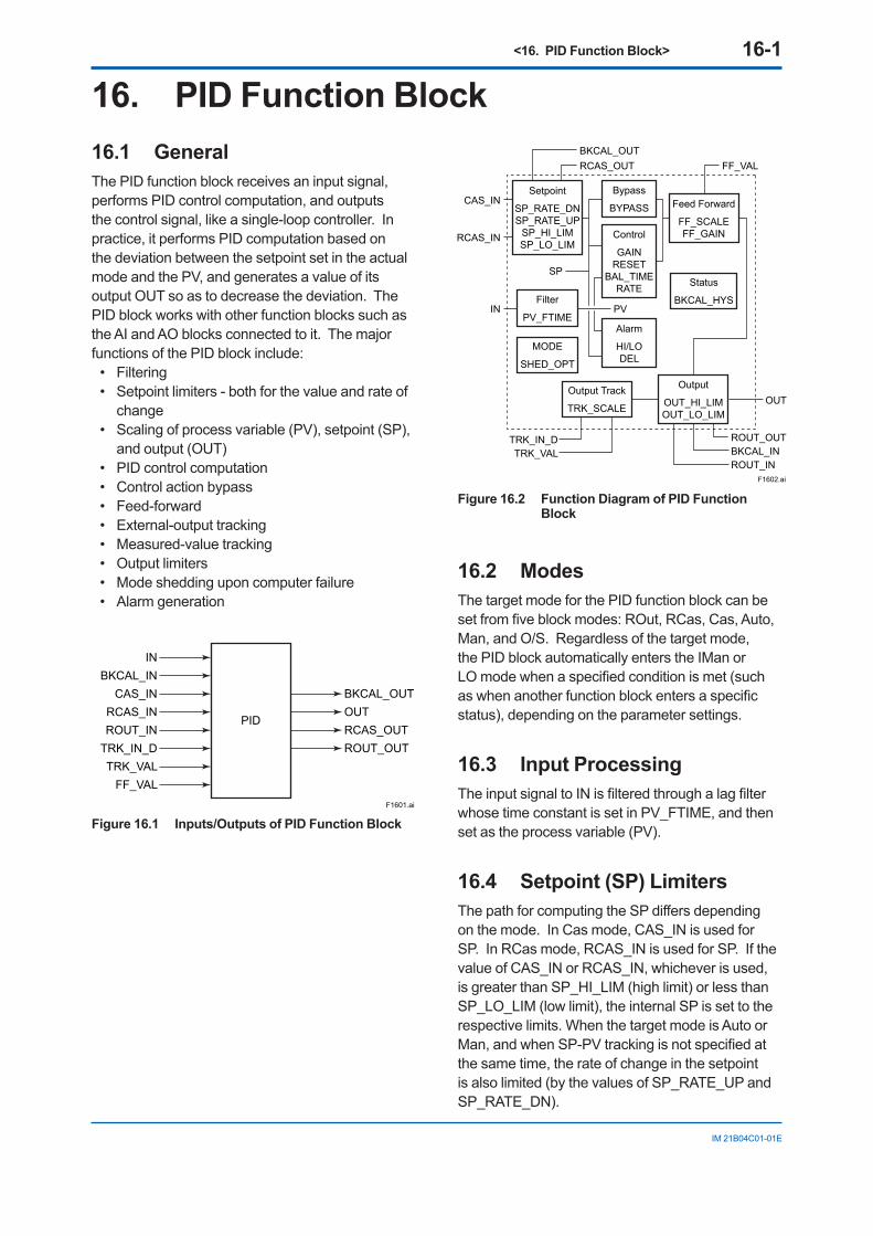
<16. PID Function Block> 16-1
IM 21B04C01-01E
16. PID Function Block16.1 GeneralThe PID function block receives an input signal, performs PID control computation, and outputs the control signal, like a single-loop controller. In practice, it performs PID computation based on the deviation between the setpoint set in the actual mode and the PV, and generates a value of its output OUT so as to decrease the deviation. The PID block works with other function blocks such as the AI and AO blocks connected to it. The major functions of the PID block include:
• Filtering• Setpoint limiters - both for the value and rate of
change• Scaling of process variable (PV), setpoint (SP),
and output (OUT)• PID control computation• Control action bypass• Feed-forward • External-output tracking• Measured-value tracking• Output limiters• Mode shedding upon computer failure• Alarm generation
F1601.ai
PID
FF_VAL
ROUT_OUTTRK_VAL
RCAS_OUTTRK_IN_D
OUTROUT_INRCAS_INCAS_IN
BKCAL_ININ
BKCAL_OUT
Figure 16.1 Inputs/Outputs of PID Function Block
F1602.ai
OUT
ROUT_OUT
FF_VALRCAS_OUTBKCAL_OUT
BKCAL_INTRK_IN_DTRK_VAL
ROUT_IN
Setpoint
SP_RATE_DNSP_RATE_UP
SP_HI_LIMSP_LO_LIM
Bypass
BYPASS Feed Forward
FF_SCALEFF_GAIN
Status
BKCAL_HYS
Output Track
TRK_SCALE
Filter
PV_FTIME
MODE
SHED_OPT
Output
OUT_HI_LIMOUT_LO_LIM
Control
GAINRESET
BAL_TIMERATE
Alarm
HI/LODEL
CAS_IN
RCAS_IN
SP
IN PV
Figure 16.2 Function Diagram of PID Function Block
16.2 ModesThe target mode for the PID function block can be set from five block modes: ROut, RCas, Cas, Auto, Man, and O/S. Regardless of the target mode, the PID block automatically enters the IMan or LO mode when a specified condition is met (such as when another function block enters a specific status), depending on the parameter settings.
16.3 Input ProcessingThe input signal to IN is filtered through a lag filter whose time constant is set in PV_FTIME, and then set as the process variable (PV).
16.4 Setpoint (SP) LimitersThe path for computing the SP differs depending on the mode. In Cas mode, CAS_IN is used for SP. In RCas mode, RCAS_IN is used for SP. If the value of CAS_IN or RCAS_IN, whichever is used, is greater than SP_HI_LIM (high limit) or less than SP_LO_LIM (low limit), the internal SP is set to the respective limits. When the target mode is Auto or Man, and when SP-PV tracking is not specified at the same time, the rate of change in the setpoint is also limited (by the values of SP_RATE_UP and SP_RATE_DN).
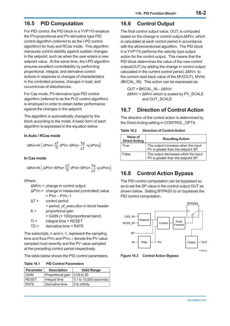
<16. PID Function Block> 16-2
IM 21B04C01-01E
16.5 PID ComputationFor PID control, the PID block in a YVP110 employs the PV-proportional and PV-derivative type PID control algorithm (referred to as the I-PD control algorithm) for Auto and RCas mode. This algorithm mensures control stability against sudden changes in the setpoint, such as when the user enters a new setpoint value. At the same time, the I-PD algorithm ensures excellent controllability by performing proportional, integral, and derivative control actions in response to changes of characteristics in the controlled process, changes in load, and occurrences of disturbances.
For Cas mode, PV-derivative type PID control algorithm (referred to as the PI-D control algorithm) is employed in order to obtain better performance against the changes in the setpoint.
The algorithm is automatically changed by the block according to the mode. A basic form of each algorithm is expressed in the equation below.
In Auto / RCas mode
∆MVn=K ∆PVn+ ∆(∆PVn)∆TTi
Td∆T
(PVn−SPn)+
In Cas mode
∆MVn=K ∆(PVn−SPn)+ ∆(∆PVn)∆TTi
Td∆T
(PVn−SPn)+
Where ; ΔMVn = change in control outputΔPVn = change in measured (controlled) value
= PVn – PVn–1ΔT = control period
= period_of_execution in block headerK = proportional gain
= GAIN (= 100/proportional band)TI = integral time = RESETTD = derivative time = RATE
The subscripts, n and n–1, represent the sampling time and thus PVn and PVn–1 denote the PV value sampled most recently and the PV value sampled at the preceding control period respectively.
The table below shows the PID control parameters.
Table 16.1 PID Control Parameters
Parameter Description Valid RangeGAIN Proportional gain 0.05 to 20RESET Integral time 0.1 to 10,000 (seconds)RATE Derivative time 0 to infinity
16.6 Control OutputThe final control output value, OUT, is computed based on the change in control output ΔMVn, which is calculated at each control period in accordance with the aforementioned algorithm. The PID block in a YVP110 performs the velocity type output action for the control output. This means that the PID block determines the value of the new control output(OUT) by adding the change in control output calculated in the current control period, ΔMVn, to the current read-back value of the MV(OUT), MVRB (BKCAL_IN). This action can be expressed as:
OUT = BKCAL_IN – ΔMVn'ΔMVn' = ΔMVn which is scaled by PV_SCALE and OUT_SCALE
16.7 Direction of Control ActionThe direction of the control action is determined by the Direct Acting setting in CONTROL_OPTS.
Table 16.2 Direction of Control Action
Value of Direct Acting Resulting Action
True The output increases when the input PV is greater than the setpoint SP.
False The output decreases when the input PV is greater than the setpoint SP.
16.8 Control Action BypassThe PID control computation can be bypassed so as to set the SP value in the control output OUT as shown below. Setting BYPASS to on bypasses the PID control computation.
F1603.ai
SetpointRCAS_IN
OUT
SP
CAS_IN
FilterIN PV
Control
BYPASS
FeedForward
Output
Figure 16.3 Control Action Bypass
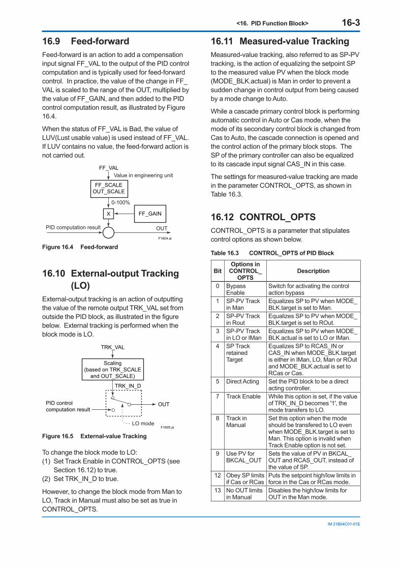
<16. PID Function Block> 16-3
IM 21B04C01-01E
16.9 Feed-forwardFeed-forward is an action to add a compensation input signal FF_VAL to the output of the PID control computation and is typically used for feed-forward control. In practice, the value of the change in FF_VAL is scaled to the range of the OUT, multiplied by the value of FF_GAIN, and then added to the PID control computation result, as illustrated by Figure 16.4.
When the status of FF_VAL is Bad, the value of LUV(Lust usable value) is used instead of FF_VAL. If LUV contains no value, the feed-forward action is not carried out.
F1604.ai
FF_SCALEOUT_SCALE
FF_GAIN
Value in engineering unit
PID computation result OUT
0-100%
FF_VAL
X
Figure 16.4 Feed-forward
16.10 External-output Tracking (LO)
External-output tracking is an action of outputting the value of the remote output TRK_VAL set from outside the PID block, as illustrated in the figure below. External tracking is performed when the block mode is LO.
F1605.ai
Scaling(based on TRK_SCALE
and OUT_SCALE)
PID control computation result
OUT
TRK_IN_D
TRK_VAL
LO mode
Figure 16.5 External-value Tracking
To change the block mode to LO: (1) Set Track Enable in CONTROL_OPTS (see
Section 16.12) to true. (2) Set TRK_IN_D to true.
However, to change the block mode from Man to LO, Track in Manual must also be set as true in CONTROL_OPTS.
16.11 Measured-value TrackingMeasured-value tracking, also referred to as SP-PV tracking, is the action of equalizing the setpoint SP to the measured value PV when the block mode (MODE_BLK.actual) is Man in order to prevent a sudden change in control output from being caused by a mode change to Auto.
While a cascade primary control block is performing automatic control in Auto or Cas mode, when the mode of its secondary control block is changed from Cas to Auto, the cascade connection is opened and the control action of the primary block stops. The SP of the primary controller can also be equalized to its cascade input signal CAS_IN in this case.
The settings for measured-value tracking are made in the parameter CONTROL_OPTS, as shown in Table 16.3.
16.12 CONTROL_OPTSCONTROL_OPTS is a parameter that stipulates control options as shown below.
Table 16.3 CONTROL_OPTS of PID Block
BitOptions in
CONTROL_OPTS
Description
0 Bypass Enable
Switch for activating the control action bypass
1 SP-PV Track in Man
Equalizes SP to PV when MODE_BLK.target is set to Man.
2 SP-PV Track in Rout
Equalizes SP to PV when MODE_BLK.target is set to ROut.
3 SP-PV Track in LO or IMan
Equalizes SP to PV when MODE_BLK.actual is set to LO or IMan.
4 SP Track retained Target
Equalizes SP to RCAS_IN or CAS_IN when MODE_BLK.target is either in IMan, LO, Man or ROut and MODE_BLK.actual is set to RCas or Cas.
5 Direct Acting Set the PID block to be a direct acting controller.
7 Track Enable While this option is set, if the value of TRK_IN_D becomes '1', the mode transfers to LO.
8 Track in Manual
Set this option when the mode should be transfered to LO even when MODE_BLK.target is set to Man. This option is invalid when Track Enable option is not set.
9 Use PV for BKCAL_OUT
Sets the value of PV in BKCAL_OUT and RCAS_OUT, instead of the value of SP.
12 Obey SP limits if Cas or RCas
Puts the setpoint high/low limits in force in the Cas or RCas mode.
13 No OUT limits in Manual
Disables the high/low limits for OUT in the Man mode.
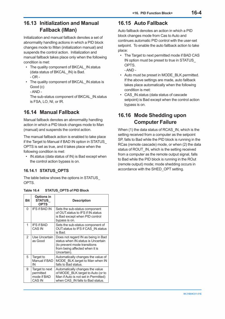
<16. PID Function Block> 16-4
IM 21B04C01-01E
16.13 Initialization and Manual Fallback (IMan)
Initialization and manual fallback denotes a set of abnormality handling actions in which a PID block changes mode to IMan (initialization manual) and suspends the control action. Initialization and manual fallback takes place only when the following condition is met:
• The quality component of BKCAL_IN.status (data status of BKCAL_IN) is Bad.
- OR -• The quality component of BKCAL_IN.status is
Good (c) - AND - The sub-status component of BKCAL_IN.status
is FSA, LO, NI, or IR.
16.14 Manual FallbackManual fallback denotes an abnormality handling action in which a PID block changes mode to Man (manual) and suspends the control action.
The manual fallback action is enabled to take place if the Target to Manual if BAD IN option in STATUS_OPTS is set as true, and it takes place when the following condition is met:
• IN.status (data status of IN) is Bad except when the control action bypass is on.
16.14.1 STATUS_OPTSThe table below shows the options in STATUS_OPTS.
Table 16.4 STATUS_OPTS of PID Block
BitOptions in STATUS_
OPTSDescription
0 IFS if BAD IN Sets the sub-status component of OUT.status to IFS if IN.status is Bad except when PID control bypass is on.
1 IFS if BAD CAS IN
Sets the sub-status component of OUT.status to IFS if CAS_IN.status is Bad.
2 Use Uncertain as Good
Does not regard IN as being in Bad status when IN.status is Uncertain (to prevent mode transitions from being affected when it is Uncertain).
5 Target to Manual if BAD IN
Automatically changes the value of MODE_BLK.target to Man when IN falls to Bad status.
9 Target to next permitted mode if BAD CAS IN
Automatically changes the value of MODE_BLK.target to Auto (or to Man if Auto is not set in Permitted) when CAS_IN falls to Bad status.
16.15 Auto FallbackAuto fallback denotes an action in which a PID block changes mode from Cas to Auto and continues automatic PID control with the user-set setpoint. To enable the auto fallback action to take place:
• The Target to next permitted mode if BAD CAS IN option must be preset to true in STATUS_OPTS.
- AND -• Auto must be preset in MODE_BLK.permitted. If the above settings are made, auto fallback
takes place automatically when the following condition is met:
• CAS_IN.status (data status of cascade setpoint) is Bad except when the control action bypass is on.
16.16 Mode Shedding upon Computer Failure
When (1) the data status of RCAS_IN, which is the setting received from a computer as the setpoint SP, falls to Bad while the PID block is running in the RCas (remote cascade) mode, or when (2) the data status of ROUT_IN, which is the setting received from a computer as the remote output signal, falls to Bad while the PID block is running in the ROut (remote output) mode; mode shedding occurs in accordance with the SHED_OPT setting.
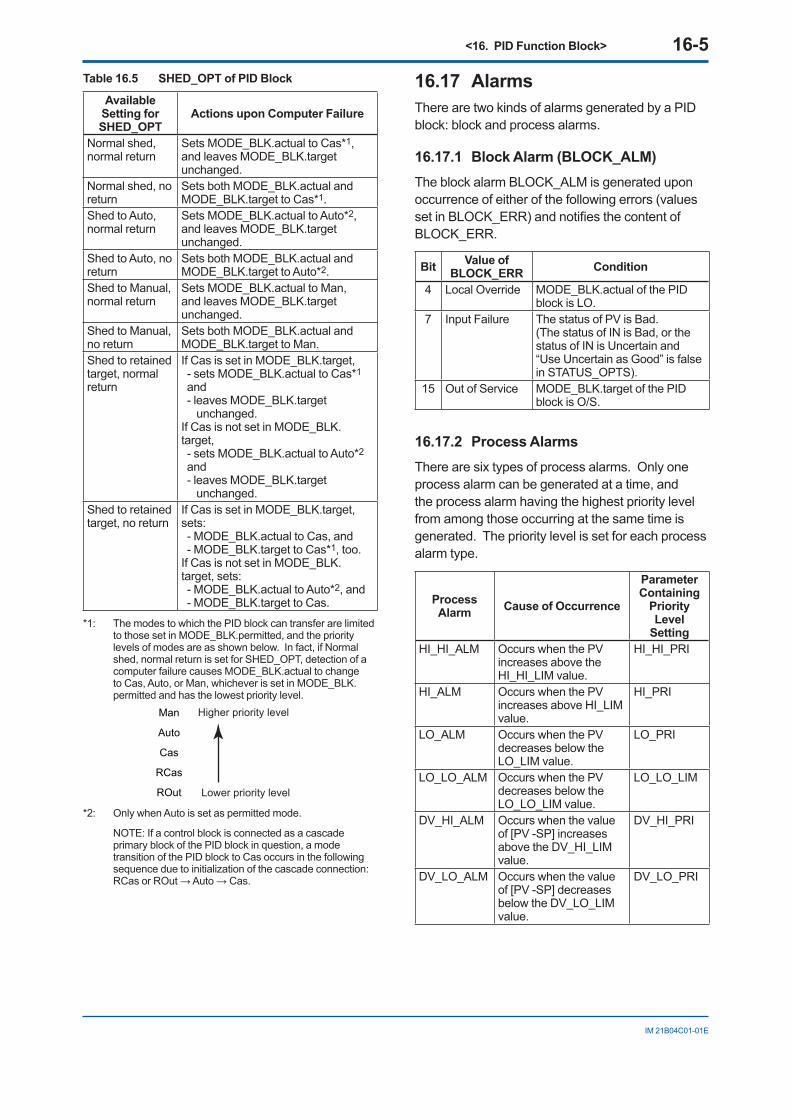
<16. PID Function Block> 16-5
IM 21B04C01-01E
Table 16.5 SHED_OPT of PID Block
Available Setting for SHED_OPT
Actions upon Computer Failure
Normal shed, normal return
Sets MODE_BLK.actual to Cas*1, and leaves MODE_BLK.target unchanged.
Normal shed, no return
Sets both MODE_BLK.actual and MODE_BLK.target to Cas*1.
Shed to Auto, normal return
Sets MODE_BLK.actual to Auto*2, and leaves MODE_BLK.target unchanged.
Shed to Auto, no return
Sets both MODE_BLK.actual and MODE_BLK.target to Auto*2.
Shed to Manual, normal return
Sets MODE_BLK.actual to Man, and leaves MODE_BLK.target unchanged.
Shed to Manual, no return
Sets both MODE_BLK.actual and MODE_BLK.target to Man.
Shed to retained target, normal return
If Cas is set in MODE_BLK.target, - sets MODE_BLK.actual to Cas*1 and - leaves MODE_BLK.target
unchanged. If Cas is not set in MODE_BLK.target, - sets MODE_BLK.actual to Auto*2 and - leaves MODE_BLK.target
unchanged.Shed to retained target, no return
If Cas is set in MODE_BLK.target, sets: - MODE_BLK.actual to Cas, and - MODE_BLK.target to Cas*1, too.
If Cas is not set in MODE_BLK.target, sets: - MODE_BLK.actual to Auto*2, and - MODE_BLK.target to Cas.
*1: The modes to which the PID block can transfer are limited to those set in MODE_BLK.permitted, and the priority levels of modes are as shown below. In fact, if Normal shed, normal return is set for SHED_OPT, detection of a computer failure causes MODE_BLK.actual to change to Cas, Auto, or Man, whichever is set in MODE_BLK.permitted and has the lowest priority level.
Man
Auto
Cas
RCas
ROut
Higher priority level
Lower priority level
*2: Only when Auto is set as permitted mode.
NOTE: If a control block is connected as a cascade primary block of the PID block in question, a mode transition of the PID block to Cas occurs in the following sequence due to initialization of the cascade connection: RCas or ROut → Auto → Cas.
16.17 AlarmsThere are two kinds of alarms generated by a PID block: block and process alarms.
16.17.1 Block Alarm (BLOCK_ALM)The block alarm BLOCK_ALM is generated upon occurrence of either of the following errors (values set in BLOCK_ERR) and notifies the content of BLOCK_ERR.
Bit Value of BLOCK_ERR Condition
4 Local Override MODE_BLK.actual of the PID block is LO.
7 Input Failure The status of PV is Bad.(The status of IN is Bad, or the status of IN is Uncertain and “Use Uncertain as Good” is false in STATUS_OPTS).
15 Out of Service MODE_BLK.target of the PID block is O/S.
16.17.2 Process AlarmsThere are six types of process alarms. Only one process alarm can be generated at a time, and the process alarm having the highest priority level from among those occurring at the same time is generated. The priority level is set for each process alarm type.
Process Alarm Cause of Occurrence
Parameter Containing
Priority Level
SettingHI_HI_ALM Occurs when the PV
increases above the HI_HI_LIM value.
HI_HI_PRI
HI_ALM Occurs when the PV increases above HI_LIM value.
HI_PRI
LO_ALM Occurs when the PV decreases below the LO_LIM value.
LO_PRI
LO_LO_ALM Occurs when the PV decreases below the LO_LO_LIM value.
LO_LO_LIM
DV_HI_ALM Occurs when the value of [PV -SP] increases above the DV_HI_LIM value.
DV_HI_PRI
DV_LO_ALM Occurs when the value of [PV -SP] decreases below the DV_LO_LIM value.
DV_LO_PRI
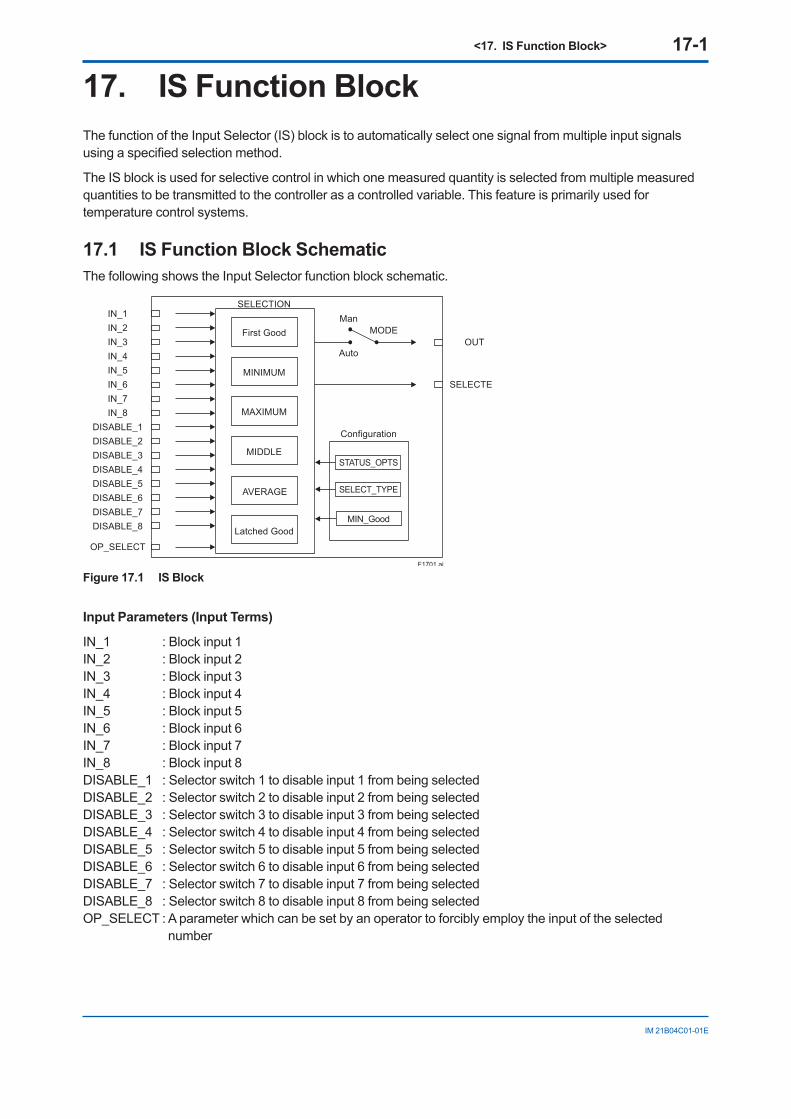
<17. IS Function Block> 17-1
IM 21B04C01-01E
17. IS Function BlockThe function of the Input Selector (IS) block is to automatically select one signal from multiple input signals using a specified selection method.
The IS block is used for selective control in which one measured quantity is selected from multiple measured quantities to be transmitted to the controller as a controlled variable. This feature is primarily used for temperature control systems.
17.1 IS Function Block SchematicThe following shows the Input Selector function block schematic.
IN_1
Configuration
Auto
ManMODE
SELECTED
OUT
STATUS_OPTS
SELECT_TYPE
MIN_Good
IN_2IN_3IN_4IN_5IN_6IN_7IN_8
DISABLE_1DISABLE_2DISABLE_3DISABLE_4DISABLE_5DISABLE_6DISABLE_7DISABLE_8
OP_SELECT
F1701.ai
SELECTION
First Good
MINIMUM
MAXIMUM
MIDDLE
Latched Good
AVERAGE
Figure 17.1 IS Block
Input Parameters (Input Terms)
IN_1 : Block input 1 IN_2 : Block input 2 IN_3 : Block input 3 IN_4 : Block input 4 IN_5 : Block input 5 IN_6 : Block input 6 IN_7 : Block input 7 IN_8 : Block input 8 DISABLE_1 : Selector switch 1 to disable input 1 from being selected DISABLE_2 : Selector switch 2 to disable input 2 from being selected DISABLE_3 : Selector switch 3 to disable input 3 from being selected DISABLE_4 : Selector switch 4 to disable input 4 from being selected DISABLE_5 : Selector switch 5 to disable input 5 from being selected DISABLE_6 : Selector switch 6 to disable input 6 from being selected DISABLE_7 : Selector switch 7 to disable input 7 from being selected DISABLE_8 : Selector switch 8 to disable input 8 from being selected OP_SELECT : A parameter which can be set by an operator to forcibly employ the input of the selected
number
<17. IS Function Block> 17-2
IM 21B04C01-01E
Output Parameters (Computation or Selection Results)
OUT: Block output SELECTED: Indicates the input number selected using the alternatives.
Other Parameters
OUT_RANGE : Sets the OUT range. This setting does not affect instrument action.STATUS_OPTS : Option used to specify the handling of various statuses. SELECT_TYPE : Determines the input selection algorithm. MIN_GOOD : Parameter specifying the minimum required number of inputs with “good” status. If the
number of inputs that are “good” is less than the value of MIN_GOOD, input selection is canceled.
Mode
O/S : Allows configuration change, but disables input value output. Man : Allows internal processing, but the output value may vary depending on the definition of usage
conditions. Auto : Outputs the input value.
The Input Selector (IS) block offers a maximum of eight input alternatives and generates the output according to the configured action. This block generally receives inputs from the Analog Input (AI) function block. The function of the IS block is to select a maximum, minimum, middle, average, “first good,” or “latched good” signal. The block combines parameter configuration (DISABLE_n) and option (“first good”) to give priority to alternative(s) or to function as a rotary position switch. When used as a rotary position switch, the block can receive operator inputs or switch information from connected inputs.
The IS block supports the concept of middle selection. This function outputs the average of two middle signals if even multiple valid signals are configured or a middle signal if odd multiple valid signals are configured. Application of the block is to supply a selected control signal in the forward path.
The SELECTED parameter is the 2nd output indicating which input has been selected using the algorithm.
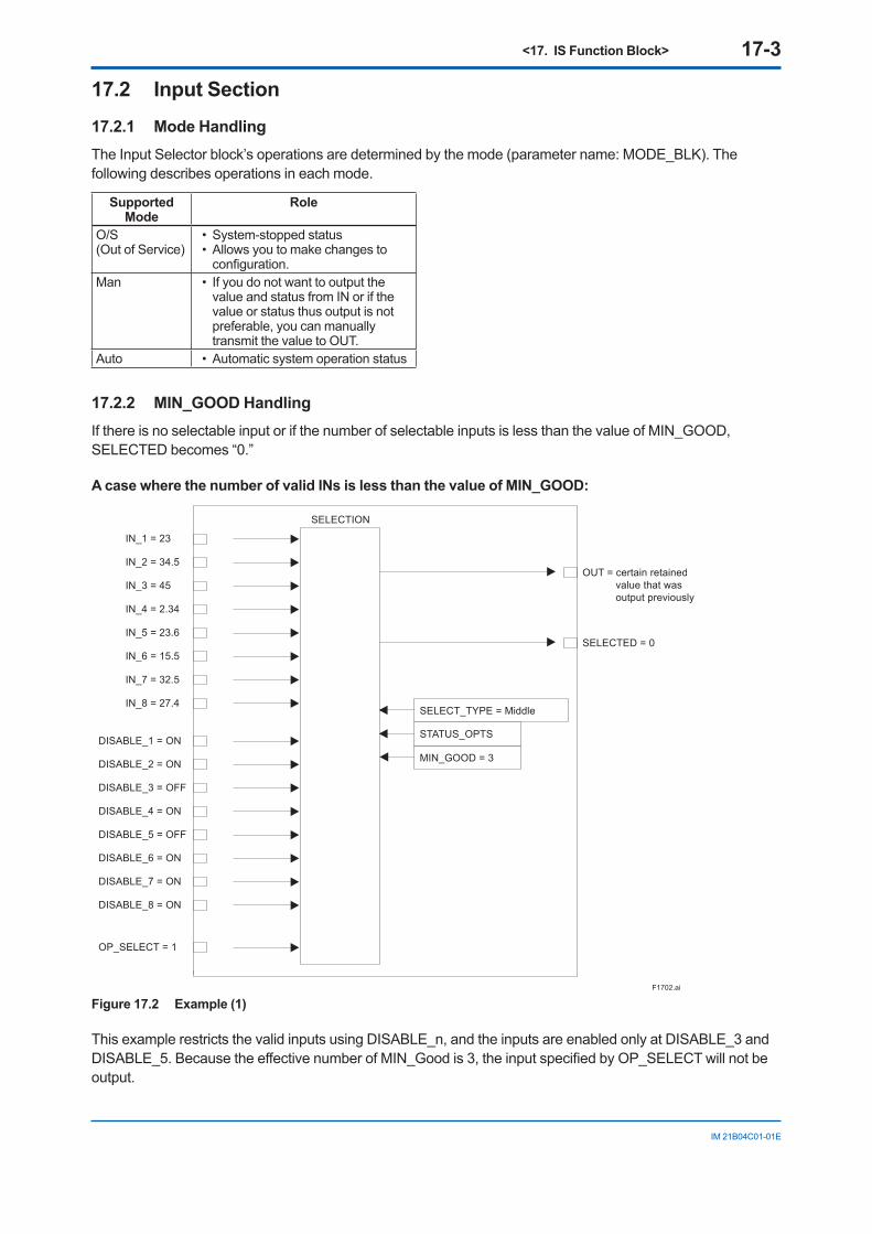
<17. IS Function Block> 17-3
IM 21B04C01-01E
17.2 Input Section 17.2.1 Mode Handling The Input Selector block’s operations are determined by the mode (parameter name: MODE_BLK). The following describes operations in each mode.
Supported Mode
Role
O/S(Out of Service)
• System-stopped status• Allows you to make changes to
configuration.Man • If you do not want to output the
value and status from IN or if the value or status thus output is not preferable, you can manually transmit the value to OUT.
Auto • Automatic system operation status
17.2.2 MIN_GOOD Handling If there is no selectable input or if the number of selectable inputs is less than the value of MIN_GOOD, SELECTED becomes “0.”
A case where the number of valid INs is less than the value of MIN_GOOD:
F1702.ai
OUT = certain retained value that was output previously
IN_1 = 23
SELECT_TYPE = Middle
STATUS_OPTS
MIN_GOOD = 3
SELECTION
SELECTED = 0
IN_2 = 34.5
IN_3 = 45
IN_4 = 2.34
IN_5 = 23.6
IN_6 = 15.5
IN_7 = 32.5
IN_8 = 27.4
DISABLE_1 = ON
DISABLE_2 = ON
DISABLE_3 = OFF
DISABLE_4 = ON
DISABLE_5 = OFF
DISABLE_6 = ON
DISABLE_7 = ON
DISABLE_8 = ON
OP_SELECT = 1
Figure 17.2 Example (1)
This example restricts the valid inputs using DISABLE_n, and the inputs are enabled only at DISABLE_3 and DISABLE_5. Because the effective number of MIN_Good is 3, the input specified by OP_SELECT will not be output.
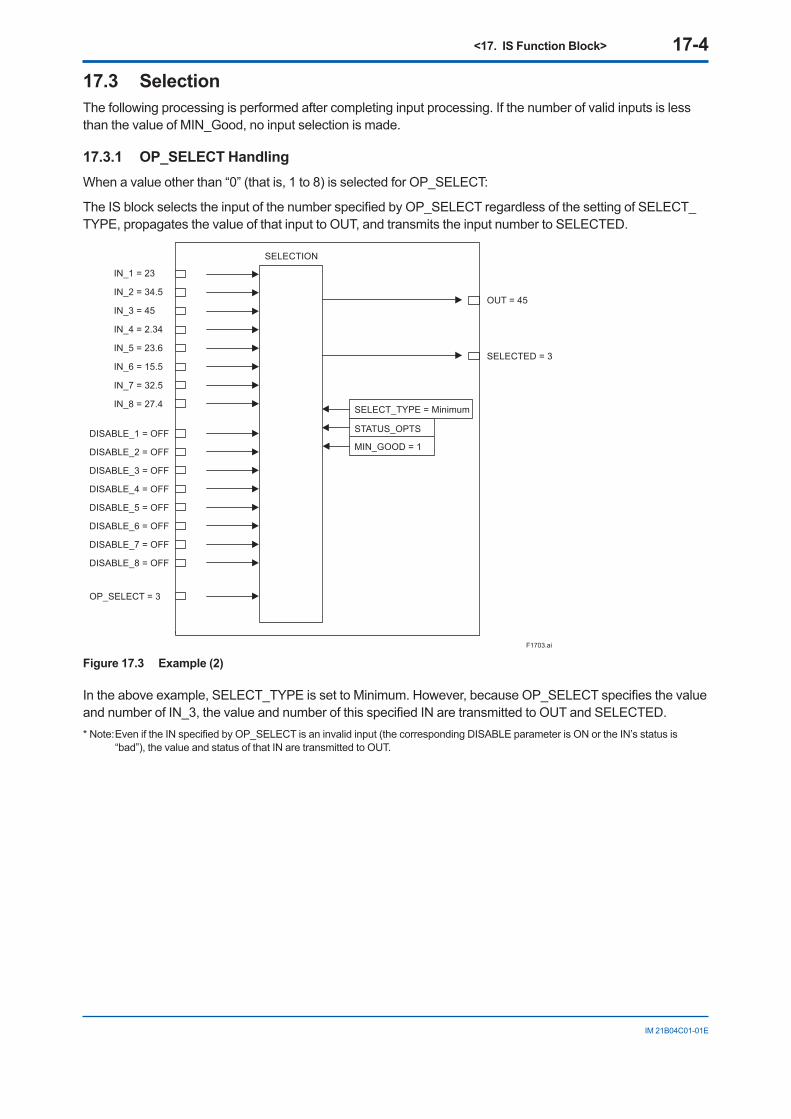
<17. IS Function Block> 17-4
IM 21B04C01-01E
17.3 Selection The following processing is performed after completing input processing. If the number of valid inputs is less than the value of MIN_Good, no input selection is made.
17.3.1 OP_SELECT Handling When a value other than “0” (that is, 1 to 8) is selected for OP_SELECT:
The IS block selects the input of the number specified by OP_SELECT regardless of the setting of SELECT_TYPE, propagates the value of that input to OUT, and transmits the input number to SELECTED.
IN_1 = 23
SELECT_TYPE = Minimum
STATUS_OPTS
MIN_GOOD = 1
SELECTION
SELECTED = 3
OUT = 45IN_2 = 34.5
IN_3 = 45
IN_4 = 2.34
IN_5 = 23.6
IN_6 = 15.5
IN_7 = 32.5
IN_8 = 27.4
DISABLE_1 = OFF
DISABLE_2 = OFF
DISABLE_3 = OFF
DISABLE_4 = OFF
DISABLE_5 = OFF
DISABLE_6 = OFF
DISABLE_7 = OFF
DISABLE_8 = OFF
OP_SELECT = 3
F1703.ai
Figure 17.3 Example (2)
In the above example, SELECT_TYPE is set to Minimum. However, because OP_SELECT specifies the value and number of IN_3, the value and number of this specified IN are transmitted to OUT and SELECTED. * Note: Even if the IN specified by OP_SELECT is an invalid input (the corresponding DISABLE parameter is ON or the IN’s status is
“bad”), the value and status of that IN are transmitted to OUT.
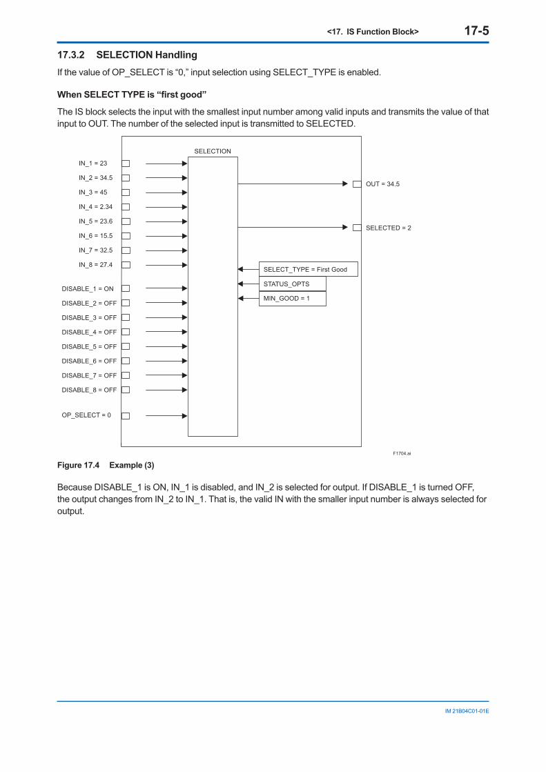
<17. IS Function Block> 17-5
IM 21B04C01-01E
17.3.2 SELECTION Handling If the value of OP_SELECT is “0,” input selection using SELECT_TYPE is enabled.
When SELECT TYPE is “first good”
The IS block selects the input with the smallest input number among valid inputs and transmits the value of that input to OUT. The number of the selected input is transmitted to SELECTED.
IN_1 = 23
SELECT_TYPE = First Good
STATUS_OPTS
MIN_GOOD = 1
SELECTION
SELECTED = 2
OUT = 34.5IN_2 = 34.5
IN_3 = 45
IN_4 = 2.34
IN_5 = 23.6
IN_6 = 15.5
IN_7 = 32.5
IN_8 = 27.4
DISABLE_1 = ON
DISABLE_2 = OFF
DISABLE_3 = OFF
DISABLE_4 = OFF
DISABLE_5 = OFF
DISABLE_6 = OFF
DISABLE_7 = OFF
DISABLE_8 = OFF
OP_SELECT = 0
F1704.ai
Figure 17.4 Example (3)
Because DISABLE_1 is ON, IN_1 is disabled, and IN_2 is selected for output. If DISABLE_1 is turned OFF, the output changes from IN_2 to IN_1. That is, the valid IN with the smaller input number is always selected for output.
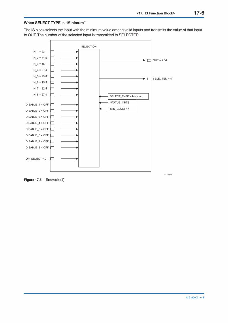
<17. IS Function Block> 17-6
IM 21B04C01-01E
When SELECT TYPE is “Minimum”
The IS block selects the input with the minimum value among valid inputs and transmits the value of that input to OUT. The number of the selected input is transmitted to SELECTED.
IN_1 = 23
SELECT_TYPE = Minimum
STATUS_OPTS
MIN_GOOD = 1
SELECTION
SELECTED = 4
OUT = 2.34IN_2 = 34.5
IN_3 = 45
IN_4 = 2.34
IN_5 = 23.6
IN_6 = 15.5
IN_7 = 32.5
IN_8 = 27.4
DISABLE_1 = OFF
DISABLE_2 = OFF
DISABLE_3 = OFF
DISABLE_4 = OFF
DISABLE_5 = OFF
DISABLE_6 = OFF
DISABLE_7 = OFF
DISABLE_8 = OFF
OP_SELECT = 0
F1705.ai
Figure 17.5 Example (4)
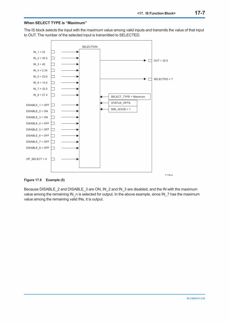
<17. IS Function Block> 17-7
IM 21B04C01-01E
When SELECT TYPE is “Maximum”
The IS block selects the input with the maximum value among valid inputs and transmits the value of that input to OUT. The number of the selected input is transmitted to SELECTED.
IN_1 = 23
SELECT_TYPE = Maximum
STATUS_OPTS
MIN_GOOD = 1
SELECTION
SELECTED = 7
OUT = 32.5IN_2 = 34.5
IN_3 = 45
IN_4 = 2.34
IN_5 = 23.6
IN_6 = 15.5
IN_7 = 32.5
IN_8 = 27.4
DISABLE_1 = OFF
DISABLE_2 = ON
DISABLE_3 = ON
DISABLE_4 = OFF
DISABLE_5 = OFF
DISABLE_6 = OFF
DISABLE_7 = OFF
DISABLE_8 = OFF
OP_SELECT = 0
F1706.ai
Figure 17.6 Example (5)
Because DISABLE_2 and DISABLE_3 are ON, IN_2 and IN_3 are disabled, and the IN with the maximum value among the remaining IN_n is selected for output. In the above example, since IN_7 has the maximum value among the remaining valid INs, it is output.
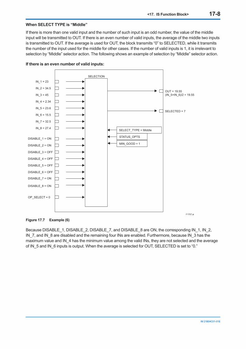
<17. IS Function Block> 17-8
IM 21B04C01-01E
When SELECT TYPE is “Middle”
If there is more than one valid input and the number of such input is an odd number, the value of the middle input will be transmitted to OUT. If there is an even number of valid inputs, the average of the middle two inputs is transmitted to OUT. If the average is used for OUT, the block transmits “0” to SELECTED, while it transmits the number of the input used for the middle for other cases. If the number of valid inputs is 1, it is irrelevant to selection by “Middle” selector action. The following shows an example of selection by “Middle” selector action.
If there is an even number of valid inputs:
IN_1 = 23
SELECT_TYPE = Middle
STATUS_OPTS
MIN_GOOD = 1
SELECTION
SELECTED = 7
OUT = 19.55(IN_5+IN_6)/2 = 19.55
IN_2 = 34.5
IN_3 = 45
IN_4 = 2.34
IN_5 = 23.6
IN_6 = 15.5
IN_7 = 32.5
IN_8 = 27.4
DISABLE_1 = ON
DISABLE_2 = ON
DISABLE_3 = OFF
DISABLE_4 = OFF
DISABLE_5 = OFF
DISABLE_6 = OFF
DISABLE_7 = ON
DISABLE_8 = ON
OP_SELECT = 0
F1707.ai
Figure 17.7 Example (6)
Because DISABLE_1, DISABLE_2, DISABLE_7, and DISABLE_8 are ON, the corresponding IN_1, IN_2, IN_7, and IN_8 are disabled and the remaining four INs are enabled. Furthermore, because IN_3 has the maximum value and IN_4 has the minimum value among the valid INs, they are not selected and the average of IN_5 and IN_6 inputs is output. When the average is selected for OUT, SELECTED is set to “0.”
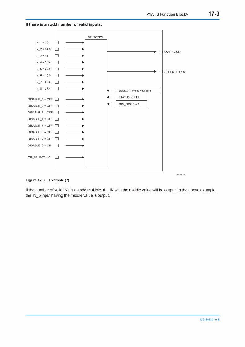
<17. IS Function Block> 17-9
IM 21B04C01-01E
If there is an odd number of valid inputs:
IN_1 = 23
SELECT_TYPE = Middle
STATUS_OPTS
MIN_GOOD = 1
SELECTION
SELECTED = 5
OUT = 23.6IN_2 = 34.5
IN_3 = 45
IN_4 = 2.34
IN_5 = 23.6
IN_6 = 15.5
IN_7 = 32.5
IN_8 = 27.4
DISABLE_1 = OFF
DISABLE_2 = OFF
DISABLE_3 = OFF
DISABLE_4 = OFF
DISABLE_5 = OFF
DISABLE_6 = OFF
DISABLE_7 = OFF
DISABLE_8 = ON
OP_SELECT = 0
F1708.ai
Figure 17.8 Example (7)
If the number of valid INs is an odd multiple, the IN with the middle value will be output. In the above example, the IN_5 input having the middle value is output.
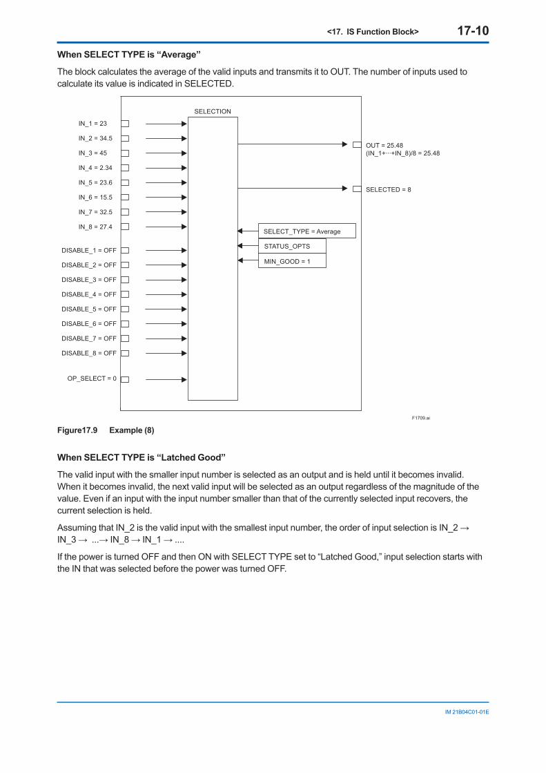
<17. IS Function Block> 17-10
IM 21B04C01-01E
When SELECT TYPE is “Average”
The block calculates the average of the valid inputs and transmits it to OUT. The number of inputs used to calculate its value is indicated in SELECTED.
SELECTION
IN_1 = 23
SELECT_TYPE = Average
STATUS_OPTS
MIN_GOOD = 1
SELECTED = 8
OUT = 25.48(IN_1+···+IN_8)/8 = 25.48
IN_2 = 34.5
IN_3 = 45
IN_4 = 2.34
IN_5 = 23.6
IN_6 = 15.5
IN_7 = 32.5
IN_8 = 27.4
DISABLE_1 = OFF
DISABLE_2 = OFF
DISABLE_3 = OFF
DISABLE_4 = OFF
DISABLE_5 = OFF
DISABLE_6 = OFF
DISABLE_7 = OFF
DISABLE_8 = OFF
OP_SELECT = 0
F1709.ai
Figure17.9 Example (8)
When SELECT TYPE is “Latched Good”
The valid input with the smaller input number is selected as an output and is held until it becomes invalid. When it becomes invalid, the next valid input will be selected as an output regardless of the magnitude of the value. Even if an input with the input number smaller than that of the currently selected input recovers, the current selection is held.
Assuming that IN_2 is the valid input with the smallest input number, the order of input selection is IN_2 → IN_3 → ...→ IN_8 → IN_1 → ....
If the power is turned OFF and then ON with SELECT TYPE set to “Latched Good,” input selection starts with the IN that was selected before the power was turned OFF.
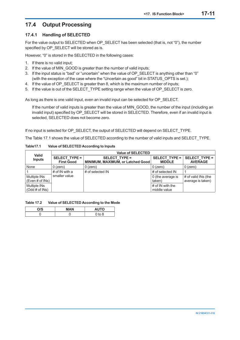
<17. IS Function Block> 17-11
IM 21B04C01-01E
17.4 Output Processing 17.4.1 Handling of SELECTED For the value output to SELECTED when OP_SELECT has been selected (that is, not “0”), the number specified by OP_SELECT will be stored as is.
However, “0” is stored in the SELECTED in the following cases:
1. If there is no valid input;2. If the value of MIN_GOOD is greater than the number of valid inputs;3. If the input status is “bad” or “uncertain” when the value of OP_SELECT is anything other than “0”
(with the exception of the case where the “Uncertain as good” bit in STATUS_OPTS is set.);4. If the value of OP_SELECT is greater than 8, which is the maximum number of inputs; 5. If the value is out of the SELECT_TYPE setting range when the value of OP_SELECT is zero.
As long as there is one valid input, even an invalid input can be selected for OP_SELECT.
If the number of valid inputs is greater than the value of MIN_GOOD, the number of the input (including an invalid input) specified by OP_SELECT will be stored in SELECTED. Therefore, even if an invalid input is selected, SELECTED does not become zero.
If no input is selected for OP_SELECT, the output of SELECTED will depend on SELECT_TYPE.
The Table 17.1 shows the value of SELECTED according to the number of valid inputs and SELECT_TYPE.
Table17.1 Value of SELECTED According to Inputs
Valid Inputs
Value of SELECTEDSELECT_TYPE =
First GoodSELECT_TYPE =
MINIMUM, MAXIMUM, or Latched GoodSELECT_TYPE =
MIDDLESELECT_TYPE =
AVERAGENone 0 (zero) 0 (zero) 0 (zero) 0 (zero)1 # of IN with a
smaller value# of selected IN # of selected IN 1
Multiple INs(Even # of INs)
0 (the average is taken)
# of valid INs (the average is taken)
Multiple INs(Odd # of INs)
# of IN with the middle value
Table 17.2 Value of SELECTED According to the Mode
O/S MAN AUTO0 0 0 to 8
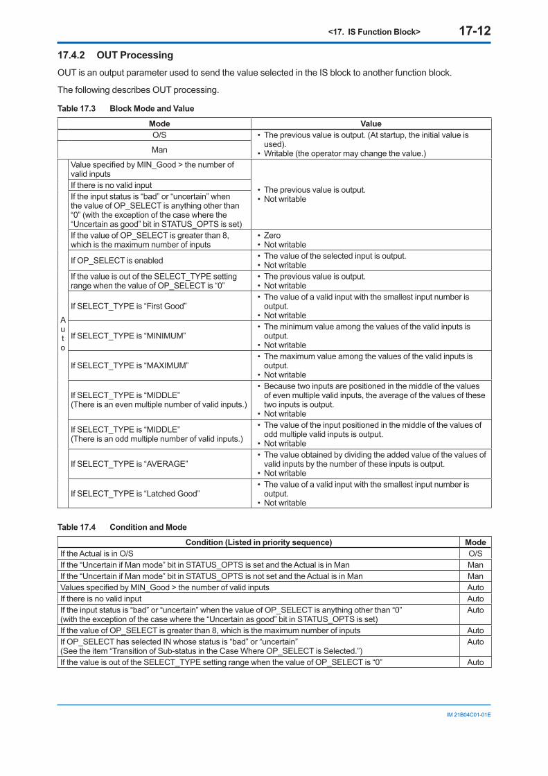
<17. IS Function Block> 17-12
IM 21B04C01-01E
17.4.2 OUT Processing OUT is an output parameter used to send the value selected in the IS block to another function block.
The following describes OUT processing.
Table 17.3 Block Mode and Value
Mode ValueO/S • The previous value is output. (At startup, the initial value is
used).• Writable (the operator may change the value.)Man
Auto
Value specified by MIN_Good > the number of valid inputs
• The previous value is output. • Not writable
If there is no valid inputIf the input status is “bad” or “uncertain” when the value of OP_SELECT is anything other than “0” (with the exception of the case where the “Uncertain as good” bit in STATUS_OPTS is set)If the value of OP_SELECT is greater than 8, which is the maximum number of inputs
• Zero • Not writable
If OP_SELECT is enabled • The value of the selected input is output.• Not writable
If the value is out of the SELECT_TYPE setting range when the value of OP_SELECT is “0”
• The previous value is output.• Not writable
If SELECT_TYPE is “First Good”• The value of a valid input with the smallest input number is
output.• Not writable
If SELECT_TYPE is “MINIMUM”• The minimum value among the values of the valid inputs is
output.• Not writable
If SELECT_TYPE is “MAXIMUM”• The maximum value among the values of the valid inputs is
output.• Not writable
If SELECT_TYPE is “MIDDLE”(There is an even multiple number of valid inputs.)
• Because two inputs are positioned in the middle of the values of even multiple valid inputs, the average of the values of these two inputs is output.
• Not writable
If SELECT_TYPE is “MIDDLE” (There is an odd multiple number of valid inputs.)
• The value of the input positioned in the middle of the values of odd multiple valid inputs is output.
• Not writable
If SELECT_TYPE is “AVERAGE”• The value obtained by dividing the added value of the values of
valid inputs by the number of these inputs is output.• Not writable
If SELECT_TYPE is “Latched Good”• The value of a valid input with the smallest input number is
output.• Not writable
Table 17.4 Condition and Mode
Condition (Listed in priority sequence) ModeIf the Actual is in O/S O/SIf the “Uncertain if Man mode” bit in STATUS_OPTS is set and the Actual is in Man ManIf the “Uncertain if Man mode” bit in STATUS_OPTS is not set and the Actual is in Man ManValues specified by MIN_Good > the number of valid inputs AutoIf there is no valid input AutoIf the input status is “bad” or “uncertain” when the value of OP_SELECT is anything other than “0”(with the exception of the case where the “Uncertain as good” bit in STATUS_OPTS is set)
Auto
If the value of OP_SELECT is greater than 8, which is the maximum number of inputs AutoIf OP_SELECT has selected IN whose status is “bad” or “uncertain”(See the item “Transition of Sub-status in the Case Where OP_SELECT is Selected.”)
Auto
If the value is out of the SELECT_TYPE setting range when the value of OP_SELECT is “0” Auto
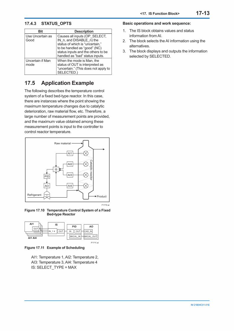
<17. IS Function Block> 17-13
IM 21B04C01-01E
17.4.3 STATUS_OPTS
Bit DescriptionUse Uncertain as Good
Causes all inputs (OP_SELECT, IN_n, and DISABLE_n) the status of which is “uncertain,” to be handled as “good” (NC) status inputs and the others to be handled as ”bad” status inputs.
Uncertain if Man mode
When the mode is Man, the status of OUT is interpreted as “uncertain.” (This does not apply to SELECTED.)
17.5 Application Example The following describes the temperature control system of a fixed bed-type reactor. In this case, there are instances where the point showing the maximum temperature changes due to catalytic deterioration, raw material flow, etc. Therefore, a large number of measurement points are provided, and the maximum value obtained among these measurement points is input to the controller to control reactor temperature.
F1710.ai
IS
PID AI3
AI1
AI2
AI4AO
Refrigerant
Raw material
Product
Catalytic reactor
Figure 17.10 Temperature Control System of a Fixed Bed-type Reactor
IS
IN_1 4 OUT
PID
BKCAL_IN
OUTIN
AO
CAS_IN
BKCAL_OUT
AI1
OUT
AI1
OUT
AI
OUT
AI1
OUT
AI1 AI4
F1711.ai
Figure 17.11 Example of Scheduling
AI1: Temperature 1, AI2: Temperature 2, AI3: Temperature 3, AI4: Temperature 4 IS: SELECT_TYPE = MAX
Basic operations and work sequence:
1. The IS block obtains values and status information from AI.
2. The block selects the AI information using the alternatives.
3. The block displays and outputs the information selected by SELECTED.
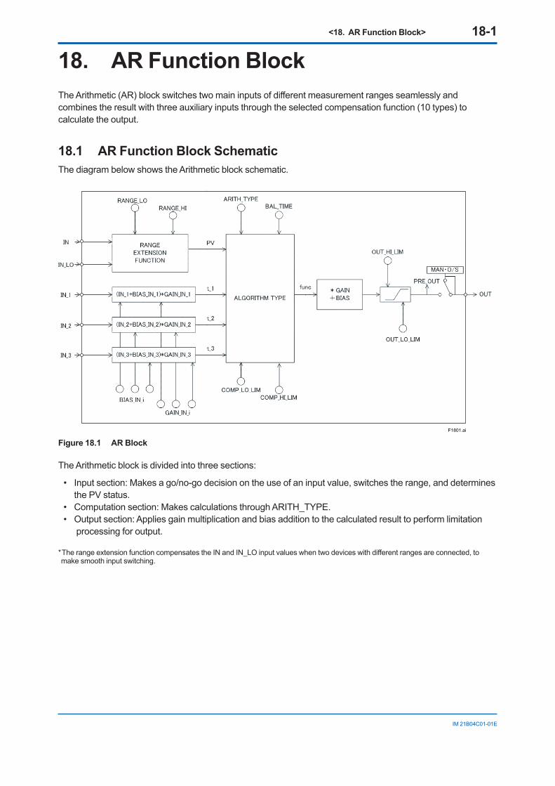
<18. AR Function Block> 18-1
IM 21B04C01-01E
18. AR Function BlockThe Arithmetic (AR) block switches two main inputs of different measurement ranges seamlessly and combines the result with three auxiliary inputs through the selected compensation function (10 types) to calculate the output.
18.1 AR Function Block SchematicThe diagram below shows the Arithmetic block schematic.
F1801.ai
Figure 18.1 AR Block
The Arithmetic block is divided into three sections:
• Input section: Makes a go/no-go decision on the use of an input value, switches the range, and determines the PV status.
• Computation section: Makes calculations through ARITH_TYPE. • Output section: Applies gain multiplication and bias addition to the calculated result to perform limitation
processing for output.
* The range extension function compensates the IN and IN_LO input values when two devices with different ranges are connected, to make smooth input switching.
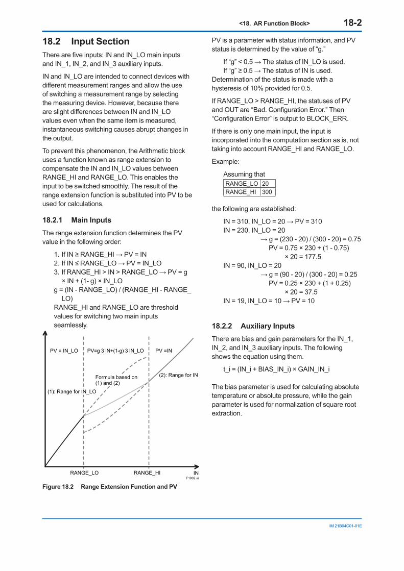
<18. AR Function Block> 18-2
IM 21B04C01-01E
18.2 Input Section There are five inputs: IN and IN_LO main inputs and IN_1, IN_2, and IN_3 auxiliary inputs.
IN and IN_LO are intended to connect devices with different measurement ranges and allow the use of switching a measurement range by selecting the measuring device. However, because there are slight differences between IN and IN_LO values even when the same item is measured, instantaneous switching causes abrupt changes in the output.
To prevent this phenomenon, the Arithmetic block uses a function known as range extension to compensate the IN and IN_LO values between RANGE_HI and RANGE_LO. This enables the input to be switched smoothly. The result of the range extension function is substituted into PV to be used for calculations.
18.2.1 Main Inputs The range extension function determines the PV value in the following order:
1. If IN ≥ RANGE_HI → PV = IN2. If IN ≤ RANGE_LO → PV = IN_LO 3. If RANGE_HI > IN > RANGE_LO → PV = g
× IN + (1- g) × IN_LO g = (IN - RANGE_LO) / (RANGE_HI - RANGE_
LO) RANGE_HI and RANGE_LO are threshold
values for switching two main inputs seamlessly.
F1802.aiRANGE_LO
PV = IN_LO PV=g 3 IN+(1-g) 3 IN_LO PV =IN
RANGE_HI IN
Formula based on (1) and (2)
(2): Range for IN
(1): Range for IN_LO
Figure 18.2 Range Extension Function and PV
PV is a parameter with status information, and PV status is determined by the value of “g.”
If “g” < 0.5 → The status of IN_LO is used. If “g” ≥ 0.5 → The status of IN is used.
Determination of the status is made with a hysteresis of 10% provided for 0.5.
If RANGE_LO > RANGE_HI, the statuses of PV and OUT are “Bad. Configuration Error.” Then “Configuration Error” is output to BLOCK_ERR.
If there is only one main input, the input is incorporated into the computation section as is, not taking into account RANGE_HI and RANGE_LO.
Example:
Assuming that RANGE_LO 20RANGE_HI 300
the following are established:
IN = 310, IN_LO = 20 → PV = 310IN = 230, IN_LO = 20 → g = (230 - 20) / (300 - 20) = 0.75 PV = 0.75 × 230 + (1 - 0.75)
× 20 = 177.5IN = 90, IN_LO = 20 → g = (90 - 20) / (300 - 20) = 0.25 PV = 0.25 × 230 + (1 + 0.25)
× 20 = 37.5IN = 19, IN_LO = 10 → PV = 10
18.2.2 Auxiliary Inputs There are bias and gain parameters for the IN_1, IN_2, and IN_3 auxiliary inputs. The following shows the equation using them.
t_i = (IN_i + BIAS_IN_i) × GAIN_IN_i
The bias parameter is used for calculating absolute temperature or absolute pressure, while the gain parameter is used for normalization of square root extraction.
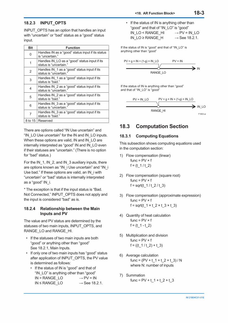
<18. AR Function Block> 18-3
IM 21B04C01-01E
18.2.3 INPUT_OPTS INPUT_OPTS has an option that handles an input with “uncertain” or “bad” status as a “good” status input.
Bit Function
0 Handles IN as a “good” status input if its status is “uncertain.”
1 Handles IN_LO as a “good” status input if its status is “uncertain.”
2 Handles IN_1 as a “good” status input if its status is “uncertain.”
3 Handles IN_1 as a “good” status input if its status is “bad.”
4 Handles IN_2 as a “good” status input if its status is “uncertain.”
5 Handles IN_2 as a “good” status input if its status is “bad.”
6 Handles IN_3 as a “good” status input if its status is “uncertain.”
7 Handles IN_3 as a “good” status input if its status is “bad.”
8 to 15 Reserved
There are options called “IN Use uncertain” and “IN_LO Use uncertain” for the IN and IN_LO inputs. When these options are valid, IN and IN_LO are internally interpreted as “good” IN and IN_LO even if their statuses are “uncertain.” (There is no option for “bad” status.)
For the IN_1, IN_2, and IN_3 auxiliary inputs, there are options known as “IN_i Use uncertain” and “IN_i Use bad.” If these options are valid, an IN_i with “uncertain” or “bad” status is internally interpreted as a “good” IN_i.
* The exception is that if the input status is “Bad. Not Connected,” INPUT_OPTS does not apply and the input is considered “bad” as is.
18.2.4 Relationship between the Main Inputs and PV
The value and PV status are determined by the statuses of two main inputs, INPUT_OPTS, and RANGE_LO and RANGE_HI.
• If the statuses of two main inputs are both “good” or anything other than “good”
See 18.2.1, Main Inputs. • If only one of two main inputs has “good” status
after application of INPUT_OPTS, the PV value is determined as follows: • If the status of IN is “good” and that of
“IN_LO” is anything other than “good” IN > RANGE_LO → PV = IN IN ≤ RANGE_LO → See 18.2.1.
• If the status of IN is anything other than “good” and that of “IN_LO” is “good”
IN_LO < RANGE_HI → PV = IN_LO IN_LO ≥ RANGE_H → See 18.2.1.
RANGE_LO
RANGE_HI
PV = IN_LO
PV = IN
PV = g × IN + (1-g) × IN_LO
PV = g × IN + (1-g) × IN_LO
IN
IN_LO
F1803.ai
If the status of IN is “good” and that of “IN_LO” is anything other than “good”
If the status of IN is anything other than “good” and that of “IN_LO” is “good”
18.3 Computation Section 18.3.1 Computing Equations This subsection shows computing equations used in the computation section:
1) Flow compensation (linear) func = PV × f f = (t_1 / t_2)
2) Flow compensation (square root) func = PV × f f = sqrt(t_1 / t_2 / t_3)
3) Flow compensation (approximate expression) func = PV × f f = sqrt(t_1 × t_2 × t_3 × t_3)
4) Quantity of heat calculation func = PV × f f = (t_1 - t_2)
5) Multiplication and division func = PV × f f = ((t_1 / t_2) + t_3)
6) Average calculation func = (PV + t_1 + t_2 + t_3) / N where N: number of inputs
7) Summation func = PV + t_1 + t_2 + t_3
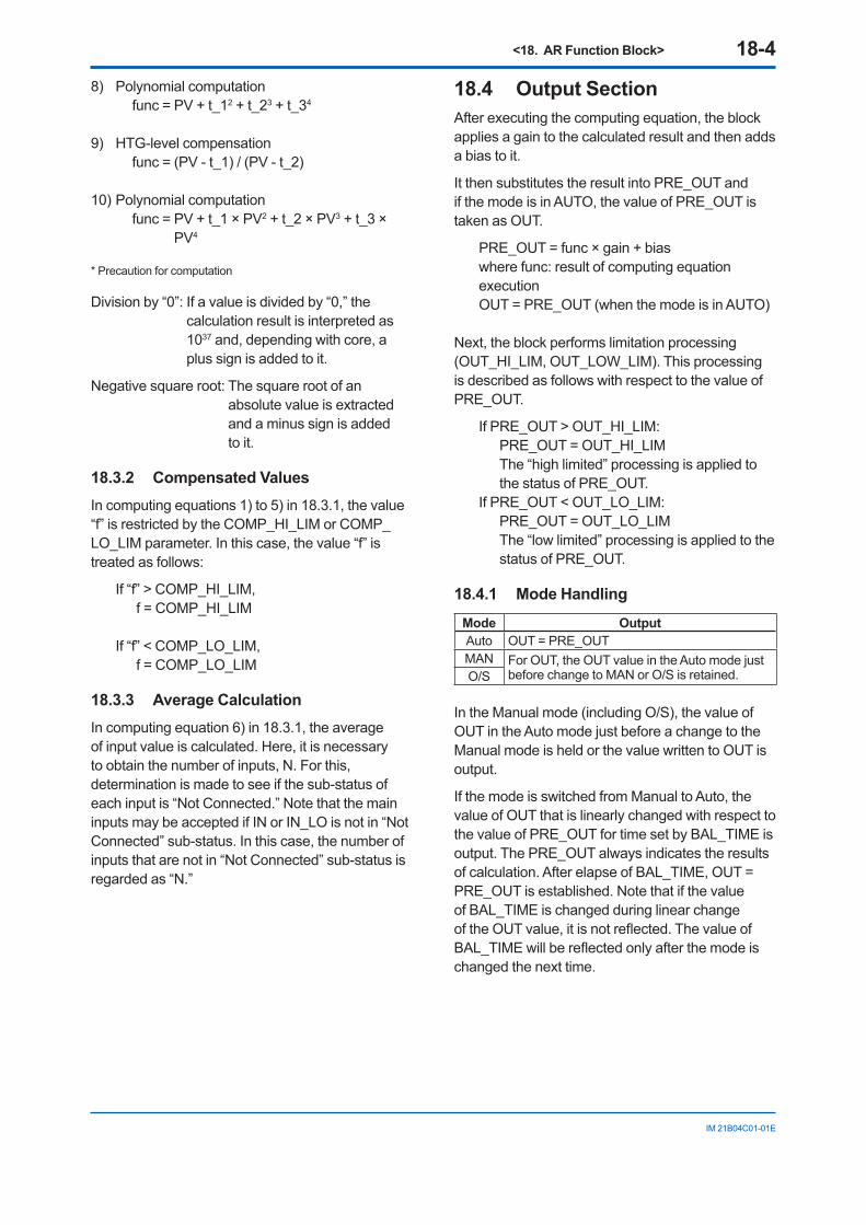
<18. AR Function Block> 18-4
IM 21B04C01-01E
8) Polynomial computation func = PV + t_12 + t_23 + t_34
9) HTG-level compensation func = (PV - t_1) / (PV - t_2)
10) Polynomial computation
func = PV + t_1 × PV2 + t_2 × PV3 + t_3 × PV4
* Precaution for computation
Division by “0”: If a value is divided by “0,” the calculation result is interpreted as 1037 and, depending with core, a plus sign is added to it.
Negative square root: The square root of an absolute value is extracted and a minus sign is added to it.
18.3.2 Compensated Values In computing equations 1) to 5) in 18.3.1, the value “f” is restricted by the COMP_HI_LIM or COMP_LO_LIM parameter. In this case, the value “f” is treated as follows:
If “f” > COMP_HI_LIM, f = COMP_HI_LIM
If “f” < COMP_LO_LIM, f = COMP_LO_LIM
18.3.3 Average Calculation In computing equation 6) in 18.3.1, the average of input value is calculated. Here, it is necessary to obtain the number of inputs, N. For this, determination is made to see if the sub-status of each input is “Not Connected.” Note that the main inputs may be accepted if IN or IN_LO is not in “Not Connected” sub-status. In this case, the number of inputs that are not in “Not Connected” sub-status is regarded as “N.”
18.4 Output Section After executing the computing equation, the block applies a gain to the calculated result and then adds a bias to it.
It then substitutes the result into PRE_OUT and if the mode is in AUTO, the value of PRE_OUT is taken as OUT.
PRE_OUT = func × gain + bias where func: result of computing equation executionOUT = PRE_OUT (when the mode is in AUTO)
Next, the block performs limitation processing (OUT_HI_LIM, OUT_LOW_LIM). This processing is described as follows with respect to the value of PRE_OUT.
If PRE_OUT > OUT_HI_LIM: PRE_OUT = OUT_HI_LIM The “high limited” processing is applied to
the status of PRE_OUT. If PRE_OUT < OUT_LO_LIM: PRE_OUT = OUT_LO_LIM The “low limited” processing is applied to the
status of PRE_OUT.
18.4.1 Mode Handling
Mode OutputAuto OUT = PRE_OUTMAN For OUT, the OUT value in the Auto mode just
before change to MAN or O/S is retained.O/S
In the Manual mode (including O/S), the value of OUT in the Auto mode just before a change to the Manual mode is held or the value written to OUT is output.
If the mode is switched from Manual to Auto, the value of OUT that is linearly changed with respect to the value of PRE_OUT for time set by BAL_TIME is output. The PRE_OUT always indicates the results of calculation. After elapse of BAL_TIME, OUT = PRE_OUT is established. Note that if the value of BAL_TIME is changed during linear change of the OUT value, it is not reflected. The value of BAL_TIME will be reflected only after the mode is changed the next time.
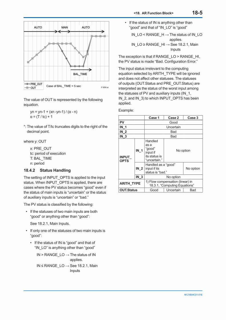
<18. AR Function Block> 18-5
IM 21B04C01-01E
F1804.aiPRE_OUTOUT
AUTO MAN AUTO
BAL_TIME
Case of BAL_TIME = 5 sec
The value of OUT is represented by the following equation.
yn = yn-1 + (xn -yn-1) / (α - n) α = (T / tc) + 1
*: The value of T/tc truncates digits to the right of the decimal point.
where y: OUT
x: PRE_OUTtc: period of execution T: BAL_TIME n: period
18.4.2 Status Handling The setting of INPUT_OPTS is applied to the input status. When INPUT_OPTS is applied, there are cases where the PV status becomes “good” even if the status of main inputs is “uncertain” or the status of auxiliary inputs is “uncertain” or “bad.”
The PV status is classified by the following:
• If the statuses of two main inputs are both “good” or anything other than “good”:
See 18.2.1, Main Inputs.
• If only one of the statuses of two main inputs is “good”:
• If the status of IN is “good” and that of “IN_LO” is anything other than “good”
IN > RANGE_LO → The status of IN applies.
IN ≤ RANGE_LO → See 18.2.1, Main Inputs
• If the status of IN is anything other than “good” and that of “IN_LO” is “good”
IN_LO < RANGE_H → The status of IN_LO applies.
IN_LO ≥ RANGE_HI → See 18.2.1, Main Inputs
The exception is that if RANGE_LO > RANGE_HI, the PV status is made “Bad. Configuration Error.”
The input status irrelevant to the computing equation selected by ARITH_TYPE will be ignored and does not affect other statuses. The statuses of outputs (OUT.Status and PRE_OUT.Status) are interpreted as the status of the worst input among the statuses of PV and auxiliary inputs (IN_1, IN_2, and IN_3) to which INPUT_OPTS has been applied.
Example:
Case 1 Case 2 Case 3PV GoodIN_1 UncertainIN_2 BadIN_3 Bad
INPUT_OPTS
IN_1
Handled as a“good” input ifits status is “uncertain.”
No option
IN_2Handled as a “good” input if itsstatus is “bad.”
No option
IN_3 No option
ARITH_TYPE 1) Flow compensation (linear) in 18.3.1, “Computing Equations”
OUT.Status Good Uncertain Bad
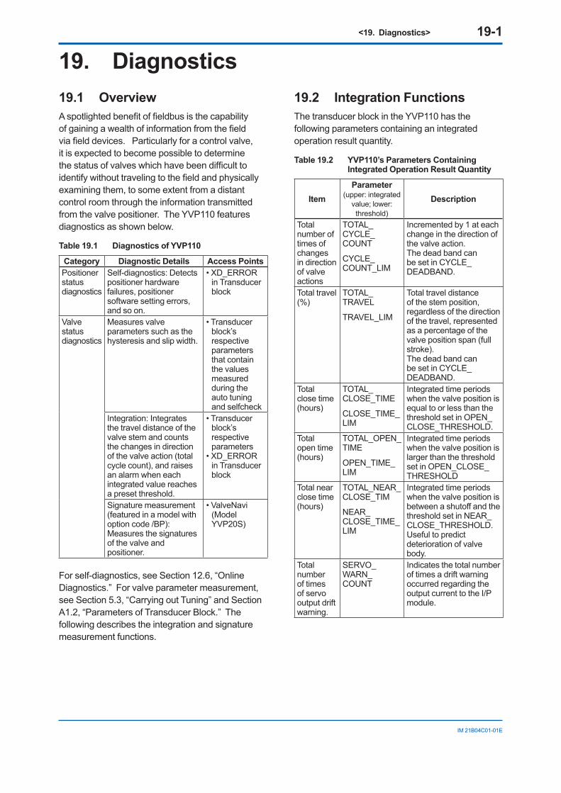
<19. Diagnostics> 19-1
IM 21B04C01-01E
19. Diagnostics19.1 OverviewA spotlighted benefit of fieldbus is the capability of gaining a wealth of information from the field via field devices. Particularly for a control valve, it is expected to become possible to determine the status of valves which have been difficult to identify without traveling to the field and physically examining them, to some extent from a distant control room through the information transmitted from the valve positioner. The YVP110 features diagnostics as shown below.
Table 19.1 Diagnostics of YVP110
Category Diagnostic Details Access PointsPositioner status diagnostics
Self-diagnostics: Detects positioner hardware failures, positioner software setting errors, and so on.
• XD_ERROR in Transducer block
Valve status diagnostics
Measures valve parameters such as the hysteresis and slip width.
• Transducer block’s respective parameters that contain the values measured during the auto tuning and selfcheck
Integration: Integrates the travel distance of the valve stem and counts the changes in direction of the valve action (total cycle count), and raises an alarm when each integrated value reaches a preset threshold.
• Transducer block’s respective parameters
• XD_ERROR in Transducer block
Signature measurement (featured in a model with option code /BP):Measures the signatures of the valve and positioner.
• ValveNavi (Model YVP20S)
For self-diagnostics, see Section 12.6, “Online Diagnostics.” For valve parameter measurement, see Section 5.3, “Carrying out Tuning” and Section A1.2, “Parameters of Transducer Block.” The following describes the integration and signature measurement functions.
19.2 Integration FunctionsThe transducer block in the YVP110 has the following parameters containing an integrated operation result quantity.
Table 19.2 YVP110’s Parameters Containing Integrated Operation Result Quantity
ItemParameter
(upper: integrated value; lower: threshold)
Description
Total number of times of changes in direction of valve actions
TOTAL_CYCLE_COUNT
CYCLE_COUNT_LIM
Incremented by 1 at each change in the direction of the valve action. The dead band can be set in CYCLE_DEADBAND.
Total travel (%)
TOTAL_TRAVEL
TRAVEL_LIM
Total travel distance of the stem position, regardless of the direction of the travel, represented as a percentage of the valve position span (full stroke).The dead band can be set in CYCLE_DEADBAND.
Total close time (hours)
TOTAL_CLOSE_TIME
CLOSE_TIME_LIM
Integrated time periods when the valve position is equal to or less than the threshold set in OPEN_CLOSE_THRESHOLD.
Total open time (hours)
TOTAL_OPEN_TIME
OPEN_TIME_LIM
Integrated time periods when the valve position is larger than the threshold set in OPEN_CLOSE_THRESHOLD
Total near close time (hours)
TOTAL_NEAR_CLOSE_TIM
NEAR_CLOSE_TIME_LIM
Integrated time periods when the valve position is between a shutoff and the threshold set in NEAR_CLOSE_THRESHOLD.Useful to predict deterioration of valve body.
Total number of times of servo output drift warning.
SERVO_WARN_COUNT
Indicates the total number of times a drift warning occurred regarding the output current to the I/P module.
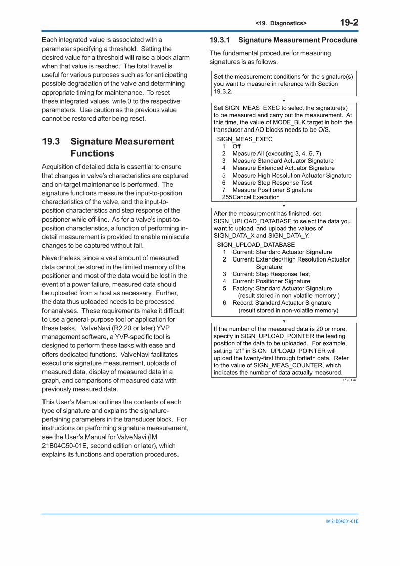
<19. Diagnostics> 19-2
IM 21B04C01-01E
Each integrated value is associated with a parameter specifying a threshold. Setting the desired value for a threshold will raise a block alarm when that value is reached. The total travel is useful for various purposes such as for anticipating possible degradation of the valve and determining appropriate timing for maintenance. To reset these integrated values, write 0 to the respective parameters. Use caution as the previous value cannot be restored after being reset.
19.3 Signature Measurement Functions
Acquisition of detailed data is essential to ensure that changes in valve’s characteristics are captured and on-target maintenance is performed. The signature functions measure the input-to-position characteristics of the valve, and the input-to-position characteristics and step response of the positioner while off-line. As for a valve’s input-to-position characteristics, a function of performing in-detail measurement is provided to enable miniscule changes to be captured without fail.
Nevertheless, since a vast amount of measured data cannot be stored in the limited memory of the positioner and most of the data would be lost in the event of a power failure, measured data should be uploaded from a host as necessary. Further, the data thus uploaded needs to be processed for analyses. These requirements make it difficult to use a general-purpose tool or application for these tasks. ValveNavi (R2.20 or later) YVP management software, a YVP-specific tool is designed to perform these tasks with ease and offers dedicated functions. ValveNavi facilitates executions signature measurement, uploads of measured data, display of measured data in a graph, and comparisons of measured data with previously measured data.
This User’s Manual outlines the contents of each type of signature and explains the signature-pertaining parameters in the transducer block. For instructions on performing signature measurement, see the User’s Manual for ValveNavi (IM 21B04C50-01E, second edition or later), which explains its functions and operation procedures.
19.3.1 Signature Measurement ProcedureThe fundamental procedure for measuring signatures is as follows.
F1901.ai
After the measurement has finished, set SIGN_UPLOAD_DATABASE to select the data you want to upload, and upload the values of SIGN_DATA_X and SIGN_DATA_Y. SIGN_UPLOAD_DATABASE
1 Current: Standard Actuator Signature 2 Current: Extended/High Resolution Actuator
Signature3 Current: Step Response Test4 Current: Positioner Signature5 Factory: Standard Actuator Signature (result stored in non-volatile memory )6 Record: Standard Actuator Signature (result stored in non-volatile memory)
Set SIGN_MEAS_EXEC to select the signature(s) to be measured and carry out the measurement. At this time, the value of MODE_BLK target in both the transducer and AO blocks needs to be O/S. SIGN_MEAS_EXEC
1 Off 2 Measure All (executing 3, 4, 6, 7)3 Measure Standard Actuator Signature 4 Measure Extended Actuator Signature5 Measure High Resolution Actuator Signature6 Measure Step Response Test7 Measure Positioner Signature255 Cancel Execution
Set the measurement conditions for the signature(s) you want to measure in reference with Section 19.3.2.
If the number of the measured data is 20 or more, specify in SIGN_UPLOAD_POINTER the leading position of the data to be uploaded. For example, setting “21” in SIGN_UPLOAD_POINTER will upload the twenty-first through fortieth data. Refer to the value of SIGN_MEAS_COUNTER, which indicates the number of data actually measured.
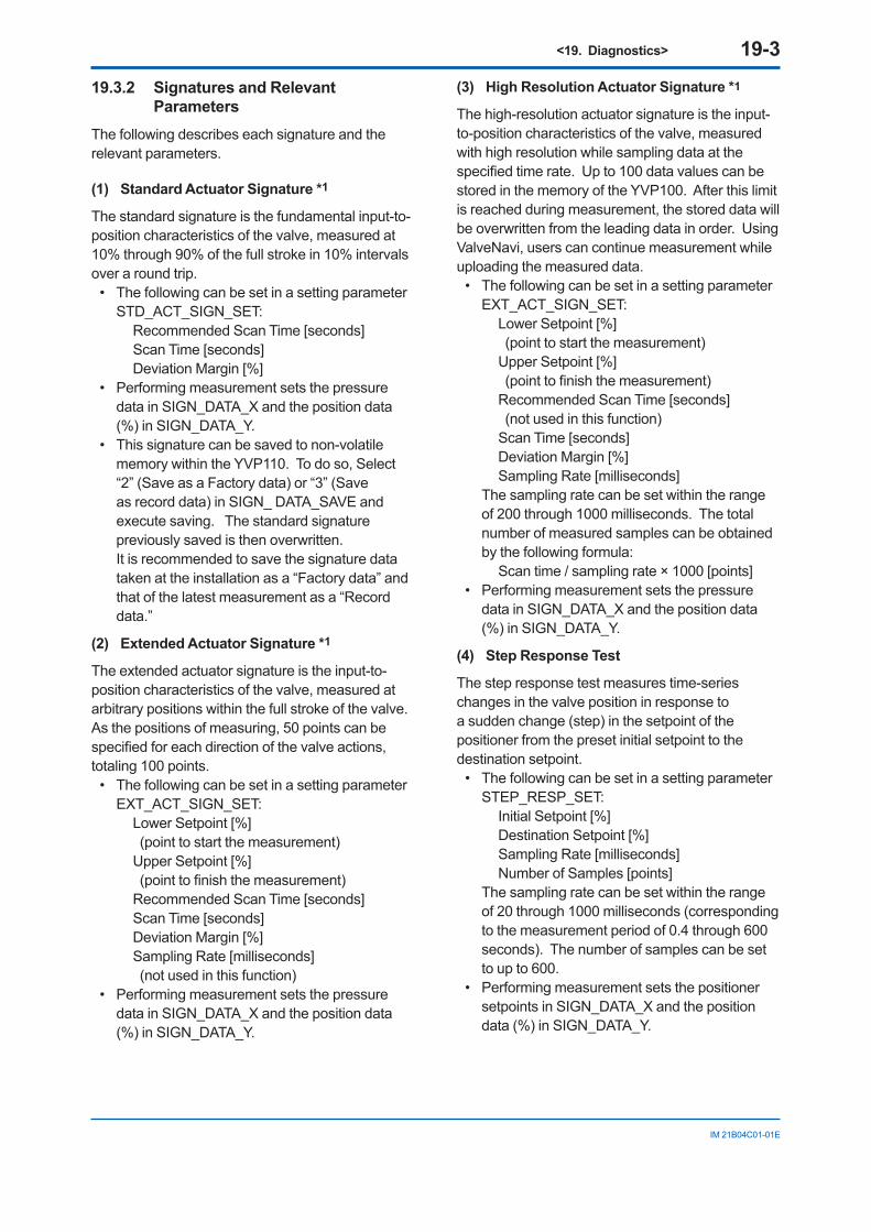
<19. Diagnostics> 19-3
IM 21B04C01-01E
19.3.2 Signatures and Relevant Parameters
The following describes each signature and the relevant parameters.
(1) Standard Actuator Signature *1
The standard signature is the fundamental input-to-position characteristics of the valve, measured at 10% through 90% of the full stroke in 10% intervals over a round trip.
• The following can be set in a setting parameter STD_ACT_SIGN_SET: Recommended Scan Time [seconds] Scan Time [seconds] Deviation Margin [%]
• Performing measurement sets the pressure data in SIGN_DATA_X and the position data (%) in SIGN_DATA_Y.
• This signature can be saved to non-volatile memory within the YVP110. To do so, Select “2” (Save as a Factory data) or “3” (Save as record data) in SIGN_ DATA_SAVE and execute saving. The standard signature previously saved is then overwritten.
It is recommended to save the signature data taken at the installation as a “Factory data” and that of the latest measurement as a “Record data.”
(2) Extended Actuator Signature *1
The extended actuator signature is the input-to-position characteristics of the valve, measured at arbitrary positions within the full stroke of the valve. As the positions of measuring, 50 points can be specified for each direction of the valve actions, totaling 100 points.
• The following can be set in a setting parameter EXT_ACT_SIGN_SET: Lower Setpoint [%]
(point to start the measurement) Upper Setpoint [%]
(point to finish the measurement) Recommended Scan Time [seconds] Scan Time [seconds] Deviation Margin [%] Sampling Rate [milliseconds]
(not used in this function) • Performing measurement sets the pressure
data in SIGN_DATA_X and the position data (%) in SIGN_DATA_Y.
(3) High Resolution Actuator Signature *1
The high-resolution actuator signature is the input-to-position characteristics of the valve, measured with high resolution while sampling data at the specified time rate. Up to 100 data values can be stored in the memory of the YVP100. After this limit is reached during measurement, the stored data will be overwritten from the leading data in order. Using ValveNavi, users can continue measurement while uploading the measured data.
• The following can be set in a setting parameter EXT_ACT_SIGN_SET: Lower Setpoint [%]
(point to start the measurement) Upper Setpoint [%]
(point to finish the measurement) Recommended Scan Time [seconds]
(not used in this function) Scan Time [seconds] Deviation Margin [%] Sampling Rate [milliseconds]
The sampling rate can be set within the range of 200 through 1000 milliseconds. The total number of measured samples can be obtained by the following formula: Scan time / sampling rate × 1000 [points]
• Performing measurement sets the pressure data in SIGN_DATA_X and the position data (%) in SIGN_DATA_Y.
(4) Step Response Test
The step response test measures time-series changes in the valve position in response to a sudden change (step) in the setpoint of the positioner from the preset initial setpoint to the destination setpoint.
• The following can be set in a setting parameter STEP_RESP_SET: Initial Setpoint [%] Destination Setpoint [%] Sampling Rate [milliseconds] Number of Samples [points]
The sampling rate can be set within the range of 20 through 1000 milliseconds (corresponding to the measurement period of 0.4 through 600 seconds). The number of samples can be set to up to 600.
• Performing measurement sets the positioner setpoints in SIGN_DATA_X and the position data (%) in SIGN_DATA_Y.
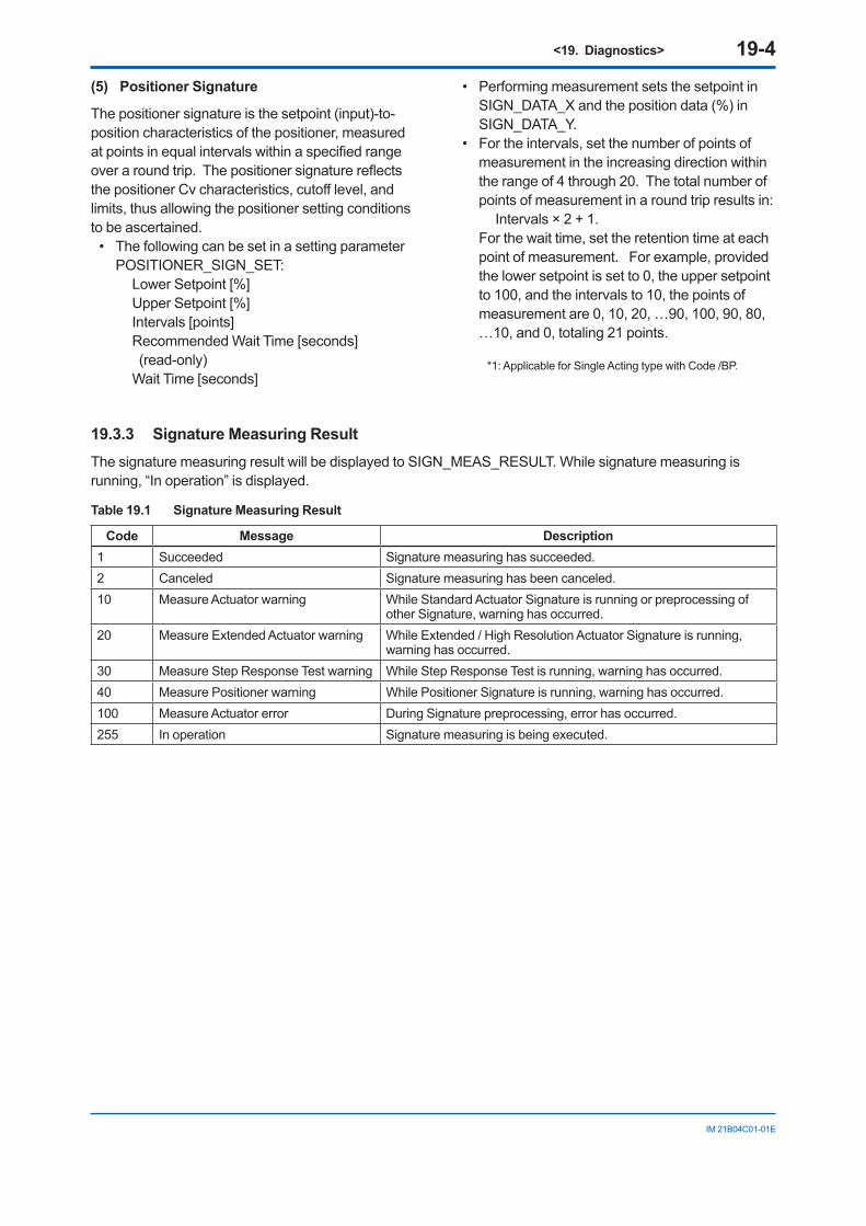
<19. Diagnostics> 19-4
IM 21B04C01-01E
(5) Positioner Signature
The positioner signature is the setpoint (input)-to-position characteristics of the positioner, measured at points in equal intervals within a specified range over a round trip. The positioner signature reflects the positioner Cv characteristics, cutoff level, and limits, thus allowing the positioner setting conditions to be ascertained.
• The following can be set in a setting parameter POSITIONER_SIGN_SET: Lower Setpoint [%] Upper Setpoint [%] Intervals [points] Recommended Wait Time [seconds]
(read-only) Wait Time [seconds]
• Performing measurement sets the setpoint in SIGN_DATA_X and the position data (%) in SIGN_DATA_Y.
• For the intervals, set the number of points of measurement in the increasing direction within the range of 4 through 20. The total number of points of measurement in a round trip results in: Intervals × 2 + 1.
For the wait time, set the retention time at each point of measurement. For example, provided the lower setpoint is set to 0, the upper setpoint to 100, and the intervals to 10, the points of measurement are 0, 10, 20, …90, 100, 90, 80, …10, and 0, totaling 21 points.
*1: Applicable for Single Acting type with Code /BP.
19.3.3 Signature Measuring ResultThe signature measuring result will be displayed to SIGN_MEAS_RESULT. While signature measuring is running, “In operation” is displayed.
Table 19.1 Signature Measuring Result
Code Message Description1 Succeeded Signature measuring has succeeded.2 Canceled Signature measuring has been canceled.10 Measure Actuator warning While Standard Actuator Signature is running or preprocessing of
other Signature, warning has occurred.20 Measure Extended Actuator warning While Extended / High Resolution Actuator Signature is running,
warning has occurred.30 Measure Step Response Test warning While Step Response Test is running, warning has occurred.40 Measure Positioner warning While Positioner Signature is running, warning has occurred.100 Measure Actuator error During Signature preprocessing, error has occurred.255 In operation Signature measuring is being executed.
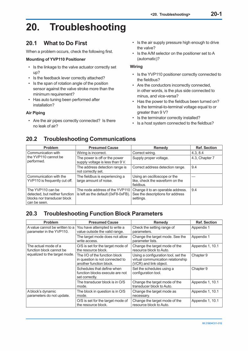
<20. Troubleshooting> 20-1
IM 21B04C01-01E
20. Troubleshooting20.1 What to Do FirstWhen a problem occurs, check the following first.
Mounting of YVP110 Positioner
• Is the linkage to the valve actuator correctly set up?
• Is the feedback lever correctly attached? • Is the span of rotation angle of the position
sensor against the valve stroke more than the minimum requirement?
• Has auto tuning been performed after installation?
Air Piping
• Are the air pipes correctly connected? Is there no leak of air?
• Is the air supply pressure high enough to drive the valve?
• Is the A/M selector on the positioner set to A (automatic)?
Wiring
• Is the YVP110 positioner correctly connected to the fieldbus?
• Are the conductors incorrectly connected, in other words, is the plus side connected to minus, and vice-versa?
• Has the power to the fieldbus been turned on? Is the terminal-to-terminal voltage equal to or greater than 9 V?
• Is the terminator correctly installed? • Is a host system connected to the fieldbus?
20.2 Troubleshooting CommunicationsProblem Presumed Cause Remedy Ref. Section
Communication with the YVP110 cannot be performed.
Wiring is incorrect. Correct wiring. 4.3, 8.4The power is off or the power supply voltage is less than 9 V.
Supply proper voltage. 4.3, Chapter 7
The address detection range is not correctly set.
Correct address detection range. 9.4
Communication with the YVP110 is frequently cut off.
The fieldbus is experiencing a large amount of noise.
Using an oscilloscope or the like, check the waveform on the fieldbus.
—
The YVP110 can be detected, but neither function blocks nor transducer block can be seen.
The node address of the YVP110 is left as the default (0xF8-0xFB).
Change it to an operable address. See the descriptions for address settings.
9.4
20.3 Troubleshooting Function Block ParametersProblem Presumed Cause Remedy Ref. Section
A value cannot be written to a parameter in the YVP110.
You have attempted to write a value outside the valid range.
Check the setting range of parameters.
Appendix 1
The target mode does not allow write access.
Change the target mode. See the parameter lists.
Appendix 1
The actual mode of a function block cannot be equalized to the target mode.
O/S is set for the target mode of the resource block.
Change the target mode of the resource block to Auto.
Appendix 1, 10.1
The I/O of the function block in question is not connected to another function block.
Using a configuration tool, set the virtual communication relationship (VCR) and link object.
Chapter 9
Schedules that define when function blocks execute are not set correctly.
Set the schedules using a configuration tool.
Chapter 9
The transducer block is in O/S mode.
Change the target mode of the transducer block to Auto.
Appendix 1, 10.1
A block’s dynamic parameters do not update.
The block in question is in O/S mode.
Change the target mode as necessary.
Appendix 1, 10.1
O/S is set for the target mode of the resource block.
Change the target mode of the resource block to Auto.
Appendix 1, 10.1
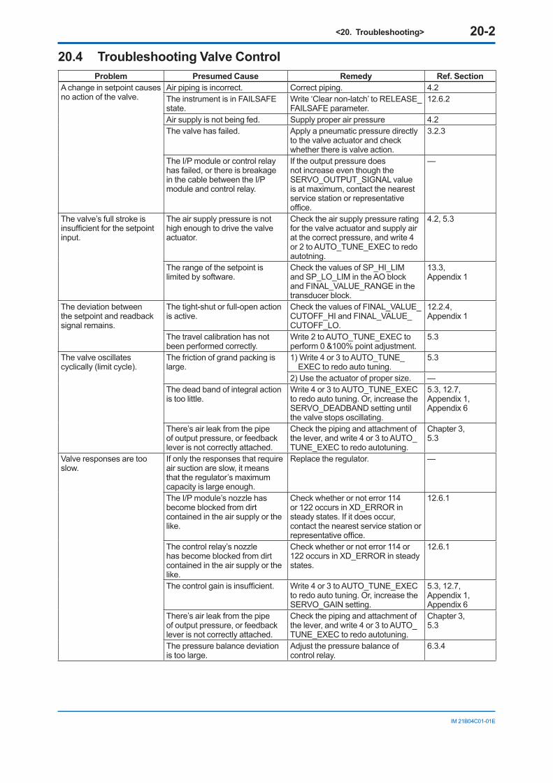
<20. Troubleshooting> 20-2
IM 21B04C01-01E
20.4 Troubleshooting Valve ControlProblem Presumed Cause Remedy Ref. Section
A change in setpoint causes no action of the valve.
Air piping is incorrect. Correct piping. 4.2The instrument is in FAILSAFE state.
Write ‘Clear non-latch’ to RELEASE_FAILSAFE parameter.
12.6.2
Air supply is not being fed. Supply proper air pressure 4.2The valve has failed. Apply a pneumatic pressure directly
to the valve actuator and check whether there is valve action.
3.2.3
The I/P module or control relay has failed, or there is breakage in the cable between the I/P module and control relay.
If the output pressure does not increase even though the SERVO_OUTPUT_SIGNAL value is at maximum, contact the nearest service station or representative office.
—
The valve’s full stroke is insufficient for the setpoint input.
The air supply pressure is not high enough to drive the valve actuator.
Check the air supply pressure rating for the valve actuator and supply air at the correct pressure, and write 4 or 2 to AUTO_TUNE_EXEC to redo autotning.
4.2, 5.3
The range of the setpoint is limited by software.
Check the values of SP_HI_LIM and SP_LO_LIM in the AO block and FINAL_VALUE_RANGE in the transducer block.
13.3, Appendix 1
The deviation between the setpoint and readback signal remains.
The tight-shut or full-open action is active.
Check the values of FINAL_VALUE_CUTOFF_HI and FINAL_VALUE_CUTOFF_LO.
12.2.4, Appendix 1
The travel calibration has not been performed correctly.
Write 2 to AUTO_TUNE_EXEC to perform 0 &100% point adjustment.
5.3
The valve oscillates cyclically (limit cycle).
The friction of grand packing is large.
1) Write 4 or 3 to AUTO_TUNE_EXEC to redo auto tuning.
5.3
2) Use the actuator of proper size. —The dead band of integral action is too little.
Write 4 or 3 to AUTO_TUNE_EXEC to redo auto tuning. Or, increase the SERVO_DEADBAND setting until the valve stops oscillating.
5.3, 12.7, Appendix 1, Appendix 6
There’s air leak from the pipe of output pressure, or feedback lever is not correctly attached.
Check the piping and attachment of the lever, and write 4 or 3 to AUTO_TUNE_EXEC to redo autotuning.
Chapter 3, 5.3
Valve responses are too slow.
If only the responses that require air suction are slow, it means that the regulator’s maximum capacity is large enough.
Replace the regulator. —
The I/P module’s nozzle has become blocked from dirt contained in the air supply or the like.
Check whether or not error 114 or 122 occurs in XD_ERROR in steady states. If it does occur, contact the nearest service station or representative office.
12.6.1
The control relay’s nozzle has become blocked from dirt contained in the air supply or the like.
Check whether or not error 114 or 122 occurs in XD_ERROR in steady states.
12.6.1
The control gain is insufficient. Write 4 or 3 to AUTO_TUNE_EXEC to redo auto tuning. Or, increase the SERVO_GAIN setting.
5.3, 12.7, Appendix 1, Appendix 6
There’s air leak from the pipe of output pressure, or feedback lever is not correctly attached.
Check the piping and attachment of the lever, and write 4 or 3 to AUTO_TUNE_EXEC to redo autotuning.
Chapter 3,5.3
The pressure balance deviation is too large.
Adjust the pressure balance of control relay.
6.3.4
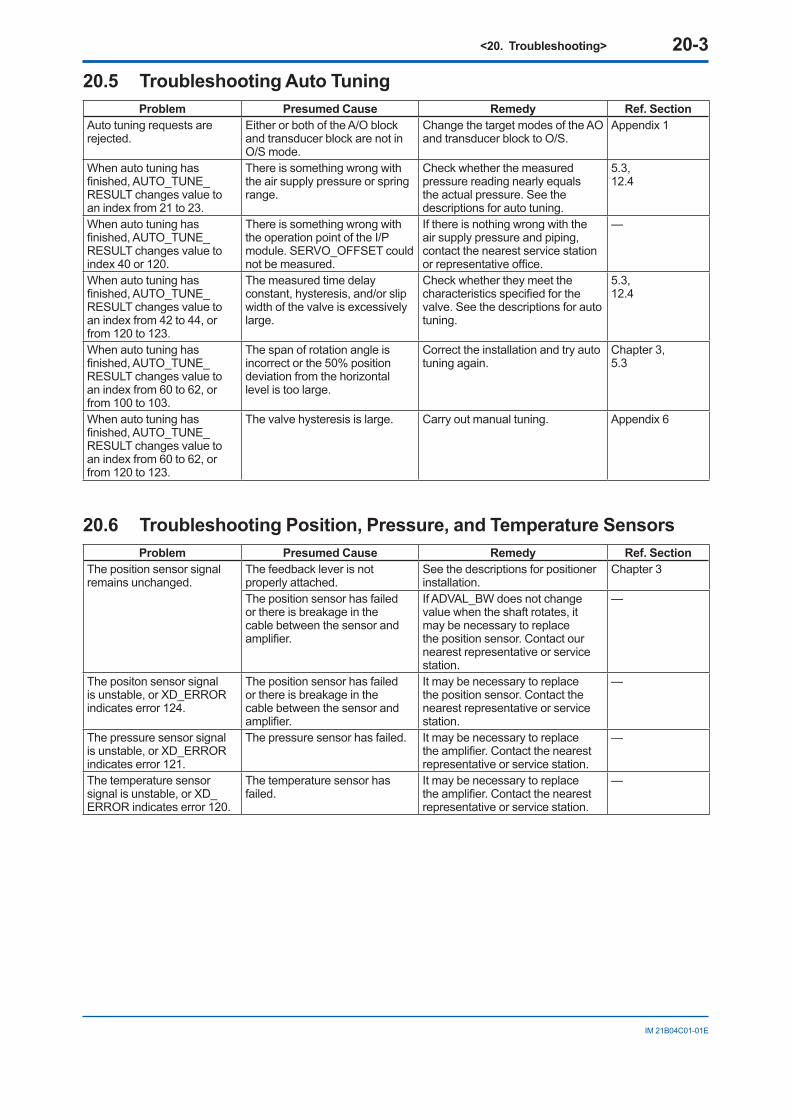
<20. Troubleshooting> 20-3
IM 21B04C01-01E
20.5 Troubleshooting Auto TuningProblem Presumed Cause Remedy Ref. Section
Auto tuning requests are rejected.
Either or both of the A/O block and transducer block are not in O/S mode.
Change the target modes of the AO and transducer block to O/S.
Appendix 1
When auto tuning has finished, AUTO_TUNE_RESULT changes value to an index from 21 to 23.
There is something wrong with the air supply pressure or spring range.
Check whether the measured pressure reading nearly equals the actual pressure. See the descriptions for auto tuning.
5.3, 12.4
When auto tuning has finished, AUTO_TUNE_RESULT changes value to index 40 or 120.
There is something wrong with the operation point of the I/P module. SERVO_OFFSET could not be measured.
If there is nothing wrong with the air supply pressure and piping, contact the nearest service station or representative office.
—
When auto tuning has finished, AUTO_TUNE_RESULT changes value to an index from 42 to 44, or from 120 to 123.
The measured time delay constant, hysteresis, and/or slip width of the valve is excessively large.
Check whether they meet the characteristics specified for the valve. See the descriptions for auto tuning.
5.3, 12.4
When auto tuning has finished, AUTO_TUNE_RESULT changes value to an index from 60 to 62, or from 100 to 103.
The span of rotation angle is incorrect or the 50% position deviation from the horizontal level is too large.
Correct the installation and try auto tuning again.
Chapter 3, 5.3
When auto tuning has finished, AUTO_TUNE_RESULT changes value to an index from 60 to 62, or from 120 to 123.
The valve hysteresis is large. Carry out manual tuning. Appendix 6
20.6 Troubleshooting Position, Pressure, and Temperature SensorsProblem Presumed Cause Remedy Ref. Section
The position sensor signal remains unchanged.
The feedback lever is not properly attached.
See the descriptions for positioner installation.
Chapter 3
The position sensor has failed or there is breakage in the cable between the sensor and amplifier.
If ADVAL_BW does not change value when the shaft rotates, it may be necessary to replace the position sensor. Contact our nearest representative or service station.
—
The positon sensor signal is unstable, or XD_ERROR indicates error 124.
The position sensor has failed or there is breakage in the cable between the sensor and amplifier.
It may be necessary to replace the position sensor. Contact the nearest representative or service station.
—
The pressure sensor signal is unstable, or XD_ERROR indicates error 121.
The pressure sensor has failed. It may be necessary to replace the amplifier. Contact the nearest representative or service station.
—
The temperature sensor signal is unstable, or XD_ERROR indicates error 120.
The temperature sensor has failed.
It may be necessary to replace the amplifier. Contact the nearest representative or service station.
—
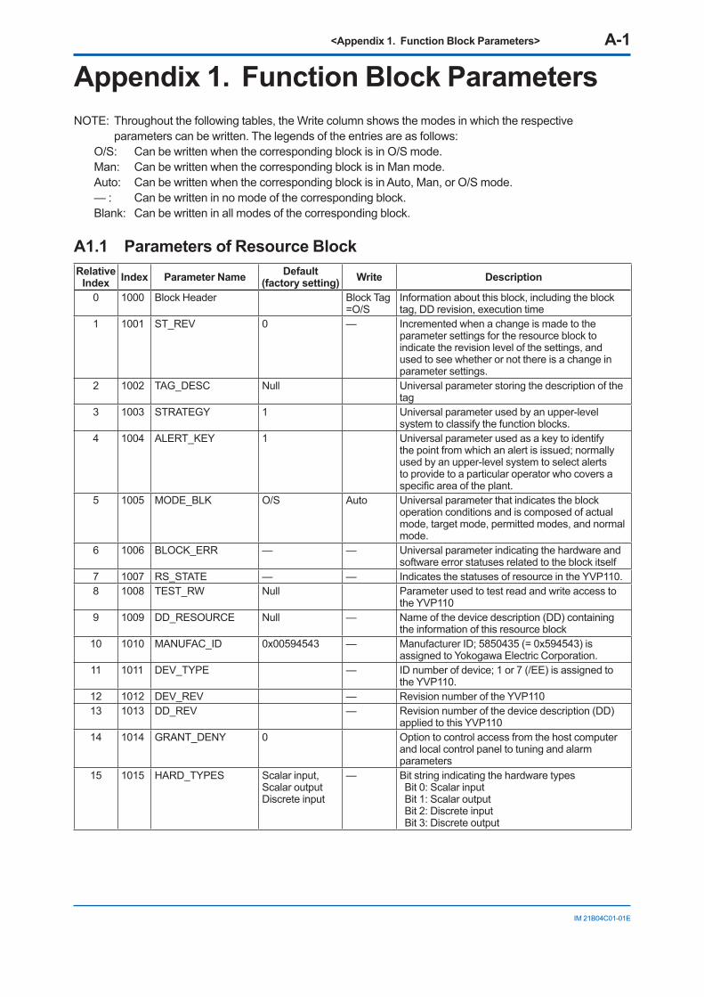
<Appendix 1. Function Block Parameters> A-1
IM 21B04C01-01E
Appendix 1. Function Block ParametersNOTE: Throughout the following tables, the Write column shows the modes in which the respective
parameters can be written. The legends of the entries are as follows: O/S: Can be written when the corresponding block is in O/S mode. Man: Can be written when the corresponding block is in Man mode. Auto: Can be written when the corresponding block is in Auto, Man, or O/S mode. — : Can be written in no mode of the corresponding block. Blank: Can be written in all modes of the corresponding block.
A1.1 Parameters of Resource BlockRelative
Index Index Parameter Name Default (factory setting) Write Description
0 1000 Block Header Block Tag =O/S
Information about this block, including the block tag, DD revision, execution time
1 1001 ST_REV 0 — Incremented when a change is made to the parameter settings for the resource block to indicate the revision level of the settings, and used to see whether or not there is a change in parameter settings.
2 1002 TAG_DESC Null Universal parameter storing the description of the tag
3 1003 STRATEGY 1 Universal parameter used by an upper-level system to classify the function blocks.
4 1004 ALERT_KEY 1 Universal parameter used as a key to identify the point from which an alert is issued; normally used by an upper-level system to select alerts to provide to a particular operator who covers a specific area of the plant.
5 1005 MODE_BLK O/S Auto Universal parameter that indicates the block operation conditions and is composed of actual mode, target mode, permitted modes, and normal mode.
6 1006 BLOCK_ERR — — Universal parameter indicating the hardware and software error statuses related to the block itself
7 1007 RS_STATE — — Indicates the statuses of resource in the YVP110.8 1008 TEST_RW Null Parameter used to test read and write access to
the YVP1109 1009 DD_RESOURCE Null — Name of the device description (DD) containing
the information of this resource block10 1010 MANUFAC_ID 0x00594543 — Manufacturer ID; 5850435 (= 0x594543) is
assigned to Yokogawa Electric Corporation.11 1011 DEV_TYPE — ID number of device; 1 or 7 (/EE) is assigned to
the YVP110.12 1012 DEV_REV — Revision number of the YVP11013 1013 DD_REV — Revision number of the device description (DD)
applied to this YVP11014 1014 GRANT_DENY 0 Option to control access from the host computer
and local control panel to tuning and alarm parameters
15 1015 HARD_TYPES Scalar input, Scalar outputDiscrete input
— Bit string indicating the hardware types Bit 0: Scalar input Bit 1: Scalar output Bit 2: Discrete input Bit 3: Discrete output
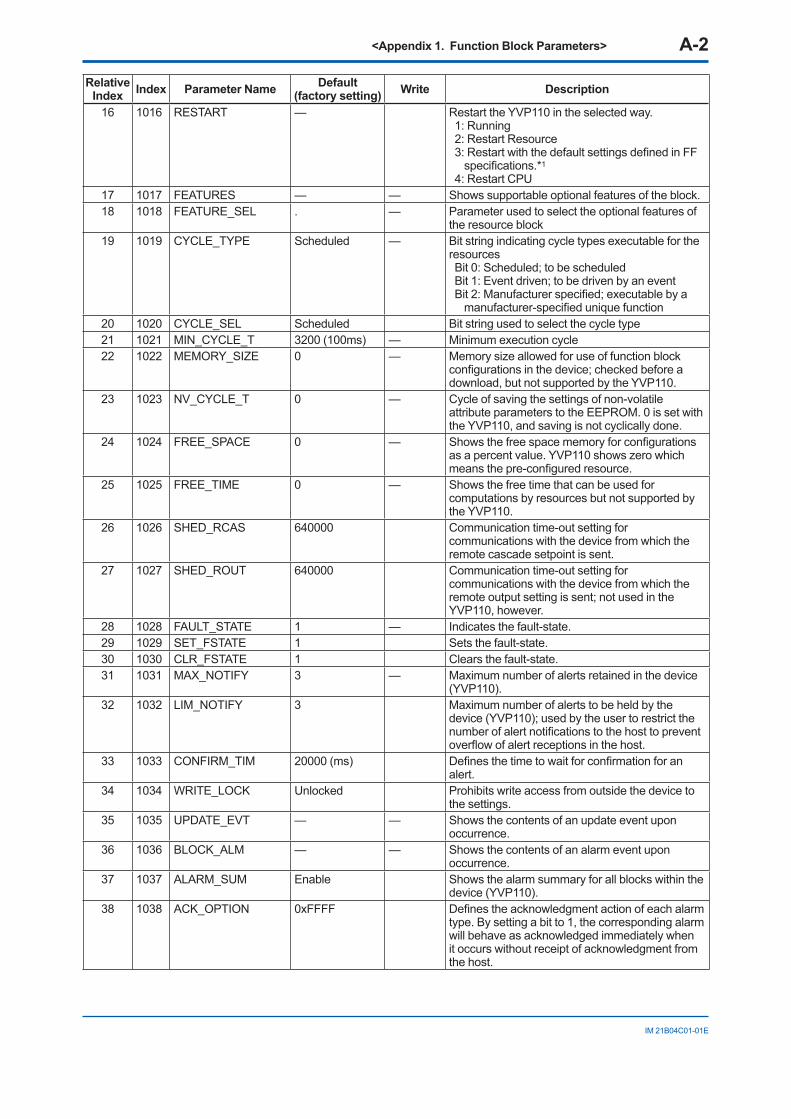
<Appendix 1. Function Block Parameters> A-2
IM 21B04C01-01E
Relative Index Index Parameter Name Default
(factory setting) Write Description
16 1016 RESTART — Restart the YVP110 in the selected way.1: Running2: Restart Resource3: Restart with the default settings defined in FF
specifications.*1
4: Restart CPU17 1017 FEATURES — — Shows supportable optional features of the block.18 1018 FEATURE_SEL . — Parameter used to select the optional features of
the resource block19 1019 CYCLE_TYPE Scheduled — Bit string indicating cycle types executable for the
resources Bit 0: Scheduled; to be scheduled Bit 1: Event driven; to be driven by an event Bit 2: Manufacturer specified; executable by a
manufacturer-specified unique function20 1020 CYCLE_SEL Scheduled Bit string used to select the cycle type21 1021 MIN_CYCLE_T 3200 (100ms) — Minimum execution cycle22 1022 MEMORY_SIZE 0 — Memory size allowed for use of function block
configurations in the device; checked before a download, but not supported by the YVP110.
23 1023 NV_CYCLE_T 0 — Cycle of saving the settings of non-volatile attribute parameters to the EEPROM. 0 is set with the YVP110, and saving is not cyclically done.
24 1024 FREE_SPACE 0 — Shows the free space memory for configurations as a percent value. YVP110 shows zero which means the pre-configured resource.
25 1025 FREE_TIME 0 — Shows the free time that can be used for computations by resources but not supported by the YVP110.
26 1026 SHED_RCAS 640000 Communication time-out setting for communications with the device from which the remote cascade setpoint is sent.
27 1027 SHED_ROUT 640000 Communication time-out setting for communications with the device from which the remote output setting is sent; not used in the YVP110, however.
28 1028 FAULT_STATE 1 — Indicates the fault-state.29 1029 SET_FSTATE 1 Sets the fault-state.30 1030 CLR_FSTATE 1 Clears the fault-state.31 1031 MAX_NOTIFY 3 — Maximum number of alerts retained in the device
(YVP110).32 1032 LIM_NOTIFY 3 Maximum number of alerts to be held by the
device (YVP110); used by the user to restrict the number of alert notifications to the host to prevent overflow of alert receptions in the host.
33 1033 CONFIRM_TIM 20000 (ms) Defines the time to wait for confirmation for an alert.
34 1034 WRITE_LOCK Unlocked Prohibits write access from outside the device to the settings.
35 1035 UPDATE_EVT — — Shows the contents of an update event upon occurrence.
36 1036 BLOCK_ALM — — Shows the contents of an alarm event upon occurrence.
37 1037 ALARM_SUM Enable Shows the alarm summary for all blocks within the device (YVP110).
38 1038 ACK_OPTION 0xFFFF Defines the acknowledgment action of each alarm type. By setting a bit to 1, the corresponding alarm will behave as acknowledged immediately when it occurs without receipt of acknowledgment from the host.
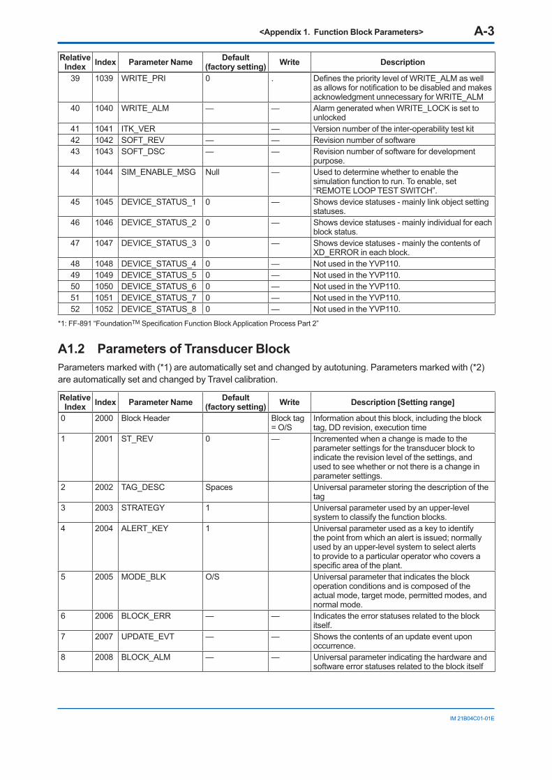
<Appendix 1. Function Block Parameters> A-3
IM 21B04C01-01E
Relative Index Index Parameter Name Default
(factory setting) Write Description
39 1039 WRITE_PRI 0 . Defines the priority level of WRITE_ALM as well as allows for notification to be disabled and makes acknowledgment unnecessary for WRITE_ALM
40 1040 WRITE_ALM — — Alarm generated when WRITE_LOCK is set to unlocked
41 1041 ITK_VER — Version number of the inter-operability test kit42 1042 SOFT_REV — — Revision number of software43 1043 SOFT_DSC — — Revision number of software for development
purpose.44 1044 SIM_ENABLE_MSG Null — Used to determine whether to enable the
simulation function to run. To enable, set “REMOTE LOOP TEST SWITCH”.
45 1045 DEVICE_STATUS_1 0 — Shows device statuses - mainly link object setting statuses.
46 1046 DEVICE_STATUS_2 0 — Shows device statuses - mainly individual for each block status.
47 1047 DEVICE_STATUS_3 0 — Shows device statuses - mainly the contents of XD_ERROR in each block.
48 1048 DEVICE_STATUS_4 0 — Not used in the YVP110.49 1049 DEVICE_STATUS_5 0 — Not used in the YVP110.50 1050 DEVICE_STATUS_6 0 — Not used in the YVP110.51 1051 DEVICE_STATUS_7 0 — Not used in the YVP110.52 1052 DEVICE_STATUS_8 0 — Not used in the YVP110.
*1: FF-891 “FoundationTM Specification Function Block Application Process Part 2”
A1.2 Parameters of Transducer Block Parameters marked with (*1) are automatically set and changed by autotuning. Parameters marked with (*2) are automatically set and changed by Travel calibration.
Relative Index Index Parameter Name Default
(factory setting) Write Description [Setting range]
0 2000 Block Header Block tag = O/S
Information about this block, including the block tag, DD revision, execution time
1 2001 ST_REV 0 — Incremented when a change is made to the parameter settings for the transducer block to indicate the revision level of the settings, and used to see whether or not there is a change in parameter settings.
2 2002 TAG_DESC Spaces Universal parameter storing the description of the tag
3 2003 STRATEGY 1 Universal parameter used by an upper-level system to classify the function blocks.
4 2004 ALERT_KEY 1 Universal parameter used as a key to identify the point from which an alert is issued; normally used by an upper-level system to select alerts to provide to a particular operator who covers a specific area of the plant.
5 2005 MODE_BLK O/S Universal parameter that indicates the block operation conditions and is composed of the actual mode, target mode, permitted modes, and normal mode.
6 2006 BLOCK_ERR — — Indicates the error statuses related to the block itself.
7 2007 UPDATE_EVT — — Shows the contents of an update event upon occurrence.
8 2008 BLOCK_ALM — — Universal parameter indicating the hardware and software error statuses related to the block itself
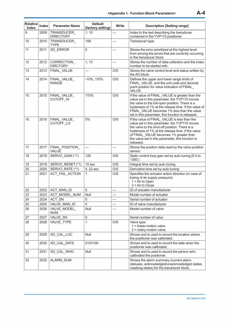
<Appendix 1. Function Block Parameters> A-4
IM 21B04C01-01E
Relative Index Index Parameter Name Default
(factory setting) Write Description [Setting range]
9 2009 TRANSDUCER_DIRECTORY
1, 10 — Index to the text describing the transducer contained in the YVP110 positioner
10 2010 TRANSDUCER_TYPE
106 — Transducer type
11 2011 XD_ERROR 0 — Stores the error prioritized at the highest level from among the errors that are currently occurring in the transducer block.
12 2012 CORRECTION_DIRCTORY
1, 13 — Stores the number of data collection and the index number to be started with.
13 2013 FINAL_VALUE — O/S Stores the valve control level and status written by the AO block.
14 2014 FINAL_VALUE_RANGE
-10%, 110% O/S Defines the upper and lower range limits of FINAL_VALUE, and the unit code and decimal point position for value indication of FINAL_VALUE.
15 2015 FINAL_VALUE_CUTOFF_HI
110% O/S If the value of FINAL_VALUE is greater than the value set in this parameter, the YVP110 moves the valve to the full-open position. There is a hysteresis of 1% at the release time. If the value of FINAL_VALUE becomes 1% less than the value set in this parameter, this function is released.
16 2016 FINAL_VALUE_CUTOFF_LO
0% O/S If the value of FINAL_VALUE is less than the value set in this parameter, the YVP110 moves the valve to the shut-off position. There is a hysteresis of 1% at the release time. If the value of FINAL_VALUE becomes 1% greater than the value set in this parameter, this function is released.
17 2017 FINAL_POSITION_VALUE
— — Stores the position data read by the valve position sensor.
18 2018 SERVO_GAIN (*1) 120 O/S Static control loop gain set by auto tuning [0.5 to 1300 ]
19 2019 SERVO_RESET (*1) 15 sec O/S Integral time set by auto tuning20 2020 SERVO_RATE (*1) 0. 22 sec O/S Derivative time set by auto tuning21 2021 ACT_FAIL_ACTION 1 O/S Specifies the actuator action direction (in case of
losing of air supply pressure): 1 = Air to Open 2 = Air to Close
22 2022 ACT_MAN_ID 0 — ID of actuator manufacturer23 2023 ACT_MODEL_NUM Null — Model number of actuator24 2024 ACT_SN 0 — Serial number of actuator25 2025 VALVE_MAN_ID 0 — ID of valve manufacturer26 2026 VALVE_MODEL_
NUMNull — Model number of valve
27 2027 VALVE_SN 0 Serial number of valve28 2028 VALVE_TYPE 1 O/S Valve type:
1 = linear-motion valve 2 = rotary-motion valve
29 2029 XD_CAL_LOC Null Shows and is used to record the location where the positioner was calibrated.
30 2030 XD_CAL_DATE 01/01/00 Shows and is used to record the date when the positioner was calibrated.
31 2031 XD_CAL_WHO Null Shows and is used to record the person who calibrated the positioner.
32 2032 ALARM_SUM Shows the alarm summary (current alarm statuses, acknowledged/unacknowledged states, masking states) for the transducer block.
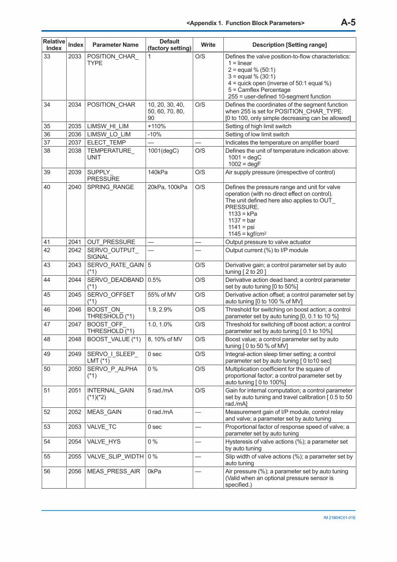
<Appendix 1. Function Block Parameters> A-5
IM 21B04C01-01E
Relative Index Index Parameter Name Default
(factory setting) Write Description [Setting range]
33 2033 POSITION_CHAR_TYPE
1 O/S Defines the valve position-to-flow characteristics: 1 = linear 2 = equal % (50:1) 3 = equal % (30:1) 4 = quick open (inverse of 50:1 equal %) 5 = Camflex Percentage 255 = user-defined 10-segment function
34 2034 POSITION_CHAR 10, 20, 30, 40, 50, 60, 70, 80, 90
O/S Defines the coordinates of the segment function when 255 is set for POSITION_CHAR_TYPE. [0 to 100, only simple decreasing can be allowed]
35 2035 LIMSW_HI_LIM +110% Setting of high limit switch36 2036 LIMSW_LO_LIM -10% Setting of low limit switch37 2037 ELECT_TEMP — — Indicates the temperature on amplifier board38 2038 TEMPERATURE_
UNIT1001(degC) O/S Defines the unit of temperature indication above:
1001 = degC 1002 = degF
39 2039 SUPPLY_PRESSURE
140kPa O/S Air supply pressure (irrespective of control)
40 2040 SPRING_RANGE 20kPa, 100kPa O/S Defines the pressure range and unit for valve operation (with no direct effect on control). The unit defined here also applies to OUT_PRESSURE. 1133 = kPa 1137 = bar 1141 = psi 1145 = kgf/cm2
41 2041 OUT_PRESSURE — — Output pressure to valve actuator42 2042 SERVO_OUTPUT_
SIGNAL— — Output current (%) to I/P module
43 2043 SERVO_RATE_GAIN (*1)
5 O/S Derivative gain; a control parameter set by auto tuning [ 2 to 20 ]
44 2044 SERVO_DEADBAND (*1)
0.5% O/S Derivative action dead band; a control parameter set by auto tuning [0 to 50%]
45 2045 SERVO_OFFSET (*1)
55% of MV O/S Derivative action offset; a control parameter set by auto tuning [0 to 100 % of MV]
46 2046 BOOST_ON_THRESHOLD (*1)
1.9, 2.9% O/S Threshold for switching on boost action; a control parameter set by auto tuning [0, 0.1 to 10 %]
47 2047 BOOST_OFF_THRESHOLD (*1)
1.0, 1.0% O/S Threshold for switching off boost action; a control parameter set by auto tuning [ 0.1 to 10%]
48 2048 BOOST_VALUE (*1) 8, 10% of MV O/S Boost value; a control parameter set by auto tuning [ 0 to 50 % of MV]
49 2049 SERVO_I_SLEEP_LMT (*1)
0 sec O/S Integral-action sleep timer setting; a control parameter set by auto tuning [ 0 to10 sec]
50 2050 SERVO_P_ALPHA (*1)
0 % O/S Multiplication coefficient for the square of proportional factor; a control parameter set by auto tuning [ 0 to 100%]
51 2051 INTERNAL_GAIN (*1)(*2)
5 rad./mA O/S Gain for internal computation; a control parameter set by auto tuning and travel calibration [ 0.5 to 50 rad./mA]
52 2052 MEAS_GAIN 0 rad./mA — Measurement gain of I/P module, control relay and valve; a parameter set by auto tuning
53 2053 VALVE_TC 0 sec — Proportional factor of response speed of valve; a parameter set by auto tuning
54 2054 VALVE_HYS 0 % — Hysteresis of valve actions (%); a parameter set by auto tuning
55 2055 VALVE_SLIP_WIDTH 0 % — Slip width of valve actions (%); a parameter set by auto tuning
56 2056 MEAS_PRESS_AIR 0kPa — Air pressure (%); a parameter set by auto tuning (Valid when an optional pressure sensor is specified.)
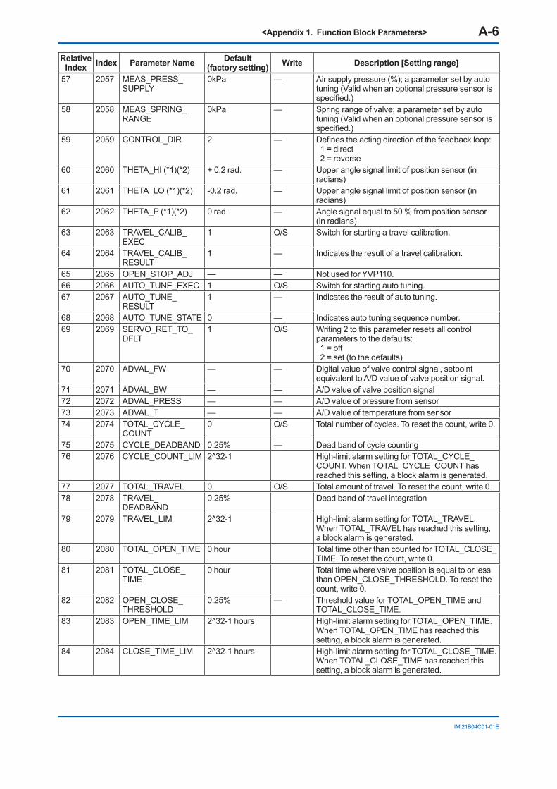
<Appendix 1. Function Block Parameters> A-6
IM 21B04C01-01E
Relative Index Index Parameter Name Default
(factory setting) Write Description [Setting range]
57 2057 MEAS_PRESS_SUPPLY
0kPa — Air supply pressure (%); a parameter set by auto tuning (Valid when an optional pressure sensor is specified.)
58 2058 MEAS_SPRING_RANGE
0kPa — Spring range of valve; a parameter set by auto tuning (Valid when an optional pressure sensor is specified.)
59 2059 CONTROL_DIR 2 — Defines the acting direction of the feedback loop: 1 = direct 2 = reverse
60 2060 THETA_HI (*1)(*2) + 0.2 rad. — Upper angle signal limit of position sensor (in radians)
61 2061 THETA_LO (*1)(*2) -0.2 rad. — Upper angle signal limit of position sensor (in radians)
62 2062 THETA_P (*1)(*2) 0 rad. — Angle signal equal to 50 % from position sensor (in radians)
63 2063 TRAVEL_CALIB_EXEC
1 O/S Switch for starting a travel calibration.
64 2064 TRAVEL_CALIB_RESULT
1 — Indicates the result of a travel calibration.
65 2065 OPEN_STOP_ADJ — — Not used for YVP110.66 2066 AUTO_TUNE_EXEC 1 O/S Switch for starting auto tuning.67 2067 AUTO_TUNE_
RESULT1 — Indicates the result of auto tuning.
68 2068 AUTO_TUNE_STATE 0 — Indicates auto tuning sequence number.69 2069 SERVO_RET_TO_
DFLT1 O/S Writing 2 to this parameter resets all control
parameters to the defaults: 1 = off 2 = set (to the defaults)
70 2070 ADVAL_FW — — Digital value of valve control signal, setpoint equivalent to A/D value of valve position signal.
71 2071 ADVAL_BW — — A/D value of valve position signal72 2072 ADVAL_PRESS — — A/D value of pressure from sensor73 2073 ADVAL_T — — A/D value of temperature from sensor74 2074 TOTAL_CYCLE_
COUNT0 O/S Total number of cycles. To reset the count, write 0.
75 2075 CYCLE_DEADBAND 0.25% — Dead band of cycle counting76 2076 CYCLE_COUNT_LIM 2^32-1 High-limit alarm setting for TOTAL_CYCLE_
COUNT. When TOTAL_CYCLE_COUNT has reached this setting, a block alarm is generated.
77 2077 TOTAL_TRAVEL 0 O/S Total amount of travel. To reset the count, write 0.78 2078 TRAVEL_
DEADBAND0.25% Dead band of travel integration
79 2079 TRAVEL_LIM 2^32-1 High-limit alarm setting for TOTAL_TRAVEL. When TOTAL_TRAVEL has reached this setting, a block alarm is generated.
80 2080 TOTAL_OPEN_TIME 0 hour Total time other than counted for TOTAL_CLOSE_TIME. To reset the count, write 0.
81 2081 TOTAL_CLOSE_TIME
0 hour Total time where valve position is equal to or less than OPEN_CLOSE_THRESHOLD. To reset the count, write 0.
82 2082 OPEN_CLOSE_THRESHOLD
0.25% — Threshold value for TOTAL_OPEN_TIME and TOTAL_CLOSE_TIME.
83 2083 OPEN_TIME_LIM 2^32-1 hours High-limit alarm setting for TOTAL_OPEN_TIME.When TOTAL_OPEN_TIME has reached this setting, a block alarm is generated.
84 2084 CLOSE_TIME_LIM 2^32-1 hours High-limit alarm setting for TOTAL_CLOSE_TIME.When TOTAL_CLOSE_TIME has reached this setting, a block alarm is generated.
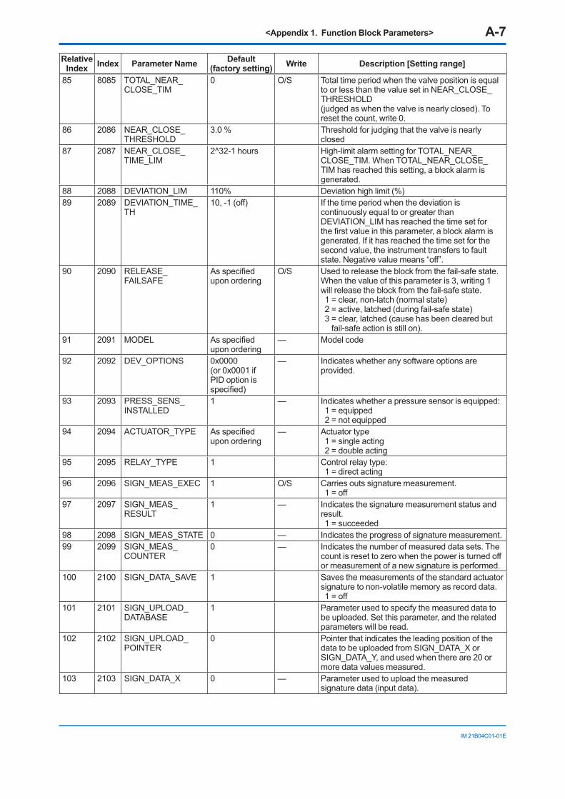
<Appendix 1. Function Block Parameters> A-7
IM 21B04C01-01E
Relative Index Index Parameter Name Default
(factory setting) Write Description [Setting range]
85 8085 TOTAL_NEAR_CLOSE_TIM
0 O/S Total time period when the valve position is equal to or less than the value set in NEAR_CLOSE_THRESHOLD(judged as when the valve is nearly closed). To reset the count, write 0.
86 2086 NEAR_CLOSE_THRESHOLD
3.0 % Threshold for judging that the valve is nearly closed
87 2087 NEAR_CLOSE_TIME_LIM
2^32-1 hours High-limit alarm setting for TOTAL_NEAR_CLOSE_TIM. When TOTAL_NEAR_CLOSE_TIM has reached this setting, a block alarm is generated.
88 2088 DEVIATION_LIM 110% Deviation high limit (%)89 2089 DEVIATION_TIME_
TH10, -1 (off) If the time period when the deviation is
continuously equal to or greater than DEVIATION_LIM has reached the time set for the first value in this parameter, a block alarm is generated. If it has reached the time set for the second value, the instrument transfers to fault state. Negative value means “off”.
90 2090 RELEASE_FAILSAFE
As specified upon ordering
O/S Used to release the block from the fail-safe state. When the value of this parameter is 3, writing 1 will release the block from the fail-safe state. 1 = clear, non-latch (normal state) 2 = active, latched (during fail-safe state) 3 = clear, latched (cause has been cleared but
fail-safe action is still on).91 2091 MODEL As specified
upon ordering— Model code
92 2092 DEV_OPTIONS 0x0000 (or 0x0001 if PID option is specified)
— Indicates whether any software options are provided.
93 2093 PRESS_SENS_INSTALLED
1 — Indicates whether a pressure sensor is equipped: 1 = equipped 2 = not equipped
94 2094 ACTUATOR_TYPE As specified upon ordering
— Actuator type 1 = single acting 2 = double acting
95 2095 RELAY_TYPE 1 Control relay type: 1 = direct acting
96 2096 SIGN_MEAS_EXEC 1 O/S Carries outs signature measurement. 1 = off
97 2097 SIGN_MEAS_RESULT
1 — Indicates the signature measurement status and result. 1 = succeeded
98 2098 SIGN_MEAS_STATE 0 — Indicates the progress of signature measurement.99 2099 SIGN_MEAS_
COUNTER0 — Indicates the number of measured data sets. The
count is reset to zero when the power is turned off or measurement of a new signature is performed.
100 2100 SIGN_DATA_SAVE 1 Saves the measurements of the standard actuator signature to non-volatile memory as record data. 1 = off
101 2101 SIGN_UPLOAD_DATABASE
1 Parameter used to specify the measured data to be uploaded. Set this parameter, and the related parameters will be read.
102 2102 SIGN_UPLOAD_POINTER
0 Pointer that indicates the leading position of the data to be uploaded from SIGN_DATA_X or SIGN_DATA_Y, and used when there are 20 or more data values measured.
103 2103 SIGN_DATA_X 0 — Parameter used to upload the measured signature data (input data).
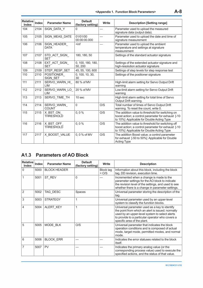
<Appendix 1. Function Block Parameters> A-8
IM 21B04C01-01E
Relative Index Index Parameter Name Default
(factory setting) Write Description [Setting range]
104 2104 SIGN_DATA_Y 0 — Parameter used to upload the measured signature data (output data).
105 2105 SIGN_MEAS_DATE 01/01/00 00:00:00.000
— Parameter used to upload the date and time of signature measurement
106 2106 SIGN_HEADER_DATA
+inf — Parameter used to upload the ambient temperature and settings at signature measurement
107 2107 STD_ACT_SIGN_SET
180, 180, 50 Settings of the standard actuator signature
108 2108 EXT_ACT_SIGN_SET
0, 100, 180, 180, 50, 200
Settings of the extended actuator signature and high-resolution actuator signature
109 2109 STEP_RESP_SET 45, 55, 100, 600 Settings of step levels for step response test110 2110 POSITIONER_
SIGN_SET0, 100, 10, 30, 30
Settings of the positioner signature
111 2111 SERVO_WARN_HI_LIM
80 % of MV High-limit alarm setting for Servo Output Drift warning
112 2112 SERVO_WARN_LO_LIM
20 % of MV Low-limit alarm setting for Servo Output Drift warning
113 2113 SERVO_TIME_TH 10 sec High-limit alarm setting for total time of Servo Output Drift warning.
114 2114 SERVO_WARN_COUNT
0 O/S Total number of times of Servo Output Drift warning. To reset the count, write 0.
115 2115 X_BST_ON_THRESHOLD
0, 0 % O/S The addition value to threshold for switching on boost action; a control parameter for exhaust [-10 to 10%] Applicable for Double Acting Type
116 2116 X_BST_OFF_THRESHOLD
0, 0 % O/S The addition value to threshold for switching off boost action; a control parameter for exhaust [-10 to 10%] Applicable for Double Acting Type
117 2117 X_BOOST_VALUE 0, 0 % of MV O/S The addition Boost value; a control parameter for exhaust [-50 to 50%] Applicable for Double Acting Type
A1.3 Parameters of AO Block Relative
Index Index Parameter Name Default (factory setting) Write Description
0 5000 BLOCK HEADER Block tag = O/S
Information about this block, including the block tag, DD revision, execution time.
1 5001 ST_REV 0 — Incremented when a change is made to the parameter settings for the AO block to indicate the revision level of the settings, and used to see whether there is a change in parameter settings.
2 5002 TAG_DESC Spaces Universal parameter storing the description of the tag.
3 5003 STRATEGY 1 Universal parameter used by an upper-level system to classify the function blocks.
4 5004 ALERT_KEY 1 Universal parameter used as a key to identify the point from which an alert is issued; normally used by an upper-level system to select alerts to provide to a particular operator who covers a specific area of the plant.
5 5005 MODE_BLK O/S Universal parameter that indicates the block operation conditions and is composed of actual mode, target mode, permitted modes, and normal mode.
6 5006 BLOCK_ERR — — Indicates the error statuses related to the block itself.
7 5007 PV — — Indicates the primary analog value (or the corresponding process value) used to execute the specified actions, and the status of that value.
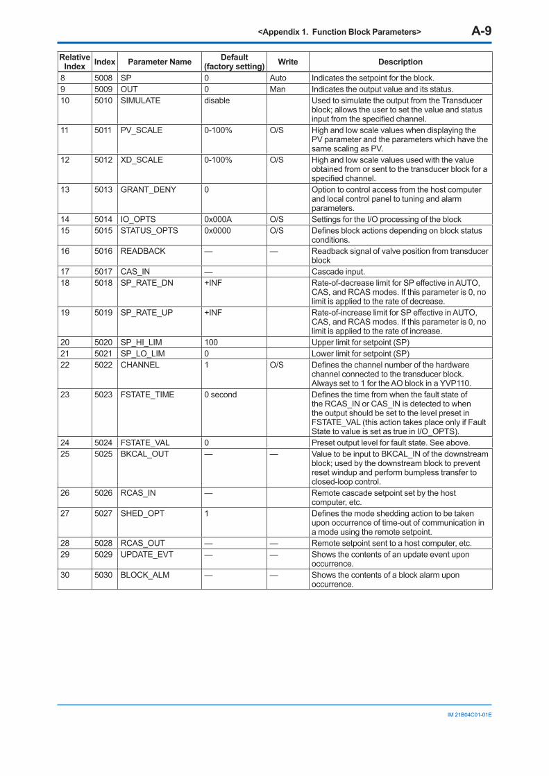
<Appendix 1. Function Block Parameters> A-9
IM 21B04C01-01E
Relative Index Index Parameter Name Default
(factory setting) Write Description
8 5008 SP 0 Auto Indicates the setpoint for the block.9 5009 OUT 0 Man Indicates the output value and its status.10 5010 SIMULATE disable Used to simulate the output from the Transducer
block; allows the user to set the value and status input from the specified channel.
11 5011 PV_SCALE 0-100% O/S High and low scale values when displaying the PV parameter and the parameters which have the same scaling as PV.
12 5012 XD_SCALE 0-100% O/S High and low scale values used with the value obtained from or sent to the transducer block for a specified channel.
13 5013 GRANT_DENY 0 Option to control access from the host computer and local control panel to tuning and alarm parameters.
14 5014 IO_OPTS 0x000A O/S Settings for the I/O processing of the block15 5015 STATUS_OPTS 0x0000 O/S Defines block actions depending on block status
conditions.16 5016 READBACK — — Readback signal of valve position from transducer
block17 5017 CAS_IN — Cascade input.18 5018 SP_RATE_DN +INF Rate-of-decrease limit for SP effective in AUTO,
CAS, and RCAS modes. If this parameter is 0, no limit is applied to the rate of decrease.
19 5019 SP_RATE_UP +INF Rate-of-increase limit for SP effective in AUTO, CAS, and RCAS modes. If this parameter is 0, no limit is applied to the rate of increase.
20 5020 SP_HI_LIM 100 Upper limit for setpoint (SP)21 5021 SP_LO_LIM 0 Lower limit for setpoint (SP)22 5022 CHANNEL 1 O/S Defines the channel number of the hardware
channel connected to the transducer block. Always set to 1 for the AO block in a YVP110.
23 5023 FSTATE_TIME 0 second Defines the time from when the fault state of the RCAS_IN or CAS_IN is detected to when the output should be set to the level preset in FSTATE_VAL (this action takes place only if Fault State to value is set as true in I/O_OPTS).
24 5024 FSTATE_VAL 0 Preset output level for fault state. See above.25 5025 BKCAL_OUT — — Value to be input to BKCAL_IN of the downstream
block; used by the downstream block to prevent reset windup and perform bumpless transfer to closed-loop control.
26 5026 RCAS_IN — Remote cascade setpoint set by the host computer, etc.
27 5027 SHED_OPT 1 Defines the mode shedding action to be taken upon occurrence of time-out of communication in a mode using the remote setpoint.
28 5028 RCAS_OUT — — Remote setpoint sent to a host computer, etc.29 5029 UPDATE_EVT — — Shows the contents of an update event upon
occurrence.30 5030 BLOCK_ALM — — Shows the contents of a block alarm upon
occurrence.
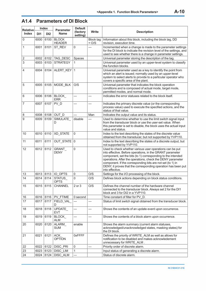
<Appendix 1. Function Block Parameters> A-10
IM 21B04C01-01E
A1.4 Parameters of DI Block Relative
IndexIndex Parameter
NameDefault (factory setting)
Write Description DI1 DI2
0 6000 6100 BLOCK HEADER
Block tag = O/S
Information about this block, including the block tag, DD revision, execution time.
1 6001 6101 ST_REV 0 — Incremented when a change is made to the parameter settings for the DI block to indicate the revision level of the settings, and used to see whether there is a change in parameter settings.
2 6002 6102 TAG_DESC Spaces Universal parameter storing the description of the tag.3 6003 6103 STRATEGY 1 Universal parameter used by an upper-level system to classify
the function blocks.4 6004 6104 ALERT_KEY 1 Universal parameter used as a key to identify the point from
which an alert is issued; normally used by an upper-level system to select alerts to provide to a particular operator who covers a specific area of the plant.
5 6005 6105 MODE_BLK O/S Universal parameter that indicates the block operation conditions and is composed of actual mode, target mode, permitted modes, and normal mode.
6 6006 6106 BLOCK_ERR
— — Indicates the error statuses related to the block itself.
7 6007 6107 PV_D — — Indicates the primary discrete value (or the corresponding process value) used to execute the specified actions, and the status of that value.
8 6008 6108 OUT_D — Man Indicates the output value and its status.9 6009 6109 SIMULATE_
Ddisable — Used to determine whether to use the limit switch signal input
from the transducer block or use the user-set value. When this parameter is set to disable, the block uses the actual input value and status.
10 6010 6110 XD_STATE 0 Index to the text describing the states of the discrete value obtained from the transducer, but not supported by YVP110.
11 6011 6111 OUT_STATE 0 Index to the text describing the states of a discrete output, but not supported by YVP110.
12 6012 6112 GRANT_DENY
0 Used to check whether various user operations can be put into effective. Before operations, in the GRANT parameter component, set the bits (to 1) corresponding to the intended operations. After the operations, check the DENY parameter component. If the corresponding bits are not set (to 1) in DENY, it proves that the corresponding operation has been put into effective.
13 6013 6113 IO_OPTS 0 O/S Settings for the I/O processing of the block.14 6014 6114 STATUS_
OPTS0 O/S Defines block actions depending on block status conditions.
15 6015 6115 CHANNEL 2 or 3 O/S Defines the channel number of the hardware channel connected to the transducer block. Always set 2 for the DI1 block and 3 for DI2 in a YVP110.
16 6016 6116 PV_FTIME 0 second Time constant of filter for PV_D.17 6017 6117 FIELD_VAL_
D— — Status of limit switch signal obtained from the transducer block.
18 6018 6118 UPDATE_EVT
— — Shows the contents of an update event upon occurrence.
19 6019 6119 BLOCK_ALM
— — Shows the contents of a block alarm upon occurrence.
20 6020 6120 ALARM_SUM
enable Shows the alarm summary (current alarm statuses, acknowledged/unacknowledged states, masking states) for the DI block.
21 6021 6121 ACK_OPTION
0xFFFF Defines the priority of WRITE_ALM as well as allows for notification to be disabled and makes acknowledement unnecessary for WRITE_ALM .
22 6022 6122 DISC_PRI 0 — Priority order of discrete alarm.23 6023 6123 DISC_LIM 1 Input status of generating a discrete alarm.24 6024 6124 DISC_ALM — Status of discrete alarm.
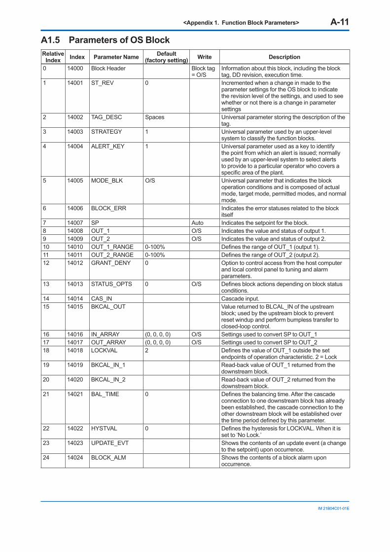
<Appendix 1. Function Block Parameters> A-11
IM 21B04C01-01E
A1.5 Parameters of OS Block Relative
Index Index Parameter Name Default (factory setting) Write Description
0 14000 Block Header Block tag = O/S
Information about this block, including the block tag, DD revision, execution time.
1 14001 ST_REV 0 Incremented when a change in made to the parameter settings for the OS block to indicate the revision level of the settings, and used to see whether or not there is a change in parameter settings
2 14002 TAG_DESC Spaces Universal parameter storing the description of the tag.
3 14003 STRATEGY 1 Universal parameter used by an upper-level system to classify the function blocks.
4 14004 ALERT_KEY 1 Universal parameter used as a key to identify the point from which an alert is issued; normally used by an upper-level system to select alerts to provide to a particular operator who covers a specific area of the plant.
5 14005 MODE_BLK O/S Universal parameter that indicates the block operation conditions and is composed of actual mode, target mode, permitted modes, and normal mode.
6 14006 BLOCK_ERR Indicates the error statuses related to the block itself
7 14007 SP Auto Indicates the setpoint for the block.8 14008 OUT_1 O/S Indicates the value and status of output 1.9 14009 OUT_2 O/S Indicates the value and status of output 2.10 14010 OUT_1_RANGE 0-100% Defines the range of OUT_1 (output 1).11 14011 OUT_2_RANGE 0-100% Defines the range of OUT_2 (output 2).12 14012 GRANT_DENY 0 Option to control access from the host computer
and local control panel to tuning and alarm parameters.
13 14013 STATUS_OPTS 0 O/S Defines block actions depending on block status conditions.
14 14014 CAS_IN Cascade input.15 14015 BKCAL_OUT Value returned to BLCAL_IN of the upstream
block; used by the upstream block to prevent reset windup and perform bumpless transfer to closed-loop control.
16 14016 IN_ARRAY (0, 0, 0, 0) O/S Settings used to convert SP to OUT_117 14017 OUT_ARRAY (0, 0, 0, 0) O/S Settings used to convert SP to OUT_218 14018 LOCKVAL 2 Defines the value of OUT_1 outside the set
endpoints of operation characteristic. 2 = Lock19 14019 BKCAL_IN_1 Read-back value of OUT_1 returned from the
downstream block.20 14020 BKCAL_IN_2 Read-back value of OUT_2 returned from the
downstream block.21 14021 BAL_TIME 0 Defines the balancing time. After the cascade
connection to one downstream block has already been established, the cascade connection to the other downstream block will be established over the time period defined by this parameter.
22 14022 HYSTVAL 0 Defines the hysteresis for LOCKVAL. When it is set to ‘No Lock.’
23 14023 UPDATE_EVT Shows the contents of an update event (a change to the setpoint) upon occurrence.
24 14024 BLOCK_ALM Shows the contents of a block alarm upon occurrence.
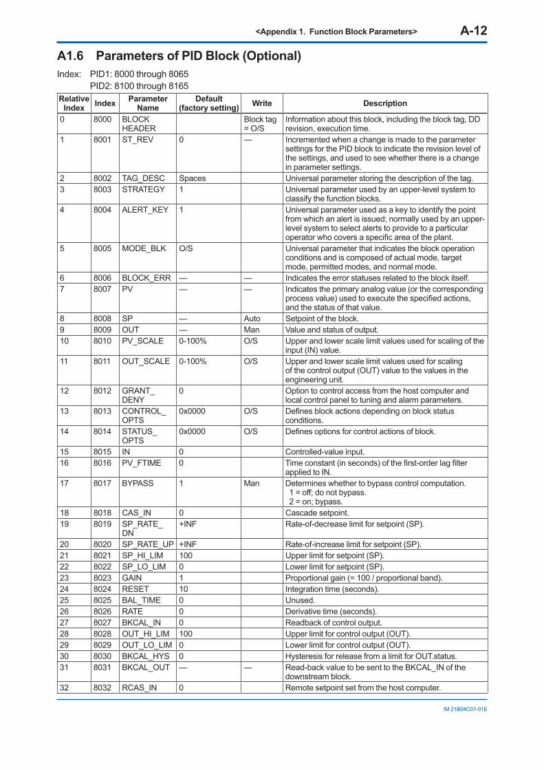
<Appendix 1. Function Block Parameters> A-12
IM 21B04C01-01E
A1.6 Parameters of PID Block (Optional) Index: PID1: 8000 through 8065 PID2: 8100 through 8165Relative
Index Index Parameter Name
Default (factory setting) Write Description
0 8000 BLOCK HEADER
Block tag = O/S
Information about this block, including the block tag, DD revision, execution time.
1 8001 ST_REV 0 — Incremented when a change is made to the parameter settings for the PID block to indicate the revision level of the settings, and used to see whether there is a change in parameter settings.
2 8002 TAG_DESC Spaces Universal parameter storing the description of the tag.3 8003 STRATEGY 1 Universal parameter used by an upper-level system to
classify the function blocks.4 8004 ALERT_KEY 1 Universal parameter used as a key to identify the point
from which an alert is issued; normally used by an upper-level system to select alerts to provide to a particular operator who covers a specific area of the plant.
5 8005 MODE_BLK O/S Universal parameter that indicates the block operation conditions and is composed of actual mode, target mode, permitted modes, and normal mode.
6 8006 BLOCK_ERR — — Indicates the error statuses related to the block itself.7 8007 PV — — Indicates the primary analog value (or the corresponding
process value) used to execute the specified actions, and the status of that value.
8 8008 SP — Auto Setpoint of the block.9 8009 OUT — Man Value and status of output.10 8010 PV_SCALE 0-100% O/S Upper and lower scale limit values used for scaling of the
input (IN) value.11 8011 OUT_SCALE 0-100% O/S Upper and lower scale limit values used for scaling
of the control output (OUT) value to the values in the engineering unit.
12 8012 GRANT_DENY
0 Option to control access from the host computer and local control panel to tuning and alarm parameters.
13 8013 CONTROL_OPTS
0x0000 O/S Defines block actions depending on block status conditions.
14 8014 STATUS_OPTS
0x0000 O/S Defines options for control actions of block.
15 8015 IN 0 Controlled-value input.16 8016 PV_FTIME 0 Time constant (in seconds) of the first-order lag filter
applied to IN.17 8017 BYPASS 1 Man Determines whether to bypass control computation.
1 = off; do not bypass.2 = on; bypass.
18 8018 CAS_IN 0 Cascade setpoint.19 8019 SP_RATE_
DN+INF Rate-of-decrease limit for setpoint (SP).
20 8020 SP_RATE_UP +INF Rate-of-increase limit for setpoint (SP).21 8021 SP_HI_LIM 100 Upper limit for setpoint (SP).22 8022 SP_LO_LIM 0 Lower limit for setpoint (SP).23 8023 GAIN 1 Proportional gain (= 100 / proportional band).24 8024 RESET 10 Integration time (seconds).25 8025 BAL_TIME 0 Unused.26 8026 RATE 0 Derivative time (seconds).27 8027 BKCAL_IN 0 Readback of control output.28 8028 OUT_HI_LIM 100 Upper limit for control output (OUT).29 8029 OUT_LO_LIM 0 Lower limit for control output (OUT).30 8030 BKCAL_HYS 0 Hysteresis for release from a limit for OUT.status.31 8031 BKCAL_OUT — — Read-back value to be sent to the BKCAL_IN of the
downstream block.32 8032 RCAS_IN 0 Remote setpoint set from the host computer.
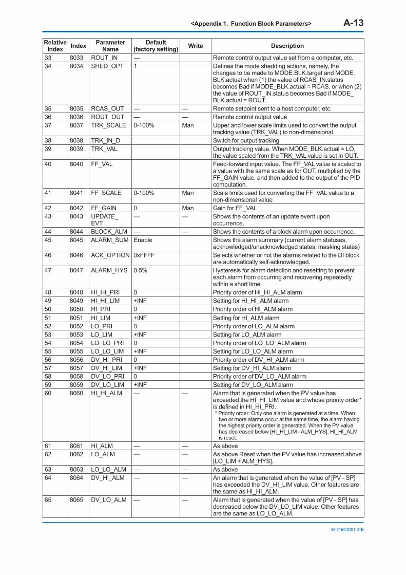
<Appendix 1. Function Block Parameters> A-13
IM 21B04C01-01E
Relative Index Index Parameter
NameDefault
(factory setting) Write Description
33 8033 ROUT_IN — Remote control output value set from a computer, etc.34 8034 SHED_OPT 1 Defines the mode shedding actions, namely, the
changes to be made to MODE.BLK.target and MODE.BLK.actual when (1) the value of RCAS_IN.status becomes Bad if MODE_BLK.actual = RCAS, or when (2) the value of ROUT_IN.status becomes Bad if MODE_BLK.actual = ROUT.
35 8035 RCAS_OUT — — Remote setpoint sent to a host computer, etc.36 8036 ROUT_OUT — — Remote control output value37 8037 TRK_SCALE 0-100% Man Upper and lower scale limits used to convert the output
tracking value (TRK_VAL) to non-dimensional.38 8038 TRK_IN_D Switch for output tracking39 8039 TRK_VAL Output tracking value. When MODE_BLK.actual = LO,
the value scaled from the TRK_VAL value is set in OUT.40 8040 FF_VAL Feed-forward input value. The FF_VAL value is scaled to
a value with the same scale as for OUT, multiplied by the FF_GAIN value, and then added to the output of the PID computation.
41 8041 FF_SCALE 0-100% Man Scale limits used for converting the FF_VAL value to a non-dimensional value
42 8042 FF_GAIN 0 Man Gain for FF_VAL43 8043 UPDATE_
EVT— — Shows the contents of an update event upon
occurrence.44 8044 BLOCK_ALM — — Shows the contents of a block alarm upon occurrence.45 8045 ALARM_SUM Enable Shows the alarm summary (current alarm statuses,
acknowledged/unacknowledged states, masking states)46 8046 ACK_OPTION 0xFFFF Selects whether or not the alarms related to the DI block
are automatically self-acknowledged.47 8047 ALARM_HYS 0.5% Hysteresis for alarm detection and resetting to prevent
each alarm from occurring and recovering repeatedly within a short time
48 8048 HI_HI_PRI 0 Priority order of HI_HI_ALM alarm49 8049 HI_HI_LIM +INF Setting for HI_HI_ALM alarm50 8050 HI_PRI 0 Priority order of HI_ALM alarm51 8051 HI_LIM +INF Setting for HI_ALM alarm52 8052 LO_PRI 0 Priority order of LO_ALM alarm53 8053 LO_LIM +INF Setting for LO_ALM alarm54 8054 LO_LO_PRI 0 Priority order of LO_LO_ALM alarm55 8055 LO_LO_LIM +INF Setting for LO_LO_ALM alarm56 8056 DV_HI_PRI 0 Priority order of DV_HI_ALM alarm57 8057 DV_HI_LIM +INF Setting for DV_HI_ALM alarm58 8058 DV_LO_PRI 0 Priority order of DV_LO_ALM alarm59 8059 DV_LO_LIM +INF Setting for DV_LO_ALM alarm60 8060 HI_HI_ALM — — Alarm that is generated when the PV value has
exceeded the HI_HI_LIM value and whose priority order* is defined in HI_HI_PRI. * Priority order: Only one alarm is generated at a time. When
two or more alarms occur at the same time, the alarm having the highest priority order is generated. When the PV value has decreased below [HI_HI_LIM - ALM_HYS], HI_HI_ALM is reset.
61 8061 HI_ALM — — As above62 8062 LO_ALM — — As above Reset when the PV value has increased above
[LO_LIM + ALM_HYS].63 8063 LO_LO_ALM — — As above64 8064 DV_HI_ALM — — An alarm that is generated when the value of [PV - SP]
has exceeded the DV_HI_LIM value. Other features are the same as HI_HI_ALM.
65 8065 DV_LO_ALM — — Alarm that is generated when the value of [PV - SP] has decreased below the DV_LO_LIM value. Other features are the same as LO_LO_ALM.
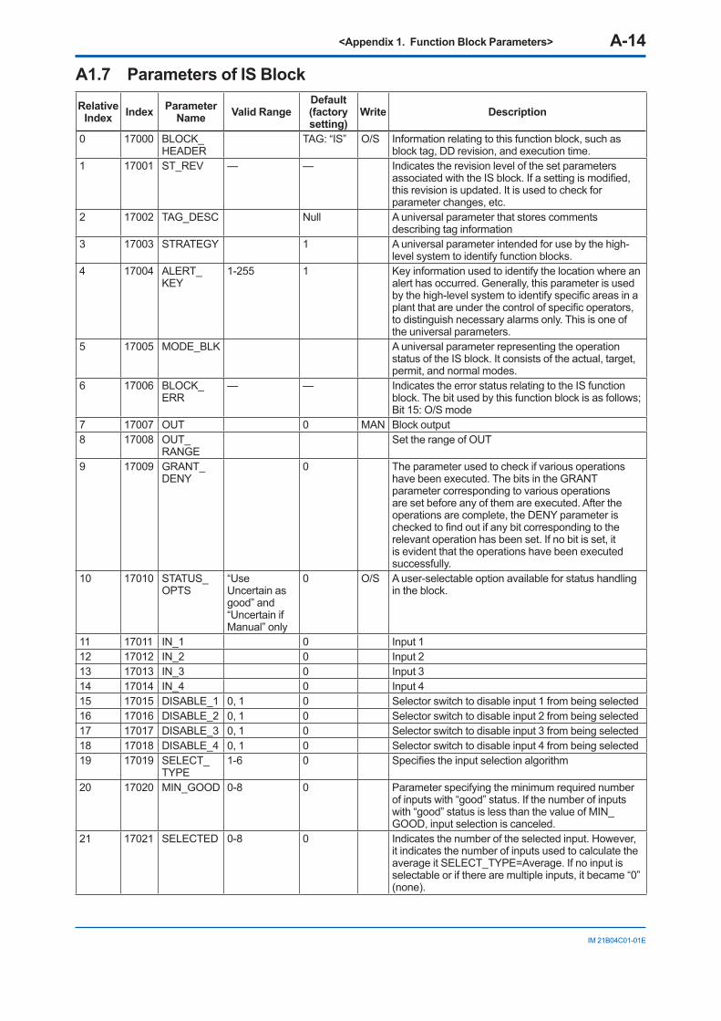
<Appendix 1. Function Block Parameters> A-14
IM 21B04C01-01E
A1.7 Parameters of IS BlockRelative
Index Index Parameter Name Valid Range
Default (factory setting)
Write Description
0 17000 BLOCK_HEADER
TAG: “IS” O/S Information relating to this function block, such as block tag, DD revision, and execution time.
1 17001 ST_REV — — Indicates the revision level of the set parameters associated with the IS block. If a setting is modified, this revision is updated. It is used to check for parameter changes, etc.
2 17002 TAG_DESC Null A universal parameter that stores comments describing tag information
3 17003 STRATEGY 1 A universal parameter intended for use by the high-level system to identify function blocks.
4 17004 ALERT_KEY
1-255 1 Key information used to identify the location where an alert has occurred. Generally, this parameter is used by the high-level system to identify specific areas in a plant that are under the control of specific operators, to distinguish necessary alarms only. This is one of the universal parameters.
5 17005 MODE_BLK A universal parameter representing the operation status of the IS block. It consists of the actual, target, permit, and normal modes.
6 17006 BLOCK_ERR
— — Indicates the error status relating to the IS function block. The bit used by this function block is as follows; Bit 15: O/S mode
7 17007 OUT 0 MAN Block output8 17008 OUT_
RANGESet the range of OUT
9 17009 GRANT_DENY
0 The parameter used to check if various operations have been executed. The bits in the GRANT parameter corresponding to various operations are set before any of them are executed. After the operations are complete, the DENY parameter is checked to find out if any bit corresponding to the relevant operation has been set. If no bit is set, it is evident that the operations have been executed successfully.
10 17010 STATUS_OPTS
“Use Uncertain as good” and “Uncertain if Manual” only
0 O/S A user-selectable option available for status handling in the block.
11 17011 IN_1 0 Input 112 17012 IN_2 0 Input 213 17013 IN_3 0 Input 314 17014 IN_4 0 Input 415 17015 DISABLE_1 0, 1 0 Selector switch to disable input 1 from being selected16 17016 DISABLE_2 0, 1 0 Selector switch to disable input 2 from being selected17 17017 DISABLE_3 0, 1 0 Selector switch to disable input 3 from being selected18 17018 DISABLE_4 0, 1 0 Selector switch to disable input 4 from being selected19 17019 SELECT_
TYPE1-6 0 Specifies the input selection algorithm
20 17020 MIN_GOOD 0-8 0 Parameter specifying the minimum required number of inputs with “good” status. If the number of inputs with “good” status is less than the value of MIN_GOOD, input selection is canceled.
21 17021 SELECTED 0-8 0 Indicates the number of the selected input. However, it indicates the number of inputs used to calculate the average it SELECT_TYPE=Average. If no input is selectable or if there are multiple inputs, it became “0” (none).
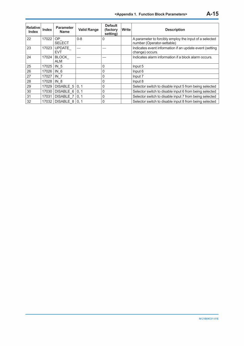
<Appendix 1. Function Block Parameters> A-15
IM 21B04C01-01E
Relative Index Index Parameter
Name Valid RangeDefault (factory setting)
Write Description
22 17022 OP_SELECT
0-8 0 A parameter to forcibly employ the input of a selected number (Operator-settable)
23 17023 UPDATE_EVT
— — Indicates event information if an update event (setting change) occurs.
24 17024 BLOCK_ALM
— — Indicates alarm information if a block alarm occurs.
25 17025 IN_5 0 Input 526 17026 IN_6 0 Input 627 17027 IN_7 0 Input 728 17028 IN_8 0 Input 829 17029 DISABLE_5 0, 1 0 Selector switch to disable input 5 from being selected30 17030 DISABLE_6 0, 1 0 Selector switch to disable input 6 from being selected31 17031 DISABLE_7 0, 1 0 Selector switch to disable input 7 from being selected32 17032 DISABLE_8 0, 1 0 Selector switch to disable input 8 from being selected
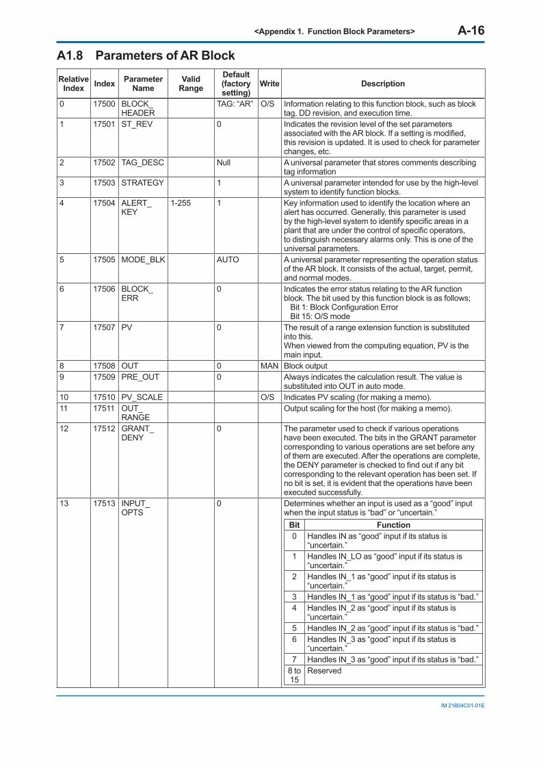
<Appendix 1. Function Block Parameters> A-16
IM 21B04C01-01E
A1.8 Parameters of AR BlockRelative
Index Index Parameter Name
Valid Range
Default (factory setting)
Write Description
0 17500 BLOCK_HEADER
TAG: “AR” O/S Information relating to this function block, such as block tag, DD revision, and execution time.
1 17501 ST_REV 0 Indicates the revision level of the set parameters associated with the AR block. If a setting is modified, this revision is updated. It is used to check for parameter changes, etc.
2 17502 TAG_DESC Null A universal parameter that stores comments describing tag information
3 17503 STRATEGY 1 A universal parameter intended for use by the high-level system to identify function blocks.
4 17504 ALERT_KEY
1-255 1 Key information used to identify the location where an alert has occurred. Generally, this parameter is used by the high-level system to identify specific areas in a plant that are under the control of specific operators, to distinguish necessary alarms only. This is one of the universal parameters.
5 17505 MODE_BLK AUTO A universal parameter representing the operation status of the AR block. It consists of the actual, target, permit, and normal modes.
6 17506 BLOCK_ERR
0 Indicates the error status relating to the AR function block. The bit used by this function block is as follows;
Bit 1: Block Configuration ErrorBit 15: O/S mode
7 17507 PV 0 The result of a range extension function is substituted into this.When viewed from the computing equation, PV is the main input.
8 17508 OUT 0 MAN Block output9 17509 PRE_OUT 0 Always indicates the calculation result. The value is
substituted into OUT in auto mode.10 17510 PV_SCALE O/S Indicates PV scaling (for making a memo).11 17511 OUT_
RANGEOutput scaling for the host (for making a memo).
12 17512 GRANT_DENY
0 The parameter used to check if various operations have been executed. The bits in the GRANT parameter corresponding to various operations are set before any of them are executed. After the operations are complete, the DENY parameter is checked to find out if any bit corresponding to the relevant operation has been set. If no bit is set, it is evident that the operations have been executed successfully.
13 17513 INPUT_OPTS
0 Determines whether an input is used as a “good” input when the input status is “bad” or “uncertain.”
Bit Function0 Handles IN as “good” input if its status is
“uncertain.”1 Handles IN_LO as “good” input if its status is
“uncertain.”2 Handles IN_1 as “good” input if its status is
“uncertain.”3 Handles IN_1 as “good” input if its status is “bad.”4 Handles IN_2 as “good” input if its status is
“uncertain.”5 Handles IN_2 as “good” input if its status is “bad.”6 Handles IN_3 as “good” input if its status is
“uncertain.”7 Handles IN_3 as “good” input if its status is “bad.”
8 to 15
Reserved
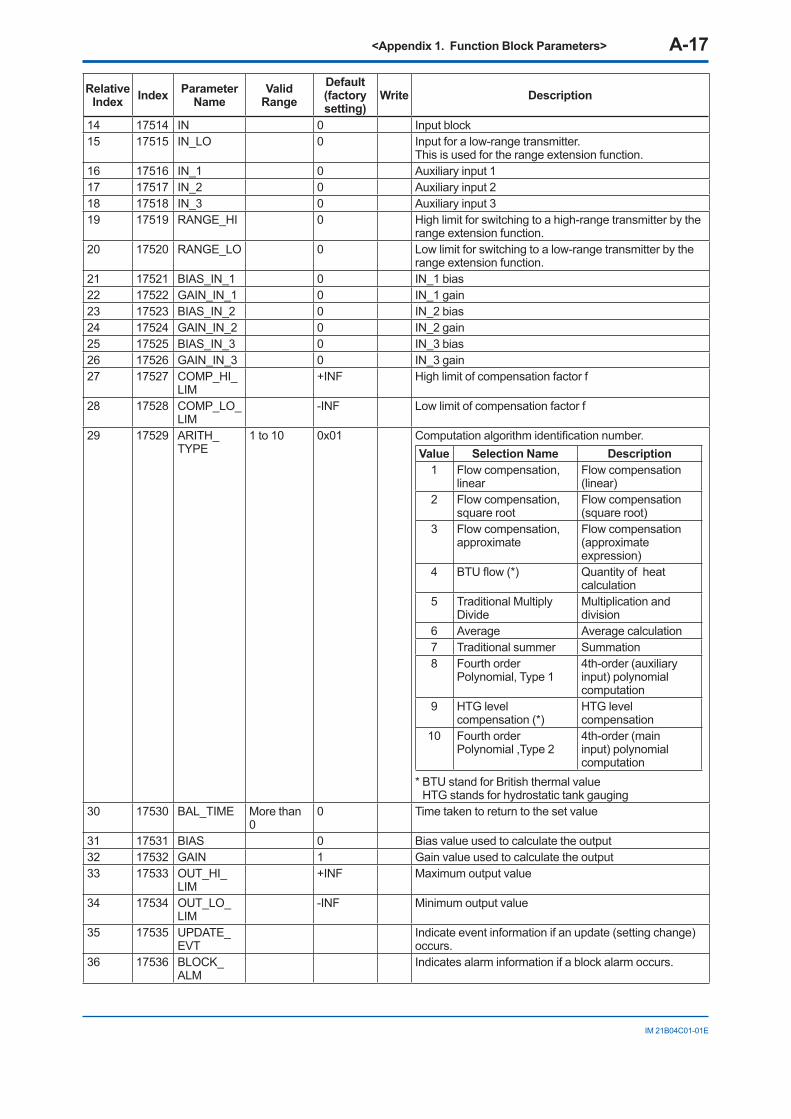
<Appendix 1. Function Block Parameters> A-17
IM 21B04C01-01E
Relative Index Index Parameter
NameValid
RangeDefault (factory setting)
Write Description
14 17514 IN 0 Input block15 17515 IN_LO 0 Input for a low-range transmitter.
This is used for the range extension function.16 17516 IN_1 0 Auxiliary input 117 17517 IN_2 0 Auxiliary input 218 17518 IN_3 0 Auxiliary input 319 17519 RANGE_HI 0 High limit for switching to a high-range transmitter by the
range extension function.20 17520 RANGE_LO 0 Low limit for switching to a low-range transmitter by the
range extension function.21 17521 BIAS_IN_1 0 IN_1 bias22 17522 GAIN_IN_1 0 IN_1 gain23 17523 BIAS_IN_2 0 IN_2 bias24 17524 GAIN_IN_2 0 IN_2 gain25 17525 BIAS_IN_3 0 IN_3 bias26 17526 GAIN_IN_3 0 IN_3 gain27 17527 COMP_HI_
LIM+INF High limit of compensation factor f
28 17528 COMP_LO_LIM
-INF Low limit of compensation factor f
29 17529 ARITH_TYPE
1 to 10 0x01 Computation algorithm identification number.Value Selection Name Description
1 Flow compensation, linear
Flow compensation (linear)
2 Flow compensation, square root
Flow compensation (square root)
3 Flow compensation, approximate
Flow compensation (approximate expression)
4 BTU flow (*) Quantity of heat calculation
5 Traditional Multiply Divide
Multiplication and division
6 Average Average calculation7 Traditional summer Summation8 Fourth order
Polynomial, Type 14th-order (auxiliary input) polynomial computation
9 HTG level compensation (*)
HTG level compensation
10 Fourth order Polynomial ,Type 2
4th-order (main input) polynomial computation
* BTU stand for British thermal value HTG stands for hydrostatic tank gauging
30 17530 BAL_TIME More than 0
0 Time taken to return to the set value
31 17531 BIAS 0 Bias value used to calculate the output32 17532 GAIN 1 Gain value used to calculate the output33 17533 OUT_HI_
LIM+INF Maximum output value
34 17534 OUT_LO_LIM
-INF Minimum output value
35 17535 UPDATE_EVT
Indicate event information if an update (setting change) occurs.
36 17536 BLOCK_ALM
Indicates alarm information if a block alarm occurs.
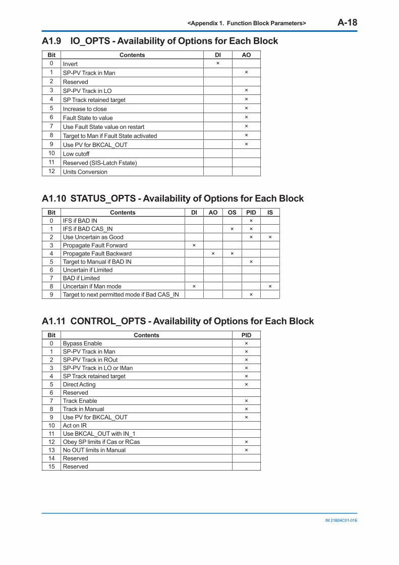
<Appendix 1. Function Block Parameters> A-18
IM 21B04C01-01E
A1.9 IO_OPTS - Availability of Options for Each Block Bit Contents DI AO0 Invert ×1 SP-PV Track in Man ×2 Reserved3 SP-PV Track in LO ×4 SP Track retained target ×5 Increase to close ×6 Fault State to value ×7 Use Fault State value on restart ×8 Target to Man if Fault State activated ×9 Use PV for BKCAL_OUT ×10 Low cutoff11 Reserved (SIS-Latch Fstate)12 Units Conversion
A1.10 STATUS_OPTS - Availability of Options for Each Block Bit Contents DI AO OS PID IS0 IFS if BAD IN ×1 IFS if BAD CAS_IN × ×2 Use Uncertain as Good × ×3 Propagate Fault Forward ×4 Propagate Fault Backward × ×5 Target to Manual if BAD IN ×6 Uncertain if Limited7 BAD if Limited8 Uncertain if Man mode × ×9 Target to next permitted mode if Bad CAS_IN ×
A1.11 CONTROL_OPTS - Availability of Options for Each Block Bit Contents PID0 Bypass Enable ×1 SP-PV Track in Man ×2 SP-PV Track in ROut ×3 SP-PV Track in LO or IMan ×4 SP Track retained target ×5 Direct Acting ×6 Reserved 7 Track Enable ×8 Track in Manual ×9 Use PV for BKCAL_OUT ×10 Act on IR 11 Use BKCAL_OUT with IN_1 12 Obey SP limits if Cas or RCas ×13 No OUT limits in Manual ×14 Reserved 15 Reserved
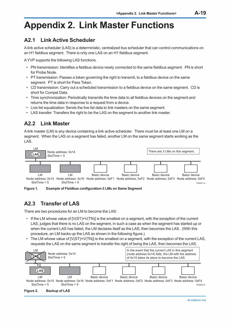
<Appendix 2. Link Master Functions> A-19
IM 21B04C01-01E
Appendix 2. Link Master FunctionsA2.1 Link Active SchedulerA link active scheduler (LAS) is a deterministic, centralized bus scheduler that can control communications on an H1 fieldbus segment. There is only one LAS on an H1 fieldbus segment.
A YVP supports the following LAS functions.
• PN transmission: Identifies a fieldbus device newly connected to the same fieldbus segment. PN is short for Probe Node.
• PT transmission: Passes a token governing the right to transmit, to a fieldbus device on the same segment. PT is short for Pass Token.
• CD transmission: Carry out a scheduled transmission to a fieldbus device on the same segment. CD is short for Compel Data.
• Time synchronization: Periodically transmits the time data to all fieldbus devices on the segment and returns the time data in response to a request from a device.
• Live list equalization: Sends the live list data to link masters on the same segment. • LAS transfer: Transfers the right to be the LAS on the segment to another link master.
A2.2 Link MasterA link master (LM) is any device containing a link active scheduler. There must be at least one LM on a segment. When the LAS on a segment has failed, another LM on the same segment starts working as the LAS.
LMNode address: 0x15
SlotTime = 5
LMNode address: 0x16
SlotTime = 5
Node address: 0x14SlotTime = 5
Basic deviceNode address: 0xF1
Basic deviceNode address: 0xF2
Basic deviceNode address: 0xF3
Basic deviceNode address: 0xF4
LASThere are 3 LMs on this segment.
LM
FA0201.ai
Figure 1. Example of Fieldbus configuration-3 LMs on Same Segment
A2.3 Transfer of LASThere are two procedures for an LM to become the LAS:
• If the LM whose value of [V(ST)×V(TN)] is the smallest on a segment, with the exception of the current LAS, judges that there is no LAS on the segment, in such a case as when the segment has started up or when the current LAS has failed, the LM declares itself as the LAS, then becomes the LAS. (With this procedure, an LM backs up the LAS as shown in the following figure.)
• The LM whose value of [V(ST)×V(TN)] is the smallest on a segment, with the exception of the current LAS, requests the LAS on the same segment to transfer the right of being the LAS, then becomes the LAS.
LMNode address: 0x15
SlotTime = 5
LMNode address: 0x16
SlotTime = 5
Node address: 0x14SlotTime = 5
Basic deviceNode address: 0xF1
Basic deviceNode address: 0xF2
Basic deviceNode address: 0xF3
Basic deviceNode address: 0xF4
LAS
LAS
In the event that the current LAS in this segment (node address 0x14) fails, the LM with the address of 0x15 takes its place to become the LAS.
LM
FA0202.ai
Figure 2. Backup of LAS
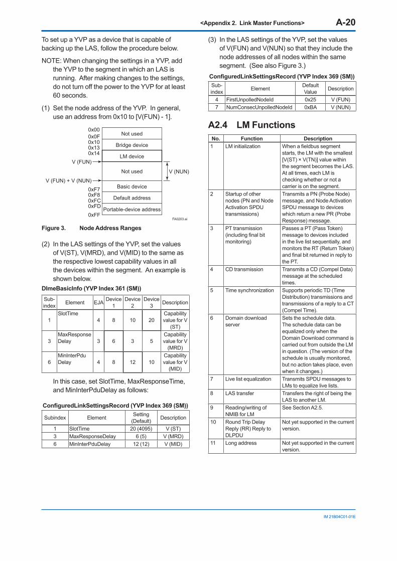
<Appendix 2. Link Master Functions> A-20
IM 21B04C01-01E
To set up a YVP as a device that is capable of backing up the LAS, follow the procedure below.
NOTE: When changing the settings in a YVP, add the YVP to the segment in which an LAS is running. After making changes to the settings, do not turn off the power to the YVP for at least 60 seconds.
(1) Set the node address of the YVP. In general, use an address from 0x10 to [V(FUN) - 1].
Bridge device
Not used
LM device
Not used
Basic device
Default address
Portable-device address
V (FUN)
V (FUN) + V (NUN)
V (NUN)
0xFF0xFD0xFC0xF80xF7
0x140x13
0x0F0x10
0x00
FA0203.ai
Figure 3. Node Address Ranges
(2) In the LAS settings of the YVP, set the values of V(ST), V(MRD), and V(MID) to the same as the respective lowest capability values in all the devices within the segment. An example is shown below.
DlmeBasicInfo (YVP Index 361 (SM))
Sub-index Element EJA Device
1Device
2Device
3 Description
1SlotTime
4 8 10 20Capability value for V
(ST)
3MaxResponse Delay 3 6 3 5
Capability value for V
(MRD)
6MinInterPdu Delay 4 8 12 10
Capability value for V
(MID)
In this case, set SlotTime, MaxResponseTime, and MinInterPduDelay as follows:
ConfiguredLinkSettingsRecord (YVP Index 369 (SM))
Subindex Element Setting (Default) Description
1 SlotTime 20 (4095) V (ST)3 MaxResponseDelay 6 (5) V (MRD)6 MinInterPduDelay 12 (12) V (MID)
(3) In the LAS settings of the YVP, set the values of V(FUN) and V(NUN) so that they include the node addresses of all nodes within the same segment. (See also Figure 3.)
ConfiguredLinkSettingsRecord (YVP Index 369 (SM)) Sub-index Element Default
Value Description
4 FirstUnpolledNodeId 0x25 V (FUN)7 NumConsecUnpolledNodeId 0xBA V (NUN)
A2.4 LM FunctionsNo. Function Description1 LM initialization When a fieldbus segment
starts, the LM with the smallest [V(ST) × V(TN)] value within the segment becomes the LAS. At all times, each LM is checking whether or not a carrier is on the segment.
2 Startup of other nodes (PN and Node Activation SPDU transmissions)
Transmits a PN (Probe Node) message, and Node Activation SPDU message to devices which return a new PR (Probe Response) message.
3 PT transmission (including final bit monitoring)
Passes a PT (Pass Token) message to devices included in the live list sequentially, and monitors the RT (Return Token) and final bit returned in reply to the PT.
4 CD transmission Transmits a CD (Compel Data) message at the scheduled times.
5 Time synchronization Supports periodic TD (Time Distribution) transmissions and transmissions of a reply to a CT (Compel Time).
6 Domain download server
Sets the schedule data. The schedule data can be equalized only when the Domain Download command is carried out from outside the LM in question. (The version of the schedule is usually monitored, but no action takes place, even when it changes.)
7 Live list equalization Transmits SPDU messages to LMs to equalize live lists.
8 LAS transfer Transfers the right of being the LAS to another LM.
9 Reading/writing of NMIB for LM
See Section A2.5.
10 Round Trip Delay Reply (RR) Reply to DLPDU
Not yet supported in the current version.
11 Long address Not yet supported in the current version.
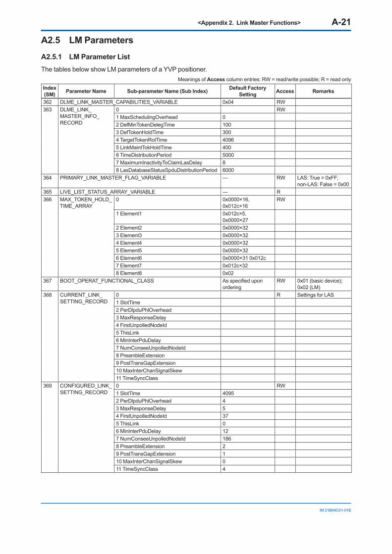
<Appendix 2. Link Master Functions> A-21
IM 21B04C01-01E
A2.5 LM ParametersA2.5.1 LM Parameter ListThe tables below show LM parameters of a YVP positioner.
Meanings of Access column entries: RW = read/write possible; R = read only Index (SM) Parameter Name Sub-parameter Name (Sub Index) Default Factory
Setting Access Remarks
362 DLME_LINK_MASTER_CAPABILITIES_VARIABLE 0x04 RW363 DLME_LINK_
MASTER_INFO_RECORD
0 RW1 MaxSchedulingOverhead 02 DefMinTokenDelegTime 1003 DefTokenHoldTime 3004 TargetTokenRotTime 40965 LinkMaintTokHoldTime 4006 TimeDistributionPeriod 50007 MaximumInactivityToClaimLasDelay 88 LasDatabaseStatusSpduDistributionPeriod 6000
364 PRIMARY_LINK_MASTER_FLAG_VARIABLE — RW LAS: True = 0xFF; non-LAS: False = 0x00
365 LIVE_LIST_STATUS_ARRAY_VARIABLE — R366 MAX_TOKEN_HOLD_
TIME_ARRAY0 0x0000×16,
0x012c×16RW
1 Element1 0x012c×5, 0x0000×27
2 Element2 0x0000×323 Element3 0x0000×324 Element4 0x0000×325 Element5 0x0000×326 Element6 0x0000×31 0x012c7 Element7 0x012c×328 Element8 0x02
367 BOOT_OPERAT_FUNCTIONAL_CLASS As specified upon ordering
RW 0x01 (basic device); 0x02 (LM)
368 CURRENT_LINK_SETTING_RECORD
0 R Settings for LAS1 SlotTime2 PerDlpduPhlOverhead3 MaxResponseDelay4 FirstUnpolledNodeId5 ThisLink6 MinInterPduDelay7 NumConseeUnpolledNodeId8 PreambleExtension9 PostTransGapExtension10 MaxInterChanSignalSkew11 TimeSyncClass
369 CONFIGURED_LINK_ SETTING_RECORD
0 RW1 SlotTime 40952 PerDlpduPhlOverhead 43 MaxResponseDelay 54 FirstUnpolledNodeId 375 ThisLink 06 MinInterPduDelay 127 NumConseeUnpolledNodeId 1868 PreambleExtension 29 PostTransGapExtension 110 MaxInterChanSignalSkew 011 TimeSyncClass 4
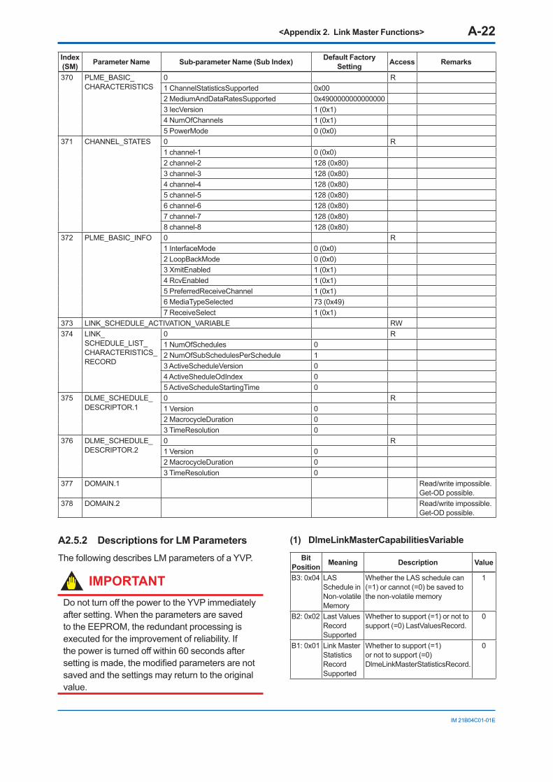
<Appendix 2. Link Master Functions> A-22
IM 21B04C01-01E
Index (SM) Parameter Name Sub-parameter Name (Sub Index) Default Factory
Setting Access Remarks
370 PLME_BASIC_CHARACTERISTICS
0 R1 ChannelStatisticsSupported 0x002 MediumAndDataRatesSupported 0x49000000000000003 IecVersion 1 (0x1)4 NumOfChannels 1 (0x1)5 PowerMode 0 (0x0)
371 CHANNEL_STATES 0 R1 channel-1 0 (0x0)2 channel-2 128 (0x80)3 channel-3 128 (0x80)4 channel-4 128 (0x80)5 channel-5 128 (0x80)6 channel-6 128 (0x80)7 channel-7 128 (0x80)8 channel-8 128 (0x80)
372 PLME_BASIC_INFO 0 R1 InterfaceMode 0 (0x0)2 LoopBackMode 0 (0x0)3 XmitEnabled 1 (0x1)4 RcvEnabled 1 (0x1)5 PreferredReceiveChannel 1 (0x1)6 MediaTypeSelected 73 (0x49)7 ReceiveSelect 1 (0x1)
373 LINK_SCHEDULE_ACTIVATION_VARIABLE RW374 LINK_
SCHEDULE_LIST_CHARACTERISTICS_RECORD
0 R1 NumOfSchedules 02 NumOfSubSchedulesPerSchedule 13 ActiveScheduleVersion 04 ActiveSheduleOdIndex 05 ActiveScheduleStartingTime 0
375 DLME_SCHEDULE_DESCRIPTOR.1
0 R1 Version 02 MacrocycleDuration 03 TimeResolution 0
376 DLME_SCHEDULE_DESCRIPTOR.2
0 R1 Version 02 MacrocycleDuration 03 TimeResolution 0
377 DOMAIN.1 Read/write impossible. Get-OD possible.
378 DOMAIN.2 Read/write impossible. Get-OD possible.
A2.5.2 Descriptions for LM ParametersThe following describes LM parameters of a YVP.
IMPORTANTDo not turn off the power to the YVP immediately after setting. When the parameters are saved to the EEPROM, the redundant processing is executed for the improvement of reliability. If the power is turned off within 60 seconds after setting is made, the modified parameters are not saved and the settings may return to the original value.
(1) DlmeLinkMasterCapabilitiesVariable
Bit Position Meaning Description Value
B3: 0x04 LAS Schedule in Non-volatile Memory
Whether the LAS schedule can (=1) or cannot (=0) be saved to the non-volatile memory
1
B2: 0x02 Last Values Record Supported
Whether to support (=1) or not to support (=0) LastValuesRecord.
0
B1: 0x01 Link Master Statistics Record Supported
Whether to support (=1) or not to support (=0) DlmeLinkMasterStatisticsRecord.
0
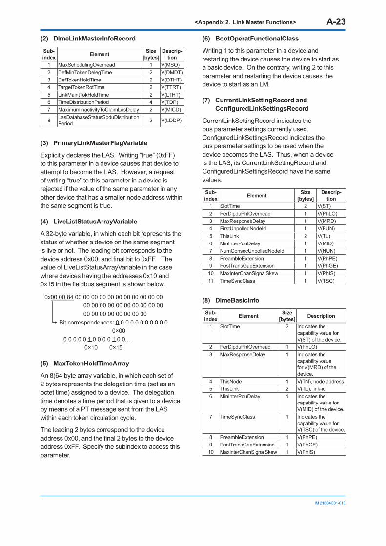
<Appendix 2. Link Master Functions> A-23
IM 21B04C01-01E
(2) DlmeLinkMasterInfoRecord
Sub-index Element Size
[bytes]Descrip-
tion1 MaxSchedulingOverhead 1 V(MSO)2 DefMinTokenDelegTime 2 V(DMDT)3 DefTokenHoldTime 2 V(DTHT)4 TargetTokenRotTime 2 V(TTRT)5 LinkMaintTokHoldTime 2 V(LTHT)6 TimeDistributionPeriod 4 V(TDP)7 MaximumInactivityToClaimLasDelay 2 V(MICD)
8 LasDatabaseStatusSpduDistributionPeriod 2 V(LDDP)
(3) PrimaryLinkMasterFlagVariable
Explicitly declares the LAS. Writing “true” (0xFF) to this parameter in a device causes that device to attempt to become the LAS. However, a request of writing “true” to this parameter in a device is rejected if the value of the same parameter in any other device that has a smaller node address within the same segment is true.
(4) LiveListStatusArrayVariable
A 32-byte variable, in which each bit represents the status of whether a device on the same segment is live or not. The leading bit corresponds to the device address 0x00, and final bit to 0xFF. The value of LiveListStatusArrayVariable in the case where devices having the addresses 0x10 and 0x15 in the fieldbus segment is shown below.
0x00 00 84 00 00 00 00 00 00 00 00 00 00 00 00 00 00 00 00 00 00 00 00 00 00 00 00 00 00 00 00 00 Bit correspondences: 0 0 0 0 0 0 0 0 0 0 0 0×00 0 0 0 0 0 1 0 0 0 0 1 0 0... 0×10 0×15
(5) MaxTokenHoldTimeArray
An 8(64 byte array variable, in which each set of 2 bytes represents the delegation time (set as an octet time) assigned to a device. The delegation time denotes a time period that is given to a device by means of a PT message sent from the LAS within each token circulation cycle.
The leading 2 bytes correspond to the device address 0x00, and the final 2 bytes to the device address 0xFF. Specify the subindex to access this parameter.
(6) BootOperatFunctionalClass
Writing 1 to this parameter in a device and restarting the device causes the device to start as a basic device. On the contrary, writing 2 to this parameter and restarting the device causes the device to start as an LM.
(7) CurrentLinkSettingRecord and ConfiguredLinkSettingsRecord
CurrentLinkSettingRecord indicates the bus parameter settings currently used. ConfiguredLinkSettingsRecord indicates the bus parameter settings to be used when the device becomes the LAS. Thus, when a device is the LAS, its CurrentLinkSettingRecord and ConfiguredLinkSettingsRecord have the same values.
Sub-index Element Size
[bytes]Descrip-
tion1 SlotTime 2 V(ST)2 PerDlpduPhlOverhead 1 V(PhLO)3 MaxResponseDelay 1 V(MRD)4 FirstUnpolledNodeId 1 V(FUN)5 ThisLink 2 V(TL)6 MinInterPduDelay 1 V(MID)7 NumConsecUnpolledNodeId 1 V(NUN)8 PreambleExtension 1 V(PhPE)9 PostTransGapExtension 1 V(PhGE)10 MaxInterChanSignalSkew 1 V(PhIS)11 TimeSyncClass 1 V(TSC)
(8) DlmeBasicInfo
Sub-index Element Size
[bytes] Description
1 SlotTime 2 Indicates the capability value for V(ST) of the device.
2 PerDlpduPhlOverhead 1 V(PhLO)3 MaxResponseDelay 1 Indicates the
capability value for V(MRD) of the device.
4 ThisNode 1 V(TN), node address5 ThisLink 2 V(TL), link-id6 MinInterPduDelay 1 Indicates the
capability value for V(MID) of the device.
7 TimeSyncClass 1 Indicates the capability value for V(TSC) of the device.
8 PreambleExtension 1 V(PhPE)9 PostTransGapExtension 1 V(PhGE)10 MaxInterChanSignalSkew 1 V(PhIS)
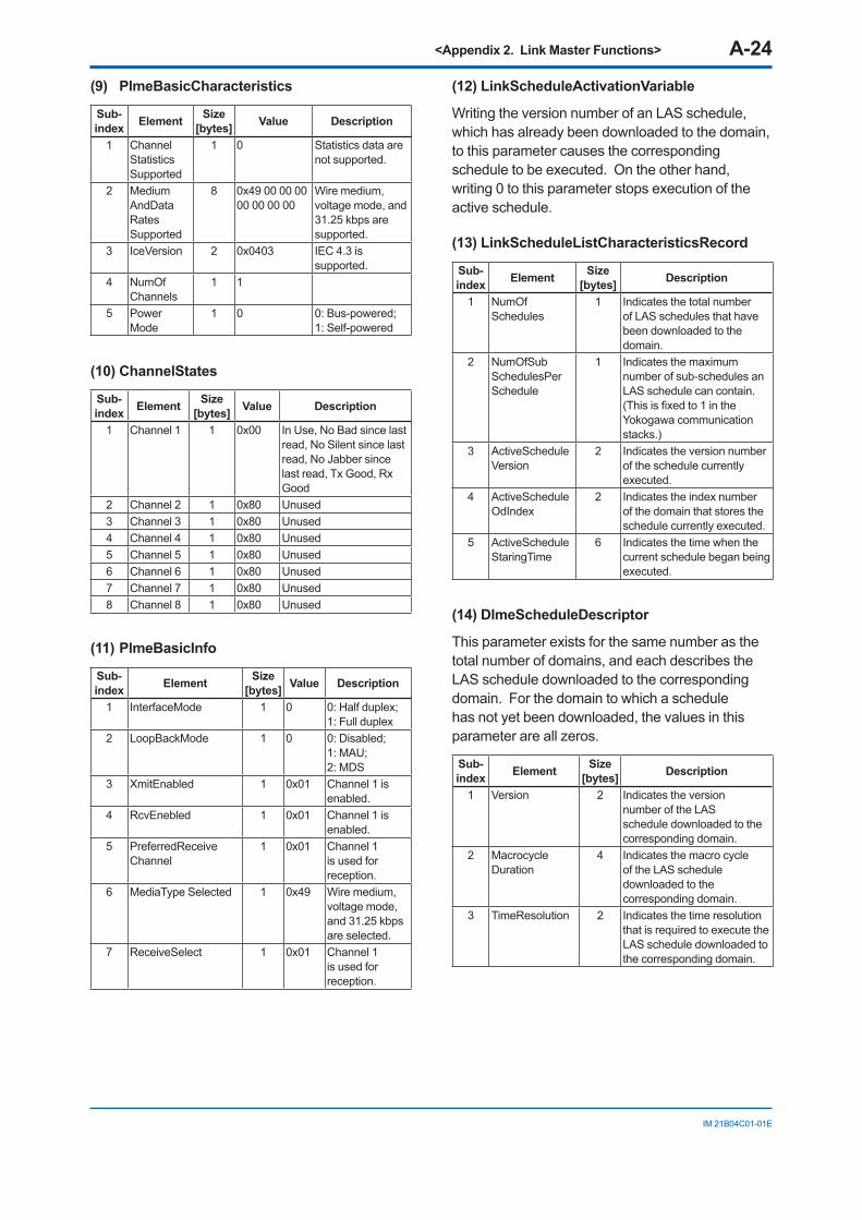
<Appendix 2. Link Master Functions> A-24
IM 21B04C01-01E
(9) PlmeBasicCharacteristics
Sub-index Element Size
[bytes] Value Description
1 Channel Statistics Supported
1 0 Statistics data are not supported.
2 Medium AndData Rates Supported
8 0x49 00 00 00 00 00 00 00
Wire medium, voltage mode, and 31.25 kbps are supported.
3 IceVersion 2 0x0403 IEC 4.3 is supported.
4 NumOf Channels
1 1
5 Power Mode
1 0 0: Bus-powered; 1: Self-powered
(10) ChannelStates
Sub-index Element Size
[bytes] Value Description
1 Channel 1 1 0x00 In Use, No Bad since last read, No Silent since last read, No Jabber since last read, Tx Good, Rx Good
2 Channel 2 1 0x80 Unused3 Channel 3 1 0x80 Unused4 Channel 4 1 0x80 Unused5 Channel 5 1 0x80 Unused6 Channel 6 1 0x80 Unused7 Channel 7 1 0x80 Unused8 Channel 8 1 0x80 Unused
(11) PlmeBasicInfo
Sub-index Element Size
[bytes] Value Description
1 InterfaceMode 1 0 0: Half duplex; 1: Full duplex
2 LoopBackMode 1 0 0: Disabled; 1: MAU; 2: MDS
3 XmitEnabled 1 0x01 Channel 1 is enabled.
4 RcvEnebled 1 0x01 Channel 1 is enabled.
5 PreferredReceive Channel
1 0x01 Channel 1 is used for reception.
6 MediaType Selected 1 0x49 Wire medium, voltage mode, and 31.25 kbps are selected.
7 ReceiveSelect 1 0x01 Channel 1 is used for reception.
(12) LinkScheduleActivationVariable
Writing the version number of an LAS schedule, which has already been downloaded to the domain, to this parameter causes the corresponding schedule to be executed. On the other hand, writing 0 to this parameter stops execution of the active schedule.
(13) LinkScheduleListCharacteristicsRecord
Sub-index Element Size
[bytes] Description
1 NumOf Schedules
1 Indicates the total number of LAS schedules that have been downloaded to the domain.
2 NumOfSub SchedulesPer Schedule
1 Indicates the maximum number of sub-schedules an LAS schedule can contain. (This is fixed to 1 in the Yokogawa communication stacks.)
3 ActiveSchedule Version
2 Indicates the version number of the schedule currently executed.
4 ActiveSchedule OdIndex
2 Indicates the index number of the domain that stores the schedule currently executed.
5 ActiveSchedule StaringTime
6 Indicates the time when the current schedule began being executed.
(14) DlmeScheduleDescriptor
This parameter exists for the same number as the total number of domains, and each describes the LAS schedule downloaded to the corresponding domain. For the domain to which a schedule has not yet been downloaded, the values in this parameter are all zeros.
Sub-index Element Size
[bytes] Description
1 Version 2 Indicates the version number of the LAS schedule downloaded to the corresponding domain.
2 Macrocycle Duration
4 Indicates the macro cycle of the LAS schedule downloaded to the corresponding domain.
3 TimeResolution 2 Indicates the time resolution that is required to execute the LAS schedule downloaded to the corresponding domain.
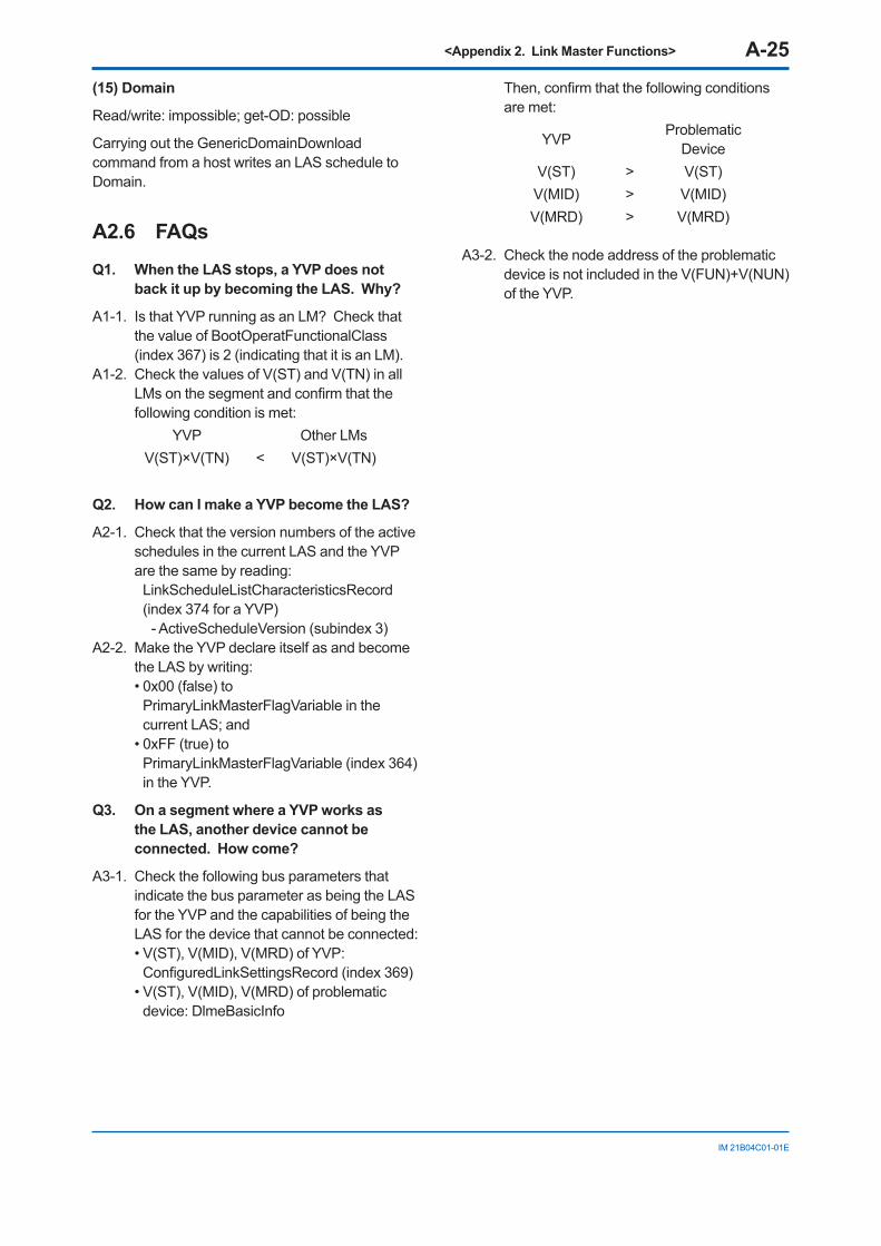
<Appendix 2. Link Master Functions> A-25
IM 21B04C01-01E
(15) Domain
Read/write: impossible; get-OD: possible
Carrying out the GenericDomainDownload command from a host writes an LAS schedule to Domain.
A2.6 FAQsQ1. When the LAS stops, a YVP does not
back it up by becoming the LAS. Why?
A1-1. Is that YVP running as an LM? Check that the value of BootOperatFunctionalClass (index 367) is 2 (indicating that it is an LM).
A1-2. Check the values of V(ST) and V(TN) in all LMs on the segment and confirm that the following condition is met:
YVP Other LMsV(ST)×V(TN) < V(ST)×V(TN)
Q2. How can I make a YVP become the LAS?
A2-1. Check that the version numbers of the active schedules in the current LAS and the YVP are the same by reading:
LinkScheduleListCharacteristicsRecord (index 374 for a YVP)
- ActiveScheduleVersion (subindex 3)A2-2. Make the YVP declare itself as and become
the LAS by writing: • 0x00 (false) to
PrimaryLinkMasterFlagVariable in the current LAS; and
• 0xFF (true) to PrimaryLinkMasterFlagVariable (index 364) in the YVP.
Q3. On a segment where a YVP works as the LAS, another device cannot be connected. How come?
A3-1. Check the following bus parameters that indicate the bus parameter as being the LAS for the YVP and the capabilities of being the LAS for the device that cannot be connected:
• V(ST), V(MID), V(MRD) of YVP: ConfiguredLinkSettingsRecord (index 369)
• V(ST), V(MID), V(MRD) of problematic device: DlmeBasicInfo
Then, confirm that the following conditions are met:
YVP ProblematicDevice
V(ST) > V(ST)V(MID) > V(MID)V(MRD) > V(MRD)
A3-2. Check the node address of the problematic device is not included in the V(FUN)+V(NUN) of the YVP.
<Appendix 3. DD Methods and DD Menu> A-26
IM 21B04C01-01E
Appendix 3. DD Methods and DD MenuA3.1 OverviewFieldbus technology has enabled a broad range of functions to be covered by a field device alone. Conversely, it has resulted in increased parameters to support these increased functions. To alleviate intricate operations due to the multiplied parameters and to provide easier-to-use user interfaces, fieldbus technology offers a menu facility and interactive guidance facility called methods, to be incorporated in device descriptions (DDs). With a field device whose DD contains a pre-embedded menu and methods, users can easily and intuitively access desired parameters and perform a series of setup operations.
A DD menu and DD methods are features embedded in a DD file for a field device, therefore, software supporting them needs to be used on the host computer for fieldbus system configuration. Make an inquiry to the software supplier about whether and how the software you use supports DD menus and DD methods. This User’s Manual describes only the DD menu and DD methods of the YVP110.
A3.2 DD Methods DD methods guide you in setting parameter procedures properly. Simply following instructions given by DD methods will accomplish the intended parameter setting without accessing a wrong parameter or failing to follow the correct setting procedure. Note that in principle, accessing the individual parameters can also make the settings that can be made using DD methods.
As for the YVP110, twelve DD methods for the transducer block, two for the AO block, and one for the OS block are provided. The following describes these methods for each block model.
A3.2.1 Transducer Block
1) Setup Wizard
This method guides you through each step of the most common setup procedure that always needs to be performed after installing the YVP110 on a valve. For the details of the setup and pertaining parameters, see Chapter 5, “Setup.”
Setup procedure• AO/TB block mode check• ACT_FAIL_ACTION setting• VALVE_TYPE setting• Stop position search and automatic tuning• Travel calibration
0% calibration Span calibration 50% calibration
• Operational parameter setting • …
2) Auto Tuning Wizard
This method guides you through each step to search for the valve’s mechanical stop positions and carry out auto tuning of control parameters. For details, see Section 5.3, “Carrying out Auto Tuning.”
Auto tuning procedure• AO/TB block mode check• Auto tuning execution: AUTO_TUNE_EXEC
3) Search Stop Points
This method guides you through each step to search for the valve’s mechanical stop positions (both on the closed and open sides) by maximizing and minimizing the output pressure to the positioner.
Setup procedure• AO/TB block mode check• Auto tuning execution: AUTO_TUNE_EXEC
Standard Without timeout Step by step Exit
4) Control Parameter Tuning
This method helps perform control-parameter-specific tuning, from among the parameters that can be tuned by the auto tuning function. It does not contain a help utility for a stop point search (searching for the valve’s mechanical stop positions).
• AO/TB block mode check• Execution of control parameter tuning:
AUTO_TUNE_EXEC
<Appendix 3. DD Methods and DD Menu> A-27
IM 21B04C01-01E
5) Travel Calibration
This method guides you through each step to carry out travel calibration. See the respective descriptions in Section 5.3, “Carrying out Auto Tuning.”
Travel calibration procedure• AO/Transducer block mode check• Execute travel calibration
0% calibration: Adjustment of FINAL_VALUE (by moving the valve position to the desired 0% position) Execute 0% calibration: TRAVEL_CALIB_EXEC
Span calibration: Adjustment of FINAL_VALUE (by moving the valve position to the desired 100% position) Execute span calibration: TRAVEL_CALIB_EXEC
50% calibration: Adjustment of FINAL_VALUE (by moving the valve position to the desired 50% position) Execute 50% calibration: TRAVEL_CALIB_EXEC
Exit
6) Operational Parameter Configuration
This method guides you through the setting of individual operational parameters excluding the selection of position-to-flow rate characteristic type.
Operational parameter configuration procedure• AO/Transducer block mode check• Operational parameter configuration
Position Limit setting: FINAL_VALUE_CUTOFF_LO FINAL_VALUE_CUTOFF_HIFINAL_VALUE_RANGE
Limit Switch setting: LIM_SW_LO_LIMLIM_SW_HI_LIM
Fault Control:DEVIATION_LIM DEVIATION_TIME_TH(1)DEVIATION_TIME_TH(2)
Others: NEAR_CLOSE_THRESHOLD
Exit
7) Release Fail Safe
This is a method for releasing the device latched by the fail-safe actions, restoring it to the normal state.
Procedure of releasing fail safe • Check whether the device is in the latched
state. • Write “Clear-latched” to parameter RELEASE_
FAIL_SAFE if the device is in the latched state, to release it from the latched state.
8) Instant Trouble Shooting
This is a help utility which provides troubleshooting instructions such as indicating the points and parameters to be checked for troubleshooting. This method does not contain a utility to change parameter settings. For troubleshooting of device statuses, see Chapter 18, “Troubleshooting.”
Instant troubleshooting procedure• Commanded to check DEVICE_STATUS in the
resource block • Check XD_ERROR and the remedy will be
displayed if an error has been detected• Check RELEASE_FAIL_SAFE• Commanded to check the mechanical linkage,
piping, and installation conditions• Commanded to check the correct operation of
the device hardware
9) Self Check Execution
The self-check measures the valve’s characteristics in the same fashion as in auto tuning, and makes no changes to parameter settings.
Self Check Execution procedure• AO/TB block mode check• Self check execution: AUTO_TUNE_EXEC
10) Signature Execution
This method guides you through each step to perform signature measurement (see Chapter 17, “Diagnostics”). Signature measurement entails off-line diagnostics functions to measure characteristics of the valve and positioner. Comparing the current signature data with the previously measured data gives clues to identify the deterioration status and a possible need of maintenance.
<Appendix 3. DD Methods and DD Menu> A-28
IM 21B04C01-01E
Signature execution procedure• AO/TB block mode check• Signature measurement execution
Measure all: Setting all signature measurement conditions Executing signature measurement (SIGN_MEAS_EXEC)Uploading data (see Item 11) below).
Measure actuator signature: Setting STD_ACT_SIGN_SET Executing signature measurement (SIGN_MEAS_EXEC)Uploading data (see Item 11) below).
Measure extended actuator signature: Setting EXT_ACT_SIGN_SET Executing signature measurement (SIGN_MEAS_EXEC)Uploading data (see Item 11) below).
Step response test: Setting STEP_RESP_SET Executing step response test (SIGN_MEAS_EXEC)Uploading data (see Item 11) below).
Measure positioner signature: Setting POSITIONER_SIGN_SET Executing signature measurement (SIGN_MEAS_EXEC)Uploading data (see Item 11) below).
Exit
11) Upload Signature Data
This method guides you through uploading the signature data that has been measured and stored in the positioner, from selecting the database you want to upload, to adjusting the data pointer to the leading position of the desired data and uploading it.
Signature data uploading procedure• Select action from menu
Upload data: Uploading data from SIGN_DATA_X and SIGN_DATA_Y
Select upload database (meaning, “select the database to be uploaded”)
Change data pointer Exit
12) Upload Signature Header Data
This method guides you through uploading the header data of a signature measurement that has already been performed. The header data contains the measurement condition settings, the ambient temperature at the measurement, the date of the measurement, and so on. Users can select a database to access the desired header data.
Signature header data uploading procedure• Selection of action from menu
Upload header data: Select upload database (meaning, “select
the database to be uploaded”) Exit
A3.2.2 AO Block
1) Simulation Enable
This is a method for causing the AO block to activate the simulation status. When a block is in the simulation status, you can apply simulated inputs to the block to let the block function with that input, and check the actions of the function block application and alarm processing. Since the simulation function is disabled to run normally in consideration of the nature of its functionality, when using this method, the simulation function needs to be rendered active by doing either of the following:
• Write “REMOTE LOOP TEST SWITCH” to SIM_ENABLE_MSG in the resource block.
• Turn on the SIM.ENABLE hardware switch on the YPV110’s amplifier assembly (see Section 10.3, “Simulation Function”).
Simulation enabling procedure• Check that the simulation switch is ON (active). • Check the AO block mode • Change the value of SIMULATE.status to
“Enable” • Set the simulated input value in SIMULATE.
value
2) Simulation Disable
This is a method for disabling the simulation function of the AO block.
Simulation disabling procedure• Confirm whether the simulation function can be
disabled. • Change the value of SIMULATE.status to
“Disable”
<Appendix 3. DD Methods and DD Menu> A-29
IM 21B04C01-01E
• The method displays a message announcing that block alarms will not be reset until both the hardware switch and software switch in the resource block for enabling execution of the simulation function are turned off.
A3.2.3 OS Block
1) X-Y Scaling
This is a method for setting the scales of the X- and Y-axes for defining the conversion characteristics for OUT_1 and OUT_2 (values of IN_ARRAY and OUT_ARRAY), by setting the coordinates of four endpoints: P1 as the start point of OUT_1, P2 as the end point of OUT_1, P3 as the start point of OUT_2, and P4 as the end point of OUT_2. (See also Section 15.3, “Output Processing.”)
X-Y scaling procedure• Set coordinates of P1 through P4
P1: IN_ARRAY, OUT_ARRAY P2: IN_ARRAY, OUT_ARRAY P3: IN_ARRAY, OUT_ARRAY P4: IN_ARRAY, OUT_ARRAY
• Set LOCK_VAL
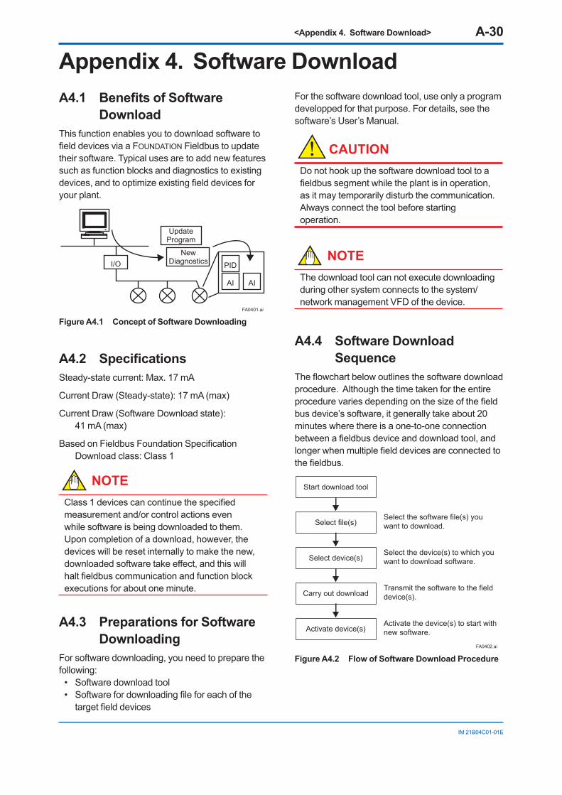
<Appendix 4. Software Download> A-30
IM 21B04C01-01E
Appendix 4. Software DownloadA4.1 Benefits of Software
DownloadThis function enables you to download software to field devices via a FOUNDATION Fieldbus to update their software. Typical uses are to add new features such as function blocks and diagnostics to existing devices, and to optimize existing field devices for your plant.
FA0401.ai
PID
AI AI
Update Program
New DiagnosticsI/O
Figure A4.1 Concept of Software Downloading
A4.2 SpecificationsSteady-state current: Max. 17 mA
Current Draw (Steady-state): 17 mA (max)
Current Draw (Software Download state): 41 mA (max)
Based on Fieldbus Foundation Specification Download class: Class 1
NOTEClass 1 devices can continue the specified measurement and/or control actions even while software is being downloaded to them. Upon completion of a download, however, the devices will be reset internally to make the new, downloaded software take effect, and this will halt fieldbus communication and function block executions for about one minute.
A4.3 Preparations for Software Downloading
For software downloading, you need to prepare the following:
• Software download tool• Software for downloading file for each of the
target field devices
For the software download tool, use only a program developped for that purpose. For details, see the software’s User’s Manual.
CAUTIONDo not hook up the software download tool to a fieldbus segment while the plant is in operation, as it may temporarily disturb the communication. Always connect the tool before starting operation.
NOTEThe download tool can not execute downloading during other system connects to the system/network management VFD of the device.
A4.4 Software Download Sequence
The flowchart below outlines the software download procedure. Although the time taken for the entire procedure varies depending on the size of the field bus device’s software, it generally take about 20 minutes where there is a one-to-one connection between a fieldbus device and download tool, and longer when multiple field devices are connected to the fieldbus.
FA0402.ai
Start download tool
Select file(s)
Select device(s)
Carry out download
Activate device(s)
Select the software file(s) you want to download.
Select the device(s) to which you want to download software.
Transmit the software to the field device(s).
Activate the device(s) to start with new software.
Figure A4.2 Flow of Software Download Procedure
<Appendix 4. Software Download> A-31
IM 21B04C01-01E
CAUTIONCarrying out a software download leaves the PD tag, node address, and transducer block calibration parameters that are retained in the nonvolatile memory inside the target device, but may reset other parameters to the defaults (except a minor update that does not change the number of parameters). Hence, where necessary, save the parameters using an engineering tool, parameter setting utility, or the like before carrying out a software download, and then reconfigure the field device(s) after the download. For details, see Section A4.6.
CAUTIONThe current dissipation of the target field device increases transitorily immediately after a download due to erasing of the FlashROM’s contents. Use a fieldbus power supply which has sufficient capacity to cover such increases in feed current.
CAUTIONUpon completion of the activation, the target fieldbus device performs resetting internally, which temporarily halts fieldbus communication and function block executions. Be especially careful about a valve positioner; the output air pressure will fall to the minimum level (i.e., zero).
CAUTIONDo not turn off the power to a field device or disconnect the download tool during a download or activation. The device may fail as a result.
NOTEBe careful about the noise on the fieldbus link. If the fieldbus is noisy, the downloading may take a very long time or fail.
A4.5 Download FilesDownload files have the following filenames (with the filename extension of “.ffd”). Take care to choose the correct download file for the target field device:
“594543” + device family + “_” + device type + “_” + domain name + “_” + software name + “_” + software revision + “.ffd”
For example, the name of the download file for an YVP may have the following name:
594543000C_0007_YVP_ORIGINAL_R101.ffd
Refer to A4.10(3) DOMAIN_HEADER about each keyword of the file name.
The device type is “0007” for an YVP transmitter .
The software name is “ORIGINAL” or “UPDATE.” The former indicates an original file and the latter an update file. Whenever performing a download to update the device revision, obtain the original file. In general, an addition to the parameters or blocks requires a device revision update.
A4.6 Steps after Activating a Field Device
When the communication with a field device has recovered after activating the device, check using the download tool that the software revision of the field device has been updated accordingly. The value of SOFT_REV of the resource block indicates the software revision.
The PD tag, node address, and transducer block calibration parameters that are retained in the nonvolatile memory inside the target device will remain unchanged after a software download. However, after a software update which causes an addition to the block parameters or blocks, or to the system/network management VFD parameters, some parameters may be reset to the defaults, thus requiring parameter setup and engineering again. For details, see the table below.
Also note that a change in the number of parameters or blocks requires the DD and capabilities files corresponding to the new software revision.
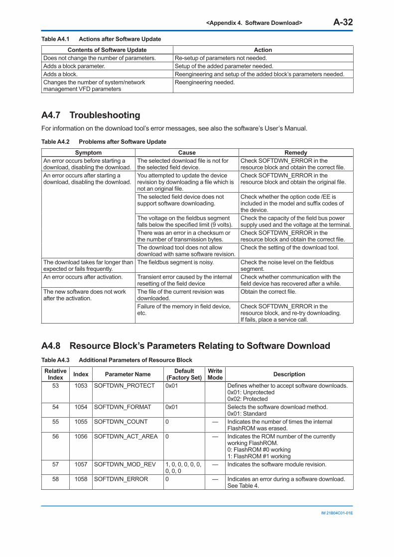
<Appendix 4. Software Download> A-32
IM 21B04C01-01E
Table A4.1 Actions after Software Update
Contents of Software Update ActionDoes not change the number of parameters. Re-setup of parameters not needed.Adds a block parameter. Setup of the added parameter needed.Adds a block. Reengineering and setup of the added block’s parameters needed.Changes the number of system/network management VFD parameters
Reengineering needed.
A4.7 TroubleshootingFor information on the download tool’s error messages, see also the software’s User’s Manual.
Table A4.2 Problems after Software Update
Symptom Cause RemedyAn error occurs before starting a download, disabling the download.
The selected download file is not for the selected field device.
Check SOFTDWN_ERROR in the resource block and obtain the correct file.
An error occurs after starting a download, disabling the download.
You attempted to update the device revision by downloading a file which is not an original file.
Check SOFTDWN_ERROR in the resource block and obtain the original file.
The selected field device does not support software downloading.
Check whether the option code /EE is included in the model and suffix codes of the device.
The voltage on the fieldbus segment falls below the specified limit (9 volts).
Check the capacity of the field bus power supply used and the voltage at the terminal.
There was an error in a checksum or the number of transmission bytes.
Check SOFTDWN_ERROR in the resource block and obtain the correct file.
The download tool does not allow download with same software revision.
Check the setting of the download tool.
The download takes far longer than expected or fails frequently.
The fieldbus segment is noisy. Check the noise level on the fieldbus segment.
An error occurs after activation. Transient error caused by the internal resetting of the field device
Check whether communication with the field device has recovered after a while.
The new software does not work after the activation.
The file of the current revision was downloaded.
Obtain the correct file.
Failure of the memory in field device, etc.
Check SOFTDWN_ERROR in the resource block, and re-try downloading. If fails, place a service call.
A4.8 Resource Block’s Parameters Relating to Software DownloadTable A4.3 Additional Parameters of Resource Block
Relative Index Index Parameter Name Default
(Factory Set)Write Mode Description
53 1053 SOFTDWN_PROTECT 0x01 Defines whether to accept software downloads.0x01: Unprotected 0x02: Protected
54 1054 SOFTDWN_FORMAT 0x01 Selects the software download method. 0x01: Standard
55 1055 SOFTDWN_COUNT 0 — Indicates the number of times the internal FlashROM was erased.
56 1056 SOFTDWN_ACT_AREA 0 — Indicates the ROM number of the currently working FlashROM. 0: FlashROM #0 working 1: FlashROM #1 working
57 1057 SOFTDWN_MOD_REV 1, 0, 0, 0, 0, 0, 0, 0, 0
— Indicates the software module revision.
58 1058 SOFTDWN_ERROR 0 — Indicates an error during a software download. See Table 4.
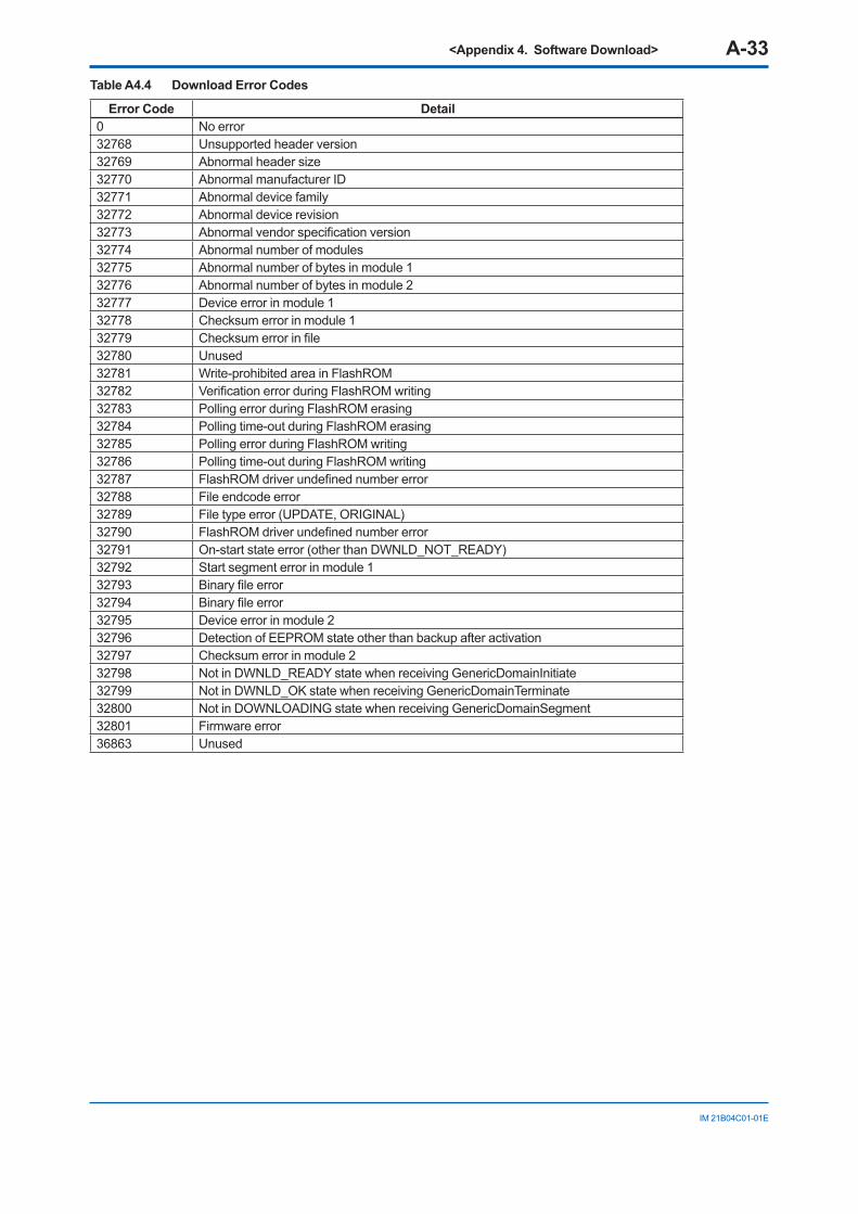
<Appendix 4. Software Download> A-33
IM 21B04C01-01E
Table A4.4 Download Error Codes
Error Code Detail0 No error32768 Unsupported header version32769 Abnormal header size32770 Abnormal manufacturer ID32771 Abnormal device family32772 Abnormal device revision32773 Abnormal vendor specification version32774 Abnormal number of modules32775 Abnormal number of bytes in module 132776 Abnormal number of bytes in module 232777 Device error in module 132778 Checksum error in module 132779 Checksum error in file32780 Unused32781 Write-prohibited area in FlashROM32782 Verification error during FlashROM writing32783 Polling error during FlashROM erasing32784 Polling time-out during FlashROM erasing32785 Polling error during FlashROM writing32786 Polling time-out during FlashROM writing32787 FlashROM driver undefined number error32788 File endcode error32789 File type error (UPDATE, ORIGINAL)32790 FlashROM driver undefined number error32791 On-start state error (other than DWNLD_NOT_READY)32792 Start segment error in module 132793 Binary file error32794 Binary file error32795 Device error in module 232796 Detection of EEPROM state other than backup after activation32797 Checksum error in module 232798 Not in DWNLD_READY state when receiving GenericDomainInitiate32799 Not in DWNLD_OK state when receiving GenericDomainTerminate32800 Not in DOWNLOADING state when receiving GenericDomainSegment32801 Firmware error36863 Unused
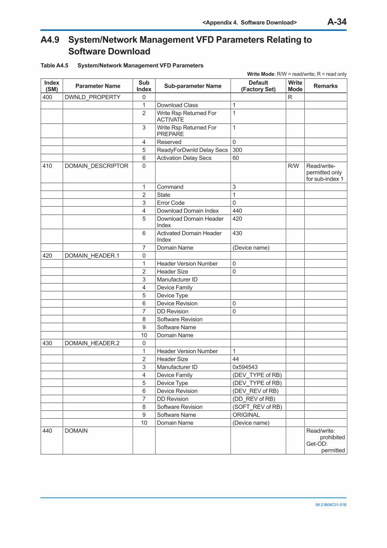
<Appendix 4. Software Download> A-34
IM 21B04C01-01E
A4.9 System/Network Management VFD Parameters Relating to Software Download
Table A4.5 System/Network Management VFD ParametersWrite Mode: R/W = read/write; R = read only
Index (SM) Parameter Name Sub
Index Sub-parameter Name Default (Factory Set)
Write Mode Remarks
400 DWNLD_PROPERTY 0 R1 Download Class 12 Write Rsp Returned For
ACTIVATE1
3 Write Rsp Returned For PREPARE
1
4 Reserved 05 ReadyForDwnld Delay Secs 3006 Activation Delay Secs 60
410 DOMAIN_DESCRIPTOR 0 R/W Read/write-permitted only for sub-index 1
1 Command 32 State 13 Error Code 04 Download Domain Index 4405 Download Domain Header
Index420
6 Activated Domain Header Index
430
7 Domain Name (Device name)420 DOMAIN_HEADER.1 0
1 Header Version Number 02 Header Size 03 Manufacturer ID4 Device Family5 Device Type6 Device Revision 07 DD Revision 08 Software Revision9 Software Name10 Domain Name
430 DOMAIN_HEADER.2 01 Header Version Number 12 Header Size 443 Manufacturer ID 0x5945434 Device Family (DEV_TYPE of RB)5 Device Type (DEV_TYPE of RB)6 Device Revision (DEV_REV of RB)7 DD Revision (DD_REV of RB)8 Software Revision (SOFT_REV of RB)9 Software Name ORIGINAL10 Domain Name (Device name)
440 DOMAIN Read/write: prohibited
Get-OD: permitted

<Appendix 4. Software Download> A-35
IM 21B04C01-01E
A4.10 Comments on System/Network Management VFD Parameters Relating to Software Download
IMPORTANTDo not turn off the power to a field device immediately after changing parameter settings. Data writing actions to the EEPROM are dual redandant to ensure reliability. If the power is turned off within 60 seconds after setup, the parameters may revert to the previous settings.
(1) DWNLD_PROPERTY
Sub Index Element Size
(Bytes) Description
1 Download Class 1 Indicates the download class. 1: Class 1
2 Write Rsp Returned For ACTIVATE
1 Indicates whether a write response is returned to the ACTIVATE command. 1: Write Response Returned
3 Write Rsp Returned For PREPARE
1 Indicates whether a write response is returned to the PREPARE command. 1: Write Response Returned
4 Reserved 1 (Reserved)5 ReadyForDwnld Delay
Secs2 Indicates the maximum delay after receipt of the PREPARE_FOR_
DWNLD command to proceed to transition from DWNLD_NOT_READY to DWNLD_READY.
6 Activation Delay Secs 2 Indicates the maximum delay after receipt of the ACTIVATE command to proceed to transition from DWNLD_OK to DWNLD_NOT_READY.
(2) DOMAIN_DESCRIPTOR
Sub Index Element Size
(Bytes) Description
1 Command 1 Reads/writes software download commands. 1: PREPARE_FOR_DWNLD (instruction of download preparation) 2: ACTIVATE (activation instruction) 3: CANCEL_DWNLD (instruction of download cancellation)
2 State 1 Indicates the current download status. 1: DWNLD_NOT_READY (download not ready) 2: DWNLD_PREPARING (download under preparation) 3: DWNLD_READY (ready for download) 4:DWNLD_OK (download complete) 5: DOWNLOADING (download underway) 6: CHECKSUM_FAIL (not used in this product) 7: FMS_DOWNLOAD_FAIL (failure during download) 8: DWNLD_INCOMPLETE (download error detected at restart) 9: VCR_FAIL (not used in this product) 10: OTHER (download error other than 6 and 7 detected)
3 Error Code 2 Indicates the error during a download and activation. 0: success, configuration retained (download successfully completed) 32768 - 65535: Download error (See Table 4 for error codes.)
4 Download Domain Index 4 Indicates the index number of the domain for software downloading.5 Download Domain Header
Index4 Indicates the index number of the domain header to which the download
is performing.6 Activated Domain Header
Index4 Indicates the index numbers of the domain header currently running.
7 Domain Name 8 Indicates the domain name. With this product, Domain Name indicates the field device name.
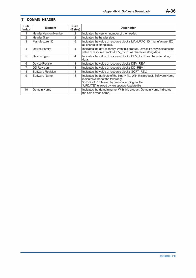
<Appendix 4. Software Download> A-36
IM 21B04C01-01E
(3) DOMAIN_HEADER
Sub Index Element Size
(Bytes) Description
1 Header Version Number 2 Indicates the version number of the header.2 Header Size 2 Indicates the header size.3 Manufacturer ID 6 Indicates the value of resource block’s MANUFAC_ID (manufacturer ID)
as character string data.4 Device Family 4 Indicates the device family. With this product, Device Family indicates the
value of resource block’s DEV_TYPE as character string data.5 Device Type 4 Indicates the value of resource block’s DEV_TYPE as character string
data.6 Device Revision 1 Indicates the value of resource block’s DEV_REV.7 DD Revision 1 Indicates the value of resource block’s DD_REV.8 Software Revision 8 Indicates the value of resource block’s SOFT_REV.9 Software Name 8 Indicates the attribute of the binary file. With this product, Software Name
indicates either of the following: “ORIGINAL” followed by one space: Original file “UPDATE” followed by two spaces: Update file
10 Domain Name 8 Indicates the domain name. With this product, Domain Name indicates the field device name.
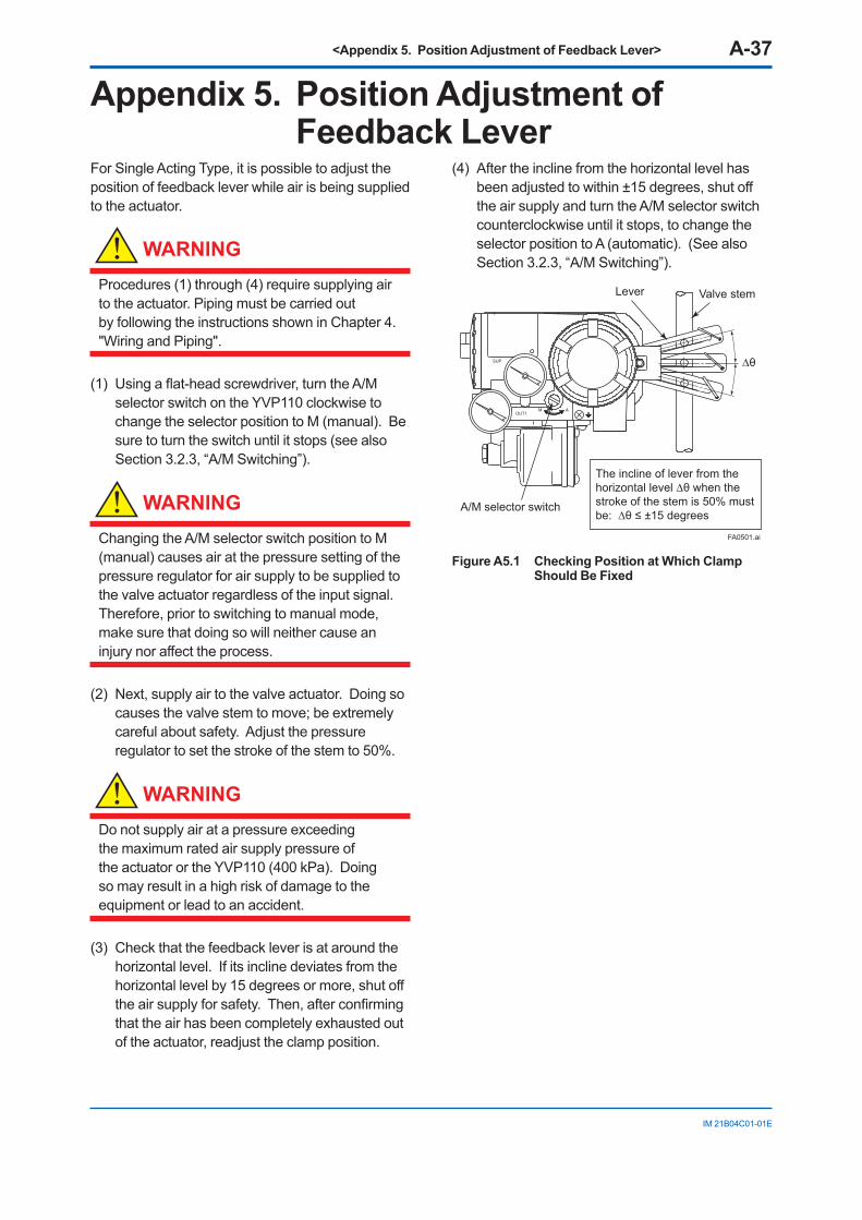
<Appendix 5. Position Adjustment of Feedback Lever> A-37
IM 21B04C01-01E
Appendix 5. Position Adjustment of Feedback Lever
For Single Acting Type, it is possible to adjust the position of feedback lever while air is being supplied to the actuator.
WARNING
Procedures (1) through (4) require supplying air to the actuator. Piping must be carried out by following the instructions shown in Chapter 4. "Wiring and Piping".
(1) Using a flat-head screwdriver, turn the A/M selector switch on the YVP110 clockwise to change the selector position to M (manual). Be sure to turn the switch until it stops (see also Section 3.2.3, “A/M Switching”).
WARNING
Changing the A/M selector switch position to M (manual) causes air at the pressure setting of the pressure regulator for air supply to be supplied to the valve actuator regardless of the input signal. Therefore, prior to switching to manual mode, make sure that doing so will neither cause an injury nor affect the process.
(2) Next, supply air to the valve actuator. Doing so causes the valve stem to move; be extremely careful about safety. Adjust the pressure regulator to set the stroke of the stem to 50%.
WARNING
Do not supply air at a pressure exceeding the maximum rated air supply pressure of the actuator or the YVP110 (400 kPa). Doing so may result in a high risk of damage to the equipment or lead to an accident.
(3) Check that the feedback lever is at around the horizontal level. If its incline deviates from the horizontal level by 15 degrees or more, shut off the air supply for safety. Then, after confirming that the air has been completely exhausted out of the actuator, readjust the clamp position.
(4) After the incline from the horizontal level has been adjusted to within ±15 degrees, shut off the air supply and turn the A/M selector switch counterclockwise until it stops, to change the selector position to A (automatic). (See also Section 3.2.3, “A/M Switching”).
FA0501.ai
Valve stemLever
A/M selector switch
∆θ
The incline of lever from the horizontal level ∆θ when the stroke of the stem is 50% must be: ∆θ ≤ ±15 degrees
Figure A5.1 Checking Position at Which Clamp Should Be Fixed
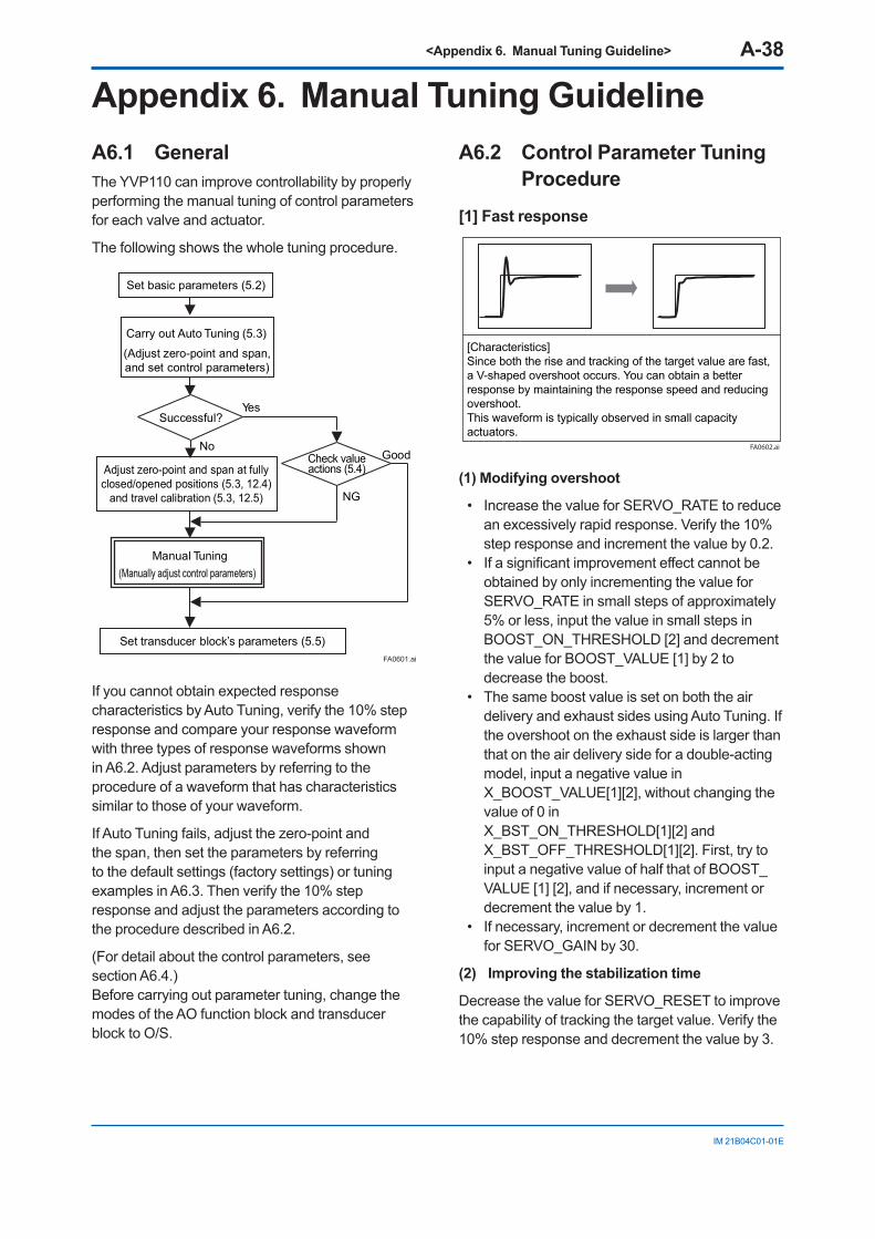
<Appendix 6. Manual Tuning Guideline> A-38
IM 21B04C01-01E
Appendix 6. Manual Tuning GuidelineA6.1 GeneralThe YVP110 can improve controllability by properly performing the manual tuning of control parameters for each valve and actuator.
The following shows the whole tuning procedure.
Manual Tuning(Manually adjust control parameters)
Check valueactions (5.4)
Carry out Auto Tuning (5.3)
(Adjust zero-point and span,and set control parameters)
Successful?Yes
No
NG
Adjust zero-point and span at fullyclosed/opened positions (5.3, 12.4)
and travel calibration (5.3, 12.5)
Set basic parameters (5.2)
Set transducer block’s parameters (5.5)
Good
FA0601.ai
If you cannot obtain expected response characteristics by Auto Tuning, verify the 10% step response and compare your response waveform with three types of response waveforms shown in A6.2. Adjust parameters by referring to the procedure of a waveform that has characteristics similar to those of your waveform.
If Auto Tuning fails, adjust the zero-point and the span, then set the parameters by referring to the default settings (factory settings) or tuning examples in A6.3. Then verify the 10% step response and adjust the parameters according to the procedure described in A6.2.
(For detail about the control parameters, see section A6.4.) Before carrying out parameter tuning, change the modes of the AO function block and transducer block to O/S.
A6.2 Control Parameter Tuning Procedure
[1] Fast response
[Characteristics] Since both the rise and tracking of the target value are fast, a V-shaped overshoot occurs. You can obtain a better response by maintaining the response speed and reducing overshoot. This waveform is typically observed in small capacity actuators.
FA0602.ai
(1) Modifying overshoot
• Increase the value for SERVO_RATE to reduce an excessively rapid response. Verify the 10% step response and increment the value by 0.2.
• If a significant improvement effect cannot be obtained by only incrementing the value for SERVO_RATE in small steps of approximately 5% or less, input the value in small steps in BOOST_ON_THRESHOLD [2] and decrement the value for BOOST_VALUE [1] by 2 to decrease the boost.
• The same boost value is set on both the air delivery and exhaust sides using Auto Tuning. If the overshoot on the exhaust side is larger than that on the air delivery side for a double-acting model, input a negative value in X_BOOST_VALUE[1][2], without changing the value of 0 in X_BST_ON_THRESHOLD[1][2] and X_BST_OFF_THRESHOLD[1][2]. First, try to input a negative value of half that of BOOST_VALUE [1] [2], and if necessary, increment or decrement the value by 1.
• If necessary, increment or decrement the value for SERVO_GAIN by 30.
(2) Improving the stabilization time
Decrease the value for SERVO_RESET to improve the capability of tracking the target value. Verify the 10% step response and decrement the value by 3.
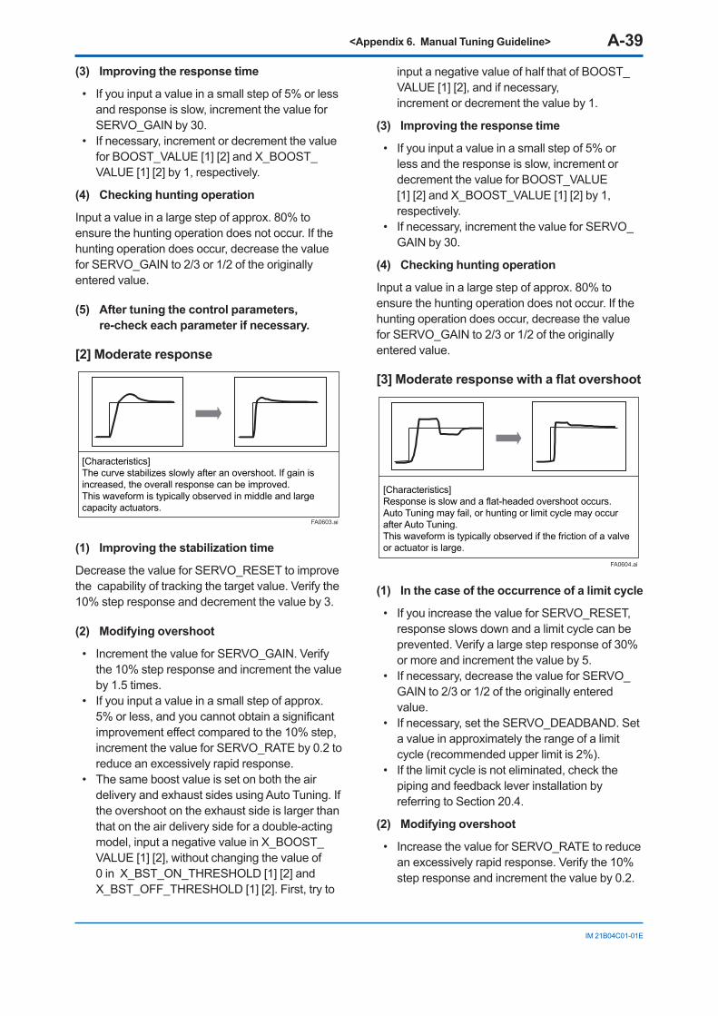
<Appendix 6. Manual Tuning Guideline> A-39
IM 21B04C01-01E
(3) Improving the response time
• If you input a value in a small step of 5% or less and response is slow, increment the value for SERVO_GAIN by 30.
• If necessary, increment or decrement the value for BOOST_VALUE [1] [2] and X_BOOST_VALUE [1] [2] by 1, respectively.
(4) Checking hunting operation
Input a value in a large step of approx. 80% to ensure the hunting operation does not occur. If the hunting operation does occur, decrease the value for SERVO_GAIN to 2/3 or 1/2 of the originally entered value.
(5) After tuning the control parameters, re-check each parameter if necessary.
[2] Moderate response
[Characteristics]The curve stabilizes slowly after an overshoot. If gain is increased, the overall response can be improved.This waveform is typically observed in middle and large capacity actuators.
FA0603.ai
(1) Improving the stabilization time
Decrease the value for SERVO_RESET to improve the capability of tracking the target value. Verify the 10% step response and decrement the value by 3.
(2) Modifying overshoot
• Increment the value for SERVO_GAIN. Verify the 10% step response and increment the value by 1.5 times.
• If you input a value in a small step of approx. 5% or less, and you cannot obtain a significant improvement effect compared to the 10% step, increment the value for SERVO_RATE by 0.2 to reduce an excessively rapid response.
• The same boost value is set on both the air delivery and exhaust sides using Auto Tuning. If the overshoot on the exhaust side is larger than that on the air delivery side for a double-acting model, input a negative value in X_BOOST_VALUE [1] [2], without changing the value of 0 in X_BST_ON_THRESHOLD [1] [2] and X_BST_OFF_THRESHOLD [1] [2]. First, try to
input a negative value of half that of BOOST_VALUE [1] [2], and if necessary, increment or decrement the value by 1.
(3) Improving the response time
• If you input a value in a small step of 5% or less and the response is slow, increment or decrement the value for BOOST_VALUE [1] [2] and X_BOOST_VALUE [1] [2] by 1, respectively.
• If necessary, increment the value for SERVO_GAIN by 30.
(4) Checking hunting operation
Input a value in a large step of approx. 80% to ensure the hunting operation does not occur. If the hunting operation does occur, decrease the value for SERVO_GAIN to 2/3 or 1/2 of the originally entered value.
[3] Moderate response with a flat overshoot
[Characteristics]Response is slow and a flat-headed overshoot occurs. Auto Tuning may fail, or hunting or limit cycle may occur after Auto Tuning. This waveform is typically observed if the friction of a valve or actuator is large.
FA0604.ai
(1) In the case of the occurrence of a limit cycle
• If you increase the value for SERVO_RESET, response slows down and a limit cycle can be prevented. Verify a large step response of 30% or more and increment the value by 5.
• If necessary, decrease the value for SERVO_GAIN to 2/3 or 1/2 of the originally entered value.
• If necessary, set the SERVO_DEADBAND. Set a value in approximately the range of a limit cycle (recommended upper limit is 2%).
• If the limit cycle is not eliminated, check the piping and feedback lever installation by referring to Section 20.4.
(2) Modifying overshoot
• Increase the value for SERVO_RATE to reduce an excessively rapid response. Verify the 10% step response and increment the value by 0.2.
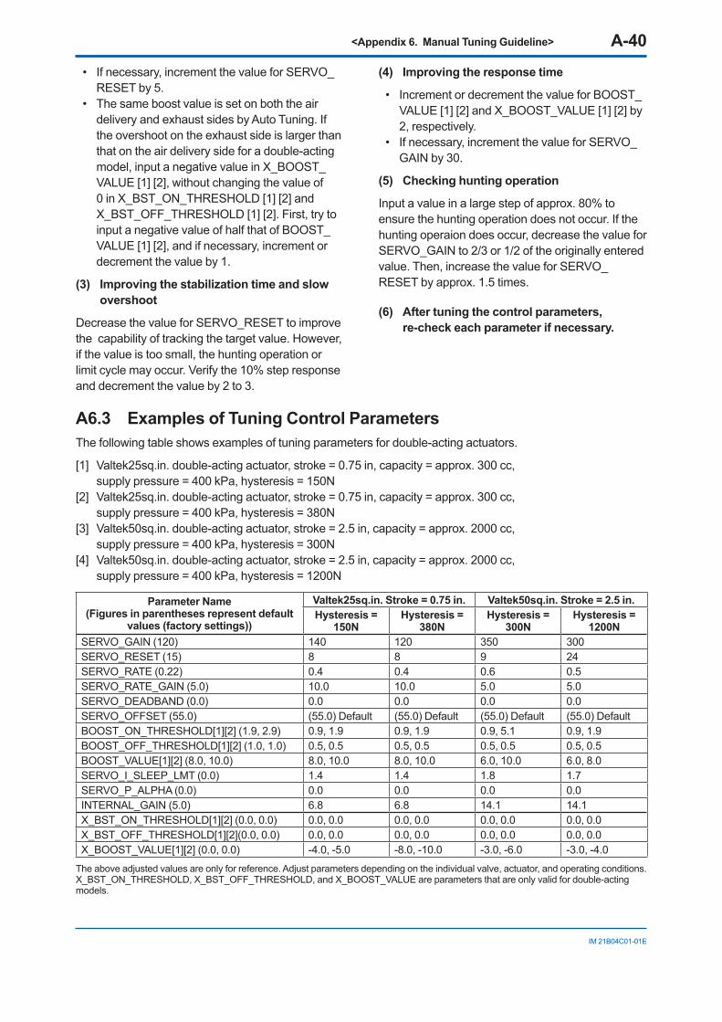
<Appendix 6. Manual Tuning Guideline> A-40
IM 21B04C01-01E
• If necessary, increment the value for SERVO_RESET by 5.
• The same boost value is set on both the air delivery and exhaust sides by Auto Tuning. If the overshoot on the exhaust side is larger than that on the air delivery side for a double-acting model, input a negative value in X_BOOST_VALUE [1] [2], without changing the value of 0 in X_BST_ON_THRESHOLD [1] [2] and X_BST_OFF_THRESHOLD [1] [2]. First, try to input a negative value of half that of BOOST_VALUE [1] [2], and if necessary, increment or decrement the value by 1.
(3) Improving the stabilization time and slow overshoot
Decrease the value for SERVO_RESET to improve the capability of tracking the target value. However, if the value is too small, the hunting operation or limit cycle may occur. Verify the 10% step response and decrement the value by 2 to 3.
(4) Improving the response time
• Increment or decrement the value for BOOST_VALUE [1] [2] and X_BOOST_VALUE [1] [2] by 2, respectively.
• If necessary, increment the value for SERVO_GAIN by 30.
(5) Checking hunting operation
Input a value in a large step of approx. 80% to ensure the hunting operation does not occur. If the hunting operaion does occur, decrease the value for SERVO_GAIN to 2/3 or 1/2 of the originally entered value. Then, increase the value for SERVO_RESET by approx. 1.5 times.
(6) After tuning the control parameters, re-check each parameter if necessary.
A6.3 Examples of Tuning Control ParametersThe following table shows examples of tuning parameters for double-acting actuators.
[1] Valtek25sq.in. double-acting actuator, stroke = 0.75 in, capacity = approx. 300 cc, supply pressure = 400 kPa, hysteresis = 150N
[2] Valtek25sq.in. double-acting actuator, stroke = 0.75 in, capacity = approx. 300 cc, supply pressure = 400 kPa, hysteresis = 380N
[3] Valtek50sq.in. double-acting actuator, stroke = 2.5 in, capacity = approx. 2000 cc, supply pressure = 400 kPa, hysteresis = 300N
[4] Valtek50sq.in. double-acting actuator, stroke = 2.5 in, capacity = approx. 2000 cc, supply pressure = 400 kPa, hysteresis = 1200N
Parameter Name(Figures in parentheses represent default
values (factory settings))
Valtek25sq.in. Stroke = 0.75 in. Valtek50sq.in. Stroke = 2.5 in.Hysteresis =
150NHysteresis =
380NHysteresis =
300NHysteresis =
1200NSERVO_GAIN (120) 140 120 350 300SERVO_RESET (15) 8 8 9 24SERVO_RATE (0.22) 0.4 0.4 0.6 0.5SERVO_RATE_GAIN (5.0) 10.0 10.0 5.0 5.0SERVO_DEADBAND (0.0) 0.0 0.0 0.0 0.0SERVO_OFFSET (55.0) (55.0) Default (55.0) Default (55.0) Default (55.0) DefaultBOOST_ON_THRESHOLD[1][2] (1.9, 2.9) 0.9, 1.9 0.9, 1.9 0.9, 5.1 0.9, 1.9BOOST_OFF_THRESHOLD[1][2] (1.0, 1.0) 0.5, 0.5 0.5, 0.5 0.5, 0.5 0.5, 0.5BOOST_VALUE[1][2] (8.0, 10.0) 8.0, 10.0 8.0, 10.0 6.0, 10.0 6.0, 8.0SERVO_I_SLEEP_LMT (0.0) 1.4 1.4 1.8 1.7SERVO_P_ALPHA (0.0) 0.0 0.0 0.0 0.0INTERNAL_GAIN (5.0) 6.8 6.8 14.1 14.1X_BST_ON_THRESHOLD[1][2] (0.0, 0.0) 0.0, 0.0 0.0, 0.0 0.0, 0.0 0.0, 0.0X_BST_OFF_THRESHOLD[1][2](0.0, 0.0) 0.0, 0.0 0.0, 0.0 0.0, 0.0 0.0, 0.0X_BOOST_VALUE[1][2] (0.0, 0.0) -4.0, -5.0 -8.0, -10.0 -3.0, -6.0 -3.0, -4.0
The above adjusted values are only for reference. Adjust parameters depending on the individual valve, actuator, and operating conditions. X_BST_ON_THRESHOLD, X_BST_OFF_THRESHOLD, and X_BOOST_VALUE are parameters that are only valid for double-acting models.
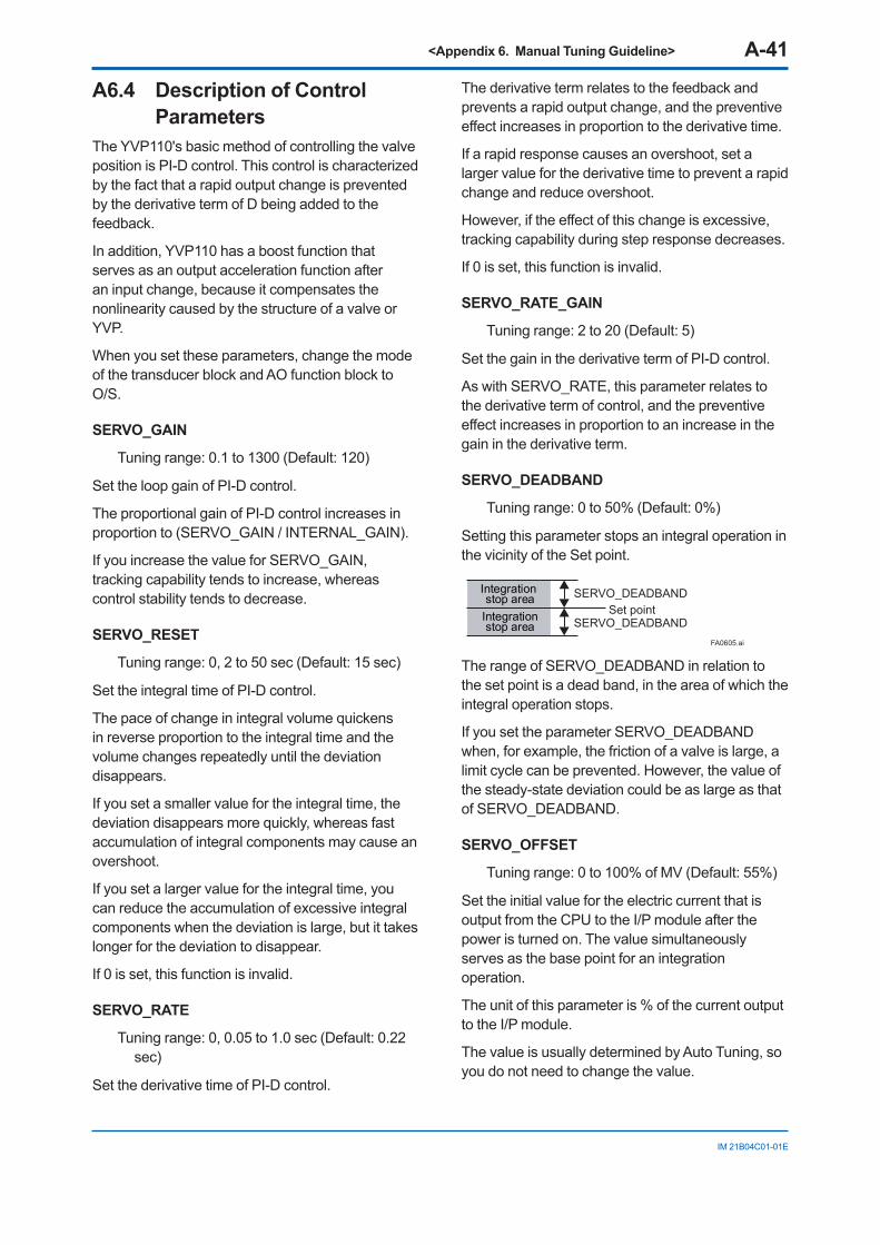
<Appendix 6. Manual Tuning Guideline> A-41
IM 21B04C01-01E
A6.4 Description of Control Parameters
The YVP110's basic method of controlling the valve position is PI-D control. This control is characterized by the fact that a rapid output change is prevented by the derivative term of D being added to the feedback.
In addition, YVP110 has a boost function that serves as an output acceleration function after an input change, because it compensates the nonlinearity caused by the structure of a valve or YVP.
When you set these parameters, change the mode of the transducer block and AO function block to O/S.
SERVO_GAIN
Tuning range: 0.1 to 1300 (Default: 120)
Set the loop gain of PI-D control.
The proportional gain of PI-D control increases in proportion to (SERVO_GAIN / INTERNAL_GAIN).
If you increase the value for SERVO_GAIN, tracking capability tends to increase, whereas control stability tends to decrease.
SERVO_RESET
Tuning range: 0, 2 to 50 sec (Default: 15 sec)
Set the integral time of PI-D control.
The pace of change in integral volume quickens in reverse proportion to the integral time and the volume changes repeatedly until the deviation disappears.
If you set a smaller value for the integral time, the deviation disappears more quickly, whereas fast accumulation of integral components may cause an overshoot.
If you set a larger value for the integral time, you can reduce the accumulation of excessive integral components when the deviation is large, but it takes longer for the deviation to disappear.
If 0 is set, this function is invalid.
SERVO_RATE
Tuning range: 0, 0.05 to 1.0 sec (Default: 0.22 sec)
Set the derivative time of PI-D control.
The derivative term relates to the feedback and prevents a rapid output change, and the preventive effect increases in proportion to the derivative time.
If a rapid response causes an overshoot, set a larger value for the derivative time to prevent a rapid change and reduce overshoot.
However, if the effect of this change is excessive, tracking capability during step response decreases.
If 0 is set, this function is invalid.
SERVO_RATE_GAIN
Tuning range: 2 to 20 (Default: 5)
Set the gain in the derivative term of PI-D control.
As with SERVO_RATE, this parameter relates to the derivative term of control, and the preventive effect increases in proportion to an increase in the gain in the derivative term.
SERVO_DEADBAND
Tuning range: 0 to 50% (Default: 0%)
Setting this parameter stops an integral operation in the vicinity of the Set point.
Integration stop area
Integrationstop area
SERVO_DEADBAND
SERVO_DEADBANDSet point
FA0605.ai
The range of SERVO_DEADBAND in relation to the set point is a dead band, in the area of which the integral operation stops.
If you set the parameter SERVO_DEADBAND when, for example, the friction of a valve is large, a limit cycle can be prevented. However, the value of the steady-state deviation could be as large as that of SERVO_DEADBAND.
SERVO_OFFSET
Tuning range: 0 to 100% of MV (Default: 55%)
Set the initial value for the electric current that is output from the CPU to the I/P module after the power is turned on. The value simultaneously serves as the base point for an integration operation.
The unit of this parameter is % of the current output to the I/P module.
The value is usually determined by Auto Tuning, so you do not need to change the value.
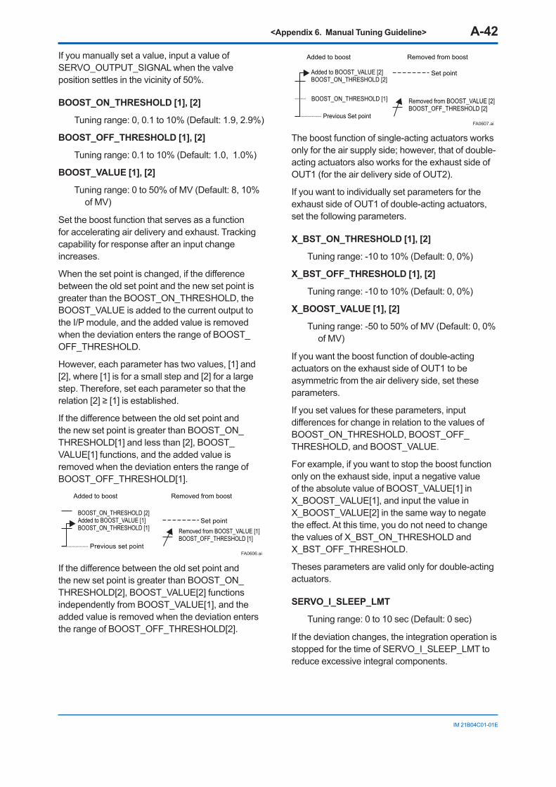
<Appendix 6. Manual Tuning Guideline> A-42
IM 21B04C01-01E
If you manually set a value, input a value of SERVO_OUTPUT_SIGNAL when the valve position settles in the vicinity of 50%.
BOOST_ON_THRESHOLD [1], [2]
Tuning range: 0, 0.1 to 10% (Default: 1.9, 2.9%)
BOOST_OFF_THRESHOLD [1], [2]
Tuning range: 0.1 to 10% (Default: 1.0, 1.0%)
BOOST_VALUE [1], [2]
Tuning range: 0 to 50% of MV (Default: 8, 10% of MV)
Set the boost function that serves as a function for accelerating air delivery and exhaust. Tracking capability for response after an input change increases.
When the set point is changed, if the difference between the old set point and the new set point is greater than the BOOST_ON_THRESHOLD, the BOOST_VALUE is added to the current output to the I/P module, and the added value is removed when the deviation enters the range of BOOST_OFF_THRESHOLD.
However, each parameter has two values, [1] and [2], where [1] is for a small step and [2] for a large step. Therefore, set each parameter so that the relation [2] ≥ [1] is established.
If the difference between the old set point and the new set point is greater than BOOST_ON_THRESHOLD[1] and less than [2], BOOST_VALUE[1] functions, and the added value is removed when the deviation enters the range of BOOST_OFF_THRESHOLD[1].
FA0606.ai
Added to boost
BOOST_ON_THRESHOLD [2]Added to BOOST_VALUE [1]BOOST_ON_THRESHOLD [1]
Previous set point
Set pointRemoved from BOOST_VALUE [1]BOOST_OFF_THRESHOLD [1]
Removed from boost
If the difference between the old set point and the new set point is greater than BOOST_ON_THRESHOLD[2], BOOST_VALUE[2] functions independently from BOOST_VALUE[1], and the added value is removed when the deviation enters the range of BOOST_OFF_THRESHOLD[2].
BOOST_ON_THRESHOLD [1]
FA0607.ai
Added to BOOST_VALUE [2]BOOST_ON_THRESHOLD [2]
Previous Set point
Set point
Removed from BOOST_VALUE [2]BOOST_OFF_THRESHOLD [2]
Added to boost Removed from boost
The boost function of single-acting actuators works only for the air supply side; however, that of double-acting actuators also works for the exhaust side of OUT1 (for the air delivery side of OUT2).
If you want to individually set parameters for the exhaust side of OUT1 of double-acting actuators, set the following parameters.
X_BST_ON_THRESHOLD [1], [2]
Tuning range: -10 to 10% (Default: 0, 0%)
X_BST_OFF_THRESHOLD [1], [2]
Tuning range: -10 to 10% (Default: 0, 0%)
X_BOOST_VALUE [1], [2]
Tuning range: -50 to 50% of MV (Default: 0, 0% of MV)
If you want the boost function of double-acting actuators on the exhaust side of OUT1 to be asymmetric from the air delivery side, set these parameters.
If you set values for these parameters, input differences for change in relation to the values of BOOST_ON_THRESHOLD, BOOST_OFF_THRESHOLD, and BOOST_VALUE.
For example, if you want to stop the boost function only on the exhaust side, input a negative value of the absolute value of BOOST_VALUE[1] in X_BOOST_VALUE[1], and input the value in X_BOOST_VALUE[2] in the same way to negate the effect. At this time, you do not need to change the values of X_BST_ON_THRESHOLD and X_BST_OFF_THRESHOLD.
Theses parameters are valid only for double-acting actuators.
SERVO_I_SLEEP_LMT
Tuning range: 0 to 10 sec (Default: 0 sec)
If the deviation changes, the integration operation is stopped for the time of SERVO_I_SLEEP_LMT to reduce excessive integral components.
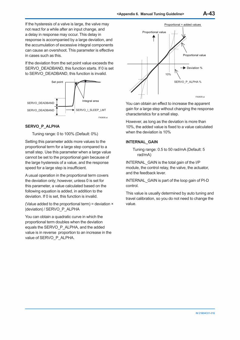
<Appendix 6. Manual Tuning Guideline> A-43
IM 21B04C01-01E
If the hysteresis of a valve is large, the valve may not react for a while after an input change, and a delay in response may occur. This delay in response is accompanied by a large deviation, and the accumulation of excessive integral components can cause an overshoot. This parameter is effective in cases such as this.
If the deviation from the set point value exceeds the SERVO_DEADBAND, this function starts. If 0 is set to SERVO_DEADBAND, this function is invalid.
FA0608.ai
Set point
SERVO_DEADBAND
SERVO_DEADBAND SERVO_I_SLEEP_LMT
Integral area
SERVO_P_ALPHA
Tuning range: 0 to 100% (Default: 0%)
Setting this parameter adds more values to the proportional term for a large step compared to a small step. Use this parameter when a large value cannot be set to the proportional gain because of the large hysteresis of a value, and the response speed for a large step is insufficient.
A usual operation in the proportional term covers the deviation only; however, unless 0 is set for this parameter, a value calculated based on the following equation is added, in addition to the deviation. If 0 is set, this function is invalid.
(Value added to the proportional term) = deviation × |deviation| / SERVO_P_ALPHA
You can obtain a quadratic curve in which the proportional term doubles when the deviation equals the SERVO_P_ALPHA, and the added value is in reverse proportion to an increase in the value of SERVO_P_ALPHA.
FA0609.ai
Proportional value
Proportional + added values
Proportional value
Deviation %
10%
SERVO_P_ALPHA %
You can obtain an effect to increase the apparent gain for a large step without changing the response characteristics for a small step.
However, as long as the deviation is more than 10%, the added value is fixed to a value calculated when the deviation is 10%
INTERNAL_GAIN
Tuning range: 0.5 to 50 rad/mA (Default: 5 rad/mA)
INTERNAL_GAIN is the total gain of the I/P module, the control relay, the valve, the actuator, and the feedback lever.
INTERNAL_GAIN is part of the loop gain of PI-D control.
This value is usually determined by auto tuning and travel calibration, so you do not need to change the value.
<Installation and Operating Precautions for TIIS Flameproof Equipment> 1
EX-B03E
Installation and Operating Precautions for TIIS Flameproof EquipmentApparatus Certified Under Technical Criteria (IEC-compatible Standards)
1. GeneralThe following describes precautions on electrical apparatus of flameproof construction (hereinafter referred to as flameproof apparatus) in explosion-protected apparatus.Following the Labour Safety and Health Laws of Japan, flameproof apparatus is subjected to type tests to meet either the technical criteria for explosionproof electrical machinery and equipment (standards notification no. 556 from the Japanese Ministry of Labour) (hereinafter referred to as technical criteria), in conformity with the IEC Standards, or the “Recommended Practice for Explosion-Protected Electrical Installations in General Industries,” published in 1979. These certified apparatus can be used in hazardous locations where explosive or inflammable gases or vapours may be present.Certified apparatus includes a certification label and an equipment nameplate with the specifications necessary for explosion requirements as well as precautions on explosion protection. Please confirm these precautionary items and use them to meet specification requirements.For electrical wiring and maintenance servicing, please refer to “Internal Wiring Rules” in the Electrical Installation Technical Standards as well as “USER’S GUIDELINES for Electrical Installations for Explosive Gas Atmospheres in General Industry,” published in 1994.To meet flameproof requirements, equipment that can be termed “flameproof” must:(1) Be certified by a Japanese public authority in accordance
with the Labour Safety and Health Laws of Japan and have a certification label in an appropriate location on its case, and
(2) Be used in compliance with the specifications marked on its certification label, equipment nameplate and precautionary information furnished.
2. Electrical Apparatus of Flameproof Type of Explosion-Protected Construction
Electrical apparatus which is of flameproof construction is subjected to a type test and certified by the Japanese Ministry of Labour aiming at preventing explosion caused by electrical apparatus in a factory or any location where inflammable gases or vapours may be present. The flameproof construction is of completely enclosed type and its enclosure shall endure explosive pressures in cases where explosive gases or vapours entering the enclosure cause explosion. In addition, the enclosure construction shall be such that flame caused by explosion does not ignite gases or vapours outside the enclosure.In this manual, the word "flameproof" is applied to the flameproof equipment combined with the types of protection "e", "o", "i", and "d" as well as flameproof equipment.
3. Terminology
(1) EnclosureAn outer shell of an electrical apparatus, which encloses live parts and thus is needed to configure explosion-protected construction.
(2) ShroudA component part which is so designed that the fastening of joint surfaces cannot be loosened unless a special tool is used.
(3) Enclosure internal volumeThis is indicated by:— the total internal volume of the flameproof enclosure minus the volume of the internal components essential to equipment functions.
(4) Path length of joint surfaceOn a joint surface, the length of the shortest path through which flame flows from the inside to outside of the flameproof enclosure. This definition cannot be applied to threaded joints.
(5) Gaps between joint surfacesThe physical distance between two mating surfaces, or differences in diameters if the mating surfaces are cylindrical.
Note: The permissible sizes of gaps between joint surfaces, the path length of a joint surface and the number of joint threads are determined by such factors as the enclosure’s internal volume, joint and mating surface construction, and the explosion classification of the specified gases and vapours.
4. Installation of Flameproof Apparatus
(1) Installation AreaFlameproof apparatus may be installed, in accordance with applicable gases, in a hazardous area in Zone 1 or 2, where the specified gases are present. Those apparatus shall not be installed in a hazardous area in Zone 0.
Note: Hazardous areas are classified in zones based upon the frequency of the appearance and the duration of an explosive gas atmosphere as follows:Zone 0: An area in which an explosive gas atmosphere is present
continuously or is present for long periods.Zone 1: An area in which an explosive gas atmosphere is likely to
occur in normal operation.Zone 2: An area in which an explosive gas atmosphere is not
likely to occur in normal operation and if it does occur it will exist for a short period only.
(2) Environmental ConditionsThe standard environmental condition for the installation of flameproof apparatus is limited to an ambient temperature range from –20°C to +40°C (for products certified under Technical Criteria). However, some field-mounted instruments may be certified at an ambient temperature up to +60°C as indicated on the instrument nameplates. If the flameproof apparatus are exposed to direct sunshine or radiant heat from plant facilities, appropriate thermal protection measures shall be taken.
5. External Wiring for Flameproof ApparatusFlameproof apparatus require cable wiring or flameproof metal conduits for their electrical connections. For cable wiring, cable glands (cable entry devices for flameproof type) to wiring connections shall be attached. For metal conduits, attach sealing fittings as close to wiring connections as possible and completely seal the apparatus. All non-live metal parts such as the enclosure shall be securely grounded.For details, see the “USER’S GUIDELINES for Electrical Installations for Explosive Gas Atmospheres in General Industry,” published in 1994.
(1) Cable Wiring• For cable wiring, cable glands (cable entry devices for
flameproof type) specified or supplied with the apparatus shall be directly attached to the wiring connections to complete sealing of the apparatus.
• Screws that connect cable glands to the apparatus are those for G-type parallel pipe threads (JIS B 0202) with no sealing property. To protect the apparatus from corrosive gases or moisture, apply non-hardening sealant such as liquid gaskets to those threads for waterproofing.
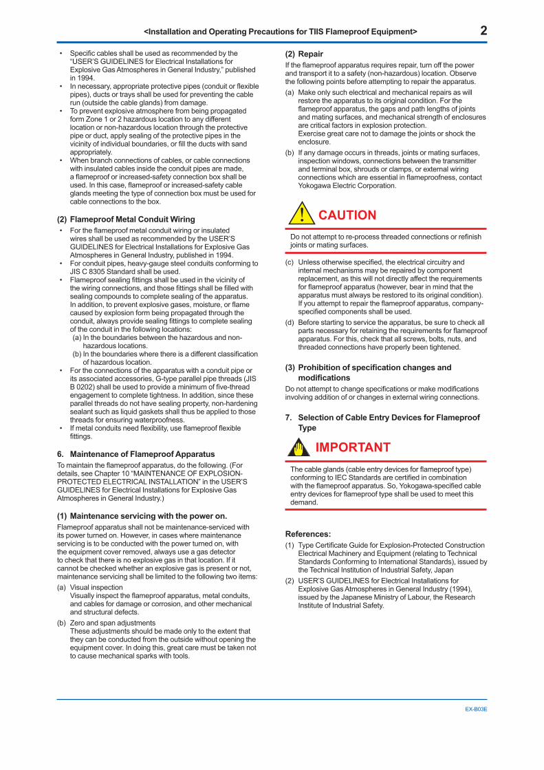
<Installation and Operating Precautions for TIIS Flameproof Equipment> 2
EX-B03E
• Specific cables shall be used as recommended by the “USER’S GUIDELINES for Electrical Installations for Explosive Gas Atmospheres in General Industry,” published in 1994.
• In necessary, appropriate protective pipes (conduit or flexible pipes), ducts or trays shall be used for preventing the cable run (outside the cable glands) from damage.
• To prevent explosive atmosphere from being propagated form Zone 1 or 2 hazardous location to any different location or non-hazardous location through the protective pipe or duct, apply sealing of the protective pipes in the vicinity of individual boundaries, or fill the ducts with sand appropriately.
• When branch connections of cables, or cable connections with insulated cables inside the conduit pipes are made, a flameproof or increased-safety connection box shall be used. In this case, flameproof or increased-safety cable glands meeting the type of connection box must be used for cable connections to the box.
(2) Flameproof Metal Conduit Wiring• For the flameproof metal conduit wiring or insulated
wires shall be used as recommended by the USER’S GUIDELINES for Electrical Installations for Explosive Gas Atmospheres in General Industry, published in 1994.
• For conduit pipes, heavy-gauge steel conduits conforming to JIS C 8305 Standard shall be used.
• Flameproof sealing fittings shall be used in the vicinity of the wiring connections, and those fittings shall be filled with sealing compounds to complete sealing of the apparatus. In addition, to prevent explosive gases, moisture, or flame caused by explosion form being propagated through the conduit, always provide sealing fittings to complete sealing of the conduit in the following locations:(a) In the boundaries between the hazardous and non-
hazardous locations.(b) In the boundaries where there is a different classification
of hazardous location.• For the connections of the apparatus with a conduit pipe or
its associated accessories, G-type parallel pipe threads (JIS B 0202) shall be used to provide a minimum of five-thread engagement to complete tightness. In addition, since these parallel threads do not have sealing property, non-hardening sealant such as liquid gaskets shall thus be applied to those threads for ensuring waterproofness.
• If metal conduits need flexibility, use flameproof flexible fittings.
6. Maintenance of Flameproof ApparatusTo maintain the flameproof apparatus, do the following. (For details, see Chapter 10 “MAINTENANCE OF EXPLOSION-PROTECTED ELECTRICAL INSTALLATION” in the USER’S GUIDELINES for Electrical Installations for Explosive Gas Atmospheres in General Industry.)
(1) Maintenance servicing with the power on.Flameproof apparatus shall not be maintenance-serviced with its power turned on. However, in cases where maintenance servicing is to be conducted with the power turned on, with the equipment cover removed, always use a gas detector to check that there is no explosive gas in that location. If it cannot be checked whether an explosive gas is present or not, maintenance servicing shall be limited to the following two items:(a) Visual inspection
Visually inspect the flameproof apparatus, metal conduits, and cables for damage or corrosion, and other mechanical and structural defects.
(b) Zero and span adjustments These adjustments should be made only to the extent that they can be conducted from the outside without opening the equipment cover. In doing this, great care must be taken not to cause mechanical sparks with tools.
(2) RepairIf the flameproof apparatus requires repair, turn off the power and transport it to a safety (non-hazardous) location. Observe the following points before attempting to repair the apparatus.(a) Make only such electrical and mechanical repairs as will
restore the apparatus to its original condition. For the flameproof apparatus, the gaps and path lengths of joints and mating surfaces, and mechanical strength of enclosures are critical factors in explosion protection. Exercise great care not to damage the joints or shock the enclosure.
(b) If any damage occurs in threads, joints or mating surfaces, inspection windows, connections between the transmitter and terminal box, shrouds or clamps, or external wiring connections which are essential in flameproofness, contact Yokogawa Electric Corporation.
CAUTIONDo not attempt to re-process threaded connections or refinish joints or mating surfaces.
(c) Unless otherwise specified, the electrical circuitry and internal mechanisms may be repaired by component replacement, as this will not directly affect the requirements for flameproof apparatus (however, bear in mind that the apparatus must always be restored to its original condition). If you attempt to repair the flameproof apparatus, company-specified components shall be used.
(d) Before starting to service the apparatus, be sure to check all parts necessary for retaining the requirements for flameproof apparatus. For this, check that all screws, bolts, nuts, and threaded connections have properly been tightened.
(3) Prohibition of specification changes and modifications
Do not attempt to change specifications or make modifications involving addition of or changes in external wiring connections.
7. Selection of Cable Entry Devices for Flameproof Type
IMPORTANTThe cable glands (cable entry devices for flameproof type) conforming to IEC Standards are certified in combination with the flameproof apparatus. So, Yokogawa-specified cable entry devices for flameproof type shall be used to meet this demand.
References:(1) Type Certificate Guide for Explosion-Protected Construction
Electrical Machinery and Equipment (relating to Technical Standards Conforming to International Standards), issued by the Technical Institution of Industrial Safety, Japan
(2) USER’S GUIDELINES for Electrical Installations for Explosive Gas Atmospheres in General Industry (1994), issued by the Japanese Ministry of Labour, the Research Institute of Industrial Safety.
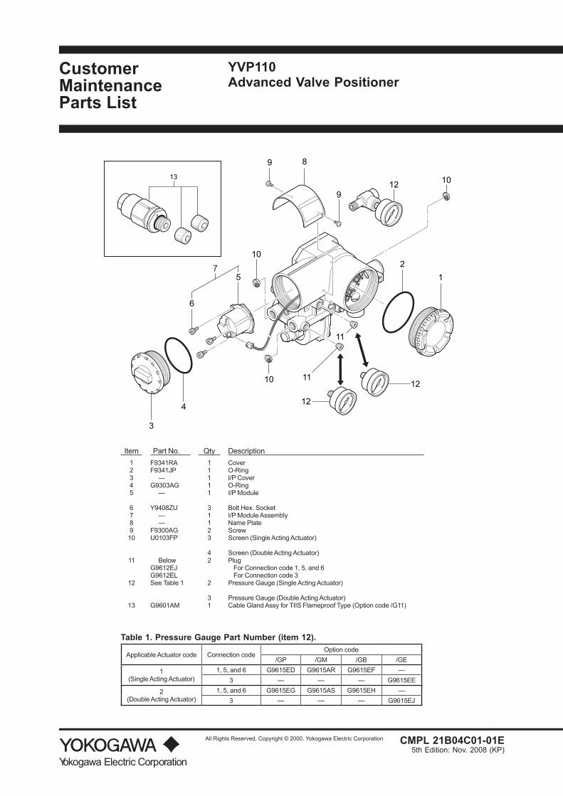
Yokogawa Electric Corporation
All Rights Reserved, Copyright © 2000, Yokogawa Electric Corporation
Customer Maintenance Parts List
3
4
6
5
9 8
9
21
11
1112
12
10
10
101213
7
Item Part No. Qty Description1 F9341RA 1 Cover2 F9341JP 1 O-Ring3 — 1 I/P Cover4 G9303AG 1 O-Ring5 — 1 I/P Module
6 Y9408ZU 3 Bolt Hex. Socket7 — 1 I/P Module Assembly8 — 1 Name Plate9 F9300AG 2 Screw10 U0103FP 3 Screen (Single Acting Actuator)
4 Screen (Double Acting Actuator)11 Below 2 Plug
G9612EJ For Connection code 1, 5, and 6G9612EL For Connection code 3
12 See Table 1 2 Pressure Gauge (Single Acting Actuator)
3 Pressure Gauge (Double Acting Actuator)13 G9601AM 1 Cable Gland Assy for TIIS Flameproof Type (Option code /G11)
Table 1. Pressure Gauge Part Number (item 12).
Applicable Actuator code Connection codeOption code
/GP /GM /GB /GE
1(Single Acting Actuator)
1, 5, and 6 G9615ED G9615AR G9615EF —3 — — — G9615EE
2(Double Acting Actuator)
1, 5, and 6 G9615EG G9615AS G9615EH —3 — — — G9615EJ
YVP110Advanced Valve Positioner
CMPL 21B04C01-01E5th Edition: Nov. 2008 (KP)
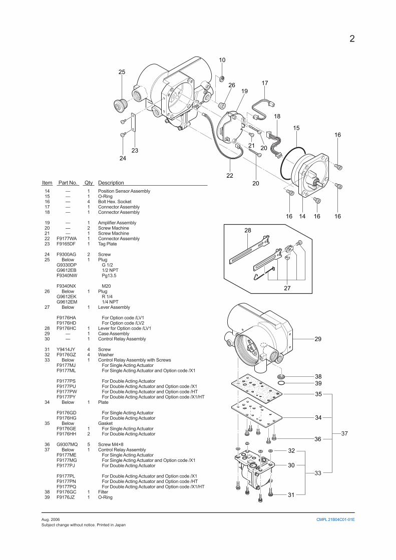
2
CMPL 21B04C01-01E
25
2423
2619
17
10
2220
2021
18
1516
16161416
29
3839
35
30
32
31
34
36
33
37
28
27
Item Part No. Qty Description14 — 1 Position Sensor Assembly15 — 1 O-Ring16 — 4 Bolt Hex. Socket17 — 1 Connector Assembly18 — 1 Connector Assembly
19 — 1 Amplifier Assembly20 — 2 Screw Machine21 — 1 Screw Machine22 F9177WA 1 Connector Assembly23 F9165DF 1 Tag Plate
24 F9300AG 2 Screw25 Below 1 Plug
G9330DP G 1/2G9612EB 1/2 NPTF9340NW Pg13.5
F9340NX M2026 Below 1 Plug
G9612EK R 1/4G9612EM 1/4 NPT
27 Below 1 Lever Assembly
F9176HA For Option code /LV1F9176HD For Option code /LV2
28 F9176HC 1 Lever for Option code /LV129 — 1 Case Assembly30 — 1 Control Relay Assembly
31 Y9414JY 4 Screw32 F9176GZ 4 Washer33 Below 1 Control Relay Assembly with Screws
F9177MJ For Single Acting ActuatorF9177ML For Single Acting Actuator and Option code /X1
F9177PS For Double Acting ActuatorF9177PU For Double Acting Actuator and Option code /X1F9177PW For Double Acting Actuator and Option code /HTF9177PY For Double Acting Actuator and Option code /X1/HT
34 Below 1 Plate
F9176GD For Single Acting ActuatorF9176HG For Double Acting Actuator
35 Below GasketF9176GE 1 For Single Acting ActuatorF9176HH 2 For Double Acting Actuator
36 G9307MQ 5 Screw M4×837 Below 1 Control Relay Assembly
F9177ME For Single Acting ActuatorF9177MG For Single Acting Actuator and Option code /X1F9177PJ For Double Acting Actuator
F9177PL For Double Acting Actuator and Option code /X1F9177PN For Double Acting Actuator and Option code /HTF9177PQ For Double Acting Actuator and Option code /X1/HT
38 F9176GC 1 Filter39 F9176JZ 1 O-Ring
Aug. 2006Subject change without notice. Printed in Japan
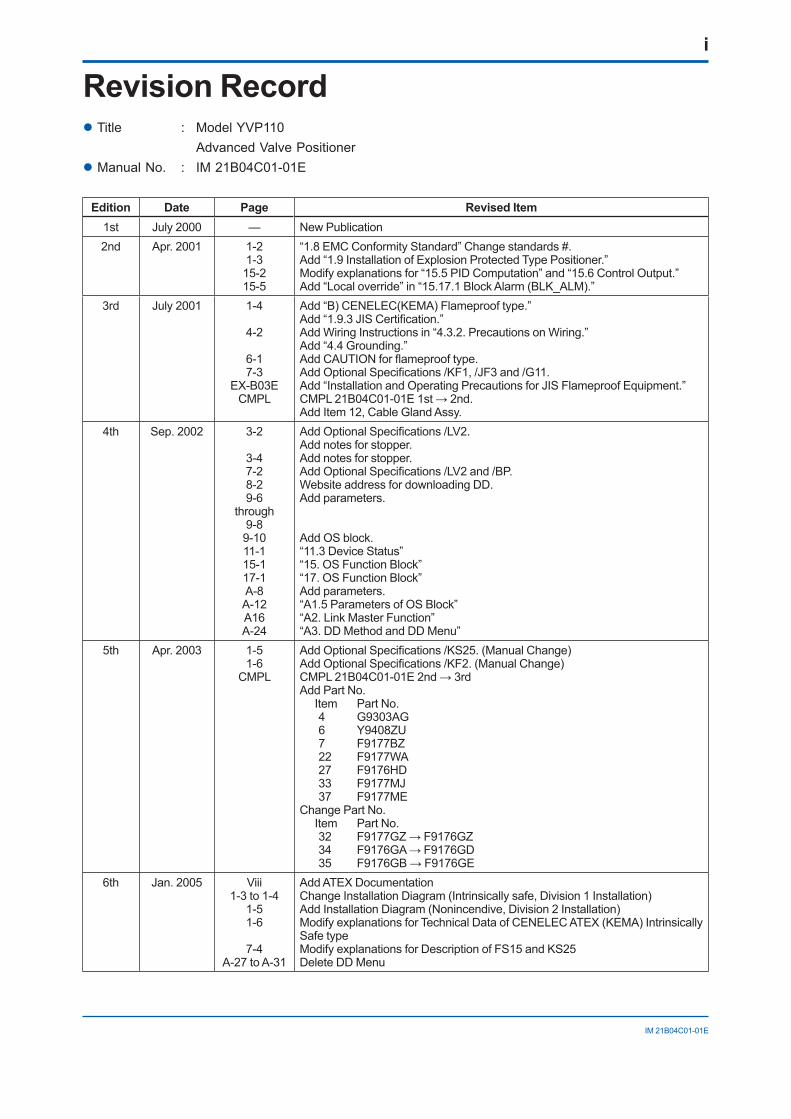
i
IM 21B04C01-01E
Revision Recordl Title : Model YVP110 Advanced Valve Positionerl Manual No. : IM 21B04C01-01E
Edition Date Page Revised Item1st July 2000 — New Publication2nd Apr. 2001 1-2
1-315-215-5
“1.8 EMC Conformity Standard” Change standards #.Add “1.9 Installation of Explosion Protected Type Positioner.”Modify explanations for “15.5 PID Computation” and “15.6 Control Output.”Add “Local override” in “15.17.1 Block Alarm (BLK_ALM).”
3rd July 2001 1-4
4-2
6-17-3
EX-B03ECMPL
Add “B) CENELEC(KEMA) Flameproof type.”Add “1.9.3 JIS Certification.”Add Wiring Instructions in “4.3.2. Precautions on Wiring.”Add “4.4 Grounding.”Add CAUTION for flameproof type.Add Optional Specifications /KF1, /JF3 and /G11.Add “Installation and Operating Precautions for JIS Flameproof Equipment.”CMPL 21B04C01-01E 1st → 2nd.Add Item 12, Cable Gland Assy.
4th Sep. 2002 3-2
3-47-28-29-6
through9-89-1011-115-117-1A-8A-12A16A-24
Add Optional Specifications /LV2.Add notes for stopper.Add notes for stopper.Add Optional Specifications /LV2 and /BP.Website address for downloading DD.Add parameters.
Add OS block.“11.3 Device Status”“15. OS Function Block”“17. OS Function Block”Add parameters.“A1.5 Parameters of OS Block”“A2. Link Master Function”“A3. DD Method and DD Menu”
5th Apr. 2003 1-51-6
CMPL
Add Optional Specifications /KS25. (Manual Change)Add Optional Specifications /KF2. (Manual Change)CMPL 21B04C01-01E 2nd → 3rdAdd Part No.
Item Part No.4 G9303AG6 Y9408ZU7 F9177BZ22 F9177WA27 F9176HD33 F9177MJ37 F9177ME
Change Part No.Item Part No.32 F9177GZ → F9176GZ34 F9176GA → F9176GD35 F9176GB → F9176GE
6th Jan. 2005 Viii1-3 to 1-4
1-51-6
7-4A-27 to A-31
Add ATEX DocumentationChange Installation Diagram (Intrinsically safe, Division 1 Installation)Add Installation Diagram (Nonincendive, Division 2 Installation)Modify explanations for Technical Data of CENELEC ATEX (KEMA) Intrinsically Safe typeModify explanations for Description of FS15 and KS25Delete DD Menu
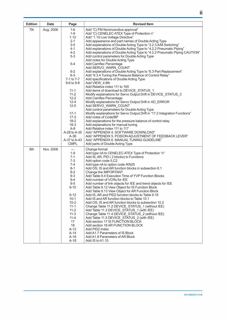
ii
IM 21B04C01-01E
Edition Date Page Revised Item7th Aug. 2006 1-6
1-91-122-13-54-14-25-3
5-4
6-26-3
7-1 to 7-79-6 to 9-8
11-111-212-212-412-5
17-117-318-218-3A-8
A-28 to A-35A-36
A-37 to A-43CMPL
Add “C) FM Nonincendive approval”Add “C) CENELEC ATEX Type of Protection n”Add “1.10 Low Voltage Directive”Add appearance and part names of Double Acting TypeAdd explanations of Double Acting Type to “3.2.3 A/M Switching”Add explanations of Double Acting Type to “4.2.2 Pneumatic Piping”Add explanations of Double Acting Type to “4.2.2 Pneumatic Piping CAUTION”Add control parameters for Double Acting TypeAdd notes for Double Acting TypeAdd Camflex PercentageAdd SERVO_WARN_COUNTAdd explanations of Double Acting Type to “6.3 Part Replacement”Add “6.3.4 Tuning the Pressure Balance of Control Relay”Add specifications of Double Acting TypeAdd VIEW_4 8thAdd Relative index 111 to 165Add items of download to DEVICE_STATUS_1Modify explanations for Servo Output Drift in DEVICE_STATUS_3Add Camflex PercentageModify explanations for Servo Output Drift in XD_ERRORAdd SERVO_WARN_COUNTAdd control parameters for Double Acting TypeModify explanations for Servo Output Drift in “17.2 Integration Functions”Add notes of Code/BPAdd explanations for the pressure balance of control relayAdd explanations for manual tuningAdd Relative index 111 to 117Add “APPENDIX 4. SOFTWARE DOWNLOAD”Add “APPENDIX 5. POSION ADJUSTMENT OF FEEDBACK LEVER”Add “APPENDIX 6. MANUAL TUNING GUIDELINE”Add parts of Double Acting Type
8th Nov. 2008 —1-97-17-37-48-18-29-39-49-59-10
9-1210-110-211-111-211-311-41718
A-12A-14A-16A-18
Change formatAdd type nA to CENELEC ATEX Type of Protection “n”Add IS, AR, PID ( 2 blocks) to FunctionsAdd option code /LC2Add type nA to option code /KN25Add OS, IS and AR function blocks in subsection 8.1Change the IMPORTANTAdd Table 9.4 Execution Time of YVP Function BlocksAdd number of VCRs for /EEAdd number of link objects for /EE and trend objects for /EEAdd Table 9.12 View Object for IS Function BlockAdd Table 9.13 View Object for AR Function BlockAdd IS, AR and PID2 function blocks to Table 9.16Add IS and AR function blocks to Table 10.1Add OS, IS and AR function blocks to subsection 10.2Change Table 11.2 DEVICE_STATUS_1 (without /EE)Add Table 11.3 DEVICE_STATUS_1 (with /EE)Change Table 11.4 DEVICE_STATUS_2 (without /EE)Add Table 11.5 DEVICE_STATUS_2 (with /EE)Add section 17 IS FUNCTION BLOCKAdd section 18 AR FUNCTION BLOCKAdd PID2 IndexAdd A1.7 Parameters of IS BlockAdd A1.8 Parameters of AR BlockAdd IS to A1.10
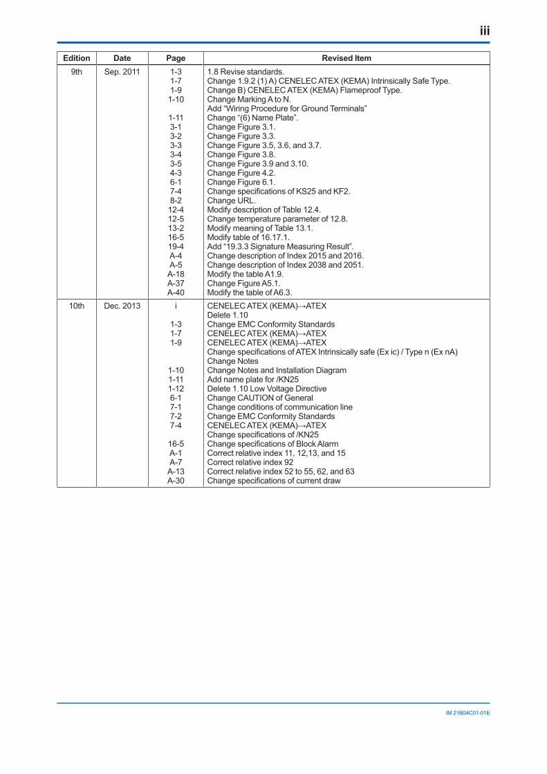
iii
IM 21B04C01-01E
Edition Date Page Revised Item9th Sep. 2011 1-3
1-71-91-10
1-113-13-23-33-43-54-36-17-48-212-412-513-216-519-4A-4A-5A-18A-37A-40
1.8 Revise standards.Change 1.9.2 (1) A) CENELEC ATEX (KEMA) Intrinsically Safe Type.Change B) CENELEC ATEX (KEMA) Flameproof Type.Change Marking A to N.Add “Wiring Procedure for Ground Terminals”Change “(6) Name Plate”.Change Figure 3.1.Change Figure 3.3.Change Figure 3.5, 3.6, and 3.7.Change Figure 3.8.Change Figure 3.9 and 3.10.Change Figure 4.2.Change Figure 6.1.Change specifications of KS25 and KF2.Change URL.Modify description of Table 12.4. Change temperature parameter of 12.8.Modify meaning of Table 13.1.Modify table of 16.17.1.Add “19.3.3 Signature Measuring Result”.Change description of Index 2015 and 2016.Change description of Index 2038 and 2051.Modify the table A1.9.Change Figure A5.1.Modify the table of A6.3.
10th Dec. 2013 i
1-31-71-9
1-101-111-126-17-17-27-4
16-5A-1A-7A-13A-30
CENELEC ATEX (KEMA)→ATEXDelete 1.10Change EMC Conformity StandardsCENELEC ATEX (KEMA)→ATEXCENELEC ATEX (KEMA)→ATEXChange specifications of ATEX Intrinsically safe (Ex ic) / Type n (Ex nA)Change NotesChange Notes and Installation DiagramAdd name plate for /KN25Delete 1.10 Low Voltage DirectiveChange CAUTION of GeneralChange conditions of communication lineChange EMC Conformity StandardsCENELEC ATEX (KEMA)→ATEXChange specifications of /KN25Change specifications of Block AlarmCorrect relative index 11, 12,13, and 15Correct relative index 92Correct relative index 52 to 55, 62, and 63Change specifications of current draw