
User's Manual YTA Series Temperature Transmitters...
48
User's Manual Yokogawa Electric Corporation YTA Series Temperature Transmitters (Hardware) [Style: S3] IM 01C50B01-01E IM 01C50B01-01E 12th Edition
Transcript of User's Manual YTA Series Temperature Transmitters...
User'sManual
Yokogawa Electric Corporation
YTA SeriesTemperature Transmitters(Hardware)[Style: S3]
IM 01C50B01-01E
IM 01C50B01-01E12th Edition

i
CONTENTS
IM 01C50B01-01EFD No. IM 01C50B01-01E12th Edition: Nov. 2007(KP)All Rights Reserved, Copyright © 1998, Yokogawa Electric Corporation
CONTENTS
1. PREFACE ...................................................................................................... 1-1
Notes on the User’s Manual .......................................................................... 1-1Notes on Safety and Modifications ................................................................ 1-1For Safe Use of Product ................................................................................ 1-1Warranty ........................................................................................................ 1-2Trademarks .................................................................................................... 1-2ATEX Documentation .................................................................................... 1-3
2. NOTES ON HANDLING ................................................................................ 2-1
2.1 Nameplate ........................................................................................... 2-12.2 Transport ............................................................................................. 2-12.3 Storage ................................................................................................ 2-12.4 Choosing the Installation Location ...................................................... 2-12.5 Use of a Transceiver ........................................................................... 2-22.6 Insulation Resistance Test and Withstand Voltage Test .................... 2-2
2.6.1 Insulation resistance test procedure ............................................ 2-22.6.2 Withstand voltage test procedure ................................................ 2-3
2.7 Installation of Explosion Protected Type Transmitters ....................... 2-32.7.1 CSA Certification .......................................................................... 2-32.7.2 CENELEC ATEX (KEMA) Certification ........................................ 2-52.7.3 FM Certification ............................................................................ 2-82.7.4 TIIS Certification ........................................................................... 2-92.7.5 SAA Certification ........................................................................ 2-102.7.6 IECEx Certification ..................................................................... 2-11
2.8 EMC Conformity Standards .............................................................. 2-112.9 Low Voltage Directive ....................................................................... 2-11
3. PART NAMES AND FUNCTIONS ................................................................ 3-1
3.1 Part Names ......................................................................................... 3-13.2 Setting the Hardware Error Burnout Change-over Switch ................. 3-23.3 Built-in Indicator Display Function ...................................................... 3-2
4. INSTALLATION ............................................................................................. 4-1
5. WIRING .......................................................................................................... 5-1
5.1 Notes on Wiring .................................................................................. 5-15.2 Loop Construction ............................................................................... 5-15.3 Cable Selection ................................................................................... 5-2
5.3.1 Input signal Cable Selection ........................................................ 5-25.3.2 Output Signal Cable Selection ..................................................... 5-2
5.4 Cable and Terminal Connections ....................................................... 5-25.4.1 Input Terminal Connections ......................................................... 5-25.4.2 Output Terminal Connection ........................................................ 5-3
5.5 Wiring Cautions ................................................................................... 5-45.6 Grounding ............................................................................................ 5-5
ii
CONTENTS
IM 01C50B01-01E
6. MAINTENANCE............................................................................................. 6-1
6.1 General ................................................................................................ 6-16.2 Calibration ........................................................................................... 6-1
6.2.1 Selection of Equipment for Calibration ........................................ 6-16.2.2 Calibration Procedure ................................................................... 6-1
6.3 Disassembly and Assembly ................................................................ 6-26.3.1 Replacement of Built-in Indicator ................................................. 6-36.3.2 Replacement of CPU Assembly ................................................... 6-3
6.4 Troubleshooting ................................................................................... 6-46.4.1 Basic Troubleshooting Flow ......................................................... 6-46.4.2 Example of Troubleshooting Flow................................................ 6-4
6.5 Integral Indicator and Error Display .................................................... 6-6
7. GENERAL SPECIFICATIONS ...................................................................... 7-1
7.1 Standard Specifications ...................................................................... 7-17.2 Model and Suffix Codes ...................................................................... 7-57.3 Optional Specifications ........................................................................ 7-57.4 Dimensions .......................................................................................... 7-8
INSTALLATION AND OPERATING PRECAUTIONS FOR JIS FLAMEPROOFEQUIPMENT ........................................................................................ EX-B03E
Customer Maintenance Parts List ..................................... CMPL 01C50B01-02E
REVISION RECORD
IM 01C50B01-01E1-1
1. PREFACE
1. PREFACEThe YTA temperature transmitter is fully factory-testedaccording to the specifications indicated on the order.
In order for the YTA temperature transmitter to befully functional and to operate in an efficient manner,the manual must be carefully read to become familiarwith the functions, operation, and handling of theYTA.
This manual gives instructions on handling, wiring andmaintenance of YTA110, YTA310 and YTA320temperature transmitters. Changing the parametersettings requires a terminal dedicated to the HARTprotocol or the BRAIN protocol. For details on how toset the parameters of these transmitters, refer to the“BRAIN Protocol” IM 0lC50T03-01E or “HARTProtocol” IM 01C50T01-01E.
For FOUNDATION Fieldbus communication type,please refer to IM 01C50T02-01E in addition to thismanual.
Notes on the User’s Manual • This manual should be delivered to the end user. • The information contained in this manual is subject
to change without prior notice. • The information contained in this manual, in whole
or part, shall not be transcribed or copied withoutnotice.
• In no case does this manual guarantee the merchantability of the transmitter or its adaptability to aspecific client need.
• Should any doubt or error be found in this manual,submit inquiries to your local dealer.
• No special specifications are contained in thismanual.
• Changes to specifications, structure, and componentsused may not lead to the revision of this manualunless such changes affect the function and perfor-mance of the transmitter.
Notes on Safety and Modifications • Before handling the YTA, it is absolutely imperative
that users of this equipment read and observe thesafety instructions mentioned in each section of themanual in order to ensure the protection and safetyof operators, the YTA itself and the system contain-ing the transmitter. We are not liable for anyaccidents arising out of handling that does notadhere to the guidelines established in the safetyinstructions.
• No maintenance should be performed on explosion-proof type temperature transmitters while theequipment is energized. If maintenance is requiredwith the cover open, always first use a gas detectorto check that no explosive gases are present.
• If the user attempts to repair or modify anexplosionproof type transmitter and is unable torestore it to its original condition, damage to theexplosionproof features result, leading to dangerousconditions. Contact your authorized YokogawaElectric Corporation representative for repairs ormodifications of an explosionproof type transmitter.
For Safe Use of ProductPlease give your attention to the followings.
(a) Installation• The instrument must be installed by an expert
engineer or a skilled personnel. The proceduresdescribed about INSTALLATION are not permittedfor operators.
• In case of high process temperature, care should betaken not to burn yourself because the surface of thecase reaches a high temperature.
• All installation shall comply with local installationrequirement and local electrical code.
(b) Wiring• The instrument must be installed by an expert
engineer or a skilled personnel. The proceduresdescribed about WIRING are not permitted foroperators.
• Please confirm that voltages between the powersupply and the instrument before connecting thepower cables and that the cables are not poweredbefore connecting.
(c) Maintenance• Please do not carry out except being written to a
maintenance descriptions. When these proceduresare needed, please contact nearest YOKOGAWAoffice.
• Care should be taken to prevent the build up of drift,dust or other material on the display glass andname plate. In case of its maintenance, soft and drycloth is used.

IM 01C50B01-01E1-2
1. PREFACE
(d) Modification• Yokogawa will not be liable for malfunctions or
damage resulting from any modification made to thisinstrument by the customer.
Symbols used in this manualThe YTA temperature transmitter and this manual usethe following safety related symbols and signals.
WARNING
Contains precautions to protect against thechance of explosion or electric shock which, ifnot observed, could lead to death or seriousinjury.
CAUTION
Contains precautions to protect against danger,which, if not observed, could lead to personalinjury or damage to the instrument.
IMPORTANT
Contains precautions to be observed to protectagainst adverse conditions that may lead todamage to the instrument or a system failure.
NOTE
Contains precautions to be observed with regardto understanding operation and functions.
Some of the diagrams in this manual are partiallyomitted, described in writing, or simplified for ease ofexplanation. The screen drawings contained in theinstruction manual may have a display position orcharacters (upper/lower case) that differ slightly fromthe full-scale screen to an extent that does not hinderthe understanding of functions or monitoring ofoperation.
Warranty • The warranty period of the instrument is written on
the estimate sheet that is included with your pur-chase. Any trouble arising during the warrantyperiod shall be repaired free of charge.
• Inquiries with regard to problems with the instru-ment shall be accepted by the sales outlet or ourlocal dealer representative.
• Should the instrument be found to be defective,inform us of the model name and the serial numberof the instrument together with a detailed descriptionof nonconformance and a progress report. Outlinedrawings or related data will also be helpful forrepair.
• Whether or not the defective instrument is repairedfree of charge depends on the result of our inspec-tion.
Conditions not eligible for charge-exemptrepair.
• Problems caused by improper or insufficientmaintenance on the part of the customer.
• Trouble or damage caused by mishandling, misus-age, or storage that exceeds the design or specifica-tion requirements.
• Problems caused by improper installation location orby maintenance conducted in a non-conforminglocation.
• Trouble or damage was caused by modification orrepair that was handled by a party or parties otherthan our consigned agent.
• Trouble or damage was caused by inappropriaterelocation following delivery.
• Trouble or damage was caused by fire, earthquake,wind or flood damage, lightning strikes or other actsof God that are not directly a result of problems withthis instrument.
Trademarks • HART is a trademark of the HART Communication
Foundation. • Registered trademarks or trademarks appearing in
this manual are not designated by a TM or ®symbol.
• Other company names and product names used inthis manual are the registered trademarks or trade-marks of their respective owners.

IM 01C50B01-01E1-3
1. PREFACE
ATEX DocumentationThis procedure is only applicable to the countries inEuropean Union.
GB
All instruction manuals for ATEX Ex related productsare available in English, German and French. Shouldyou require Ex related instructions in your locallanguage, you are to contact your nearest Yokogawaoffice or representative.
DK
Alle brugervejledninger for produkter relateret tilATEX Ex er tilgængelige på engelsk, tysk og fransk.Skulle De ønske yderligere oplysninger om håndteringaf Ex produkter på eget sprog, kan De rettehenvendelse herom til den nærmeste Yokogawaafdeling eller forhandler.
I
Tutti i manuali operativi di prodotti ATEXcontrassegnati con Ex sono disponibili in inglese,tedesco e francese. Se si desidera ricevere i manualioperativi di prodotti Ex in lingua locale, mettersi incontatto con l’ufficio Yokogawa più vicino o con unrappresentante.
E
Todos los manuales de instrucciones para los productosantiexplosivos de ATEX están disponibles en inglés,alemán y francés. Si desea solicitar las instrucciones deestos artículos antiexplosivos en su idioma local,deberá ponerse en contacto con la oficina o elrepresentante de Yokogawa más cercano.
NL
Alle handleidingen voor producten die te makenhebben met ATEX explosiebeveiliging (Ex) zijnverkrijgbaar in het Engels, Duits en Frans. Neem,indien u aanwijzingen op het gebied vanexplosiebeveiliging nodig hebt in uw eigen taal, contactop met de dichtstbijzijnde vestiging van Yokogawa ofmet een vertegenwoordiger.
SF
Kaikkien ATEX Ex -tyyppisten tuotteiden käyttöhjeetovat saatavilla englannin-, saksan- ja ranskankielisinä.Mikäli tarvitsette Ex -tyyppisten tuotteiden ohjeitaomalla paikallisella kielellännne, ottakaa yhteyttälähimpään Yokogawa-toimistoon tai -edustajaan.
P
Todos os manuais de instruções referentes aos produtosEx da ATEX estão disponíveis em Inglês, Alemão eFrancês. Se necessitar de instruções na sua línguarelacionadas com produtos Ex, deverá entrar emcontacto com a delegação mais próxima ou com umrepresentante da Yokogawa.
F
Tous les manuels d’instruction des produits ATEX Exsont disponibles en langue anglaise, allemande etfrançaise. Si vous nécessitez des instructions relativesaux produits Ex dans votre langue, veuillez biencontacter votre représentant Yokogawa le plus proche.
D
Alle Betriebsanleitungen für ATEX Ex bezogeneProdukte stehen in den Sprachen Englisch, Deutschund Französisch zur Verfügung. Sollten Sie dieBetriebsanleitungen für Ex-Produkte in IhrerLandessprache benötigen, setzen Sie sich bitte mitIhrem örtlichen Yokogawa-Vertreter in Verbindung.
S
Alla instruktionsböcker för ATEX Ex (explosionssäkra)produkter är tillgängliga på engelska, tyska ochfranska. Om Ni behöver instruktioner för dessaexplosionssäkra produkter på annat språk, skall Nikontakta närmaste Yokogawakontor eller representant.
GR
ATEX Ex , . Ex
Yokogawa .
IM 01C50B01-01E1-4
1. PREFACE
LT
LV
PL
EST
SLO
H
BG
RO
M
CZ
SK

IM 01C50B01-01E2-1
2. NOTES ON HANDLING
2. NOTES ON HANDLING
The YTA temperature transmitter is fully factory-tested upon shipment. When the YTA is delivered,check the appearance for damage, and also check thatthe transmitter mounting parts shown in Figure 2.1 areincluded with your shipment. If “No MountingBracket” is indicated, no transmitter mounting bracketis included.
U-bolt nut
U-bolt nut
Horizontalpipe mountingbracketVertical pipe
mountingbracket
Transmitterfastening bolt
Springwasher
Springwasher
U-bolt
F0201.EPS
Bracketfastening bolt
Bracketfastening nut
Figure 2.1 Transmitter mounting parts
2.1 NameplateThe model name and configuration are indicated onthe nameplate. Verify that the configuration indicatedin the “Model and Suffix Code” in Chapter 7 is incompliance with the specifications written on the ordersheet.
Factory-shipped range and unit
TEMPERATURETRANSMITTER
YTA
F0202.EPS
Model nameSerial No.
Style code
Specification code
TOKYO 180-8750 JAPAN
420 mA DC
10.530 (42) V DC:Refer to USER’S MANUAL.
Figure 2.2 Name plate
2.2 TransportTo prevent damage while in transit, leave the transmit-ter in the original shipping container until it reachesthe installation site.
2.3 StorageWhen an extended storage period is expected, observethe following precautions:1. If at all possible, store the transmitter in factory-
shipped condition, that is, in the original shippingcontainer.
2. Choose a storage location that satisfies the follow-ing requirements.
• A location that is not exposed to rain or water. • A location subject to a minimum of vibration or
impact. • The following temperature and humidity range is
recommended. Ordinary temperature and humidity(25°C, 65%) are preferable.
Temperature: No Integral indicator –40 to 85°CWith Integral indicator –30 to 80°C
Humidity: 5 to 100% RH (at 40°C)
3. The performance of the transmitter may be im-paired if stored in an area exposed to direct rain andwater. To avoid damage to the transmitter, install itimmediately after removal from shipping container.Follow wiring instructions in Chapter 5.
2.4 Choosing the InstallationLocation
Although the temperature transmitter is designed tooperate in a vigorous environment, to maintainstability and accuracy, the following is recommended:
(1) Ambient TemperatureIt is preferable to not to expose the instrument toextreme temperatures or temperature fluctuations. Ifthe instrument is exposed to radiation heat a thermalprotection system and appropriate ventilation isrecommended.
(2) Environmental RequirementsDo not allow the instrument to be installed in alocation that is exposed to corrosive atmosphericconditions. When using the instrument in a corrosiveenvironment, ensure the location is well ventilated.The unit and its wiring should be protected fromexposure to rainwater.

IM 01C50B01-01E2-2
2. NOTES ON HANDLING
(3) Impact and VibrationIt is recommended that the instrument be installed in alocation that is subject to a minimum amount of impactand vibration.
2.5 Use of a TransceiverAlthough the temperature transmitter is designed toresist influence from high frequency noise; use of atransceiver in the vicinity of installation may causeproblems. Installing the transmitter in an area free fromhigh frequency noise (RFI) is recommended.
2.6 Insulation Resistance Testand Withstand Voltage Test
CAUTION
(1) Overvoltage of the test voltage that is sosmall that it does not cause an dielectricbreakdown may in fact deteriorate insulationand lower the safety performance; to preventthis it is recommended that the amount oftesting be kept to a minimum.
(2) The voltage for the insulation resistance testmust be 500 VAC or lower, and the voltagefor the withstand voltage test must be 500VAC or lower. Failure to heed these guide-lines may cause faulty operation.
(3) Where a built-in arrester is provided (suffixcode: /A), the voltage for the insulationresistance test must be 100 VDC or lower,and the voltage for the withstand voltage testmust be 100 VAC or lower. Failure to heedthese guidelines may cause faulty operation.
Follow the steps below to perform the test, the wiringof the transmission line must be removed beforeinitiating testing.
2.6.1 Insulation resistance test procedure
Testing between the output terminal andinput terminal
1. Lay transition wiring between the + terminal, the -terminal, and the check terminal of the terminal box.
2. Lay wiring across terminals 1, 2, 3, and 4 of theterminal box.
3. Connect the insulation resistance meter (with thepower turned OFF) between the transition wiring ofSteps 1 and 2 above. The polarity of the inputterminals must be positive and that of the outputterminals must be negative.
4. Turn the power of the insulation resistance meterON and measure the insulation resistance. Theduration of the applied voltage must be the periodduring which 100M or more is confirmed (or20M if the unit is equipped with a built-inarrester).
5. Upon completion of the test, remove the insulationresistance meter, connect a 100K resistor betweenthe transition wiring, and allow the electricity todischarge. Do not touch the terminal with your barehands while the electricity is discharging for morethan 1 second.
Testing between the output terminal andgrounding terminal
1. Lay transition wiring between the + terminal, the -terminal, and the check terminal of the terminal box,then connect an insulation resistance meter (with thepower turned OFF) between the transition wiringand the grounding terminal. The polarity of thetransition wiring must be positive and that of thegrounding terminal must be negative.
2. Turn the power of the insulation resistance meterON and measure the insulation resistance. Theduration of the applied voltage must be the periodduring which 100M or more is confirmed (or20M if the unit is equipped with a built-inarrester).
3. Upon completion of the test, remove the insulationresistance meter, connect a 100K resistor betweenthe transition wiring and the grounding terminal, andallow the electricity to discharge. Do not touch theterminal with your bare hands while the electricity isdischarging for more than 1 second.
Testing between the input terminal andgrounding terminal
1. Lay transition wiring between terminals 1, 2, 3, 4and 5 of the terminal box, and connect the insulationresistor (with the power turned OFF) between thetransition wiring and the grounding terminal. Thepolarity of the transition wiring must be positive andthat of the grounding terminal must be negative.
2. Turn the power of the insulation resistance meterON and measure the insulation resistance. Theduration of the applied voltage must be the periodduring which 100M or more is confirmed (or20M if the unit is equipped with a built-inarrester).
3. Upon completion of the test, remove the insulationresistance meter, connect a 100K resistor betweenthe transition wiring and the grounding terminal, andallow the electricity to discharge. Do not touch theterminal with your bare hands while the electricity isdischarging for more than 1 second.

IM 01C50B01-01E2-3
2. NOTES ON HANDLING
2.6.2 Withstand voltage test procedure
Testing between the output terminal and theinput terminal
1. Lay transition wiring between the + terminal, the –terminal, and the check terminal of the terminal box.
2. Lay transition wiring between terminals 1, 2, 3, 4and 5 of the terminal box.
3. Connect the withstand voltage tester (with the powerturned OFF) between the transition wiring shown inSteps 1 and 2 above.
4. After setting the current limit value of the withstandvoltage tester to 10mA, turn the power ON, andcarefully increase the impressed voltage from 0V tothe specified value.
5. The voltage at the specified value must remain for aduration of one minute.
6. Upon completion of the test, carefully reduce thevoltage so that no voltage surge occurs.
Testing between the output terminal and thegrounding terminal
1. Lay the transition wiring between the + terminal, the- terminal and the check terminal of the terminalbox, and connect the withstand voltage tester (withthe power turned OFF) between the transition wiringand the grounding terminal. Connect the groundingside of the withstand voltage tester to the groundingterminal.
2. After setting the current limit value of the withstandvoltage tester to 10mA, turn the power ON, andgradually increase the impressed voltage from 0V tothe specified value.
3. The voltage at the specified value must remain for aduration of one minute.
4. Upon completion of the test, carefully reduce thevoltage so that no voltage surge occurs.
Testing between the input terminal and thegrounding terminal
1. Lay the transition wiring across terminals 1, 2, 3, 4,and 5 of the terminal box and connect the withstandvoltage tester (with the power turned OFF) betweenthe transition wiring and the grounding terminal.Connect the grounding side of the withstand voltagetester to the grounding terminal.
2. After setting the current limit value of the withstandvoltage tester to 10mA, turn the power ON, andgradually increase the impressed voltage from 0V tothe specified value.
3. The voltage at the specified value must remain for aduration of one minute.
4. Upon completion of the test, carefully reduce thevoltage so that no voltage surge occurs.
2.7 Installation of ExplosionProtected Type Transmitters
In this section, further requirements and differencesand for explosionproof type instrument are described.For explosionproof type instrument, the description inthis chapter is prior to other description in this usersmanual.
CAUTION
To preserve the safety of explosionproof equip-ment requires great care during mounting,wiring, and piping. Safety requirements alsoplace restrictions on maintenance and repairactivities. Please read the following sections verycarefully.
2.7.1 CSA Certification
Model YTA110/CU1, YTA310/CU1 and YTA320/CU1temperature transmitters can be selected the type ofprotection (CSA Intrinsically Safe, Non-incendive, orExplosionproof) for use in hazardous locations.Note 1. For the installation of this transmitter,
once a particular type of protection isselected, any other type of protectioncannot be used. The installation must bein accordance with the description aboutthe type of protection in this instructionmanual.
Note 2. In order to avoid confusion, unnecessarymarking is crossed out on the label otherthan the selected type of protection whenthe transmitter is installed.
a) CSA Intrinsically Safe Type/Non-incendiveType
Caution for CSA Intrinsically safe type. (Followingcontents refers “DOC No. ICS008-A13 P.1-1 and P.1-2”)Note 1. Model YTA110/CU1, YTA310/CU1 and
YTA320/CU1 temperature transmittersare applicable for use in hazardouslocations:
Certificate 172608-0001053837[For CSA C22.2] • Applicable Standard: C22.2 No.0, C22.2 No.0.4,
C22.2 No.25, C22.2 No.94, C22.2 No.142, C22.2No.157, C22.2 No.213
• Intrinsically Safe for Class I, II, III, Division 1,Groups A, B, C, D, E, F & G.
• Non-incendive for Class I, II, Division 2, Groups A,B, C, D, E, F & G, Class III, Division 1.

IM 01C50B01-01E2-4
2. NOTES ON HANDLING
• Encl. “Type 4X” • Temperature Class: T4 • Ambient temperature: –40 to 60°CNote 2. Entity Parameters (Electrical/Non-
incendive field wiring parameters) • [Supply Circuit]
Vmax = 30 V, Imax = 165 mA, Pmax = 0.9 WCi = 18 nF, Li = 730 µH
• [Associated apparatus]Voc ≤ 30 V, Isc ≤ 165 mA, Pmax ≤ 0.9 W
• [Sensor Circuit]Voc = 9 V, Isc = 40 mA, Po = 90 mW,Ca = 1 µF, La = 10 mH
Note 3. Installation • All wiring shall comply with Canadian Electrical
Code Part I and Local Electrical Codes. • For the sensor circuitry, the above parameters for
sensor circuit must be taken into account. • Dust-tight conduit seal must be used when installed in
class II and III environments. • In any used safety barrier, output current must be
limited by a resistor 'R' such that Isc=Voc/R. • The safety barrier must be CSA certified, and the
input voltage of the barrier must be less than250Vrms/Vdc.
• For non-incendive type, general purpose equipmentmust be CSA certified and the equipment which havenon-incendive field wiring parameters.
• The instrument modification or parts replacement byother than authorized representative of YokogawaElectric Corporation is prohibited and will voidCanadian Standards Intrinsically safe andnonincendive Certification.
F0204.EPS
Safety Barrier
Supply
HazardousLocation
NonhazardousLocation
General PurposeEquipment
+
–
+
–
+
–
Supply+
–
+
–
[Intrinsically Safe]
HazardousLocation
NonhazardousLocation
Not UseSafety Barrier
+
–
[Non-incendive]
General PurposeEquipment
Sensor
12345
Sensor
12345
YTA SeriesTemperatureTransmitter
YTA SeriesTemperatureTransmitter
b) CSA Explosionproof TypeCaution for CSA Explosionproof typeNote 1. Model YTA110/CU1, YTA310/CU1 and
YTA320/CU1 temperature transmittersare applicable for use in hazardouslocations:
Certificate 1089576[For CSA C22.2] • Applicable Standard: C22.2 No.0, C22.2 No.0.4,
C22.2 No.25, C22.2 No.30, C22.2 No.94, C22.2No.142, C22.2 No.157, C22.2 No.213, C22.2No.1010.1
• Explosionproof for Class I, Division 1, Groups B,C and D.
• Dust-ignitionproof for Class II, Groups E, F and G,Class III.
• Encl “Type 4X” • Temperature Class: T6 • Ambient Temperature: –40 to 60°C • Supply Voltage: 42 V dc max. • Output Signal: 4 to 20 mANote 2. Wiring • All wiring shall comply with Canadian Electrical
Code Part I and Local Electrical Codes. • In hazardous location, wiring shall be in conduit as
shown in the figure.WARNING: A SEAL SHALL BE INSTALLED
WITHIN 50 cm OF THE ENCLO-SURE. UN SCELLEMENT DOITÊTRE INSTALLÉ À MOINS DE50 cm DU BOÎTIER.
• When installed in Division 2, “FACTORYSEALED, CONDUIT SEAL NOT REQUIRED”.
Note 3. Operation • Keep strictly the “WARNING” on the label
attached on the transmitter.WARNING: OPEN CIRCUIT BEFORE RE-
MOVING COVER. OUVRIR LECIRCUIT AVANT D´ENLEVER LECOUVERCLE.
• Take care not to generate mechanical spark whenaccess to the instrument and peripheral devices inhazardous location.
Note 4. Maintenance and Repair • The instrument modification or parts replacement
by other than authorized representative ofYokogawa Electric Corporation is prohibited andwill void Canadian Standards ExplosionproofCertification.

IM 01C50B01-01E2-5
2. NOTES ON HANDLING
Sensor
Sensor
Non-hazardous Location Equipment
42 V DC Max. 4 to 20 mA DC Signal
NON-HAZARDOUS LOCATIONS
HAZARDOUS LOCATIONS DIVISION 1
50 cm Max.
Sealing FittingConduit
Non-hazardous Location Equipment
42 V DC Max. 4 to 20 mA DC Signal
NON-HAZARDOUS LOCATIONS
HAZARDOUS LOCATIONS DIVISION 2
Sealing Fitting
Sealing Fitting
50 cm Max.
Certified/Listed Temperature SensorExplosionproof Class I, Groups C and DDustignitionproof Class II, Groups E, F and G, Class III
Wiring method shall be suitable for the specified hazardous locations.
YTA Series
YTA Series
Conduit
F0203.EPS
Certified/Listed Temperature SensorExplosionproof Class I, Groups C and DDustignitionproof Class II, Groups E, F and G, Class III
Wiring method shall be suitable for the specified hazardous locations.
2.7.2 CENELEC ATEX (KEMA) Certification
Model YTA110/KU2, YTA310/KU2 and YTA320/KU2 temperature transmitters can be selected the typeof protection (CENELEC ATEX(KEMA) IntrinsicallySafe or CENELEC ATEX(KEMA) Flameproof orCENELEC ATEX Type of Protection “n”) for use inhazardous locations.Note 1. For the installation of this transmitter,
once a particular type of protection isselected, any other type of protectioncannot be used. The installation must bein accordance with the description aboutthe type of protection in this instructionmanual.
Note 2. In order to avoid confusion, unnecessarymarking is crossed out on the label otherthan the selected type of protection whenthe transmitter is installed.
(1) Technical Data
a) CENELEC ATEX (KEMA) Intrinsically SafeType
Caution for CENELEC ATEX (KEMA) Intrinsicallysafe typeNote 1. Model YTA110/KU2, YTA310/KU2 and
YTA320/KU2 temperature transmitters forpotentially explosive atmospheres:
• No. KEMA 02ATEX1026X
• Applicable Standard: EN 50014, EN 50020, EN50284
• Type of Protection and Marking code: II 1G EEx iaIIC T5, T4
• Temperature Class: T5, T4 • Ambient Temperature: –40 to 70°C for T4, –40 to
50°C for T5 • Enclosure: IP67Note 2. Electrical Data • In type of explosion protection intrinsic safety II 1G
EEx ia IIC only for connection to a certifiedintrinsically safe circuit with following maximumvalues:
• [Supply circuit]Ui = 30 V Ii = 165 mAPi = 900 mWEffective internal capacitance, Ci = 20 nFEffective internal inductance, Li = 660 µH
• [Sensor circuit]Uo = 8.6 V Io = 30 mAPo = 70 mWMax. allowed external capacitance, Co = 3 µFMax. allowed external inductance, Lo = 20 mH
Note 3. Installation • All wiring shall comply with local installation
requirements. (Refer to the installation diagram)Note 4. Maintenance and Repair • The instrument modification or parts replacement by
other than authorized representative of YokogawaElectric Corporation is prohibited and will voidKEMA Intrinsically safe Certification.

IM 01C50B01-01E2-6
2. NOTES ON HANDLING
Note 5. Special condition for safe use • Because the enclosure of the Temperature Transmit-
ter is made of aluminium, if it is mounted in an areawhere the use of category 1G apparatus is required,it must be installed such, that, even in the event ofrare incidents, ignition source due to impact andfriction sparks are excluded.
Transmitter
Supply
Safety Barrier *1
HazardousLocation
NonhazardousLocation
+
–
+
–
[Installation Diagram]
F0208.EPS
Sensor
12345
*1: In any safety barriers used the output current must be limited bya resistor “R” such that Imaxout-Uz/R.
b) CENELEC ATEX (KEMA) Flameproof Typeand Dust Ignition Proof Type
Caution for CENELEC ATEX (KEMA) FlameproofType and Dust Ignition Proof TypeNote 1. Model YTA110/KU2, YTA310/KU2 and
YTA320/KU2 temperature transmittersare applicable for use in hazardouslocations:
• No. KEMA 07ATEX0130 • Applicable Standard: EN 60079-0, IEC 60079-1,
EN 61241-0, EN 61241-1 • Type of Protection and Marking Code: II 2G Ex d
IIC T6/T5, II 2D Ex tD A21 IP67 T70°C, T90°C • Ambient Temperature for Gas Atmospheres:
–40 to 75°C (T6), –40 to 80°C (T5) • Ambient Temperature for Dust Atmospheres:
–40 to 65°C (T70°C), –40 to 80°C (T90°C) • Enclosure: IP67Note 2. Electrical Data • Supply voltage: 42 V dc max. • Output signal: 4 to 20 mANote 3. Installation • All wiring shall comply with local installation
requirement. • The cable entry devices shall be of a certified
flameproof type, suitable for the conditions of use.Note 4. Operation • Keep strictly the “WARNING” on the label on the
transmitter.
WARNING: AFTER DE-ENERGIZING, DELAY5 MINUTES BEFORE OPENING.WHEN THE AMBIENT TEMP. 70C, USE THE HEATRESISTINGCABLES OF HIGHER THAN 90C.
• Take care not to generate mechanical spark whenaccess to the instrument and peripheral devices inhazardous location.
Note 5. Maintenance and Repair • The instrument modification or parts replacement by
other than authorized representative of YokogawaElectric Corporation is prohibited and will voidKEMA Flameproof Certification.
c) CENELEC ATEX Type of Protection “n”
WARNING
When using a power supply not having a non-incendive circuit, please pay attention not toignite in the surrounding flammable atmosphere.In such a case, we recommend using wiringmetal conduit in order to prevent the ignition.
Caution for CENELEC ATEX Type of Protection “n”Note 1. Model YTA110/KU2, YTA310/KU2 and
YTA320/KU2 temperature transmitters forpotentially explosive atmospheres:
• Applicable standard: EN60079-15:2003 • Referential standard: IEC60079-0:1998,
IEC60079-11:1999 • Type of Protection and Marking Code: II 3G EEx
nL IIC T5, T4 • Temperature Class: T5, T4 • Ambient Temperature: –40 to 50°C for T5, –40 to
70°C for T4 • Enclosure: IP67Note 2. Electrical Data
[Supply circuit]Ui = 30 VEffective internal capacitance, Ci = 20 nFEffective internal inductance, Li = 660 µH
[Sensor circuit]Uo= 8.6 V Io = 30 mA Po = 70 mWMax. allowed external capacitance, Co = 3 µFMax. allowed external inductance, Lo = 20 mH
Note 3. Installation • All wiring shall comply with local installation
requirements. (refer to the installation diagram)

IM 01C50B01-01E2-7
2. NOTES ON HANDLING
Note 4. Maintenance and Repair • The instrument modification or parts replacement by
other than authorized representative of YokogawaElectric Corporation is prohibited and will voidType of Protection “n” Certification.
TemperatureTransmitter
Suppry
Power Supply
HazardousLocation(Zone 2 only)
NonhazardousLocation
+
–
+
–
[Installation Diagram]
F0212.EPS
Ratings of the Power Supply are as follows:Maximum Voltage: 30 V
(2) Electrical ConnectionThe type of electrical connection is stamped nearthe electrical connection port according to thefollowing marking.
F0200.EPS
Location of the marking
(3) Installation
WARNING
All wiring shall comply with local installationrequirement and local electrical code.
(4) Operation
WARNING
• OPEN CIRCUIT BEFORE REMOVINGCOVER. INSTALL IN ACCORDANCE WITHTHIS USER’S MANUAL
• Take care not to generate mechanical sparkingwhen access to the instrument and peripheraldevices in hazardous locations.
(5) Maintenance and Repair
WARNING
The instrument modification or parts replacementby other than authorized Representative ofYokogawa Electric Corporation is prohibited andwill void the certification.
(6) Name Plate
F0298.EPS
Name plate for KU2
TEMPERATURETRANSMITTER
YTA
TOKYO 180-8750 JAPAN
420 mA DC
034410.530 (42) V DC
:Refer to USER’S MANUAL.
AFTER DE-ENERGIZING, DELAY5 MINUTES BEFORE OPENING.WHEN THE AMBIENT TEMP.70C,USE THE HEAT-RESISTINGCABLES90C.
WARNING
of protection. When II 3G is selected, cross out 0344.
No. KEMA 02ATEX1026 XEEx ia IIC T5Tamb -40 TO 50CEEx ia IIC T4Tamb -40 TO 70CENCLOSURE: IP67
No. KEMA 02ATEX2155EEx d IIC T6Tamb -40 TO 75CEEx d IIC T5Tamb -40 TO 80CENCLOSURE: IP67
EEx nL IIC T5Tamb -40 TO 50CEEx nL IIC T4Tamb -40 TO 70CENCLOSURE: IP67SUPPLY INPUTUi=30VCi=20nF, Li=660HSENSOR OUTPUTUo=8.6V, Io=30mAPo=70mW, Co=3FLo=20mH
II 1G 2GII II 3G
Cross out unnecessary marking other than the selected type
SUPPLY INPUTUi=30V, Ii=165mA, Pi=900mVCi=20nF, Li=660HSENSOR OUTPUTUo=8.6V, Io=30mA, Po=70mWCo=3F, Lo=20mH
MODEL: Specified model code.SUFFIX: Specified suffix code.STYLE: Style code.SUPPLY: Supply voltage.NO.: Serial number and year of production*1.OUTPUT: Output signal.FACTORY CAL: Specified calibration range.
TOKYO 180-8750 JAPAN:The manufacturer name and theaddress*2.
*1: The third figure from the left shows the productionyear. The relationship between the production yearand the third figure is shown below.
The third figureThe year of Production
F
2006
G
2007
H
2008
J
2009
K
2010
L
2011
M
2012
T0202.EPS
For example, the production year of the productengraved in “NO.” column on the name plate asfollows is 2006.
The year 2006
C2F616294
*2: “180-8750” is a postal code which represents the following address.
2-9-32 Nakacho, Musashino-shi, Tokyo Japan

IM 01C50B01-01E2-8
2. NOTES ON HANDLING
2.7.3 FM Certification
a) FM Intrinsically Safe TypeCaution for FM Intrinsically safe type.Note 1. Model YTA /FU1 temperature transmitter
is applicable for use in hazardouslocations
• Applicable Standard: FM 3600, FM 3610, FM 3611,FM 3810
• Intrinsically Safe for Class I, Division 1, Groups A,B, C & D.Class II, Division 1, Groups E, F & G and Class III,Division 1 Hazardous Locations.
• Outdoor hazardous locations, NEMA 4X. • Temperature Class: T4 • Ambient temperature: –40 to 60°CNote 2. Entity Parameters of the temperature
transmitter: • Supply Circuit (+ and –) • Sensor Circuit ( 1 to 5 )
Vmax : 30 V Voc/Vt : 9 VImax : 165 mA Isc/It : 40 mAPmax : 0.9 W Ca : 1 µFCi : 18 nF La : 10 mHLi : 730 µH
• For the sensor input circuitry, these entity parametersmust be taken into account when installed.
• Installation Requirements between temperaturetransmitter and safety barrier:Voc ≤ Vmax, Isc ≤ Imax, Ca ≥ Ci + Ccable, La ≥Li + LcableVoc, Isc, Ca and La are parameters of the safetybarrier.
Note 3. Installation • The safety barrier must be FM approved. • Input voltage of the safety barrier must be less than
250 Vrms/Vdc. • Installation should be in accordance with ANSI/ISA
RP12.6 “Installation of Intrinsically Safe Systemsfor Hazardous (Classified) Locations” and theNational Electric Code (ANSI/NFPA 70).
• Intrinsically safe sensor must be FMRC Approved orbe simple apparatus (a device which will neithergenerate nor store more than 1.2 V, 0.1 A, 25 mWor 20 µJ, ex. switches, thermocouples, LED’s orRTD’s).
• Dust-tight conduit seal must be used when installedin a Class II and III environments.
Note 4. Maintenance and Repair • The instrument modification or parts replacement by
other than authorized representative of YokogawaElectric Corporation is prohibited and will voidFactory Mutual Intrinsically safe and NonincendiveApproval.
F0210.EPS
Class I, II, III, Division 1,Groups A, B, C, D, E, F and G
TemperatureTransmitter Safety Barrier
HazardousLocation
NonhazardousLocation
General PurposeEquipment
+
–
+ –
+
–
C
+
–
[Intrinsically Safe]
Supply12345
Sensor
IntrinsicallySafe Sensoror SimpleApparatus
b) FM Non-incendive TypeCaution for FM Non-incendive type.Note 1. Model YTA /FU1 temperature transmitter
is applicable for use in hazardouslocations
• Applicable Standard: FM 3600, FM 3610, FM 3611,FM 3810
• Non-incendive for Class I, Division 2, Groups A, B,C & D.Class II, Division 2, Groups E, F & G and Class III,Division 1 Hazardous Locations.
• Outdoor hazardous locations, NEMA 4X. • Temperature Class: T4 • Ambient temperature: –40 to 60°CNote 2. Non-incendive field wiring Parameters of
the temperature transmitter: • Supply Circuit (+ and -) • Sensor Circuit ( 1 to 5 )
Vmax : 30 V Voc/Vt : 9 V Imax : 165 mA Isc/It : 40 mA Pmax : 0.9 W Ca : 1 µF Ci : 18 nF La : 10 mH Li : 730 µH
• For the sensor input circuitry, these non-incendiveparameters must be taken into account wheninstalled.
• Installation Requirements between temperaturetransmitter and general purpose equipment:Voc ≤ Vmax, Isc ≤ Imax, Ca ≥ Ci + Ccable, La ≥Li + LcableVoc , Isc, Ca and La are non-incendive field wiringparameters of general purpose equipment.
Note 3. Installation • The general purpose equipment must be FM ap-
proved which have non-incendive field wiringparameters.

IM 01C50B01-01E2-9
2. NOTES ON HANDLING
• Installation should be in accordance with ANSI/ISARP12.6 “Installation of Intrinsically Safe Systemsfor Hazardous (Classified) Locations” and theNational Electric Code (ANSI/NFPA 70).
• non-incendive sensor must be FMRC Approved orbe simple apparatus (a device which will neithergenerate nor store more than 1.2 V, 0.1 A, 25 mWor 20 µJ, ex. switches, thermocouples, LED’s orRTD’s).
• Dust-tight conduit seal must be used when installedin a Class II and III environments.
Note 4. Maintenance and Repair • The instrument modification or parts replacement by
other than authorized representative of YokogawaElectric Corporation is prohibited and will voidFactory Mutual Intrinsically safe and NonincendiveApproval.
F0211.EPS
TemperatureTransmitter
General PurposeEquipment
+
–
C
Supply12345
Sensor
Non-incendiveSensoror SimpleApparatus
Class I, II, Division 2,Groups A, B, C, D, E, F and GClass III, Division 1.
HazardousLocation
NonhazardousLocation
+
–
[Nonincendive]
c) FM Explosionproof TypeCaution for FM Explosionproof typeNote 1. Model YTA /FU1 and YTA /FF1 tempera-
ture transmitters are applicable for use inhazardous locations:
• Applicable Standard: FM 3600, FM 3615, FM 3810,NEMA 250
• Explosionproof for Class I, Division 1, Groups A, B,C, and D.
• Dust-ignitionproof for Class II/III, Division 1,Groups E, F and G.
• Enclosure rating: NEMA 4X. • Temperature Class: T6 • Ambient Temperature: –40 to 60°C • Supply Voltage: 42 V dc max. • Output signal: 4 to 20 mANote 2. Wiring • All wiring shall comply with National Electrical
Code ANSI/NEPA70 and Local Electrical Codes. • “FACTORY SEALED, CONDUIT SEAL NOT
REQUIRED”.
Note 3. Operation • Keep strictly the “WARNING” on the nameplate
attached on the transmitter.WARNING: OPEN CIRCUIT BEFORE RE-
MOVING COVER. “FACTORYSEALED, CONDUIT SEAL NOTREQUIRED”. INSTALL IN ACCOR-DANCE WITH THE INSTRUCTIONMANUAL IM 1C50B1.
• Take care not to generate mechanical spark whenaccess to the instrument and peripheral devices inhazardous location.
Note 4. Maintenance and Repair • The instrument modification or parts replacement by
other than authorized representative of YokogawaElectric Corporation is prohibited and will voidFactory Mutual Explosionproof Approval.
2.7.4 TIIS Certification
a) TIIS Flameproof TypeThe model YTA /JF3 temperature transmitter, whichhas obtained certification according to technical criteriafor explosion-protected construction of electric machin-ery and equipment (Standards Notification No.556from the Japanese Ministry of Labor) conforming toIEC standards, is designed for hazardous areas whereexplosive gases and/or inflammable vapors may bepresent. (This allows installation in Division 1 and 2areas)To preserve the safety of flameproof equipmentrequires great care during mounting, wiring, andpiping. Safety requirements also place restrictions onmaintenance and repair activities. Users absolutelymust read “Installation and Operating Precautions forTIIS Flameproof Equipment” at the end of this manual.
WARNING
The terminal cover should not be opened atleast for three minutes after the power is turnedoff.The terminal section of the flameproof YTAseries is made of resin-filled, explosion-protectedconstruction. The technical standards for thisflameproof construction require that the possibil-ity of explosion resulting from a prospectiveshort-circuit current*1 of up to 4000 A be pre-vented even for cases when external powersupply circuits are short-circuited accidentally.Install a fuse or a circuit breaker having abreaking capacity of at least 4000 A in thehigher-order power line connected to the YTA

IM 01C50B01-01E2-10
2. NOTES ON HANDLING
series. The breaking capacity refers to the upperlimit of current that can be cut off. Normally, afuse or a circuit breaker having a breakingcapacity of greater than 5000 A is used in powersupply circuits. Confirm that this is true with yourfactory. No extra measures need be taken afterthe confirmation.Note that the rated current of the YTA series interms of explosion protection is 4 to 20 mA;keep the input current of the YTA series withinthe appropriate range.
*1: Refers to a current that flows when a fuse in a circuit issubstituted with a connecting metal piece having virtually noimpedance and the circuit is then shorted. For AC circuits, thiscurrent is represented by a root-mean-square value (JIS C6575).
2.7.5 SAA Certification
Model YTA110/SU1, YTA310/SU1 and YTA320/SU1temperature transmitters can be selected the type ofprotection (SAA Intrinsically Safe, Type of Protection“n” or Flameproof) for use in hazardous locations.Note 1. For the installation of this transmitter,
once a particular type of protection isselected, any other type of protectioncannot be used. The installation must bein accordance with the description aboutthe type of protection in this instructionmanual.
Note 2. In order to avoid confusion, cross outunnecessary marking on the label otherthan the selected type of protection whenthe transmitter is installed.
a) SAA Intrinsically Safe/Type N TypeCaution for SAA Intrinsically safe/Type n typeNote 1. Model YTA110/SU1, YTA310/SU1 and
YTA320/SU1 temperature transmitters forpotentially explosive atmospheres:
• Certificate: AUS Ex 3652X • Applicable Standard: AS2380.1, AS2380.7,
AS2380.9 • Type of Protection and Marking code:
Ex ia IIC T4 (Tamb=70°C) IP66/67 Zone 0Ex n IIC T4 (Tamb=70°C) IP66/67 Zone 2
• Ambient Temperature: –40 to 70°CNote 2. Entity Parameter • In type of explosion protection only for connection
to a certified intrinsically safe/type n circuit withfollowing maximum values:
[Input parameters (terminals +&-/C)]Maximum Input Voltage(Ui) = 30 VMaximum Input Current(Ii) = 165 mAMaximum Input Power(Pi) = 0.9 WMaximum Internal Capacitance(Ci) = 30.2 nFMaximum Internal Inductance(Li) = 738 µH
[Output parameters (terminals 1 to 5)]Maximum Output Voltage(Uo) = 8.6 VMaximum Output Current(Io) = 30 mAMaximum Output Power(Po) = 62 mWMaximum External Capacitance = 1 µFMaximum External Inductance = 20 mHMaximum External Connected L/R = 0.5mH/
Note 3. Installation • All wiring shall comply with Australian Standards. • The input and output cables are to be installed either
as seperate cables or as seperate screened circuits. • Certified IP66/67 glands or plugs must be used on
the enclosure cable entries.Note 4. Maintenance and Repair • The instrument modification or parts replacement by other
than authorized representative of Yokogawa ElectricCorporation is prohibited and will void SAA Certification.
Transmitter
Transmitter
Supply
Safety Barrier *1
Hazardous Location(Zone 0)
Nonhazardous Location
+
–
+
–
[Installation Diagram for intrinsically safe type]
F2013.EPS
Sensor
12345
Nonhazardous Location
Suppry Power Supply+
–
+
–
[ Installation Diagram for Type n ]Hazardous Location
(Zone 2)
+
–
+
–
*1: In any safety barriers used the output current must be limited bya resistor “R” such that Imaxout-Uz/R.
b) SAA Flameproof TypeCaution for SAA Flameproof TypeNote 1. Model YTA110/SU1, YTA310/SU1 and
YTA320/SU1 temperature transmitters forpotentially explosive atmospheres:
• Certificate: AUS Ex 3640 • Applicable Standard: AS2380.1, AS2380.2 • Type of Protection and Marking Code:
Ex d IIC T6(Tamb 75°C) IP66/67 Zone 1 • Ambient Temperature: –40 to 75°CNote 2.Electrical Data • Supply voltage: 42 V dc max. • Output signal: 4 to 20 mANote 3. Installation • All wiring shall comply with Australian Standards. • The cable entry devices shall be of a certified
flameproof type, suitable for the conditions of use.
IM 01C50B01-01E2-11
2. NOTES ON HANDLING
Note 4. Operation • Keep strictly the “WARNING” on the label on the
transmitter.WARNING: WAIT 5 MIN. AFTER POWER-
DISCONNECTION, BEFOREOPENING THE ENCLOSURE.WHEN THE AMBIENT TEMP. 70C, USE THE HEATRESIST-ING CABLES OF HIGHER THAN90C
• Take care not to generate mechanical spark whenaccess to the instrument and peripheral devices inhazardous location.
Note 5. Maintenance and Repair • The instrument modification or parts replacement by
other than authorized representative of YokogawaElectric Corporation is prohibited and will void SAACertification.
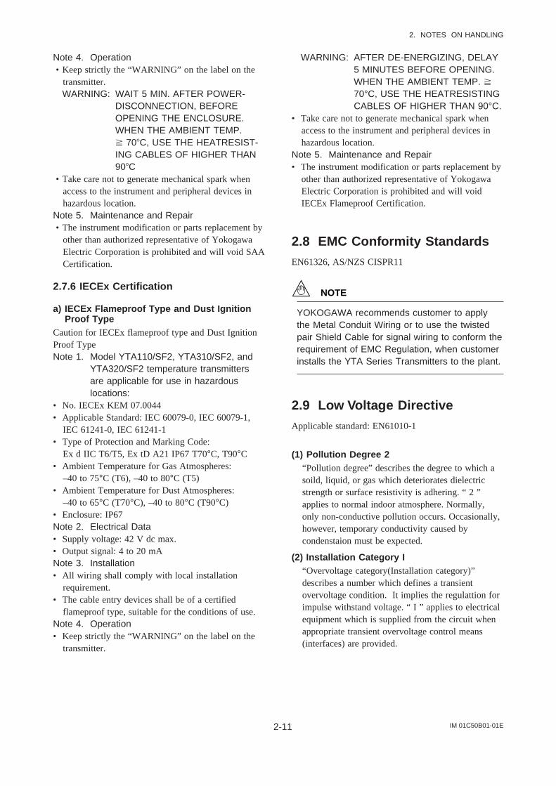
2.7.6 IECEx Certification
a) IECEx Flameproof Type and Dust IgnitionProof Type
Caution for IECEx flameproof type and Dust IgnitionProof TypeNote 1. Model YTA110/SF2, YTA310/SF2, and
YTA320/SF2 temperature transmittersare applicable for use in hazardouslocations:
• No. IECEx KEM 07.0044• Applicable Standard: IEC 60079-0, IEC 60079-1,
IEC 61241-0, IEC 61241-1• Type of Protection and Marking Code:
Ex d IIC T6/T5, Ex tD A21 IP67 T70°C, T90°C• Ambient Temperature for Gas Atmospheres:
–40 to 75°C (T6), –40 to 80°C (T5)• Ambient Temperature for Dust Atmospheres:
–40 to 65°C (T70°C), –40 to 80°C (T90°C)• Enclosure: IP67Note 2. Electrical Data• Supply voltage: 42 V dc max.• Output signal: 4 to 20 mANote 3. Installation• All wiring shall comply with local installation
requirement.• The cable entry devices shall be of a certified
flameproof type, suitable for the conditions of use.Note 4. Operation• Keep strictly the “WARNING” on the label on the
transmitter.
WARNING: AFTER DE-ENERGIZING, DELAY5 MINUTES BEFORE OPENING.WHEN THE AMBIENT TEMP. 70°C, USE THE HEATRESISTINGCABLES OF HIGHER THAN 90°C.
• Take care not to generate mechanical spark whenaccess to the instrument and peripheral devices inhazardous location.
Note 5. Maintenance and Repair• The instrument modification or parts replacement by
other than authorized representative of YokogawaElectric Corporation is prohibited and will voidIECEx Flameproof Certification.
2.8 EMC Conformity StandardsEN61326, AS/NZS CISPR11
NOTE
YOKOGAWA recommends customer to applythe Metal Conduit Wiring or to use the twistedpair Shield Cable for signal wiring to conform therequirement of EMC Regulation, when customerinstalls the YTA Series Transmitters to the plant.
2.9 Low Voltage DirectiveApplicable standard: EN61010-1
(1) Pollution Degree 2“Pollution degree” describes the degree to which asoild, liquid, or gas which deteriorates dielectricstrength or surface resistivity is adhering. “ 2 ”applies to normal indoor atmosphere. Normally,only non-conductive pollution occurs. Occasionally,however, temporary conductivity caused bycondenstaion must be expected.
(2) Installation Category I“Overvoltage category(Installation category)”describes a number which defines a transientovervoltage condition. It implies the regulattion forimpulse withstand voltage. “ I ” applies to electricalequipment which is supplied from the circuit whenappropriate transient overvoltage control means(interfaces) are provided.

IM 01C50B01-01E3-1
3. PART NAMES AND FUNCTIONS
3. PART NAMES AND FUNCTIONS
3.1 Part Names
F0301.EPSF0301.EPS
Amp. cover
LCD assembly(with indicator)
Burn out output directionsetting pin upon hardware failure
CPU assembly
Stud bolt
Name plate
Groundingterminal
Terminal cover
Groundingterminal
Wiring connector(input signal side)
Output signal terminal
Wiring connector(output signal side)
Input signal terminal
Tag plate
Lock screw(for CENELEC, SAA and TIIS flameproof type)
Built-in indicator display
Figure 3.1 Part Names

IM 01C50B01-01E3-2
3. PART NAMES AND FUNCTIONS
3.2 Setting the Hardware ErrorBurnout Change-over Switch
The temperature transmitter is equipped with a hard-ware error burnout function used to set the outputdirection upon hardware error, and a sensor burnoutfunction that sets the direction of the output in theevent of burnout of the temperature sensor. Whenfactory-shipped under normal conditions, the output ofboth hardware error burnout and sensor burnout are setto HIGH, but if suffix code /C1 is specified, thehardware error burnout is set to LOW (-5%) output,and sensor burnout is set to LOW (-2.5%) output,respectively. The setting of the direction of output fromburnout can be changed.
To change the direction of output arising from burnout,switch the setting pin on the CPU assembly (see Figure3.1 and Table 3.1). To change the direction of outputarising out of sensor burnout, a dedicated hand-heldterminal is required to rewrite the parameters withinthe transmitter. For details, refer to the separateinstruction manual, IM 01C50T01-01E “HARTProtocol” or IM 01C50T03-01E “BRAIN Protocol”.
Table 3.1 Output Direction Setting Pins for HardwareError Burnout
T0301.EPS
H
L
H
L
Pinposition
RemarkHardware errorburnoutdirection
HIGH
LOW
110% or more(21.6 mA DC)
-5% or less(3.2 mA DC)
Set to HIGH uponshipment from thefactory
Set to LOW whensuffix code /C1is provided
Hardware errorburnoutoutput
3.3 Built-in Indicator DisplayFunction
F0302.EPS
Output bar chart display
Communication protocol display
Operation mode display
Display of sensor type andnumber of wire connections
Unit display
Process variable display
Input display
Figure 3.2 Built-in Indicator Display Function
(1)Output bar chart displayThe output value is displayed in a bar chart. Resolutionof the bar chart is to the extent of 32 divisions (eachincrement is about 3.125%). If the output exceeds 0%or 100%, is lit. The bar chart can be toggled ON/OFF using the bar chart display parameter.
(2) Communication protocol displayThe indicator is on in accordance with each communi-cation protocol.
(3)Operation mode displayLit when each operation mode is activated.
M.D.: Lit when the multidrop mode of HART commu-nication specification is activated.
B.M.: Lit during burst mode transfer of HART commu-nication specification.
F.O.: Lit when manual mode is active.
W.P.: Lit when write protect status is active.
(4)Input displayIndicates the type of input in accordance with the valueshown in the column in Item (5).
Sns1: Meant to show the process variable allocated toSensor 1.
Sns2: Meant to show the process variable allocated toSensor 2. (Can be displayed only with theYTA320.) .
Term:Meant to show the temperature of the terminalbox of the temperature transmitter.
Avg: Meant to show the average of the processvariable allocated to Sensor1 and Sensor2. (Canbe displayed only with the YTA320.).
Dif: Meant to show the difference of the processvariable allocated to Sensor1 and Sensor2. (Canbe displayed only with the YTA320.)
(5)Process variable displayDisplays the process variable or output value. Thevalue is displayed down to the second decimal positionif the integer part is less than three digits, or down tothe first decimal position if the integer part is 4 digits.If the value is negative, the minus () sign is lit. Forprocess variables, the indicators for each item specifiedin the column of input display in Item (4) and the unitcolumn in Item (6) are lit. For output value, % or mAin the unit column in Item (6) is lit. When burnout ofthe temperature sensor is identified, or the temperaturetransmitter is found abnormal, an error code flashes.For a list of error codes, refer to “Error code table” inSection 6.4.

IM 01C50B01-01E3-3
3. PART NAMES AND FUNCTIONS
(6)Unit displayThe unit specified as the unit of process in the processvariable display column in Item (5) is lit. The outputdisplay is fixed to mA or %.
(7)Display of sensor type and number of wireconnections
Displays process variable/output items, the number ofsensor wiring connections and the multidrop address indot matrix (only applies to HART communication). Inthe event of hardware error, “FAIL” is displayed.
Process variable: To display the process variablevalue in the process variabledisplay in Item (5), display the typeof applicable process variable(“PV”, “SV”, “TV”).
Output display: To display the output value in theprocess variable display in Item(5), display “OUT”. During theoutput of sensor burnout, “Abn”and “OUT” are alternately displayed.
WIRE: Displays the number of wiringconnections. There are two wiringconnections for thermocoupleinput, while there are two to fourconnections for thermometerresistor; these are displayedalternately with the sensor type.The display can be hidden bysetting an applicable parameter.Note that the DIF and AVG displaydoes not allow the sensor type tobe displayed.
TYPE: Displays the type of sensor. Notethat the DIF and AVG display doesnot allow the sensor type to bedisplayed. If the sensor is custom-ordered, “Z1” and “Z2” aredisplayed.
Multidrop address: If the multidrop address is 1through 15 in HART communica-tion, the output display brings upthese addresses instead of displaying “OUT”.
Upon shipment from the factory, the indicator is set asfollows.
Table 3.2 Setting of Indicator upon Shipment from theFactory
T0302.EPS
Display location
Output bar chart display is on.
Sns1 is lit.
PV value and output value(mA) are alternately displayed.
The unit specified uponshipped from factory and mAare lit.
“PV” and “OUT” are displayedalternately.
Contents
Output bar chart display
Display of sensor type andnumber of wire connections
Unit display
Process variable display
Input display

IM 01C50B01-01E4-1
4. INSTALLATION
4. INSTALLATION
IMPORTANT
• When performing on-site pipe fitting work thatinvolves welding, use care to prevent outflow
of the welding current into the transmitter.• Do not use the transmitter as a foothold for
installation.
F0401.EPS
Horizontal Pipe Mounting Vertical Pipe Mounting
U-bolt nut
Spring washer
Horizontal pipemounting bracket
U-bolt
Wall Mounting
Note: Wall mounting bolts are user-supplied.
Transmitterfastening bolt
U-bolt nut
Vertical pipe mounting
bracket Transmitterfastening bolt
Spring washer
Spring washer
U-bolt
Bracketfastening bolt
Bracketfastening nut
• When using a horizontal pipe mounting bracket
• When using a vertical pipe mounting bracket
Figure 4.1 Mounting the Transmitter
• For details of choosing the installation location, referto the guidelines outlined in Section 2.4, “Choosingthe installation location”.
• The mounting bracket shown in Figure 4.1 is usedfor the transmitter and is installed on 50A (2B) pipe.It can be installed either on a horizontal pipe and avertical pipe or on a wall.
• To install the mounting bracket on the transmitter,torque the transmitter lock screw (1) to about 20 to30Nm.

IM 01C50B01-01E5-1
5. WIRING
5. WIRING
5.1 Notes on Wiring
IMPORTANT
• Apply a waterproofing sealant to thethreads of the connection port. (It is recom-mended that you use non-hardening sealantmade of silicon resin for waterproofing.)
• Lay wiring as far away as possible fromelectrical noise sources such as large trans-formers, motors and power supplies.
• Remove the wiring connection dust-capsbefore wiring.
• To prevent electrical noise, the signal cableand the power cable must not be housed inthe same conduit.
• The terminal box cover is locked by an Allenhead bolt (a shrouding bolt) on CENELEC,SAA and TIIS flameproof type transmitters.When the shrouding bolt is driven clockwiseby an Allen wrench, it is going in and coverlock is released, and then the cove can beopened by hands. See Subsection 6.3“Disassembly and Reassembly” for details.
5.2 Loop ConstructionThe YTA is a two-wire temperature transmitter thatuses the output power supply wiring and signal wiringalternately.
The transmission loop requires DC power. Connect thetransmitter with the distributor as shown in Figure 5.1or Figure 5.2.
For the transmission loop, the load resistance of thedistributor or other instrument to be installed in theloop and the lead wire must be within the range shownin Figure 5.3.
For details of communication requirements, refer to theadditional reference materials, IM 01C50T03-01E “YTASeries BRAIN Communication”, and IM 01C50T01-01E“YTA Series HART Communication”.
F0501.EPS
<Hazardous location> <Nonhazardous location>
+
Output signal
–
Distributor(power supply unit) Receiver
Input signal(thermocouple,RTD, mV, etc.)
Figure 5.1 Loop Construction (for General-use Type andFlameproof Type)
F0502.EPS
<Hazardous location> <Nonhazardous location>
+ Output signal
–
Distributor(power supply unit) Receiver
Safetybarrier
Input signal(thermocouple,RTD, mV, etc.)
Figure 5.2 Loop Construction (for Intrinsically SafeType)
600
250
10.5 16.4 24.7 42
Power supply voltage E (V DC)
R=0.0236E–10.5
F0503.EPS
Externalload
resistance
R()
Communicationapplicable range
BRAIN and HART
Figure 5.3 Relation between Power Supply Voltage andLoad Resistance
Note: For intrinsic safe explosion-proof type units, the internalresistance of the safety barrier is also included in the loadresistance.

IM 01C50B01-01E5-2
5. WIRING
CAUTION
When wiring, pay attention not to damage thecable and cores. All the cores of the cable musthave the sufficient insulation around them.
F0504.EPS
a. Cable connection to thermometer resistor(RTD), 3-wire
b. Power supply cable connection
STEP 1(1)
STEP 2(2)
Figure 5.4 Terminal Connection Pro cedure
The temperature sensor is to be connectedas shown in Figures 5.6 and 5.7.
F0505.EPS
Figure 5.5 Terminal diagram
5.3 Cable Selection
5.3.1 Input signal Cable Selection
A dedicated cable is used for connection between thetemperature sensor and the temperature transmitter.When a thermocouple is used as the temperaturesensor, a compensation wire must be used that itappropriate for the type of thermocouple (refer tocompensating cables for JIS C 1610/IEC584-3 thermo-couples). When a resistance temperature sensor (RTD)is used as the temperature sensor, 2-core/3-core/4-corecable must be used (refer to resistance thermometersensor JIS C 1604/IEC751). The terminal of thededicated cable is a 4 mm screw.
5.3.2 Output Signal Cable Selection
• With regard to the type of wire to be used forwiring, use twisted wires or cables with perfor-mance equivalent of 600V vinyl insulated cable(JIS C3307).
• For wiring in areas susceptible to electrical noise,use shielded wires.
• For wiring in high or low temperature areas, usewires or cables suitable for such temperatures.
• For use in an atmosphere where harmful gases orliquids, oil, or solvents are present, use wires orcables made of materials resistant to those sub-stances.
• It is recommended that a self-sealing terminal withinsulation sleeve (4-mm screw) be used for leadwire ends.
WARNING
If the YTA is TIIS flameproof and the ambienttemperature is 50°C or more, use an externalcable having a maximum allowable heat resis-tance of at least 70°C in consideration of theinstrument’s generation of heat or the cable’sself-heating.
5.4 Cable and Terminal Connec-tions
5.4.1 Input Terminal Connections
NOTE
It is recommended that the terminals be con-nected in the order of input terminal (1) andoutput terminal (2).

IM 01C50B01-01E5-3
5. WIRING
F0506.EPS
12345
12345
12345
12345
(–)
(+)
(B)
(A)
(B)
(A)
(B)
(B)
(A) (A)
(B)
Thermocouple andDC voltage
RTD and resistance(2-wire)
RTD and resistance(3-wire)
RTD(4-wire)
Sensor1(YTA110, YTA310)
Figure 5.6 YTA110 and YTA310 Input Terminal WireConnection Diagram
(B1)
(A1)12345
(–)
(+)12345
(B1)
(B1)12345
(–)
(+)12345 (+)
(A1)
(B2)
(B2)
(A2)
(A)
(B)
(B)(B2)
(A2)
12345
12345
12345
12345
(–)
(+)
(B)
(A)
(B)
(B)
(B)
(A)
(A) (A)
(B)
Thermocouple andDC voltage
RTD and resistance(3-wire)
Thermocouple +RTD and resistance
(3-wire)
RTD and resistance(2-wire)
2 input (YTA320)
Thermocouple andDC voltage
RTD and resistance(2-wire)
RTD and resistance(3-wire)
RTD(4-wire)
1 input (YTA320)
Figure 5.7 YTA320 Input Terminal Wire ConnectionDiagram
5.4.2 Output Terminal Connection
(1) Connection of output signal/power supplycable
Connect the output signal cable (shared with thepower supply cable) to the – terminal and the +terminal. For details, refer to Figure 5.2, “Loopconstruction”.
(2) Connection of wiring for field indicatorConnect the lead wire for the field indicator withthe – terminal and the C terminal.
Note: Use a field indicator with an internal resistance of 10W or less.
F0508.EPS
Field indicator
Powersupply –
–
++
Figure 5.8 Connection to Field Indicator
(3) Connection of check meterConnect the check meter with the – terminal andthe C terminal.The current signal of output signal 4 to 20 mA DCis output from the – terminal and the C terminal.
Note: Use a check meter with internal resistance of 10 or less.
F0509.EPS
Check meter
+
–
Powersupply
Figure 5.9 Check Meter Connection
IM 01C50B01-01E5-4
5. WIRING
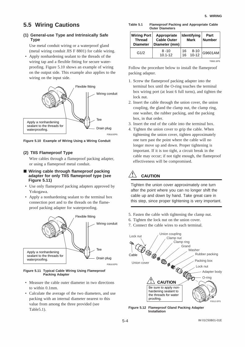
5.5 Wiring Cautions
(1) General-use Type and Intrinsically SafeType
Use metal conduit wiring or a waterproof gland(metal wiring conduit JIS F 8801) for cable wiring.
• Apply nonhardening sealant to the threads of thewiring tap and a flexible fitting for secure water-proofing. Figure 5.10 shows an example of wiringon the output side. This example also applies to thewiring on the input side.
F0510.EPS
Apply a nonhardeningsealant to the threads forwaterproofing.
Wiring conduit
Tee
Flexible fitting
Drain plug
Figure 5.10 Example of Wiring Using a Wiring Conduit
(2) TIIS Flameproof TypeWire cables through a flameproof packing adapter,or using a flameproof metal conduit.
Wiring cable through flameproof packingadapter for only TIIS flameproof type (seeFigure 5.11)
• Use only flameproof packing adapters approved byYokogawa.
• Apply a nonhardening sealant to the terminal boxconnection port and to the threads on the flame-proof packing adapter for waterproofing.
F0510.EPS
Apply a nonhardeningsealant to the threads forwaterproofing.
Wiring conduit
Tee
Flexible fitting
Drain plug
Figure 5.11 Typical Cable Wiring Using FlameproofPacking Adapter
• Measure the cable outer diameter in two directionsto within 0.1mm.
• Calculate the average of the two diameters, and usepacking with an internal diameter nearest to thisvalue from among the three provided (seeTable5.1).
Table 5.1 Flameproof Packing and Appropriate CableOuter Diameters
Wiring PortThread
Diameter
IdentifyingMark
PartNumber
G1/2 G9601AM
AppropriateCable Outer
Diameter (mm)
8 -1010.1-12
1616
8-1010-12
T0501.EPS
Follow the procedure below to install the flameproofpacking adapter.
1. Screw the flameproof packing adapter into theterminal box until the O-ring touches the terminalbox wiring port (at least 6 full turns), and tighten thelock nut.
2. Insert the cable through the union cover, the unioncoupling, the gland the clamp nut, the clamp ring,one washer, the rubber packing, and the packingbox, in that order.
3. Insert the end of the cable into the terminal box.4. Tighten the union cover to grip the cable. When
tightening the union cover, tighten approximatelyone turn past the point where the cable will nolonger move up and down. Proper tightening isimportant. If it is too tight, a circuit break in thecable may occur; if not tight enough, the flameproofeffectiveness will be compromised.
CAUTION
Tighten the union cover approximately one turnafter the point where you can no longer shift thecable up and down by hand. Take great care inthis step, since proper tightening is very important.
5. Fasten the cable with tightening the clamp nut.6. Tighten the lock nut on the union cover.7. Connect the cable wires to each terminal.
Adapter body
Rubber packingWasher
Packing box
GrandClamp ring
Clamp nutUnion coupling
Union cover
O-ring
Lock nut
Lock nut
Cable
CAUTIONBe sure to apply non-hardening sealant to the threads for water proofing.
F0512.EPS
Figure 5.12 Flameproof Gland Packing Adapterlnstallation

IM 01C50B01-01E5-5
5. WIRING
Flameproof metal conduit wiring• A seal fitting must be installed near the terminal
box connection port for a sealed construction.• Apply a nonhardening sealant to the threads of the
terminal box connection port, flexible metal conduitand seal fitting for waterproofing.
F0513.EPS
Non-hazardousarea
Hazardousarea
Flameproofheavy-gaugesteel conduit
Tee
Drain plug
Gas sealingdevice
Flameproof flexiblemetal conduit
Apply a nonhardeningsealant to the threads ofthese fittings forwaterproofing
Seal fitting
After wiring, impregnate the fittingwith a compound to seal tubing.
Figure 5.13 Typical Wiring Using Flameproof MetalConduit
5.6 GroundingGrounding is always required for the proper operationof transmitters. Follow the domestic electrical require-ments as regulated in each country. For a transmitterwith built-in lightning protector, grounding shouldsatisfy ground resistance of 10 or less.
Ground terminals are located on the inside and outsideof the terminal box. Either of these terminals may beused.
WARNING
For TIIS flameproof type and intrinsically safe,grounding should satisfy Class D requirements(grounding resistance, 100 or less).
F0511.EPS
Groundingterminal(Inside)
Groundingterminal(Outside)
Figure 5.14 Grounding Terminal

IM 01C50B01-01E6-1
6. MAINTENANCE
6. MAINTENANCE
6.1 GeneralEach component of this instrument is configured inunits to make maintenance easier.
This chapter contains disassembly and assemblyprocedures associated with calibration, adjustment andpart replacement required for maintenance of theaffected instrument.
IMPORTANT
1. Maintenance of this instrument should beperformed in a service shop where the neces-sary tools are provided.
2. Handling the CPU assemblySome of the parts contained in the CPUassembly are susceptible to static electricitydamage. Before performing maintenance, usea ground wrist band or other antistatic measures, and avoid touching the electroniccomponents and circuits with bare hands.When removed from the instrument, keep theCPU assembly in an antistatic bag.
6.2 CalibrationThis instrument is fully factory-tested and is guaran-teed for the intended accuracy, eliminating the need forcalibration. When calibration needs to be varified, thefollowing equipment and calibration procedure isrecommended.
6.2.1 Selection of Equipment for Calibra-tion
Table 6.1 lists the equipment required for calibration.The calibration equipment traceable to a verifyingagency standard should be used.
6.2.2 Calibration Procedure
To conduct calibration required to evaluate the uncer-tainty while using the instrument, follow the stepsbelow:
1. In accordance with the example wiring shown inFigure 6.1, connect each equipment and initiatewarm up. Lay wiring on the input side according tothe sensor to be used.
Table 6.1 Calibration Equipment List
T0601 EPS
Power supply
2792 type standardresistor(250 ±0.005%)
Voltmeter
Universalcalibrator
Variable resistor
SDBT, SDBStype distributor
Model 1271 digitalmultimeter(accuracy: ±0.002%)
Model 9100 type
Load resistance
4 to 20mA DC(Output voltage:26.5±1.5V, drop byinternal 250resistance included)
For 4 to 20mA DC
For 4 to 20mA DCsignal
For calibration ofDC voltage andthermocouple
For calibration ofthermometer resistor(RTD) input
Name Recommended Remark
279301 type 6-dialvariable resistor(accuracy: ±0.001%±2m)
F0601.EPS
12345
12345
(A)
(B)
(B)
(A)
a. Wiring of power supply and output
b. Example of wiring for thermocoupleor DC voltage input(when 1 input type is used)
+ Output signal
– Loadresistance
DC voltage generator
Voltmeter
c. Example of wiring for thermometerresistor 4-core type(when 1 input type is used)
Variable resistor
(+)(–)
Figure 6.1 Example of Wiring for Calibration Equipment
2. For DC voltage inputWith a voltage generator, deliver input signalscorresponding to 0, 25, 75, or 100% of the inputspan to the temperature transmitter. Measure theresulting input signal with the voltmeter (digitalmultimeter) and check the output value relative tothe input value.

IM 01C50B01-01E6-2
6. MAINTENANCE
3. For thermocouple inputSince this instrument is equipped with a referencejunction compensating function, use a referencejunction compensating function in universalcalibrator in order to compensate for this functionupon calibration. According to the referencemilivolt table for thermocouple, obtain milivoltcorresponding to 0, 25, 50, 75, or 100% of thespan, and use that power as the input value, thendeliver it from the universal calibrator to thetemperature transmitter. Measure the resultingoutput signal with the voltage meter (digitalmultimeter) and check the output value relative tothe input value.
4. Thermometer resistor (RTD)Using a thermometer resistor as input, calibration ofthe temperature transmitter is carried out via a 4-core wire connection.As defined the reference resistor value table of thethermometer resistor (RTD), obtain resistancevalues corresponding to 0, 25, 50, 75 or 100% ofthe span, and use the obtained resistance as theinput value, then deliver it to the temperaturetransmitter by means of a variable resistor. Measurethe resulting output signal with the voltmeter(digital multimeter) and check the output valuerelative to the input value.
5. In Steps 2 through 4, if the output signal deviatesfrom the given range of accuracy when a giveninput signal is delivered, adjust the output using thehandheld terminal. For details of how to adjust theoutput, refer to the additional references, “BRAINProtocol” IM 01C50T03-01E or “HART Protocol”IM 01C50T01-01E and the instruction manual foreach terminal.
6.3 Disassembly and AssemblyThis section details the procedure for part replacementor disassembly and assembly of each componentdepending on the maintenance process.
Before starting disassembly and assembly work, turnoff the power, and use a tool suited to the associatedwork.
Table 6.2 lists the tools required for disassembly andassembly of the instrument.
Table 6.2 Tools for Disassembly and Assembly
T0602.EPS
Tool name Quantity Remark
Phillips screwdriver 1Standard screwdriver 1Hexagonal wrench 1Crescent wrench 1Torque wrench 1Box wrench 1 For M10 screwBox screwdriver 1Forceps 1
CAUTION
Precautions for CENELEC, SAA and TIISFlameproof Type Transmitters
• For a withstand flameproof type transmitter, asa rule, move the transmitter to a non-hazardouslocation, then proceed with maintenance andrestore the instrument to the original condition.
• For a withstand CENELEC, SAA and TIISflameproof type transmitter, turn the lock bolt(hexagon socket bolt) clockwise with a wrenchfor hexagon head, unlock and remove thecover. When installing the cover, it is the mustto turn the lock bolt counterclockwise and lockthe cover (locked to a torque of 0.7 Nm).
• For a withstand flameproof type transmitter, inno case should the user be allowed to modifythe transmitter. Therefore, no user is allowed toadd a built-in indicator, or use the transmitterwith the indicator removed. Contact us for anymodification.
F0602.EPS
Terminal cover
Lock bolt
CPU assembly
Stud bolt
Mounting screw
Amp. Cover
LCD board(with indicator)
Figure 6.3 Mounting and Removal of Built-in Indicatorand CPU Assembly

IM 01C50B01-01E6-3
6. MAINTENANCE
6.3.1 Replacement of Built-in Indicator
Removal of built-in indicator1. Remove the cover.2. Loosen two mounting screws while using your hand
to support the built-in indicator.3. Remove the LCD assembly from the CPU assem-
bly. At this time, straighten and pull the LCDassembly forward so that the connector connectingthe CPU assembly and the LCD assembly is notdamaged.
Mounting the built-in indicatorIntegral Indicator can be installed in the followingthree directions.
F0603.EPS
Figure 6.4 Installation Direction of Indicator
1. Place the LCD assembly in desired direction overthe CPU assembly.
2. Align the mounting hole of the LCD assembly withthe stud bolt hole, and carefully insert the indicatorinto the connector in a straight manner so that theconnector is not damaged.
3. Tighten the two mounting screws that secure theindicator.
4. Install the cover.
6.3.2 Replacement of CPU Assembly
Removal of CPU assembly1. Remove the cover.2. Use a Phillips screwdriver to loosen the two screws.3. For a CPU assembly with a built-in indicator,
remove it as described in Section 6.3.1. Next loosenthe two stud bolts.
4. Pull the CPU assembly directly toward you.5. Remove the cable (with a brown connector attached
at the head).
NOTE
Use care not to apply excessive force to theCPU assembly during removal.
Mounting the CPU assembly1. Connect the cable with the CPU assembly.2. Align the pin on the base board with the connector
(black) of the CPU assembly, and insert the CPUassembly straight into the board.
IMPORTANT
Use care not to pinch the cable under the cover,and fully insert the cable into the case.
3. Loosen the two screws. If the unit includes a built-in indicator, install it as described in Section 6.3.1.
4. Mount the cover.
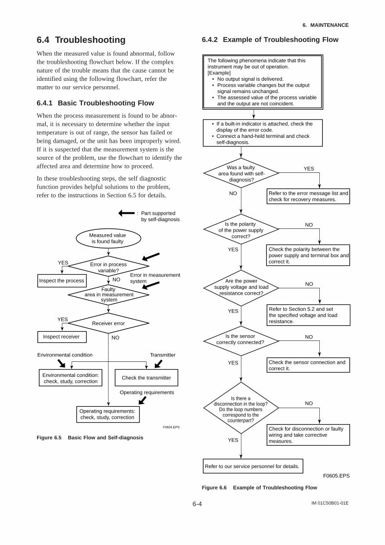
IM 01C50B01-01E6-4
6. MAINTENANCE
6.4 TroubleshootingWhen the measured value is found abnormal, followthe troubleshooting flowchart below. If the complexnature of the trouble means that the cause cannot beidentified using the following flowchart, refer thematter to our service personnel.
6.4.1 Basic Troubleshooting Flow
When the process measurement is found to be abnor-mal, it is necessary to determine whether the inputtemperature is out of range, the sensor has failed orbeing damaged, or the unit has been improperly wired.If it is suspected that the measurement system is thesource of the problem, use the flowchart to identify theaffected area and determine how to proceed.
In these troubleshooting steps, the self diagnosticfunction provides helpful solutions to the problem,refer to the instructions in Section 6.5 for details.
YES
YES
NO
NO
F0604.EPS
Measured valueis found faulty
Error in processvariable?
Faulty area in measurement
system
Receiver error
Operating requirements:check, study, correction
Check the transmitterEnvironmental condition:check, study, correction
Environmental condition
Operating requirements
Error in measurementsystem
Transmitter
Inspect receiver
Inspect the process
: Part supportedby self-diagnosis
Figure 6.5 Basic Flow and Self-diagnosis
6.4.2 Example of Troubleshooting Flow
F0605.EPS
YES
NO
NO
YES
NO
YES
NO
NO
YES
YES
Was a faulty area found with self-
diagnosis?
Is the polarity of the power supply
correct?
Are the powersupply voltage and load
resistance correct?
Is the sensorcorrectly connected?
Is there adisconnection in the loop?
Do the loop numberscorrespond to the
counterpart?
The following phenomena indicate that thisinstrument may be out of operation.[Example]
• No output signal is delivered.• Process variable changes but the output
signal remains unchanged.• The assessed value of the process variable
and the output are not coincident.
Refer to our service personnel for details.
• If a built-in indicator is attached, check the display of the error code.
• Connect a hand-held terminal and check self-diagnosis.
Refer to the error message list andcheck for recovery measures.
Check the polarity between thepower supply and terminal box andcorrect it.
Refer to Section 5.2 and setthe specified voltage and loadresistance.
Check the sensor connection andcorrect it.
Check for disconnection or faultywiring and take correctivemeasures.
Figure 6.6 Example of Troubleshooting Flow

IM 01C50B01-01E6-5
6. MAINTENANCE
Table 6.3 Problems, Causes and Countermeasures
Related ParameterObserved Problems Possible Cause Countermeasure
F10:LRV
F20:URV
J05:SNSR1 CLR
K05:SNSR2 CLR
L05:OUT CLR
G10:OUTPUT MODE
J05:SNSR1 CLR
K05:SNSR2 CLR
L05:OUT CLR
F10:LRV
F20:URV
H10:REVERSE OUT
H40:WRITE PROTCT
B10:PV is
B20:SV is
D10:SENSOR1 TYPE
E10:SENSOR2 TYPE
F40:BURN OUT
H20:SNSR BACKUP
B12:PV DAMPING
B13:DMP POINT
Check the range, and change the settings to make the span larger.
Clear the user adjustment (Sensor trim) value or set it to off.
Clear the user adjustment (output trim) value or set it to off.
Release manual mode. (Make the transmitter return to Automatic Mode)
Clear the user adjustment (Sensor trim) value or set it to off.
Clear the user adjustment (output trim) value or set it to off.
Set the correct value to URV and LRV.
Set the transmitter to normal output mode.
Release write protect.
Set Sensor1 as PV and Sensor2 as SV.
• Check the type and wire settings for Sensor1 and Sensor2.
• Check the connection of Sensor1 and Sensor2.
Check the Sensor Burnout setting.
Change the Sensor Backup function to “enable.”
Set correct value.
If output fluctuation is great, set a greater value for PV damping point than current setting. (Initial setting is “2%” of output)
Span is too narrow.
Input adjustment by user was not corrctly done.
Output adjustment by user was not correctly done.
The transmitter is in manual (test output) mode.
Input adjustment by user was not corrctly done.
Output adjustment by user was not correctly done.
LRV is greater than URV.
The transmitter is set to reversed output mode.
The transmitter is in write protect status.
Settings of Process Variables are not correct.
Configuration of Sensor1 and Sensor2 is not correct.
Sensor Burnout is set to “off.”
Sensor backup mode is not enabled.
Damping time constant is set to “0 second.”
Setting for “PV damping point” is too small.
Output fluctuates greatly.
Transmitter outputs fixed current.
Output is reversed. (See note 1)
Parameters cannot be changed.
Sensor backup function doesn’t work correctly.
Output damping doesn’t work.
T0603.EPS
PV LRV (4)
PV URV (5)
Snsr1 Trim Act (123312)
Snsr2 Trim Act (123322)
D/A Clr to Default (12343)
Loop test (122)
Snsr1 Trim Act (123312)
Snsr2 Trim Act (123322)
D/A Clr to Default(12343)
PV LRV (4)
PV URV (5)
Chng wrt Protect (Hot key)
PV is (11211)
SV is (11212)
Snsr1 config (134)
Snsr2 config (135)
Sensor barnout (14315)
Snsr backup (14141)
PV damp (1322)
PV damp point (1323)
(HART protocol)(BRAIN protocol)
Note 1: If the reversed output is desired and necessary setting was done by user, it is not considered as a problem.

IM 01C50B01-01E6-6
6. MAINTENANCE
6.5 Integral Indicator and ErrorDisplay
For temperature transmitters equipped with an integralindicator, errors in the temperature sensor or thetransmitter cause an integral indicator to call up theapplicable error code. Table 6.4 lists the error codesand the associated corrective actions.
Table 6.4 List of Error Codes
Indicator BT200 display Cause Output operation upon error Action
N/A Good
Er-01 Output Too Low
Er-02 Output Too High
Er-03 Sensor1 Failure
Er-04 Sensor2 Failure (YTA320 only)
Er-05 S1 Signal Error
Er-06 S2 Signal Error (YTA320 only)
Er-07 Amb Temp Low
Er-08 Amb Temp High
Er-09 Sns Backup Start (YTA320 only)
Er-10 Illegal PV MAP
Er-11 Term Sns Failure
Er-12 EEPROM Failure
Er-13 CPU Failure
Er-14 AD Conv Failure
Er-15 Reverse Cal Fail
Input value is lower than the PV low range value.
Input value is higher than the PV upper range value.
Sensor1 fails or disconnects from the terminal block.
Sensor2 fails or disconnects from the terminal block.
Sensor1 input value greatly exceeds the sensor measurement range. Sensor type setting or connection polarity may be incorrect.
Sensor2 input value greatly exceeds sensor measurement range. Sensor type setting or connection polarity may be incorrect.
The ambient temperature exceeds the lower ambient temp limit and the specified accuracy cannot be achieved.
The ambient temperature exceeds the upper ambient temp limit and the specified accuracy cannot be achieved.
Sensor backup mode is in effect.
There is a problem with the PV mapping settings.
Terminal block temperature sensor failed.
EEPROM failed.
Output side hardware failure.
Input circuit hardware failure.
Confirmation Calculation result is bad.
Output goes to minimum value(–2.0%).
Output goes to maximum value(105%).
If sensor1 is set as PV, the burnout value is output. When sensor backup mode is set in YTA320, sensor2 input is used as output.
If sensor2 is set as PV, or sensor backup mode is in effect, sensor burnout value is output.
Output goes to minimum value(–2.0%) or maximum value(105%).
Output goes to minimum value(–2.0%) or maximum value(105%).
Continues to operate and output.
Continues to operate and output.
Sensor2 input is used as output. If sensor2 also fails, the transmitter operate with burnout settings.
Output status immediately before error is retained (HOLD).
Operation and output continues.
The output goes to the value set by the hardware failure mode jumper.
The output goes to the value set by the hardware failure mode jumper.The output goes to the value set by the hardware failure mode jumper.The output goes to the value set by the hardware failure mode jumper.
Check the LRV setting and adjust.
Check the URV setting and adjust.
• Check sensor for damage.• Check terminal connection.• If sensor backup mode is set,
refer to “Er-09”.
• Check sensor for damage.• Check terminal connection.• If sensor backup mode is set,
repair wiring or replace damaged sensors.
• Check sensor connections.• Check the sensor type
selected.
• Check sensor connections.• Check sensor type selected.
Use a heater to raise the ambient temperature, or reset to a higher level.
Take enough distance from the source of heat, or reset to a lower level.
Restore the status of sensor1 to normal and Enable sensor1 return parameters, or turn the power ON again.
Check the setting for PV mapping and correct the setting.
Contact our service personnel.
Contact our service personnel.
Contact our service personnel.
Contact our service personnel.
Contact our service personnel.
T0604.EPS

IM 01C50B01-01E7-1
7. GENERAL SPECIFICATIONS
7. GENERAL SPECIFICATIONS
7.1 Standard SpecificationsFor the specifications of Fieldbus communication typemarked with (), refer to IM 01C50T02-01E.
Input signal:Input points: YTA110; 1, YTA310; 1,
YTA320; 2Thermocouple: J, K, E, T, R, S, B, N
(T/C) (JIS/IEC584), L, U(DIN43710), W3, W5(ASTM988)
Thermometer resistor: Pt100, Pt200, Pt500(RTD) (IEC751), JPt100(JIS),
Cu, Ni1202/3/4-wire
DC voltage: mVResistance: Resistor 2/3-wire
Input signal source resistance:1k or lower (at thermocouple, DC voltageinput)
Input lead wire resistance:10/1-core or less (with thermometer resistor,resistance input)
Output():Two wire 4 to 20 mA DCOutput range: 3.68 mA to 20.8 mA
Measuring range:Refer to Table 7.1.
Power supply voltage():For general use type;
10.5 to 42 VDCWith lightning protection (Optional code A);
10.5 to 32 VDCFor intrinsically safe, Type n, non-incendive ornon-sparking type;
10.5 to 30 VDC
Communication line conditions():Power supply voltage; 16.4 to 42 VDCLoad resistance; 250 to 600 (including cableresistance)For relation between power supply voltage andload resistance, refer to Figure 5.3.Maximum line length; 2 km when CEV cable isused.Load resistance; 0.22 µF or lessLoad inductance; 3.3 mH or less
Spacing to power line;Output signal line; 15 cm or longer (avoid
parallel wiring)Input signal line; 100 cm or longer (avoidparallel wiring)
Input impedance of receiver connected toreceiver resistance; 10 k or higher (at 2.4 kHz)
Accuracy():YTA110;
A/C conversion accuracy + D/A conversionaccuracy (Refer to Table 7.1) or ±0.1%,whichever is greater. For thermocouple input,above plus reference junction compensationaccuracy.
YTA310, YTA320;A/C conversion accuracy + D/A conversionaccuracy (Refer to Table 7.1) For thermocoupleinput, above plus reference junction compensa-tion accuracy.
Reference junction compensation accuracy:±0.5°C (±0.9°F)
Ambient temperature:–40 to 85°C (–40 to 185°F) . . . general type–30 to 80°C (–1 to 176°F) . . . . with Integralindicator
Ambient temperature effect per 10°C change() :YTA110;
± 0.1% or ± (Temperature Coefficient/span),whichever is greater (refer to Table 7.2)
YTA310, YTA320;A/D conversion temperature factor + D/Aconversion temperature factor (refer to Table7.3)
StabilityRTD:
!0.1% of reading or !0.1°C per 2 years,whichever is greater at 23!2°C.
T/C:!0.1% of reading or !0.1°C per year,whichever is greater at 23!2°C.
5 Year StabilityRTD:
!0.2% of reading or !0.2°C,whichever is greater at 23!2°C.
T/C:!0.4% of reading or !0.4°C,whichever is greater at 23!2°C.

IM 01C50B01-01E7-2
7. GENERAL SPECIFICATIONS
Ambient humidity:5 to 100%RH at 40°C (104°F)
Effect of supply voltage fluctuation:±0.005%/V
Insulation:Input/output insulated at 500 V DC
Mounting:Mounted on 2B pipes and wall
Degrees of Protection:IP67, NEMA 4X, JIS C0920 immersion proof
Electrical connection:Refer to “Model and Specification Codes”.
Case and cover:Aluminum alloy casting
Painting:Polyurethane resin baked finishDeep sea moss green (equivalent of Munsell0.6GY3.1/2.0)
Integral indicator (option):LCD digital indicator (5-digit display)Output bar graph; 0 to 100% display
Damping constant:0 to 99 seconds (integer range that can be set)
Sensor burnout (Output Signal Code D&E) :High (110%, 21.6 mA DC) or Low (–2.5%, 3.6mA DC)
Weight:1.2 kg; without built-in indicator (without mount-ing bracket)1.4 kg; with Integral indicator (without mountingbracket)
EMC compliant standard: , EN61326, AS/NZS CISPR11

IM 01C50B01-01E7-3
7. GENERAL SPECIFICATIONS
Table 7.1 Input Type, Measurement Range and Accuracy
Sensor TypeReference Measurement Range Minimum Span
Accuracy
Standard (Recommended) Input range A/D Accuracy D/AC F C F C F Accuracy
T/C
B 100 to 1820 212 to 3308
100 to 300 212 to 572 ± 3.0 ± 5.4
300 to 400 572 to 752 ± 1.0 ± 1.8
400 to 1820 752 to 3308 ± 0.75 ± 1.35
E -200 to 1000 -328 to 1832-200 to -50 -328 to -58 ± 0.35 ± 0.63
-50 to 1000 -58 to 1832 ± 0.16 ± 0.29
J
IEC584
-200 to 1200 -328 to 2192-200 to -50 -328 to -58 ± 0.40 ± 0.72
25 C
-50 to 1200 -58 to 2192 ± 0.20 ± 0.36
K -200 to 1372 -328 to 2502
(45 F)
-200 to -50 -328 to -58 ± 0.50 ± 0.90
-50 to 1372 -58 to 2502 ± 0.25 ± 0.45
N -200 to 1300 -328 to 2372-200 to -50 -328 to -58 ± 0.80 ± 1.44
-50 to 1300 -58 to 2372 ± 0.35 ± 0.63
R -50 to 1768 -58 to 3214
-50 to 0 -58 to 32 ± 1.0 ± 1.8
0 to 100 32 to 212 ± 0.80 ± 1.44
± 0.02%
100 to 600 212 to 1112 ± 0.60 ± 1.08
of span
600 to 1768 1112 to 3214 ± 0.40 ± 0.72
S -50 to 1768 -58 to 3214
-50 to 0 -58 to 32 ± 1.0 ± 1.8
0 to 100 32 to 212 ± 0.80 ± 1.44
100 to 600 212 to 1112 ± 0.60 ± 1.08
600 to 1768 1112 to 3214 ± 0.40 ± 0.72
T -200 to 400 -328 to 752-200 to -50 -328 to -58 ± 0.25 ± 0.45
-50 to 400 -58 to 752 ± 0.14 ± 0.25
W3 0 to 2300 32 to 4172
0 to 400 32 to 752 ± 0.80 ± 1.44
400 to 1400 752 to 2552 ± 0.50 ± 0.90
1400 to 2000 2552 to 3632 ± 0.60 ± 1.08
ASTM 2000 to 2300 3632 to 4172 ± 0.90 ± 1.62
W5
E988
0 to 2300 32 to 4172
0 to 400 32 to 752 ± 0.70 ± 1.26
400 to 1400 752 to 2552 ± 0.50 ± 0.90
1400 to 2000 2552 to 3632 ± 0.70 ± 1.26
2000 to 2300 3632 to 4172 ± 0.90 ± 1.62
L -200 to 900 -328 to 1652-200 to -50 -328 to -58 ± 0.30 ± 0.54
DIN43710-50 to 900 -58 to 1652 ± 0.20 ± 0.36
U -200 to 600 -328 to 1112-200 to -50 -328 to -58 ± 0.50 ± 0.90
-50 to 600 -58 to 1112 ± 0.25 ± 0.45
RTD
Pt100 -200 to 850 -328 to 1562 -200 to 850 -328 to 1562 ± 0.14 ± 0.25
Pt200 IEC751 -200 to 850 -328 to 1562
10 C
-200 to 850 -328 to 1562 ± 0.30 ± 0.54
Pt500 -200 to 850 -328 to 1562
(18 F)
-200 to 850 -328 to 1562 ± 0.20 ± 0.36
JPt100 JIS C1604
SAMA RC21-4
-200 to 500 -328 to 932 -200 to 500 -328 to 932 ± 0.16 ± 0.29
-70 to -40 -94 to -40 ± 1.35 ± 2.43
-40 to 150 -40 to 302 ± 1.0 ± 1.8Cu -70 to 150 -94 to 302
mV -10 to 100 [mV] 3 [mV] ± 12 [µ V]
ohm 0 to 2000 [Ω] 20 [Ω] ± 0.35 [Ω]T0701.EPS
Ni120 -70 to 320 -94 to 608 -70 to 320 -94 to 608 ± 0.11 ± 0.19
Table 7.2 YTA110 Effect of Ambient Temperature
Sensor Type
T/C B
T07021.EPS
Temperature Coefficient
Thermocouples E, J, K, N, T, L, U
Thermocouples R, S, W3, W5
100C " Reading < 300C
300C " Reading
RTD
mV
ohm
0.08C + 0.02% of abs.reading
0.25C + 0.02% of abs.reading
1C + 0.02% of abs.reading
0.5C + 0.02% of abs.reading
0.08C + 0.02% of abs.reading
0.002 mV + 0.02% of abs.reading
0.1 + 0.02% of abs.reading
Note1: Ambient Temperature Effect per 10°C change is !0.1% or !(temperature coefficient/span), whichever is greater.Note2: The “abs.reading” on Table7.2 means the absolute value of the reading in °C. Example of abs reading;
When the temperature value is 250 Kelvin, abs reading is 23.15, absolute (250273.15).
Example of Ambient Temperature Effect; Conditions; 1) Input Sensor:Pt100 2) Calibration Range:100 to 100°C 3) Reading value: 50°C Ambient Temperature Effect per 10°C; Temperature Coefficient/Span =(0.08°C#0.02/100$|50°C|)/100°C(100°C)= 0.00045 → 0.045% Therefore, Ambient Temperature Effect is !0.1%/10°C
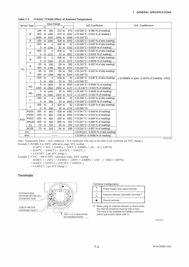
IM 01C50B01-01E7-4
7. GENERAL SPECIFICATIONS
Table 7.3 YTA310, YTA320 Effect of Ambient Temperature
Sensor TypeInput Range
A/D Coefficient D/A CoeffieicientC F
T/C
B212 to 572 ± ( 0.530 C0.080 % of reading) 572 to 1832 ± ( 0.350 C0.021 % of reading )
1832 to 3308 ± ( 0.140 C) E -328 to 1832 ± ( 0.035 C#0.042 % of abs.reading)
J-328 to 32 ± ( 0.039 C#0.020 % of abs.reading)
32 to 2192 ± ( 0.039 C#0.0029 % of reading)
K-328 to 32 ± ( 0.046 C#0.020 % of abs.reading)
32 to 2502 ± ( 0.046 C#0.0054 % of reading)
N-328 to 32 ± ( 0.054 C#0.010 % of abs.reading)
± 0.0088% of span#0.007% of (readingLRV)
32 to 2372 ± ( 0.054 C#0.0036 % of reading)
R-58 to 392 ± ( 0.210 C0.032 % of abs.reading)392 to 3214 ± ( 0.150 C)
S-58 to 392 ± ( 0.210 C0.032 % of abs.reading)392 to 3214 ± ( 0.150 C)
T-328 to 32 ± ( 0.046 C0.036 % of abs.reading)
32 to 752 ± ( 0.046 C)
W332 to 2552 ± ( 0.100 C#0.0040 % of reading)
2552 to 4172 ± ( -0.130C#0.020 % of reading)
W532 to 2552 ± ( 0.100 C#0.0040 % of reading)
2552 to 4172 ± ( -0.120C#0.020 % of reading)
L-328 to 32 ± ( 0.039 C#0.020 % of abs.reading)
32 to 1652 ± ( 0.039 C#0.0029 % of reading)
U-328 to 32 ± ( 0.046 C#0.036 % of abs.reading)
32 to 1112 ± ( 0.046 C)
RTD
Pt100 -328 to 1562 ± ( 0.047 C#0.009 % of reading) Pt200 -328 to 1562 ± ( 0.065 C#0.012 % of reading)
Cu ± ( 0.320 C#0.120 % of reading)-94 to 302
mV ± (0.001mV#0.0043 % of abs.reading) ohm ± ( 0.040 #0.0088 % of reading)
T07022.EPS
100 to 300300 to 1000
1000 to 1820-200 to 1000-200 to 0
0 to 1200-200 to 0
0 to 1372-200 to 0
0 to 1300-50 to 200200 to 1768-50 to 200200 to 1768
-200 to 00 to 4000 to 1400
1400 to 23000 to 1400
1400 to 2300-200 to 0
0 to 900-200 to 0
0 to 600-200 to 850-200 to 850
-70 to 150
Pt500 JPt100
-328 to 1562 ± ( 0.047 C#0.009 % of reading)-328 to 932 ± ( 0.047 C#0.009 % of reading)
-200 to 850-200 to 500
Ni120 -94 to 608 ± ( 0.016 C#0.007 % of reading)-70 to 320
Note: Temperature Effect = A/D coeffieicnt + D/A coefficient (The data in the table is the coeffcient per 10C change.)Example 1; Pt100, 0 to 200C calibration range, 50C reading
(0.047C # 50C $ 0.009%) # [200C $ 0.0088% # (50 0) $ 0.007%]= (0.047C # 0.0045C) # (0.0176C # 0.0035C )= ± 0.0726C [ per 10C change ]
Example 2; T T/C, 100 to 100C calibration range, 250C reading (0.046C # | 250C | $ 0.036%) # 200C $ 0.0088% # [250 (100)] $ 0.007%= (0.046C # 0.018C) # (0.0176C # 0.0035C )= ± 0.0851C [ per 10C change ]
Terminals
F0702.EPS
Power Supply and output terminal
External Indicator (ammeter) terminal *2
Ground terminal
Terminal Configuration
CommunicationTerminals (BT200 etc.)Connection hook
CHECK METERConnection hook *2
*2: When using an external indicator or check meter, the internal resistance must be 10Ω or less. The hook is not available for Fieldbus communi- cation type(output signal code F).M10$1.5 12-deep female
for mounting bracket

IM 01C50B01-01E7-5
7. GENERAL SPECIFICATIONS
Factory setting ()
T0705.EPS
Tag No.
Input sensor type
Lower bound of calibration range
Upper bound of calibration range
Unit of calibration range
Damping constant
Sensor burnout
Output when transmitter fails
Left blank if not specified in order
“Pt100, 3-wire” if not specified in order
“0” if not specified in order
“100” if not specified in order
“°C” if not specified in order
2 seconds
High side (110%, 21.6 mA DC) *1
High side (110%, 21.6 mA DC) *2
*1: When option code C1 is specified, Low takes effect (–2.5%, 3.6mADC).*2: When option code C1 is specified, Low takes effect (–5%, 3.2mADC or less).
7.2 Model and Suffix Codes
Model Basic Specification Codes Description
YTA110YTA310YTA320
Temperature transmitter (1 input type)High precision temperature transmitter (1 input type)High precision temperature transmitter (2 input type)
Outputsignal
–D . . . . . . . . . . . . . . . . . . . .–E . . . . . . . . . . . . . . . . . . . .–F . . . . . . . . . . . . . . . . . . . .
4 to 20mA DC output, BRAIN communication type4 to 20mA DC output, HART communication typeFOUNDATION Fieldbus communication type *1
A . . . . . . . . . . . . . . . . . Always A
Electricalconnection
0 . . . . . . . . . . . . . . .2 . . . . . . . . . . . . . . .3 . . . . . . . . . . . . . . .4 . . . . . . . . . . . . . . .
G1/2 female1/2 NPT femalePg13.5 femaleM20 female
Built-in indicator D . . . . . . . . . . . .N . . . . . . . . . . . .
Digital indicatorNone
Mounting bracket B . . . . . . . . . SUS304 Stainless steel 2-inch horizontal pipe mounting *2SUS304 Stainless steel 2-inch vertical pipe mounting *2None
D . . . . . . . . .
Additional specifications / Additional specificationsT0703.EPS
. . . . . . . . . . . . . . . . . . . . . .
. . . . . . . . . . . . . . . . . . . . . .
. . . . . . . . . . . . . . . . . . . . . .
—
*1: Applicable for YTA320 only.*2: Use bolts for wall mounting.
N . . . . . . . . .
7.3 Optional Specifications
Failure alarm up-scale: output status at CPU failure and hardware error is 110%, 21.6 mA or more.Sensor burnout is also set to ‘High’: 110%, 21.6 mA
C3
Failure alarm down-scale: output status at CPU failure and hardware error is –5%, 3.2 mA or less.Sensor burnout is also set to ‘Low’: –2.5%, 3.6 mA
Addition of Degree F and Degree R unit
Output signal low-side: –5 %, 3.2 mA DC or less.Sensor burnout is also set to ‘Low’: –2.5 %, 3.6 mA DC
Housing Material: SCS14A Stainless steel
Epoxy resin coating
P7
P1P2
E1D2
C2
C1
A
X1Munsell renotation code: NI1.5 BlackMunsell renotation code: 7.5BG4/1.5, Jade green
Power supply voltage: 10.5 to 32 V DCAllowable current: Max. 6000A(1$40s), repeating 1000A(1$40s) 100 times
Metallic silver
Munsell renotation code: 7.5R4/14 Red
$
Sensor matching function*2
RTD Sensor matching function CM1
PR
NAMUR NE43 compliant*2
Item Descriptions
Painting
Lightning protector
Code
Output signal low-side inTransmitter failure*2
Description into “Descriptor” parameter of HART protocol.(max. 16 characters)
CA Data Configuration*2
Stainless Steel Housing*1
Calibration Unit
Output signal limits:3.8 mA to 20.5 mA
Amplifier cover only
Amplifier and Terminal covers
Color change
Coating change
T0704.EPS
YTA
110
YTA
310
YTA
320
*1 : Not applicable with other option codes, except for A, C1, D2 and CM1.*2 : Not applicable for output signal code F.

IM 01C50B01-01E7-6
7. GENERAL SPECIFICATIONS
[For Explosion Protected Types]For FOUNDATION Fieldbus explosion protected type, see IM 01C50T02-01E.
CENELEC ATEX (KEMA) Intrinsically safe, Flameproof approval and Type n combination [Intrinsically safe approval]
Applicable standard: EN 50014, EN 50020, EN 50284 Certificate: KEMA 02ATEX1026XII 1G EEx ia IIC T4,T5 Ambient Temerature: -40 to 70°C for T4, -40 to 50°C for T5Supply/Output circuit: Ui=30V, Ii=165mA, Pi=900mW, Ci=20nF, Li=660HInput circuit: Uo=8.6V, Io=30mA, Po=70mW, Co=3F, Lo=20mHElectrical Connection: 1/2 NPT female and M20 female*1
[Flameproof and Dust Ignition Proof Approval]Applicable Standard: EN 60079-0, IEC 60079-1, EN 61241-0, EN 61241-1Certificate: KEMA 07ATEX0130II 2G Ex d IIC T6/T5, II 2D Ex tD A21 IP67 T70°C, T90°CAmbient Temperature for Gas Atmospheres: -40 to 75°C for T6, -40 to 80°C for T5Ambient Temperature for Dust Atmospheres: -40 to 65°C for T70°C, -40 to 80°C for T90°CEnclosure: IP67Electrical Connection: 1/2 NPT female and M20 female*1
[Type n approval]Applicable standard: EN60079-15 Referential standard: IEC60079-0, IEC60079-11 II 3G EEx nL llC T4, T5 Ambient Temperature: -40 to 70C for T4, -40 to 50C for T5Supply/Output circuit: Ui=30V, Ci=20nF, Li=660HInput circuit: Uo=8.6V, Io=30mA, Po=70mW, Co=3F, Lo=20mH
Electrical Connection: 1/2 NPT female and M20 female*1
CENELEC ATEX(KEMA)
Factory Mutual (FM)
Item Descriptions Code
KU2
FM Explosionproof approvalApplicable standard: FM 3600, FM 3615, FM 3810, NEMA250Explosionproof Class I, Division 1, Groups A, B, C and D;Dust-ignitionproof for Class II/III, Division 1, Groups E, F and G.“FACTORY SEALED, CONDUIT SEAL NOT REQUIRED.” Enclosure Rating: NEMA 4X Temperature Class: T6 Ambient Temperature: -40 to 60C (-40 to 140F)Electrical Connection: 1/2 NPT female*2
FM Intrinsically safe, non-incendive and Explosionproof approval combination*3
[Intrinsically safe/non-incendive approval]Applicable standard: FM 3600, FM 3610, FM 3611, FM 3810Intrinsically safe for Class I, II, III Division 1 Groups A, B, C, D, E, F and G.Non-incendive for Class I, II, Division 2 Groups A, B, C, D, E, F and G Class III, Division 1.Enclosure Type: 4X Temperature Class: T4 Ambient Temperature: -40 to 60C (-40 to 140F)Supply: Vmax=30V, Imax=165mA, Pmax=0.9W, Ci=18nF, Li=730HSensor: Voc=9V, Isc=40mA, Po=90Mw, Ca=1F, La=10mH
[Explosionproof approval]Applicable standard: FM 3600, FM 3615, FM 3810, NEMA250Class I, Division 1, Groups A, B, C and D.;Dust-ignitionproof for Class II/III, Division 1, Groups E, F and G."FACTORY SEALD, CONDUIT SEAL NOT REQUIRED." Enclosure Ratings: NEMA4XTemperature Class: T6 Ambient Temperature: -40 to 60C (-40 to 140F)Electrical Connection: 1/2NPT female*2
FF1
FU1
*1 : Applicable for Electrical Connection Code 2 and 4.*2 : Applicable for Electrical Connection Code 2.*3 : Not applicable for Output Signal Code F.
T0706-1.EPS
CSA Intrinsically safe, non-incendive and Explosionproof approval combination*3
[Intrinsically safe/non-incendive approval]Applicable standard: C22.2 No0, C22.2 No0.4, C22.2 No25, C22.2 No94, C22.2 No142, C22.2 No157, C22.2 No213 Certificate: 172608-0001053837Intrinsically safe for Class I, Division 1, Groups A, B, C and D; Class II, Division 1, Groups E, F and G; Class III, Division 1:Non-incendive for Class I, Division 2, Groups A, B, C and D; Class II, Division 2, Groups E, F and G; Class III, Division 1:Enclosure Type 4X Temperature Class: T4, Ambient Temperature: -40 to 60C,Supply: Vmax=30V, Imax=165mA, Pmax=0.9W, Ci=18nF, Li=730HSensor input: Voc=9V, Isc=40mA, Po=0.09W, Ca=1F, La=10mHElectrical Connection: 1/2 NPT female*1
[Explosionproof approval]Applicable standard: C22.2 No0, C22.2 No0.4, C22.2 No25, C22.2 No30, C22.2 No94, C22.2 No142, C22.2 No157, C22.2 No213, C22.2 No1010.1 Certificate: 1089576Explosionproof Class I, Div.1, Groups B, C and D, Class II, Groups E, F and G, Class III. For Class I, Div.2 Locations “FACTORY SEALED, CONDUIT SEAL NOT REQUIRED”Enclosure Type 4X Temperature Class: T4 Ambient Temperature: -40 to 60CElectrical Connection: 1/2 NPT female*1
Canadian StandardsAssociation (CSA)
CU1

IM 01C50B01-01E7-7
7. GENERAL SPECIFICATIONS
Japanese Industrial Standards (TIIS)
Item Descriptions Code
TIIS Flameproof approvalEx ds IIC T6 X Amb. Temp.: -20 to 60C
Attached flameproof packing adapter*4
Electrical connection: G1/2 femaleApplicable cable: O.D. 8.5 to 11 mm
JF3
SF2
G111 pc.
G122 pc.
*4 : If cable wiring is to be used to a TIIS flameproof type transmitter, do not fail to add the YOKOGAWA-assured flameproof packing adapter.*5 : Applicable for Electrical connection code 2, 3 and 4.*6 : Applicable only for Australia, New Zealand area.
T0706-2.EPS
Standards Association of Australia (SAA)
SAA Intrinsically safe, non-sparking and Flameproof approval combination[Intrinsically safe and non-sparking]
Applicable standard: AS2380.1, AS2380.7, AS2380.9 Certificate: AUS Ex 3652XEx ia IIC T4 (Tamb=70C) IP66/67, Ex n IIC T4 (Tamb=70C), IP66/67 Input parameters: Ui=30V, Ii=165mA, Pi=0.9W Output parameters: Uo=8.6V, Io=30mA, Po=62mW, Co=1F
[Flameproof approval]Applicable standard: AS2380.1, AS2380.2 Certificate: AUS Ex 3640Ex d IIC T6 (Tamb=75C) IP66/67
Electrical connection: 1/2 NPT female, Pg13.5 female and M20 female*5
IECEx Scheme*6
ECEx Flameproof and Dust ignition proof ApprovalApplicable Standard: IEC 60079-0, IEC 60079-1, IEC 61241-0, OEC 61241-1Certificate: IECEx KEM 07.0044Ex d IIC T6/T5, Ex tD A21 IP67 T70°C, T90°CAmbient Temperature for Gas Atmospheres: -40 to 75°C (-40 to 167°F) for T6,-40 to 80°C (-40 to 176°F) for T5Ambient Temperature for Dust Atmospheres: -40 to 65°C (-40 to 149°F) for T70°C, -40 to 80°C (-40 to 176°F) for T90°CEnclosure: IP67Electrical Connection: 1/2 NPT female and M20 female
SU1

IM 01C50B01-01E7-8
7. GENERAL SPECIFICATIONS
7.4 Dimensions
65.4(2.57)
With Indicator(Optional)
Unit: mm (Approx. inch)
Tag Plate
Terminal CoverElectrical Connection(Output signal)
Electrical Connection(Output signal)
Electrical Connection(Input signal)
Electrical Connection(Input signal)
Ground Terminal
Horizontal Pipe Mounting Bracket(Optional)
2-inch pipe, ø60.5(ø2.38)
2-inch pipe, ø60.5(ø2.38)
18.5(0.73)
46(1.81) 65(2.56)
ø93(3.66)
65.4(2.57)
Tag Plate
Terminal Cover
Ground Terminal
Vertical Pipe Mounting Bracket(Optional)
18.5(0.73)
46(1.81)
46(1.81)
64(2.52)
98(3.86)
65(2.56)
ø93(3.66)
111(4.37)
56(2.21)
102(4.02)
164(6.46)
111(4.37)
101(3.98)
191.5(7.54)
209.5(8.25)
Shrouding Bolt(For Explosionproof type)
Shrouding Bolt(For Explosionproof type)
25(0.98)
40(1.57)
90(3.54)
70(2.76)
2-inch horizontal pipe mounting
2-inch vertical pipe mounting
F0701.EPS
With Indicator(Optional)
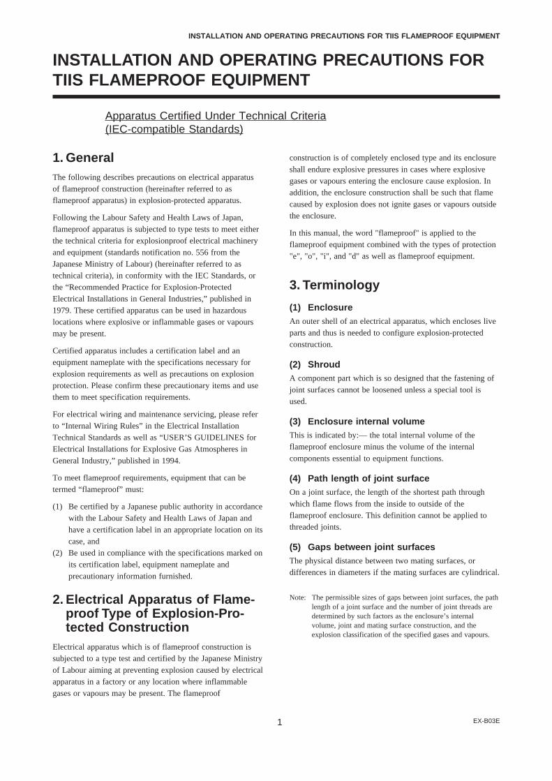
EX-B03E1
INSTALLATION AND OPERATING PRECAUTIONS FOR TIIS FLAMEPROOF EQUIPMENT
INSTALLATION AND OPERATING PRECAUTIONS FORTIIS FLAMEPROOF EQUIPMENT
Apparatus Certified Under Technical Criteria(IEC-compatible Standards)
1. GeneralThe following describes precautions on electrical apparatusof flameproof construction (hereinafter referred to asflameproof apparatus) in explosion-protected apparatus.
Following the Labour Safety and Health Laws of Japan,flameproof apparatus is subjected to type tests to meet eitherthe technical criteria for explosionproof electrical machineryand equipment (standards notification no. 556 from theJapanese Ministry of Labour) (hereinafter referred to astechnical criteria), in conformity with the IEC Standards, orthe “Recommended Practice for Explosion-ProtectedElectrical Installations in General Industries,” published in1979. These certified apparatus can be used in hazardouslocations where explosive or inflammable gases or vapoursmay be present.
Certified apparatus includes a certification label and anequipment nameplate with the specifications necessary forexplosion requirements as well as precautions on explosionprotection. Please confirm these precautionary items and usethem to meet specification requirements.
For electrical wiring and maintenance servicing, please referto “Internal Wiring Rules” in the Electrical InstallationTechnical Standards as well as “USER’S GUIDELINES forElectrical Installations for Explosive Gas Atmospheres inGeneral Industry,” published in 1994.
To meet flameproof requirements, equipment that can betermed “flameproof” must:
(1) Be certified by a Japanese public authority in accordancewith the Labour Safety and Health Laws of Japan andhave a certification label in an appropriate location on itscase, and
(2) Be used in compliance with the specifications marked onits certification label, equipment nameplate andprecautionary information furnished.
2. Electrical Apparatus of Flame-proof Type of Explosion-Pro-tected Construction
Electrical apparatus which is of flameproof construction issubjected to a type test and certified by the Japanese Ministryof Labour aiming at preventing explosion caused by electricalapparatus in a factory or any location where inflammablegases or vapours may be present. The flameproof
construction is of completely enclosed type and its enclosureshall endure explosive pressures in cases where explosivegases or vapours entering the enclosure cause explosion. Inaddition, the enclosure construction shall be such that flamecaused by explosion does not ignite gases or vapours outsidethe enclosure.
In this manual, the word "flameproof" is applied to theflameproof equipment combined with the types of protection"e", "o", "i", and "d" as well as flameproof equipment.
3. Terminology
(1) EnclosureAn outer shell of an electrical apparatus, which encloses liveparts and thus is needed to configure explosion-protectedconstruction.
(2) ShroudA component part which is so designed that the fastening ofjoint surfaces cannot be loosened unless a special tool isused.
(3) Enclosure internal volumeThis is indicated by:— the total internal volume of theflameproof enclosure minus the volume of the internalcomponents essential to equipment functions.
(4) Path length of joint surfaceOn a joint surface, the length of the shortest path throughwhich flame flows from the inside to outside of theflameproof enclosure. This definition cannot be applied tothreaded joints.
(5) Gaps between joint surfacesThe physical distance between two mating surfaces, ordifferences in diameters if the mating surfaces are cylindrical.
Note: The permissible sizes of gaps between joint surfaces, the pathlength of a joint surface and the number of joint threads aredetermined by such factors as the enclosure’s internalvolume, joint and mating surface construction, and theexplosion classification of the specified gases and vapours.

EX-B03E2
INSTALLATION AND OPERATING PRECAUTIONS FOR TIIS FLAMEPROOF EQUIPMENT
4. Installation of Flameproof Ap-paratus
(1) Installation AreaFlameproof apparatus may be installed, in accordance withapplicable gases, in a hazardous area in Zone 1 or 2, wherethe specified gases are present. Those apparatus shall not beinstalled in a hazardous area in Zone 0.
Note: Hazardous areas are classified in zones based upon thefrequency of the appearance and the duration of an explosivegas atmosphere as follows:Zone 0: An area in which an explosive gas atmosphere is
present continuously or is present for long periods.Zone 1: An area in which an explosive gas atmosphere is
likely to occur in normal operation.Zone 2: An area in which an explosive gas atmosphere is not
likely to occur in normal operation and if it doesoccur it will exist for a short period only.
(2) Environmental ConditionsThe standard environmental condition for the installation offlameproof apparatus is limited to an ambient temperaturerange from –20°C to +40°C (for products certified underTechnical Criteria). However, some field-mountedinstruments may be certified at an ambient temperature up to+60°C as indicated on the instrument nameplates. If theflameproof apparatus are exposed to direct sunshine orradiant heat from plant facilities, appropriate thermalprotection measures shall be taken.
5. External Wiring for FlameproofApparatus
Flameproof apparatus require cable wiring or flameproofmetal conduits for their electrical connections. For cablewiring, cable glands (cable entry devices for flameproof type)to wiring connections shall be attached. For metal conduits,attach sealing fittings as close to wiring connections aspossible and completely seal the apparatus. All non-livemetal parts such as the enclosure shall be securely grounded.For details, see the “USER’S GUIDELINES for ElectricalInstallations for Explosive Gas Atmospheres in GeneralIndustry,” published in 1994.
(1) Cable Wiring• For cable wiring, cable glands (cable entry devices for
flameproof type) specified or supplied with the apparatusshall be directly attached to the wiring connections tocomplete sealing of the apparatus.
• Screws that connect cable glands to the apparatus arethose for G-type parallel pipe threads (JIS B 0202) withno sealing property. To protect the apparatus fromcorrosive gases or moisture, apply nonhardening sealantsuch as liquid gaskets to those threads for waterproofing.
• Specific cables shall be used as recommended by the“USER’S GUIDELINES for Electrical Installations forExplosive Gas Atmospheres in General Industry,”published in 1994.
• In necessary, appropriate protective pipes (conduit orflexible pipes), ducts or trays shall be used forpreventing the cable run (outside the cable glands) fromdamage.
• To prevent explosive atmosphere from being propagatedform Zone 1 or 2 hazardous location to any differentlocation or non-hazardous location through the protectivepipe or duct, apply sealing of the protective pipes in thevicinity of individual boundaries, or fill the ducts withsand appropriately.
• When branch connections of cables, or cable connectionswith insulated cables inside the conduit pipes are made,a flameproof or increased-safety connection box shall beused. In this case, flameproof or increased-safety cableglands meeting the type of connection box must be usedfor cable connections to the box.
(2) Flameproof Metal Conduit Wiring• For the flameproof metal conduit wiring or insulated
wires shall be used as recommended by the USER’SGUIDELINES for Electrical Installations for ExplosiveGas Atmospheres in General Industry, published in1994.
• For conduit pipes, heavy-gauge steel conduitsconforming to JIS C 8305 Standard shall be used.
• Flameproof sealing fittings shall be used in the vicinityof the wiring connections, and those fittings shall befilled with sealing compounds to complete sealing of theapparatus. In addition, to prevent explosive gases,moisture, or flame caused by explosion form beingpropagated through the conduit, always provide sealingfittings to complete sealing of the conduit in thefollowing locations:
(a) In the boundaries between the hazardous and non-hazardous locations.
(b) In the boundaries where there is a differentclassification of hazardous location.
• For the connections of the apparatus with a conduit pipeor its associated accessories, G-type parallel pipe threads(JIS B 0202) shall be used to provide a minimum offive-thread engagement to complete tightness. Inaddition, since these parallel threads do not have sealingproperty, nonhardening sealant such as liquid gasketsshall thus be applied to those threads for ensuringwaterproofness.
• If metal conduits need flexibility, use flameproof flexiblefittings.

EX-B03E3
INSTALLATION AND OPERATING PRECAUTIONS FOR TIIS FLAMEPROOF EQUIPMENT
6. Maintenance of FlameproofApparatus
To maintain the flameproof apparatus, do the following. (Fordetails, see Chapter 10 “MAINTENANCE OF EXPLOSION-PROTECTED ELECTRICAL INSTALLATION” in theUSER’S GUIDELINES for Electrical Installations forExplosive Gas Atmospheres in General Industry.)
(1) Maintenance servicing with the power on.Flameproof apparatus shall not be maintenance-serviced withits power turned on. However, in cases where maintenanceservicing is to be conducted with the power turned on, withthe equipment cover removed, always use a gas detector tocheck that there is no explosive gas in that location. If itcannot be checked whether an explosive gas is present or not,maintenance servicing shall be limited to the following twoitems:
(a) Visual inspectionVisually inspect the flameproof apparatus, metalconduits, and cables for damage or corrosion, and othermechanical and structural defects.
(b) Zero and span adjustmentsThese adjustments should be made only to the extentthat they can be conducted from the outside withoutopening the equipment cover. In doing this, great caremust be taken not to cause mechanical sparks with tools.
(2) RepairIf the flameproof apparatus requires repair, turn off the powerand transport it to a safety (non-hazardous) location. Observethe following points before attempting to repair theapparatus.
(a) Make only such electrical and mechanical repairs as willrestore the apparatus to its original condition. For theflameproof apparatus, the gaps and path lengths of jointsand mating surfaces, and mechanical strength ofenclosures are critical factors in explosion protection.Exercise great care not to damage the joints or shock theenclosure.
(b) If any damage occurs in threads, joints or matingsurfaces, inspection windows, connections between thetransmitter and terminal box, shrouds or clamps, orexternal wiring connections which are essential inflameproofness, contact Yokogawa Electric Corporation.
CAUTION
Do not attempt to re-process threaded connections orrefinish joints or mating surfaces.
(c) Unless otherwise specified, the electrical circuitry andinternal mechanisms may be repaired by componentreplacement, as this will not directly affect the
requirements for flameproof apparatus (however, bear inmind that the apparatus must always be restored to itsoriginal condition). If you attempt to repair theflameproof apparatus, company-specified componentsshall be used.
(d) Before starting to service the apparatus, be sure to checkall parts necessary for retaining the requirements forflameproof apparatus. For this, check that all screws,bolts, nuts, and threaded connections have properly beentightened.
(3) Prohibition of specification changes andmodifications
Do not attempt to change specifications or make modifica-tions involving addition of or changes in external wiringconnections.
7. Selection of Cable Entry De-vices for Flameproof Type
IMPORTANT
The cable glands (cable entry devices for flameprooftype) conforming to IEC Standards are certified incombination with the flameproof apparatus. So,Yokogawa-specified cable entry devices for flameprooftype shall be used to meet this demand.
References:(1) Type Certificate Guide for Explosion-Protected Con-
struction Electrical Machinery and Equipment (relatingto Technical Standards Conforming to InternationalStandards), issued by the Technical Institution ofIndustrial Safety, Japan
(2) USER’S GUIDELINES for Electrical Installations forExplosive Gas Atmospheres in General Industry (1994),issued by the Japanese Ministry of Labour, the ResearchInstitute of Industrial Safet
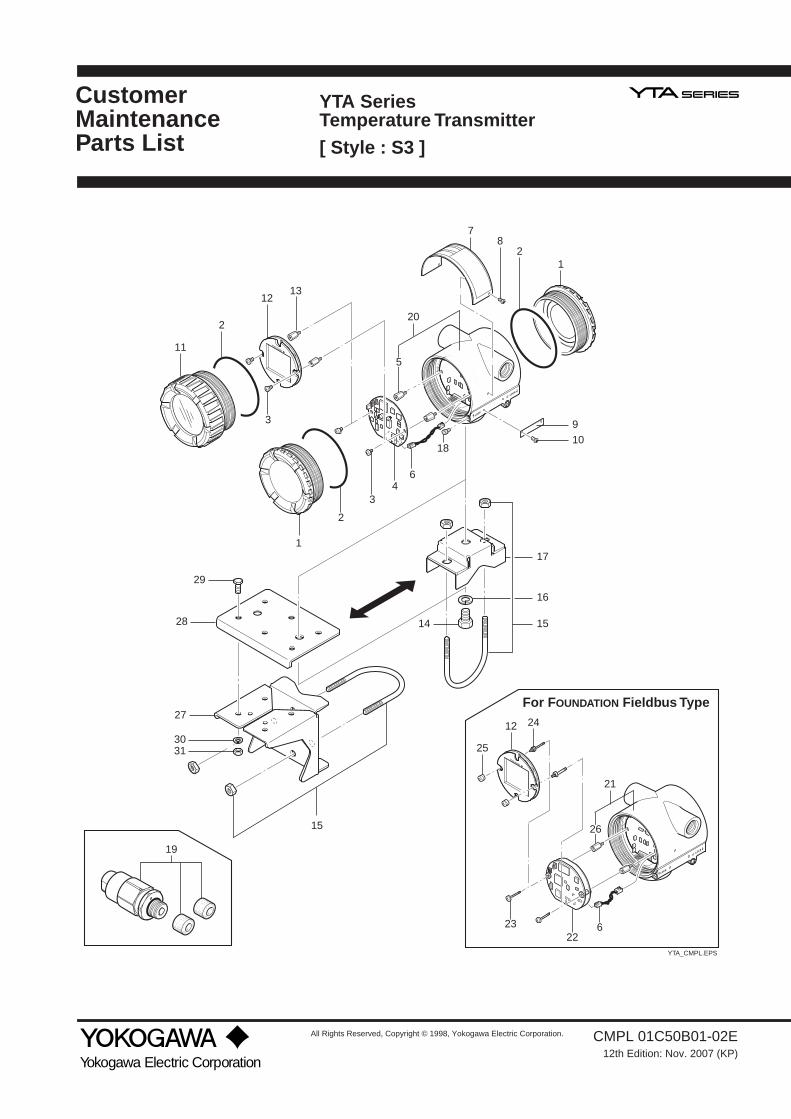
CustomerMaintenanceParts List
All Rights Reserved, Copyright © 1998, Yokogawa Electric Corporation.
Yokogawa Electric Corporation
CMPL 01C50B01-02E12th Edition: Nov. 2007 (KP)
11
7
1
82
2
3
1
15
2
34
6
9
1213
20
10
14
29
28
27
3031
17
16
15
YTA_CMPL.EPS
18
19
23
12
25
24
226
For FOUNDATION Fieldbus Type
5
21
26
YTA SeriesTemperature Transmitter[ Style : S3 ]

2
CMPL 01C50B01-02ENov. 2007Subject to change without notice. Printed in Japan.
CoverO-RingScrew MachineCPU Assembly for BRAIN or HART Communication type Stud Bolt
Connector AssemblyName PlateScrewTag PlateScrew
Cover AssemblyLCD AssemblyStud BoltBolt HexagonU-bolt Assembly
Washer SpringBracketScrew (for CENELEC, SAA and TIIS flameproof type)Cable Grand Assembly (for JIS Flameproof; option code: /JF3) For Electrical Connection: G 1/2 female (option code: /G11)
Case Assembly for BRAIN or HART Communication typeCase Assembly for Fieldbus Communication typeCPU Assembly for Fieldbus Communication typeScrew MachineScrew
NutStud BoltBracketBracketScrew
WasherNut
12345
6789
10
1112131415
16171819
2021222324
2526272829
3031
F9165EAB1000ERY9406JBSee Table 1B1002BT
F9342MW—
F9300AGF9165DFF9300AG
F9165FAF9167DAB1001BTY9016NUD0117XL-A
Y9100SUF9165CYY9406ZU
BelowG9601AM
— ——
Y9420JBF9165KA
F9165KFF9165KDF9284NZF9165QBY9616NU
Y9600SUY9601BU
22212
11212
11211
1121
11122
22114
44
Item Part No. DescriptionQty
With/CM1
F9167BUF9167BWF9167BVF9167BX
Model Communicationprotocol
Without /CM1
-D (BRAIN)-E (HART)-D (BRAIN)-E (HART)-D (BRAIN)-E (HART)
F9167BJF9167BMF9167BKF9167BNF9167BLF9167BP
Table 1. CPU Assembly (for BRAIN and HART)
YTA110
YTA310
YTA320
Input sensor type Pt100 three-wire systemCalibration range lower limitCalibration range upper limit
Calibration unitSensor burnout
“0”“100”“°C”
High (110%, 21.6mA DC)
Table 2. Setting upon shipment
CPU Assembly is shipped with the setting shown in Table 2.

IM 01C50B01-01E
REVISION RECORDTitle: Model YTA series Temperature Transmitter (Hardware) [Style: S3]Manual No.: IM 01C50B01-01E
Edition Date Page Revised item
1st Sep. 1998 — New Publication
2nd Nov. 1998 2.7.1 Add subsection 2.7.1 CSA certification.2.7.2 Add subsection 2.7.2 CENELEC(KEMA) certificated.2.8 Add subsection 2.8 EMC Conformity Standards.5.5 Add wiring cautions for intrinsically safe type and flameproof type.7.1 Correct errors.
2-52-72-95-5
7-2 to 7-3
3rd Jan. 1999 2.7.3 Add subsection 2.7.3 FM certification.5.4 Delete resistance 4-wire type. (Figure 5.6 &5.7)6.2.2 Delete resistance 4-wire type. (Figure 6.1)6.4. Add HART parameter.6.5 Correct errors. (Er-05 & Er-06 in Table 6.4)7.1 Delete resistance 4-wire type7.3 Add optional code /FF1.7.4 Add Terminal dimensions.CMPL 1C50B1-02E 1st to 2ndPage 1 Correct dimensions
2-95-36-26-76-97-17-57-6
CMPL
4th June 1999 Add Ex-B02E 'Installation and Operating Precautions for JIS Flameproof Equipment'.2.1 Add C-tick mark.2.7.2 Add IEC (KEMA) Type of protection 'n'2.7.3 Add FM Intrinsically Safe Type2.7.4 Add JIS Flameproof Type2.8 Add C-tick mark5.1 Add 'IMPORTANT' for JIS Flameproof type.5.3.2 Add 'WARNING' for JIS Flameproof type.5.5(2) Add cable wiring procedure using Flameproof Packing adapter.6.3 Add Figure 6.3.7.3 Add optional code /CM1, /FU1, /JF3, /G11, and /G12. Add Ex-B02E 'Installation and Operating Precautions for JIS Flameproof Equipment'. Add item 18, 19, 20, and 21.
Contents
2-12-7
2-102-122-135-15-35-66-37-4
Ex-B02E
CMPL
5th July 2000
Add Style code Add 2.7.5 Add '2.7.5 SAA Certification' 7.1 Correct Description of Ambient temperature effect Add Table 7.2 YTA110 Effect of Ambient Temperature' 7.4 Add Stainless steel housing Change Item 4
CoverContents
2-137-17-37-4
CMPL
6th July 2000
2-15 Change referred standard 7. Add Notes for Fieldbus type, change EMC standard.7.1 Add codes and notes for Fieldbus type. EX-B02E superseded to EX-B03E. CMPL 4th to 5th edition (Adding Fieldbus related parts)
2-157-1
7-4 to 7-6 EX-B03E
CMPL
7th July 2001
Add “ For Safety Using.”2.7.2 Add descriptions based on ATEX directive.7.3 Add Optional code KU2.CMPL 6th to 7th edition (Fieldbus Type Part No. correction) 1. Item 5, B1002BT to Item 26, F9165KD 2. Item 23, F9165KA (Screw) to Y9420JB (Screw machine) 3. Item 24, Y9420JB (Screw machine) to F9165KA (Screw)CMPL 1C50B1-02E 7th to CMPL 01C50B01-02E 8th
1-12-57-6
CMPL
8th May 2002
Rev.1.EPS

IM 01C50B01-01E
Edition Date Page Revised item
9th Apr. 2003 Add Vertical pipe mounting bracket. Add Vertical pipe mounting bracket.7.2 Add mounting bracket code D.7.4 Change Dimensions.CMPL 01C50B01-02E 8th to 9th Add Part No. Item Part No. 27 F9284NZ 28 F9165QB 29 F9616NU 30 Y9600SU 31 Y9601BU
2-14-17-57-7
CMPL
10th Dec. 2004 Change Title of Flameproof (JIS → TIIS) Add ‘ATEX Documentation.’1. Add Attention on Maintenance.1. Add ATEX Documentation.2.7.2 Correct errors.3.1 Add Notes for Lock screw.6.3 Add Description about SAA to CAUTION.7.3 Add C2, C3 Options.CMPL 9th to 10th edition. Delete Part Number of Name Plate. Add Note for Lock screw. Add Ports Number of CPU Assembly for /KS25.
—Contents
1-21-32-63-16-27-5
CMPL
11th Sep. 2006 Change Style Code Add 2.9 Low Voltage Directive
2. Add Certificate Number and Applicable Standard for Explosion Protected Types.
2.9 Add 2.9 Low Voltage Directive.6.5 Add Error code.7.1 Add Stability Specifications.7.1 Add Note for YTA110 Ambient Temperature Effect.7.3 Add Optional Code CA.7.3 Add Certificate Number and Applicable Standard for Explosion Protected Types.
CoverContents2-3, 2-42-5, 2-62-8, 2-92-10
2-116-67-17-37-5
7-6, 7-7
12th Nov. 2007 2.7.2 Change Applicable standards and add Dust Ignition Proof for KU2.2.7.6 Add IECEx Certification.7.3 Add Option PR.CMPL Add setting upon shipment for CPU Assembly.
2-6, 7-62-11, 7-7
7-5CMPL
Rev.2.EPS