User's Manual - Wabash College: Wabash College:...
87
User's Manual MOD. SY 1527 26 August 2002 Revision n. 4 UNIVERSAL MULTICHANNEL POWER SUPPLY SYSTEM USER’S MANUAL NPO: 00103/97:1527y.MUTx/04
Transcript of User's Manual - Wabash College: Wabash College:...
User's
Manual
MOD. SY 1527
26 August 2002 Revision n. 4
UNIVERSAL MULTICHANNEL POWER SUPPLY SYSTEM
USER’S MANUAL
NPO: 00103/97:1527y.MUTx/04

Document type: Title: Revision date: Revision: User's Manual (MUT) Mod. SY1527, universal multichannel power supply system 26/08/2002 4
NPO: Filename: Number of pages: Page: 00103/97:1527y.MUTx/04 SY1527USERMANUAL_REV4.DOC 86 2
TABLE OF CONTENTS
1. ABOUT THIS MANUAL........................................................................................................................... 7
1.1 ORGANISATION ...................................................................................................................................... 8 1.2 CONVENTIONS........................................................................................................................................ 9
1.2.1 Safety rules .................................................................................................................................... 9 1.2.2 Electrical signal specifications ..................................................................................................... 9
2. GENERAL DESCRIPTION OF THE SYSTEM ................................................................................... 10
2.1 OVERVIEW ........................................................................................................................................... 10 2.2 SHORT FUNCTIONAL DESCRIPTION ....................................................................................................... 13 2.3 TECHNICAL SPECIFICATION TABLES...................................................................................................... 16
3. SAFETY INFORMATION AND OPERATION REQUIREMENTS .................................................. 19
3.1 GENERAL INFORMATION....................................................................................................................... 19 3.1.1 Injury Precautions....................................................................................................................... 19 3.1.2 Product Damage Precautions ..................................................................................................... 20 3.1.3 EC Certifications and Compliance.............................................................................................. 20 3.1.4 Terms in this Manual................................................................................................................... 20
3.2 SAFETY TERMS AND SYMBOLS ON THE PRODUCT................................................................................ 20 3.3 GENERAL OPERATION REQUIREMENTS ................................................................................................ 21
4. SYSTEM AND CHANNEL CONTROL................................................................................................. 22
4.1 INTRODUCTION .................................................................................................................................... 22 4.2 SYSTEM CONTROL................................................................................................................................ 22
4.2.1 NIM / TTL standard selection ..................................................................................................... 23 4.2.2 LOCAL/REMOTE Power-On ...................................................................................................... 23 4.2.3 LOCAL/REMOTE Channel Enable............................................................................................. 23 4.2.4 VSEL command ........................................................................................................................... 24 4.2.5 ISEL command ............................................................................................................................ 24 4.2.6 KILL command............................................................................................................................ 24 4.2.7 RESET command......................................................................................................................... 24 4.2.8 INTERLOCK command............................................................................................................... 25 4.2.9 HV SYNC..................................................................................................................................... 26
4.3 SYSTEM STATUS MONITORING.............................................................................................................. 26 4.3.1 Over Current ............................................................................................................................... 26 4.3.2 Under Voltage ............................................................................................................................. 27 4.3.3 Over Voltage ............................................................................................................................... 27 4.3.4 Trip.............................................................................................................................................. 27 4.3.5 Reset flag..................................................................................................................................... 27 4.3.6 Check passed............................................................................................................................... 27 4.3.7 GEN............................................................................................................................................. 28 4.3.8 CH-ON ........................................................................................................................................ 28 4.3.9 Over Temperature ....................................................................................................................... 28 4.3.10 Fan Failure ................................................................................................................................. 28
Document type: Title: Revision date: Revision: User's Manual (MUT) Mod. SY1527, universal multichannel power supply system 26/08/2002 4
NPO: Filename: Number of pages: Page: 00103/97:1527y.MUTx/04 SY1527USERMANUAL_REV4.DOC 86 3
4.3.11 Pwr Failure................................................................................................................................. 28 4.4 CHANNEL PARAMETERS....................................................................................................................... 29
4.4.1 CHANNEL NUMBER (CH #) ..................................................................................................... 29 4.4.2 CHANNEL NAME (CHANNEL) ................................................................................................ 30 4.4.3 VMAX HARDWARE (HVMAX) ................................................................................................. 30 4.4.4 VMAX SOFTWARE (SVMAX) ................................................................................................... 30 4.4.5 V0SET ......................................................................................................................................... 30 4.4.6 I0SET .......................................................................................................................................... 30 4.4.7 V1SET ......................................................................................................................................... 31 4.4.8 I1SET .......................................................................................................................................... 31 4.4.9 RAMP-UP (RUp) ........................................................................................................................ 31 4.4.10 RAMP-DOWN (RDwn) ............................................................................................................... 31 4.4.11 VMON ......................................................................................................................................... 31 4.4.12 IMON .......................................................................................................................................... 31 4.4.13 TRIP............................................................................................................................................ 32 4.4.14 POWER (PW) ............................................................................................................................. 32 4.4.15 POWER-ON (POn) ..................................................................................................................... 33 4.4.16 POWER-DOWN (PDwn)............................................................................................................. 33
4.5 CHANNEL STATUS ................................................................................................................................ 33 4.6 BOARD STATUS .................................................................................................................................... 33
5. SYSTEM POWER-ON............................................................................................................................. 35
5.1 PRELIMINARY CHECK........................................................................................................................... 35 5.2 LOCAL POWER-ON............................................................................................................................... 35 5.3 REMOTE POWER-ON............................................................................................................................ 36
6. CONFIGURING THE INTERFACES ................................................................................................... 37
6.1 RS232 INTERFACE ............................................................................................................................... 37 6.2 ETHERNET INTERFACE (TCP/IP PROTOCOL) ........................................................................................ 38
6.2.1 Configuring the SY 1527 System for network connection ........................................................... 38 6.2.2 Configuring the host PC ............................................................................................................. 38 6.2.3 Verifying connection ................................................................................................................... 39
6.3 H.S. CAENET INTERFACE .................................................................................................................. 40
7. OPERATING MODES............................................................................................................................. 41
7.1 STANDALONE OPERATION .................................................................................................................... 41 7.1.1 Local Control Devices ................................................................................................................ 42 7.1.2 Software Version......................................................................................................................... 43 7.1.3 Menu Structure............................................................................................................................ 44 7.1.4 Welcome Window........................................................................................................................ 45 7.1.5 Login Window ............................................................................................................................. 45 7.1.6 Start Up Window......................................................................................................................... 46 7.1.7 The - Menu: About ..................................................................................................................... 48
7.1.8 The - Menu: Session................................................................................................................. 49 7.1.9 The MAIN Menu: Channels ........................................................................................................ 50 7.1.10 The MAIN Menu: Crate Map ...................................................................................................... 55 7.1.11 The MAIN Menu: Connect .......................................................................................................... 56 7.1.12 The MAIN Menu: Logout ............................................................................................................ 56 7.1.13 The GROUPS Menu and relevant commands............................................................................. 56

Document type: Title: Revision date: Revision: User's Manual (MUT) Mod. SY1527, universal multichannel power supply system 26/08/2002 4
NPO: Filename: Number of pages: Page: 00103/97:1527y.MUTx/04 SY1527USERMANUAL_REV4.DOC 86 4
7.1.14 The VIEW Menu and relevant commands ................................................................................... 59 7.1.15 The UTILITY Menu: Kill ............................................................................................................. 59 7.1.16 The UTILITY Menu: Clear Alarm ............................................................................................... 60 7.1.17 The UTILITY Menu: Status ......................................................................................................... 61 7.1.18 The UTILITY Menu: Trip Handling ............................................................................................ 62 7.1.19 The UTILITY Menu: Format ....................................................................................................... 62 7.1.20 The UTILITY Menu: Board Upgrade.......................................................................................... 63 7.1.21 The UTILITY Menu: System Upgrade......................................................................................... 66 7.1.22 The SETUP Menu: Reset Flag .................................................................................................... 67 7.1.23 The SETUP Menu: Communications .......................................................................................... 69 7.1.24 The SETUP Menu: Security ........................................................................................................ 69 7.1.25 The SETUP Menu: Log Options.................................................................................................. 69 7.1.26 The SETUP Menu: Tech Info ...................................................................................................... 70 7.1.27 The SETUP Menu: HV Clock Conf. ............................................................................................ 70
7.2 REMOTE OPERATION VIA TERMINAL .................................................................................................... 72 7.2.1 Using the RS232 interface........................................................................................................... 73 7.2.2 Using the H.S. CAENET (Multicrate Operation) ........................................................................ 73 7.2.3 Using the TCP/IP protocol via Ethernet (Telnet Client) ............................................................. 75
7.3 REMOTE OPERATION VIA HOST COMPUTER.......................................................................................... 76
8. TRIP HANDLING .................................................................................................................................... 78
8.1 INTERNAL TRIP .................................................................................................................................... 78 8.2 EXTERNAL TRIP ................................................................................................................................... 79
9. ERROR HANDLING ............................................................................................................................... 80
10. SECURE ACCESS AND USER’S PROFILE MANAGEMENT...................................................... 81
10.1 MULTILEVEL LOGIN PROFILE ENVIRONMENT ........................................................................................ 81 10.1.1 Guest profile................................................................................................................................ 84 10.1.2 User profile ................................................................................................................................. 84 10.1.3 Administrator profile................................................................................................................... 84
10.2 GENERAL SETTINGS FOR PASSWORD PROTECTION ................................................................................ 84 10.3 ASSIGNING A LOGIN PROFILE ................................................................................................................ 84 10.4 CUSTOMISING THE ENVIRONMENT........................................................................................................ 84
11. SYSTEM DIAGNOSTIC PROCEDURES.......................................................................................... 85
APPENDIX A .................................................................................................................................................... 86
SY1527 SYSTEM FRONT PANEL....................................................................................................................... 87

Document type: Title: Revision date: Revision: User's Manual (MUT) Mod. SY1527, universal multichannel power supply system 26/08/2002 4
NPO: Filename: Number of pages: Page: 00103/97:1527y.MUTx/04 SY1527USERMANUAL_REV4.DOC 86 5
LIST OF FIGURES
FIG. 2.1 – LAYOUT OF THE MAIN MECHANICAL SECTIONS OF THE SY1527 MAINFRAME ...................................... 10 FIG. 2.2 – BLOCK DIAGRAM OF THE FUNCTIONAL PARTS OF THE SY1527 SYSTEM............................................... 15 FIG. 4.1 – RESET TIMING ................................................................................................................................... 25 FIG. 4.2 – COMPLETE CHANNEL ADDRESS ........................................................................................................... 29 FIG. 6.1 – RS232 CONNECTOR PIN ASSIGNMENT.................................................................................................. 37 FIG. 6.2 - THE RESULT OF A SUCCESSFUL "PING" TO THE SY 1527 SYSTEM........................................................ 39 FIG. 7.1 – STANDALONE OPERATION ................................................................................................................... 41 FIG. 7.2 – MENU STRUCTURE IN STANDALONE OPERATION ................................................................................. 44 FIG. 7.3 – WELCOME SCREEN IN STANDALONE OPERATION................................................................................ 45 FIG. 7.4 – LOGIN WINDOW .................................................................................................................................. 46 FIG. 7.5 – START UP WINDOW............................................................................................................................. 47 FIG. 7.6 – ABOUT WINDOW................................................................................................................................. 48 FIG. 7.7 – SESSION WINDOW ............................................................................................................................... 49 FIG. 7.8 – CHANNELS WINDOW ........................................................................................................................... 50 FIG. 7.9 – CRATE MAP WINDOW ......................................................................................................................... 55 FIG.7.10 – CONNECT WINDOW............................................................................................................................ 56 FIG. 7.11 – ADD CHANNELS POP-UP WINDOW..................................................................................................... 57 FIG. 7.12 – REMOVE CHANNELS POP-UP WINDOW .............................................................................................. 58 FIG. 7.13 – GROUP MODE WINDOW..................................................................................................................... 59 FIG. 7.14 – KILL POP-UP WINDOW....................................................................................................................... 60 FIG. 7.15 – CLEAR ALARM POP-UP WINDOW....................................................................................................... 61 FIG. 7.16 – STATUS POP-UP WINDOW .................................................................................................................. 62 FIG. 7.17 – FORMAT POP-UP WINDOW................................................................................................................. 63 FIG. 7.18 – BOARD UPGRADE POP-UP WINDOW................................................................................................... 65 FIG. 7.19 – SYSTEM UPGRADE POP-UP WINDOW ................................................................................................. 67 FIG. 7.20 – RESET FLAG POP-UP WINDOW........................................................................................................... 68 FIG. 7.21 – TECH INFO POP-UP WINDOW ............................................................................................................. 70 FIG. 7.22 – REMOTE OPERATION VIA TERMINAL ................................................................................................. 72 FIG. 7.23 – WELCOME SCREEN IN TERMINAL OPERATION................................................................................... 73 FIG. 7.24 – REMOTE OPERATION VIA HOST COMPUTER ...................................................................................... 76 FIG. 7.25 – SOFTWARE ARCHITECTURE................................................................................................................ 77 FIG. 8.1 – TRIP BUS SCHEME ............................................................................................................................... 79
Document type: Title: Revision date: Revision: User's Manual (MUT) Mod. SY1527, universal multichannel power supply system 26/08/2002 4
NPO: Filename: Number of pages: Page: 00103/97:1527y.MUTx/04 SY1527USERMANUAL_REV4.DOC 86 6
LIST OF TABLES
TABLE 2.1 - TECHNICAL SPECIFICATIONS OF THE SY1527 MAINFRAME: GENERAL .............................................. 16 TABLE 2.2 - TECHNICAL SPECIFICATIONS OF THE SY1527 MAINFRAME: FRONT AND REAR PANEL COMPONENTS 17 TABLE 2.3 - TECHNICAL SPECIFICATIONS OF THE SY1527 MAINFRAME: INPUT AND OUTPUT SIGNALS................. 17 TABLE 6.1 – RS232 PORT DEFAULT SETTINGS.................................................................................................... 37 TABLE 6.2 – TCP/IP PROTOCOL DEFAULT SETTINGS .......................................................................................... 38 TABLE 6.3 – AN EXAMPLE OF TCP/IP PROTOCOL SETTINGS............................................................................... 38 TABLE 6.4 – H.S. CAENET DEFAULT SETTINGS ................................................................................................ 40 TABLE 7.1 – LOCAL CONTROL COMMANDS AND EXTERNAL KEYBOARD COMMANDS........................................... 43 TABLE 10.1 – OPERATIONS ALLOWED IN A GUEST, USER AND ADMINISTRATOR LOGIN SESSION ......................... 83
Document type: Title: Revision date: Revision: User's Manual (MUT) Mod. SY1527, universal multichannel power supply system 26/08/2002 4
NPO: Filename: Number of pages: Page: 00103/97:1527y.MUTx/04 SY1527USERMANUAL_REV4.DOC 86 7
1. About this manual The purpose of this guide is to illustrate:
• the several parameters and commands available for the control and status monitoring of the SY1527 Universal Multichannel Power Supply System and of the board channels,
• the requirements and instructions for its correct operation in different hardware configurations,
• the User Software Interface used to control the system interactively. The preliminary section of the guide starts with a short description of the SY1527 system with a summary of its main features and performances. The core of the guide consists of two sections: a reference section with a detailed description of the commands, alarms and parameters which allow for the control and monitoring of the system and of the board channels; a second section which illustrates the operating modes of the SY1527 system for different hardware configurations for interactive control of the system, paying particular attention to the User Software Interface for Standalone and Terminal operation and to that for Remote operation via WEB Browser. A detailed description of all hardware components and system installation instructions can be found in the Hardware Installation Guide.
Document type: Title: Revision date: Revision: User's Manual (MUT) Mod. SY1527, universal multichannel power supply system 26/08/2002 4
NPO: Filename: Number of pages: Page: 00103/97:1527y.MUTx/04 SY1527USERMANUAL_REV4.DOC 86 8
1.1 Organisation This guide is organised as follows:
Chapter 1 – About this manual: it shortly describes the objectives and organisation of this guide;
Chapter 2 – General description of the system: it contains an overview of the system and its main features, a very short functional description and some reference tables with a summary of the system technical specifications;
Chapter 3 – Safety information and operation requirements: it contains general safety rules and the requirements for a correct system operation;
Chapter 4 – System and channel control: this reference section contains the description of all commands, parameters and alarms to control and monitor the status of the system and of the board channels;
Chapter 5 – System Power-On: it contains the procedure for the power-on of the system together with a first check of its correct operation;
Chapter 6 – Configuring the interfaces: it contains the procedure for the correct software configuration of the interfaces for the system remote control;
Chapter 7 – Operating modes: this is the guide core which contains the instructions to operate the system in different hardware configurations: in particular, the User Software Interface used in standalone operation and in remote operation via terminal and that used in remote operation via Web Browser are fully described;
Chapter 8 – Trip handling: it contains further details about how to handle trip conditions;
Chapter 9 – Error handling: it contains further details about how to handle error conditions;
Chapter 10 – Secure access and user’s profile management: this section has been conceived for system administrators in order to allow for secure management of the system.
Chapter 11 – System diagnostic procedures: a reference section containing some diagnostic procedures to test system correct operation;
Appendix A – Front Panel of the SY1527 system: a useful reference figure of the SY1527 Front Panel, including the Primary Power Supply and the Power Supply Units.

Document type: Title: Revision date: Revision: User's Manual (MUT) Mod. SY1527, universal multichannel power supply system 26/08/2002 4
NPO: Filename: Number of pages: Page: 00103/97:1527y.MUTx/04 SY1527USERMANUAL_REV4.DOC 86 9
1.2 Conventions The conventions adopted all through the manual are shortly listed in the following.
1.2.1 Safety rules The user is requested to pay particular attention to the parts of the document containing the following terms: WARNING: Warning statements identify conditions or practices that could result in injury or loss of life. CAUTION: Caution statements identify conditions or practices that could result in damage to this product or other property. Please pay particular attention to the grey areas where warning and caution statements are emphasised, as shown in the following examples:
CAUTION PLEASE NOTE THAT THE BOTTOM, TOP AND SIDE GRIDS OF THE FAN TRAY
UNIT MUST NOT BE COVERED UNDER ANY CIRCUMSTANCES!
WARNING DO NOT OPERATE WITHOUT COVERS!
1.2.2 Electrical signal specifications The polarity of the electrical signals can be chosen via software by the user. As a consequence, in this guide it has been adopted the following convention: TRUE: an electrical signal is indicated as TRUE when it is active. FALSE: an electrical signal is indicated as FALSE when it is not active.

Document type: Title: Revision date: Revision: User's Manual (MUT) Mod. SY1527, universal multichannel power supply system 26/08/2002 4
NPO: Filename: Number of pages: Page: 00103/97:1527y.MUTx/04 SY1527USERMANUAL_REV4.DOC 86 10
2. General description of the system This preliminary section contains a short description of the SY1527 system with a summary of its features and some tables with its main technical specifications. A detailed description of technical specifications and hardware installation instructions can be found in the Hardware Installation Guide.
2.1 Overview The SY1527 system is the fully equipped experiment version of a new line of power supply systems which represent CAEN's latest proposal in the matter of High Voltage and Low Voltage Power Supplying. This system outlines a completely new approach to power generation and distribution by allowing the housing, in the same mainframe, of a wide range of boards with different functions, such as High/Low Voltage boards, generic I/O boards (temperature, pressure monitors, etc.) and branch controllers, where the latter are used to control other remote generators and distributors. Modularity, flexibility and reliability are the key-points of its design, enabling this module to meet the requirements needed in a wide range of experimental conditions. The latter range from those of LHC experiments, in which the features of this model find prior application, to those of other less challenging, but still demanding, High Energy Physics experiments. The mainframe is housed in a 19"-wide, 8U-high euro-mechanics rack and hosts four main sections (refer to Fig. 2.1):
- the Board Section, with 16 slots to house boards, distributors and branch controllers;
- the Fan Tray Section, housing 6 fans disposed on two rows;
- the Power Supply Section, which consists of the primary power supply and up to 3 power supply units;
- the CPU and Front Panel Section which includes all interface facilities.
Board Section
Fan Unit1 2 341 5 67 8 9. 0 -CMD DELACK
CPU &Front Panel
Section
Power SupplySection
Power Supply Units Primary Power Supply
Fig. 2.1 – Layout of the main mechanical sections of the SY1527 mainframe
Document type: Title: Revision date: Revision: User's Manual (MUT) Mod. SY1527, universal multichannel power supply system 26/08/2002 4
NPO: Filename: Number of pages: Page: 00103/97:1527y.MUTx/04 SY1527USERMANUAL_REV4.DOC 86 11
The User Software Interface features the usual friendliness of the previous CAEN systems which now also includes a 7.7" colour LCD. A wide choice of interface facilities provides full communication compatibility with the previous systems and the feasibility of controlling heterogeneous external devices. Modularity has been one of the leading criteria in the design and development of the system: both the Power Supply Section and the Board Section are completely modular. The Power Supply Section allows different configurations with up to 3 power supply units per mainframe (up to 2250 W), while the Board Section can house up to 16 boards able to fulfil different functions. A new line of boards and distributors, analogous with those available for the SY527 system, and a set of branch controllers has been specially developed for this new system. The minimum system configuration consists of the primary power supply, one Power Supply Unit and one board. The concept of modularity has been extended up to the possibility of arranging ‘clusters’ constituted by one ‘intelligent’ SY1527 system able to drive other ‘non-intelligent’ systems, i.e. systems without CPU (to be implemented). The connections among the systems constituting the cluster are realised through a new CAEN interface, the Local Net. The extreme flexibility of the system, which allows to house indifferently, inside the same mainframe, boards with different functions, is further enhanced by the possibility of developing ad-hoc boards and even complete custom peripheral systems, including their hardware. The latter, actually, can be designed specifically for the installation onto the detectors used in the experiment. All the custom electronics can be anyway controlled by single boards which are inserted in the SY1527 mainframe and act as branch controllers. Fast, accurate set-up and monitoring of up to 1024 parameters (14-bit resolution on Voltages and Currents with standard boards) is available for each branch controller thanks to the use of one microprocessor per slot. All the operational parameters are stored in a non-volatile memory (EEPROM) to be still available after Power-Off. The parameters can be controlled either via CAEN traditional built-in links (RS232, H.S. CAENET) or via CERN-approved Fieldbuses or via Ethernet (TCP/IP). Programmable handling of parameters and errors is available as well. Channel trip control on other crates is performed via four external differential trip lines. A sophisticated trip handling via software allows to control and correlate trip conditions on the channels of the crate as well as of other crates connected to it. Live insertion and extraction of the boards, which reduces the down time of the global system, and easy access to the computing core and peripherals of the system completes the system flexibility. Easy interfacing is another key-point of the SY1527 system. Thanks to the H.S. CAENET interface, the system ensures full communication compatibility with the previous models. Besides the RS232 and Ethernet (TCP/IP) interfaces provided with the standard version of the system, CAN-bus can be furnished on request, as well as special boards featuring optical links for remote communications. Enhanced software programming features a unified command set independent from the interface used to communicate with the system. The Power Supply Section and Board Section can be externally synchronised via front panel connectors. Secure access to the system via Intranet is foreseen together with a multilevel management of custom user's profiles. In particular, three different access levels have been implemented: Guest, User and Administrator, each of which with password protection.
Document type: Title: Revision date: Revision: User's Manual (MUT) Mod. SY1527, universal multichannel power supply system 26/08/2002 4
NPO: Filename: Number of pages: Page: 00103/97:1527y.MUTx/04 SY1527USERMANUAL_REV4.DOC 86 12
Handy maintenance and upgrading, which constitute a major issue in the reliability of a system, are further guaranteed by the possibility of accessing and servicing the system via network facilities. Actually, Telnet and WWW access facilities allow remote debugging and technical support of the system, including future firmware upgrading.

Document type: Title: Revision date: Revision: User's Manual (MUT) Mod. SY1527, universal multichannel power supply system 26/08/2002 4
NPO: Filename: Number of pages: Page: 00103/97:1527y.MUTx/04 SY1527USERMANUAL_REV4.DOC 86 13
2.2 Short Functional description A block diagram of the SY1527 system is shown in Fig. 2.2, p.15. A single crate can host up to 16 Channel Boards, which can be chosen in a wide range of plug-in boards, from standard HV/LV boards and floating boards to generic I/O boards monitoring external parameters or branch controllers. All the types of boards can be freely mixed in the same crate so as to fit the user's needs. Both the Power-On and the Channel Out Enable of the System can be performed either locally or remotely. Remote Enable is performed by sending the proper input signal via the relevant front panel connector. Each crate may be controlled either locally or remotely. Local control is performed manually through a key-pad, a compact switch and a 7.7" colour LCD located on the front panel. Remote control is feasible via the interface connectors located on the front panel. These include a RS232 interface, which can be used to plug in a video terminal (ANSI VT100 or compatible) or a IBMTM PC, a VGA port to connect an external standard VGA monitor and a PS/2 connector to plug in an external keyboard. The usual HIGH SPEED (H.S.) CAENET interface is also available to daisy-chain more SY1527 crates (up to 99 crates). A sophisticated Software User Interface is available both in local or remote control, featuring symbolic names for channels, custom status displays and other features designed to help the management of a large number of channels. Programmable parameters for each power channel include two voltage values (V0set, V1set) and two current limit values (I0set, I1set). The switching from one value to the other is performed via two external (NIM or TTL) input levels (VSEL, ISEL). The maximum rate of change of the voltage (Volt/second) may be programmed for each channel. Two distinct values are available, Ramp-Up and Ramp-Down. Any command to change the voltage will result in a linear voltage increase or decrease with time, the rates being determined by the Ramp-Up or Ramp-Down parameters, respectively. For the boards with programmable current hardware protections the ISET values of the channels represent a software-controlled hardware protection on the channels' currents. In this case the channel cannot draw a current higher than its programmed limit. For the boards with fixed current hardware protections, i.e. boards which have the current hardware protection fixed to a common value for all the channels, the IMON values are used to signal a fault, but the channels can draw a current larger than the ISET values. In both cases, if a channel tries to draw a current larger than the programmed limit, it is signalled to be in OVERCURRENT. The System detects this state as a fault and reacts according to the setting of the TRIP parameter, namely: 1) TRIP = infinite (constant CURRENT mode)
If the Board has programmable current hardware protections, the output voltage is varied to keep the current below the programmed limit. The channel behaves like a current generator. If the Board has fixed current hardware protections, the output current is permitted to exceed the ISET value; the channel behaves like a current generator only if the maximum current value is reached.
2) TRIP = finite value (TRIP mode)
Document type: Title: Revision date: Revision: User's Manual (MUT) Mod. SY1527, universal multichannel power supply system 26/08/2002 4
NPO: Filename: Number of pages: Page: 00103/97:1527y.MUTx/04 SY1527USERMANUAL_REV4.DOC 86 14
In this case, the channel behaves as in the constant CURRENT mode for a time equal to the finite value set as TRIP parameter, and then it is switched off according to the selected Power-Down option (Kill/Ramp-Down). If the Kill option is selected, the channel will be switched off immediately. If the Ramp-Down option is selected, the voltage will drop to zero at a rate determined by the value of the Ramp-Down parameter programmed for that channel.
Other front panel signals and relevant LEDs are foreseen to signal the channel status, such as OVERVOLTAGE, UNDERVOLTAGE, CHANNEL ON and TRIP. Another set of LEDs warn about possible fault conditions in the system operation (OVER TEMPERATURE, FAN FAILURE, POWER FAILURE). For a detailed description of these conditions please refer to Section 4 in this manual. A description of all front panel components can be found in the Hardware Installation Guide. A RESET can be generated either manually via a front panel button or remotely by sending a proper signal through the relevant connector. In both cases it is possible to reset only the CPU of the system or both the CPU and the boards, depending on the duration of the RESET signal. The System may be instructed to react to a Power On or to a Restart bringing all the channels from zero to the programmed value without the user's intervention via the Power-On parameter. If this option is enabled, the System will recover smoothly from a power failure or RESET, automatically restoring the status it had before the power was interrupted. KILL and INTERLOCK functions have been also implemented and allow to drop the channel output voltage to zero, independently from the Ramp-Down parameter set. For a detailed description of all system control and monitoring signals and of channel parameters please refer to Section 4 in this manual. In order to protect the System from improper use, a multilevel management of user’s profiles has been foreseen, including the possibility of having password protection for each channel or group of channels. In particular, three different login levels are available: Guest, User and Administrator, each with different levels of access ability to the system parameter monitoring and setting. Moreover, the possibility of defining preferred custom environments is foreseen for each single user. Please refer to Section 10 for further details on this subject. Daisy-chain configuration of more SY1527 crates can be achieved by using the H.S. CAENET connectors located on the front panel. The chain can be controlled remotely by a SY1527 system configured as CAENET Controller allowing for Multicrate Operation, i.e. the possibility of controlling and monitoring interactively the daisy-chained crates one at a time, either from any one of the SY1527 crates of the chain or from a PC or video terminal externally connected to any one of the crates. Moreover, in Multicrate Operation it is possible to connect to the chain a SY127 system, equipped with a A128HS board, and interact with it via H.S. CAENET. The same operation is also possible with a SY527 system. The Ethernet interface further extends the access facilities to the system: it allows the use of a Browser or just a Telnet connection to monitor and control interactively each crate connected to the network. This type of link, which can be reduced to the Customer’s Intranet in order to have secure access, allows to perform remotely a wide range of tasks, such as system debugging, firmware upgrading and even technical support. A special software interface has been developed for the monitoring and setting of system parameters from TCP/IP environment Further remote control interfaces are available on request and can be inserted into the expansion slots on the front panel.

Document type: Title: Revision date: Revision: User's Manual (MUT) Mod. SY1527, universal multichannel power supply system 26/08/2002 4
NPO: Filename: Number of pages: Page: 00103/97:1527y.MUTx/04 SY1527USERMANUAL_REV4.DOC 86 15
Board Backplane
16-bit Interface Bus Backplane
HV Board
Slot 15
I/O BoardCPU
Front Panel (top)
LCD Screen
1 2 34 5 67 8 9. 0 -
ACK CMD BS
+ - + -
Contrast Brightness
Keyboard
Compact Switch
Input/Output
Expansion Slots
I/O
Controller of: Keyboard,Compact Switch,LCD contrastand brightness
SCREEN
VGA
RS232
Keyboard
Mouse
Front Panel (bottom)
A1532PowerSupply
Unit(750 W)
ONOFF
REMOTE
POWER
LINE
POWER
HV Board
Slot 1
HV Board
Slot 0
RS232
A1532PowerSupply
Unit(750 W)
A1532PowerSupply
Unit(750 W)
A1531PrimaryPowerSupply
EXPANSION
EXPANSION
Fig. 2.2 – Block diagram of the functional parts of the SY1527 system
Document type: Title: Revision date: Revision: User's Manual (MUT) Mod. SY1527, universal multichannel power supply system 26/08/2002 4
NPO: Filename: Number of pages: Page: 00103/97:1527y.MUTx/04 SY1527USERMANUAL_REV4.DOC 86 16
2.3 Technical specification tables
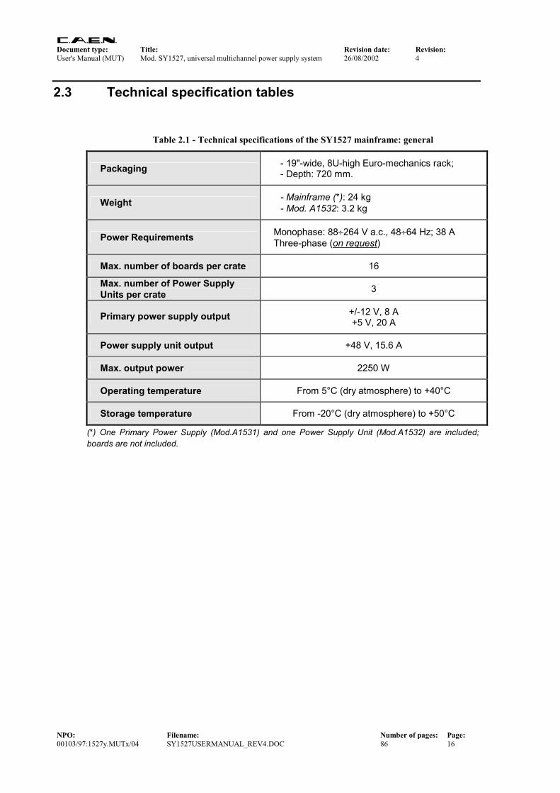
Table 2.1 - Technical specifications of the SY1527 mainframe: general
Packaging - 19"-wide, 8U-high Euro-mechanics rack; - Depth: 720 mm.
Weight - Mainframe (*): 24 kg - Mod. A1532: 3.2 kg
Power Requirements Monophase: 88÷264 V a.c., 48÷64 Hz; 38 A Three-phase (on request)
Max. number of boards per crate 16
Max. number of Power Supply Units per crate 3
Primary power supply output +/-12 V, 8 A +5 V, 20 A
Power supply unit output +48 V, 15.6 A
Max. output power 2250 W
Operating temperature From 5°C (dry atmosphere) to +40°C
Storage temperature From -20°C (dry atmosphere) to +50°C
(*) One Primary Power Supply (Mod.A1531) and one Power Supply Unit (Mod.A1532) are included; boards are not included.

Document type: Title: Revision date: Revision: User's Manual (MUT) Mod. SY1527, universal multichannel power supply system 26/08/2002 4
NPO: Filename: Number of pages: Page: 00103/97:1527y.MUTx/04 SY1527USERMANUAL_REV4.DOC 86 17
Table 2.2 - Technical specifications of the SY1527 mainframe: front and rear panel components
(refer to the figure in Appendix A)
Displays (I/O control section)
− GEN, red LED, lights up as GENERAL STATUS signal, corresponding to a logic combination (defined by the user) of OVC, UNV, OVV, TRIP, is TRUE;
− CH-ON, red LED, lights up as at least one channel is ON; − OVC, UNV, TRIP, OVV, red LEDs, light up as at least one channel is in Over
Current, Under Voltage, Trip, Over Voltage condition, respectively; − RSTFLAG, red LED, lights up after a RESET; − CHK PASS, green LED, lights up as the initial system check has been performed
successfully and the system is ready. − VSEL, ISEL, green LEDs, light up as the relevant connectors for voltage and
current selection, respectively, are TRUE; − KILL, green LED, lights up as the system is in KILL condition; − NIM, TTL, green LEDs, light up as the relevant standard is selected; − RESET, red/orange LED, lights up as a RESET occurs: it is initially red and then
becomes orange, depending on the duration of the RESET signal; − LOCAL ENABLE, REM ENABLE, red LEDs, light up, respectively, as the Local
Enable mode is selected and as the Remote Enable mode is selected and the proper REM EN signal is sent in;
− OVERTEMP, FAN FAILURE, PWR FAILURE red LEDs, light up as the Over Temperature, Fan Failure and Power Failure condition, respectively, occurs;
− INTERLOCK, red LED, lights up as the system is in INTERLOCK condition. − LOCAL NET, CAENET, red LEDs, light up as the relevant connectors are in
activity; − MASTER, red LED, lights up as the HV SYNC clock is internally generated.
Displays (Power Supplies)
− OK, yellow LED, lights up as the system is turned on. − +5, +12, -12, +48, green LEDs, light up as the relevant power supply is present; − MAIN, orange LED, when alight, it warns that the system is connected to the
mains and the MAIN switch on the rear panel is in position 1.
Switches
− NIM/TTL switch for the selection of the level standard of the output signals; − LOCAL ENABLE/DISABLE/REMOTE ENABLE switch, which allows,
respectively, to enable the channels locally or to disable them or to allow their remote enable via the proper ENABLE input signal;
− INTERLOCK CLOSED/OPEN switch to select if the INTERLOCK function is active when the contact is closed or open, respectively.
− MAIN switch (rear panel) to power the Power Supply Section; − POWER ON key (front panel, primary power supply) to power on the system
locally or to enable its remote power on.
Buttons RESET push button: if TRESET > TRCPU = 100÷200 ms CPU is reset; if TRESET > TRCH = TRCPU+900 ms CPU, boards are reset and the channels are turned off. Reset must be enabled via software (RESET FLAG window, see §7.1.22).
Local Control Interfaces
− 7.7" colour LCD screen, with brightness and contrast control buttons; − 15-key keypad; − compact switch (8 directions + press action).
Remote Control Interfaces
− H.S. CAENET; − LOCAL NET (to control non-intelligent systems ONLY); − One PS/2 connector for external PC keyboard; − VGA-standard connector for external VGA monitor; − ETHERNET (TCP/IP); − RS232 interface for external VT100 or PC.
Optional Interfaces − CAN-bus.
Table 2.3 - Technical specifications of the SY1527 mainframe: input and output signals

Document type: Title: Revision date: Revision: User's Manual (MUT) Mod. SY1527, universal multichannel power supply system 26/08/2002 4
NPO: Filename: Number of pages: Page: 00103/97:1527y.MUTx/04 SY1527USERMANUAL_REV4.DOC 86 18
(refer to the figure in Appendix A)
VSEL: Std. NIM/TTL; 00-type LEMO connector. Function: channel voltage selection.
ISEL: Std. NIM/TTL; 00-type LEMO connector. Function: channel current selection.
RESET: Std. NIM/TTL; 00-type LEMO connector. Function: RESET from the front panel. If the duration of the RESET signal is > TRCPU=100÷200 ms, the CPU is reset; if it is > TRCH= TRCPU + 900 ms, also the boards are reset and the channels are turned off. Reset must be enabled via software (RESET FLAG window, see §7.1.22).
KILL: Std. NIM/TTL; 00-type LEMO connector. Function: KILL from the front panel: it turns all channels off.
ENABLE: Std. NIM/TTL; 00-type LEMO connector. Function: remote enable.
INTERLOCK: open/closed contact; 00-type LEMO connector. Function: INTERLOCK command: it turns all the channels off as it is open/closed, according to the position of the relevant switch.
INPU
TS
REMOTE IN: +12V, 50mA max., electric. insulated;tol.:-40%÷+20%;00LEMO connector. Function: remote power-on of the system.
OVC: Std. NIM/TTL (selectable); 00-type LEMO connector. Function: at least one channel is in Over Current.
UNV: Std. NIM/TTL (selectable); 00-type LEMO connector. Function: at least one channel is in Under Voltage.
OVV: Std. NIM/TTL (selectable); 00-type LEMO connector. Function: at least one channel is in Over Voltage.
CH-ON: Std. NIM/TTL (selectable); 00-type LEMO connector. Function: at least one channel is ON.
RST FLAG: Std. NIM/TTL (selectable); 00-type LEMO connector. Function: a RESET occurred according to user's settings (RESET FLAG window, see §7.1.22).
CHK PASSED: Std. NIM/TTL (selectable); 00-type LEMO connector. Function: initial system check successful and system ready.
TRIP: Std. NIM/TTL (selectable); 00-type LEMO connector. Function: at least one channel in Trip condition.
GEN: Std. NIM/TTL (selectable); 00-type LEMO connector. Function: GENERAL STATUS indication; corresponds to the logic combination (defined by the user) of OVC, UNV, OVV, TRIP.
OU
TPU
TS
REMOTE OUT: +12V level,refer. to the crate ground;tol.:-20%÷+20%;00LEMO connector. Function: remote power-on of the adjacent daisy-chained crate.
HVSYNC: Bidirectional differential signal ; 2-pin LEMO connectors. Function: sync clock for the PWS Units ((RS485 Std., 1.25 MHz).
LOCAL NET: Bidirectional differential signal; 2-pin LEMO connector. Function: LOCAL bus for the control of non-intelligent systems ONLY.
CAENET: Bidirectional CAENET; 00-type LEMO connector. Function: H.S. CAENET interface.
I/O
TRIP IN/OUT: Bidirectional differential signal; 5x2-flat connectors. Function: external TRIP lines to handle TRIP conditions.
All the above signals, except for the REMOTE IN/OUT, are referred to a common ground (COMMON GROUND) and are galvanically insulated up to 150 V with respect to the ground of the crate (CRATE GROUND).
Document type: Title: Revision date: Revision: User's Manual (MUT) Mod. SY1527, universal multichannel power supply system 26/08/2002 4
NPO: Filename: Number of pages: Page: 00103/97:1527y.MUTx/04 SY1527USERMANUAL_REV4.DOC 86 19
3. Safety information and operation requirements This section contains the fundamental safety rules for the installation and operation of the SY1527 system. Read thoroughly this section before starting any procedure of installation or operation of the product.
3.1 General information Review the following safety precautions to avoid injury and prevent damage to this product or any products connected to it. To avoid potential hazards, use the product only as specified. Only qualified personnel should perform service procedures.
3.1.1 Injury Precautions Use Proper Power Cord and HV Cables. To avoid fire hazard, use only the power cord and HV cables specified for this product. Avoid Electric Overload. To avoid electric shock or fire hazard, do not apply a voltage to a load that is outside the range specified for that load. Avoid Electric Shock. To avoid injury or loss of life, do not connect or disconnect cables while they are connected to a voltage source. Ground the Product. This product is grounded through the grounding conductor of the power cord. To avoid electric shock, the grounding conductor must be connected to earth ground. Before making connections to any input or output terminals of the product, ensure that the product is properly grounded. Do Not Operate Without Covers. To avoid electric shock or fire hazard, do not operate this product with covers or panels removed. Do Not Operate in Wet/Damp Conditions. To avoid electric shock, do not operate this product in wet or damp conditions. Do Not Operate in an Explosive Atmosphere. To avoid injury or fire hazard, do not operate this product in an explosive atmosphere. Do not install the crates on top of each other. A minimum distance of 15 cm is required between the top of a crate and any other object over it.
Document type: Title: Revision date: Revision: User's Manual (MUT) Mod. SY1527, universal multichannel power supply system 26/08/2002 4
NPO: Filename: Number of pages: Page: 00103/97:1527y.MUTx/04 SY1527USERMANUAL_REV4.DOC 86 20
3.1.2 Product Damage Precautions Use Proper Power Source. Do not operate this product from a power source that applies more than the voltage specified. Provide Proper Ventilation. To prevent product overheating, provide proper ventilation. Do Not Operate With Suspected Failures. If you suspect there is damage to this product, have it inspected by qualified service personnel.
3.1.3 EC Certifications and Compliance Use in conformity of the definition with fully equipped mainframe with fully closed slots by boards or dummy panels. Sufficient cooling and mains connection must be secured according to regulations. Signal lines length during all tests was less than 3 m. The RS232 cable must be properly shielded and have a length of less than 3 m. Admitted for powering by industrial mains only.
3.1.4 Terms in this Manual These terms may appear in this manual: WARNING: Warning statements identify conditions or practices that could result in injury or loss of life. CAUTION: Caution statements identify conditions or practices that could result in damage to this product or other property.
3.2 Safety Terms and Symbols on the Product These terms may appear on the product: • DANGER indicates an injury hazard immediately accessible as you read the marking. • WARNING indicates an injury hazard not immediately accessible as you read the
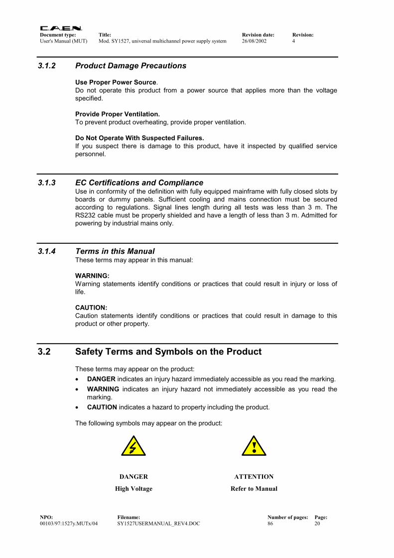
marking. • CAUTION indicates a hazard to property including the product. The following symbols may appear on the product:
DANGER ATTENTION
High Voltage Refer to Manual
Document type: Title: Revision date: Revision: User's Manual (MUT) Mod. SY1527, universal multichannel power supply system 26/08/2002 4
NPO: Filename: Number of pages: Page: 00103/97:1527y.MUTx/04 SY1527USERMANUAL_REV4.DOC 86 21
3.3 General Operation Requirements Before operation, check the following requirements:
Operating temperature: 5÷40°C (dry atmosphere)
Max. length of cables: according to cable specifications
Document type: Title: Revision date: Revision: User's Manual (MUT) Mod. SY1527, universal multichannel power supply system 26/08/2002 4
NPO: Filename: Number of pages: Page: 00103/97:1527y.MUTx/04 SY1527USERMANUAL_REV4.DOC 86 22
4. System and channel control
4.1 Introduction All the parameters' readout or modification requests coming from different sources (local control devices, video terminal, H. S. CAENET controller, etc.) are handled by the CPU of the system. The CPU also monitors the crate general parameters, such as H.S. CAENET Node address, RS232 Baud Rate, System Alarms and so on. The current system status is stored in a permanent memory (EEPROM) so that all this information is not lost at Power-Off. The Channel Boards as well house a microcontroller with its permanent memory (EEPROM) where it stores all the channels' parameters values. This feature allows easy upgrading and expansion of the system: new modules, or custom modules specially developed to fit the user’s needs, can be added to the system without modifying the system CPU firmware. The microcontroller has two main functions:
• control and monitoring of the channels of the board;
• communication with the system CPU. The following sections contain an overview of the commands, parameters and alarms for the control and monitoring of the system and board channels.
4.2 System control Several commands are available to control the system. These commands affect all the channels and can be sent to the system in different ways, depending on the type of command. The most common way to forward a command to the system is to sent a proper input signal through the relevant connector on the front panel; however, for some commands a hardware input, like a button or a switch, has been foreseen. The following sections are devoted to the description of the commands available. Unless differently specified, all input signals mentioned below are referred to a common ground (COMMON GROUND) and are galvanically insulated up to 150 V with respect to the ground of the crate (CRATE GROUND). For further details on electro-mechanical specifications of the components please refer to the Technical Specifications Section in the Hardware Installation Guide. A short summary of all front panel components is also given in Table 2.2 and Table 2.3 at page 17 and 17, respectively. For component location on the front panel please refer to the figure in Appendix A.

Document type: Title: Revision date: Revision: User's Manual (MUT) Mod. SY1527, universal multichannel power supply system 26/08/2002 4
NPO: Filename: Number of pages: Page: 00103/97:1527y.MUTx/04 SY1527USERMANUAL_REV4.DOC 86 23
4.2.1 NIM / TTL standard selection A two-position switch, located on the front panel, allows to select the standard for almost all the control output signals. Nominally, the switch position affects the standard of the OVC, UNV, OVV, CH-ON, RST FLAG, CHK PASSED, TRIP and GEN signals. The standard for the inputs on the front panel can be either NIM or TTL independently from the position of this switch. The two switch positions correspond to:
• Left position (NIM): NIM standard (relevant green LED alight)
• Right position (TTL): TTL standard (relevant green LED alight).
4.2.2 LOCAL/REMOTE Power-On The system can be powered on either locally or remotely. The POWER-ON key, located on the front panel of the Primary Power Supply, has three different positions:
• Central position (OFF): the system is turned off;
• Right position (LOCAL): the system is turned on locally;
• Left position (REMOTE): the system is enabled to be turned on remotely: the remote power on of the system will occur by sending a proper REMOTE IN input signal through the relevant connector.
The REMOTE IN input signal must be a +12 V input level (50 mA max.; tolerance: -40% ÷ +20%). As the REMOTE IN connector is supplied with +12 V, the REMOTE OUT connector provides itself a +12 V voltage level (with a delay of some seconds; tolerance: -20% ÷ +20%) that can be used to power on another crate remotely. This feature allows to power on many crates with a single signal. The OK yellow LED lights up as the system is powered on, either locally or remotely. N.B. The system can be turned on only if the MAIN switch on the rear panel is in the position 1.
4.2.3 LOCAL/REMOTE Channel Enable The channel outputs can be enabled either locally or remotely. A three-position lever switch (LOC ENABLE / REM ENABLE / DISABLE switch) allows for the selection of the enable mode:
• Central position (DISABLE): the channel outputs are disabled; • Upper position (LOC ENABLE): the channel outputs are enabled locally (LOC
ENABLE red LED on); • Lower position (REM ENABLE): the channel outputs can be enabled remotely:
the remote enable of the channel outputs will occur by sending a proper ENABLE input signal through the relevant connector (the REM ENABLE red LED is alight as the ENABLE signal is TRUE).
As the channels are enabled either locally or remotely, their output voltages of the channels which are ON increase up to the programmed value (V0SET or V1SET,

Document type: Title: Revision date: Revision: User's Manual (MUT) Mod. SY1527, universal multichannel power supply system 26/08/2002 4
NPO: Filename: Number of pages: Page: 00103/97:1527y.MUTx/04 SY1527USERMANUAL_REV4.DOC 86 24
according to the level of the VSEL input; refer to § 4.2.4, p.24) with the rate determined by the Ramp-Up parameter. The channels which are OFF will remain OFF. If the channels are disabled via the switch (DISABLE position), the output voltages of the channels which are ON drop to 0 at the rate determined by the Ramp-Down parameters. If then they are enable again, they restore the previous state bringing the output voltage to the programmed value at the rate determined by the Ramp-Up parameters.
4.2.4 VSEL command Two Voltage values can be programmed for each channel: V0SET and V1SET (see § 4.4.5 and 4.4.7, p.30). They are selected by the status of the VSEL input signal, according to the following:
VSEL input signal Selected Output voltage VSEL green LED VSEL False V0SET LED OFF VSEL True V1SET LED ON
When channels are switched from V0SET to V1SET or vice versa, the output voltage drifts from one value to the other at the rate programmed for each channel (Ramp-Up or Ramp-Down parameter).
4.2.5 ISEL command Two current limit values can be programmed for each channel: I0SET and I1SET (see § 4.4.6 and 4.4.8, p.30). They are selected by the status of the ISEL input signal, according to the following:
ISEL input signal Selected Current limit ISEL green LED ISEL False I0SET LED OFF ISEL True I1SET LED ON
4.2.6 KILL command The KILL input signal, sent through the relevant connector, allows to switch all the channels off at the maximum rate available, regardless of the Ramp-Down or other parameters. The relevant green LED will be alight as the KILL signal is True. The KILL command can be also forwarded via software from the Utility Kill menu. Please refer to § 7.1.15, p.59 for further details.
4.2.7 RESET command The RESET command allows via the RESET input signal or the RESET push-button to reset the system CPU and, optionally, to reset the boards and to turn all the channels off. The action of the RESET command depends on the duration of the signal or of the press action (refer to Fig. 4.1):
Document type: Title: Revision date: Revision: User's Manual (MUT) Mod. SY1527, universal multichannel power supply system 26/08/2002 4
NPO: Filename: Number of pages: Page: 00103/97:1527y.MUTx/04 SY1527USERMANUAL_REV4.DOC 86 25
RESET signalstarts up
RESET
CPU RESET BOARDS' RESET
100÷200 ms 900 ms
TRCPU
TRCH
time
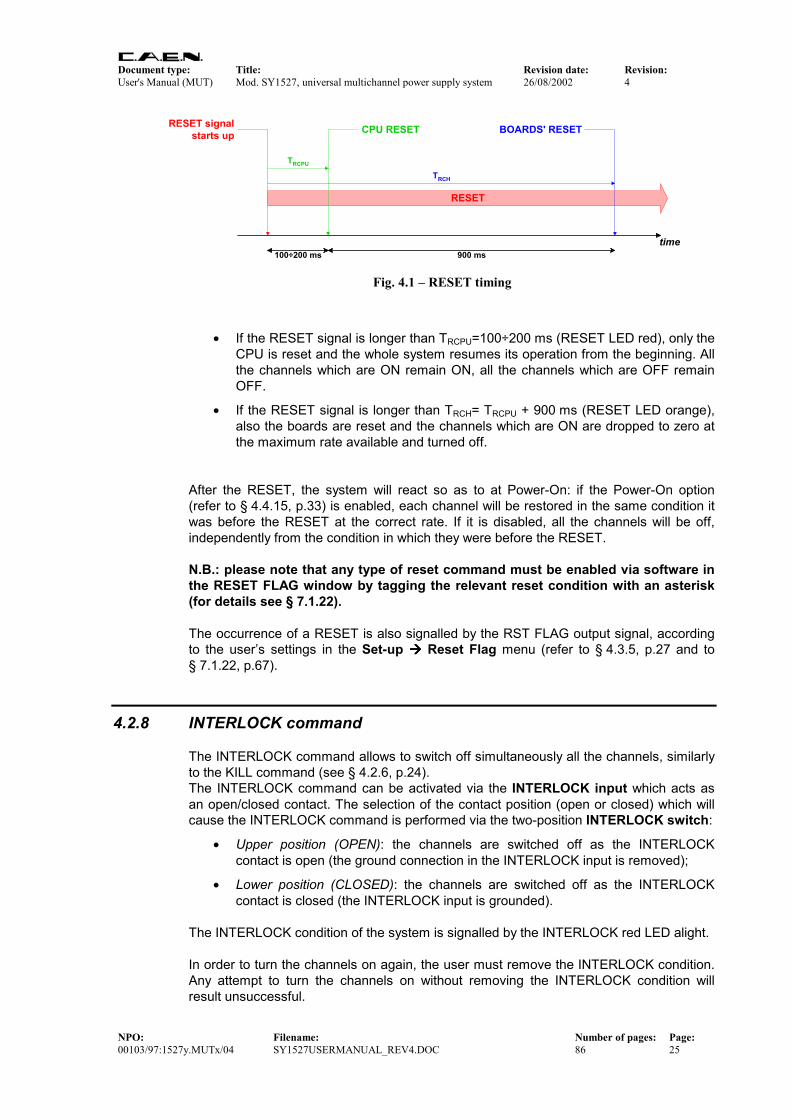
Fig. 4.1 – RESET timing
• If the RESET signal is longer than TRCPU=100÷200 ms (RESET LED red), only the CPU is reset and the whole system resumes its operation from the beginning. All the channels which are ON remain ON, all the channels which are OFF remain OFF.
• If the RESET signal is longer than TRCH= TRCPU + 900 ms (RESET LED orange), also the boards are reset and the channels which are ON are dropped to zero at the maximum rate available and turned off.
After the RESET, the system will react so as to at Power-On: if the Power-On option (refer to § 4.4.15, p.33) is enabled, each channel will be restored in the same condition it was before the RESET at the correct rate. If it is disabled, all the channels will be off, independently from the condition in which they were before the RESET. N.B.: please note that any type of reset command must be enabled via software in the RESET FLAG window by tagging the relevant reset condition with an asterisk (for details see § 7.1.22). The occurrence of a RESET is also signalled by the RST FLAG output signal, according to the user’s settings in the Set-up Reset Flag menu (refer to § 4.3.5, p.27 and to § 7.1.22, p.67).
4.2.8 INTERLOCK command The INTERLOCK command allows to switch off simultaneously all the channels, similarly to the KILL command (see § 4.2.6, p.24). The INTERLOCK command can be activated via the INTERLOCK input which acts as an open/closed contact. The selection of the contact position (open or closed) which will cause the INTERLOCK command is performed via the two-position INTERLOCK switch:
• Upper position (OPEN): the channels are switched off as the INTERLOCK contact is open (the ground connection in the INTERLOCK input is removed);
• Lower position (CLOSED): the channels are switched off as the INTERLOCK contact is closed (the INTERLOCK input is grounded).
The INTERLOCK condition of the system is signalled by the INTERLOCK red LED alight. In order to turn the channels on again, the user must remove the INTERLOCK condition. Any attempt to turn the channels on without removing the INTERLOCK condition will result unsuccessful.

Document type: Title: Revision date: Revision: User's Manual (MUT) Mod. SY1527, universal multichannel power supply system 26/08/2002 4
NPO: Filename: Number of pages: Page: 00103/97:1527y.MUTx/04 SY1527USERMANUAL_REV4.DOC 86 26
4.2.9 HV SYNC HVSYNC is the synchronisation clock for the Power Supply Units (RS485 standard, 1.25 MHz). It can works either as MASTER (MASTER red LED on), i.e. the synchronisation clock is internally generated and the HVSYNC connector works as output, or as SLAVE (MASTER red LED off), i.e. the synchronisation clock is externally generated and sent through the HV SYNC connector which works as input. For the relative settings please refer to the Set-Up HV Clock Conf. menu (§ 7.1.27, p.70).
4.3 System status monitoring Several output signals and alarms are available to monitor the system status, as described in the following subsections. Please note that all output signals mentioned below, unless differently specified, are referred to a common ground (COMMON GROUND) and are galvanically insulated up to 150 V with respect to the ground of the crate (CRATE GROUND). For further details on electro-mechanical specifications of the components please refer to the Technical Specifications Section in the Hardware Installation Guide. A short summary of all front panel components is also given in Table 2.2 and Table 2.3 at page 17 and 17, respectively. For component location on the front panel please refer to the figure in Appendix A.
4.3.1 Over Current
The Over Current condition (OVC) occurs when at least one channel is in Over Current condition, i.e. at least one channel has reached the current limit. The Over Current condition is signalled by the OVC output signal True and the relevant red LED on. The system detects this condition as a fault and reacts according to the setting of the TRIP parameter (see § 4.4.13, p.32 for its definition), namely: 1) TRIP = 1000 (constant CURRENT mode)
If the Board has programmable current hardware protections, the output voltage is varied to keep the current below the programmed limit (I0SET or I1SET, according to the ISEL signal level). The channel behaves like a current generator. If the Board has fixed current hardware protections, the output current is permitted to exceed the ISET value; the channel behaves like a current generator only if the maximum current value is reached.
2) 0 < TRIP < 1000 (TRIP mode) In this case, the channel behaves as in the constant CURRENT mode for a time equal to the finite value set as TRIP parameter, and then it is switched off according to the selected Power-Down option (KILL/RAMP). If the Kill option is selected, the channel will be switched off at the maximum rate available. If the Ramp option is selected, the voltage will drop to zero at a rate determined by the value of the Ramp parameter programmed for that channel.
Document type: Title: Revision date: Revision: User's Manual (MUT) Mod. SY1527, universal multichannel power supply system 26/08/2002 4
NPO: Filename: Number of pages: Page: 00103/97:1527y.MUTx/04 SY1527USERMANUAL_REV4.DOC 86 27
4.3.2 Under Voltage The Under Voltage condition (UNV) occurs when at least one channel is in Under Voltage condition, i.e. when:
• the actual value of the channel output voltage is lower than the programmed value.
The Under Voltage condition is signalled by the UNV output signal True and the relevant red LED on.
4.3.3 Over Voltage The Over Voltage condition occurs when at least one channel is in Over Voltage condition, i.e. when:
• the actual value of the channel output voltage is higher than the programmed value.
The Over Voltage condition is signalled by the OVV output signal True and the relevant red LED on.
4.3.4 Trip The TRIP condition occurs as at least one channel has tripped and has been switched off due to an Over Current condition (see § 4.3.1, p.26). This condition is signalled by the TRIP output signal which is asserted True and the relevant red LED alight. To recover from this state it is sufficient to turn the tripped channel On again or to execute a clear alarm command via software.
4.3.5 Reset flag RST FLAG (RESET FLAG) output signal is TRUE (and relevant red LED on) after a RESET occurred, according to the user’s settings. The type of reset which asserts RST FLAG TRUE can actually be selected via the Set-up Reset Flag menu (see § 7.1.22).
4.3.6 Check passed CHK PASS (CHECK PASSED) output signal is True (and the relevant green LED on) when the initial check of the system is successful and the system is ready. At normal operation, this signal is True and the relevant green LED is ON. This output signal becomes false either as the Fan failure LED is alight or as the Power failure LED is alight. As the condition which caused the CHECK PASSED being FALSE is remove, the CHECK PASSED signal becomes true again.

Document type: Title: Revision date: Revision: User's Manual (MUT) Mod. SY1527, universal multichannel power supply system 26/08/2002 4
NPO: Filename: Number of pages: Page: 00103/97:1527y.MUTx/04 SY1527USERMANUAL_REV4.DOC 86 28
4.3.7 GEN GEN (GENERAL STATUS) output signal is True (and relevant red LED on) according to a logic combination of OVC, UNV, OVV and TRIP. The logic combination of these conditions is defined by the user via the Status command in the Utility menu.
Refer to § 7.1.17, p.61 for further details.
4.3.8 CH-ON CH-ON (CHANNEL ON) output signal is True (and the relevant red LED on) as at least one channel is ON (i.e. the channels are enabled and the POWER parameter of that channel is set to ON; see § 4.4.14, p.32).
4.3.9 Over Temperature Over Temperature condition occurs when there is at least one board at a temperature out of the range TMIN ÷ TMAX, where TMIN and TMAX are two parameters depending on the board type (e.g., in the Mod. A1734 TMIN = 5°C and TMAX = 65°C). As the Over Temperature condition is reached, the relevant front panel LED lights up.
4.3.10 Fan Failure Fan Failure condition occurs when at least one of the 6 fans of the system has stopped or is turning below 20% of normal speed. As the Fan Failure condition is reached, the relevant front panel LED lights up.
4.3.11 Pwr Failure Power Failure condition occurs when there is a fault in the voltage supplies at the +12 V, -12 V or +48 V level. As the Power Failure condition is reached, the relevant front panel LED lights up.

Document type: Title: Revision date: Revision: User's Manual (MUT) Mod. SY1527, universal multichannel power supply system 26/08/2002 4
NPO: Filename: Number of pages: Page: 00103/97:1527y.MUTx/04 SY1527USERMANUAL_REV4.DOC 86 29
4.4 Channel Parameters Several parameters are associated with each channel, the number and type of these parameters depending on the Board type. They can be programmed and monitored in different ways:
• via local control devices (Local Control) i.e. the LCD screen, the Keypad and the Compact Switch;
• via remote control devices (Remote Control) by using the interfaces provided with the system, such as the PS/2 connector, the RS232 interface, the H. S. CAENET link, etc.;
The following subsections contains a short description of all parameters associated with a standard HV Power Supply Board (HV PWS Board, Mod. A1734). Although the number and type of parameters associated to each channel depend on the board's model, the following includes almost all parameters you can find when using a CAEN PWS Board.
4.4.1 CHANNEL NUMBER (CH #) CH # is the physical name of the channel which corresponds to its complete address (refer to Fig. 4.2). A channel in each crate is therefore identified by three items:
• the number of the cluster to which the crate where the board is inserted belongs;
• the number of the slot in which the board is plugged;
• the number of the channel on the board. For example, the channel 3 of the board plugged in the slot 5 of the SY1527 crate belonging to the cluster 0 is identified with the name "0.05.003". This parameter is read out by the software and is always shown in the channels window (refer to § 7.1.9, p.50). It cannot be modified by the user.
0.01.003
Cluster to which thecrate belongs
Slot into which theboard of the relevantchannel is plugged
Number of the relevantchannel on the board
Fig. 4.2 – Complete Channel address

Document type: Title: Revision date: Revision: User's Manual (MUT) Mod. SY1527, universal multichannel power supply system 26/08/2002 4
NPO: Filename: Number of pages: Page: 00103/97:1527y.MUTx/04 SY1527USERMANUAL_REV4.DOC 86 30
4.4.2 CHANNEL NAME (CHANNEL) It is the symbolic name of the channel and, up to now, can be modified only via Remote Control. It may be up to 11 characters long and may contain any of the following characters: "0..9", "A..Z", "a..z", "#", "&", "%", "$", "*", "_" and "-".
NOTICE!
PRESENTLY, AN EXTERNAL KEYBOARD IS MANDATORY TO INPUT THE
ALPHANUMERICAL DATA!
4.4.3 VMAX HARDWARE (HVMAX) It is a hardware Voltage limit. Usually, it is fixed through a potentiometer placed on the board front panel and, consequently, cannot be modified via software.
4.4.4 VMAX SOFTWARE (SVMAX) It is the maximum Voltage value programmable for the channel. It can be programmed either via Local or Remote Control.
4.4.5 V0SET It is the first of the two allowed Voltage programmable values (in absolute value). It is active when the VSEL input signal is FALSE. It can be programmed either via Local or Remote Control.
4.4.6 I0SET It is the first of the two allowed Current Limit programmable values (in absolute value). It is active when the ISEL input signal is FALSE. It can be programmed either via Local or Remote Control.
Document type: Title: Revision date: Revision: User's Manual (MUT) Mod. SY1527, universal multichannel power supply system 26/08/2002 4
NPO: Filename: Number of pages: Page: 00103/97:1527y.MUTx/04 SY1527USERMANUAL_REV4.DOC 86 31
4.4.7 V1SET It is the second of the two allowed Voltage programmable values (in absolute value). It is active when the VSEL input signal is TRUE. It can be programmed either via Local or Remote Control.
4.4.8 I1SET It is the second of the two allowed Current Limit programmable values (in absolute value). It is active when the ISEL input signal is TRUE. It can be programmed either via Local or Remote Control.
4.4.9 RAMP-UP (RUp) Maximum Voltage programmable increase rate expressed in Volt/second. When a channel is switched On, or when it is switched from a lower Voltage value to a higher one, the Voltage output drifts from one value to the other at the rate expressed by the Ramp-Up parameter. It can be programmed either via Local or Remote Control.
4.4.10 RAMP-DOWN (RDwn) Maximum Voltage programmable decrease rate expressed in Volt/second (in absolute value). When a channel is switched Off, or when it is switched from a higher Voltage value to a lower one, the Voltage output drifts from one value to the other at the rate expressed by the Ramp-down parameter. The output voltage of a channel drops to zero following the Ramp-down parameter when:
• the channel is switched Off (POWER Parameter = Off);
• the channel has tripped with 0< TRIP Parameter < 1000 (if the POWER-DOWN parameter is set to RAMP);
• the channels' outputs are disabled via the switch located on the front panel (LOC ENABLE/DISABLE/REM ENABLE switch).
It can be programmed either via Local or Remote Control.
4.4.11 VMON Voltage Monitored value. It can be monitored either via Local or Remote Control.
4.4.12 IMON
Document type: Title: Revision date: Revision: User's Manual (MUT) Mod. SY1527, universal multichannel power supply system 26/08/2002 4
NPO: Filename: Number of pages: Page: 00103/97:1527y.MUTx/04 SY1527USERMANUAL_REV4.DOC 86 32
Current Monitored value. It can be monitored either via Local or Remote Control.
4.4.13 TRIP It is the maximum time an Overcurrent condition is allowed to last. If an Overcurrent condition lasts for more than the programmed value, the System will react in the following ways: If Trip = 1000: Constant Current mode.
The over current condition may last indefinitely. If the Board has programmable current hardware protections, the output voltage is varied to keep the current below the programmed limit (I0SET or I1SET, according to the ISEL signal level). The channel behaves like a current generator. If the Board has fixed current hardware protections, the output current is permitted to exceed the ISET value; the channel behaves like a current generator only if the maximum current value is reached.
If 0 < Trip < 1000: Trip mode. The over current condition will cause the channel to "Trip": after an interval of time (equal to the Trip value) during which it behaves as in the constant CURRENT mode, the channel is switched off according to the selected POWER-DOWN option (KILL/RAMP). If the KILL option is selected, the channel will be switched off at the maximum rate available. If the RAMP option is selected, the voltage will drop to zero at a rate determined by the value of the RAMP parameter programmed for that channel.
The TRIP function is implemented by using a counter (TRIP counter) which is set to the programmed TRIP value each time one of the following actions is performed:
• the user sets the TRIP value;
• the user executes a clear alarm;
• the user powers on the channel (POWER parameter);
• otherwise, when the channel is no more in Over Current condition before the programmed TRIP value elapses.
This counter decreases as long as the channel is in Over Current condition and stops when one of the above conditions is met or the trip value is elapsed. The TRIP parameter can be programmed either via Local or Remote Control.
4.4.14 POWER (PW) It is the On/Off Status of the channel. If the INTERLOCK is not active and the channels are enabled (see LOCAL/REMOTE Enable), the channel is turned On by setting this parameter ON. As the channel is turned on, the output drifts from 0 to the programmed value (V0SET or V1SET according to the VSEL signal level) at the programmed rate (RAMP-UP parameter). It can be programmed either via Local or Remote Control.

Document type: Title: Revision date: Revision: User's Manual (MUT) Mod. SY1527, universal multichannel power supply system 26/08/2002 4
NPO: Filename: Number of pages: Page: 00103/97:1527y.MUTx/04 SY1527USERMANUAL_REV4.DOC 86 33
Setting the POWER parameter to ON automatically resets the alarm conditions. Moreover, it sets the TRIP counter again to its initial programmed value, so that the TRIP counter will start again from the programmed TRIP value as soon as another Over Current condition occurs. Refer to § 4.4.13, p.32 for further details on the TRIP counter.
4.4.15 POWER-ON (POn) This parameter controls the behaviour of the channel at Power-On or after a Restart. It can be set as:
• Enabled (EN),
• Disabled (DIS). If it is enabled, at Power-On or after a Restart each channel is restored in the same condition (defined by the POWER parameter) it was before the Power-Off or Reset. If this option is disabled, at Power-On or after a Restart all the channels are Off, independently from the condition in which they were before the Power-Off or Reset. It can be programmed either via Local or Remote Control.
4.4.16 POWER-DOWN (PDwn) This parameter affects the way the channels react at a Power-Off command caused by a TRIP condition. It can be set as:
• KILL,
• RAMP. If the KILL option is selected, the relevant channel will be switched off immediately. If the RAMP option is selected, the voltage will drop to zero at a rate determined by the value of the Ramp-Down parameter programmed for that channel. It can be programmed either via Local or Remote Control.
4.5 Channel status Several messages on the status of each channel are displayed by the User Software Interface and particularly in the Channels Window. For a list of these messages please refer to § 7.1.9, p.50.
4.6 Board status Several messages on the board status are displayed by the User Software Interface. In particular, in the Channels Window there is a column displaying the temperature

Document type: Title: Revision date: Revision: User's Manual (MUT) Mod. SY1527, universal multichannel power supply system 26/08/2002 4
NPO: Filename: Number of pages: Page: 00103/97:1527y.MUTx/04 SY1527USERMANUAL_REV4.DOC 86 34
detected on the PCB of the board (TEMP column) and another one displaying various messages on the board status. For a list of these messages please refer to § 7.1.9, p.50.

Document type: Title: Revision date: Revision: User's Manual (MUT) Mod. SY1527, universal multichannel power supply system 26/08/2002 4
NPO: Filename: Number of pages: Page: 00103/97:1527y.MUTx/04 SY1527USERMANUAL_REV4.DOC 86 35
5. System Power-On The Power-ON of the system can be performed either locally or remotely, as described in the following subsections.
5.1 Preliminary check Before powering the system, check that:
1. The Primary Power Supply and the Power Supply Units are inserted correctly in their relevant housings and fixed with the relevant screws (for details refer to § 7.1.1 in the Hardware Installation Guide);
2. The boards, after the required hardware settings (see the User’s Manual of the board), are plugged into the slots and fixed properly (for details refer to § 7.1.2 in the Hardware Installation Guide);
3. The crate is connected to the mains correctly (for details refer to § 7.1.3 in the Hardware Installation Guide);
4. Cabling has been performed according to the instructions given in § 7.4 in the Hardware Installation Guide, with reference to the chosen hardware set-up;
5. Safety instructions, installation requirements and operation requirements given in Section 6 of Hardware Installation Guide and in § 3.3, p.21 of this manual, respectively, have been thoroughly complied.
5.2 Local Power-On To power-On the system locally follow this procedure:
1. Turn on the MAIN switch located on the rear panel of the crate: the MAIN LED (orange), located on the front panel of the Primary Power Supply (refer to Front Panel figure in the Appendix), lights up.
2. Turn the Power-On key, located on the front panel of the Primary Power Supply (refer to Front Panel figure in the Appendix), in the right position (ON LOCAL): the OK LED (yellow), located on the front panel of the Primary Power Supply, lights up and the fan tray unit starts to work.
Following these operations, the following LEDs will be alight on the front panels of the Primary Power Supply (PPS) and of the Power Supply Units (PSUs) (refer to Front Panel figure in the Appendix):
+5 (green LED on PPS): it indicates the presence of +5 V power supply; if it is off it indicates that there is a fault.
+12 (green LED on PPS): it indicates the presence of +12 V power supply; if it is off it indicates that there is a fault.
-12 (green LED on PPS): it indicates the presence of -12 V power supply; if it is off it indicates that there is a fault.
Document type: Title: Revision date: Revision: User's Manual (MUT) Mod. SY1527, universal multichannel power supply system 26/08/2002 4
NPO: Filename: Number of pages: Page: 00103/97:1527y.MUTx/04 SY1527USERMANUAL_REV4.DOC 86 36
+48 (green LED on PSU): it indicates the presence of +48 V power supply; if it is off it indicates that there is a fault.
After the initial check of the system, the Welcome Screen of the User Software Interface will appear on the LCD screen (refer to Fig. 7.3, p.45).
5.3 Remote Power-On To power-On the system remotely follow this procedure:
1. Turn on the MAIN switch located on the rear panel of the crate: the MAIN LED (orange), located on the front panel of the Primary Power Supply (refer to Front Panel figure in the Appendix), lights up.
2. Turn the Power-On key, located on the front panel of the Primary Power Supply (refer to Front Panel figure in the Appendix), in the left position (ON REMOTE);
3. Send a proper signal (refer to § 4.2.2, p.23 for details) through the REMOTE IN input connector on the front panel of the Primary Power Supply: the OK LED (yellow), located on the front panel of the Primary Power Supply, will light up and the fan tray unit starts to work.
Following these operations, the LEDs listed below will be alight on the front panels of the Primary Power Supply (PPS) and of the Power Supply Units (PSUs) (refer to Front Panel figure in the Appendix):
+5 (green LED on PPS): it indicates the presence of +5 V power supply; if it is off it indicates that there is a fault.
+12 (green LED on PPS): it indicates the presence of +12 V power supply; if it is off it indicates that there is a fault.
-12 (green LED on PPS): it indicates the presence of -12 V power supply; if it is off it indicates that there is a fault.
+48 (green LED on PSU): it indicates the presence of +48 V power supply; if it is off it indicates that there is a fault.
After the initial check of the system, the Welcome Screen of the User Software Interface will appear on the LCD screen (refer to Fig. 7.3, p.45).
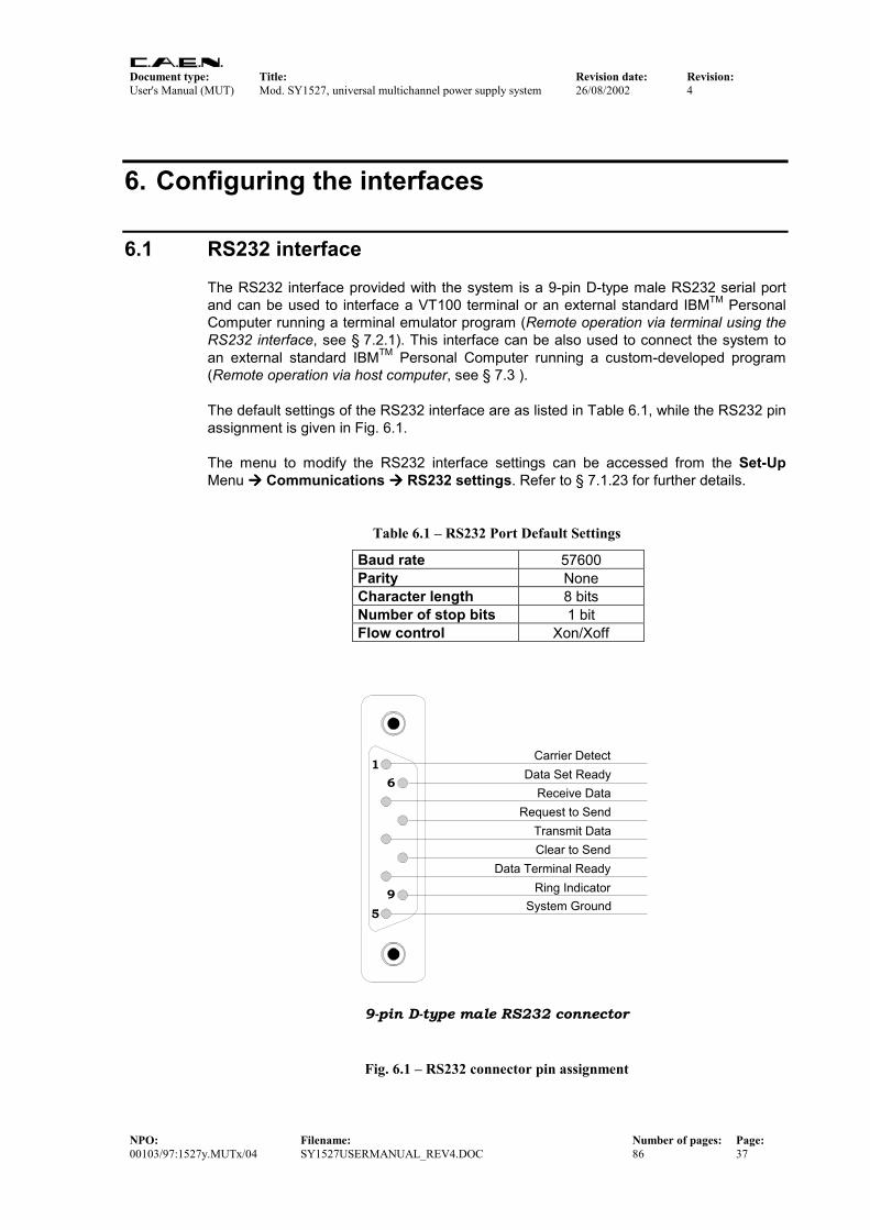
Document type: Title: Revision date: Revision: User's Manual (MUT) Mod. SY1527, universal multichannel power supply system 26/08/2002 4
NPO: Filename: Number of pages: Page: 00103/97:1527y.MUTx/04 SY1527USERMANUAL_REV4.DOC 86 37
6. Configuring the interfaces
6.1 RS232 interface The RS232 interface provided with the system is a 9-pin D-type male RS232 serial port and can be used to interface a VT100 terminal or an external standard IBMTM Personal Computer running a terminal emulator program (Remote operation via terminal using the RS232 interface, see § 7.2.1). This interface can be also used to connect the system to an external standard IBMTM Personal Computer running a custom-developed program (Remote operation via host computer, see § 7.3 ). The default settings of the RS232 interface are as listed in Table 6.1, while the RS232 pin assignment is given in Fig. 6.1. The menu to modify the RS232 interface settings can be accessed from the Set-Up Menu Communications RS232 settings. Refer to § 7.1.23 for further details.
Table 6.1 – RS232 Port Default Settings
Baud rate 57600 Parity None Character length 8 bits Number of stop bits 1 bit Flow control Xon/Xoff
9-pin D-type male RS232 connector
1
59
6Receive Data
Request to Send
Clear to SendData Terminal Ready
System Ground
Carrier Detect
Transmit Data
Data Set Ready
Ring Indicator
Fig. 6.1 – RS232 connector pin assignment
Document type: Title: Revision date: Revision: User's Manual (MUT) Mod. SY1527, universal multichannel power supply system 26/08/2002 4
NPO: Filename: Number of pages: Page: 00103/97:1527y.MUTx/04 SY1527USERMANUAL_REV4.DOC 86 38
6.2 Ethernet interface (TCP/IP protocol) The Ethernet connector provided with the system is a 10baseT connector and can be used to interface the SY1527 system to an Ethernet LAN. This allows the system control via an external standard IBMTM Personal Computer running a Telnet Client terminal emulator program (Remote operation via terminal using the TCP/IP protocol, see § 7.2.3) or to a computer connected to a TCP/IP network (INTERNET/INTRANET) and running a custom-developed program (Remote operation via host computer, see § 7.3).
6.2.1 Configuring the SY 1527 System for network connection Before establishing a connection to a TCP/IP network, a specific IP Address, IP Net Mask must be assigned by the local Network Administrator to the SY 1527 System. The default settings of the TCP/IP protocol for the SY 1527 System are as listed in Table 6.2: the default settings correspond to the network connection inactive.
Table 6.2 – TCP/IP Protocol Default Settings
IP Address 0.0.0.0 IP Net Mask 0.0.0.0 Gateway 0.0.0.0
Default TCP/IP settings can be modified by the User in the Start Up Window selecting: Set-Up Menu Communications TCP/IP settings Refer to § 7.1.23 for further details. An example of possible TCP/IP settings is listed in the table below.
Table 6.3 – An example of TCP/IP Protocol Settings
IP Address 192.9.200.1 IP Net Mask 255.255.255.0 Gateway 0.0.0.0
If the User needs to connect to the SY 1527 system from outside the local network, a Gateway address has to be specified in the TCP/IP settings.
6.2.2 Configuring the host PC To configure the TCP/IP parameters of the host PC with Windows 9x select: Start Settings Control Panel Double-click on the Network icon in the Control Panel. Double-click on the TCP/IP line in the network dialog box then select Specify an IP address.
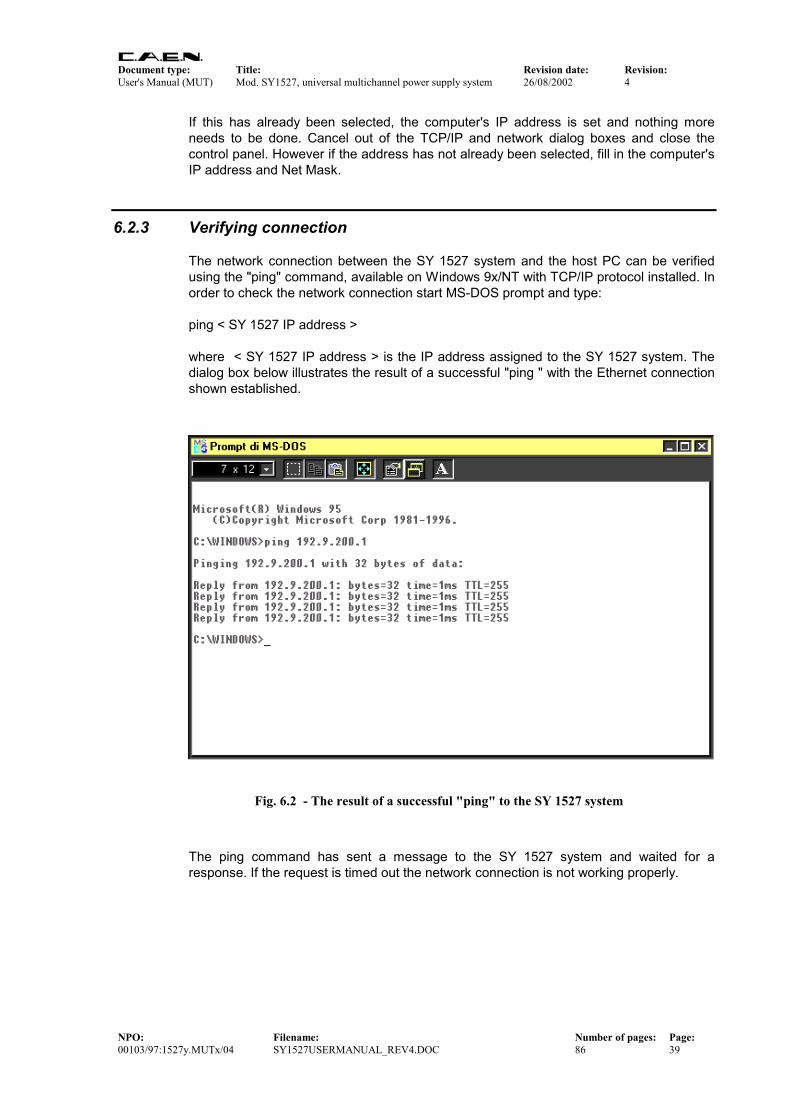
Document type: Title: Revision date: Revision: User's Manual (MUT) Mod. SY1527, universal multichannel power supply system 26/08/2002 4
NPO: Filename: Number of pages: Page: 00103/97:1527y.MUTx/04 SY1527USERMANUAL_REV4.DOC 86 39
If this has already been selected, the computer's IP address is set and nothing more needs to be done. Cancel out of the TCP/IP and network dialog boxes and close the control panel. However if the address has not already been selected, fill in the computer's IP address and Net Mask.
6.2.3 Verifying connection The network connection between the SY 1527 system and the host PC can be verified using the "ping" command, available on Windows 9x/NT with TCP/IP protocol installed. In order to check the network connection start MS-DOS prompt and type: ping < SY 1527 IP address > where < SY 1527 IP address > is the IP address assigned to the SY 1527 system. The dialog box below illustrates the result of a successful "ping " with the Ethernet connection shown established.
Fig. 6.2 - The result of a successful "ping" to the SY 1527 system
The ping command has sent a message to the SY 1527 system and waited for a response. If the request is timed out the network connection is not working properly.

Document type: Title: Revision date: Revision: User's Manual (MUT) Mod. SY1527, universal multichannel power supply system 26/08/2002 4
NPO: Filename: Number of pages: Page: 00103/97:1527y.MUTx/04 SY1527USERMANUAL_REV4.DOC 86 40
6.3 H.S. CAENET interface The H.S. CAENET interface provided with the system allows control via another SY1527 crate connected to an external standard Personal Computer via RS232 interface and running a terminal emulator program (Remote operation via terminal using the H.S. CAENET, i.e. Multicrate Operation, see § 7.2.2). The only H.S. CAENET interface setting concerns the crate number, i.e. the number assigned to the crate for its identification inside the H:S: CAENET daisy-chain (see § 7.1.23). Default setting is reported in Table 6.4. The menu to modify the H.S. CAENET settings can be accessed from Set-Up Menu Communications H.S. CAENET settings.
Table 6.4 – H.S. CAENET Default Settings
Crate Number 01
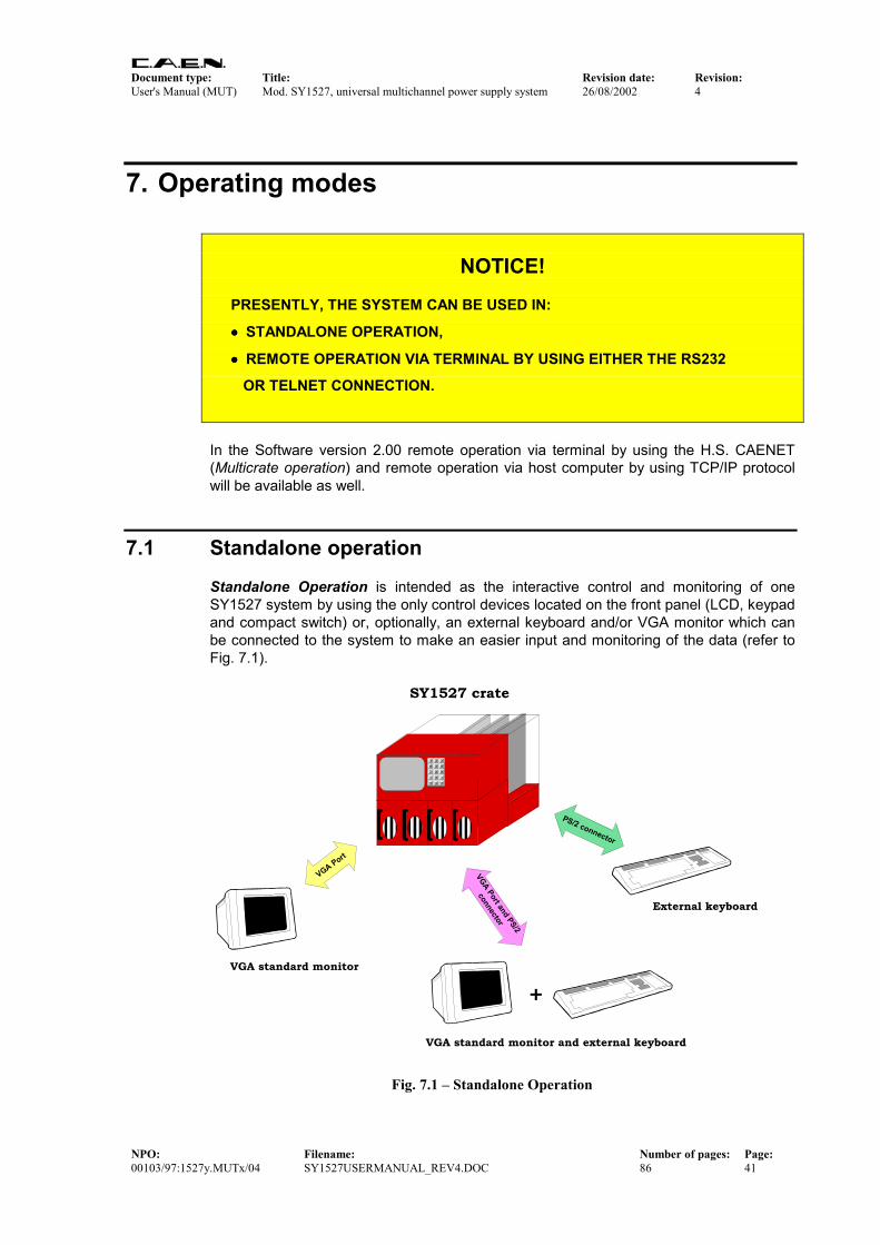
Document type: Title: Revision date: Revision: User's Manual (MUT) Mod. SY1527, universal multichannel power supply system 26/08/2002 4
NPO: Filename: Number of pages: Page: 00103/97:1527y.MUTx/04 SY1527USERMANUAL_REV4.DOC 86 41
7. Operating modes
NOTICE! PRESENTLY, THE SYSTEM CAN BE USED IN:
•••• STANDALONE OPERATION,
•••• REMOTE OPERATION VIA TERMINAL BY USING EITHER THE RS232
OR TELNET CONNECTION.
In the Software version 2.00 remote operation via terminal by using the H.S. CAENET (Multicrate operation) and remote operation via host computer by using TCP/IP protocol will be available as well.
7.1 Standalone operation Standalone Operation is intended as the interactive control and monitoring of one SY1527 system by using the only control devices located on the front panel (LCD, keypad and compact switch) or, optionally, an external keyboard and/or VGA monitor which can be connected to the system to make an easier input and monitoring of the data (refer to Fig. 7.1).
VGA Port
VGA standard monitor
SY1527 crate
1 2 3
44 5 67 8 9. 0 -
CMD DEL ACK
PS/2 connector
External keyboard
VGA standard monitor and external keyboard
VGA Port and PS/2
connector
+
Fig. 7.1 – Standalone Operation
Document type: Title: Revision date: Revision: User's Manual (MUT) Mod. SY1527, universal multichannel power supply system 26/08/2002 4
NPO: Filename: Number of pages: Page: 00103/97:1527y.MUTx/04 SY1527USERMANUAL_REV4.DOC 86 42
The keyboard can be plugged into one PS/2 connector located on the front panel, while the standard VGA monitor can be connected to the VGA port placed on the front panel. For further details on the electro-mechanical specifications refer to § 4.3.3 of the Technical Specifications Section in the Hardware Installation Guide.
NOTICE!
PRESENTLY, AN EXTERNAL KEYBOARD IS MANDATORY TO INPUT THE
ALPHANUMERICAL DATA!
7.1.1 Local Control Devices
7.1.1.1 LCD screen The crate is provided with a VGA-standard 7.7” colour LCD screen (640x480 resolution). Four buttons (+/- CONTRAST and +/- BRIGHT), placed just below the screen, allow to adjust the brightness and contrast of the monitor.
7.1.1.2 Keypad The keypad has 15 keys consisting of 10 numerical keys from “0” to “9”, the keys “.” and “-“, and the keys “CMD”, “DEL” and “ACK”. The latter are the COMMAND, DELETE and ACKNOWLEDGE commands, respectively. • The COMMAND key allows to select the Menu Bar at the top of the screen (see the
description of the Start Up Menu). • The DELETE key is the usual DELETE command. • The ACKNOWLEDGE key corresponds to the usual ENTER command. The relation between commands from Local Control Devices and commands from a standard keyboard are summarised in Table 7.1.
7.1.1.3 Compact Switch The compact switch, placed underneath the keypad on the front panel, can assume 8 positions plus the press action. The latter corresponds to the command SPACEBAR from the keyboard. The compact switch allows to: • move on the screen, by moving the lever toward one of its 8 directions; • switch among the options available for the currently selected field by pressing the
lever.

Document type: Title: Revision date: Revision: User's Manual (MUT) Mod. SY1527, universal multichannel power supply system 26/08/2002 4
NPO: Filename: Number of pages: Page: 00103/97:1527y.MUTx/04 SY1527USERMANUAL_REV4.DOC 86 43
Table 7.1 – Local control commands and external keyboard commands
Local control commands Keyboard commands CMD keypad key TAB key DEL keypad key DELETE key ACK keypad key ENTER key Compact Switch (press action) SPACE Bar Compact Switch (4 directions) Arrow keys
NOTICE UP TO NOW, THERE ARE ONLY 4 DIRECTIONS ENABLED (Up, Down, Right, Left)
TO MOVE ON THE SCREEN WITH THE COMPACT SWITCH!
7.1.2 Software Version The present description of the User Interface Software running on the SY1527 system refers to the:
Software Version 1.12.00 A variation in the last two figures (.00) of the software version refers to a debug operation; a variation in the two figures placed in the middle (.12.) refers to a feature upgrading of the software version; a variation in the first figure (1.) refers to a radical change of the software version.
Please pay particular attention to the NOTICE statements placed in the yellow
areas which underline features (mostly restrictions)
of this software version.

Document type: Title: Revision date: Revision: User's Manual (MUT) Mod. SY1527, universal multichannel power supply system 26/08/2002 4
NPO: Filename: Number of pages: Page: 00103/97:1527y.MUTx/04 SY1527USERMANUAL_REV4.DOC 86 44
7.1.3 Menu Structure At Power On in standalone configuration the User Interface Software will show a Welcome Screen. By pressing any key the Login Window will be shown and, after the Login procedures, the Start Up Window will appear. The Start Up Window has a Menu Bar at the top of the screen through which the user can access all the commands. The Menu structure is summarised in Fig. 7.2: the commands which appear in the Menu Bar of the Start Up Window are displayed as rounded squares with underneath the list of commands and windows which can be accessed. This Menu Bar is always present in all the windows: only in the Channels Window there are two further commands available in the Bar (Groups and View commands).
Welcomescreen
LoginWindow
Start UpWindow
ImplementedSoftware version 1.12
Not yet implemented
ViewUtility Set Up-
About
Session
Groups
Menu present in theChannels Window ONLY
ParametersGroup mode
Add Channels
Group 00
....
....
Group 15
Kill
Clear Alarm
Status
Trip Handling
Format
Board Upgrade
System Upgrade
Reset Flag
Communications
Security
Log Options
Tech Info
HV Clock Conf.
Channels
Crate Map
Connect
Log Out
Main
RemoveChannels
Fig. 7.2 – Menu Structure in standalone operation

Document type: Title: Revision date: Revision: User's Manual (MUT) Mod. SY1527, universal multichannel power supply system 26/08/2002 4
NPO: Filename: Number of pages: Page: 00103/97:1527y.MUTx/04 SY1527USERMANUAL_REV4.DOC 86 45
7.1.4 Welcome Window The Welcome Window which appears as the system is powered On is shown in Fig. 7.3.
Fig. 7.3 – Welcome Screen in Standalone Operation
7.1.5 Login Window The Login Window is shown in Fig. 7.4. In order to access the following Start Up Window, type the Username and the relevant Password in the relevant fields and then press ENTER (ACK key on the keypad). Presently, only a limited number of usernames and relevant passwords are accepted by the software. Refer to § 10.1 for a complete list of them and information about the relevant access level.
NOTICE! PRESENTLY, THERE IS A LIMITED NUMBER OF ACCEPTED INPUTS. PLEASE
REFER TO § 10.1 FOR A COMPLETE LIST OF THEM.

Document type: Title: Revision date: Revision: User's Manual (MUT) Mod. SY1527, universal multichannel power supply system 26/08/2002 4
NPO: Filename: Number of pages: Page: 00103/97:1527y.MUTx/04 SY1527USERMANUAL_REV4.DOC 86 46
Fig. 7.4 – Login Window
7.1.6 Start Up Window The Start Up Window is shown in Fig. 7.5. The Menu Bar at the top of the window allows to enter all the other windows available, according to the structure shown in Fig. 7.2, p.44. On the top right it is also reported the access level type (for example: User). The - menu gives access to:
• About, which displays the Welcome Screen; • Session, which visualises the Session Window. The Main menu gives access to:
• Channels, which displays the Channels Window; • Crate Map, which displays the Crate Map Window; • Connect, which is used for Multicrate Operation; • Logout, which goes back to the Welcome Screen. The Utility menu gives access to:
• Kill, which allows to kill all channels; • Clear Alarm, which allows to remove all alarm conditions; • Status, which allows to define the conditions to assert the GEN output signal; • Trip Handling, , which allows a sophisticated handling of trip conditions; • Format, which allows the format operation of the system flash memory;

Document type: Title: Revision date: Revision: User's Manual (MUT) Mod. SY1527, universal multichannel power supply system 26/08/2002 4
NPO: Filename: Number of pages: Page: 00103/97:1527y.MUTx/04 SY1527USERMANUAL_REV4.DOC 86 47
• Board Upgrade (visible only if you are logged as Administrator), which allows upgrading the board firmware;
• System Upgrade (visible only if you are logged as Administrator), which allows upgrading the system firmware.
The Setup menu gives access to:
• Reset Flag, which allows to enable the different reset conditions and to assert TRUE the RESET FLAG signal accordingly;
• Communications, which is used for interface settings; • Security, which allows the Administrator to configure multilevel user's profiles • Log Options, , which allows to visualise a log file; • Tech Info, which contains information about system operation; • HV Clock Conf. , used for the configuration of the crate as MASTER or SLAVE for
HV Clock synchronization.
Fig. 7.5 – Start Up Window
The following subsections contains a detailed description of each menu together with relevant commands and windows.

Document type: Title: Revision date: Revision: User's Manual (MUT) Mod. SY1527, universal multichannel power supply system 26/08/2002 4
NPO: Filename: Number of pages: Page: 00103/97:1527y.MUTx/04 SY1527USERMANUAL_REV4.DOC 86 48
7.1.7 The - Menu: About The About command, entered from the – menu that is the first on the left in the Menu Bar, displays the About Window (Fig. 7.6). It contains helpful information, nominally: • System Name: this is a descriptive name of the system. This name cannot be used
for the identification of the crate in Multicrate Operation. • Software Version: this is the software version presently running on the system
(Software Version 1.12.00). A variation in the last two figures (.00) of the software version refers to a debug operation; a variation in the two figures placed in the middle (.12.) refers to a feature upgrading of the software version; a variation in the first figure (1.) refers to a radical change of the software version.
To return to the Menu bar, press any key.
Fig. 7.6 – About Window

Document type: Title: Revision date: Revision: User's Manual (MUT) Mod. SY1527, universal multichannel power supply system 26/08/2002 4
NPO: Filename: Number of pages: Page: 00103/97:1527y.MUTx/04 SY1527USERMANUAL_REV4.DOC 86 49
7.1.8 The - Menu: Session The Session Window, entered from the – menu which is the first menu on the left in the Menu Bar, is shown in Fig. 7.7: it displays all the users (Username) presently connected to the system and gives information about their Access Level as Guest, User or Administrator (Level), the Communication Line (Comm Line) they are using and the Login Time, i.e. the time (day, month, hour, year) at which they started the connection. For example, Fig. 7.7 shows that there is only one user connected to the system. His Username is ‘user’, he is logged with a ‘user’ access Level and he is operating in standalone configuration (‘Local’ as Communication Line indicates that the user is currently connected to the system via no other interface but those compatible with the standalone operation: crate on-board control devices, external keyboard and external VGA monitor). The other communication line which can be displayed are: Telnet, RS232, CAENET, CMD RS232 and CMD TCP/IP. The latter two refer to a remote operation via host computer, i.e. using a command interface (CMD). To return to the Menu Bar, press any key.
Fig. 7.7 – Session Window
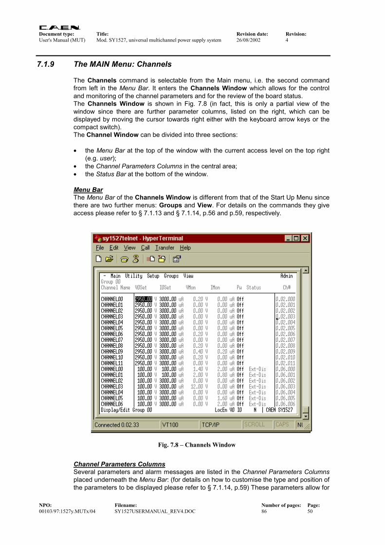
Document type: Title: Revision date: Revision: User's Manual (MUT) Mod. SY1527, universal multichannel power supply system 26/08/2002 4
NPO: Filename: Number of pages: Page: 00103/97:1527y.MUTx/04 SY1527USERMANUAL_REV4.DOC 86 50
7.1.9 The MAIN Menu: Channels The Channels command is selectable from the Main menu, i.e. the second command from left in the Menu Bar. It enters the Channels Window which allows for the control and monitoring of the channel parameters and for the review of the board status. The Channels Window is shown in Fig. 7.8 (in fact, this is only a partial view of the window since there are further parameter columns, listed on the right, which can be displayed by moving the cursor towards right either with the keyboard arrow keys or the compact switch). The Channel Window can be divided into three sections: • the Menu Bar at the top of the window with the current access level on the top right
(e.g. user); • the Channel Parameters Columns in the central area; • the Status Bar at the bottom of the window. Menu Bar The Menu Bar of the Channels Window is different from that of the Start Up Menu since there are two further menus: Groups and View. For details on the commands they give access please refer to § 7.1.13 and § 7.1.14, p.56 and p.59, respectively.
Fig. 7.8 – Channels Window
Channel Parameters Columns Several parameters and alarm messages are listed in the Channel Parameters Columns placed underneath the Menu Bar: (for details on how to customise the type and position of the parameters to be displayed please refer to § 7.1.14, p.59) These parameters allow for

Document type: Title: Revision date: Revision: User's Manual (MUT) Mod. SY1527, universal multichannel power supply system 26/08/2002 4
NPO: Filename: Number of pages: Page: 00103/97:1527y.MUTx/04 SY1527USERMANUAL_REV4.DOC 86 51
channel parameter setting and for status control of the channels and of the boards inserted into the crate. The parameters which can be set are displayed in a slight grey colour, the parameters which cannot be set but are just monitor parameters of the channel status or of the board status are white-coloured.
NOTICE! THE TYPES OF PARAMETERS AND ALARM MESSAGES
DISPLAYED IN THE CHANNELS WINDOW DEPENDS ON THE TYPE OF BOARD
USED: THE PARAMETERS AND ALARMS HERE BELOW REFER TO THE
MOD. A1734 HV PWS BOARD!
The parameters displayed in the Channels Window for each channel of each board are (from left to right):
• CHANNEL NAME (settable): descriptive name for the relevant channel.
• V0SET (settable): the first of the two allowed voltage programmable values.
• I0SET (settable): the first of the two allowed current limit programmable values.
• VMON (monitor): monitored voltage value.
• IMON (monitor): monitored current value.
• PW (settable ON/OFF): the Power parameter shows the ON/OFF channel status. As this parameter is set ON, the channel is switched on (if the INTERLOCK is not active and if the channel is enabled either locally or remotely).
• STATUS (monitor): it displays the channel status. Refer to § 7.1.9.1, p.53 for a list of the possible status which can be displayed here. The field becomes red if the channel is not in the steady status (normal operation). If the system is operated from an external terminal it blinks instead of being red.
• TRIP (settable): the TRIP parameter value, i.e. the maximum time an Over Current condition is allowed to last. Refer to § 4.4.13, p.32 for further details on the TRIP parameter.
• SVMAX (settable): the maximum voltage value programmable for the channel. If the value set as SVMAX is less than the current value of the V0SET/ V1SET parameter, the latter will automatically decrease to the SVMAX value.
• V1SET (settable): the second of the two allowed voltage programmable values.
• I1SET (settable): the second of the two allowed current limit programmable values.
• RDWn (settable): the Ramp-Down parameter value, i.e. the maximum voltage programmable decrease rate.
Document type: Title: Revision date: Revision: User's Manual (MUT) Mod. SY1527, universal multichannel power supply system 26/08/2002 4
NPO: Filename: Number of pages: Page: 00103/97:1527y.MUTx/04 SY1527USERMANUAL_REV4.DOC 86 52
• BdStatus (monitor): it displays the status of the board. Refer to § 7.1.9.2, p.54 for a list of the possible board status which can be displayed here.
• HVMAX (monitor): the hardware voltage limit for the board channels. It is adjusted via the relevant trimmer placed on the board front panel.
• TEMP (monitor): the temperature value detected on the board by the relevant sensor. If this value is out of the range TMIN ÷ TMAX, where TMIN and TMAX are the two threshold temperature parameters depending on the type of board, the system signals an Over Temperature condition (see § 4.3.9). Refer to the User’s Manual of the relevant board for further details.
• RUp (settable): the Ramp-Up parameter value, i.e. the maximum voltage programmable increase rate.
• POn (settable EN/DIS): Power-On option, which can be enabled or disabled. If this option is enabled, at Power-On or after a Restart each channel is restored in the same condition (defined by the Power parameter) it was before the Power-Off or Reset. If this option is disabled, at Power-On or after a Restart all the channels are off, independently from the condition in which they were before the Power-Off or Reset.
• PDwn (settable KILL/RAMP): Power-Down option, which can be set as KILL or RAMP. It affects the way the channels react at a Power-Off command caused by a TRIP condition. If the KILL option is selected, the relevant channel will be switched off at the maximum rate available. If the RAMP option is selected, the voltage will drop to zero at a rate determined by the value of the Ramp-Down parameter programmed for that channel.
• CH # (monitor): Channel address. It consists of three numbers (refer to Fig. 4.2): the first indicates the cluster to which the crate belongs, the second number indicates the slot where the relevant channel board is plugged into, and the third number identifies the number of the channel. Refer to § 2.1, p.10 for the definition of cluster. This field becomes red if the channel is not in a steady status (normal operation). If the system is operated from an external terminal it blinks instead of being red.
Both the compact switch or the arrow keys of a standard keyboard can be used to move through the columns containing the parameters. To return to the Menu Bar, press the TAB key (COMMAND key on the keypad). The channel parameters visualisation described above refer to the Group 00, which, by default, is the channel group containing all the channels available. It is also possible to display just a subset of the channels available by defining a different channel group. This operation is performed through the Groups menu in the Menu Bar displayed as the Channels Window is entered. This menu is fully explained in § 7.1.13, p.56. Moreover, it is possible to customise the number, type and position of the parameters to be displayed. This is done via the View menu, as described in § 7.1.14, p.59. Status Bar The Status Bar, located at the bottom of the window, provides some useful information, nominally (from left to right):
Document type: Title: Revision date: Revision: User's Manual (MUT) Mod. SY1527, universal multichannel power supply system 26/08/2002 4
NPO: Filename: Number of pages: Page: 00103/97:1527y.MUTx/04 SY1527USERMANUAL_REV4.DOC 86 53
• Operation type: it displays the type of operation which is running or which is presently selected in the Menu Bar.
• Loc En / Rem En: it displays if the channels are enabled locally (Loc En) or remotely (Rem En). If the channels are disabled, no information is displayed.
• V0 I0 / V1 I1: it displays if the channels are in the V0 I0 status (V0 I0) or in the V1 I1 status (V1 I1).
• I: the system is in INTERLOCK.
• K: the system is in KILL.
• T / N: it indicates if either the TTL (T) or the NIM (N) standard were selected via the relevant switch.
• : this red diamond is displayed if at least one channel is ON (i.e. at least one channel has the PW parameter set ON).
• CAEN SY1527: it blinks to indicate error of communication with a board plugged into the crate. If the communication error source is removed, the error status is reset (i.e. the CAEN SY1527 does not blink any more) by entering and then exiting the Crate Map window.
7.1.9.1 Channel Status The channel status messages which can be displayed in the Status parameter column of the Channels Window are as follows:
• Cal Err: Calibration Error: at least one of the calibrations for at least one of the channels is not correct.
• Up: the channel is ramping up.
• E Trip-Dwn: an external TRIP occurred: the channel is ramping down.
• I Trip-Dwn: an internal TRIP occurred: the channel is ramping down.
• OvC Dwn: an Over Current condition occurred: the channel is ramping down due to the intervention of the user (not for a TRIP condition).
• E Dis Dwn: an external DISABLE occurred: the channel is ramping down.
• Dwn: the channel is ramping down (only in the case that none of the E Trip-Dwn, I Trip-Dwn, OvC Dwn and E Dis Dwn conditions occurred).
• E Tripped: the channel is off due to an external TRIP.
• I Tripped: the channel is off due to an internal TRIP.
• Ext-Dis: the channel is off due to the fact that the board was disabled via the HV EN input connector on its front panel.
• OvC: the channel is in Over Current condition, i.e. the channel has reached the current limit.
• UnV: the channel is in Under Voltage condition, i.e. the actual value of the channel output voltage is lower than the programmed value.
• OvV: the channel is in Over Voltage condition, i.e. the actual value of the channel output voltage is higher than the programmed value.

Document type: Title: Revision date: Revision: User's Manual (MUT) Mod. SY1527, universal multichannel power supply system 26/08/2002 4
NPO: Filename: Number of pages: Page: 00103/97:1527y.MUTx/04 SY1527USERMANUAL_REV4.DOC 86 54
• HVmax: the channel output voltage has reached the HVMAX hardware voltage output limit.
This field becomes red if the channel is not in a steady status (normal operation). If the system is operated from an external terminal it blinks instead of being red.
7.1.9.2 Board Status The possible board status which can be displayed in the Bd Status column of the Channels Window are as follows:
• Pw Fault: power supply fault on the board.
• Fw Err: firmware error on the board.
• VMAX Cal Err: calibration error for the HVMAX parameter of the board.
• T Cal Err: calibration error for the temperature detection on the board. This field becomes red if the board is not in a steady status (normal operation). If the system is operated from an external terminal it blinks instead of being red.

Document type: Title: Revision date: Revision: User's Manual (MUT) Mod. SY1527, universal multichannel power supply system 26/08/2002 4
NPO: Filename: Number of pages: Page: 00103/97:1527y.MUTx/04 SY1527USERMANUAL_REV4.DOC 86 55
7.1.10 The MAIN Menu: Crate Map Crate Map is entered from the Main menu and opens the Crate Map Window showing what types of boards are inserted into the crate and in which slot they are plugged into. The Crate Map Window is shown in Fig. 7.9: the first column on the left indicates the number of the Slot (from 0 to 15) together with the model of the board inserted into the slot (if any). A short description of the board with its features and serial number follows the board model. Moreover, if there is an error of communication with a board inserted into a slot of the crate, the relevant board blinks. As soon as the error source is removed, the board stops blinking. Entering the Crate Map Window allows as well for the reset of communication error status, i.e. if the communication error source is removed and the Crate Map Window is entered, the CAEN SY1527 label in the status bar stops blinking on exiting the Crate Map Window. Conversely, if the communication error source has not been removed, the CAEN SY1527 label will go on blinking. To return to the Menu Bar, press any key.
Fig. 7.9 – Crate Map Window

Document type: Title: Revision date: Revision: User's Manual (MUT) Mod. SY1527, universal multichannel power supply system 26/08/2002 4
NPO: Filename: Number of pages: Page: 00103/97:1527y.MUTx/04 SY1527USERMANUAL_REV4.DOC 86 56
7.1.11 The MAIN Menu: Connect The Connect command allows to operate in Multicrate mode: it is possible to control via H.S. CAENET a remote slave Power Supply System. To establish the connection, it’s necessary to insert the remote system CAENET crate number (1 to 99) and then select Ok. Select Cancel to exit from the dialog window.
Fig.7.10 – Connect Window
7.1.12 The MAIN Menu: Logout As Logout is entered, the program goes back to the Welcome Screen. Refer to Fig. 7.3, p.45 for the layout of the Welcome Screen.
7.1.13 The GROUPS Menu and relevant commands The Groups Menu allows to create up to 15 different custom groups of channels (Group 01 through Group 15), containing a subset of the channels available. By default, the Group 00 is the group containing all the channels and cannot be edited. The Groups menu gives access to:
• Group mode toggle command, • Add Channels, • Remove Channels, • Group 00 through Group 15 windows. In order to create a new group, follow this procedure:
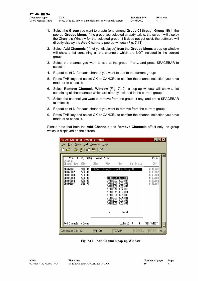
Document type: Title: Revision date: Revision: User's Manual (MUT) Mod. SY1527, universal multichannel power supply system 26/08/2002 4
NPO: Filename: Number of pages: Page: 00103/97:1527y.MUTx/04 SY1527USERMANUAL_REV4.DOC 86 57
1. Select the Group you want to create (one among Group 01 through Group 15) in the pop-up Groups Menu: if the group you selected already exists, the screen will display the Channels Window for the selected group; if it does not yet exist, the software will directly display the Add Channels pop-up window (Fig. 7.11);
2. Select Add Channels (if not yet displayed) from the Groups Menu: a pop-up window will show a list containing all the channels which are NOT included in the current group;
3. Select the channel you want to add to the group, if any, and press SPACEBAR to select it;
4. Repeat point 3. for each channel you want to add to the current group;
5. Press TAB key and select OK or CANCEL to confirm the channel selection you have made or to cancel it;
6. Select Remove Channels Window (Fig. 7.12): a pop-up window will show a list containing all the channels which are already included in the current group;
7. Select the channel you want to remove from the group, if any, and press SPACEBAR to select it;
8. Repeat point 6. for each channel you want to remove from the current group;
9. Press TAB key and select OK or CANCEL to confirm the channel selection you have made or to cancel it.
Please note that both the Add Channels and Remove Channels affect only the group which is displayed on the screen.
Fig. 7.11 – Add Channels pop-up Window
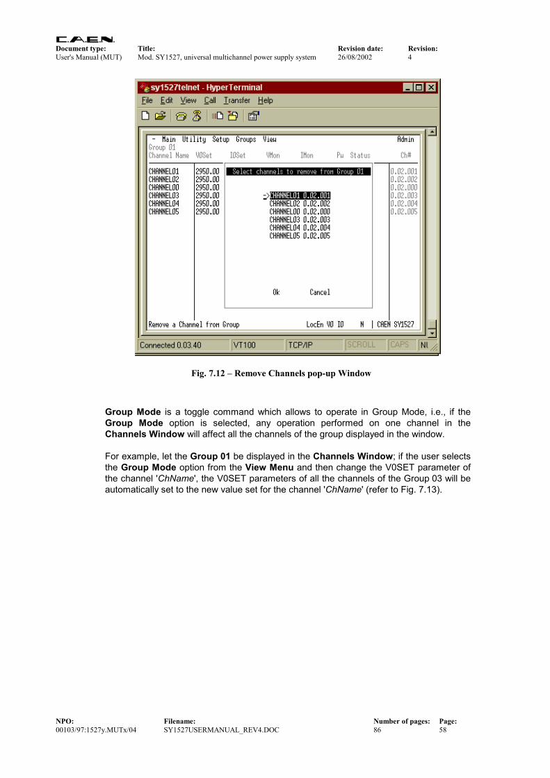
Document type: Title: Revision date: Revision: User's Manual (MUT) Mod. SY1527, universal multichannel power supply system 26/08/2002 4
NPO: Filename: Number of pages: Page: 00103/97:1527y.MUTx/04 SY1527USERMANUAL_REV4.DOC 86 58
Fig. 7.12 – Remove Channels pop-up Window
Group Mode is a toggle command which allows to operate in Group Mode, i.e., if the Group Mode option is selected, any operation performed on one channel in the Channels Window will affect all the channels of the group displayed in the window. For example, let the Group 01 be displayed in the Channels Window; if the user selects the Group Mode option from the View Menu and then change the V0SET parameter of the channel 'ChName', the V0SET parameters of all the channels of the Group 03 will be automatically set to the new value set for the channel 'ChName' (refer to Fig. 7.13).
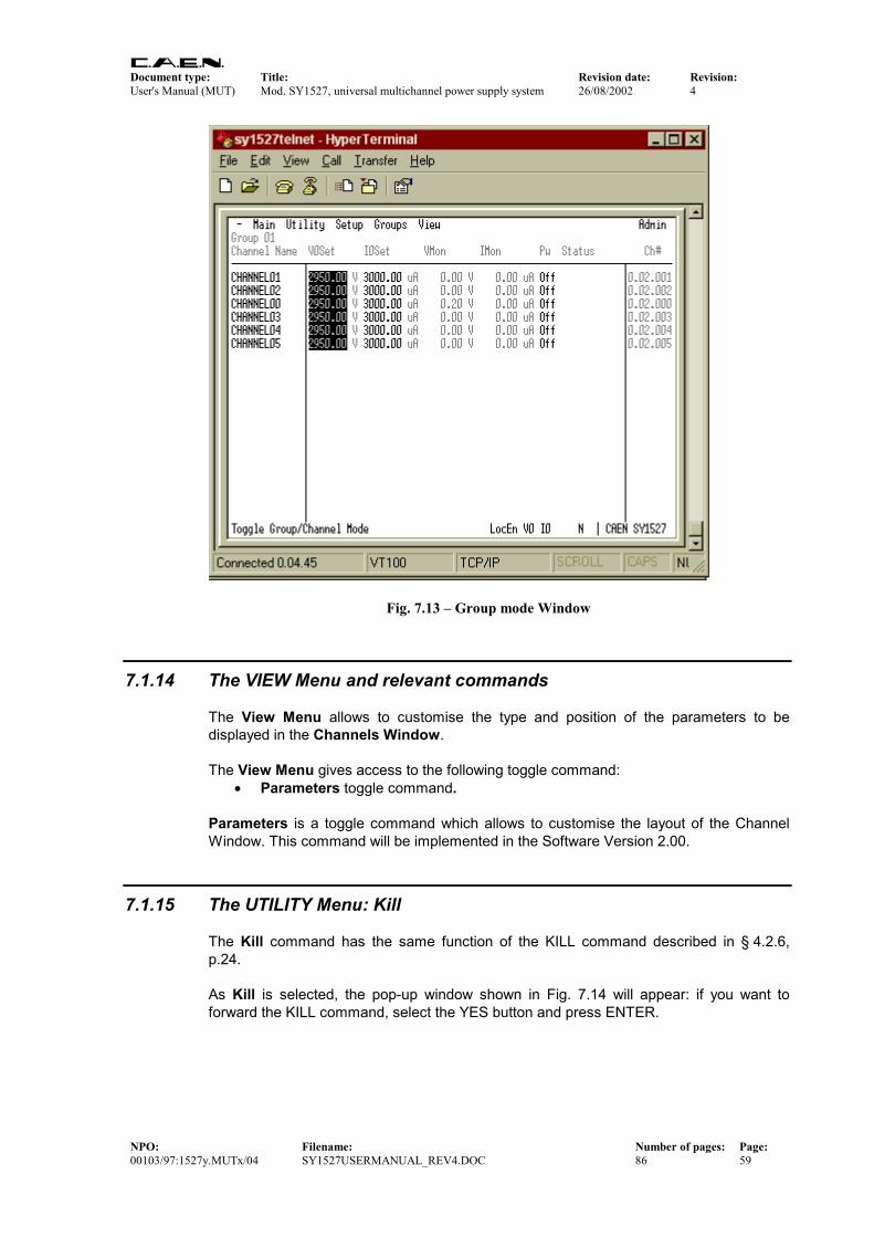
Document type: Title: Revision date: Revision: User's Manual (MUT) Mod. SY1527, universal multichannel power supply system 26/08/2002 4
NPO: Filename: Number of pages: Page: 00103/97:1527y.MUTx/04 SY1527USERMANUAL_REV4.DOC 86 59
Fig. 7.13 – Group mode Window
7.1.14 The VIEW Menu and relevant commands The View Menu allows to customise the type and position of the parameters to be displayed in the Channels Window. The View Menu gives access to the following toggle command:
• Parameters toggle command. Parameters is a toggle command which allows to customise the layout of the Channel Window. This command will be implemented in the Software Version 2.00.
7.1.15 The UTILITY Menu: Kill The Kill command has the same function of the KILL command described in § 4.2.6, p.24. As Kill is selected, the pop-up window shown in Fig. 7.14 will appear: if you want to forward the KILL command, select the YES button and press ENTER.
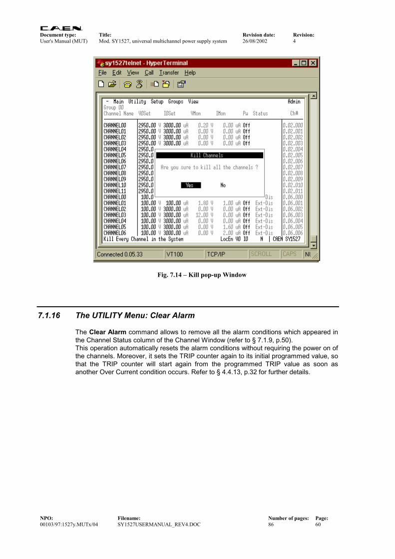
Document type: Title: Revision date: Revision: User's Manual (MUT) Mod. SY1527, universal multichannel power supply system 26/08/2002 4
NPO: Filename: Number of pages: Page: 00103/97:1527y.MUTx/04 SY1527USERMANUAL_REV4.DOC 86 60
Fig. 7.14 – Kill pop-up Window
7.1.16 The UTILITY Menu: Clear Alarm The Clear Alarm command allows to remove all the alarm conditions which appeared in the Channel Status column of the Channel Window (refer to § 7.1.9, p.50). This operation automatically resets the alarm conditions without requiring the power on of the channels. Moreover, it sets the TRIP counter again to its initial programmed value, so that the TRIP counter will start again from the programmed TRIP value as soon as another Over Current condition occurs. Refer to § 4.4.13, p.32 for further details.

Document type: Title: Revision date: Revision: User's Manual (MUT) Mod. SY1527, universal multichannel power supply system 26/08/2002 4
NPO: Filename: Number of pages: Page: 00103/97:1527y.MUTx/04 SY1527USERMANUAL_REV4.DOC 86 61
Fig. 7.15 – Clear Alarm pop-up Window
7.1.17 The UTILITY Menu: Status This command allows to define the condition to assert the GEN signal and light up the relevant LED (see § 4.3.7). Fig. 7.16 shows the pop-up window containing a list of quantities which allow to define the condition for asserting the GEN signal according to the following relation:
GEN = ENABLE ∧∧∧∧ (OVC ∨∨∨∨ OVV ∨∨∨∨ UNV ∨∨∨∨ ALWAYS) . To select any of these quantities insert an asterisk in the relevant field by using the arrows. Then select OK and press ENTER. ENABLE corresponds to enable the GEN signal generation and consequently must be always selected in order to assert the GEN signal. OVC, OVV, and UNV, are signals for system status monitoring (refer to § 4.3.1, 4.3.2, 4.3.3, p.26), If one or more of them are selected and the ENABLE is selected too, the GEN signal is asserted TRUE at the occurrence of any of the selected conditions. ALWAYS allows to assert the GEN signal TRUE anyway. If it is selected and the ENABLE is selected too, it asserts the GEN signal TRUE anyway, independently from the status of the other signals mentioned above (OVC, OVV and UNV).

Document type: Title: Revision date: Revision: User's Manual (MUT) Mod. SY1527, universal multichannel power supply system 26/08/2002 4
NPO: Filename: Number of pages: Page: 00103/97:1527y.MUTx/04 SY1527USERMANUAL_REV4.DOC 86 62
Fig. 7.16 – Status pop-up Window
7.1.18 The UTILITY Menu: Trip Handling This feature will be implemented in the Software Version 2.00 or later.
7.1.19 The UTILITY Menu: Format The Format command allows to format the flash memory of the system. In particular, it erases:
• all system settings;
• board firmware. To format the flash memory, select YES and press ENTER (refer to Fig. 7.17).

Document type: Title: Revision date: Revision: User's Manual (MUT) Mod. SY1527, universal multichannel power supply system 26/08/2002 4
NPO: Filename: Number of pages: Page: 00103/97:1527y.MUTx/04 SY1527USERMANUAL_REV4.DOC 86 63
Fig. 7.17 – Format pop-up Window
7.1.20 The UTILITY Menu: Board Upgrade This command opens the Board Upgrade pop-up window (Fig. 7.18) which allows to upgrade the firmware of the boards plugged into the crate. The window can be divided into two areas the upper one where there is the list of files present in the system flash memory, and the lower one where there is a list of the commands available. If there are no files in the flash memory, i.e. the upper list is empty, the files can be retrieved from a computer connected to the system via RS232 by using the terminal emulator program or a TFTP (Trivial File Transfer Protocol) Server Software1. The standard filename format from the factory for board firmware upgrade is as follows:
Board Firmware Filename = [boardname] . lmn Where [boardname] is the board model and lmn is the Firmware Release l.mn. For example, the file containing the Firmware Release 1.01 of the board Mod. A1734 will be named at the factory:
A1734.101
1 The TFTP Server is usually available on Unix workstations. In case of PCs with Windows 9x/NT, there are various shareware programs available on Internet, e.g. the program Pumpkin by the KLEVER GROUP INC. (www.klever.net).
Document type: Title: Revision date: Revision: User's Manual (MUT) Mod. SY1527, universal multichannel power supply system 26/08/2002 4
NPO: Filename: Number of pages: Page: 00103/97:1527y.MUTx/04 SY1527USERMANUAL_REV4.DOC 86 64
In order to add a file for board firmware upgrading in the system flash memory via RS232, follow this procedure:
1. check that the system is connected correctly via RS232 to a computer running a terminal emulator program;
2. enter the Utility menu Board Upgrade Add File (via RS232) of the SY1527 Software User Interface from the terminal emulator program: a pop up window will ask for the filename to add to the flash memory;
3. type the Filename you want to assign to the file you will load in the flash memory, select OK and press ENTER (the status Bar at the bottom of the window will display a Waiting data… message);
4. select Transfer Send Text File command in the Command Bar of the terminal emulator program (these commands are an example referring to the Hyperterminal of Win9x), browse in the directories and select the file you want to load in the flash memory; then click Open (the Status Bar will display a Downloading … message and finally Download completed.);
N.B.: if the user tries to add a file when the SY1527 system is operating in standalone configuration or if it is connected to a computer via TCP/IP protocol or H.S. CAENET instead of RS232, the software will show an error message (WARNING: only available via RS232 Terminal connection).
In order to add a file in the system flash memory via TFTP, follow this procedure:
1. check if the system is connected via TCP/IP protocol to a computer able to run a TFTP (Trivial File Transfer Protocol) Server Software and configured properly;
2. run the TFTP Server Software and select the directory containing the file you want to add;
3. enter the Utility menu Board Upgrade Add File (via TFTP) of the SY1527 Software User Interface (you can also be running the SY1527 software also via a type of connection different from the TCP/IP protocol): a pop up window will ask for the filename to add to the flash memory;
4. type the Filename you want to load in the flash memory (in this case the filename must be the real filename of the file you want to add), select OK and press ENTER;
5. type the IP Address of the computer where the file is, select OK and press ENTER (the Status Bar at the bottom of the window will display a Downloading … message and finally Download completed).
After you followed one of the two procedures, the new file is displayed in the list in the upper area of the Board Upgrade window. the file dimensions as well are shown beside the filename. It is possible to load up to three files in the system flash memory.

Document type: Title: Revision date: Revision: User's Manual (MUT) Mod. SY1527, universal multichannel power supply system 26/08/2002 4
NPO: Filename: Number of pages: Page: 00103/97:1527y.MUTx/04 SY1527USERMANUAL_REV4.DOC 86 65
Fig. 7.18 – Board Upgrade pop-up Window
In order to upgrade the firmware of the boards, it is now necessary to download the firmware on the board by using the Download Selected File on Board command. In order to upgrade the firmware on the board, follow these steps:
1. select the file you want to download by means of the arrows in the upper area of the Board Upgrade window;
2. Select the Download Selected File on Board command by means of the TAB key and then press enter: as this command is entered, the software will ask you for the slot where to download the firmware;
3. type the number of the Slot where the board you want to upgrade is plugged into, select OK and press ENTER: some messages displayed at the bottom of the window will indicate the on-going operations.
To erase a file from the flash memory select the Delete Selected File command and press ENTER. To exit the Board Upgrade window select the Exit command and press ENTER.
Document type: Title: Revision date: Revision: User's Manual (MUT) Mod. SY1527, universal multichannel power supply system 26/08/2002 4
NPO: Filename: Number of pages: Page: 00103/97:1527y.MUTx/04 SY1527USERMANUAL_REV4.DOC 86 66
7.1.21 The UTILITY Menu: System Upgrade In the system permanent memory there is always a running image which is that currently in use. However, a further image, called stored image, can be stored in the permanent memory as a spare image. This command opens the System Upgrade pop-up window (Fig. 7.19) which allows to memorise an image as stored image in the permanent memory and then to upgrade the firmware of the system by the Upgrade Running Image command. The window can be divided into two areas the upper one where there is the stored image (if any) presently loaded in the system flash memory, and the lower one where there is a list of commands. If the upper list is empty, the file can be retrieved from a computer connected to the system via TCP/IP protocol by using a TFTP (Trivial File Transfer Protocol) Server Software2. The standard image file format from the factory for system firmware upgrade is as follows:
System Firmware Filename = SY1527 - [software version] . bin Where [software version] is the number of software version separated by hyphens. For example, the file containing the System Firmware for the Software Version 1.12.00 will be named at the factory:
SY1527-1-12-00.bin In order to add a image file in the system flash memory via TFTP, follow this procedure:
1. check if the system is connected via TCP/IP protocol to a computer able to run a TFTP (Trivial File Transfer Protocol) Server Software and configured properly;
2. run the TFTP Server Software and select the directory containing the image file you want to add;
3. enter the Utility menu System Upgrade Download Image via TFTP of the SY1527 Software User Interface (you can be running the SY1527 software also via a type of connection different from the TCP/IP protocol): a pop up window will ask for the image filename to add to the flash memory;
4. type the Filename you want to load in the flash memory (the filename must be the real filename of the file you want to add), select OK and press ENTER;
5. type the IP Address of the computer where the image file is, select OK and press ENTER (the status Bar at the bottom of the window will display a Downloading … message and finally Download completed).
Now a image file is displayed in the window together with its dimensions and checksum. It is possible to load only one file in the system flash memory for system firmware upgrading.
2 The TFTP Server is usually available on Unix workstations. In case of PCs with Windows
9x/NT, there are various shareware programs available on Internet, e.g. the program Pumpkin by
the KLEVER GROUP INC. (www.klever.net).

Document type: Title: Revision date: Revision: User's Manual (MUT) Mod. SY1527, universal multichannel power supply system 26/08/2002 4
NPO: Filename: Number of pages: Page: 00103/97:1527y.MUTx/04 SY1527USERMANUAL_REV4.DOC 86 67
Fig. 7.19 – System Upgrade pop-up Window
In order to upgrade the system firmware, follow these steps:
6. Select the Upgrade Running Image command by means of the TAB key and then press ENTER: as this command is entered, the system will be automatically reset and the currently running image file will be substituted by the stored image file displayed in the window;
To erase the file from the flash memory select the Delete the stored image command and press ENTER. To exit the System Upgrade window select the Exit command and press ENTER.
7.1.22 The SETUP Menu: Reset Flag This command opens the Reset Flag pop-up window (Fig. 7.20) which allows to enable the different reset conditions and to assert TRUE the RESET FLAG output signal (and relevant LED alight) accordingly. Specifically, the RESET FLAG output signal can be asserted TRUE at the occurrence of one of the following types of resets:
• PC Failure Self Reset, i.e. a reset of the CPU section due to a failure;

Document type: Title: Revision date: Revision: User's Manual (MUT) Mod. SY1527, universal multichannel power supply system 26/08/2002 4
NPO: Filename: Number of pages: Page: 00103/97:1527y.MUTx/04 SY1527USERMANUAL_REV4.DOC 86 68
• PC User Software Reset, i.e. an auto-reset of the CPU section due to a command forwarded by the user (not yet implemented);
• PC Front Panel Reset, i.e. an reset of the CPU section sent via front panel;
• BP User Software Reset, i.e. an auto-reset of the board section due to a command forwarded by the user (not yet implemented);
• BP Front Panel Reset, i.e. a reset of the board section sent via front panel;
• BP WatchDog, i.e. a reset of the board section due to a firmware control failure. If more than one reset types are selected, the RESET FLAG signal will be asserted at the first occurrence of any of them. This window allows also to enable the relevant reset condition, i.e. if a condition is tagged with the asterisk it is enabled; if it is not tagged, it is disabled. For example, if the PC front panel reset is not tagged with the asterisk, a signal sent through the front panel connector does not reset the CPU. Default setting is PC Front Panel Reset and BP Front Panel Reset enabled. To select one or more of these conditions, move through the rows with the Up/Down arrow keys, tag the chosen conditions with the asterisk by the Left/Right arrow keys and then select OK and press ENTER. Default settings are shown in the figure below: these correspond to assert TRUE the RESET FLAG output signal on the occurrence of a CPU RESET (PC Reset) from the front panel and on the occurrence of a boards RESET (BP Reset) from the front panel. For details on the RESET signal please refer to § 4.2.7.
Fig. 7.20 – Reset Flag pop-up Window

Document type: Title: Revision date: Revision: User's Manual (MUT) Mod. SY1527, universal multichannel power supply system 26/08/2002 4
NPO: Filename: Number of pages: Page: 00103/97:1527y.MUTx/04 SY1527USERMANUAL_REV4.DOC 86 69
7.1.23 The SETUP Menu: Communications From the Communications pop-up window it is possible to access to the settings of the interfaces installed on the system. In particular, these are:
• RS232 settings,
• TCP/IP settings,
• CAENET settings. These menus are accessible only if the current session was started with an Administrator profile login. User and Guest profiles are not allowed to change interface settings. The settings available in the RS232 settings pop-up window are as follows:
• Baude rate,
• Parity,
• Character Length,
• Number of stop bits
• Flow control. Default settings are listed in Table 6.1, p.37. The settings available in the TCP/IP settings pop-up window are as follows:
• IP address,
• IP Net Mask,
• Gateway. Default settings are listed in Table 6.2, p. 38. The setting available in the CAENET settings pop-up window is:
• Crate Number. The crate number is the identification number assigned to the crate when belonging to a daisy-chain. Default settings are listed in Table 6.4, p.40.
7.1.24 The SETUP Menu: Security This feature will be implemented in the Software Version 2.00 or later.
7.1.25 The SETUP Menu: Log Options This feature will be implemented in the Software Version 2.00 or later.

Document type: Title: Revision date: Revision: User's Manual (MUT) Mod. SY1527, universal multichannel power supply system 26/08/2002 4
NPO: Filename: Number of pages: Page: 00103/97:1527y.MUTx/04 SY1527USERMANUAL_REV4.DOC 86 70
7.1.26 The SETUP Menu: Tech Info This pop-up window shows some technical information about system operation. Specifically:
• Number of Power Supply Units inserted into the crate and their relevant operation condition;
• Fan speed (fans 0 through 5) and their operation condition;
• AC frequency;
• Origin of the last RESET of the CPU section;
• Origin of the last RESET of the board section.
Fig. 7.21 – Tech Info pop-up Window
7.1.27 The SETUP Menu: HV Clock Conf. This command allows the configuration of the crate as MASTER or SLAVE for the synchronisation clock HVSYNC (RS485 standard, 1.25 MHz) for the Power Supply Units belonging to a chain of crates. HVSYNC is the synchronisation clock for the Power Supply

Document type: Title: Revision date: Revision: User's Manual (MUT) Mod. SY1527, universal multichannel power supply system 26/08/2002 4
NPO: Filename: Number of pages: Page: 00103/97:1527y.MUTx/04 SY1527USERMANUAL_REV4.DOC 86 71
Units (RS485 standard, 1.25 MHz). It can works either as MASTER (MASTER red LED on), i.e. the synchronisation clock is internally generated and the HVSYNC connector works as output, or as SLAVE (MASTER red LED off), i.e. the synchronisation clock is externally generated and sent through the HV SYNC connector which works as input.

Document type: Title: Revision date: Revision: User's Manual (MUT) Mod. SY1527, universal multichannel power supply system 26/08/2002 4
NPO: Filename: Number of pages: Page: 00103/97:1527y.MUTx/04 SY1527USERMANUAL_REV4.DOC 86 72
7.2 Remote operation via Terminal Remote operation via Terminal is intended as the interactive control and monitoring of one or more SY1527 systems by using a remote terminal. The remote operation via Terminal can be performed in different ways, according to the interface used to communicate with the system. Nominally, it can be achieved by:
• Using the RS232 interface to connect one SY1527 system to a VT100-like terminal or to a standard PC running a terminal emulator program;
• Using the H.S. CAENET interface to daisy-chain two or more SY1527 systems and then controlling them from a VT100-like terminal via the RS232 interface (Multicrate Operation);
• Using the TCP/IP protocol via Ethernet to perform a Telnet connection. The different configurations which can be arranged for Remote Operation via Terminal are summarised in Fig. 7.22.
RS232
H.S. C
AENET Video Terminal
(ANSI VT100 or compatible;otherwise standard PC
running a terminal emulatorprogram)
1 2 344 5 67 8 9. 0 -CMD DEL ACK
+
SY1527 crate configured asCAENET controller and connected
to a terminal via RS232(MULTICRATE OPERATION)
TELNET connection via Ethernet
+ +
TCP/IP Network (INTERNET/INTRANET)
SY1527 crate
1 2 3
44 5 67 8 9. 0 -
CMD DEL ACK
Fig. 7.22 – Remote Operation via Terminal
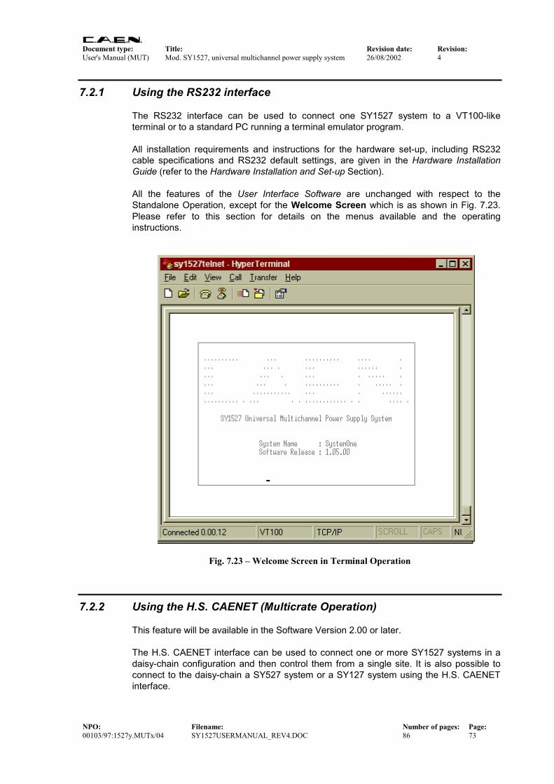
Document type: Title: Revision date: Revision: User's Manual (MUT) Mod. SY1527, universal multichannel power supply system 26/08/2002 4
NPO: Filename: Number of pages: Page: 00103/97:1527y.MUTx/04 SY1527USERMANUAL_REV4.DOC 86 73
7.2.1 Using the RS232 interface The RS232 interface can be used to connect one SY1527 system to a VT100-like terminal or to a standard PC running a terminal emulator program. All installation requirements and instructions for the hardware set-up, including RS232 cable specifications and RS232 default settings, are given in the Hardware Installation Guide (refer to the Hardware Installation and Set-up Section). All the features of the User Interface Software are unchanged with respect to the Standalone Operation, except for the Welcome Screen which is as shown in Fig. 7.23. Please refer to this section for details on the menus available and the operating instructions.
Fig. 7.23 – Welcome Screen in Terminal Operation
7.2.2 Using the H.S. CAENET (Multicrate Operation) This feature will be available in the Software Version 2.00 or later. The H.S. CAENET interface can be used to connect one or more SY1527 systems in a daisy-chain configuration and then control them from a single site. It is also possible to connect to the daisy-chain a SY527 system or a SY127 system using the H.S. CAENET interface.

Document type: Title: Revision date: Revision: User's Manual (MUT) Mod. SY1527, universal multichannel power supply system 26/08/2002 4
NPO: Filename: Number of pages: Page: 00103/97:1527y.MUTx/04 SY1527USERMANUAL_REV4.DOC 86 74
The control of the chain can be performed in the following ways:
• with a SY1527 system operating in standalone configuration or in terminal operation via RS232 or Telnet;
• with a SY527 system connected to a VT100-like terminal via the commands specific of the SY527 system; actually, if an external VT100 is connected to the SY527 system, the usual SY1527 Software User Interface will be displayed.
• with a SY127 system equipped with a A128HS board and connected to a VT100-like terminal via the commands specific of the SY127 system; actually, if an external VT100 is connected to the SY527 system, the usual SY1527 Software User Interface will be displayed.
All the features of the User Interface Software are unchanged with respect to the Standalone Operation, except for the Welcome Screen which is as shown in Fig. 7.23. Please refer to the Standalone Operation section for details on the menus available and the operating instructions.
7.2.2.1 H.S. CAENET protocol The H. S. CAENET is based on a send and receive half duplex protocol. It allows asynchronous serial transmission (1 MBaud rate) of data packets along a simple 50 Ω coaxial cable. Several devices (H. S. CAENET nodes) are able to share the same media to transmit and receive data. Each node is able to receive the serial data packet, to store it automatically in a FIFO (RX FIFO) and transmit the data contained in another FIFO (TX FIFO). Both FIFOs are 512-byte deep. Usually, the transfers between H. S. CAENET nodes take place according to the typical Master/Slaves communication. This means that:
• there is a single Master (the H. S. CAENET Controller);
• the Slaves are daisy-chained on the network, and are identified by an address code (Crate Number);
• the H. S. CAENET Master starts the transmission, all the Slaves receive the data and only the addressed Slave accesses the serial line to transmit the data requested by the Master;
• the maximum data packet length is 512 bytes.
7.2.2.2 H.S. CAENET node address The address of the H. S. CAENET node (Crate Number) is selectable via software (Connect command), and its value ranges from 0 to 99. In this way up to 100 crates may be controlled from a single system.
7.2.2.3 H.S. CAENET network termination In order to avoid reflections it is necessary to terminate the H. S. CAENET line on a 50 Ω impedance. This is accomplished as follows:
• If the H.S. CAENET Controller is one of the crates, insert a 50 Ω impedance terminator in one of the two 00 type LEMO connectors (CAENET) in the last and in the first crate of the chain.
• If the H.S. CAENET Controller is a standard PC equipped with the A303 H. S. CAENET IBM/PC Controller, insert a 50 Ω impedance terminator in one of the two 00 type LEMO connectors (CAENET) of the last crate of the chain.

Document type: Title: Revision date: Revision: User's Manual (MUT) Mod. SY1527, universal multichannel power supply system 26/08/2002 4
NPO: Filename: Number of pages: Page: 00103/97:1527y.MUTx/04 SY1527USERMANUAL_REV4.DOC 86 75
7.2.2.4 H.S. CAENET multicrate operation sequence In order to operate in multicrate operation, follow these steps:
1. set a different crate number (from 0 to 99) for each system belonging to the chain;
2. if the chain is controlled from a SY527 or a SY127 system connected to an external terminal, follow the procedure explained in the relevant manuals for multicrate operation;
3. if the chain is controlled from a SY1527 in standalone operation or in terminal operation, enter the Main menu Connect command and then type the crate number of the system of the chain you want to connect to;
4. at this point the screen of the relevant system (i.e. the system with the crate number you have typed) will be displayed directly on the screen of the system acting as controller (MASTER) allowing for the remote control of the other system.
7.2.3 Using the TCP/IP protocol via Ethernet (Telnet Client) The Ethernet interface can be used to connect one SY1527 system to a standard PC running a terminal emulator program (Telnet Client). All installation requirements and instructions for the hardware set-up, including cable specifications and TCP/IP default settings, are given in the Hardware Installation Guide (refer to the Hardware Installation and Set-up Section). Refer also to § 6.2, p.38 of this guide for TCP/IP software configuration. All the features of the User Interface Software are unchanged with respect to the Standalone Operation, except for the Welcome Screen which is as shown in Fig. 7.23. Please refer to the Standalone Operation section for details on the menus available and the operating instructions. To operate via TCP/IP protocol, follow this procedure (the example refers to Telnet Client in Win'95; Telnet Clients are available in almost all operating systems):
1. Check if the system is connected via the Ethernet interface and if the TCP/IP protocol is configured correctly;
2. Run Telnet Client software;
3. Type the Host name of the system you want connect to;
4. Type the Port: 1527;
5. Type the Terminal type: VT100;
6. Select Connect and press ENTER. At this point you are connected to the SY1527 system via Telnet protocol.

Document type: Title: Revision date: Revision: User's Manual (MUT) Mod. SY1527, universal multichannel power supply system 26/08/2002 4
NPO: Filename: Number of pages: Page: 00103/97:1527y.MUTx/04 SY1527USERMANUAL_REV4.DOC 86 76
7.3 Remote operation via Host Computer A newly released suite of applications guarantees CAEN power supplies' interoperability between virtually all available computing environments and communication protocols (TCP/IP, CANbus ...). In the latest years OPC (OLE for Process Control) has clearly emerged as one of the most popular standards in the world of industry automation. OPC is an open interface based on the OLE/COM (now ActiveX) and DCOM technology; OPC offers "Plug&Play" connectivity between disparate control applications and hardware devices. The introduction of the OPC interface has caused the number of driver developments which hardware manufacturers implement for their components to be reduced to only one: the OPC server. On the other hand, OPC client applications (from any vendor) can communicate with the OPC server to exchange data and control commands in a standard way. Each device property is accessed via an OPC item. An OPC server creates OPC items on behalf of an OPC client. The client's OPC items are organized in OPC groups with a hierarchical structure.
RS232
Standard PCrunning a custom-developed program
TCP/IP protocol via Ethernet
+ +
Computer connected to a TCP/IP Network (INTERNET/INTRANET) and running a custom-developed program
SY1527 crate
1 2 3
44 5 6
7 8 9. 0 -
CMD DEL ACK
CANBUS
Computer connected to a CANBUSnetwork and running
a custom-developed program
Fig. 7.24 – Remote Operation via Host Computer
CAEN, in close collaboration with CERN (IT-CO group) has developed an OPC server which allows powerful, flexible and yet simple control of its power supply systems, indifferently through TCP/IP, RS232 or H.S. CAENET communication path by any OPC compliant client application. For further details please refer to the OPC Server for CAEN Power Supplies User’s Manual available from http://www.caen.it/computing.

Document type: Title: Revision date: Revision: User's Manual (MUT) Mod. SY1527, universal multichannel power supply system 26/08/2002 4
NPO: Filename: Number of pages: Page: 00103/97:1527y.MUTx/04 SY1527USERMANUAL_REV4.DOC 86 77
Moreover an ActiveX object library (activeHV) is now available, enabling CAEN power supplies to be controlled by and exchange data with a variety of Windows applications supporting the ActiveX standard, including Visual Basic, Visual C++, Internet Explorer and MS office programs. For further details please refer to the ActiveHV Object Library Documentation available from http://www.caen.it/computing.
Fig. 7.25 – Software architecture
As illustrated in Fig. 7.25 , both OPC Server and ActiveHV control are on the 3th level of a layered software structure in which the 1st level is represented by the communication drivers and libraries (for TCP/IP or CAENET) and the 2nd level is the library called CAENHVWrapper, which exports a set of routines permitting the control of a generic CAEN Power Supply System.

Document type: Title: Revision date: Revision: User's Manual (MUT) Mod. SY1527, universal multichannel power supply system 26/08/2002 4
NPO: Filename: Number of pages: Page: 00103/97:1527y.MUTx/04 SY1527USERMANUAL_REV4.DOC 86 78
8. Trip handling If a channel trips (see § 2.2 for details about the Trip) due to Over Current, it can be useful to have the possibility of letting automatically other channels (which are not in Over Current) trip; this feature is implemented on most of the SY1527 PS boards.
8.1 Internal Trip A PS Board features a number of “virtual” trip lines usually equal to half the number of its channels, so a 12 channel board features an internal 6-line Trip Bus. The channels communicate with each other through this bus: a channel can be allowed to either propagate or sense (or both propagate and sense) the trip status through one or more trip lines. This feature is achieved by writing a 2N-bit word (Dec. 0÷22N-1) in the relevant channel’s TRIPINT parameter, where N is the number of the board’s Internal Trip Bus lines. Bits [0;N-1] allow the channel to sense the trip status from the corrisponding lines when set to one; in the same way, bits [N;2N-1] allow the channel to propagate the trip status over the Trip Bus: bit N on line 0 and so on. For example we consider a 12 channel board with a 6-line trip bus (TRIPINT[n]: 0÷4095): if TRIPINT[0] is set to 64 (CH0 propagates the TRIP on line 0), TRIPINT[3] is set to 65, TRIPINT[4] is set to 65 (CH3 and CH4 both propagate and sense the TRIP on line 0) and TRIPINT[5] is set to 1 (CH5 senses the TRIP on line 0), then:
- CH3 trips whenever either CH0 or CH4 trips - CH4 trips whenever either CH0 or CH3 trips - CH5 trips whenever either CH0 or CH3 trips or CH4 trips
This configuration is shown in Fig. 8.1.

Document type: Title: Revision date: Revision: User's Manual (MUT) Mod. SY1527, universal multichannel power supply system 26/08/2002 4
NPO: Filename: Number of pages: Page: 00103/97:1527y.MUTx/04 SY1527USERMANUAL_REV4.DOC 86 79
Fig. 8.1 – Trip Bus scheme
8.2 External Trip The External Trip shares most of its features with the internal one. The number of lines is four, fixed for any kind of board, so the TRIPEXT parameter must be set in the 0÷255 range. Bits [0;3] allow the channel to sense the trip status from the corrisponding lines when set to one; in the same way, bits [4;7] allow the channel to propagate the trip status over the trip bus: bit 4 on line 0 and so on. Moreover SY1527 front panel I/O connectors allow the bus control. A logic level sent to a line of the External Trip input allows to propagate the trip status over the relevant line as well as the External Trip outputs allow to monitor the bus status.
PROPAGATE SENSE
TRIPINT0
TRIPINT4
TRIPINT5
TRIPINT6
LIN
E 2
LIN
E 3
LIN
E 4
LIN
E 5
LIN
E 0
LIN
E 1
LIN
E 2
LIN
E 3
TRIPINT2
TRIPINT3
TRIPINT1
0 0 0 1 0 0 0 0
0 0 0 0 0 0 0 0
0 0 0 0 0 0 0 0
0 0 0 1 0 0 0 0
0 0 0 0 0 0 0 0
0 0 0 1 0 0 0 0
0 0 0 0 0 0 0 0
0 0 0 0 0 0 0 0
0 0 0 0 0 0 0 0
0 0 0 0 0 0 0 0
0 0 0 0 0 0 0 0
0 0 0 0 0 0 0 0
LIN
E 4
LIN
E 5
0 0
0 0
0 0
0 0
0 0
0 0
0 0
0 0
0 0
0 0
0 0
0 0
LIN
E 0
LIN
E 1
0 0
0 0
0 0
0 1
0 1
0 1
0 0
0 0
0 0
0 0
0 0
0 0
TRIPINT7
TRIPINT11
TRIPINT9
TRIPINT10
TRIPINT8
9 8 7 6 5 4 3 211 10 1 0bit
INTERNAL TRIP BUS

Document type: Title: Revision date: Revision: User's Manual (MUT) Mod. SY1527, universal multichannel power supply system 26/08/2002 4
NPO: Filename: Number of pages: Page: 00103/97:1527y.MUTx/04 SY1527USERMANUAL_REV4.DOC 86 80
9. Error handling This feature will be available in the Software Version 2.00 or later.

Document type: Title: Revision date: Revision: User's Manual (MUT) Mod. SY1527, universal multichannel power supply system 26/08/2002 4
NPO: Filename: Number of pages: Page: 00103/97:1527y.MUTx/04 SY1527USERMANUAL_REV4.DOC 86 81
10. Secure access and User’s profile management
10.1 Multilevel login profile environment The SY1527 User Software Interface allows for a multilevel management of user’s login profiles in order to protect the system from improper use. This feature provides three different login levels: Guest, User and Administrator, each with a different level of access ability to the menus concerning parameter monitoring and setting. All login profiles are protected by access passwords. The lowest access level is represented by the Guest profile: a user who is logged as Guest, will be able only to monitor system and channel parameters. The standard access level is represented by the User profile: a user who is logged as User can monitor and set channel parameters but is not allowed to change interface settings and system parameters and to control login profiles. The highest access level is reserved to the Administrator profile, which is allowed to set any kind of channel and system parameter, to change interface settings and to manage the various login profiles. A list of the operations which can be performed by the three different types of login profiles is reported in
Document type: Title: Revision date: Revision: User's Manual (MUT) Mod. SY1527, universal multichannel power supply system 26/08/2002 4
NPO: Filename: Number of pages: Page: 00103/97:1527y.MUTx/04 SY1527USERMANUAL_REV4.DOC 87 82
Table 10.1.

Document type: Title: Revision date: Revision: User's Manual (MUT) Mod. SY1527, universal multichannel power supply system 26/08/2002 4
NPO: Filename: Number of pages: Page: 00103/97:1527y.MUTx/04 SY1527USERMANUAL_REV4.DOC 87 83
Table 10.1 – Operations allowed in a Guest, User and Administrator login session
Type of operation Guest session
User session
Admin. session
Channel parameter monitoring
Channel parameter setting
System control in daisy-chain configuration
Crate mapping
Kill via software
Clear alarm
General status (GEN LED) definition
Flash Memory Format
Firmware upgrading
Reset Flag conditions
Communication settings
HV clock configuration
Group monitoring (Group mode toggle command)
Group setting
Trip handling
Error handling
Customising user environment
Multilevel Login Profile management
NOTICE!
PRESENTLY, THE GUEST PROFILE AND THE USER PROFILE
HAVE THE SAME TYPE OF ACCESS LEVEL (User Access Level)!
Moreover, password protection for each channel or group of channels is also foreseen as well as the possibility of defining preferred custom environments for each single user. For details on this last feature please refer to § 7.1.14, p.59.

Document type: Title: Revision date: Revision: User's Manual (MUT) Mod. SY1527, universal multichannel power supply system 26/08/2002 4
NPO: Filename: Number of pages: Page: 00103/97:1527y.MUTx/04 SY1527USERMANUAL_REV4.DOC 87 84
10.1.1 Guest profile Presently, the only usernames and relevant passwords accepted by the software as Guest Profile are: Username Password
guest guest
1527 1527 N.B.: please note that username and password typing is case sensitive!
10.1.2 User profile Presently, the only username and relevant password accepted by the software as User Profile is: Username Password
user user N.B.: please note that username and password typing is case sensitive!
10.1.3 Administrator profile Presently, the only username and relevant password accepted by the software as Administrator Profile is: Username Password
admin admin N.B.: please note that username and password typing is case sensitive!
10.2 General settings for password protection This feature will be available in the Software Version 2.00 or later.
10.3 Assigning a login profile This feature will be available in the Software Version 2.00 or later.
10.4 Customising the environment This feature will be available in the Software Version 2.00 or later.

Document type: Title: Revision date: Revision: User's Manual (MUT) Mod. SY1527, universal multichannel power supply system 26/08/2002 4
NPO: Filename: Number of pages: Page: 00103/97:1527y.MUTx/04 SY1527USERMANUAL_REV4.DOC 87 85
11. System Diagnostic procedures Presently, the only automatic diagnostic procedure available is shown in the Tech Info pop-up window accessible from the Set Up menu (see § 7.1.26, p.70). Further diagnostic procedures will be available in the Software Version 2.00 or later.

Document type: Title: Revision date: Revision: User's Manual (MUT) Mod. SY1527, universal multichannel power supply system 26/08/2002 4
NPO: Filename: Number of pages: Page: 00103/97:1527y.MUTx/04 SY1527USERMANUAL_REV4.DOC 87 86
APPENDIX A

Document type: Title: Revision date: Revision: User's Manual (MUT) Mod. SY1527, universal multichannel power supply system 26/08/2002 4
NPO: Filename: Number of pages: Page: 00103/97:1527y.MUTx/04 SY1527USERMANUAL_REV4.DOC 87 87
SY1527 system Front Panel