User’s Manual UM33A Digital Indicator with Alarms User’s...
166
User’s Manual UM33A Digital Indicator with Alarms User’s Manual IM 05P03D21-01EN IM 05P03D21-01EN 2nd Edition
Transcript of User’s Manual UM33A Digital Indicator with Alarms User’s...
User’sManual UM33A
Digital Indicator with AlarmsUser’s Manual
IM 05P03D21-01EN
IM 05P03D21-01EN2nd Edition

Product RegistrationThank you for purchasing YOKOGAWA products.
YOKOGAWA provides registered users with a variety of information and services.Please allow us to serve you best by completing the product registration form accessible from our homepage.
http://www.yokogawa.com/ns/reg/

iIM 05P03D21-01EN
2nd Edition : Jan. 2011 (YK)All Rights Reserved, Copyright © 2010-2011 Yokogawa Electric Corporation
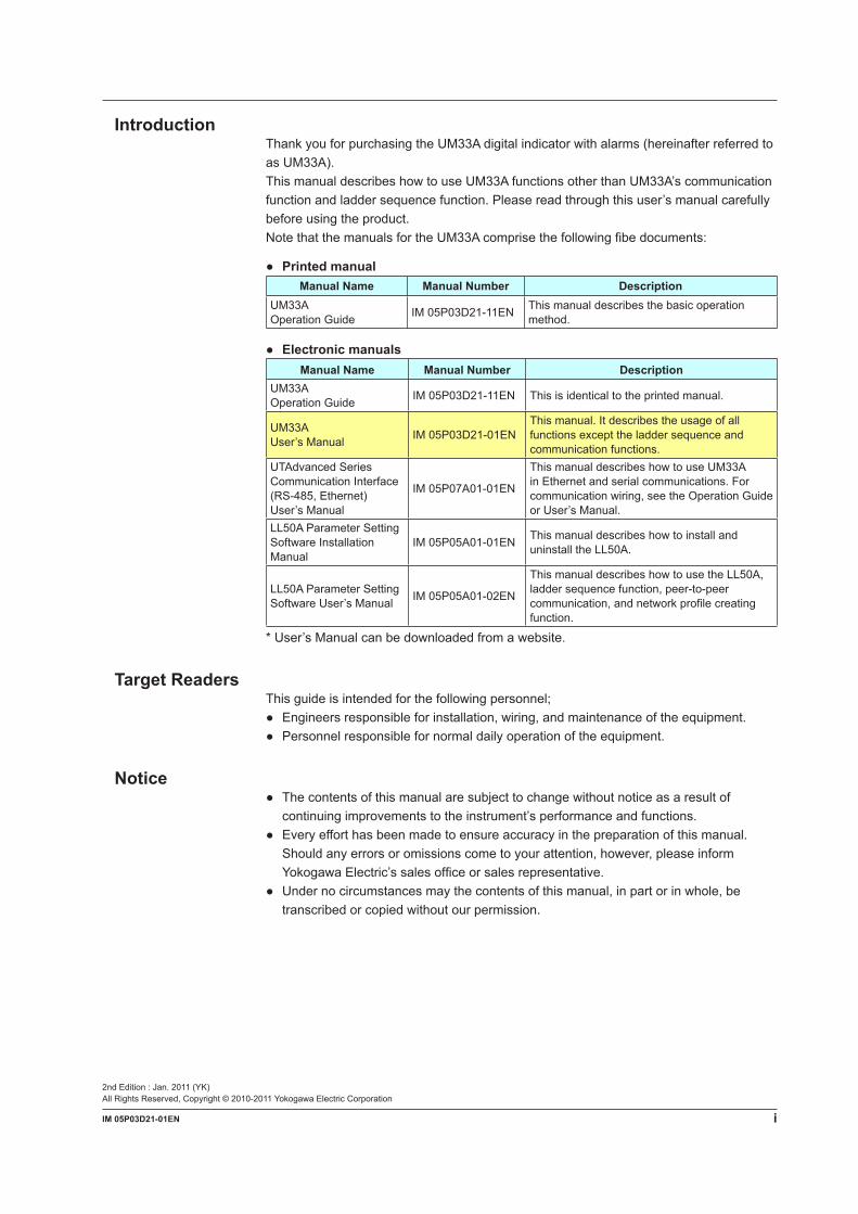
IntroductionThank you for purchasing the UM33A digital indicator with alarms (hereinafter referred to as UM33A).This manual describes how to use UM33A functions other than UM33A’s communication function and ladder sequence function. Please read through this user’s manual carefully before using the product.Note that the manuals for the UM33A comprise the following fibe documents:
PrintedmanualManual Name Manual Number Description
UM33AOperation Guide IM 05P03D21-11EN This manual describes the basic operation
method.
ElectronicmanualsManual Name Manual Number Description
UM33AOperation Guide IM 05P03D21-11EN This is identical to the printed manual.
UM33A User’s Manual IM 05P03D21-01EN
This manual. It describes the usage of all functions except the ladder sequence and communication functions.
UTAdvanced Series Communication Interface (RS-485, Ethernet) User’s Manual
IM 05P07A01-01EN
This manual describes how to use UM33A in Ethernet and serial communications. For communication wiring, see the Operation Guide or User’s Manual.
LL50A Parameter Setting Software Installation Manual
IM 05P05A01-01EN This manual describes how to install and uninstall the LL50A.
LL50A Parameter Setting Software User’s Manual IM 05P05A01-02EN
This manual describes how to use the LL50A, ladder sequence function, peer-to-peer communication, and network profile creating function.
* User’s Manual can be downloaded from a website.
Target ReadersThis guide is intended for the following personnel; Engineersresponsibleforinstallation,wiring,andmaintenanceoftheequipment. Personnelresponsiblefornormaldailyoperationoftheequipment.
Notice Thecontentsofthismanualaresubjecttochangewithoutnoticeasaresultof
continuing improvements to the instrument’s performance and functions. Everyefforthasbeenmadetoensureaccuracyinthepreparationofthismanual.
Should any errors or omissions come to your attention, however, please inform YokogawaElectric’ssalesofficeorsalesrepresentative.
Undernocircumstancesmaythecontentsofthismanual,inpartorinwhole,betranscribed or copied without our permission.
ii IM 05P03D21-01EN
Trademarks Ourproductnamesorbrandnamesmentionedinthismanualarethetrademarksor
registered trademarks of Yokogawa Electric Corporation (hereinafter referred to as YOKOGAWA).
Microsoft,MS-DOS,Windows,WindowsXP,WindowsVista,andWindows7areeither registered trademarks or trademarks of Microsoft Corporation in the United States and/or other countries.
Adobe,Acrobat,andPostscriptareeitherregisteredtrademarksortrademarksofAdobe Systems Incorporated.
EthernetisaregisteredtrademarkofXEROXCorporationintheUnitedStates. ModbusisaregisteredtrademarkofSchneiderElectric. WedonotusetheTMor®marktoindicatethesetrademarksorregistered
trademarks in this user’s manual. Allotherproductnamesmentionedinthisuser’smanualaretrademarksorregistered
trademarks of their respective companies.
Safety PrecautionsThis instrument is a product of Installation Category II of IEC/EN/CSA/UL61010-1 Safety Standards and Class A of EN61326-1, EN55011 (EMC Standards).
CAUTIONThis instrument is an EMC class A product. In a domestic environment, this product may cause radio interference in which case the user needs to take adequate measures.
The instrument is a product rated Measurement Category I (CAT.I). * Measurement Category I (CAT.I) This category applies to electric equipment that measures a circuit connected to a
low-voltage facility and receives power from stationary equipment such as electric switchboards.
To use the instrument properly and safely, observe the safety precautions described in this user’s manual when operating it. Use of the instrument in a manner not prescribed herein may compromise protection features inherent in the device. We assume no liability for or warranty on a fault caused by users’ failure to observe these instructions.This instrument is designed to be used within the scope of Measurement Category I (CAT.I) and is dedicated for indoor use.
Notes on the User’s Manual• This user’s manual should be readily accessible to the end users so it can be referred
to easily. It should be kept in a safe place.• Read the information contained in this manual thoroughly before operating the
product.• The purpose of this user’s manual is not to warrant that the product is well suited to
any particular purpose, but rather to describe the functional details of the product.
iiiIM 05P03D21-01EN
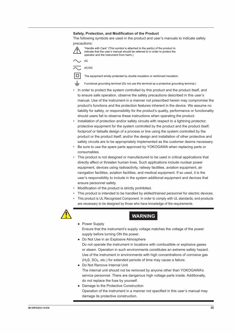
Safety, Protection, and Modification of the ProductThe following symbols are used in the product and user’s manuals to indicate safety precautions:
AC
AC/DC
“Handle with Care” (This symbol is attached to the part(s) of the product to indicate that the user’s manual should be referred to in order to protect the operator and the instrument from harm.)
The equipment wholly protected by double insulation or reinforced insulation.
Functional grounding terminal (Do not use this terminal as a protective grounding terminal.)
• In order to protect the system controlled by this product and the product itself, and to ensure safe operation, observe the safety precautions described in this user’s manual. Use of the instrument in a manner not prescribed herein may compromise the product’s functions and the protection features inherent in the device. We assume no liability for safety, or responsibility for the product’s quality, performance or functionality should users fail to observe these instructions when operating the product.
• Installation of protection and/or safety circuits with respect to a lightning protector; protective equipment for the system controlled by the product and the product itself; foolproof or failsafe design of a process or line using the system controlled by the product or the product itself; and/or the design and installation of other protective and safety circuits are to be appropriately implemented as the customer deems necessary.
• Be sure to use the spare parts approved by YOKOGAWA when replacing parts or consumables.
• This product is not designed or manufactured to be used in critical applications that directly affect or threaten human lives. Such applications include nuclear power equipment, devices using radioactivity, railway facilities, aviation equipment, air navigation facilities, aviation facilities, and medical equipment. If so used, it is the user’s responsibility to include in the system additional equipment and devices that ensure personnel safety.
• Modificationoftheproductisstrictlyprohibited.• This product is intended to be handled by skilled/trained personnel for electric devices.• This product is UL Recognized Component. In order to comply with UL standards, end-products
are necessary to be designed by those who have knowledge of the requirements.
WARNING PowerSupply Ensure that the instrument’s supply voltage matches the voltage of the power
supply before turning ON the power. DoNotUseinanExplosiveAtmosphere Do not operate the instrument in locations with combustible or explosive gases
or steam. Operation in such environments constitutes an extreme safety hazard. Use of the instrument in environments with high concentrations of corrosive gas (H2S, SOX, etc.) for extended periods of time may cause a failure.
DoNotRemoveInternalUnit The internal unit should not be removed by anyone other than YOKOGAWA’s
service personnel. There are dangerous high voltage parts inside. Additionally, do not replace the fuse by yourself.
DamagetotheProtectiveConstruction Operation of the instrument in a manner not specified in this user’s manual may
damage its protective construction.
iv IM 05P03D21-01EN
Warning and Disclaimer• YOKOGAWA makes no warranties regarding the product except those stated in the
WARRANTY that is provided separately.• The product is provided on an “as is” basis. YOKOGAWA assumes no liability to any
person or entity for any loss or damage, direct or indirect, arising from the use of the product or from any unpredictable defect of the product.
Notes on Software• YOKOGAWA makes no warranties, either expressed or implied, with respect to the
software’smerchantabilityorsuitabilityforanyparticularpurpose,exceptasspecifiedin the terms of the separately provided warranty.
• Thissoftwaremaybeusedononespecificmachineonly.• To use the software on another machine, the software must be purchased again
separately.• It is strictly prohibited to reproduce the product except for backup purposes.• Store the software CD-ROM (the original medium) in a safe place.• All reverse-engineering operations, such as reverse compilation or the reverse
assembly of the product are strictly prohibited.• No part of the product’s software may be transferred, converted, or sublet for use by
any third party, without prior written consent from YOKOGAWA.
Handling Precautions for the Main Unit• The instrument comprises many plastic components. To clean it, wipe it with a soft,
dry cloth. Do not use organic solvents such as benzene or thinner for cleaning, as discoloration or deformation may result.
• Keepelectricallychargedobjectsawayfromthesignalterminals.Notdoingsomaycause the instrument to fail.
• Do not apply volatile chemicals to the display area, operation keys, etc. Do not leave theinstrumentincontactwithrubberorPVCproductsforextendedperiods.Doingsomay result in failure.
• If the equipment emits smoke or abnormal smells or makes unusual noises, turn OFF the instrument’s power immediately and unplug the device. In such an event, contact your sales representative.
Waste Electrical and Electronic Equipment (WEEE), Directive 2002/96/ECThis is an explanation of how to dispose of this product based on Waste Electrical and Electronic Equipment (WEEE), Directive 2002/96/EC. This directive is only valid in the EU.
MarkingThis product complies with the WEEE Directive (2002/96/EC) marking requirement.This marking indicates that you must not discard this electrical/electronic product in domestic household waste.
Product CategoryWith reference to the equipment types in the WEEE directive Annex 1, this product is classified as a “Monitoring and Control instrumentation” product.Do not dispose in domestic household waste. When disposing products in the EU, contactyourlocalYokogawaEuropeB.V.office.
vIM 05P03D21-01EN
Checking the Contents of the PackageUnpack the box and check the contents before using the product. If the product is different from that which you have ordered, if any parts or accessories are missing, or if the product appears to be damaged, contact your sales representative.
UM33A Main UnitThe UM33A main units have nameplates affixed to the side of the case.Check the model and suffix codes inscribed on the nameplate to confirm that the product received is that which was ordered.
No. (Instrument number)When contacting your sales representative, inform them of this number, too.
NoteThe last digit of the display code (-x0) has been changed into the case color code.
vi IM 05P03D21-01EN
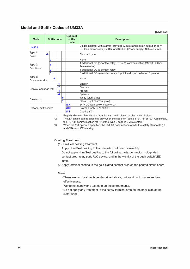
Model and Suffix Codes of UM33A[Style:S2]
Model Suffix codeOptional
suffix code
Description
UM33A DigitalIndicatorwithAlarms(providedwithretransmissionoutputor15VDClooppowersupply,2DIs,and3DOs)(Powersupply:100-240VAC)
Type 1: Basic
-0 Standard type
Type 2:Functions
0 None
1 1 additional DO (c-contact relay), RS-485 communication (Max.38.4 kbps, 2-wire/4-wire)
2 1 additional DO (c-contact relay)3 6 additional DOs (c-contact relay; 1 point and open collector; 5 points)
Type 3:Open networks
0 None
Display language (*1)
-1 English-2 German-3 French-4 Spanish
Case color0 White (Light gray)1 Black (Light charcoal gray)
Optional suffix codes/LP 24VDClooppowersupply(*2)/DC Powersupply24VAC/DC/CT Coating (*3)
*1: English, German, French, and Spanish can be displayed as the guide display.*2: The /LP option can be specified only when the code for Type 2 is "0", "1" or "2." Additionally,
the RS-485 communication for “1” of the Type 2 code is 2-wire system.*3: When the /CT option is specified, the UM33A does not conform to the safety standards (UL
and CSA) and CE marking.
Coating Treatment(1) HumiSeal coating treatment Apply HumiSeal coating to the printed circuit board assembly. Do not apply HumiSeal coating to the following parts: connector, gold-plated
contact area, relay part, RJC device, and in the vicinity of the push switch/LED lamp.
(2) Apply terminal coating to the gold-plated contact area on the printed circuit board.
Notes Therearetwotreatmentsasdescribedabove,butwedonotguaranteetheir
effectiveness. We do not supply any test data on these treatments. Donotapplyanytreatmenttothescrewterminalareaonthebacksideofthe
instrument.
viiIM 05P03D21-01EN
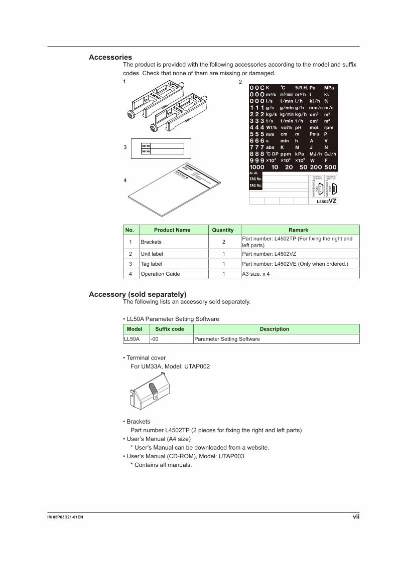
AccessoriesThe product is provided with the following accessories according to the model and suffix codes. Check that none of them are missing or damaged.
1 2
4
3
No. Product Name Quantity Remark
1 Brackets 2 Part number: L4502TP (For fixing the right and left parts)
2 Unit label 1 Partnumber:L4502VZ
3 Tag label 1 Partnumber:L4502VE(Onlywhenordered.)
4 Operation Guide 1 A3 size, x 4
Accessory (sold separately)The following lists an accessory sold separately.
• LL50A Parameter Setting SoftwareModel Suffix code Description
LL50A -00 Parameter Setting Software
• Terminal cover For UM33A, Model: UTAP002
• Brackets Part number L4502TP (2 pieces for fixing the right and left parts)• User’s Manual (A4 size) * User’s Manual can be downloaded from a website.• User’s Manual (CD-ROM), Model: UTAP003 * Contains all manuals.
viii IM 05P03D21-01EN
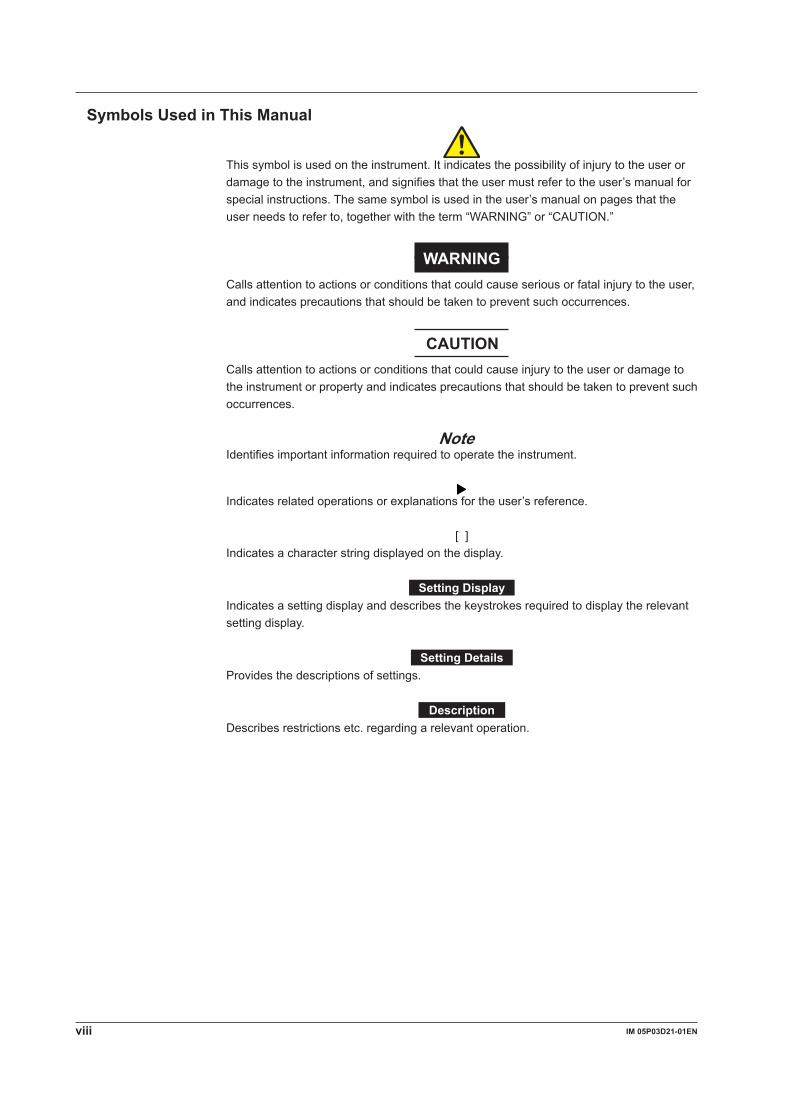
Symbols Used in This Manual
Thissymbolisusedontheinstrument.Itindicatesthepossibilityofinjurytotheuserordamage to the instrument, and signifies that the user must refer to the user’s manual for special instructions. The same symbol is used in the user’s manual on pages that the user needs to refer to, together with the term “WARNING” or “CAUTION.”
WARNINGCallsattentiontoactionsorconditionsthatcouldcauseseriousorfatalinjurytotheuser,and indicates precautions that should be taken to prevent such occurrences.
CAUTIONCallsattentiontoactionsorconditionsthatcouldcauseinjurytotheuserordamagetothe instrument or property and indicates precautions that should be taken to prevent such occurrences.
NoteIdentifies important information required to operate the instrument.
Indicates related operations or explanations for the user’s reference.
[ ]Indicates a character string displayed on the display.
Setting DisplayIndicates a setting display and describes the keystrokes required to display the relevant setting display.
Setting DetailsProvides the descriptions of settings.
DescriptionDescribes restrictions etc. regarding a relevant operation.
ixIM 05P03D21-01EN ix
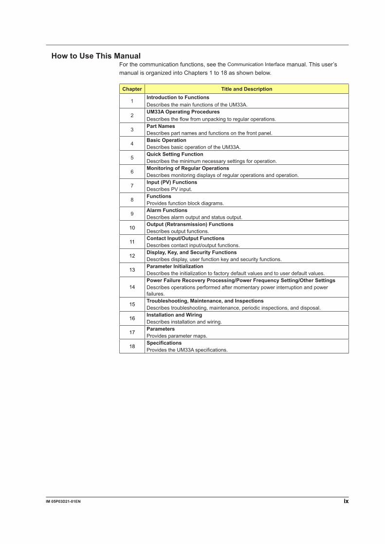
How to Use This ManualFor the communication functions, see the Communication Interface manual. This user’s manual is organized into Chapters 1 to 18 as shown below.
Chapter Title and Description
1Introduction to FunctionsDescribes the main functions of the UM33A.
2UM33A Operating ProceduresDescribes the flow from unpacking to regular operations.
3Part NamesDescribes part names and functions on the front panel.
4Basic OperationDescribes basic operation of the UM33A.
5Quick Setting FunctionDescribes the minimum necessary settings for operation.
6Monitoring of Regular OperationsDescribes monitoring displays of regular operations and operation.
7Input (PV) FunctionsDescribesPVinput.
8FunctionsProvides function block diagrams.
9Alarm FunctionsDescribes alarm output and status output.
10Output (Retransmission) FunctionsDescribes output functions.
11Contact Input/Output FunctionsDescribes contact input/output functions.
12Display, Key, and Security FunctionsDescribes display, user function key and security functions.
13Parameter InitializationDescribes the initialization to factory default values and to user default values.
14Power Failure Recovery Processing/Power Frequency Setting/Other SettingsDescribes operations performed after momentary power interruption and power failures.
15Troubleshooting, Maintenance, and InspectionsDescribes troubleshooting, maintenance, periodic inspections, and disposal.
16Installation and WiringDescribes installation and wiring.
17ParametersProvides parameter maps.
18SpecificationsProvides the UM33A specifications.

Blank Page
xiIM 05P03D21-01EN
1
2
3
4
5
6
7
8
9
10
11
12
13
14
15
16
17
18
App
App
Index
Contents
Introduction ............................................................................................................................iTarget Readers ......................................................................................................................iNotice ................................................................................................................................iTrademarks .......................................................................................................................... iiSafety Precautions ............................................................................................................... iiHandling Precautions for the Main Unit ............................................................................... ivWaste Electrical and Electronic Equipment (WEEE), Directive 2002/96/EC ....................... ivChecking the Contents of the Package ................................................................................vModel and Suffix Codes of UM33A......................................................................................viSymbols Used in This Manual ........................................................................................... viiiHow to Use This Manual ..................................................................................................... ix
Chapter 1 Introduction to Functions1.1 Quick Setting Function ..................................................................................................... 1-11.2 Input/Output Function ....................................................................................................... 1-21.3 Display and Key Functions ............................................................................................... 1-41.4 Communication Functions ................................................................................................ 1-51.5 Definition of Main Symbols and Terms ............................................................................. 1-7
Chapter 2 UM33A Operating Procedures2.1 UM33A Operating Procedures ......................................................................................... 2-1
Chapter 3 Part Names3.1 Names and Functions of Display Parts ............................................................................ 3-13.2 Names and Functions of Keys ......................................................................................... 3-23.3 List of Display Symbols .................................................................................................... 3-43.4 Brief Description of Setting Details (Parameters) ............................................................. 3-6
Chapter 4 Basic Operation4.1 Overview of Display Switch and Operation Keys ............................................................. 4-14.2 How to Set Parameters .................................................................................................... 4-4
Chapter 5 Quick Setting Function5.1 Setting Using Quick Setting Function ............................................................................... 5-15.2 Restarting Quick Setting Function .................................................................................... 5-6
Chapter 6 Monitoring of Regular Operations6.1 Monitoring of Operation Displays ..................................................................................... 6-1
6.1.1 Operation Display Transitions ............................................................................. 6-16.2 Setting Alarm Setpoint ...................................................................................................... 6-36.3 Releasing On-State (Latch) of Alarm Output .................................................................... 6-46.4 ConfirmationofPVpeakandbottomvalue ...................................................................... 6-5
Chapter 7 Input (PV) Functions7.1 SettingFunctionsofPVInput ........................................................................................... 7-1
7.1.1 Setting Input Type, Unit, Range, Scale, and Decimal Point Position .................. 7-17.1.2 Setting Burnout Detection for Input ..................................................................... 7-47.1.3 Setting Reference Junction Compensation (RJC) or External Reference
Junction Compensation (ERJC) ......................................................................... 7-5
xii IM 05P03D21-01EN
7.1.4 CorrectingInputValue ........................................................................................ 7-6(1) Setting Bias and Filter ....................................................................................................7-6(2) Setting Square Root Extraction and Low Signal Cutoff Point .........................................7-7(3) Setting 10-segment Linearizer ........................................................................................7-8
7.2 Setting Input Sampling Period ........................................................................................ 7-10
Chapter 8 Functions8.1 Function Block Diagrams ................................................................................................. 8-1
Chapter 9 Alarm Functions9.1 Setting Alarm Type ........................................................................................................... 9-19.2 Setting Number of Alarm Groups to Use .......................................................................... 9-79.3 Setting Hysteresis to Alarm Operation ............................................................................. 9-89.4 Delaying Alarm Output (Alarm Delay Timer) .................................................................... 9-9
Chapter 10 Retransmission Output Functions10.1 Setting Retransmission Output Terminal, Type, and Scales ........................................... 10-110.2 Setting 10-segment Linearizer for Output ...................................................................... 10-210.3 Changing Current Output Range .................................................................................... 10-410.4 Setting Split Computation Output Function .................................................................... 10-510.5 Using15VDCLoopPowerSupply ............................................................................... 10-6
Chapter 11 Contact Input/Output Functions11.1 Setting Contact Input Function ........................................................................................11-1
11.1.1 Setting Contact Input Function ..........................................................................11-111.1.2 Changing Contact Type of Contact Input ...........................................................11-3
11.2 Setting Contact Output Function .....................................................................................11-411.2.1 Setting Function of Contact Output ....................................................................11-411.2.2 Changing Contact Type of Contact Output ........................................................11-7
Chapter 12 Display, Key, and Security Functions12.1 Setting Display Functions ............................................................................................... 12-1
12.1.1 SettingActiveColorPVDisplayFunction ......................................................... 12-112.1.2 MaskingArbitraryDisplayValueinOperationDisplay ...................................... 12-312.1.3 Registering SELECT Display (Up to 5 Displays) .............................................. 12-412.1.4 Changing Event Display ................................................................................... 12-512.1.5 MaskingLeastSignificantDigitofPVDisplay .................................................. 12-612.1.6 Setting Economy Mode ..................................................................................... 12-712.1.7 Selecting the Initial Operation Display that Appears at Power ON ................... 12-712.1.8 Setting Message Function ................................................................................ 12-812.1.9 Switching Guide Display Language .................................................................. 12-812.1.10 Changing Guide Scroll Speed .......................................................................... 12-912.1.11 Turning Guide Display ON/OFF ........................................................................ 12-912.1.12 Setting Automatic Return to Operation Display ................................................ 12-912.1.13 SettingBrightnessAdjustmentofLCDandDisplayUpdateCycle ................. 12-10
12.2 Assigning Function to User Function Key .....................................................................12-1112.3 Setting Security Functions ............................................................................................ 12-13
12.3.1 Setting a Password ......................................................................................... 12-1312.3.2 Setting Parameter Display Level .................................................................... 12-1312.3.3 Locking (Hiding) Parameter Menu Display ..................................................... 12-1412.3.4 Key Lock ......................................................................................................... 12-1512.3.5 Setting Display/Non-display of Operation Display .......................................... 12-1512.3.6 Prohibiting Writing via Communication ........................................................... 12-15
12.4 ConfirmationofKeyandI/OConditionandVersion ..................................................... 12-16
Contents
xiiiIM 05P03D21-01EN
1
2
3
4
5
6
7
8
9
10
11
12
13
14
15
16
17
18
App
App
Index
12.4.1 Confirmation of Key and I/O Condition ........................................................... 12-1612.4.2 ConfirmationofVersion .................................................................................. 12-18
Chapter 13 Parameter Initialization13.1 InitializingParameterSettingstoFactoryDefaultValues ............................................... 13-113.2 RegisteringandInitializingUserDefaultValues ............................................................. 13-2
13.2.1 RegisteringasUserSetting(Default)Values.................................................... 13-213.2.2 InitializingtoUserSetting(Default)Values ....................................................... 13-2
Chapter 14 Power Failure Recovery Processing / Power Frequency Setting / Other Settings14.1 Remedies if Power Failure Occurs during Operations ................................................... 14-114.2 Power Frequency Setting ............................................................................................... 14-214.3 Setting Time between Powering on Indicator and Starting Monitor (Restart Timer) ....... 14-3
Chapter 15 Troubleshooting, Maintenance, and Inspections15.1 Troubleshooting .............................................................................................................. 15-1
15.1.1 Troubleshooting Flowchart ................................................................................ 15-115.1.2 Errors at Power On ........................................................................................... 15-215.1.3 Errors during Operation .................................................................................... 15-3
15.2 Maintenance ................................................................................................................... 15-815.2.1 Cleaning ............................................................................................................ 15-815.2.2 Packaging when Shipping the Product for Repair ............................................ 15-815.2.3 Replacing Parts ................................................................................................ 15-8
15.3 Periodic Maintenance .................................................................................................... 15-915.4 Disposal ........................................................................................................................ 15-10
Chapter 16 Installation and Wiring16.1 Installation Location ........................................................................................................ 16-116.2 Mounting Method ............................................................................................................ 16-316.3 External Dimensions and Panel Cutout Dimensions ...................................................... 16-416.4 Wiring ............................................................................................................................. 16-5
16.4.1 Important Information on Wiring ....................................................................... 16-516.4.2 PVInputWiring ................................................................................................. 16-716.4.3 Contact Input Wiring ......................................................................................... 16-816.4.4 Contact Output Wiring ...................................................................................... 16-916.4.5 Retransmission Output Wiring ........................................................................16-1116.4.6 15VDCLoopPowerSupplyWiring ................................................................16-1116.4.7 24VDCLoopPowerSupplyWiring ................................................................16-1116.4.8 RS-485 Communication Interface Wiring ....................................................... 16-1216.4.9 Power Supply Wiring ...................................................................................... 16-13
16.5 Attaching and Detaching Terminal Cover ..................................................................... 16-14
Chapter 17 Parameters17.1 Parameter Map ............................................................................................................... 17-117.2 List of Parameters .......................................................................................................... 17-6
17.2.1 Operation Parameters ...................................................................................... 17-617.2.2 Setup Parameters ............................................................................................. 17-8
Chapter 18 Specifications18.1 Hardware Specifications ................................................................................................. 18-1
18.1.1 Input Specifications ........................................................................................... 18-218.1.2 Step Response Time Specifications ................................................................. 18-3
Contents
xiv IM 05P03D21-01EN
18.1.3 Relay Contact Output Specifications ................................................................ 18-318.1.4 Retransmission Output Specifications .............................................................. 18-418.1.5 15VDCLoopPowerSupplySpecifications ..................................................... 18-418.1.6 Contact Input Specifications ............................................................................. 18-418.1.7 Transistor Contact Output Specifications .......................................................... 18-418.1.8 24VDCLoopPowerSupplySpecifications ..................................................... 18-418.1.9 Safety and EMC Standards .............................................................................. 18-518.1.10 Construction, Installation, and Wiring ............................................................... 18-518.1.11 Power Supply Specifications and Isolation ...................................................... 18-618.1.12 Environmental Conditions ................................................................................. 18-7
Appendix Input and Output TableAppendix 1 Input and Output Table ..........................................................................................App-1
Revision Information
Contents

1-1IM 05P03D21-01EN
Introduction to Functions
11.1 Quick Setting Function
The Quick setting function is a function to easily set the basic function of the indicator.
Check the contents.Buy andUnpacking
Installationand Wiring
Setup
Operation
8
Installation and Wiring: Chapter 16Install and wire a indicator, and then turn on the power.
Q: What should I do to perform operateimmediately?
First, I want to set the input and output.
A: Use the Quick setting function to perform the setup easily.
Quick setting function: Chapter 5
Chapter 1 Introduction to Functions
1-2 IM 05P03D21-01EN
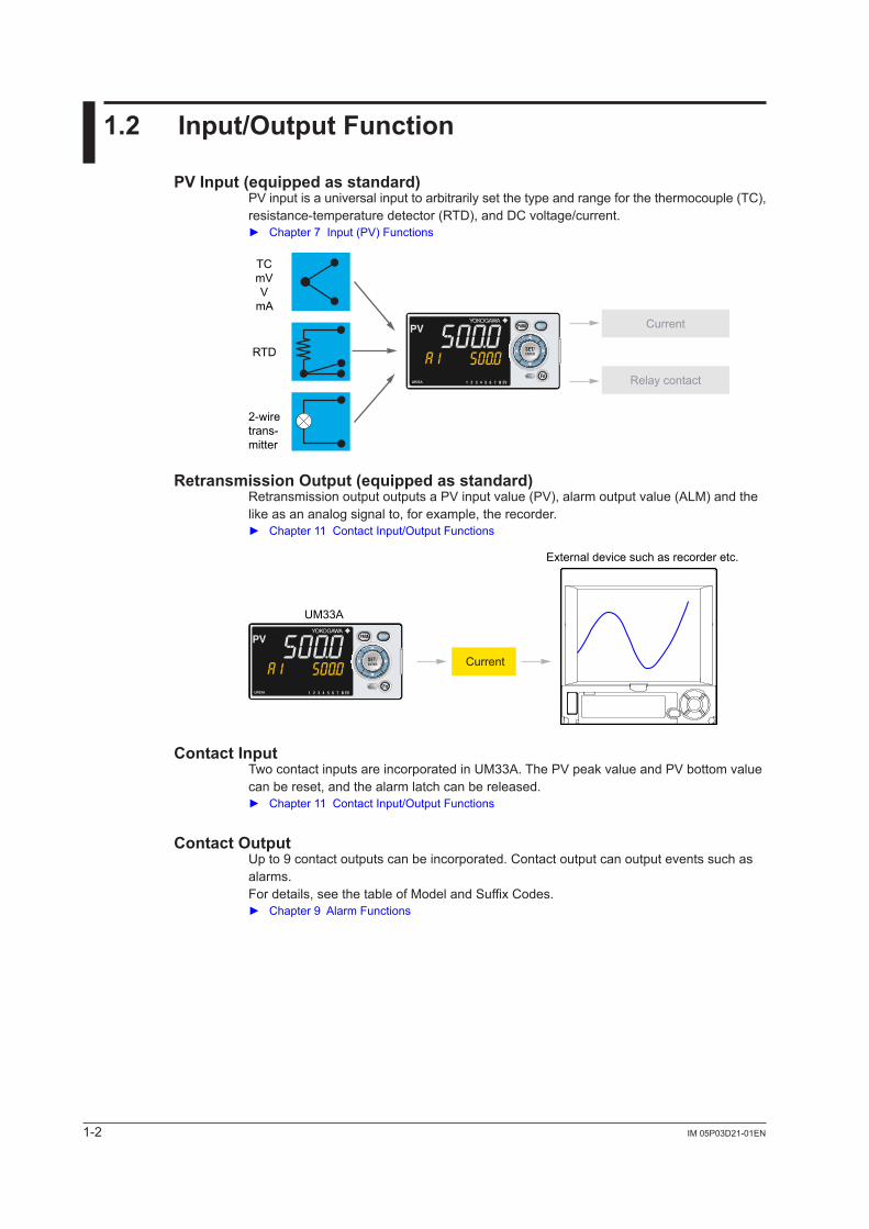
1.2 Input/Output Function
PV Input (equipped as standard)PVinputisauniversalinputtoarbitrarilysetthetypeandrangeforthethermocouple(TC),resistance-temperature detector (RTD), and DC voltage/current. Chapter7Input(PV)Functions
Current
Relay contact
TCmVV
mA
RTD
2-wiretrans-mitter
8
Retransmission Output (equipped as standard)RetransmissionoutputoutputsaPVinputvalue(PV),alarmoutputvalue (ALM) and the like as an analog signal to, for example, the recorder. Chapter11ContactInput/OutputFunctions
Current
External device such as recorder etc.
UM33A
8
Contact InputTwocontactinputsareincorporatedinUM33A.ThePVpeakvalueandPVbottomvaluecan be reset, and the alarm latch can be released. Chapter 11 Contact Input/Output Functions
Contact OutputUp to 9 contact outputs can be incorporated. Contact output can output events such as alarms.For details, see the table of Model and Suffix Codes. Chapter9AlarmFunctions
1-3IM 05P03D21-01EN
Introduction to Functions
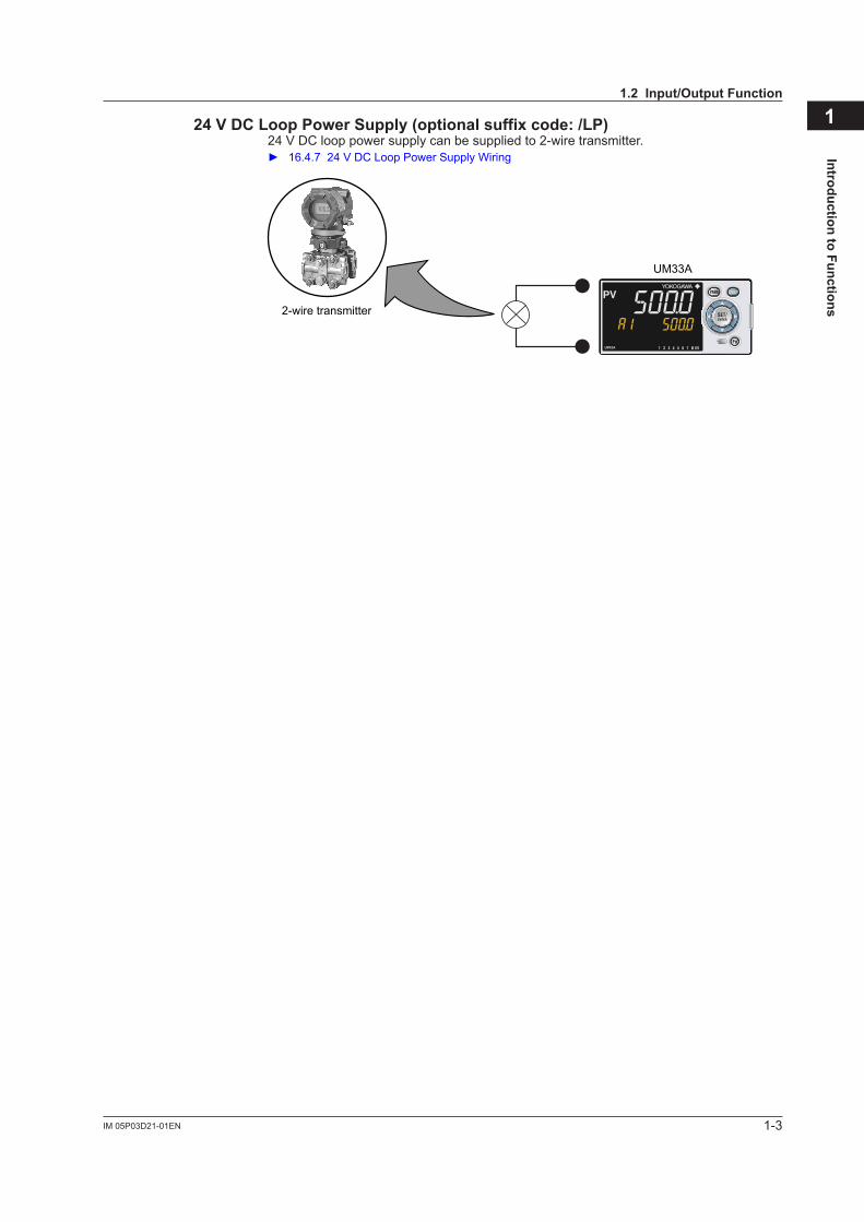
124 V DC Loop Power Supply (optional suffix code: /LP)24VDClooppowersupplycanbesuppliedto2-wiretransmitter. 16.4.724VDCLoopPowerSupplyWiring
2-wire transmitter
UM33A
8
1.2 Input/Output Function
1-4 IM 05P03D21-01EN
1.3 Display and Key Functions
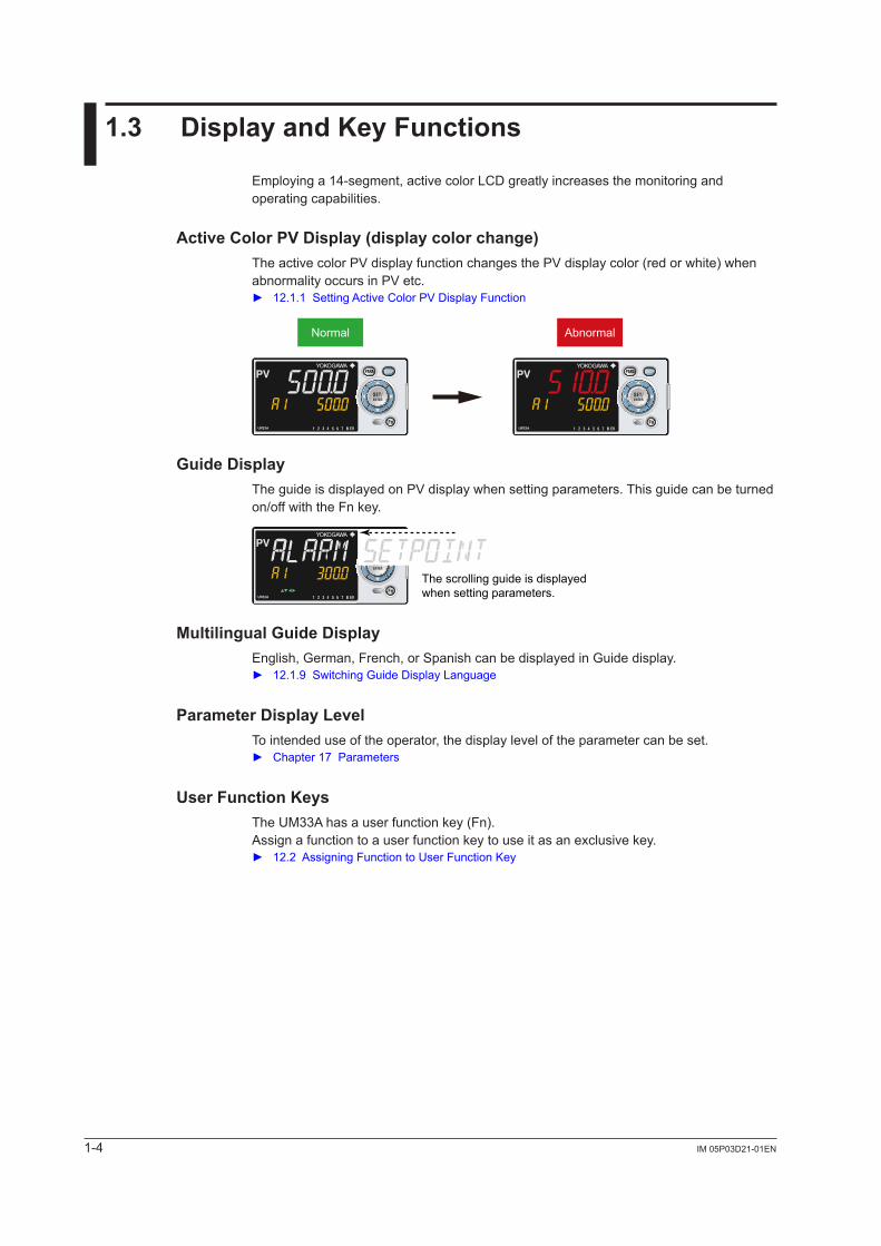
Employing a 14-segment, active color LCD greatly increases the monitoring and operating capabilities.
Active Color PV Display (display color change)TheactivecolorPVdisplayfunctionchangesthePVdisplaycolor(redorwhite)whenabnormalityoccursinPVetc. 12.1.1SettingActiveColorPVDisplayFunction
Normal Abnormal
8 8
Guide DisplayTheguideisdisplayedonPVdisplaywhensettingparameters.Thisguidecanbeturnedon/off with the Fn key.
The scrolling guide is displayed when setting parameters.8
Multilingual Guide DisplayEnglish, German, French, or Spanish can be displayed in Guide display. 12.1.9SwitchingGuideDisplayLanguage
Parameter Display LevelTo intended use of the operator, the display level of the parameter can be set. Chapter17Parameters
User Function KeysThe UM33A has a user function key (Fn).Assign a function to a user function key to use it as an exclusive key. 12.2AssigningFunctiontoUserFunctionKey
1-5IM 05P03D21-01EN
Introduction to Functions
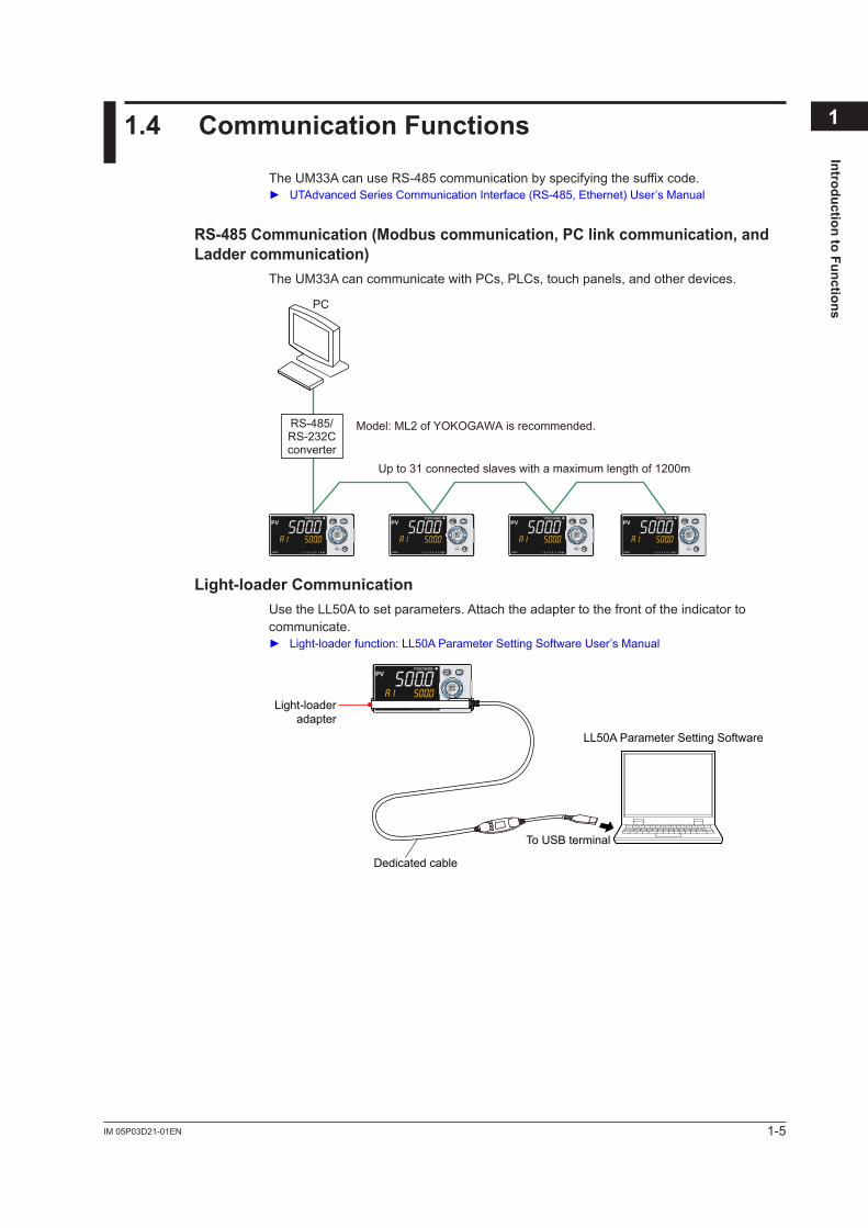
11.4 Communication Functions
The UM33A can use RS-485 communication by specifying the suffix code. UTAdvancedSeriesCommunicationInterface(RS-485,Ethernet)User’sManual
RS-485 Communication (Modbus communication, PC link communication, and Ladder communication)
The UM33A can communicate with PCs, PLCs, touch panels, and other devices.
Up to 31 connected slaves with a maximum length of 1200m
Model: ML2 of YOKOGAWA is recommended.RS-485/RS-232Cconverter
PC
8 8 8 8
Light-loader CommunicationUse the LL50A to set parameters. Attach the adapter to the front of the indicator to communicate. Light-loaderfunction:LL50AParameterSettingSoftwareUser’sManual
Dedicated cable
LL50A Parameter Setting Software
To USB terminal
8Light-loaderadapter
1-6 IM 05P03D21-01EN
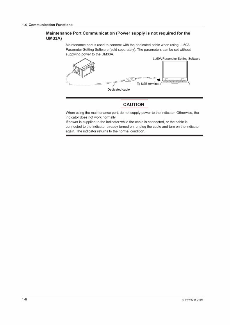
Maintenance Port Communication (Power supply is not required for the UM33A)
Maintenance port is used to connect with the dedicated cable when using LL50A Parameter Setting Software (sold separately). The parameters can be set without supplying power to the UM33A.
Dedicated cable
LL50A Parameter Setting Software
To USB terminal
CAUTIONWhen using the maintenance port, do not supply power to the indicator. Otherwise, the indicator does not work normally. If power is supplied to the indicator while the cable is connected, or the cable is connected to the indicator already turned on, unplug the cable and turn on the indicator again. The indicator returns to the normal condition.
1.4 Communication Functions
1-7IM 05P03D21-01EN
Introduction to Functions
11.5 Definition of Main Symbols and Terms
Main SymbolPV:MeasuredinputvalueA1 to A8: Alarm setpoint
PEAK:PVpeakvalueBOTM:PVbottomvalues 16.4 Wiring
Engineering UnitsInputrange(scale):thePVrangelowlimitissetto0%,andthehighlimitissetto100%for conversion.Inputrange(scale)span:thePVrangespanissetto100%forconversion.
In this manual, the parameter setting range is described as the “input range” and “input range span.” This means that engineering units are required to be set. Set a temperature for temperature input.
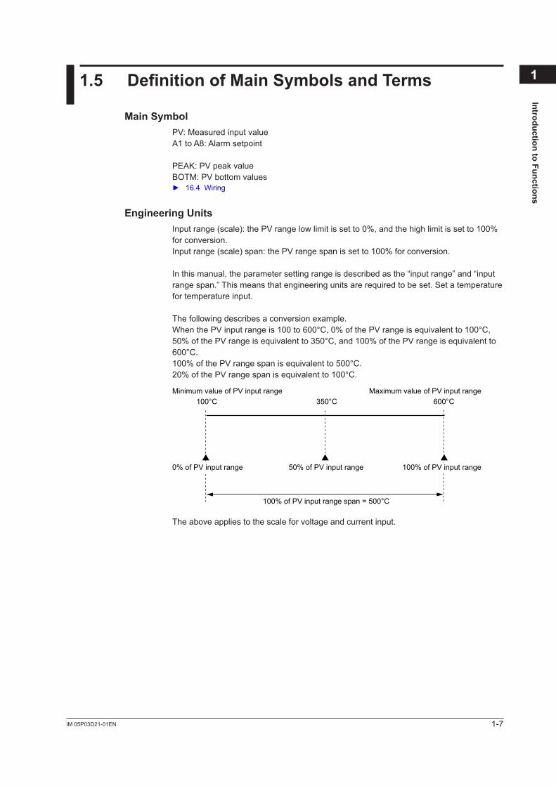
The following describes a conversion example.WhenthePVinputrangeis100to600°C,0%ofthePVrangeisequivalentto100°C,50%ofthePVrangeisequivalentto350°C,and100%ofthePVrangeisequivalentto600°C.100%ofthePVrangespanisequivalentto500°C.20%ofthePVrangespanisequivalentto100°C.
Minimum value of PV input range Maximum value of PV input range100°C 600°C350°C
50% of PV input range
100% of PV input range span = 500°C
0% of PV input range 100% of PV input range
The above applies to the scale for voltage and current input.

Blank Page
2-1IM 05P03D21-01EN
UM
33A Operating Procedures
22.1 UM33A Operating Procedures
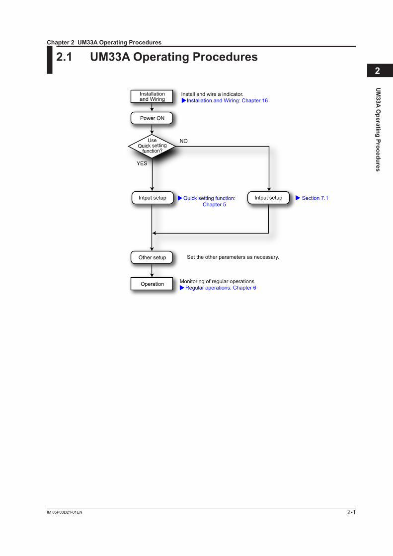
Install and wire a indicator. Installation and Wiring: Chapter 16
Quick setting function: Chapter 5
Monitoring of regular operations Regular operations: Chapter 6
Section 7.1
Other setup
Operation
NO
YES
Set the other parameters as necessary.
Intput setupIntput setup
Installationand Wiring
Power ON
UseQuick setting
function?
Chapter 2 UM33A Operating Procedures

Blank Page
3-1IM 05P03D21-01EN
Part Nam
es
3
3.1 Names and Functions of Display Parts
UM33A
8
(1) PV display
(2) Group display
(8) Security indicator
(4) Data display
(2) + (3) + (4) : Setpoint display
(3) Symbol display
(5) Event indicator(6) Key navigation indicator
(7) Parameter display level indicator
No.infigure Name Description
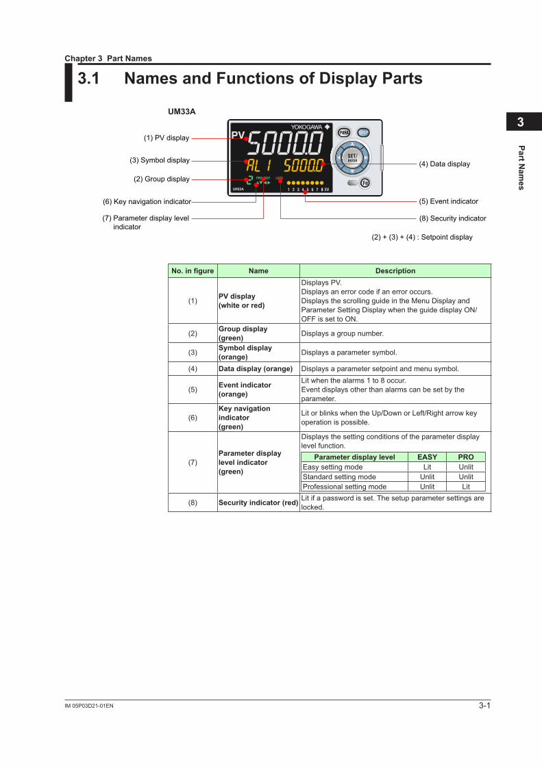
(1) PV display (white or red)
DisplaysPV.Displays an error code if an error occurs.Displays the scrolling guide in the Menu Display and Parameter Setting Display when the guide display ON/OFF is set to ON.
(2) Group display (green) Displays a group number.
(3) Symbol display (orange) Displays a parameter symbol.
(4) Data display (orange) Displays a parameter setpoint and menu symbol.
(5) Event indicator (orange)
Lit when the alarms 1 to 8 occur.Event displays other than alarms can be set by the parameter.
(6)Key navigation indicator (green)
Lit or blinks when the Up/Down or Left/Right arrow key operation is possible.
(7)Parameter display level indicator (green)
Displays the setting conditions of the parameter display level function.
Parameter display level EASY PROEasy setting mode Lit UnlitStandard setting mode Unlit UnlitProfessional setting mode Unlit Lit
(8) Security indicator (red) Lit if a password is set. The setup parameter settings are locked.
Chapter 3 Part Names
3-2 IM 05P03D21-01EN
3.2 Names and Functions of Keys
UM33A
8
(4) Light-loader interface
(6) User function keys
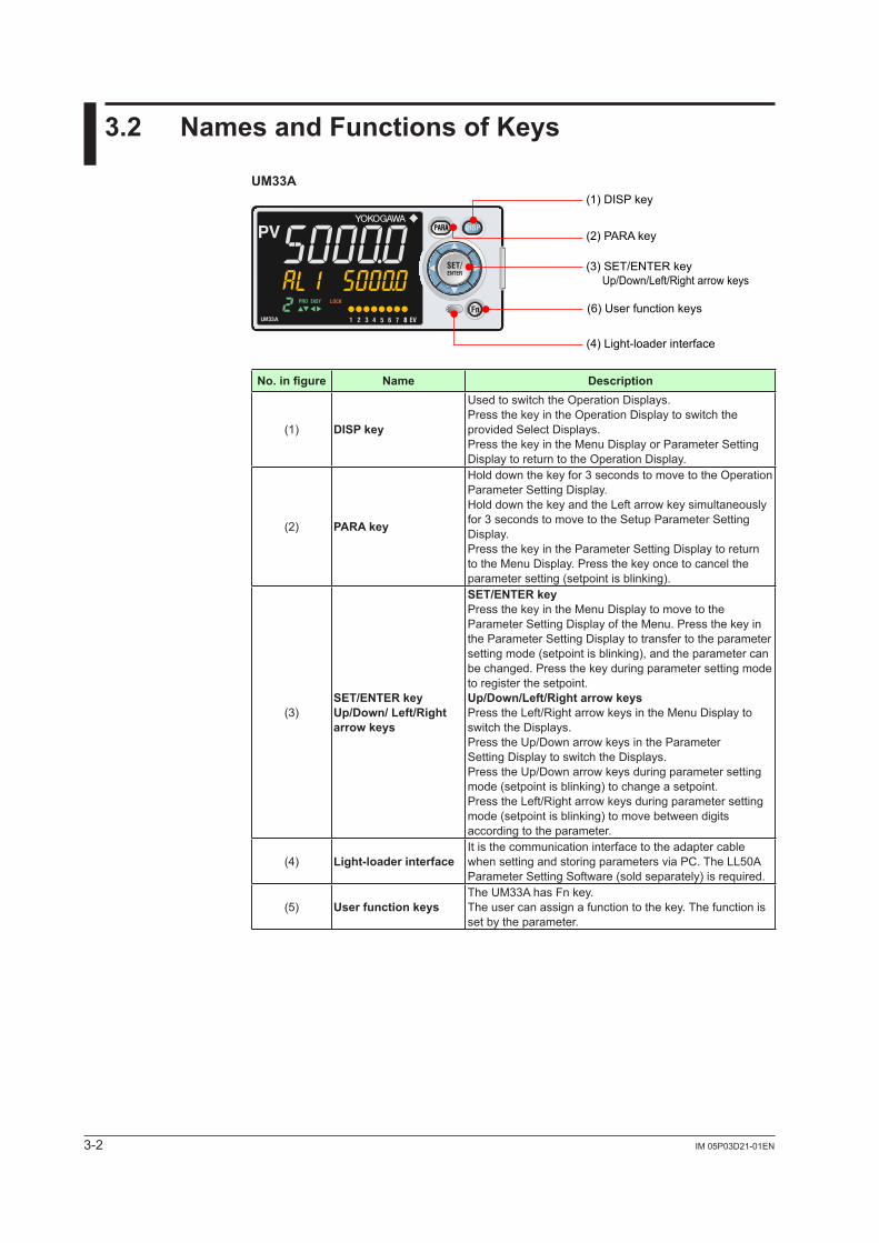
(1) DISP key
(2) PARA key
(3) SET/ENTER key Up/Down/Left/Right arrow keys
No.infigure Name Description
(1) DISP key
Used to switch the Operation Displays.Press the key in the Operation Display to switch the provided Select Displays.Press the key in the Menu Display or Parameter Setting Display to return to the Operation Display.
(2) PARA key
Hold down the key for 3 seconds to move to the Operation Parameter Setting Display.Hold down the key and the Left arrow key simultaneously for 3 seconds to move to the Setup Parameter Setting Display.Press the key in the Parameter Setting Display to return to the Menu Display. Press the key once to cancel the parameter setting (setpoint is blinking).
(3)SET/ENTER keyUp/Down/ Left/Right arrow keys
SET/ENTER keyPress the key in the Menu Display to move to the Parameter Setting Display of the Menu. Press the key in the Parameter Setting Display to transfer to the parameter setting mode (setpoint is blinking), and the parameter can be changed. Press the key during parameter setting mode to register the setpoint.Up/Down/Left/Right arrow keysPress the Left/Right arrow keys in the Menu Display to switch the Displays.Press the Up/Down arrow keys in the ParameterSetting Display to switch the Displays.Press the Up/Down arrow keys during parameter setting mode (setpoint is blinking) to change a setpoint.Press the Left/Right arrow keys during parameter setting mode (setpoint is blinking) to move between digits according to the parameter.
(4) Light-loader interfaceIt is the communication interface to the adapter cable when setting and storing parameters via PC. The LL50A Parameter Setting Software (sold separately) is required.
(5) User function keysThe UM33A has Fn key.The user can assign a function to the key. The function is set by the parameter.
3-3IM 05P03D21-01EN
Part Nam
es
3
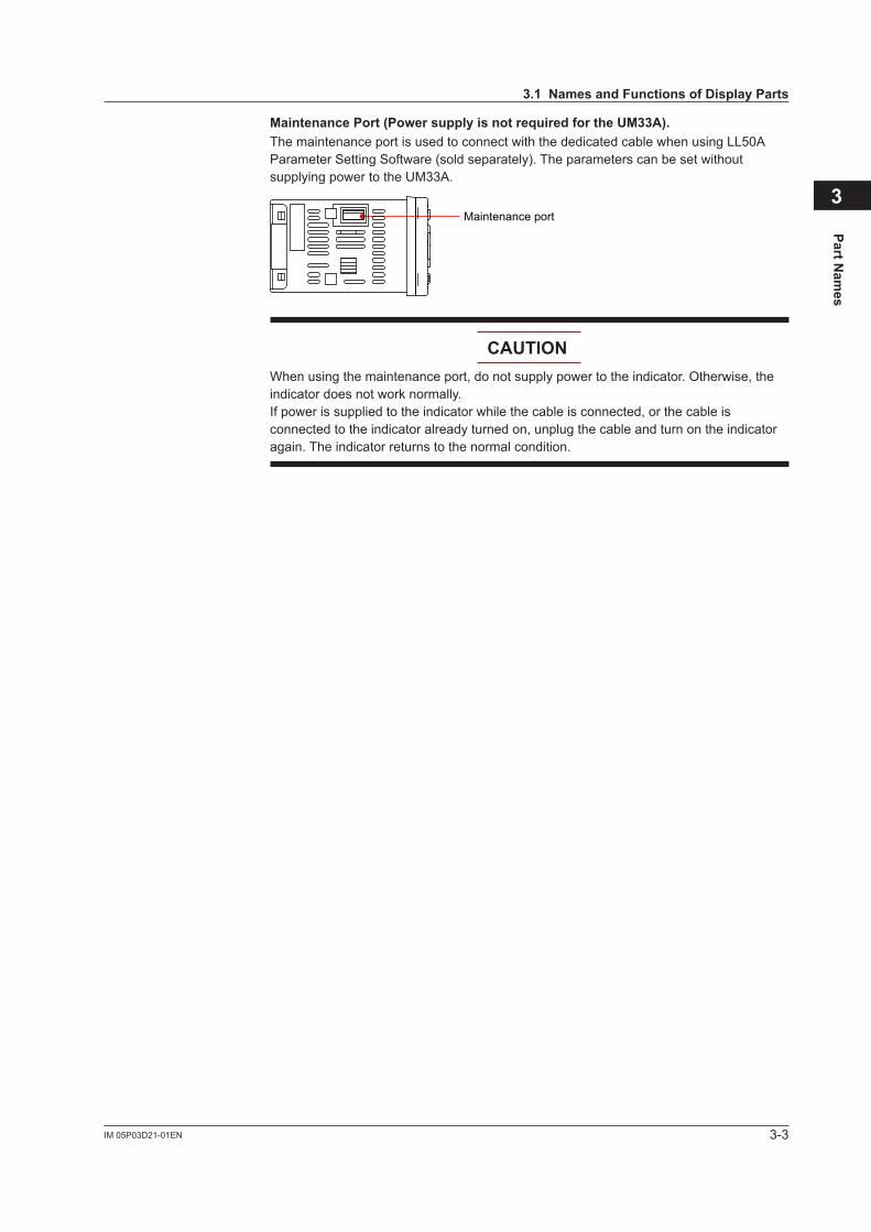
Maintenance Port (Power supply is not required for the UM33A).The maintenance port is used to connect with the dedicated cable when using LL50A Parameter Setting Software (sold separately). The parameters can be set without supplying power to the UM33A.
Maintenance port
CAUTIONWhen using the maintenance port, do not supply power to the indicator. Otherwise, the indicator does not work normally. If power is supplied to the indicator while the cable is connected, or the cable is connected to the indicator already turned on, unplug the cable and turn on the indicator again. The indicator returns to the normal condition.
3.1 Names and Functions of Display Parts

3-4 IM 05P03D21-01EN
3.3 List of Display Symbols
The following shows the parameter symbols, menu symbols, alphanumeric of guide, and symbols which are displayed on the UM33A.
Figure (common to all display area)
0 1 2 3 4 5 6 7 8 9
PV display (14 segments): Alphabet
A B C D E F
G H I J K L
M N O P Q R
S T U V W X
Y Z
Symbol display and Data display (11 segments): Alphabet
c (lower-case)
A B C D E F
G H I J K L
M N O P Q R
S T U V W X
Y Z
3-5IM 05P03D21-01EN
Part Nam
es
3
3.2 Names and Functions of Keys
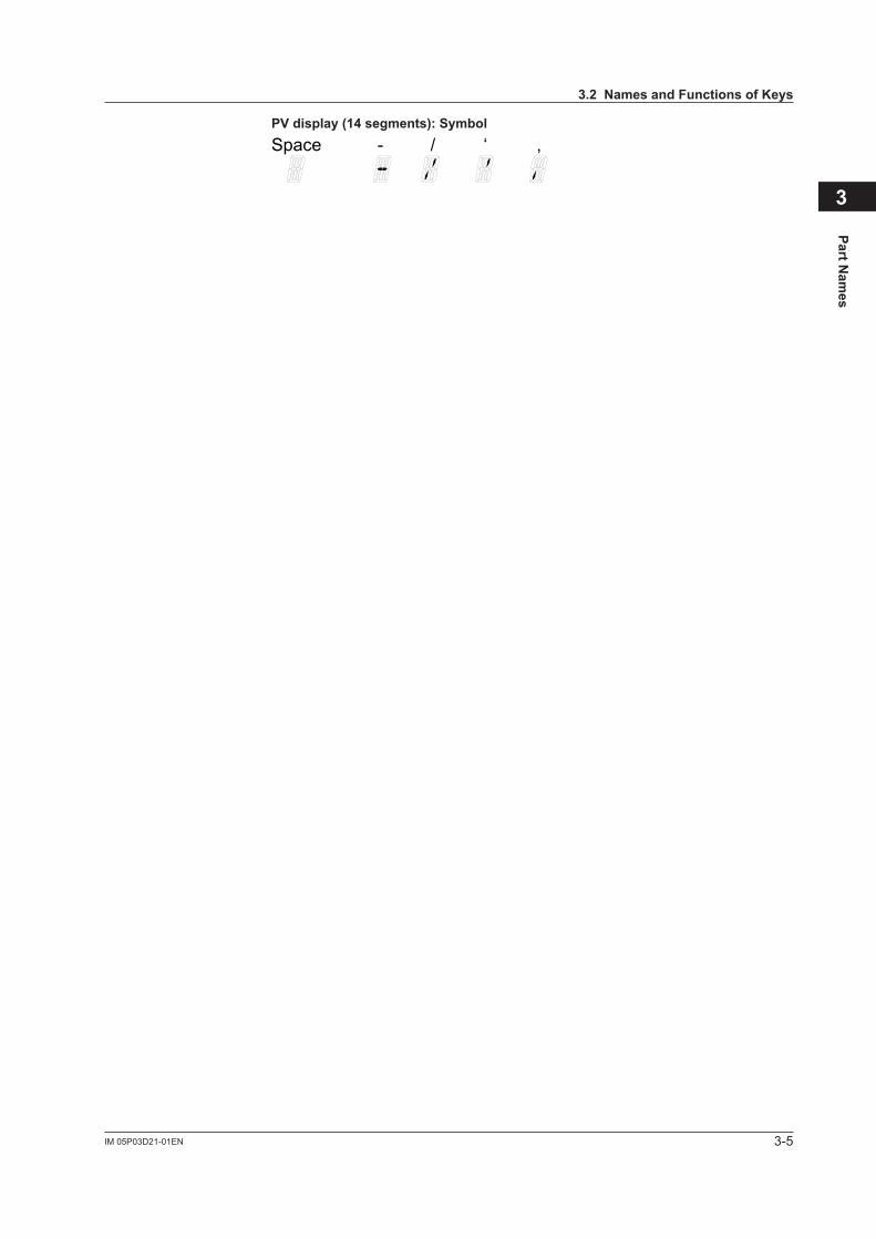
PV display (14 segments): Symbol
Space - / ‘ ,
3-6 IM 05P03D21-01EN
3.4 Brief Description of Setting Details (Parameters)
This manual describes the Setting Details as follows in addition to the functional Description.
Setting Details
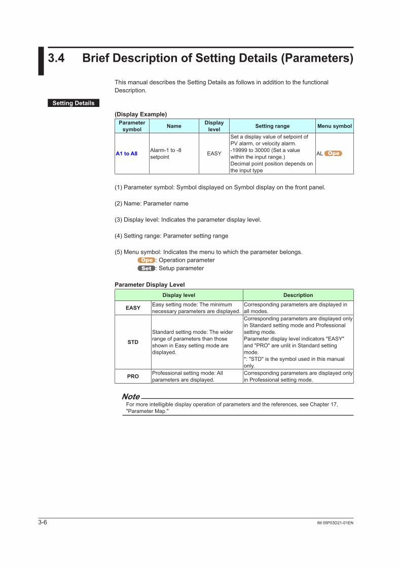
(Display Example)Parameter
symbol Name Display level Setting range Menu symbol
A1 to A8 Alarm-1 to -8 setpoint EASY
Set a display value of setpoint of PValarm,orvelocityalarm.-19999 to 30000 (Set a value within the input range.)Decimal point position depends on the input type
AL
(1) Parameter symbol: Symbol displayed on Symbol display on the front panel.
(2) Name: Parameter name
(3) Display level: Indicates the parameter display level.
(4) Setting range: Parameter setting range
(5) Menu symbol: Indicates the menu to which the parameter belongs.: Operation parameter: Setup parameter
Parameter Display LevelDisplay level Description
EASY Easy setting mode: The minimum necessary parameters are displayed.
Corresponding parameters are displayed in all modes.
STD
Standard setting mode: The wider range of parameters than those shown in Easy setting mode are displayed.
Corresponding parameters are displayed only in Standard setting mode and Professional setting mode.Parameter display level indicators "EASY" and "PRO" are unlit in Standard setting mode.*: "STD" is the symbol used in this manual only.
PRO Professional setting mode: All parameters are displayed.
Corresponding parameters are displayed only in Professional setting mode.
NoteFor more intelligible display operation of parameters and the references, see Chapter 17, "Parameter Map."
4-1IM 05P03D21-01EN
Basic O
peration
4
4.1 Overview of Display Switch and Operation Keys
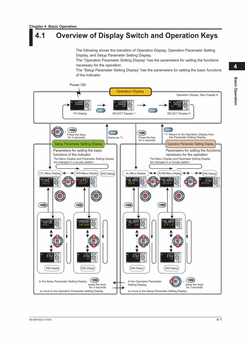
The following shows the transition of Operation Display, Operation Parameter Setting Display, and Setup Parameter Setting Display.The “Operation Parameter Setting Display” has the parameters for setting the functions necessary for the operation.The “Setup Parameter Setting Display” has the parameters for setting the basic functions of the indicator.
8 8 8
8 8 8 8 8
88
8 88 8
88
*1* Return to the Operation Display from the Parameter Setting DisplaySame as *1. Press the key
for 3 seconds.
Press the keys for 3 seconds.
+
AL Menu DisplayVER Menu DisplayCTL Menu Display ALRM Menu Display END DisplayEND Display
END DisplayEND Display END DisplayEND Display
press the keysfor 3 seconds
+In the Setup Parameter Setting Display, In the Operation Parameter Setting Display,
to move to the Operation Parameter Setting Display. to move to the Setup Parameter Setting Display.
press the keys for 3 seconds
The Menu Display and Parameter Setting Display are changed in a circular pattern.
The Menu Display and Parameter Setting Display are changed in a circular pattern.
Operation Parameter Setting DisplaySetup Parameter Setting Display
Parameters for setting the basicfunctions of the indicator
Parameters for setting the functionsnecessary for the operation
• • • • • ••
• •
• •
•
• •
•
• •
•
PV Display
Power ON
SELECT Display-1 SELECT Display-5
Operation Display: See Chapter 6.Operation Display
Chapter 4 Basic Operation
4-2 IM 05P03D21-01EN
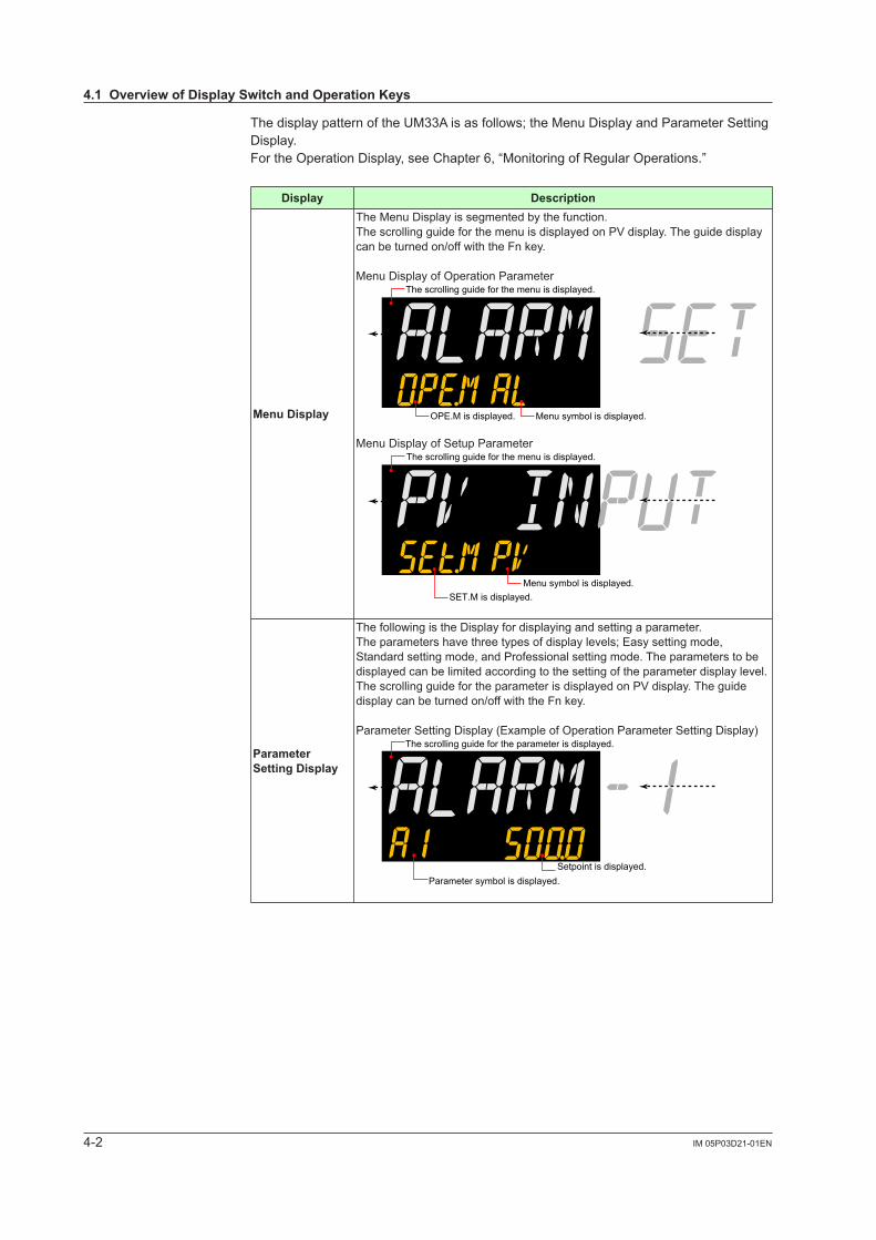
The display pattern of the UM33A is as follows; the Menu Display and Parameter Setting Display.For the Operation Display, see Chapter 6, “Monitoring of Regular Operations.”
Display Description
Menu Display
The Menu Display is segmented by the function.ThescrollingguideforthemenuisdisplayedonPVdisplay.Theguidedisplaycan be turned on/off with the Fn key.
Menu Display of Operation ParameterThe scrolling guide for the menu is displayed.
OPE.M is displayed. Menu symbol is displayed.
Menu Display of Setup ParameterThe scrolling guide for the menu is displayed.
SET.M is displayed.Menu symbol is displayed.
Parameter Setting Display
The following is the Display for displaying and setting a parameter.The parameters have three types of display levels; Easy setting mode, Standard setting mode, and Professional setting mode. The parameters to be displayed can be limited according to the setting of the parameter display level.ThescrollingguidefortheparameterisdisplayedonPVdisplay.Theguidedisplay can be turned on/off with the Fn key.
Parameter Setting Display (Example of Operation Parameter Setting Display)The scrolling guide for the parameter is displayed.
Setpoint is displayed.Parameter symbol is displayed.
4.1 Overview of Display Switch and Operation Keys
4-3IM 05P03D21-01EN
Basic O
peration
4
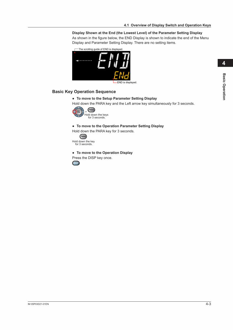
Display Shown at the End (the Lowest Level) of the Parameter Setting DisplayAs shown in the figure below, the END Display is shown to indicate the end of the Menu Display and Parameter Setting Display. There are no setting items.
END is displayed.
The scrolling guide of END is displayed.
Basic Key Operation Sequence TomovetotheSetupParameterSettingDisplayHold down the PARA key and the Left arrow key simultaneously for 3 seconds.
Hold down the keys for 3 seconds.
+
TomovetotheOperationParameterSettingDisplayHold down the PARA key for 3 seconds.
Hold down the key for 3 seconds.
TomovetotheOperationDisplayPress the DISP key once.
4.1 Overview of Display Switch and Operation Keys
4-4 IM 05P03D21-01EN
4.2 How to Set Parameters
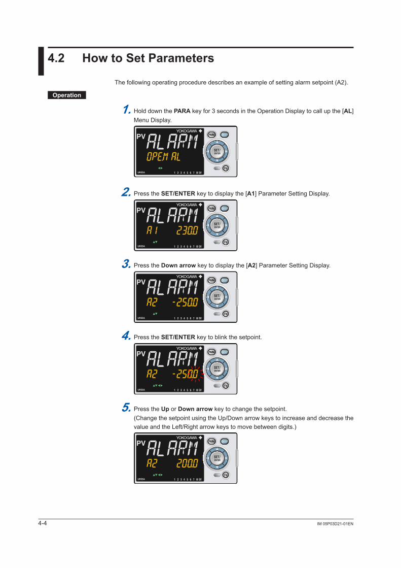
The following operating procedure describes an example of setting alarm setpoint (A2).
Operation
1. Hold down the PARA key for 3 seconds in the Operation Display to call up the [AL] Menu Display.
8
2. Press the SET/ENTER key to display the [A1] Parameter Setting Display.
8
3. Press the Down arrow key to display the [A2] Parameter Setting Display.
8
4. Press the SET/ENTER key to blink the setpoint.
8
5. Press the Up or Down arrow key to change the setpoint. (Change the setpoint using the Up/Down arrow keys to increase and decrease the value and the Left/Right arrow keys to move between digits.)
8
4-5IM 05P03D21-01EN
Basic O
peration
4
4.2 How to Set Parameters
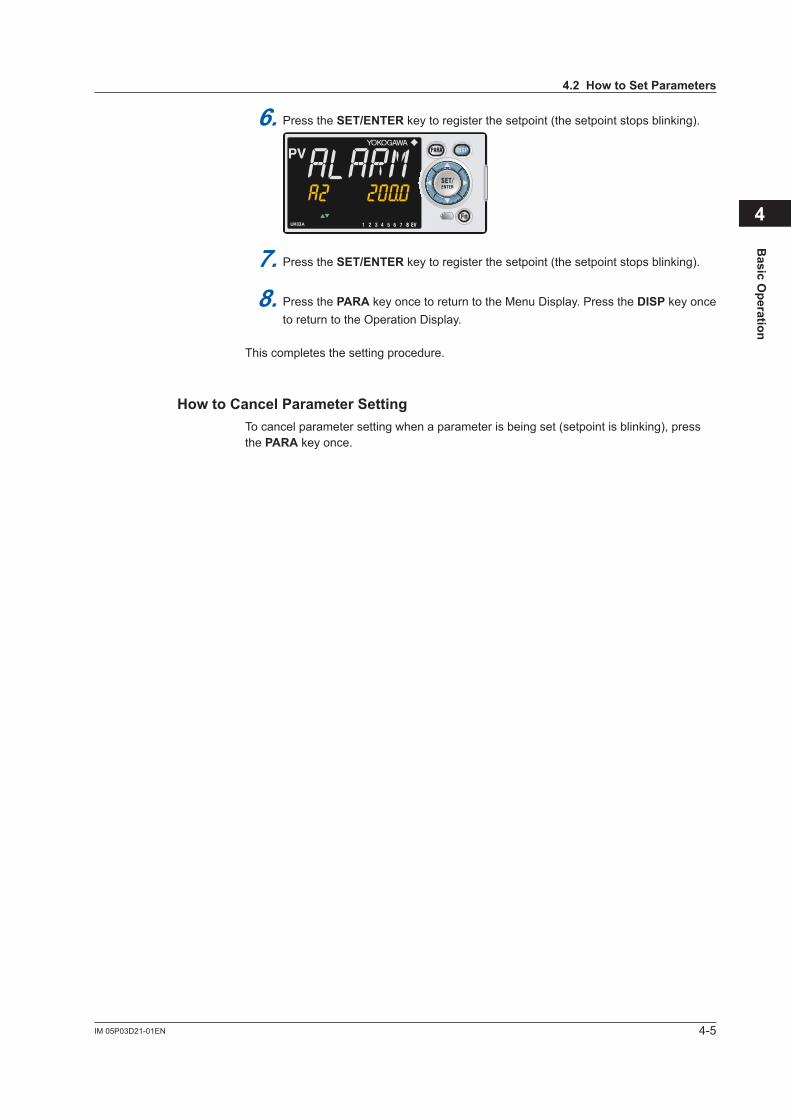
6. Press the SET/ENTER key to register the setpoint (the setpoint stops blinking).
8
7. Press the SET/ENTER key to register the setpoint (the setpoint stops blinking).
8. Press the PARA key once to return to the Menu Display. Press the DISP key once to return to the Operation Display.
This completes the setting procedure.
How to Cancel Parameter SettingTo cancel parameter setting when a parameter is being set (setpoint is blinking), press the PARA key once.
4-6 IM 05P03D21-01EN
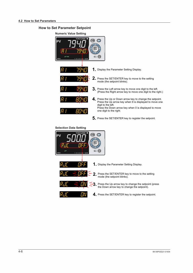
How to Set Parameter SetpointNumeric Value Setting
1.
2.
3.
4.
5.
Press the Left arrow key to move one digit to the left.(Press the Right arrow key to move one digit to the right.)
Press the Up or Down arrow key to change the setpoint. Press the Up arrow key when 9 is displayed to move one digit to the left.Press the Down arrow key when 0 is displayed to move one digit to the right.
Press the SET/ENTER key to register the setpoint.
Display the Parameter Setting Display.
Press the SET/ENTER key to move to the setting mode (the setpoint blinks).
8
Selection Data Setting
1.
2.
3.
4.
Press the Up arrow key to change the setpoint (press the Down arrow key to change the setpoint).
Press the SET/ENTER key to register the setpoint.
Display the Parameter Setting Display.
Press the SET/ENTER key to move to the setting mode (the setpoint blinks).
8
4.2 How to Set Parameters
4-7IM 05P03D21-01EN
Basic O
peration
4
4.2 How to Set Parameters
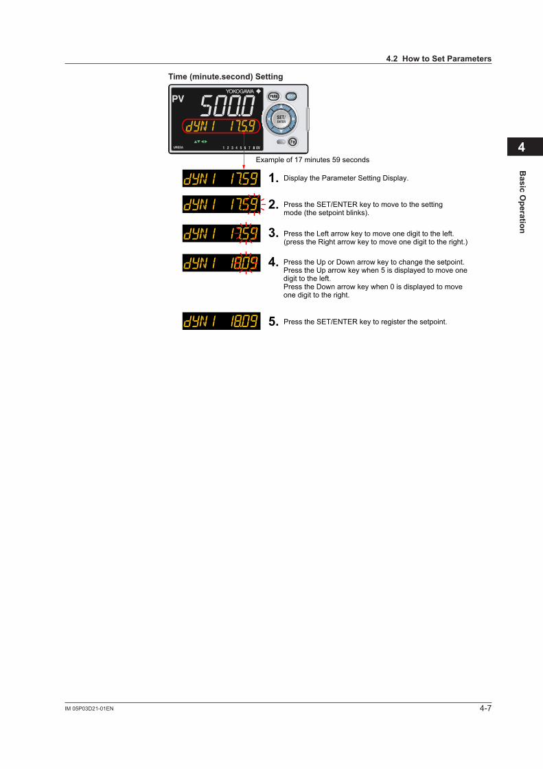
Time (minute.second) Setting
1.
2.
3.
4.
5.
Example of 17 minutes 59 seconds
Press the Left arrow key to move one digit to the left.(press the Right arrow key to move one digit to the right.)
Press the SET/ENTER key to register the setpoint.
Display the Parameter Setting Display.
Press the SET/ENTER key to move to the setting mode (the setpoint blinks).
Press the Up or Down arrow key to change the setpoint. Press the Up arrow key when 5 is displayed to move one digit to the left.Press the Down arrow key when 0 is displayed to move one digit to the right.
8

Blank Page
5-1IM 05P03D21-01EN
Quick Setting Function
5
5.1 Setting Using Quick Setting Function
Description
The Quick setting function is a function to easily set the basic function of the indicator.The Quick setting function starts when the power is turned on after wiring.
The following lists the items to set using the Quick setting function.(1) Inputfunction(PVinput,range,scale(atvoltage/currentinput),etc.)
Chapter 5 Quick Setting Function
5-2 IM 05P03D21-01EN
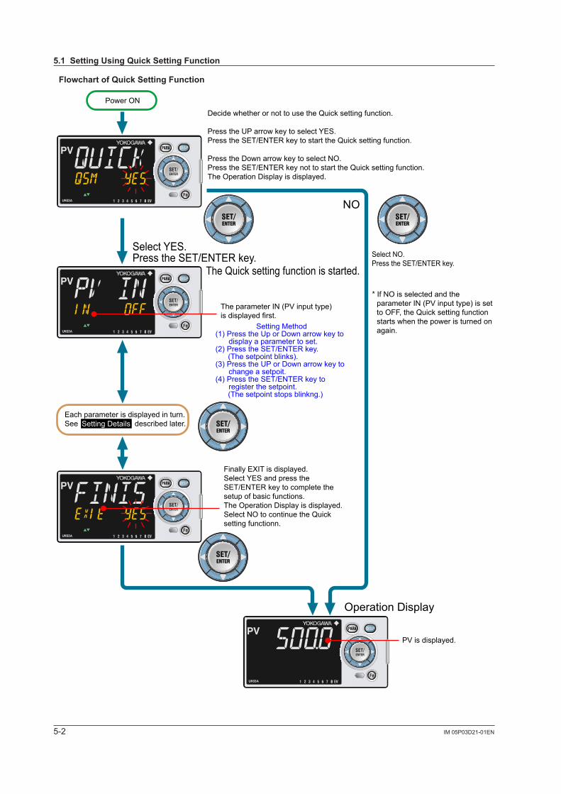
Flowchart of Quick Setting Function
8
8
8
8
Decide whether or not to use the Quick setting function.
Press the UP arrow key to select YES.Press the SET/ENTER key to start the Quick setting function.
Press the Down arrow key to select NO.Press the SET/ENTER key not to start the Quick setting function.The Operation Display is displayed.
Select YES.Press the SET/ENTER key.
The Quick setting function is started.
NO
Each parameter is displayed in turn.See described later.
Select NO.Press the SET/ENTER key.
Operation Display
Power ON
The parameter IN (PV input type)is displayed first.
PV is displayed.
Finally EXIT is displayed. Select YES and press the SET/ENTER key to complete the setup of basic functions.The Operation Display is displayed.Select NO to continue the Quick setting functionn.
Setting Method(1) Press the Up or Down arrow key to
display a parameter to set.(2) Press the SET/ENTER key. (The setpoint blinks).(3) Press the UP or Down arrow key to
change a setpoit.(4) Press the SET/ENTER key to
register the setpoint. (The setpoint stops blinkng.)
Setting Details
* If NO is selected and the parameter IN (PV input type) is set to OFF, the Quick setting function starts when the power is turned on again.
5.1 Setting Using Quick Setting Function
5-3IM 05P03D21-01EN
Quick Setting Function
5
Setting ExampleSet the following parameters to set to thermocouple Type K (range: 0.0 to 500.0ºC). No need to change the parameters other than the following parameters.
Set QSM = YES to enter the quick setting mode.
(1) Set IN = K1.(2) Set UNIT = C (initial value).(3) Set RH = 500.0(4) Set RL = 0.0.
SetEXIT=YEStoquitthequicksettingmode.The Operation Display is shown.
5.1 Setting Using Quick Setting Function
5-4 IM 05P03D21-01EN
Setting Details
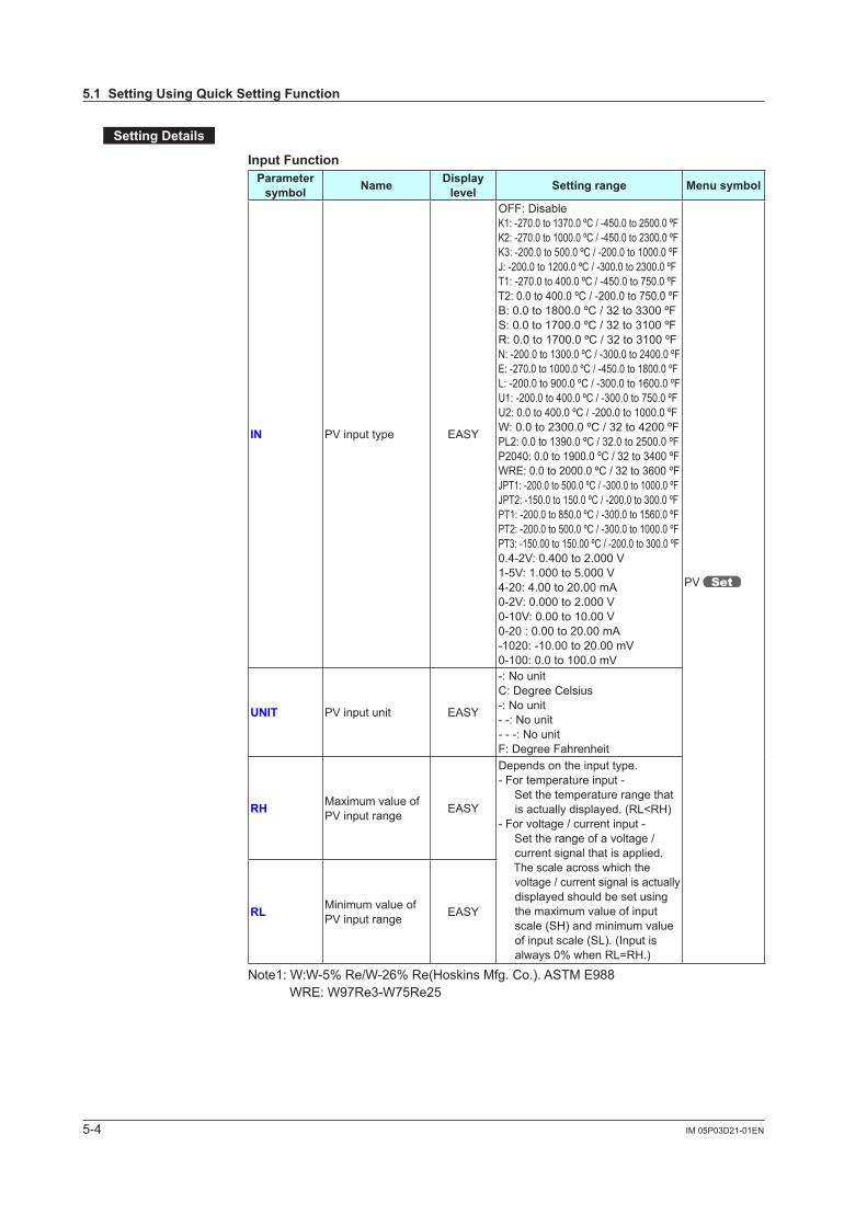
Input FunctionParameter
symbol Name Display level Setting range Menu symbol
IN PVinputtype EASY
OFF: DisableK1: -270.0 to 1370.0 ºC / -450.0 to 2500.0 ºFK2: -270.0 to 1000.0 ºC / -450.0 to 2300.0 ºFK3: -200.0 to 500.0 ºC / -200.0 to 1000.0 ºFJ: -200.0 to 1200.0 ºC / -300.0 to 2300.0 ºFT1: -270.0 to 400.0 ºC / -450.0 to 750.0 ºFT2: 0.0 to 400.0 ºC / -200.0 to 750.0 ºFB: 0.0 to 1800.0 ºC / 32 to 3300 ºFS: 0.0 to 1700.0 ºC / 32 to 3100 ºFR: 0.0 to 1700.0 ºC / 32 to 3100 ºFN: -200.0 to 1300.0 ºC / -300.0 to 2400.0 ºFE: -270.0 to 1000.0 ºC / -450.0 to 1800.0 ºFL: -200.0 to 900.0 ºC / -300.0 to 1600.0 ºFU1: -200.0 to 400.0 ºC / -300.0 to 750.0 ºFU2: 0.0 to 400.0 ºC / -200.0 to 1000.0 ºFW: 0.0 to 2300.0 ºC / 32 to 4200 ºFPL2: 0.0 to 1390.0 ºC / 32.0 to 2500.0 ºFP2040: 0.0 to 1900.0 ºC / 32 to 3400 ºFWRE: 0.0 to 2000.0 ºC / 32 to 3600 ºFJPT1: -200.0 to 500.0 ºC / -300.0 to 1000.0 ºFJPT2: -150.0 to 150.0 ºC / -200.0 to 300.0 ºFPT1: -200.0 to 850.0 ºC / -300.0 to 1560.0 ºFPT2: -200.0 to 500.0 ºC / -300.0 to 1000.0 ºFPT3: -150.00 to 150.00 ºC / -200.0 to 300.0 ºF0.4-2V:0.400to2.000V1-5V:1.000to5.000V4-20: 4.00 to 20.00 mA0-2V:0.000to2.000V0-10V:0.00to10.00V0-20 : 0.00 to 20.00 mA-1020:-10.00to20.00mV0-100:0.0to100.0mV
PV
UNIT PVinputunit EASY
-: No unitC: Degree Celsius-: No unit- -: No unit- - -: No unitF: Degree Fahrenheit
RH Maximum value of PVinputrange EASY
Depends on the input type.- For temperature input - Set the temperature range that
is actually displayed. (RL<RH)- For voltage / current input - Set the range of a voltage /
current signal that is applied. The scale across which the
voltage / current signal is actually displayed should be set using the maximum value of input scale (SH) and minimum value of input scale (SL). (Input is always0%whenRL=RH.)
RL Minimum value of PVinputrange EASY
Note1:W:W-5%Re/W-26%Re(HoskinsMfg.Co.).ASTME988 WRE: W97Re3-W75Re25
5.1 Setting Using Quick Setting Function
5-5IM 05P03D21-01EN
Quick Setting Function
5
5.1 Setting Using Quick Setting Function
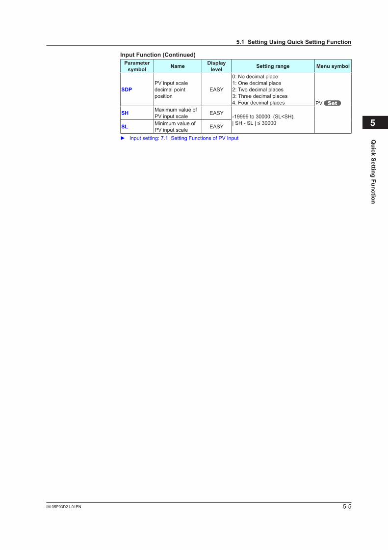
Input Function (Continued)Parameter
symbol Name Display level Setting range Menu symbol
SDPPVinputscaledecimal point position
EASY
0: No decimal place1: One decimal place2: Two decimal places3: Three decimal places4: Four decimal places PV
SH Maximum value of PVinputscale EASY
-19999 to 30000, (SL<SH),|SH-SL|≤30000SL Minimum value of
PVinputscale EASY
Inputsetting:7.1SettingFunctionsofPVInput
5-6 IM 05P03D21-01EN
5.2 Restarting Quick Setting Function
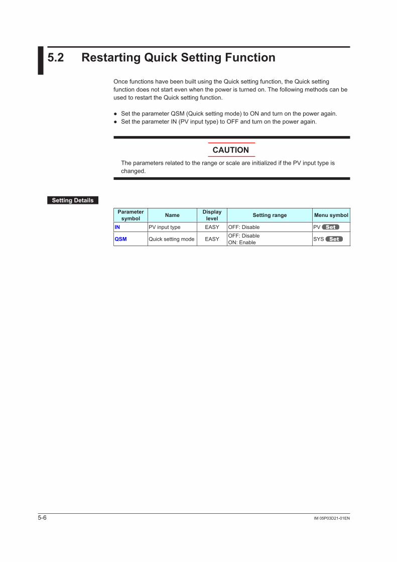
Once functions have been built using the Quick setting function, the Quick setting function does not start even when the power is turned on. The following methods can be used to restart the Quick setting function.
SettheparameterQSM(Quicksettingmode)toONandturnonthepoweragain. SettheparameterIN(PVinputtype)toOFFandturnonthepoweragain.
CAUTIONTheparametersrelatedtotherangeorscaleareinitializedifthePVinputtypeischanged.
Setting Details
Parameter symbol Name Display
level Setting range Menu symbol
IN PVinputtype EASY OFF: Disable PV
QSM Quick setting mode EASY OFF: DisableON: Enable SYS

6-1IM 05P03D21-01EN
Monitoring of R
egular Operations
6
6.1 Monitoring of Operation Displays
6.1.1 Operation Display Transitions Registration of SELECT Display: 12.1.3 Registering SELECT Display (Up to 5 displays)
SELECT Displays 1 to 5(Displayed only when SELECT Display is registered.(The figure on the left is the example of the parameter A1 (alarm-1 setpoint).)
SP Display (SP can be changed.)
Chapter 6 Monitoring of Regular Operations
6-2 IM 05P03D21-01EN
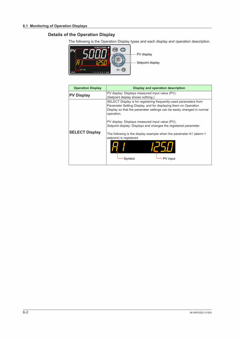
Details of the Operation DisplayThe following is the Operation Display types and each display and operation description.
PV display
Setpoint display
8
Operation Display Display and operation description
PV Display PVdisplay:Displaysmeasuredinputvalue(PV).(Setpoint display shows nothing.)
SELECT Display
SELECT Display is for registering frequently-used parameters from Parameter Setting Display, and for displaying them on Operation Display so that the parameter settings can be easily changed in normal operation.
PVdisplay:Displaysmeasuredinputvalue(PV).Setpoint display: Displays and changes the registered parameter.
The following is the display example when the parameter A1 (alarm-1 setpoint) is registered.
PV inputSymbol
6.1 Monitoring of Operation Displays
6-3IM 05P03D21-01EN
Monitoring of R
egular Operations
6
6.2 Setting Alarm Setpoint
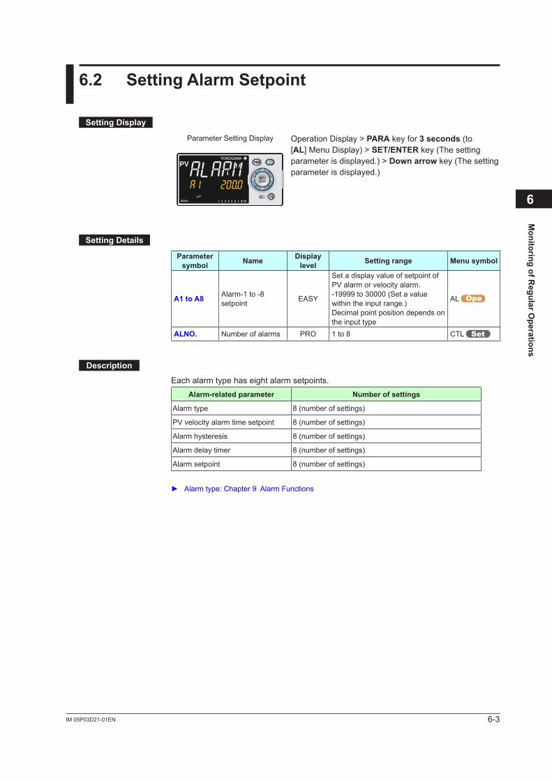
Setting Display
Parameter Setting Display
8
Operation Display > PARA key for 3 seconds (to [AL] Menu Display) > SET/ENTER key (The setting parameter is displayed.) > Down arrow key (The setting parameter is displayed.)
Setting Details
Parameter symbol Name Display
level Setting range Menu symbol
A1 to A8 Alarm-1 to -8 setpoint EASY
Set a display value of setpoint of PValarmorvelocityalarm.-19999 to 30000 (Set a value within the input range.)Decimal point position depends on the input type
AL
ALNO. Number of alarms PRO 1 to 8 CTL
Description
Each alarm type has eight alarm setpoints. Alarm-related parameter Number of settings
Alarm type 8 (number of settings)
PVvelocityalarmtimesetpoint 8 (number of settings)
Alarm hysteresis 8 (number of settings)
Alarm delay timer 8 (number of settings)
Alarm setpoint 8 (number of settings)
Alarmtype:Chapter9AlarmFunctions
6-4 IM 05P03D21-01EN
6.3 Releasing On-State (Latch) of Alarm Output
Description
Alarm latch can be released by any of the following. (1) User function key (2) Communication (3) Contact input For the switching operation by using the above, the last switching operation is performed.
Releasing the alarm latch function releases all of the latched alarm outputs.By factory default, the function is not assigned to the user function key. Assign and use the function in accordance with the reference sections below.
Releasebyuserfunctionkey:12.2AssigningFunctiontoUserFunctionKey Releasebycontactinput:11.1SettingContactInputFunction Releaseviacommunication:UTAdvancedSeriesCommunicationInterfaceUser’sManual

6-5IM 05P03D21-01EN
Monitoring of R
egular Operations
6
6.4 Confirmation of PV peak and bottom value
Description
DisplaysthemaximumvalueandminimumvalueofPVinputduringoperation.This parameter is not to be set.
Setting Details
Parameter symbol Name Display
level Setting range Menu symbol
PEAK PVpeakvalue EASY Display only-100.0to100.0%ofPVinputrange span (EUS)
PVSBOTM PVbottomvalue EASY
PVpeakandbottomvaluesreset:11.1SettingContactInputFunction

Blank Page
7-1IM 05P03D21-01EN
Input (PV) Functions
7
7.1 Setting Functions of PV Input
7.1.1 Setting Input Type, Unit, Range, Scale, and Decimal Point Position
Description
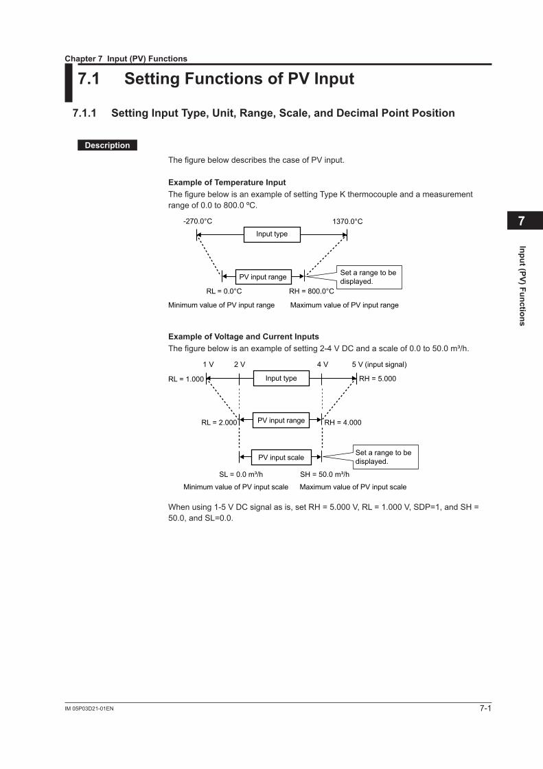
ThefigurebelowdescribesthecaseofPVinput.
Example of Temperature InputThe figure below is an example of setting Type K thermocouple and a measurement range of 0.0 to 800.0 ºC.
Minimum value of PV input range
Input type
-270.0°C 1370.0°C
RL = 0.0°C RH = 800.0°C
Maximum value of PV input range
Set a range to bedisplayed.PV input range
Example of Voltage and Current InputsThefigurebelowisanexampleofsetting2-4VDCandascaleof0.0to50.0m³/h.
Minimum value of PV input scale
1 V 5 V (input signal)
SL = 0.0 m³/h SH = 50.0 m³/h
Maximum value of PV input scale
2 V 4 V
RL = 2.000
RL = 1.000
RH = 4.000
RH = 5.000
PV input scale
Input type
Set a range to bedisplayed.
PV input range
Whenusing1-5VDCsignalasis,setRH=5.000V,RL=1.000V,SDP=1, and SH = 50.0, and SL=0.0.
Chapter 7 Input (PV) Functions
7-2 IM 05P03D21-01EN
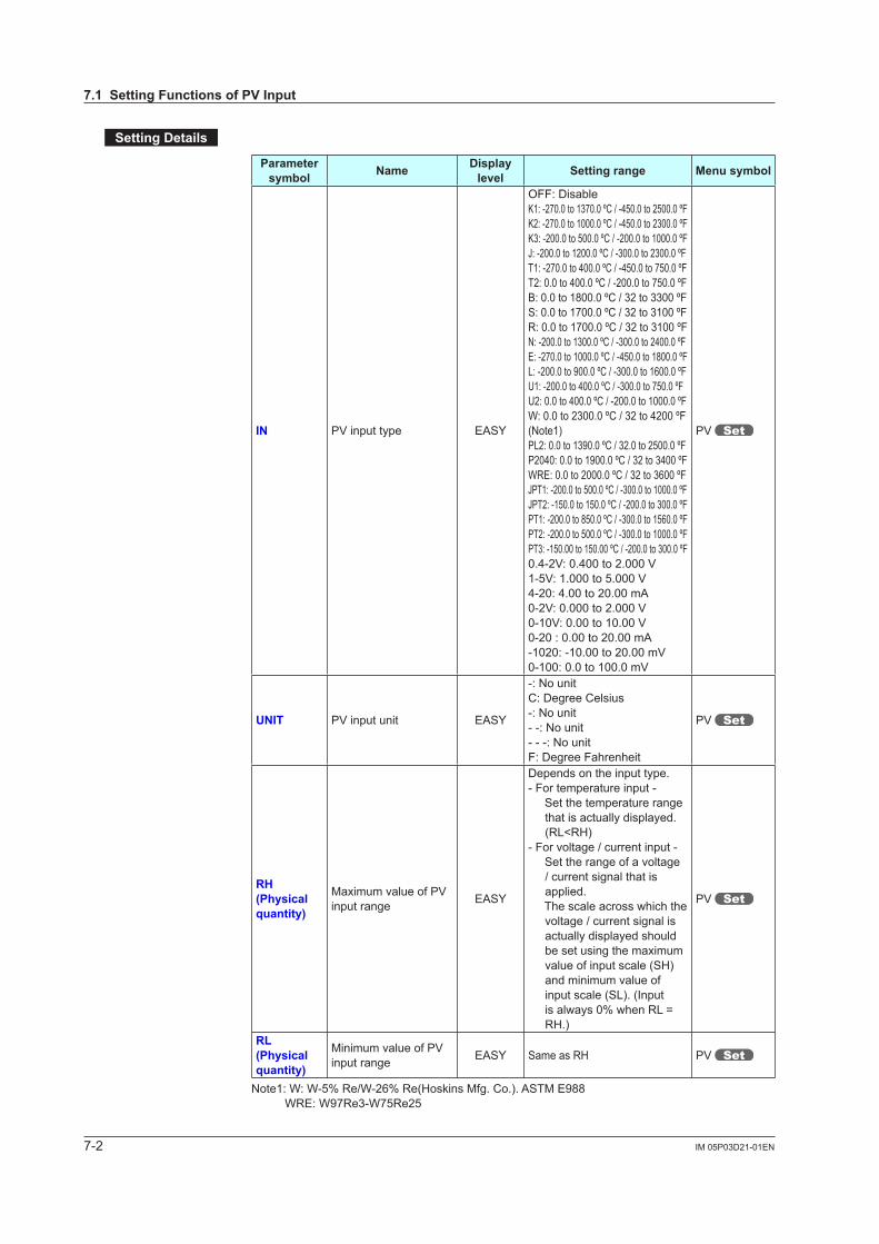
Setting Details
Parameter symbol Name Display
level Setting range Menu symbol
IN PVinputtype EASY
OFF: DisableK1: -270.0 to 1370.0 ºC / -450.0 to 2500.0 ºFK2: -270.0 to 1000.0 ºC / -450.0 to 2300.0 ºFK3: -200.0 to 500.0 ºC / -200.0 to 1000.0 ºFJ: -200.0 to 1200.0 ºC / -300.0 to 2300.0 ºFT1: -270.0 to 400.0 ºC / -450.0 to 750.0 ºFT2: 0.0 to 400.0 ºC / -200.0 to 750.0 ºFB: 0.0 to 1800.0 ºC / 32 to 3300 ºFS: 0.0 to 1700.0 ºC / 32 to 3100 ºFR: 0.0 to 1700.0 ºC / 32 to 3100 ºFN: -200.0 to 1300.0 ºC / -300.0 to 2400.0 ºFE: -270.0 to 1000.0 ºC / -450.0 to 1800.0 ºFL: -200.0 to 900.0 ºC / -300.0 to 1600.0 ºFU1: -200.0 to 400.0 ºC / -300.0 to 750.0 ºFU2: 0.0 to 400.0 ºC / -200.0 to 1000.0 ºFW: 0.0 to 2300.0 ºC / 32 to 4200 ºF(Note1)PL2: 0.0 to 1390.0 ºC / 32.0 to 2500.0 ºFP2040: 0.0 to 1900.0 ºC / 32 to 3400 ºFWRE: 0.0 to 2000.0 ºC / 32 to 3600 ºFJPT1: -200.0 to 500.0 ºC / -300.0 to 1000.0 ºFJPT2: -150.0 to 150.0 ºC / -200.0 to 300.0 ºFPT1: -200.0 to 850.0 ºC / -300.0 to 1560.0 ºFPT2: -200.0 to 500.0 ºC / -300.0 to 1000.0 ºFPT3: -150.00 to 150.00 ºC / -200.0 to 300.0 ºF0.4-2V:0.400to2.000V1-5V:1.000to5.000V4-20: 4.00 to 20.00 mA0-2V:0.000to2.000V0-10V:0.00to10.00V0-20 : 0.00 to 20.00 mA-1020:-10.00to20.00mV0-100:0.0to100.0mV
PV
UNIT PVinputunit EASY
-: No unitC: Degree Celsius-: No unit- -: No unit- - -: No unitF: Degree Fahrenheit
PV
RH(Physical quantity)
MaximumvalueofPVinput range EASY
Depends on the input type.- For temperature input - Set the temperature range
that is actually displayed. (RL<RH)
- For voltage / current input - Set the range of a voltage
/ current signal that is applied.
The scale across which the voltage / current signal is actually displayed should be set using the maximum value of input scale (SH) and minimum value of input scale (SL). (Input isalways0%whenRL=RH.)
PV
RL(Physical quantity)
MinimumvalueofPVinput range EASY Same as RH PV
Note1:W:W-5%Re/W-26%Re(HoskinsMfg.Co.).ASTME988 WRE: W97Re3-W75Re25
7.1 Setting Functions of PV Input
7-3IM 05P03D21-01EN
Input (PV) Functions
7
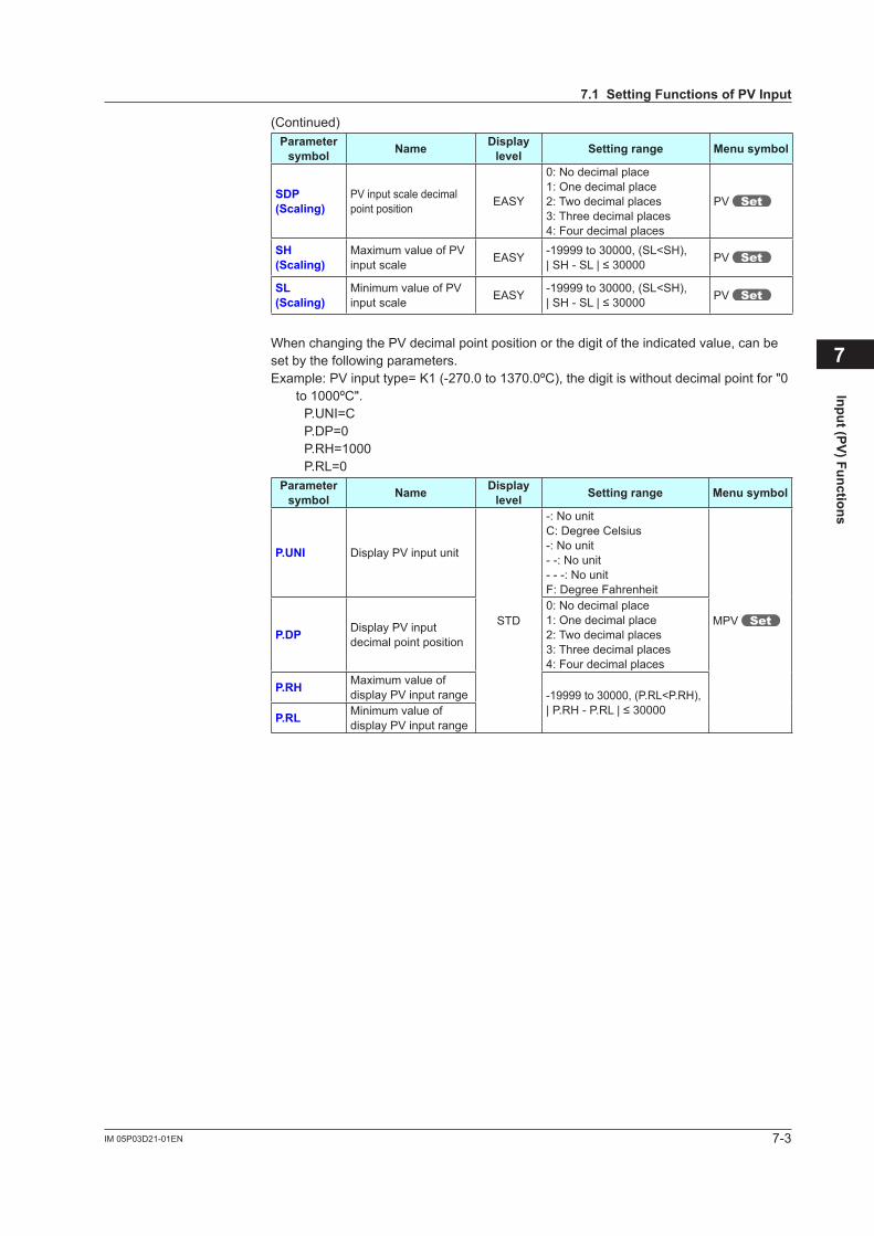
(Continued)Parameter
symbol Name Display level Setting range Menu symbol
SDP(Scaling)
PVinputscaledecimalpoint position EASY
0: No decimal place1: One decimal place2: Two decimal places3: Three decimal places4: Four decimal places
PV
SH(Scaling)
MaximumvalueofPVinput scale EASY -19999 to 30000, (SL<SH),
|SH-SL|≤30000 PV
SL (Scaling)
MinimumvalueofPVinput scale EASY -19999 to 30000, (SL<SH),
|SH-SL|≤30000 PV
WhenchangingthePVdecimalpointpositionorthedigitoftheindicatedvalue,canbeset by the following parameters.Example:PVinputtype=K1(-270.0to1370.0ºC), the digit is without decimal point for "0
to 1000ºC".P.UNI=CP.DP=0P.RH=1000P.RL=0
Parameter symbol Name Display
level Setting range Menu symbol
P.UNI DisplayPVinputunit
STD
-: No unitC: Degree Celsius-: No unit- -: No unit- - -: No unitF: Degree Fahrenheit
MPVP.DP DisplayPVinput
decimal point position
0: No decimal place1: One decimal place2: Two decimal places3: Three decimal places4: Four decimal places
P.RH Maximum value of displayPVinputrange -19999 to 30000, (P.RL<P.RH),
|P.RH-P.RL|≤30000P.RL Minimum value of displayPVinputrange
7.1 Setting Functions of PV Input
ºC
7-4 IM 05P03D21-01EN
7.1.2 Setting Burnout Detection for Input
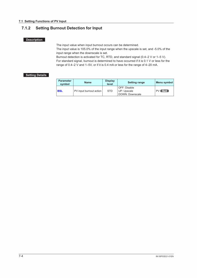
Description
The input value when input burnout occurs can be determined.Theinputvalueis105.0%oftheinputrangewhentheupscaleisset,and-5.0%oftheinput range when the downscale is set.BurnoutdetectionisactivatedforTC,RTD,andstandardsignal(0.4–2Vor1–5V).Forstandardsignal,burnoutisdeterminedtohaveoccurredifitis0.1Vorlessfortherangeof0.4–2Vand1–5V,orifitis0.4mAorlessfortherangeof4–20mA.
Setting Details
Parameter symbol Name Display
level Setting range Menu symbol
BSL PVinputburnoutaction STDOFF: DisableUP: UpscaleDOWN: Downscale
PV
7.1 Setting Functions of PV Input
7-5IM 05P03D21-01EN
Input (PV) Functions
7
7.1.3 Setting Reference Junction Compensation (RJC) or External Reference Junction Compensation (ERJC)
Description
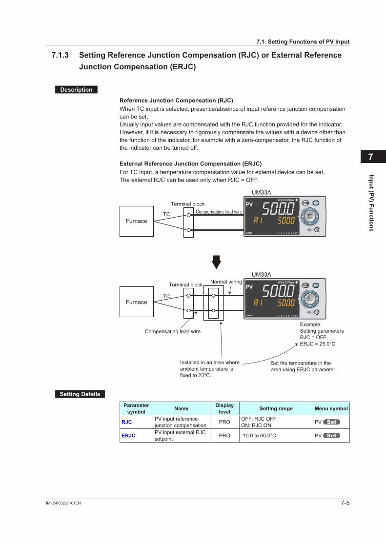
Reference Junction Compensation (RJC)WhenTCinputisselected,presence/absenceofinputreferencejunctioncompensationcan be set.Usually input values are compensated with the RJC function provided for the indicator. However, if it is necessary to rigorously compensate the values with a device other than the function of the indicator, for example with a zero-compensator, the RJC function of the indicator can be turned off.
External Reference Junction Compensation (ERJC)For TC input, a temperature compensation value for external device can be set.The external RJC can be used only when RJC = OFF.
8
8
Furnace
Furnace
UM33A
UM33A
Compensating lead wire
Compensating lead wire
Terminal block
Terminal block
TC
TC
Installed in an area where ambient temperature is fixed to 25°C.
Set the temperature in the area using ERJC parameter.
Normal wiring
Example:Setting parametersRJC = OFF,ERJC = 25.0°C
Setting Details
Parameter symbol Name Display
level Setting range Menu symbol
RJC PVinputreferencejunctioncompensation PRO OFF: RJC OFF
ON: RJC ON PV
ERJC PVinputexternalRJCsetpoint PRO -10.0to60.0°C PV
7.1 Setting Functions of PV Input
7-6 IM 05P03D21-01EN
7.1.4 Correcting Input Value
(1) Setting Bias and Filter
Description
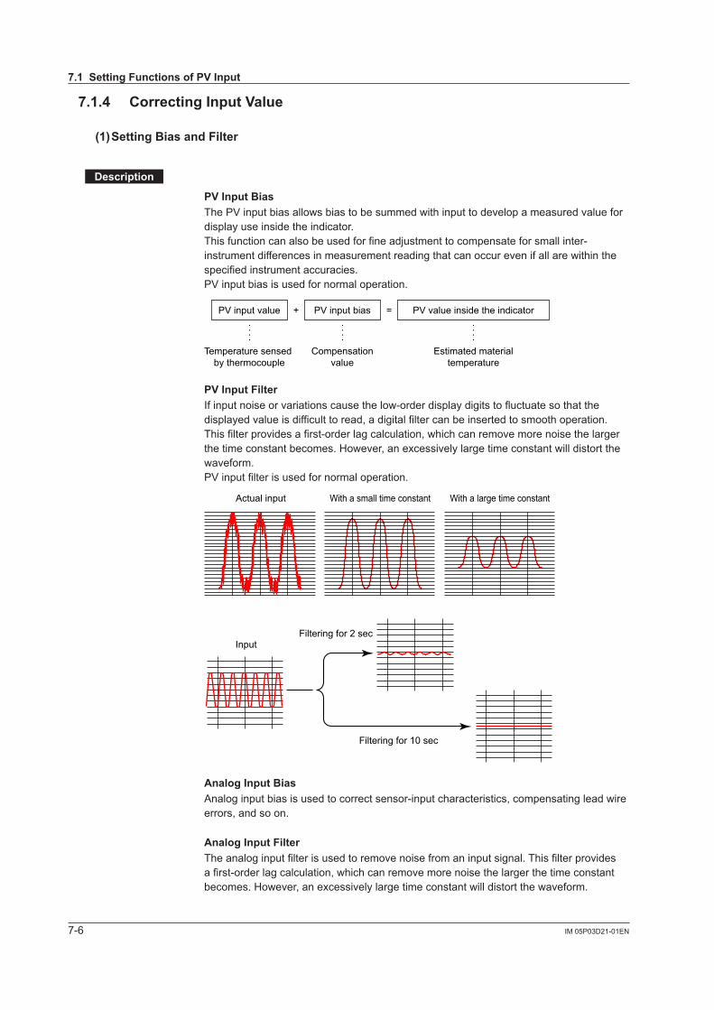
PV Input BiasThePVinputbiasallowsbiastobesummedwithinputtodevelopameasuredvaluefordisplay use inside the indicator.Thisfunctioncanalsobeusedforfineadjustmenttocompensateforsmallinter-instrument differences in measurement reading that can occur even if all are within the specified instrument accuracies.PVinputbiasisusedfornormaloperation.
PV input value + =PV input bias PV value inside the indicator
Temperature sensed by thermocouple
Compensationvalue
Estimated materialtemperature
PV Input FilterIf input noise or variations cause the low-order display digits to fluctuate so that the displayed value is difficult to read, a digital filter can be inserted to smooth operation. This filter provides a first-order lag calculation, which can remove more noise the larger the time constant becomes. However, an excessively large time constant will distort the waveform.PVinputfilterisusedfornormaloperation.
Actual input With a small time constant With a large time constant
InputFiltering for 2 sec
Filtering for 10 sec
Analog Input BiasAnalog input bias is used to correct sensor-input characteristics, compensating lead wire errors, and so on.
Analog Input FilterThe analog input filter is used to remove noise from an input signal. This filter provides a first-order lag calculation, which can remove more noise the larger the time constant becomes. However, an excessively large time constant will distort the waveform.
7.1 Setting Functions of PV Input
7-7IM 05P03D21-01EN
Input (PV) Functions
7
Setting Details
Parameter symbol Name Display
level Setting range Menu symbol
BS PVinputbias EASY -100.0to100.0%ofPVinput range span (EUS) PVS
FL PVinputfilter EASY OFF, 1 to 120 s
Parameter symbol Name Display
level Setting range Menu symbol
A.BS PVanaloginputbias STD -100.0to100.0%ofeachinput range span (EUS) PV
A.FL PVanaloginputfilter STD OFF, 1 to 120 s PV
(2) Setting Square Root Extraction and Low Signal Cutoff Point
Description
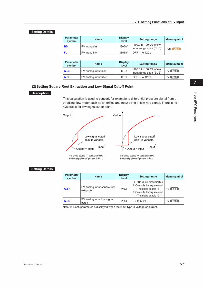
This calculation is used to convert, for example, a differential pressure signal from a throttling flow meter such as an orifice and nozzle into a flow-rate signal. There is no hysteresis for low signal cutoff point.
Output = Input
The slope equals “1” at levels below the low signal cutoff point (A.SR=1).
The slope equals “0” at levels belowthe low signal cutoff point (A.SR=2).
Output
Input Output = Input
Output
Input
Low signal cutoff point is variable.
Low signal cutoff point is variable.
Setting Details
Parameter symbol Name Display
level Setting range Menu symbol
A.SR PVanaloginputsquarerootextraction PRO
OFF: No square root extraction.1: Compute the square root.
(The slope equals “1.”)2: Compute the square root.
(The slope equals “0.”)
PV
A.LC PVanaloginputlowsignalcutoff PRO 0.0to5.0% PV
Note 1: Each parameter is displayed when the input type is voltage or current.
7.1 Setting Functions of PV Input
7-8 IM 05P03D21-01EN
(3) Setting 10-segment Linearizer
Description
The10-segmentlinearizercanbeusedforPVinputandretransmissionoutput. Function block diagram: 8.1 Function block diagram Output Linearizer: 10.2 Setting 10-segment Linearizer for Output
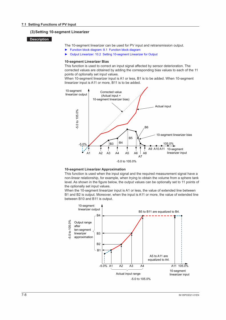
10-segment Linearizer BiasThis function is used to correct an input signal affected by sensor deterioration. The corrected values are obtained by adding the corresponding bias values to each of the 11 points of optionally set input values.When 10-segment linearizer input is A1 or less, B1 is to be added. When 10-segment linearizer input is A11 or more, B11 is to be added.
A1 A2 A3 A4 A5 A6A7
A8A9 A10 A11
B3 B4B5
B6
-5.0 to 105.0%
-5.0
to 1
05.0
%
-5.0% 105.0%
Corrected value(Actual input +
10-segment linearizer bias)
10-segmentlinearizer output
Actual input
10-segment linearizer bias
10-segmentlinearizer input
10-segment Linearizer ApproximationThis function is used when the input signal and the required measurement signal have a non-linear relationship, for example, when trying to obtain the volume from a sphere tank level. As shown in the figure below, the output values can be optionally set to 11 points of the optionally set input values.When the 10-segment linearizer input is A1 or less, the value of extended line between B1 and B2 is output. Moreover, when the input is A11 or more, the value of extended line between B10 and B11 is output.
-5.0 to 105.0%
-5.0 to 1
05.0
%
B1
A1 A2 A3 A4 A11 105.0%-5.0%
B2
B3
B4
Output rangeafterten-segmentlinearizerapproximation
10-segmentlinearizer output
Actual input range
B5 to B11 are equalized to B4.
A5 to A11 areequalized to A4.
10-segmentlinearizer input
7.1 Setting Functions of PV Input
7-9IM 05P03D21-01EN
Input (PV) Functions
7
Setting Details
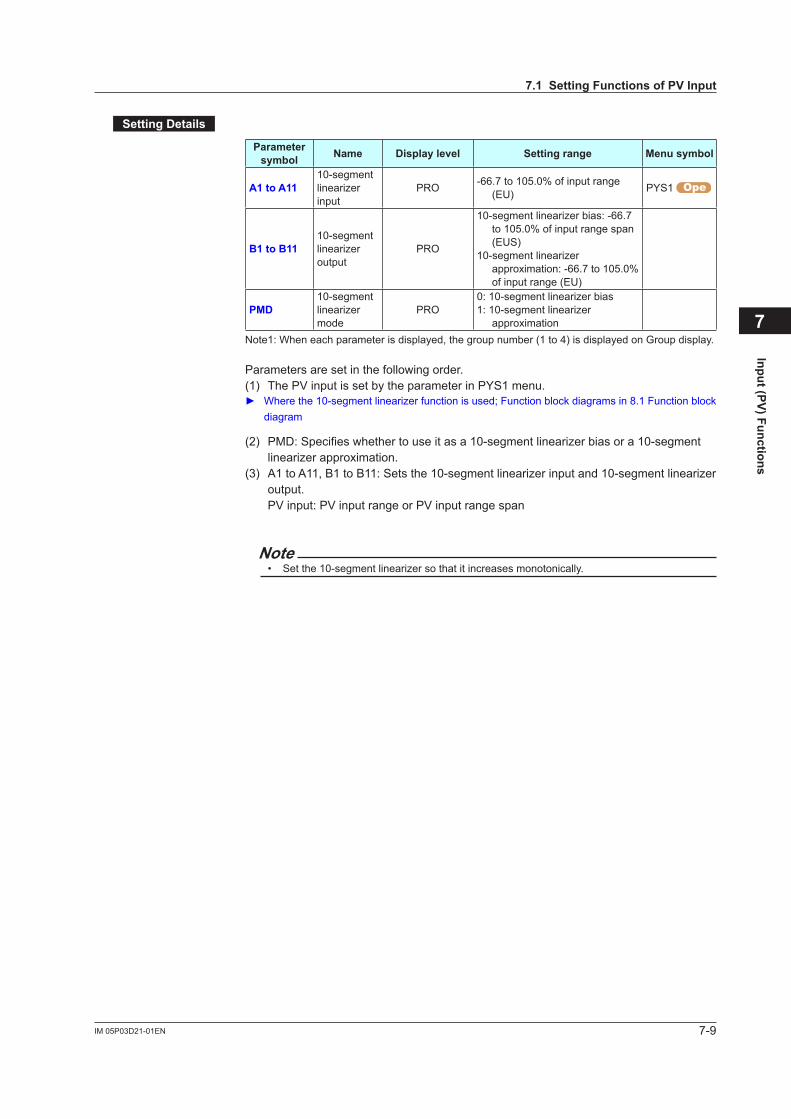
Parameter symbol Name Display level Setting range Menu symbol
A1 to A1110-segment linearizer input
PRO -66.7to105.0%ofinputrange(EU) PYS1
B1 to B1110-segment linearizer output
PRO
10-segment linearizer bias: -66.7 to105.0%ofinputrangespan(EUS)
10-segment linearizer approximation:-66.7to105.0%of input range (EU)
PMD10-segment linearizer mode
PRO0: 10-segment linearizer bias1: 10-segment linearizer
approximationNote1: When each parameter is displayed, the group number (1 to 4) is displayed on Group display.
Parameters are set in the following order.(1) ThePVinputissetbytheparameterinPYS1menu. Where the 10-segment linearizer function is used; Function block diagrams in 8.1 Function block
diagram
(2) PMD: Specifies whether to use it as a 10-segment linearizer bias or a 10-segment linearizer approximation.
(3) A1 to A11, B1 to B11: Sets the 10-segment linearizer input and 10-segment linearizer output. PVinput:PVinputrangeorPVinputrangespan
Note• Set the 10-segment linearizer so that it increases monotonically.
7.1 Setting Functions of PV Input
7-10 IM 05P03D21-01EN
7.2 Setting Input Sampling Period
Setting Details
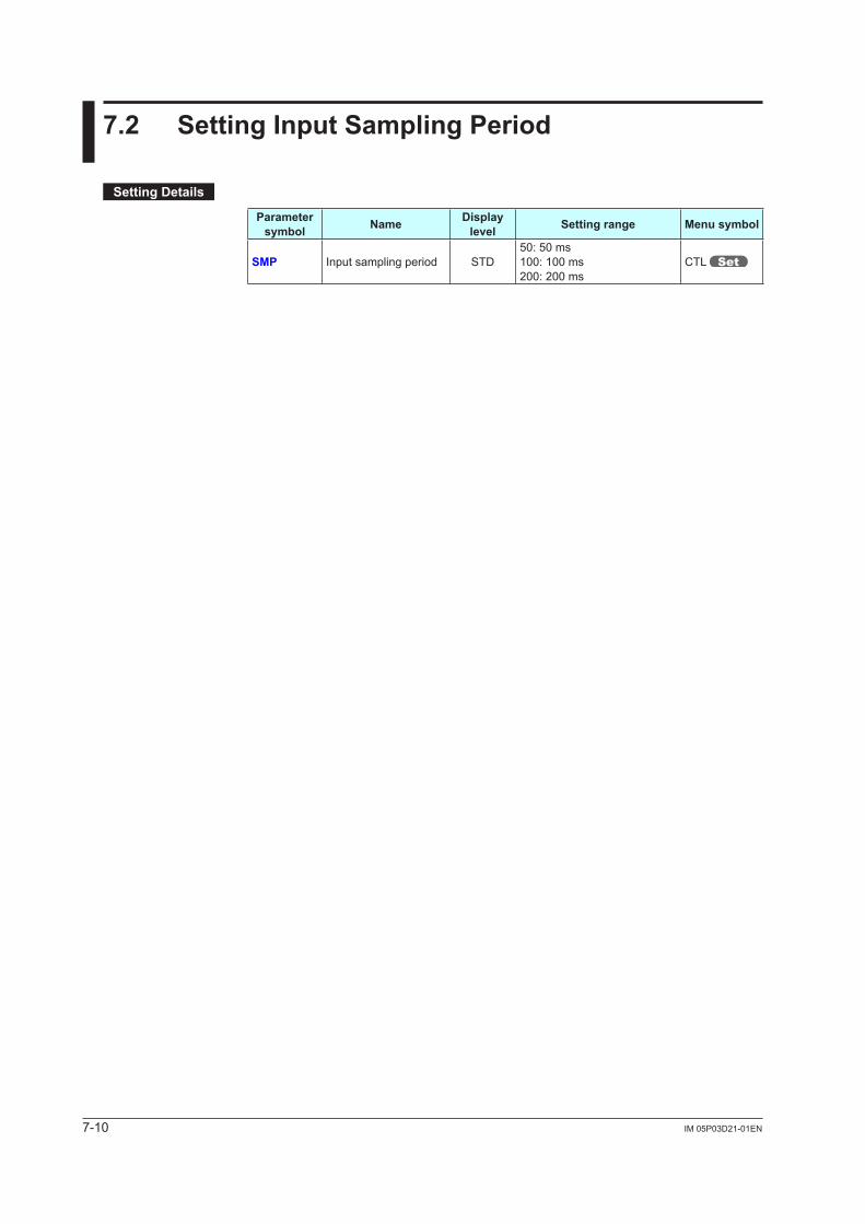
Parameter symbol Name Display
level Setting range Menu symbol
SMP Input sampling period STD50: 50 ms100: 100 ms200: 200 ms
CTL
8-1IM 05P03D21-01EN
Functions
8
8.1 Function Block Diagrams
Description
The Function block diagram describes only the basic functions.Parameter symbols in the Function block diagram describe representative parameters.
For the functions and parameters which are not described in Function block diagram, see the following. Contactinputassignment:11.1SettingContactInputFunction Contactoutputassignment:11.2SettingContactOutputFunction Analogoutputrangechange:10.3ChangingCurrentOutputRange
Chapter 8 Functions

8-2 IM 05P03D21-01EN
8.1 Function Block Diagrams
BS
FL
LAT
RST
PEAK BOTM
PMD An, Bn
UNIT
IN
RH, RL SDP SH, SL
A.SR
A.BS
A.FL
RTS
RET.H RET.L
PMD An, Bn
A.LC
Input type
PV analog input bias
Square root extraction
PV analog input filter
10-seg. linearizer approx./bias
10-seg. linearizer approx./bias
PV peak and bottom value
Input unit
Input range/scale
PV input bias
PV input filter
Equipped as standard Equipped as standard For suffix code: Type2=3
RelayAlarm 4
(PV low limit)
24 V looppower supply
Current
For optional suffix code /LP
RET retransmission output Alarm Contact outputContact output
Alarm processing
Contact inputs
PV
PV input
Equipped as standard Equipped as standard.
Ala
rm 1
(PV
hig
h lim
it)
Ala
rm 2
(PV
low
lim
it)
Ala
rm 3
(PV
hig
h lim
it)
Ala
rm 5
(PV
hig
h lim
it)
Ala
rm 6
(PV
low
lim
it)
Ala
rm 8
(PV
low
lim
it)
Ala
rm 7
(PV
hig
h lim
it)
PV display
Com.
AL4LPS
DI2DI1
RET AL3AL2AL1 DO13DO12DO11 DO14 DO15
FAIL
RS-485
Terminal Parameter Function
Analog signal Contact signal Front panel keyLegend
DI1=ON: PV peak and bottom values reset
OFF → ON: Latch release
Split computation
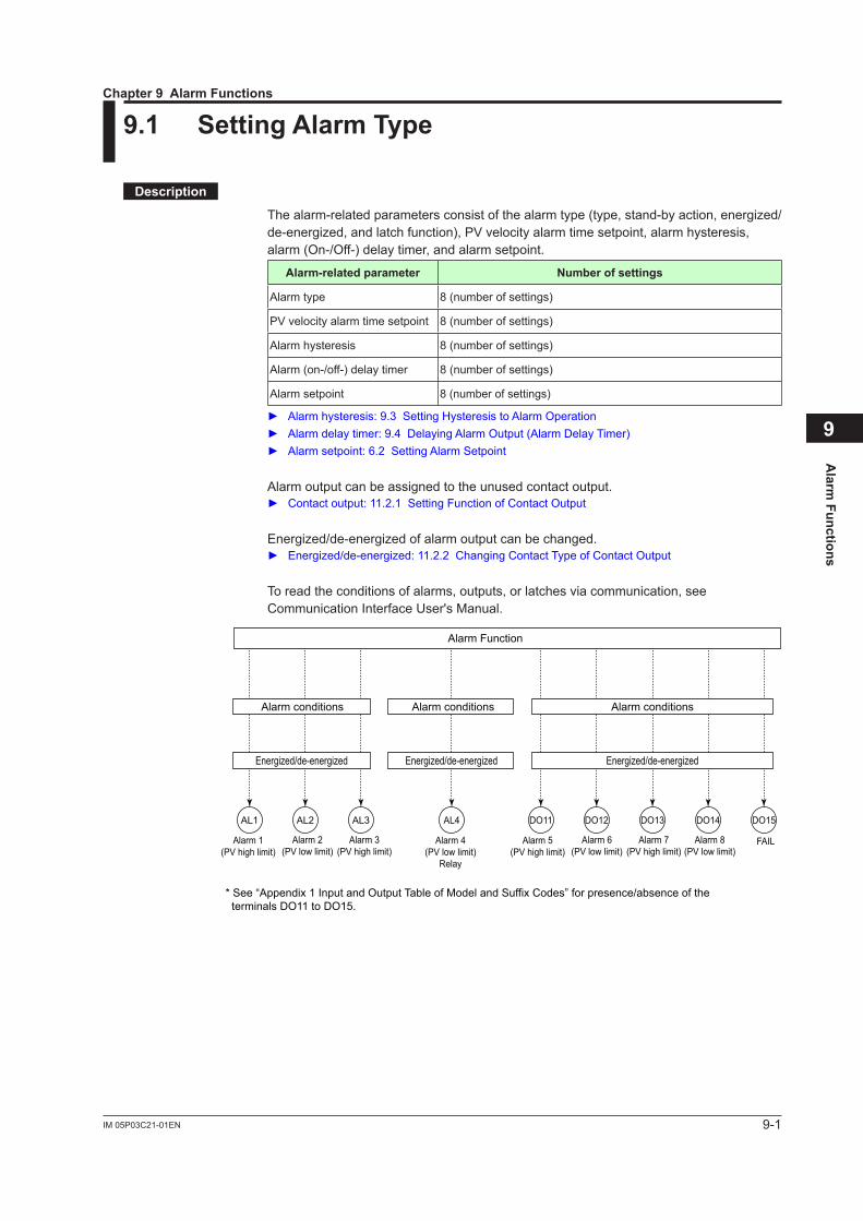
9-1IM 05P03C21-01EN
Alarm
Functions
9
9.1 Setting Alarm Type
Description
The alarm-related parameters consist of the alarm type (type, stand-by action, energized/de-energized,andlatchfunction),PVvelocityalarmtimesetpoint,alarmhysteresis,alarm (On-/Off-) delay timer, and alarm setpoint.
Alarm-related parameter Number of settings
Alarm type 8 (number of settings)
PVvelocityalarmtimesetpoint 8 (number of settings)
Alarm hysteresis 8 (number of settings)
Alarm (on-/off-) delay timer 8 (number of settings)
Alarm setpoint 8 (number of settings)
Alarmhysteresis:9.3SettingHysteresistoAlarmOperation Alarmdelaytimer:9.4DelayingAlarmOutput(AlarmDelayTimer) Alarmsetpoint:6.2SettingAlarmSetpoint
Alarm output can be assigned to the unused contact output. Contactoutput:11.2.1SettingFunctionofContactOutput
Energized/de-energized of alarm output can be changed. Energized/de-energized:11.2.2ChangingContactTypeofContactOutput
To read the conditions of alarms, outputs, or latches via communication, see Communication Interface User's Manual.
AL3AL2AL1 AL4 DO12DO11 DO15DO14DO13
* See “Appendix 1 Input and Output Table of Model and Suffix Codes” for presence/absence of the terminals DO11 to DO15.
Alarm conditions Alarm conditions Alarm conditions
Energized/de-energized Energized/de-energized Energized/de-energized
Alarm 1(PV high limit)
Alarm 2(PV low limit)
Alarm 3(PV high limit)
Alarm 5(PV high limit)
Alarm 6(PV low limit)
Alarm 8(PV low limit)
Alarm 7(PV high limit)
Alarm 4(PV low limit)
Relay
FAIL
Alarm Function
Chapter 9 Alarm Functions
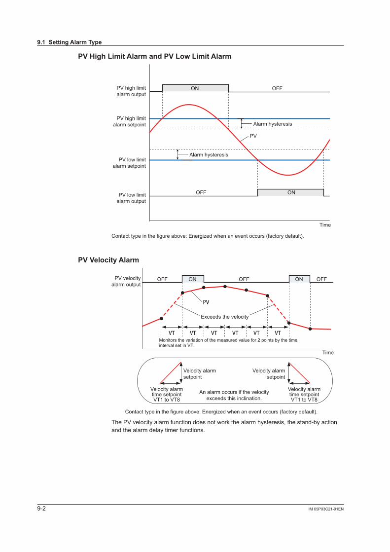
9-2 IM 05P03C21-01EN
PV High Limit Alarm and PV Low Limit Alarm
PV
ON OFF
ON
Contact type in the figure above: Energized when an event occurs (factory default).
Alarm hysteresis
Alarm hysteresis
OFF
Time
PV high limitalarm setpoint
PV low limitalarm setpoint
PV high limitalarm output
PV low limitalarm output
PV Velocity Alarm
PV
VT VT VT VT VT VT
PV velocityalarm output
Time
An alarm occurs if the velocityexceeds this inclination.
OFF OFF OFFON ON
Velocity alarmtime setpointVT1 to VT8
Velocity alarmsetpoint
Velocity alarmsetpoint
Velocity alarmtime setpointVT1 to VT8
Exceeds the velocity
Contact type in the figure above: Energized when an event occurs (factory default).
Monitors the variation of the measured value for 2 points by the time interval set in VT.
ThePVvelocityalarmfunctiondoesnotworkthealarmhysteresis,thestand-byactionand the alarm delay timer functions.
9.1 Setting Alarm Type
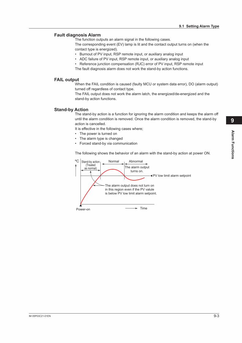
9-3IM 05P03C21-01EN
Alarm
Functions
9
Fault diagnosis AlarmThe function outputs an alarm signal in the following cases.Thecorrespondingevent(EV)lampislitandthecontactoutputturnson(whenthecontact type is energized).• BurnoutofPVinput,RSPremoteinput,orauxiliaryanaloginput• ADC failure ofPVinput,RSPremoteinput,orauxiliaryanaloginput• Referencejunctioncompensation(RJC)errorofPVinput,RSPremoteinputThe fault diagnosis alarm does not work the stand-by action functions.
FAIL outputWhen the FAIL condition is caused (faulty MCU or system data error), DO (alarm output) turned off regardless of contact type.The FAIL output does not work the alarm latch, the energized/de-energized and the stand-by action functions.
Stand-by ActionThe stand-by action is a function for ignoring the alarm condition and keeps the alarm off until the alarm condition is removed. Once the alarm condition is removed, the stand-by action is cancelled. It is effective in the following cases where;• The power is turned on• The alarm type is changed• Forced stand-by via communication
The following shows the behavior of an alarm with the stand-by action at power ON.
Stand-by action(Treated
as normal)
ºC
Power-on Time
The alarm output does not turn onin this region even if the PV valuleis below PV low limit alarm setpoint.
PV low limit alarm setpoint
Normal Abnormal
The alarm outputturns on.
9.1 Setting Alarm Type
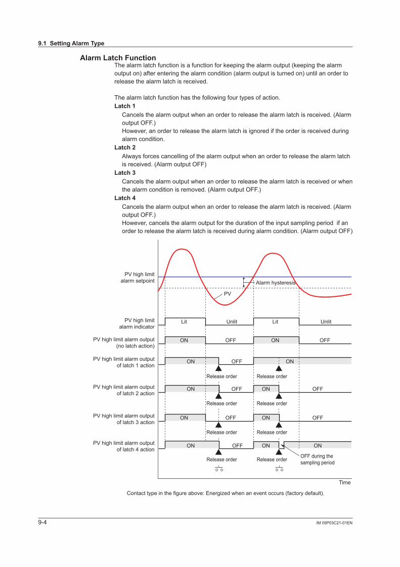
9-4 IM 05P03C21-01EN
Alarm Latch FunctionThe alarm latch function is a function for keeping the alarm output (keeping the alarm output on) after entering the alarm condition (alarm output is turned on) until an order to release the alarm latch is received.
The alarm latch function has the following four types of action. Latch 1 Cancels the alarm output when an order to release the alarm latch is received. (Alarm
output OFF.) However, an order to release the alarm latch is ignored if the order is received during alarm condition.
Latch 2 Always forces cancelling of the alarm output when an order to release the alarm latch
is received. (Alarm output OFF)Latch 3 Cancels the alarm output when an order to release the alarm latch is received or when
the alarm condition is removed. (Alarm output OFF.)Latch 4 Cancels the alarm output when an order to release the alarm latch is received. (Alarm
output OFF.) However, cancels the alarm output for the duration of the input sampling period if an order to release the alarm latch is received during alarm condition. (Alarm output OFF)
PV
Lit Lit
Contact type in the figure above: Energized when an event occurs (factory default).
Alarm hysteresis
Unlit Unlit
ON
ON ON
ONOFF
OFF
OFF
ON ONOFF OFF
Time
PV high limitalarm setpoint
PV high limitalarm indicator
PV high limit alarm output(no latch action)
PV high limit alarm outputof latch 1 action
PV high limit alarm outputof latch 2 action
ON ONOFF OFFPV high limit alarm outputof latch 3 action
ON ON ON
OFF during the sampling period
OFFPV high limit alarm outputof latch 4 action
Release order Release order
Release order Release order
Release order
Release order
Release order
Release order
9.1 Setting Alarm Type
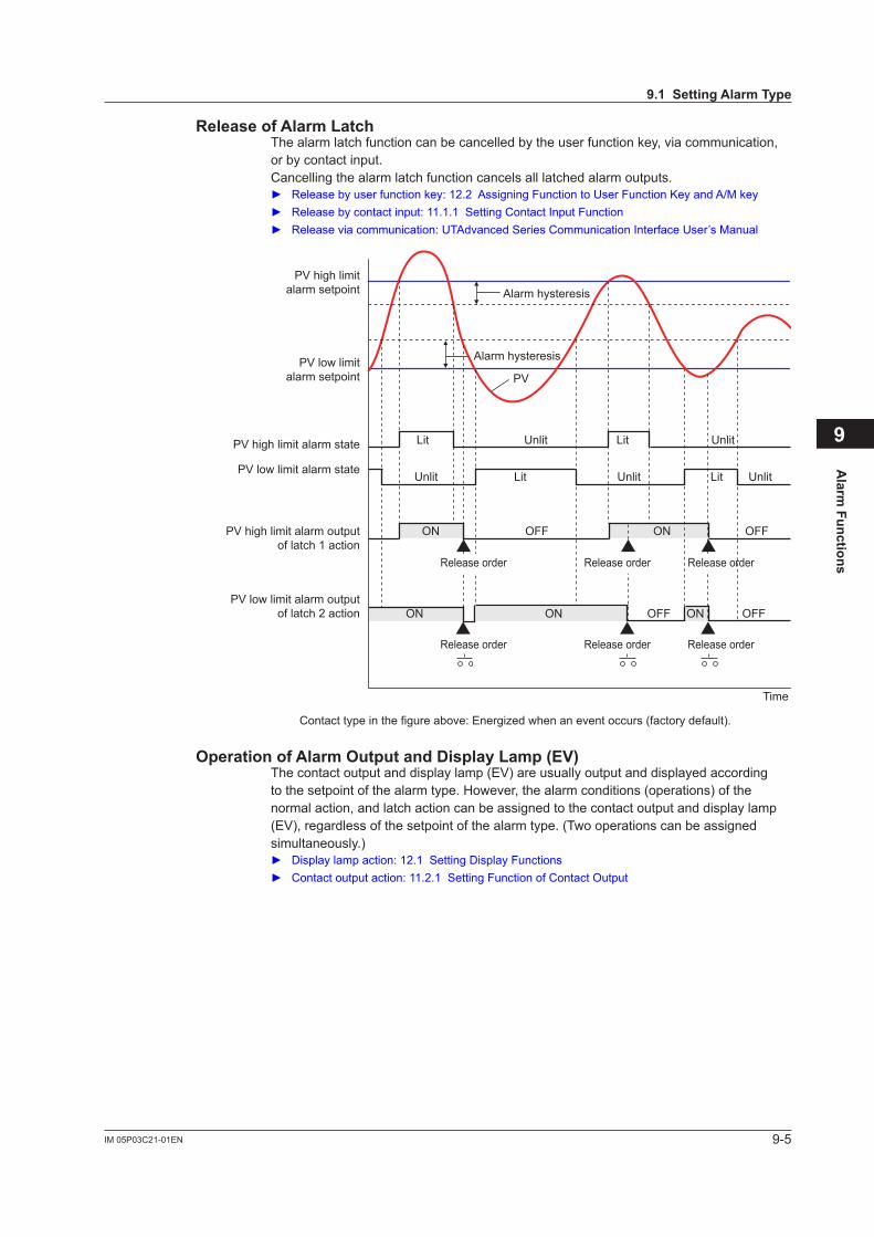
9-5IM 05P03C21-01EN
Alarm
Functions
9
Release of Alarm LatchThe alarm latch function can be cancelled by the user function key, via communication, or by contact input.Cancelling the alarm latch function cancels all latched alarm outputs. Releasebyuserfunctionkey:12.2AssigningFunctiontoUserFunctionKeyandA/Mkey Releasebycontactinput:11.1.1SettingContactInputFunction Releaseviacommunication:UTAdvancedSeriesCommunicationInterfaceUser’sManual
PV
Lit Lit
Contact type in the figure above: Energized when an event occurs (factory default).
Alarm hysteresis
Alarm hysteresis
Unlit Unlit
Lit LitUnlit Unlit Unlit
ON ONOFF OFF
ON ON ONOFF OFF
Time
PV high limitalarm setpoint
PV low limitalarm setpoint
PV high limit alarm state
PV low limit alarm state
PV high limit alarm outputof latch 1 action
PV low limit alarm outputof latch 2 action
Release order Release order Release order
Release order Release order Release order
Operation of Alarm Output and Display Lamp (EV)Thecontactoutputanddisplaylamp(EV)areusuallyoutputanddisplayedaccordingto the setpoint of the alarm type. However, the alarm conditions (operations) of the normal action, and latch action can be assigned to the contact output and display lamp (EV),regardlessofthesetpointofthealarmtype.(Twooperationscanbeassignedsimultaneously.) Displaylampaction:12.1SettingDisplayFunctions Contactoutputaction:11.2.1SettingFunctionofContactOutput
9.1 Setting Alarm Type
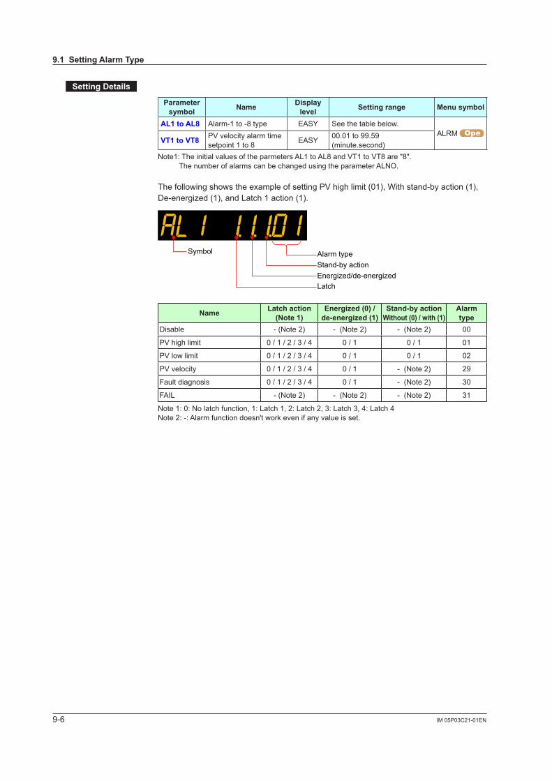
9-6 IM 05P03C21-01EN
Setting Details
Parameter symbol Name Display
level Setting range Menu symbol
AL1 to AL8 Alarm-1 to -8 type EASY See the table below.ALRM
VT1 to VT8 PVvelocityalarmtimesetpoint 1 to 8 EASY 00.01 to 99.59
(minute.second)Note1:TheinitialvaluesoftheparmetersAL1toAL8andVT1toVT8are"8".
The number of alarms can be changed using the parameter ALNO.
ThefollowingshowstheexampleofsettingPVhighlimit(01),Withstand-byaction(1),De-energized (1), and Latch 1 action (1).
Alarm typeSymbol
Stand-by actionEnergized/de-energizedLatch
Name Latch action (Note 1)
Energized (0) / de-energized (1)
Stand-by actionWithout (0) / with (1)
Alarm type
Disable - (Note 2) - (Note 2) - (Note 2) 00
PVhighlimit 0 / 1 / 2 / 3 / 4 0 / 1 0 / 1 01
PVlowlimit 0 / 1 / 2 / 3 / 4 0 / 1 0 / 1 02
PVvelocity 0 / 1 / 2 / 3 / 4 0 / 1 - (Note 2) 29
Fault diagnosis 0 / 1 / 2 / 3 / 4 0 / 1 - (Note 2) 30
FAIL - (Note 2) - (Note 2) - (Note 2) 31
Note 1: 0: No latch function, 1: Latch 1, 2: Latch 2, 3: Latch 3, 4: Latch 4Note 2: -: Alarm function doesn't work even if any value is set.
9.1 Setting Alarm Type
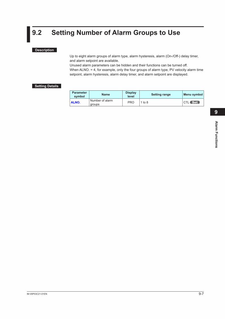
9-7IM 05P03C21-01EN
Alarm
Functions
9
9.2 Setting Number of Alarm Groups to Use
Description
Up to eight alarm groups of alarm type, alarm hysteresis, alarm (On-/Off-) delay timer, and alarm setpoint are available.Unused alarm parameters can be hidden and their functions can be turned off. WhenALNO.=4,forexample,onlythefourgroupsofalarmtype,PVvelocityalarmtimesetpoint, alarm hysteresis, alarm delay timer, and alarm setpoint are displayed.
Setting Details
Parameter symbol Name Display
level Setting range Menu symbol
ALNO. Number of alarm groups PRO 1 to 8 CTL
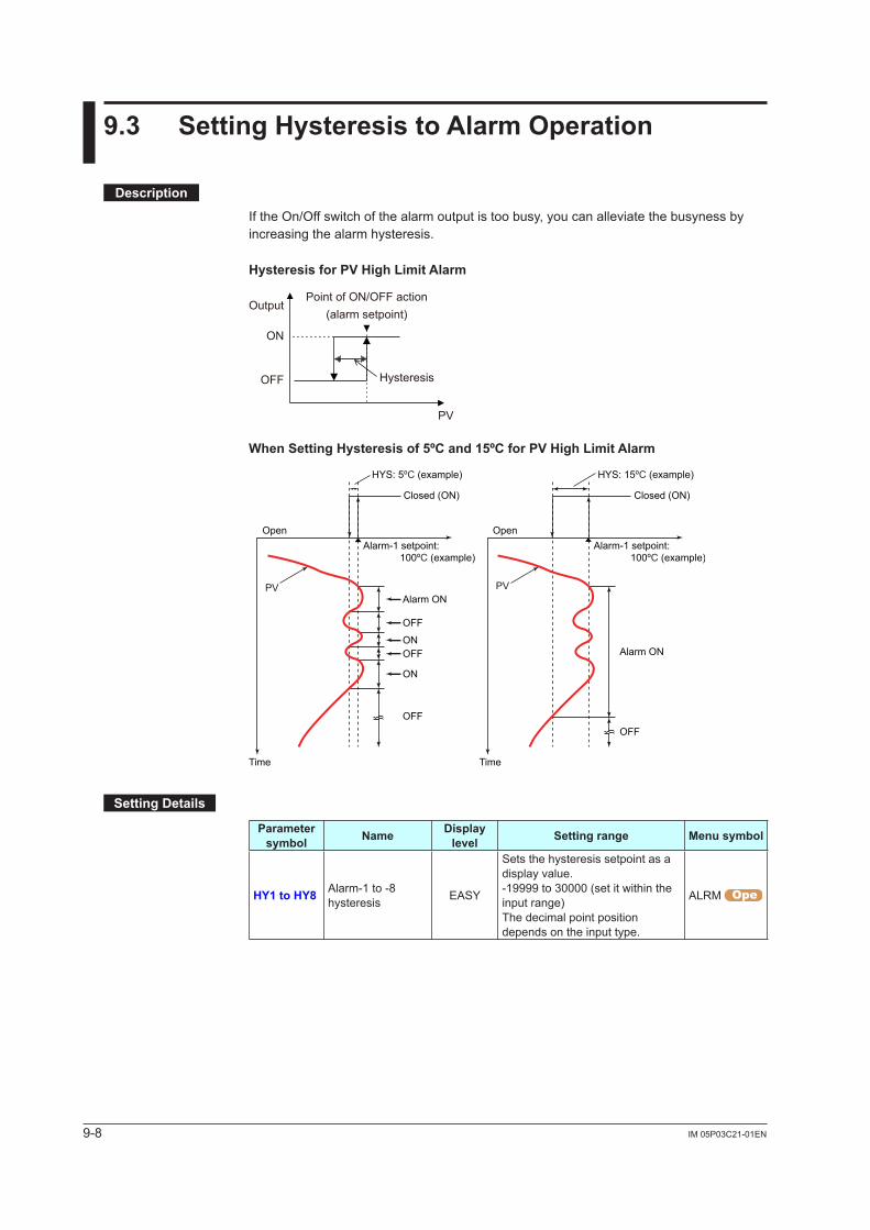
9-8 IM 05P03C21-01EN
9.3 Setting Hysteresis to Alarm Operation
Description
If the On/Off switch of the alarm output is too busy, you can alleviate the busyness by increasing the alarm hysteresis.
Hysteresis for PV High Limit Alarm
Point of ON/OFF action(alarm setpoint)
PV
Output
ON
OFF Hysteresis
When Setting Hysteresis of 5ºC and 15ºC for PV High Limit Alarm
Closed (ON)
Open
Time
Alarm-1 setpoint: 100ºC (example)
Closed (ON)
Open
Time
Alarm-1 setpoint: 100ºC (example)
HYS: 15ºC (example)HYS: 5ºC (example)
PV PVAlarm ON
OFF
ONOFF
ON
OFF
Alarm ON
OFF
Setting Details
Parameter symbol Name Display
level Setting range Menu symbol
HY1 to HY8 Alarm-1 to -8 hysteresis EASY
Sets the hysteresis setpoint as a display value.-19999 to 30000 (set it within the input range)The decimal point position depends on the input type.
ALRM
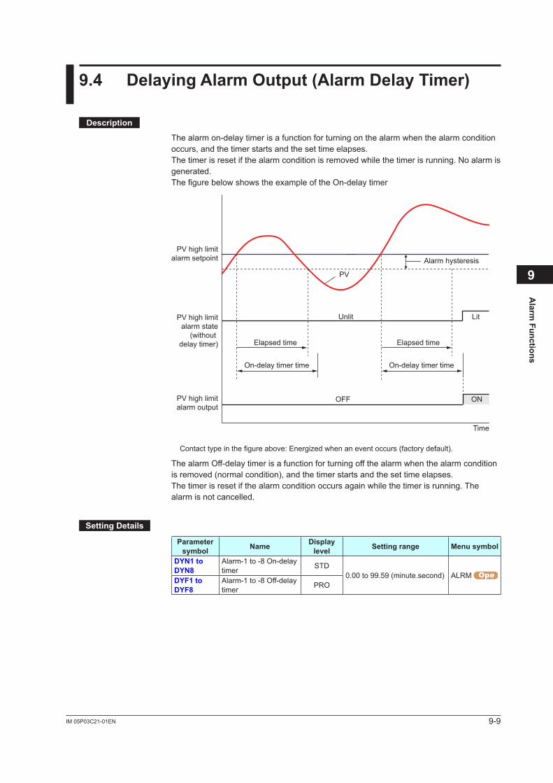
9-9IM 05P03C21-01EN
Alarm
Functions
9
9.4 Delaying Alarm Output (Alarm Delay Timer)
Description
The alarm on-delay timer is a function for turning on the alarm when the alarm condition occurs, and the timer starts and the set time elapses.The timer is reset if the alarm condition is removed while the timer is running. No alarm is generated.The figure below shows the example of the On-delay timer
PV
Elapsed time
On-delay timer time
Lit
Contact type in the figure above: Energized when an event occurs (factory default).
Alarm hysteresis
Unlit
OFF
Time
PV high limitalarm setpoint
PV high limitalarm state
(withoutdelay timer)
PV high limitalarm output
Elapsed time
On-delay timer time
ON
The alarm Off-delay timer is a function for turning off the alarm when the alarm condition is removed (normal condition), and the timer starts and the set time elapses.The timer is reset if the alarm condition occurs again while the timer is running. The alarm is not cancelled.
Setting Details
Parameter symbol Name Display
level Setting range Menu symbol
DYN1 to DYN8
Alarm-1 to -8 On-delay timer STD
0.00 to 99.59 (minute.second) ALRM DYF1 to DYF8
Alarm-1 to -8 Off-delay timer PRO

Blank Page
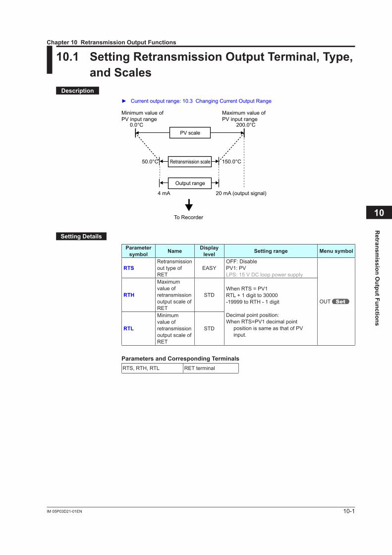
10-1IM 05P03D21-01EN
Retransm
ission Output Functions
10
10.1 Setting Retransmission Output Terminal, Type, and Scales
Description Currentoutputrange:10.3ChangingCurrentOutputRange
20 mA (output signal)
0.0°C 200.0°C
4 mA
50.0°C 150.0°CRetransmission scale
PV scale
Output range
Minimum value ofPV input range
Maximum value ofPV input range
To Recorder
Setting Details
Parameter symbol Name Display
level Setting range Menu symbol
RTSRetransmission out type of RET
EASYOFF: DisablePV1:PVLPS:15VDClooppowersupply
OUT RTH
Maximum value of retransmission output scale of RET
STDWhenRTS=PV1RTL + 1 digit to 30000-19999 to RTH - 1 digit
Decimal point position:WhenRTS=PV1decimalpoint
positionissameasthatofPVinput.
RTL
Minimum value of retransmission output scale of RET
STD
Parameters and Corresponding TerminalsRTS, RTH, RTL RET terminal
Chapter 10 Retransmission Output Functions
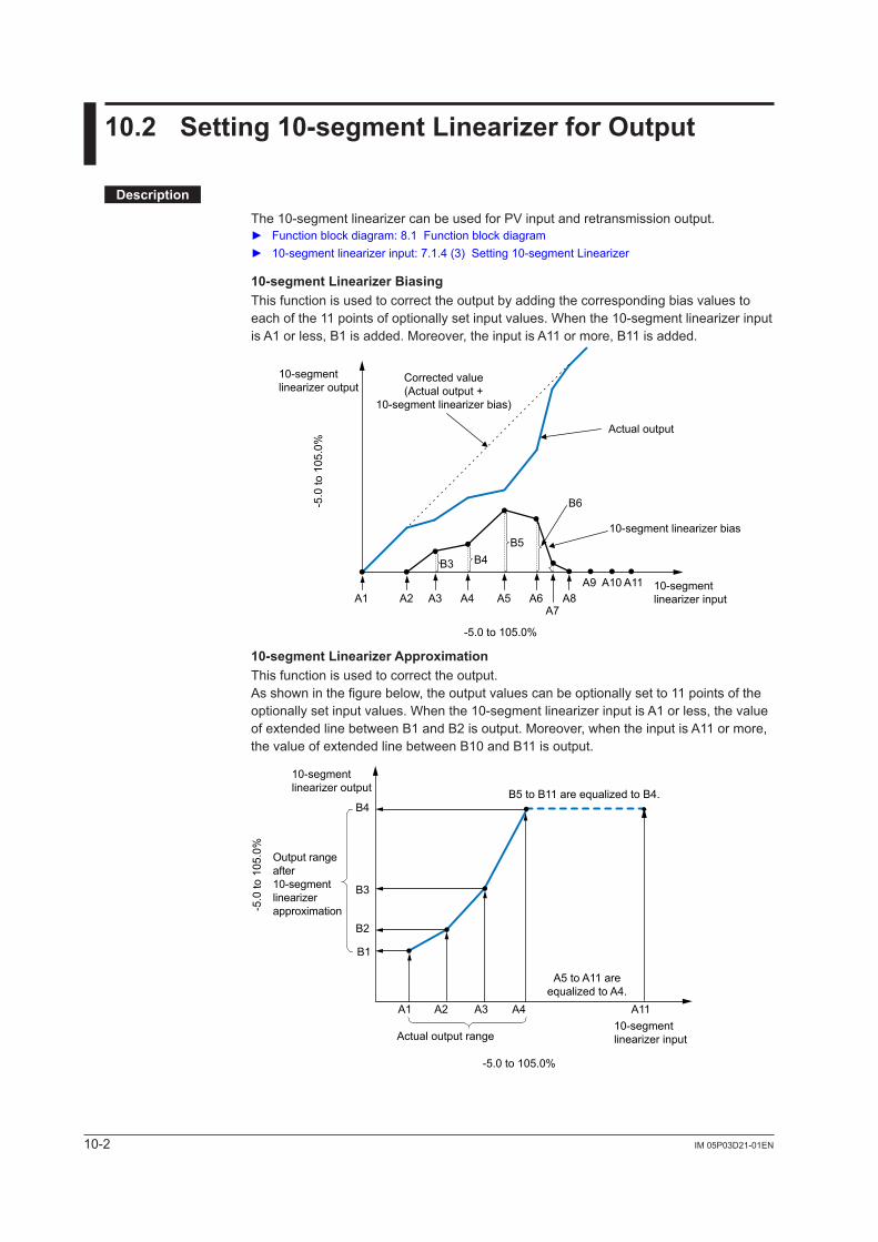
10-2 IM 05P03D21-01EN
10.2 Setting 10-segment Linearizer for Output
Description
The10-segmentlinearizercanbeusedforPVinputandretransmissionoutput. Function block diagram: 8.1 Function block diagram 10-segment linearizer input: 7.1.4 (3) Setting 10-segment Linearizer
10-segment Linearizer BiasingThis function is used to correct the output by adding the corresponding bias values to each of the 11 points of optionally set input values. When the 10-segment linearizer input is A1 or less, B1 is added. Moreover, the input is A11 or more, B11 is added.
A1 A2 A3 A4 A5 A6A7
A8A9 A10 A11
B3 B4B5
B6
10-segmentlinearizer input
Actual output
10-segment linearizer bias
Corrected value(Actual output +
10-segment linearizer bias)
10-segmentlinearizer output
-5.0 to 105.0%
-5.0
to 1
05.0
%
10-segment Linearizer ApproximationThis function is used to correct the output.As shown in the figure below, the output values can be optionally set to 11 points of the optionally set input values. When the 10-segment linearizer input is A1 or less, the value of extended line between B1 and B2 is output. Moreover, when the input is A11 or more, the value of extended line between B10 and B11 is output.
B1
A1 A2 A3 A4 A11
B2
B3
B4
-5.0 to 105.0%
-5.0
to 1
05.0
%
A5 to A11 areequalized to A4.
B5 to B11 are equalized to B4.
10-segmentlinearizer input
10-segmentlinearizer output
Actual output range
Output rangeafter10-segmentlinearizerapproximation
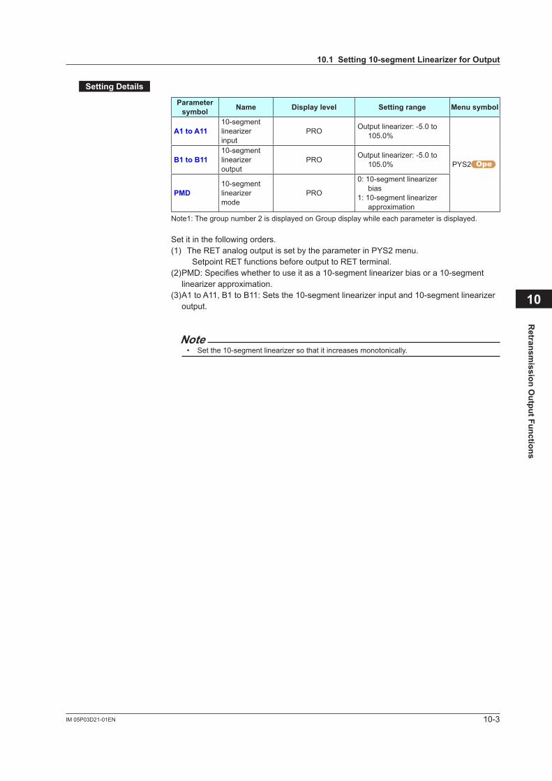
10-3IM 05P03D21-01EN
Retransm
ission Output Functions
10
Setting Details
Parameter symbol Name Display level Setting range Menu symbol
A1 to A1110-segment linearizerinput
PRO Output linearizer: -5.0 to 105.0%
PYS2B1 to B1110-segment linearizeroutput
PRO Output linearizer: -5.0 to 105.0%
PMD10-segment linearizer mode
PRO
0: 10-segment linearizer bias
1: 10-segment linearizer approximation
Note1: The group number 2 is displayed on Group display while each parameter is displayed.
Set it in the following orders.(1) The RET analog output is set by the parameter in PYS2 menu.
Setpoint RET functions before output to RET terminal.(2) PMD: Specifies whether to use it as a 10-segment linearizer bias or a 10-segment
linearizer approximation. (3) A1 to A11, B1 to B11: Sets the 10-segment linearizer input and 10-segment linearizer
output.
Note• Set the 10-segment linearizer so that it increases monotonically.
10.1 Setting 10-segment Linearizer for Output
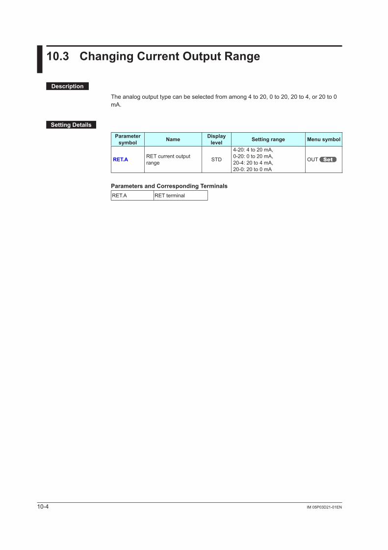
10-4 IM 05P03D21-01EN
10.3 Changing Current Output Range
Description
The analog output type can be selected from among 4 to 20, 0 to 20, 20 to 4, or 20 to 0 mA.
Setting Details
Parameter symbol Name Display
level Setting range Menu symbol
RET.A RET current output range STD
4-20: 4 to 20 mA,0-20: 0 to 20 mA,20-4: 20 to 4 mA,20-0: 20 to 0 mA
OUT
Parameters and Corresponding TerminalsRET.A RET terminal
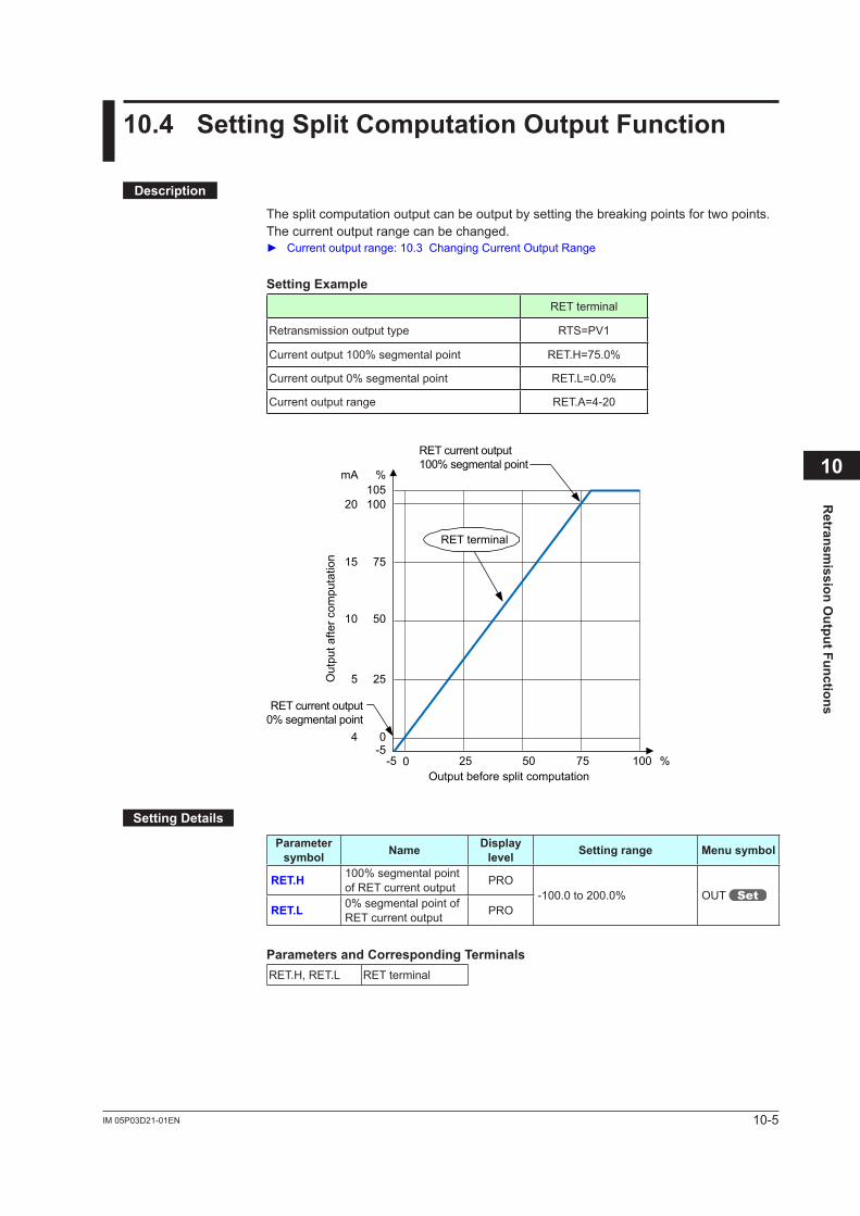
10-5IM 05P03D21-01EN
Retransm
ission Output Functions
10
10.4 Setting Split Computation Output Function
Description
The split computation output can be output by setting the breaking points for two points.The current output range can be changed. Current output range: 10.3 Changing Current Output Range
Setting ExampleRET terminal
Retransmission output type RTS=PV1
Currentoutput100%segmentalpoint RET.H=75.0%
Currentoutput0%segmentalpoint RET.L=0.0%
Current output range RET.A=4-20
Output before split computation
Out
put a
fter c
ompu
tatio
n
RET current output0% segmental point
RET current output100% segmental point
RET terminal
0 5025 75 100
25
50
75
100105
%
%
20
mA
4 0-5
-5
10
5
15
Setting Details
Parameter symbol Name Display
level Setting range Menu symbol
RET.H 100%segmentalpointof RET current output PRO
-100.0to200.0% OUT RET.L 0%segmentalpointof
RET current output PRO
Parameters and Corresponding TerminalsRET.H, RET.L RET terminal
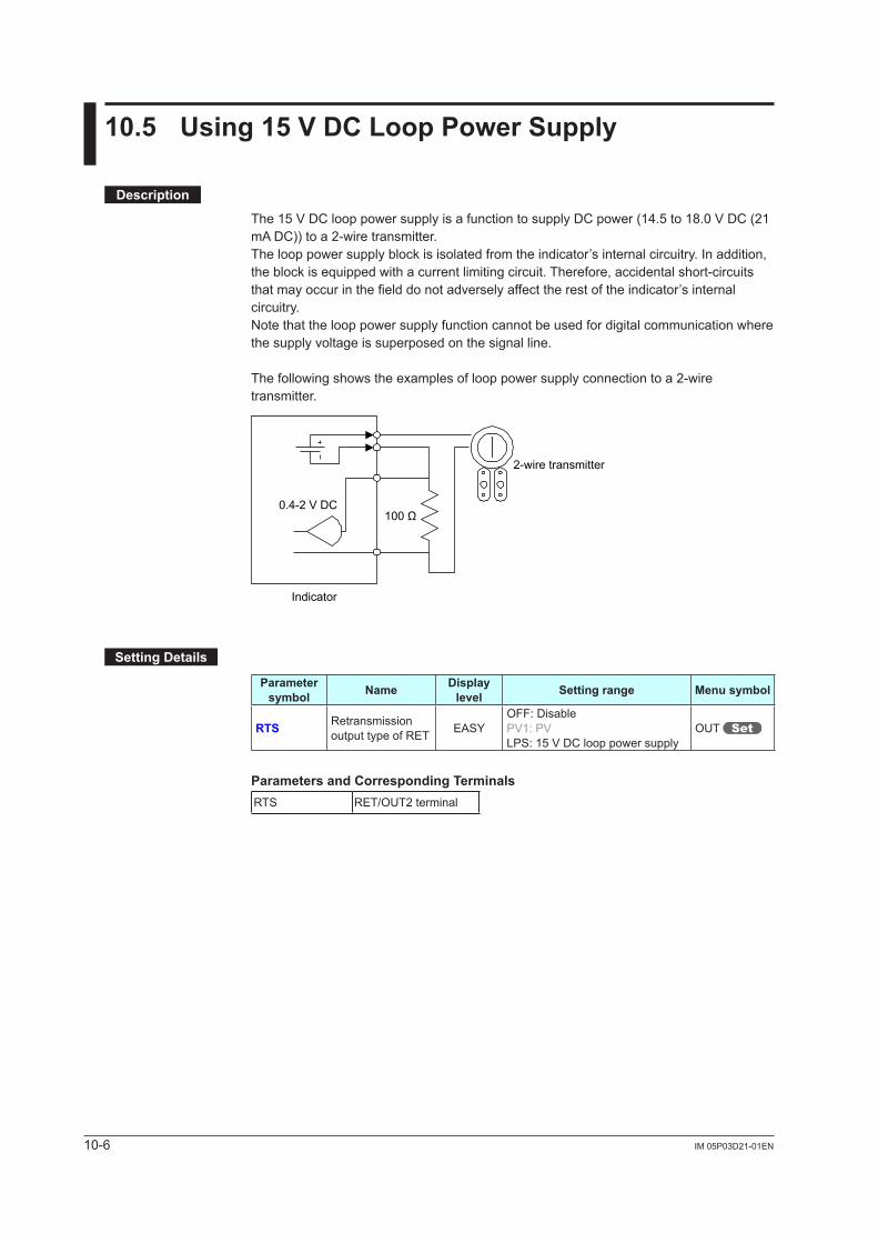
10-6 IM 05P03D21-01EN
10.5 Using 15 V DC Loop Power Supply
Description
The15VDClooppowersupplyisafunctiontosupplyDCpower(14.5to18.0VDC(21mA DC)) to a 2-wire transmitter.The loop power supply block is isolated from the indicator’s internal circuitry. In addition, the block is equipped with a current limiting circuit. Therefore, accidental short-circuits that may occur in the field do not adversely affect the rest of the indicator’s internal circuitry.Note that the loop power supply function cannot be used for digital communication where the supply voltage is superposed on the signal line.
The following shows the examples of loop power supply connection to a 2-wire transmitter.
2-wire transmitter
100 Ω0.4-2 V DC
Indicator
Setting Details
Parameter symbol Name Display
level Setting range Menu symbol
RTS Retransmission output type of RET EASY
OFF: DisablePV1:PVLPS:15VDClooppowersupply
OUT
Parameters and Corresponding TerminalsRTS RET/OUT2 terminal
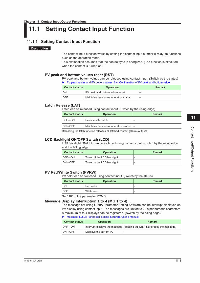
11-1IM 05P03D21-01EN
Contact Input/O
utput Functions
11
11.1 Setting Contact Input Function
11.1.1 Setting Contact Input FunctionDescription
The contact input function works by setting the contact input number (I relay) to functions such as the operation mode.This explanation assumes that the contact type is energized. (The function is executed when the contact is turned on)
PV peak and bottom values reset (RST)PVpeakandbottomvaluescanbereleasedusingcontactinput.(Switchbythestatus) PVpeakvaluesandPVbottomvalues:6.4ConfirmationofPVpeakandbottomvalue
Contact status Operation Remark
ON PVpeakandbottomvaluesreset –
OFF Maintains the current operation status –
Latch Release (LAT)Latch can be released using contact input. (Switch by the rising edge)
Contact status Operation Remark
OFF→ON Releases the latch –
ON→OFF Maintains the current operation status –
Releasing the latch function releases all latched contact (alarm) outputs.
LCD Backlight ON/OFF Switch (LCD)LCD backlight ON/OFF can be switched using contact input. (Switch by the rising edge and the falling edge)
Contact status Operation Remark
OFF→ON Turns off the LCD backlight –
ON→OFF Turns on the LCD backlight –
PV Red/White Switch (PVRW)PVcolorcanbeswitchedusingcontactinput.(Switchbythestatus)
Contact status Operation Remark
ON Red color –
OFF White color –
Set "10" to the parameter PCMD.
Message Display Interruption 1 to 4 (MG 1 to 4)The message set using LL50A Parameter Setting Software can be interrupt-displayed on PVdisplayusingcontactinput.Themessagesarelimitedto20alphanumericcharacters.A maximum of four displays can be registered. (Switch by the rising edge) Message:LL50AParameterSettingSoftwareUser’sManual
Contact status Operation Remark
OFF→ON Interrupt-displays the message Pressing the DISP key erases the message.
ON→OFF DisplaysthecurrentPV –
Chapter 11 Contact Input/Output Functions
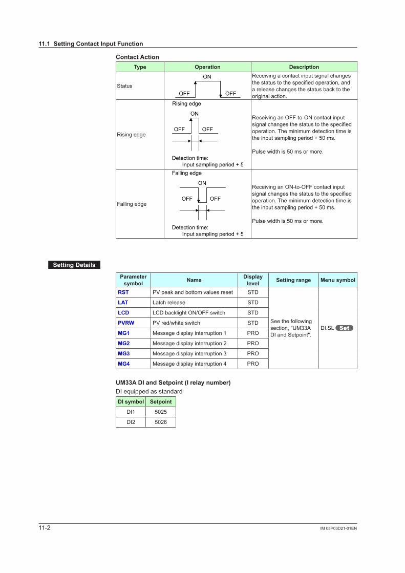
11-2 IM 05P03D21-01EN
Contact ActionType Operation Description
Status
ON
OFFOFF
Receiving a contact input signal changes thestatustothespecifiedoperation,anda release changes the status back to the original action.
Rising edge
Rising edge
ON
OFF OFF
Detection time: Input sampling period + 50 ms
Receiving an OFF-to-ON contact input signalchangesthestatustothespecifiedoperation. The minimum detection time is the input sampling period + 50 ms.
Pulse width is 50 ms or more.
Falling edge
Detection time: Input sampling period + 50 ms
Falling edge
ON
OFFOFF
Receiving an ON-to-OFF contact input signalchangesthestatustothespecifiedoperation. The minimum detection time is the input sampling period + 50 ms.
Pulse width is 50 ms or more.
Setting Details
Parameter symbol Name Display
level Setting range Menu symbol
RST PVpeakandbottomvaluesreset STD
See the following section, "UM33A DI and Setpoint".
DI.SL
LAT Latch release STD
LCD LCD backlight ON/OFF switch STD
PVRW PVred/whiteswitch STD
MG1 Message display interruption 1 PRO
MG2 Message display interruption 2 PRO
MG3 Message display interruption 3 PRO
MG4 Message display interruption 4 PRO
UM33A DI and Setpoint (I relay number)DI equipped as standardDI symbol Setpoint
DI1 5025
DI2 5026
11.1 Setting Contact Input Function
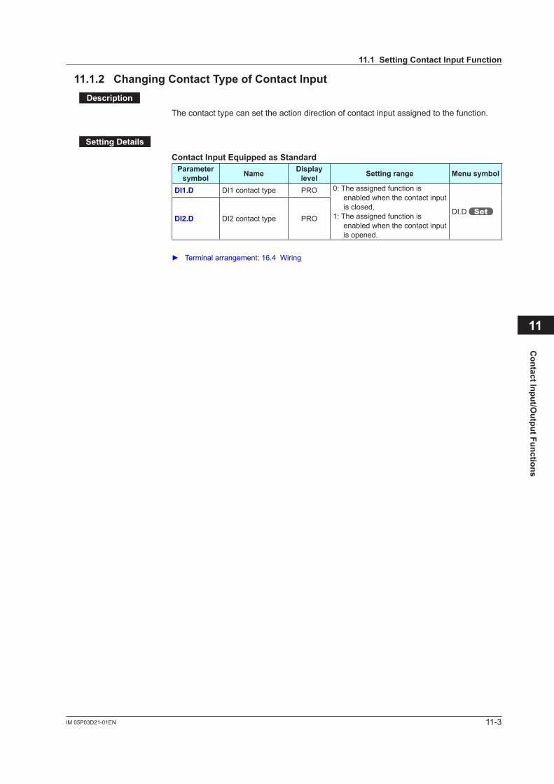
11-3IM 05P03D21-01EN
Contact Input/O
utput Functions
11
11.1.2 Changing Contact Type of Contact InputDescription
The contact type can set the action direction of contact input assigned to the function.
Setting Details
Contact Input Equipped as StandardParameter
symbol Name Display level Setting range Menu symbol
DI1.D DI1 contact type PRO 0: The assigned function is enabled when the contact input is closed.
1: The assigned function is enabled when the contact input is opened.
DI.D DI2.D DI2 contact type PRO
Terminalarrangement:16.4Wiring
11.1 Setting Contact Input Function
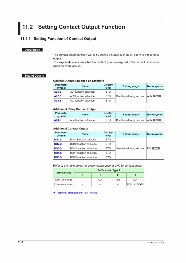
11-4 IM 05P03D21-01EN
11.2 Setting Contact Output Function
11.2.1 Setting Function of Contact Output
Description
The contact output function works by setting a status such as an alarm to the contact output.This explanation assumes that the contact type is energized. (The contact is turned on when an event occurs.)
Setting Details
Contact Output Equipped as StandardParameter
symbol Name Display level Setting range Menu symbol
AL1.S AL1 function selection STD
See the following section. ALM AL2.S AL2 function selection STD
AL3.S AL3 function selection STD
Additional Relay Contact OutputParameter
symbol Name Display level Setting range Menu symbol
AL4.S AL4 function selection STD See the following section. ALM
Additional Contact OutputParameter
symbol Name Display level Setting range Menu symbol
DO1.S DO11 function selection STD
See the following section. DO
DO2.S DO12 function selection STD
DO3.S DO13 function selection STD
DO4.S DO14 function selection STD
DO5.S DO15 function selection STD
Refer to the table below for presence/absence of UM33A contact output.
Terminal areaSuffixcode:Type2
0 1 2 3
ALM4 (101-103) – AL4 AL4 AL4
E1-terminal area – – – DO11 to DO15
Terminal arrangement: 16.4 Wiring
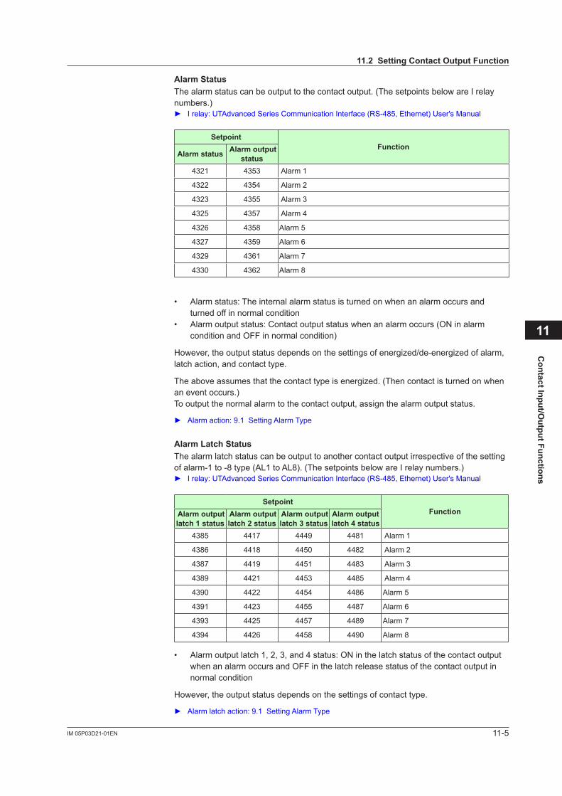
11-5IM 05P03D21-01EN
Contact Input/O
utput Functions
11
Alarm StatusThe alarm status can be output to the contact output. (The setpoints below are I relay numbers.) Irelay:UTAdvancedSeriesCommunicationInterface(RS-485,Ethernet)User'sManual
SetpointFunction
Alarm status Alarm output status
4321 4353 Alarm 1
4322 4354 Alarm 2
4323 4355 Alarm 3
4325 4357 Alarm 4
4326 4358 Alarm 5
4327 4359 Alarm 6
4329 4361 Alarm 7
4330 4362 Alarm 8
• Alarm status: The internal alarm status is turned on when an alarm occurs and turned off in normal condition
• Alarm output status: Contact output status when an alarm occurs (ON in alarm condition and OFF in normal condition)
However, the output status depends on the settings of energized/de-energized of alarm, latch action, and contact type.
The above assumes that the contact type is energized. (Then contact is turned on when an event occurs.)To output the normal alarm to the contact output, assign the alarm output status.
Alarm action: 9.1 Setting Alarm Type
Alarm Latch StatusThe alarm latch status can be output to another contact output irrespective of the setting of alarm-1 to -8 type (AL1 to AL8). (The setpoints below are I relay numbers.) I relay: UTAdvanced Series Communication Interface (RS-485, Ethernet) User's Manual
SetpointFunction Alarm output
latch 1 status Alarm output latch 2 status
Alarm output latch 3 status
Alarm output latch 4 status
4385 4417 4449 4481 Alarm 1
4386 4418 4450 4482 Alarm 2
4387 4419 4451 4483 Alarm 3
4389 4421 4453 4485 Alarm 4
4390 4422 4454 4486 Alarm 5
4391 4423 4455 4487 Alarm 6
4393 4425 4457 4489 Alarm 7
4394 4426 4458 4490 Alarm 8
• Alarm output latch 1, 2, 3, and 4 status: ON in the latch status of the contact output when an alarm occurs and OFF in the latch release status of the contact output in normal condition
However, the output status depends on the settings of contact type.
Alarm latch action: 9.1 Setting Alarm Type
11.2 Setting Contact Output Function
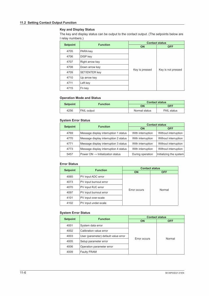
11-6 IM 05P03D21-01EN
Key and Display StatusThe key and display status can be output to the contact output. (The setpoints below are I relay numbers.)
Setpoint Function Contact statusON OFF
4705 PARA key
Key is pressed Key is not pressed
4706 DISP key
4707 Right arrow key
4708 Down arrow key
4709 SET/ENTER key
4710 Up arrow key
4711 Left key
4715 Fn key
Operation Mode and Status
Setpoint Function Contact statusON OFF
4256 FAIL output Normal status FAIL status
System Error Status
Setpoint Function Contact statusON OFF
4769 Message display interruption 1 status With interruption Without interruption
4770 Message display interruption 2 status With interruption Without interruption
4771 Message display interruption 3 status With interruption Without interruption
4773 Message display interruption 4 status With interruption Without interruption
5457 Power ON →Initializationstatus During operation Initializing the system
Error Status
Setpoint Function Contact statusON OFF
4065 PVinputADCerror
Error occurs Normal
4073 PVinputburnouterror
4070 PVinputRJC error
4097 PVinputburnouterror
4101 PVinputover-scale
4102 PVinputunder-scale
System Error Status
Setpoint Function Contact statusON OFF
4001 System data error
Error occurs Normal
4002 Calibration value error
4003 User (parameter) default value error
4005 Setup parameter error
4006 Operation parameter error
4009 Faulty FRAM
11.2 Setting Contact Output Function
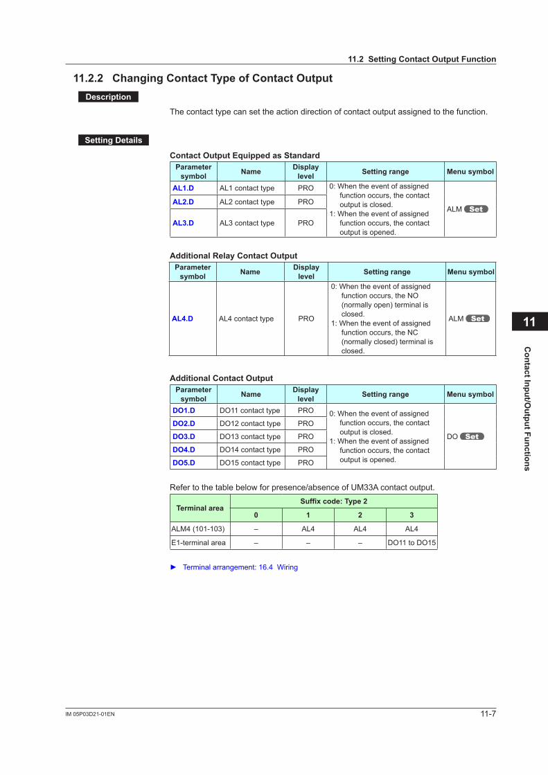
11-7IM 05P03D21-01EN
Contact Input/O
utput Functions
11
11.2.2 Changing Contact Type of Contact OutputDescription
The contact type can set the action direction of contact output assigned to the function.
Setting Details
Contact Output Equipped as StandardParameter
symbol Name Display level Setting range Menu symbol
AL1.D AL1 contact type PRO 0: When the event of assigned function occurs, the contact output is closed.
1: When the event of assigned function occurs, the contact output is opened.
ALM AL2.D AL2 contact type PRO
AL3.D AL3 contact type PRO
Additional Relay Contact OutputParameter
symbol Name Display level Setting range Menu symbol
AL4.D AL4 contact type PRO
0: When the event of assigned function occurs, the NO (normally open) terminal is closed.
1: When the event of assigned function occurs, the NC (normally closed) terminal is closed.
ALM
Additional Contact OutputParameter
symbol Name Display level Setting range Menu symbol
DO1.D DO11 contact type PRO 0: When the event of assigned function occurs, the contact output is closed.
1: When the event of assigned function occurs, the contact output is opened.
DO
DO2.D DO12 contact type PRO
DO3.D DO13 contact type PRO
DO4.D DO14 contact type PRO
DO5.D DO15 contact type PRO
Refer to the table below for presence/absence of UM33A contact output.
Terminal areaSuffixcode:Type2
0 1 2 3
ALM4 (101-103) – AL4 AL4 AL4
E1-terminal area – – – DO11 to DO15
Terminalarrangement:16.4Wiring
11.2 Setting Contact Output Function

Blank Page
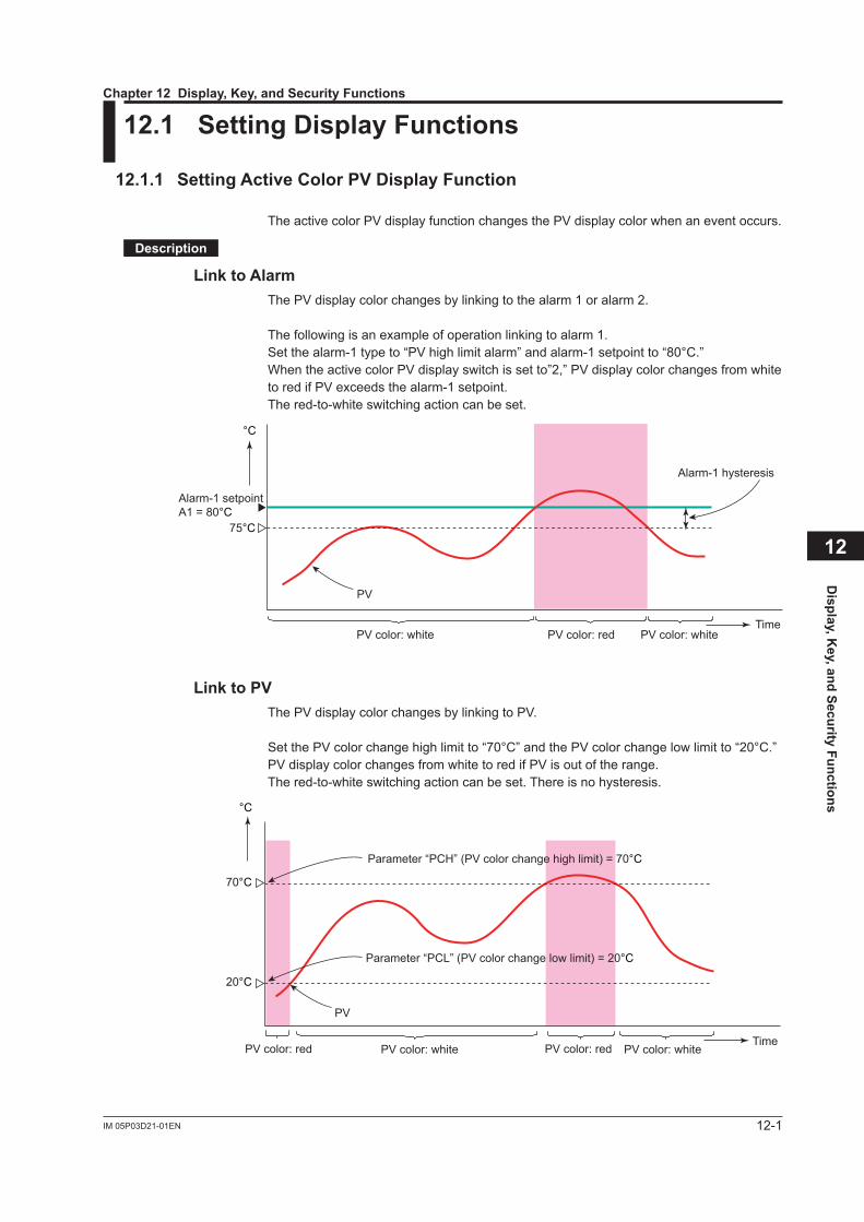
12-1IM 05P03D21-01EN
Display, K
ey, and Security Functions
12
12.1 Setting Display Functions
12.1.1 Setting Active Color PV Display Function
TheactivecolorPVdisplayfunctionchangesthePVdisplaycolorwhenaneventoccurs.
Description
Link to AlarmThePVdisplaycolorchangesbylinkingtothealarm1oralarm2.
The following is an example of operation linking to alarm 1.Setthealarm-1typeto“PVhighlimitalarm”andalarm-1setpointto“80°C.”WhentheactivecolorPVdisplayswitchissetto”2,”PVdisplaycolorchangesfromwhitetoredifPVexceedsthealarm-1setpoint.The red-to-white switching action can be set.
°C
TimePV color: redPV color: white PV color: white
Alarm-1 setpointA1 = 80°C
PV
75°C
Alarm-1 hysteresis
Link to PVThePVdisplaycolorchangesbylinkingtoPV.
SetthePVcolorchangehighlimitto“70°C”andthePVcolorchangelowlimitto“20°C.”PVdisplaycolorchangesfromwhitetoredifPVisoutoftherange.The red-to-white switching action can be set. There is no hysteresis.
Time
70°C
20°C
PV
Parameter “PCH” (PV color change high limit) = 70°C
Parameter “PCL” (PV color change low limit) = 20°C
°C
PV color: red PV color: redPV color: white PV color: white
Chapter 12 Display, Key, and Security Functions
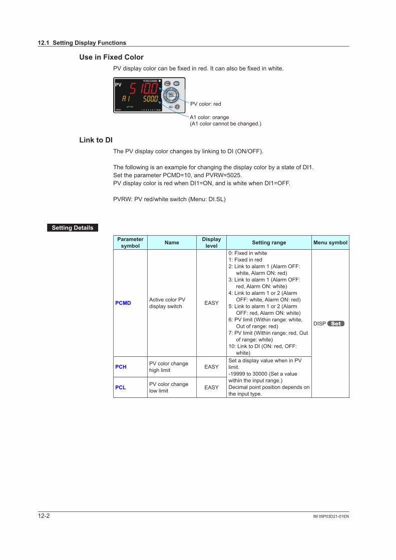
12-2 IM 05P03D21-01EN
Use in Fixed ColorPVdisplaycolorcanbefixedinred.Itcanalsobefixedinwhite.
PV color: red
A1 color: orange(A1 color cannot be changed.)
8
Link to DIThePVdisplaycolorchangesbylinkingtoDI(ON/OFF).
The following is an example for changing the display color by a state of DI1.SettheparameterPCMD=10,andPVRW=5025.PVdisplaycolorisredwhenDI1=ON,andiswhitewhenDI1=OFF.
PVRW:PVred/whiteswitch(Menu:DI.SL)
Setting Details
Parameter symbol Name Display
level Setting range Menu symbol
PCMD ActivecolorPVdisplay switch EASY
0: Fixed in white1: Fixed in red2: Link to alarm 1 (Alarm OFF:
white, Alarm ON: red)3: Link to alarm 1 (Alarm OFF:
red, Alarm ON: white)4: Link to alarm 1 or 2 (Alarm
OFF: white, Alarm ON: red)5: Link to alarm 1 or 2 (Alarm
OFF: red, Alarm ON: white)6:PVlimit(Withinrange:white,
Out of range: red)7:PVlimit(Withinrange:red,Out
of range: white)10: Link to DI (ON: red, OFF:
white)
DISP
PCH PVcolorchangehigh limit EASY
SetadisplayvaluewheninPVlimit.-19999 to 30000 (Set a value within the input range.)Decimal point position depends on the input type.
PCL PVcolorchangelow limit EASY
12.1 Setting Display Functions
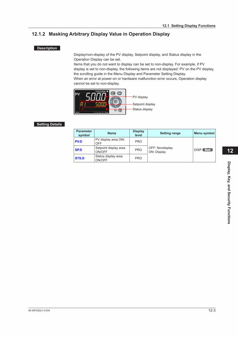
12-3IM 05P03D21-01EN
Display, K
ey, and Security Functions
12
12.1.2 Masking Arbitrary Display Value in Operation Display
Description
Display/non-displayofthePVdisplay,Setpointdisplay,andStatusdisplayintheOperation Display can be set.Itemsthatyoudonotwanttodisplaycanbesettonon-display.Forexample,ifPVdisplayissettonon-display,thefollowingitemsarenotdisplayed:PVonthePVdisplay,the scrolling guide in the Menu Display and Parameter Setting Display.When an error at power-on or hardware malfunction error occurs, Operation display cannot be set to non-display.
PV display
Setpoint displayStatus display
8
Setting Details
Parameter symbol Name Display
level Setting range Menu symbol
PV.D PVdisplayareaON/OFF PRO
OFF: NondisplayON: Display DISP SP.D Setpoint display area
ON/OFF PRO
STS.D Status display area ON/OFF PRO
12.1 Setting Display Functions
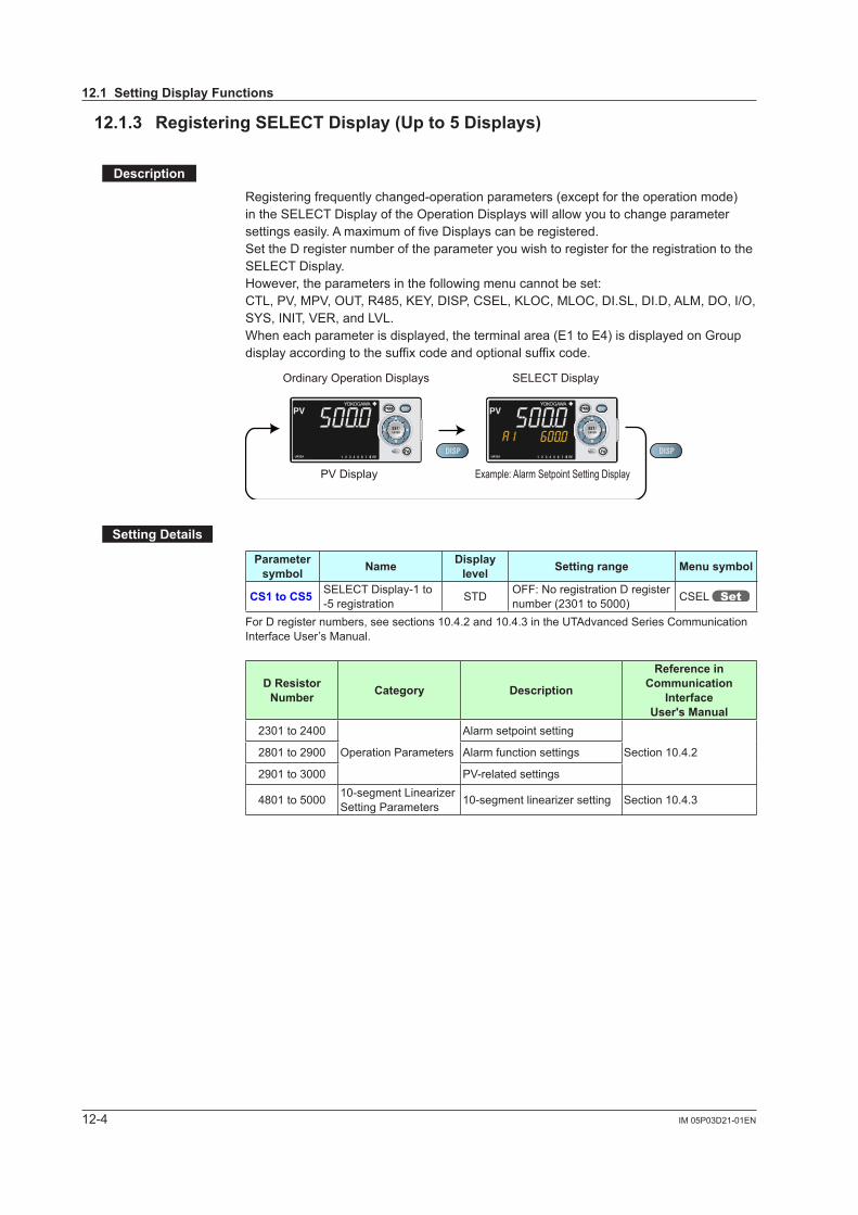
12-4 IM 05P03D21-01EN
12.1.3 Registering SELECT Display (Up to 5 Displays)
Description
Registering frequently changed-operation parameters (except for the operation mode) in the SELECT Display of the Operation Displays will allow you to change parameter settings easily. A maximum of five Displays can be registered.Set the D register number of the parameter you wish to register for the registration to the SELECT Display.However, the parameters in the following menu cannot be set:CTL,PV,MPV,OUT,R485,KEY,DISP,CSEL,KLOC,MLOC,DI.SL,DI.D,ALM,DO,I/O,SYS,INIT,VER,andLVL.When each parameter is displayed, the terminal area (E1 to E4) is displayed on Group display according to the suffix code and optional suffix code.
PV Display
Ordinary Operation Displays SELECT Display
Example: Alarm Setpoint Setting Display
8 8
Setting Details
Parameter symbol Name Display
level Setting range Menu symbol
CS1 to CS5 SELECT Display-1 to -5 registration STD OFF: No registration D register
number (2301 to 5000) CSEL
For D register numbers, see sections 10.4.2 and 10.4.3 in the UTAdvanced Series Communication Interface User’s Manual.
D Resistor Number Category Description
Reference in Communication
Interface User's Manual
2301 to 2400
Operation Parameters
Alarm setpoint setting
Section 10.4.22801 to 2900 Alarm function settings
2901 to 3000 PV-relatedsettings
4801 to 5000 10-segment Linearizer Setting Parameters 10-segment linearizer setting Section 10.4.3
12.1 Setting Display Functions
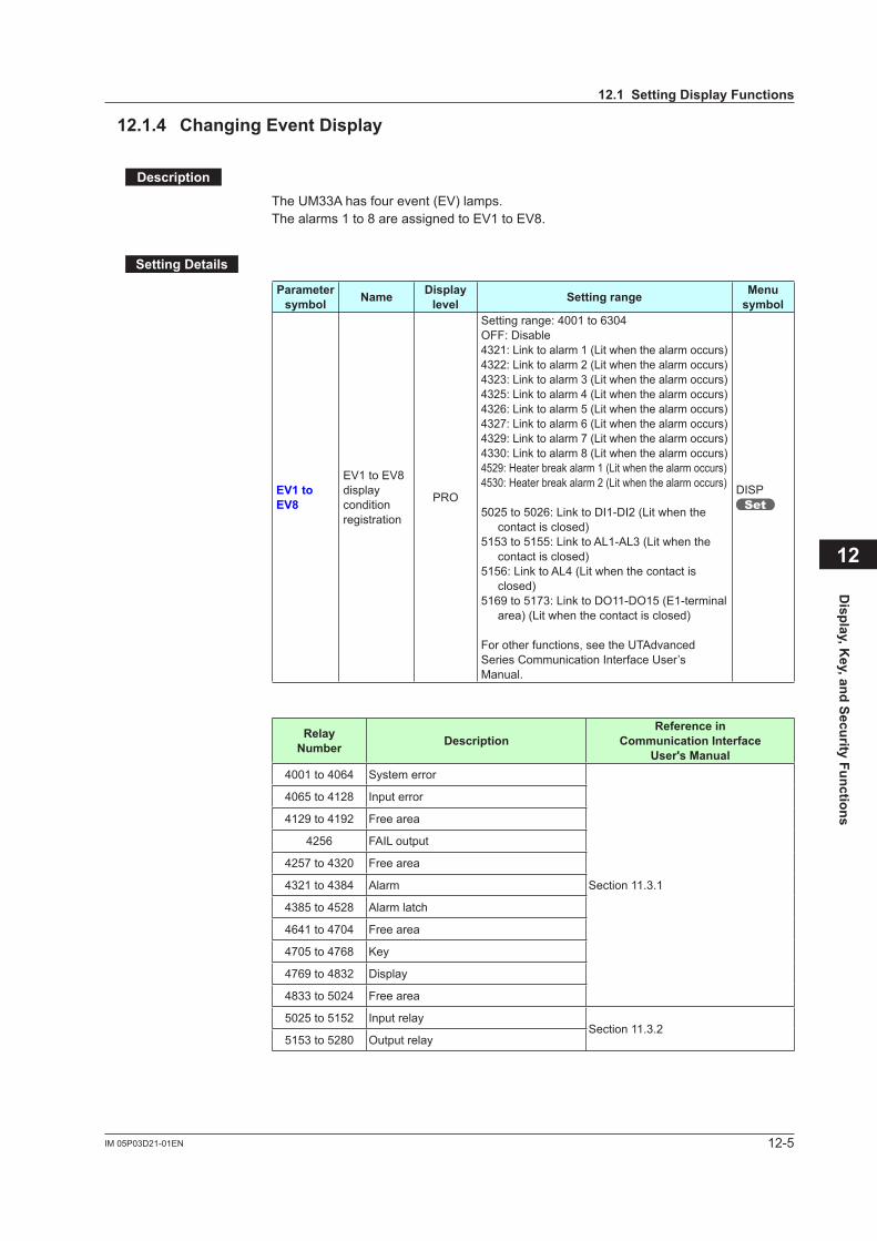
12-5IM 05P03D21-01EN
Display, K
ey, and Security Functions
12
12.1.4 Changing Event Display
Description
TheUM33Ahasfourevent(EV)lamps.Thealarms1to8areassignedtoEV1toEV8.
Setting Details
Parameter symbol Name Display
level Setting range Menu symbol
EV1 to EV8
EV1toEV8display condition registration
PRO
Setting range: 4001 to 6304OFF: Disable4321: Link to alarm 1 (Lit when the alarm occurs)4322: Link to alarm 2 (Lit when the alarm occurs)4323: Link to alarm 3 (Lit when the alarm occurs)4325: Link to alarm 4 (Lit when the alarm occurs)4326: Link to alarm 5 (Lit when the alarm occurs)4327: Link to alarm 6 (Lit when the alarm occurs)4329: Link to alarm 7 (Lit when the alarm occurs)4330: Link to alarm 8 (Lit when the alarm occurs)4529: Heater break alarm 1 (Lit when the alarm occurs)4530: Heater break alarm 2 (Lit when the alarm occurs)
5025 to 5026: Link to DI1-DI2 (Lit when the contact is closed)
5153 to 5155: Link to AL1-AL3 (Lit when the contact is closed)
5156: Link to AL4 (Lit when the contact is closed)
5169 to 5173: Link to DO11-DO15 (E1-terminal area) (Lit when the contact is closed)
For other functions, see the UTAdvanced Series Communication Interface User’s Manual.
DISP
Relay Number Description
Reference in Communication Interface
User's Manual4001 to 4064 System error
Section 11.3.1
4065 to 4128 Input error
4129 to 4192 Free area
4256 FAIL output
4257 to 4320 Free area
4321 to 4384 Alarm
4385 to 4528 Alarm latch
4641 to 4704 Free area
4705 to 4768 Key
4769 to 4832 Display
4833 to 5024 Free area
5025 to 5152 Input relaySection 11.3.2
5153 to 5280 Output relay
12.1 Setting Display Functions
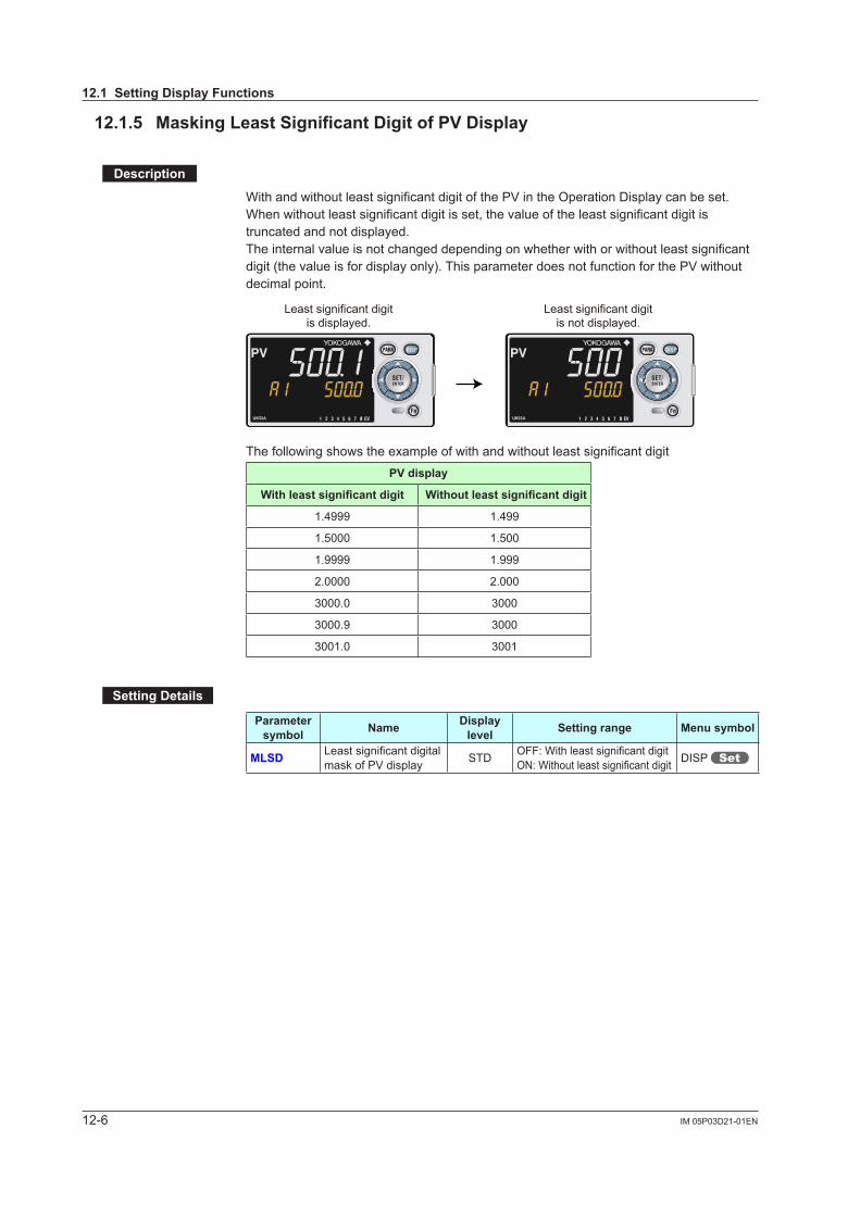
12-6 IM 05P03D21-01EN
12.1.5 Masking Least Significant Digit of PV Display
Description
WithandwithoutleastsignificantdigitofthePVintheOperationDisplaycanbeset.When without least significant digit is set, the value of the least significant digit is truncated and not displayed.The internal value is not changed depending on whether with or without least significant digit(thevalueisfordisplayonly).ThisparameterdoesnotfunctionforthePVwithoutdecimal point.
Least significant digitis displayed.
Least significant digitis not displayed.
8 8
The following shows the example of with and without least significant digitPV display
Withleastsignificantdigit Withoutleastsignificantdigit
1.4999 1.499
1.5000 1.500
1.9999 1.999
2.0000 2.000
3000.0 3000
3000.9 3000
3001.0 3001
Setting Details
Parameter symbol Name Display
level Setting range Menu symbol
MLSD LeastsignificantdigitalmaskofPVdisplay STD OFF:Withleastsignificantdigit
ON:Withoutleastsignificantdigit DISP
12.1 Setting Display Functions
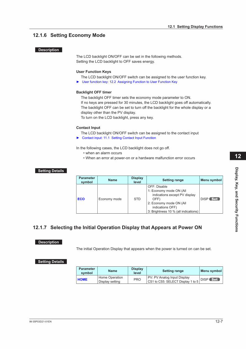
12-7IM 05P03D21-01EN
12.1.6 Setting Economy Mode
Description
The LCD backlight ON/OFF can be set in the following methods.Setting the LCD backlight to OFF saves energy.
User Function Keys The LCD backlight ON/OFF switch can be assigned to the user function key. Userfunctionkey:12.2AssigningFunctiontoUserFunctionKey
Backlight OFF timer The backlight OFF timer sets the economy mode parameter to ON.
If no keys are pressed for 30 minutes, the LCD backlight goes off automatically. The backlight OFF can be set to turn off the backlight for the whole display or a displayotherthanthePVdisplay. To turn on the LCD backlight, press any key.
Contact Input The LCD backlight ON/OFF switch can be assigned to the contact input Contactinput:11.1SettingContactInputFunction
In the following cases, the LCD backlight does not go off. • when an alarm occurs • When an error at power-on or a hardware malfunction error occurs
Setting Details
Parameter symbol Name Display
level Setting range Menu symbol
ECO Economy mode STD
OFF: Disable1: Economy mode ON (All
indicationsexceptPVdisplayOFF)
2: Economy mode ON (All indications OFF)
3:Brightness10%(allindications)
DISP
12.1.7 Selecting the Initial Operation Display that Appears at Power ON
Description
The initial Operation Display that appears when the power is turned on can be set.
Setting Details
Parameter symbol Name Display
level Setting range Menu symbol
HOME Home Operation Display setting PRO PV:PVAnalogInputDisplay
CS1 to CS5: SELECT Display 1 to 5 DISP
Display, K
ey, and Security Functions
12
12.1 Setting Display Functions
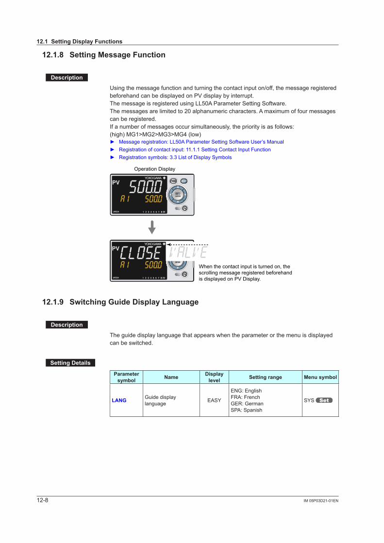
12-8 IM 05P03D21-01EN
12.1.8 Setting Message Function
Description
Using the message function and turning the contact input on/off, the message registered beforehandcanbedisplayedonPVdisplaybyinterrupt.The message is registered using LL50A Parameter Setting Software.The messages are limited to 20 alphanumeric characters. A maximum of four messages can be registered.If a number of messages occur simultaneously, the priority is as follows:(high) MG1>MG2>MG3>MG4 (low) Messageregistration:LL50AParameterSettingSoftwareUser’sManual Registration of contact input: 11.1.1 Setting Contact Input Function Registration symbols: 3.3 List of Display Symbols
When the contact input is turned on, the scrolling message registered beforehand is displayed on PV Display.
Operation Display
8
8
12.1.9 Switching Guide Display Language
Description
The guide display language that appears when the parameter or the menu is displayed can be switched.
Setting Details
Parameter symbol Name Display
level Setting range Menu symbol
LANG Guide display language EASY
ENG: EnglishFRA: FrenchGER: GermanSPA: Spanish
SYS
12.1 Setting Display Functions
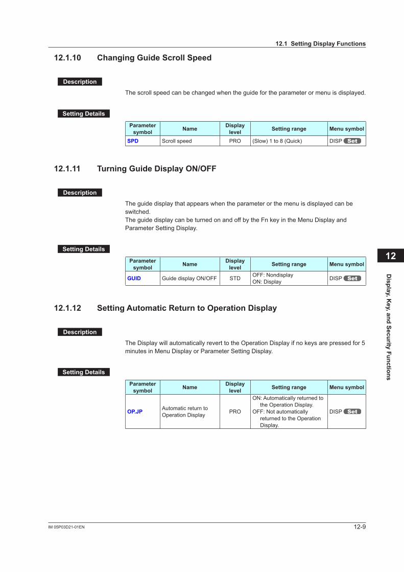
12-9IM 05P03D21-01EN
12.1.10 Changing Guide Scroll Speed
Description
The scroll speed can be changed when the guide for the parameter or menu is displayed.
Setting Details
Parameter symbol Name Display
level Setting range Menu symbol
SPD Scroll speed PRO (Slow) 1 to 8 (Quick) DISP
12.1.11 Turning Guide Display ON/OFF
Description
The guide display that appears when the parameter or the menu is displayed can be switched.The guide display can be turned on and off by the Fn key in the Menu Display and Parameter Setting Display.
Setting Details
Parameter symbol Name Display
level Setting range Menu symbol
GUID Guide display ON/OFF STD OFF: NondisplayON: Display DISP
12.1.12 Setting Automatic Return to Operation Display
Description
The Display will automatically revert to the Operation Display if no keys are pressed for 5 minutes in Menu Display or Parameter Setting Display.
Setting Details
Parameter symbol Name Display
level Setting range Menu symbol
OP.JP Automatic return to Operation Display PRO
ON: Automatically returned to the Operation Display.
OFF: Not automatically returned to the Operation Display.
DISP
Display, K
ey, and Security Functions
12
12.1 Setting Display Functions
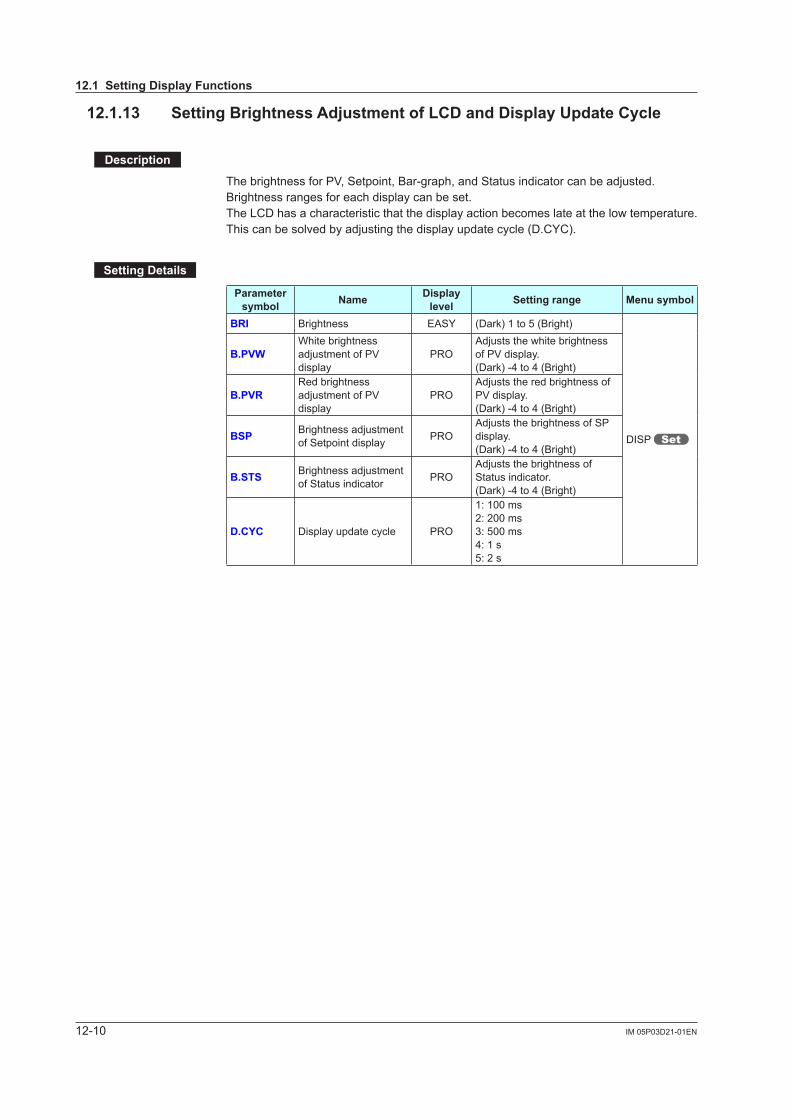
12-10 IM 05P03D21-01EN
12.1.13 Setting Brightness Adjustment of LCD and Display Update Cycle
Description
ThebrightnessforPV,Setpoint,Bar-graph,andStatusindicatorcanbeadjusted.Brightness ranges for each display can be set.The LCD has a characteristic that the display action becomes late at the low temperature.Thiscanbesolvedbyadjustingthedisplayupdatecycle(D.CYC).
Setting Details
Parameter symbol Name Display
level Setting range Menu symbol
BRI Brightness EASY (Dark) 1 to 5 (Bright)
DISP
B.PVWWhite brightness adjustmentofPVdisplay
PROAdjuststhewhitebrightnessofPVdisplay.(Dark) -4 to 4 (Bright)
B.PVRRed brightness adjustmentofPVdisplay
PROAdjuststheredbrightnessofPVdisplay.(Dark) -4 to 4 (Bright)
BSP Brightnessadjustmentof Setpoint display PRO
AdjuststhebrightnessofSPdisplay.(Dark) -4 to 4 (Bright)
B.STS Brightnessadjustmentof Status indicator PRO
AdjuststhebrightnessofStatus indicator.(Dark) -4 to 4 (Bright)
D.CYC Display update cycle PRO
1: 100 ms2: 200 ms3: 500 ms4: 1 s5: 2 s
12.1 Setting Display Functions
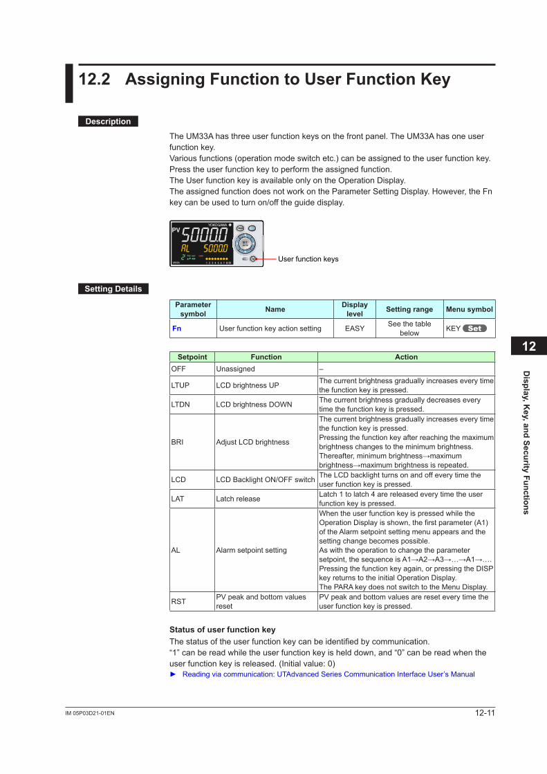
12-11IM 05P03D21-01EN
12.2 Assigning Function to User Function Key
Description
The UM33A has three user function keys on the front panel. The UM33A has one user function key.Variousfunctions(operationmodeswitchetc.)canbeassignedtotheuserfunctionkey.Press the user function key to perform the assigned function.The User function key is available only on the Operation Display.The assigned function does not work on the Parameter Setting Display. However, the Fn key can be used to turn on/off the guide display.
User function keys8
Setting Details
Parameter symbol Name Display
level Setting range Menu symbol
Fn User function key action setting EASY See the table below KEY
Setpoint Function ActionOFF Unassigned –
LTUP LCD brightness UP The current brightness gradually increases every time the function key is pressed.
LTDN LCD brightness DOWN The current brightness gradually decreases every time the function key is pressed.
BRI AdjustLCDbrightness
The current brightness gradually increases every time the function key is pressed.Pressing the function key after reaching the maximum brightness changes to the minimum brightness.Thereafter,minimumbrightness→maximumbrightness→maximumbrightnessisrepeated.
LCD LCD Backlight ON/OFF switch The LCD backlight turns on and off every time the user function key is pressed.
LAT Latch release Latch 1 to latch 4 are released every time the user function key is pressed.
AL Alarm setpoint setting
When the user function key is pressed while the OperationDisplayisshown,thefirstparameter(A1)of the Alarm setpoint setting menu appears and the setting change becomes possible.As with the operation to change the parameter setpoint,thesequenceisA1→A2→A3→…→A1→….Pressing the function key again, or pressing the DISP key returns to the initial Operation Display.The PARA key does not switch to the Menu Display.
RST PVpeakandbottomvaluesreset
PVpeakandbottomvaluesarereseteverytimetheuser function key is pressed.
Status of user function keyThe status of the user function key can be identified by communication.“1” can be read while the user function key is held down, and “0” can be read when the user function key is released. (Initial value: 0) Readingviacommunication:UTAdvancedSeriesCommunicationInterfaceUser’sManual
Display, K
ey, and Security Functions
12
12-12 IM 05P03D21-01EN
Fn key operation in the Parameter Setting DisplayIntheMenuDisplayandParameterSettingDisplay,theguideisdisplayedonPVdisplay.Atthistime,usetheFnkeytoturnonandofftheguidedisplayonPVdisplay.Ameasuredinputvalue(PV)isdisplayedintheONstate.
12.2 Assigning Function to User Function Key

12-13IM 05P03D21-01EN
12.3 Setting Security Functions
12.3.1 Setting a Password
Description
The password function can prevent inadvertent changes to the parameter settings.If a password is set, the checking is required when moving to the Setup Parameter Setting Display. When the password is verified, can be changed to the Setup Parameter Setting Display. The parameters in the following menus can be set only when the password is verified.CTL,PV,MPV,OUT,R485,KEY,DISP,CSEL,KLOC,MLOC,DI.SL,DI.D,ALM,DO,I/O,SYS,INIT,VER,andLVL.
Always remember your password when using the password function.
Setting Details
Parameter symbol Name Display
level Setting range Menu symbol
PASS Password setting EASY 0 (No password) to 65535 SYS
12.3.2 Setting Parameter Display Level
Description
Parameter display level can be set according to the setting level. Parameterdisplaylevel:Chapter17Parameters
Setting Details
Parameter symbol Name Display
level Setting range Menu symbol
LEVL Parameter display level EASY
EASY: Easy setting modeSTD: Standard setting modePRO: Professional setting mode
LVL
Display, K
ey, and Security Functions
12
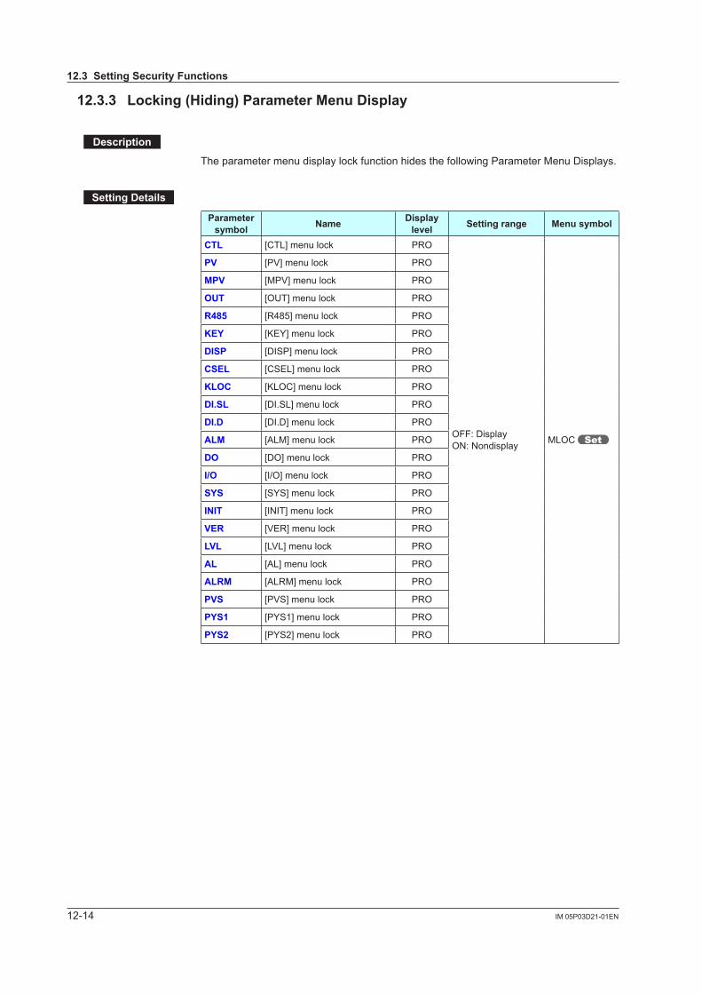
12-14 IM 05P03D21-01EN
12.3.3 Locking (Hiding) Parameter Menu Display
Description
The parameter menu display lock function hides the following Parameter Menu Displays.
Setting Details
Parameter symbol Name Display
level Setting range Menu symbol
CTL [CTL] menu lock PRO
OFF: DisplayON: Nondisplay MLOC
PV [PV]menulock PRO
MPV [MPV]menulock PRO
OUT [OUT] menu lock PRO
R485 [R485] menu lock PRO
KEY [KEY] menu lock PRO
DISP [DISP] menu lock PRO
CSEL [CSEL] menu lock PRO
KLOC [KLOC] menu lock PRO
DI.SL [DI.SL] menu lock PRO
DI.D [DI.D] menu lock PRO
ALM [ALM] menu lock PRO
DO [DO] menu lock PRO
I/O [I/O] menu lock PRO
SYS [SYS] menu lock PRO
INIT [INIT] menu lock PRO
VER [VER]menulock PRO
LVL [LVL]menulock PRO
AL [AL] menu lock PRO
ALRM [ALRM] menu lock PRO
PVS [PVS]menulock PRO
PYS1 [PYS1] menu lock PRO
PYS2 [PYS2] menu lock PRO
12.3 Setting Security Functions
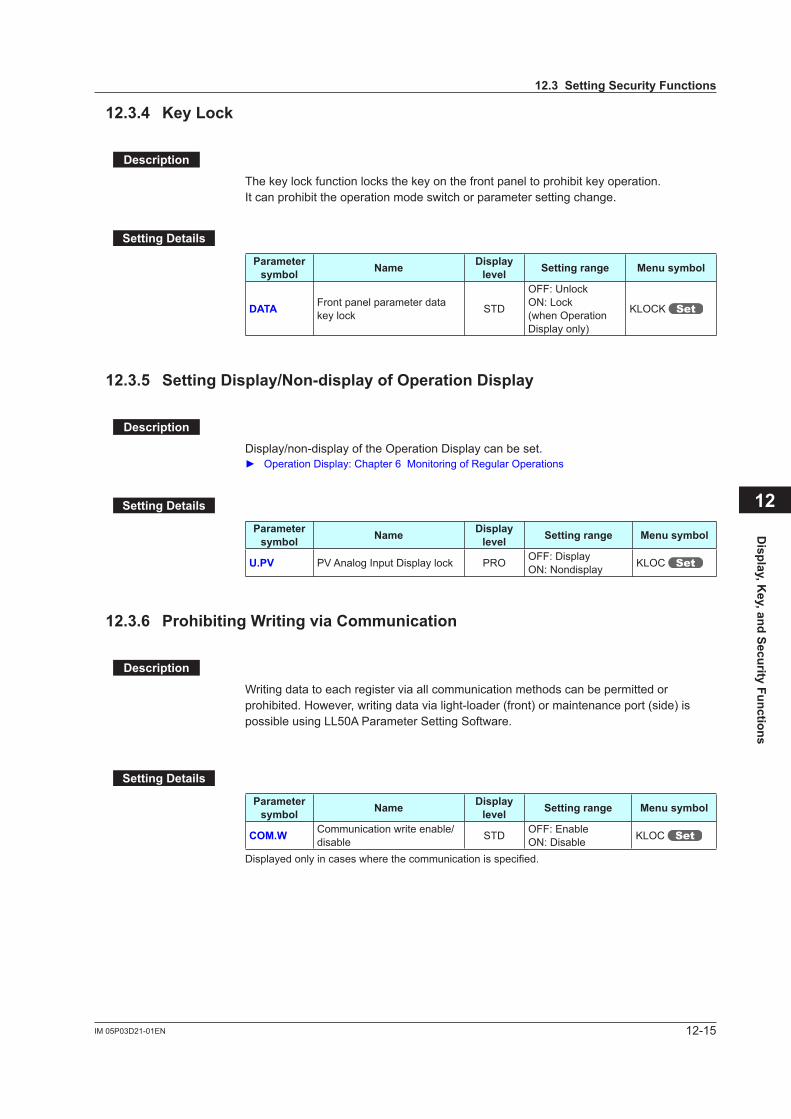
12-15IM 05P03D21-01EN
12.3.4 Key Lock
Description
The key lock function locks the key on the front panel to prohibit key operation.It can prohibit the operation mode switch or parameter setting change.
Setting Details
Parameter symbol Name Display
level Setting range Menu symbol
DATA Front panel parameter data key lock STD
OFF: UnlockON: Lock(when Operation Display only)
KLOCK
12.3.5 Setting Display/Non-display of Operation Display
Description
Display/non-display of the Operation Display can be set. Operation Display: Chapter 6 Monitoring of Regular Operations
Setting Details
Parameter symbol Name Display
level Setting range Menu symbol
U.PV PVAnalogInputDisplaylock PRO OFF: DisplayON: Nondisplay KLOC
12.3.6 Prohibiting Writing via Communication
Description
Writing data to each register via all communication methods can be permitted or prohibited. However, writing data via light-loader (front) or maintenance port (side) is possible using LL50A Parameter Setting Software.
Setting Details
Parameter symbol Name Display
level Setting range Menu symbol
COM.W Communication write enable/disable STD OFF: Enable
ON: Disable KLOC
Displayed only in cases where the communication is specified.
Display, K
ey, and Security Functions
12
12.3 Setting Security Functions
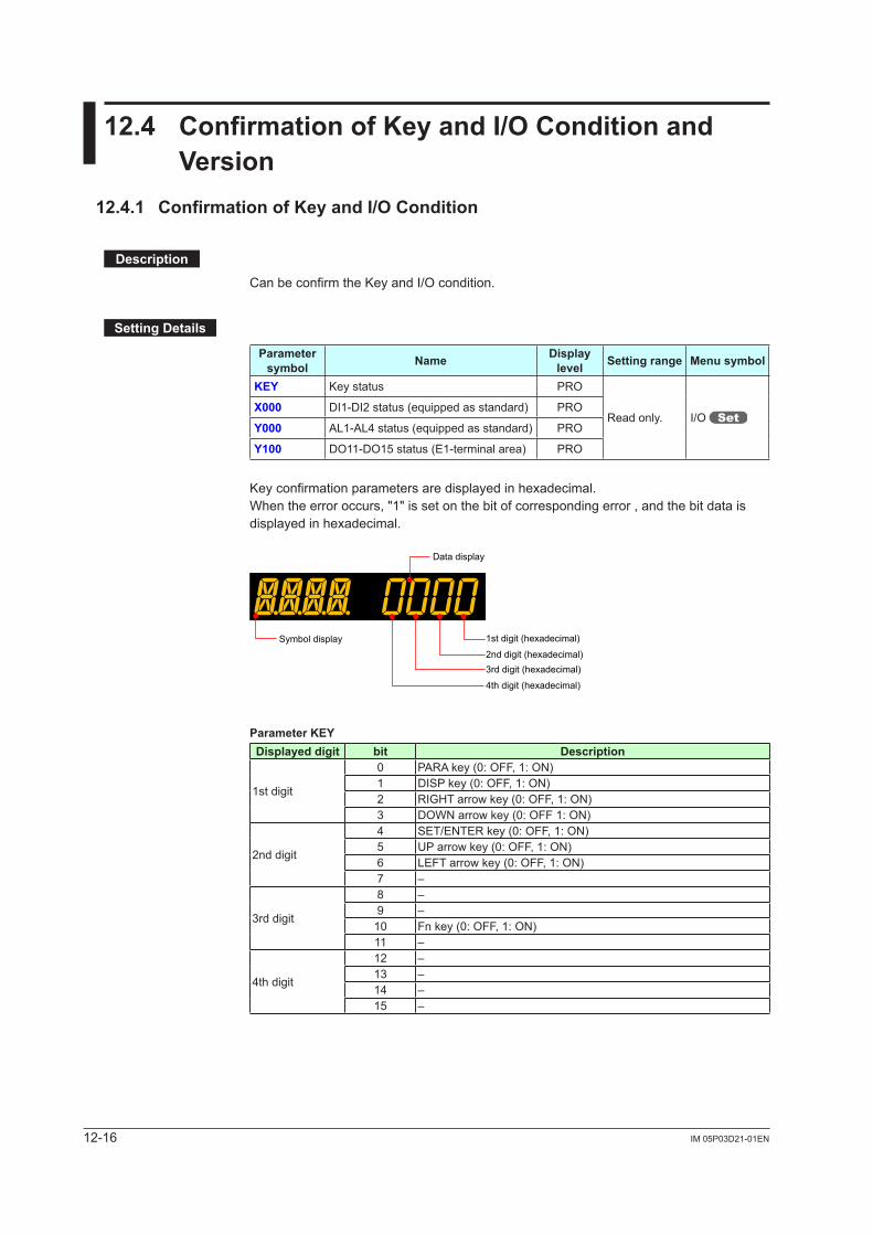
12-16 IM 05P03D21-01EN
12.4 Confirmation of Key and I/O Condition and Version
12.4.1 Confirmation of Key and I/O Condition
Description
Can be confirm the Key and I/O condition.
Setting Details
Parameter symbol Name Display
level Setting range Menu symbol
KEY Key status PRO
Read only. I/O X000 DI1-DI2 status (equipped as standard) PRO
Y000 AL1-AL4 status (equipped as standard) PRO
Y100 DO11-DO15 status (E1-terminal area) PRO
Key confirmation parameters are displayed in hexadecimal.When the error occurs, "1" is set on the bit of corresponding error , and the bit data is displayed in hexadecimal.
Data display
1st digit (hexadecimal)
2nd digit (hexadecimal)3rd digit (hexadecimal)
4th digit (hexadecimal)
Symbol display
Parameter KEYDisplayed digit bit Description
1st digit
0 PARA key (0: OFF, 1: ON)1 DISP key (0: OFF, 1: ON)2 RIGHT arrow key (0: OFF, 1: ON)3 DOWN arrow key (0: OFF 1: ON)
2nd digit
4 SET/ENTER key (0: OFF, 1: ON)5 UP arrow key (0: OFF, 1: ON)6 LEFT arrow key (0: OFF, 1: ON)7 –
3rd digit
8 –9 –10 Fn key (0: OFF, 1: ON)11 –
4th digit
12 –13 –14 –15 –
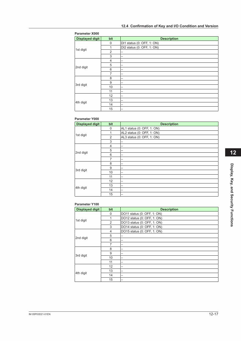
12-17IM 05P03D21-01EN
Parameter X000Displayed digit bit Description
1st digit
0 DI1 status (0: OFF, 1: ON)1 DI2 status (0: OFF, 1: ON)2 –3 –
2nd digit
4 –5 –6 –7 –
3rd digit
8 –9 –10 –11 –
4th digit
12 –13 –14 –15 –
Parameter Y000Displayed digit bit Description
1st digit
0 AL1 status (0: OFF, 1: ON)1 AL2 status (0: OFF, 1: ON)2 AL3 status (0: OFF, 1: ON)3 –
2nd digit
4 –5 –6 –7 –
3rd digit
8 –9 –10 –11 –
4th digit
12 –13 –14 –15 –
Parameter Y100Displayed digit bit Description
1st digit
0 DO11 status (0: OFF, 1: ON)1 DO12 status (0: OFF, 1: ON)2 DO13 status (0: OFF, 1: ON)3 DO14 status (0: OFF, 1: ON)
2nd digit
4 DO15 status (0: OFF, 1: ON)5 –6 –7 –
3rd digit
8 –9 –10 –11 –
4th digit
12 –13 –14 –15 –
Display, K
ey, and Security Functions
12
12.4 Confirmation of Key and I/O Condition and Version
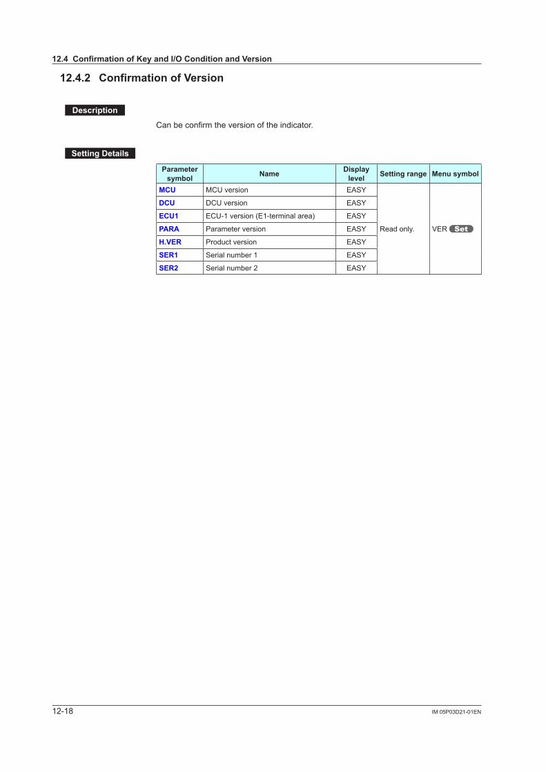
12-18 IM 05P03D21-01EN
12.4.2 Confirmation of Version
Description
Can be confirm the version of the indicator.
Setting Details
Parameter symbol Name Display
level Setting range Menu symbol
MCU MCU version EASY
Read only. VER
DCU DCU version EASY
ECU1 ECU-1 version (E1-terminal area) EASY
PARA Parameter version EASY
H.VER Product version EASY
SER1 Serial number 1 EASY
SER2 Serial number 2 EASY
12.4 Confirmation of Key and I/O Condition and Version
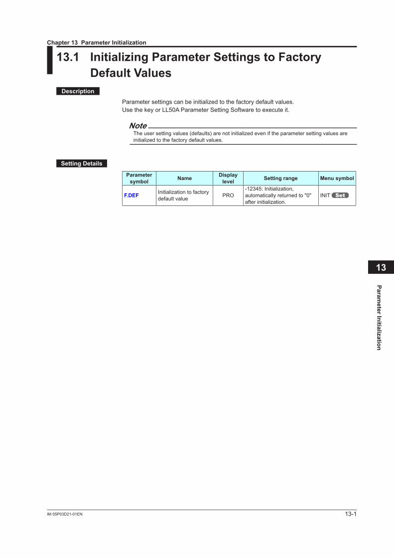
13-1IM 05P03D21-01EN
Parameter Initialization
13
13.1 Initializing Parameter Settings to Factory Default Values
Description
Parameter settings can be initialized to the factory default values.Use the key or LL50A Parameter Setting Software to execute it.
NoteThe user setting values (defaults) are not initialized even if the parameter setting values are initialized to the factory default values.
Setting Details
Parameter symbol Name Display
level Setting range Menu symbol
F.DEF Initialization to factory default value PRO
-12345: Initialization, automatically returned to "0" after initialization.
INIT
Chapter 13 Parameter Initialization
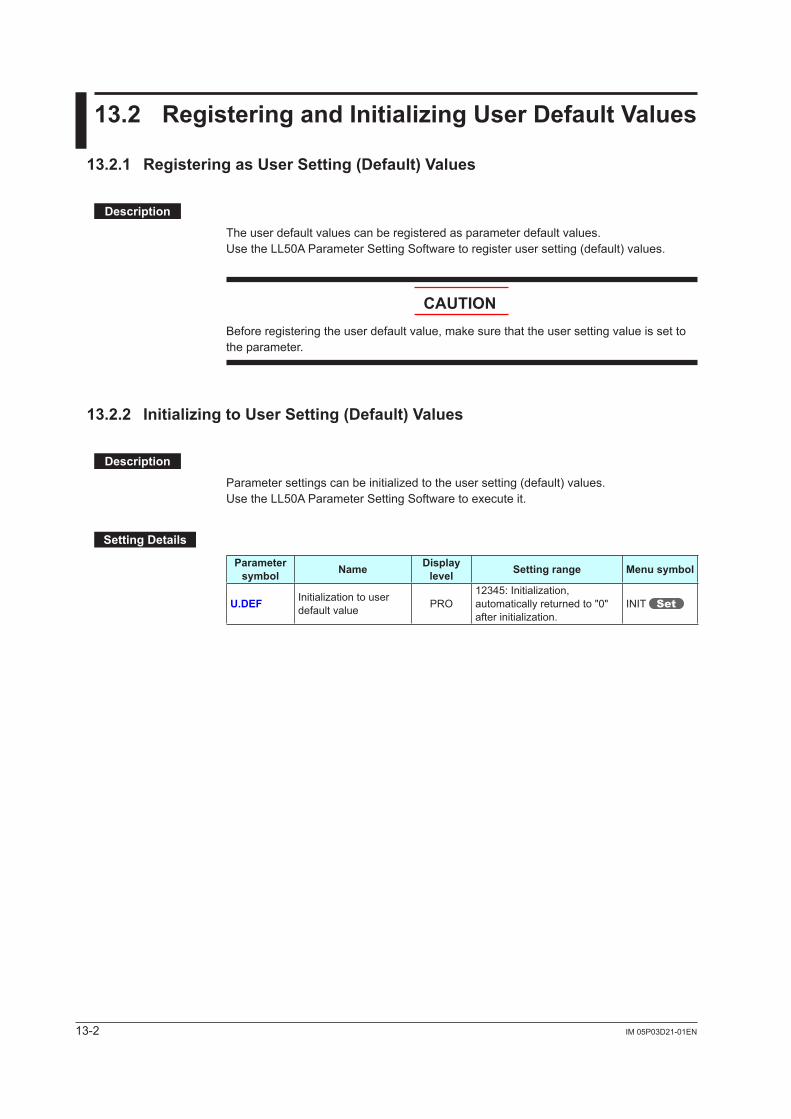
13-2 IM 05P03D21-01EN
13.2 Registering and Initializing User Default Values
13.2.1 Registering as User Setting (Default) Values
Description
The user default values can be registered as parameter default values.Use the LL50A Parameter Setting Software to register user setting (default) values.
CAUTIONBefore registering the user default value, make sure that the user setting value is set to the parameter.
13.2.2 Initializing to User Setting (Default) Values
Description
Parameter settings can be initialized to the user setting (default) values.Use the LL50A Parameter Setting Software to execute it.
Setting Details
Parameter symbol Name Display
level Setting range Menu symbol
U.DEF Initialization to user default value PRO
12345: Initialization, automatically returned to "0" after initialization.
INIT
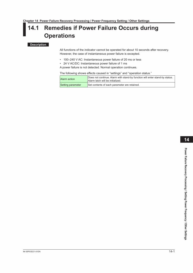
14-1IM 05P03D21-01EN
Power Failure Recovery Processing / Setting Power Frequency / Other Settings
14
14.1 Remedies if Power Failure Occurs during Operations
Description
All functions of the indicator cannot be operated for about 10 seconds after recovery.However, the case of instantaneous power failure is excepted.
• 100–240VAC:Instantaneouspowerfailureof20msorless• 24VAC/DC:Instantaneouspowerfailureof1msA power failure is not detected. Normal operation continues.
The following shows effects caused in “settings” and “operation status.”
Alarm action Does not continue. Alarm with stand-by function will enter stand-by status.Alarm latch will be initialized.
Setting parameter Set contents of each parameter are retained.
Chapter 14 Power Failure Recovery Processing / Power Frequency Setting / Other Settings
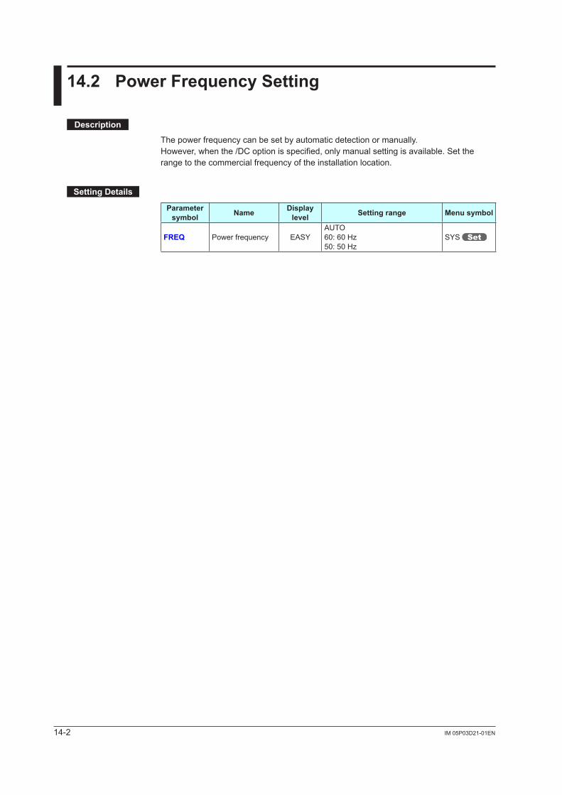
14-2 IM 05P03D21-01EN
14.2 Power Frequency Setting
Description
The power frequency can be set by automatic detection or manually.However, when the /DC option is specified, only manual setting is available. Set the range to the commercial frequency of the installation location.
Setting Details
Parameter symbol Name Display
level Setting range Menu symbol
FREQ Power frequency EASYAUTO60: 60 Hz50: 50 Hz
SYS
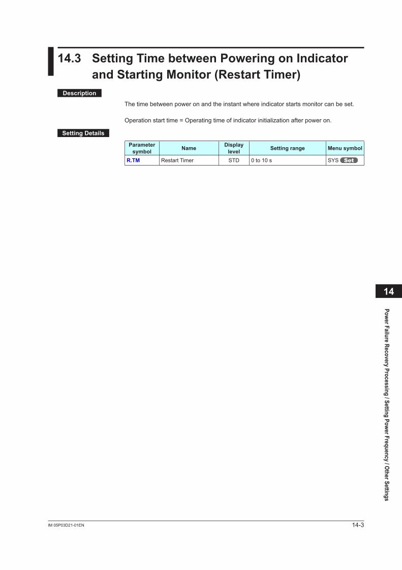
14-3IM 05P03D21-01EN
14.3 Setting Time between Powering on Indicator and Starting Monitor (Restart Timer)
Description
The time between power on and the instant where indicator starts monitor can be set.
Operation start time = Operating time of indicator initialization after power on.
Setting Details
Parameter symbol Name Display
level Setting range Menu symbol
R.TM Restart Timer STD 0 to 10 s SYS
Power Failure Recovery Processing / Setting Power Frequency / Other Settings
14

Blank Page
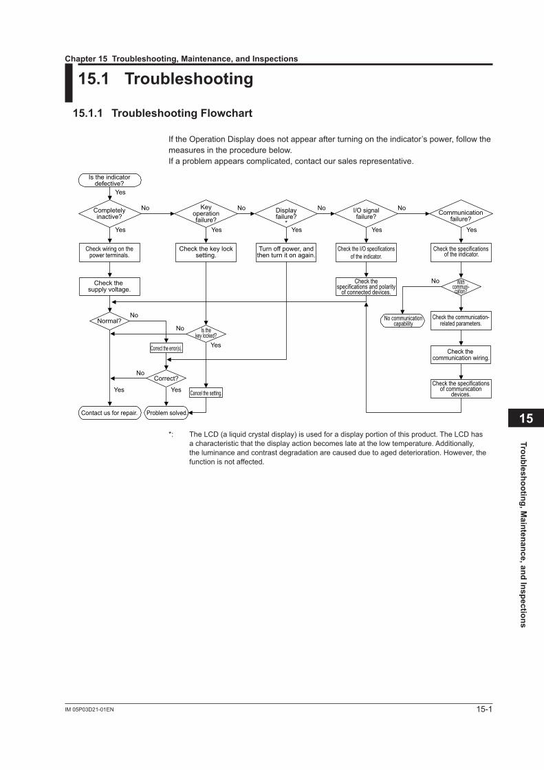
15-1IM 05P03D21-01EN
Troubleshooting, Maintenance, and Inspections
15
15.1 Troubleshooting
15.1.1 Troubleshooting Flowchart
If the Operation Display does not appear after turning on the indicator’s power, follow the measures in the procedure below.If a problem appears complicated, contact our sales representative.
Is the indicatordefective?
Contact us for repair. Problem solved.
No communicationcapability
Completelyinactive?
Yes
Yes
Yes
No
No
No
Keyoperationfailure?
Yes
No
Yes
Check wiring on thepower terminals.
Check the key locksetting.
Displayfailure?
*Yes
No
Turn off power, andthen turn it on again.
I/O signalfailure?
Yes
No
Check the I/O specificationsof the indicator.
Check the supply voltage.
Check thespecifications and polarity
of connected devices.
Check the communication-related parameters.
Check the specificationsof communication
devices.
Check the communication wiring.
Communicationfailure?
No Withcommuni-
cation?
Yes
Normal?Is the
key locked?
Check the specifications of the indicator.
Yes
NoCorrect?
Correct the error(s).
Cancel the setting.
*: The LCD (a liquid crystal display) is used for a display portion of this product. The LCD has a characteristic that the display action becomes late at the low temperature. Additionally, the luminance and contrast degradation are caused due to aged deterioration. However, the function is not affected.
Chapter 15 Troubleshooting, Maintenance, and Inspections
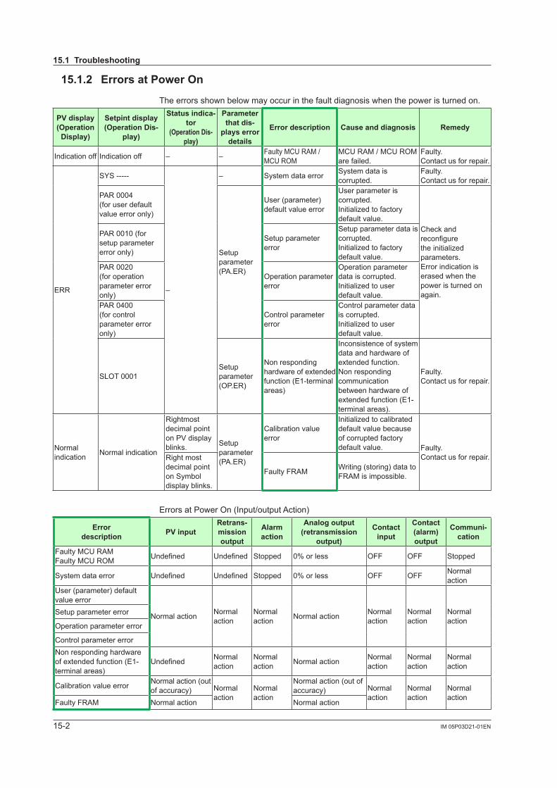
15-2 IM 05P03D21-01EN
15.1 Troubleshooting
15.1.2 Errors at Power On
The errors shown below may occur in the fault diagnosis when the power is turned on.
PV display (Operation
Display)
Setpint display (Operation Dis-
play)
Status indica-tor
(Operation Dis-play)
Parameter that dis-
plays error details
Error description Cause and diagnosis Remedy
Indication off Indication off – – Faulty MCU RAM / MCU ROM
MCU RAM / MCU ROM are failed.
Faulty.Contact us for repair.
ERR
SYS -----
–
– System data error System data is corrupted.
Faulty.Contact us for repair.
PAR 0004(for user default value error only)
Setup parameter (PA.ER)
User (parameter) default value error
User parameter is corrupted.Initialized to factory default value.
Check and reconfigurethe initialized parameters.Error indication is erased when the power is turned on again.
PAR 0010 (for setup parameter error only)
Setup parameter error
Setup parameter data is corrupted.Initialized to factory default value.
PAR 0020 (for operation parameter error only)
Operation parameter error
Operation parameter data is corrupted.Initialized to user default value.
PAR 0400 (for control parameter error only)
Control parameter error
Control parameter data is corrupted.Initialized to user default value.
SLOT 0001Setup parameter (OP.ER)
Non responding hardware of extended function (E1-terminal areas)
Inconsistence of system data and hardware of extended function.Non responding communication between hardware of extended function (E1-terminal areas).
Faulty.Contact us for repair.
Normal indication Normal indication
Rightmost decimal point onPVdisplayblinks. Setup
parameter (PA.ER)
Calibration value error
Initialized to calibrated default value because of corrupted factory default value. Faulty.
Contact us for repair.Right most decimal point on Symbol display blinks.
Faulty FRAM Writing (storing) data to FRAM is impossible.
Errors at Power On (Input/output Action)
Error description PV input
Retrans-mission output
Alarm action
Analog output (retransmission
output)
Contact input
Contact (alarm) output
Communi-cation
Faulty MCU RAMFaulty MCU ROM Undefined Undefined Stopped 0%orless OFF OFF Stopped
System data error Undefined Undefined Stopped 0%orless OFF OFF Normal action
User (parameter) default value error
Normal action Normal action
Normal action Normal action Normal
actionNormal action
Normal action
Setup parameter error
Operation parameter error
Control parameter errorNon responding hardware of extended function (E1-terminal areas)
Undefined Normal action
Normal action Normal action Normal
actionNormal action
Normal action
Calibration value error Normal action (out of accuracy) Normal
actionNormal action
Normal action (out of accuracy) Normal
actionNormal action
Normal action
Faulty FRAM Normal action Normal action
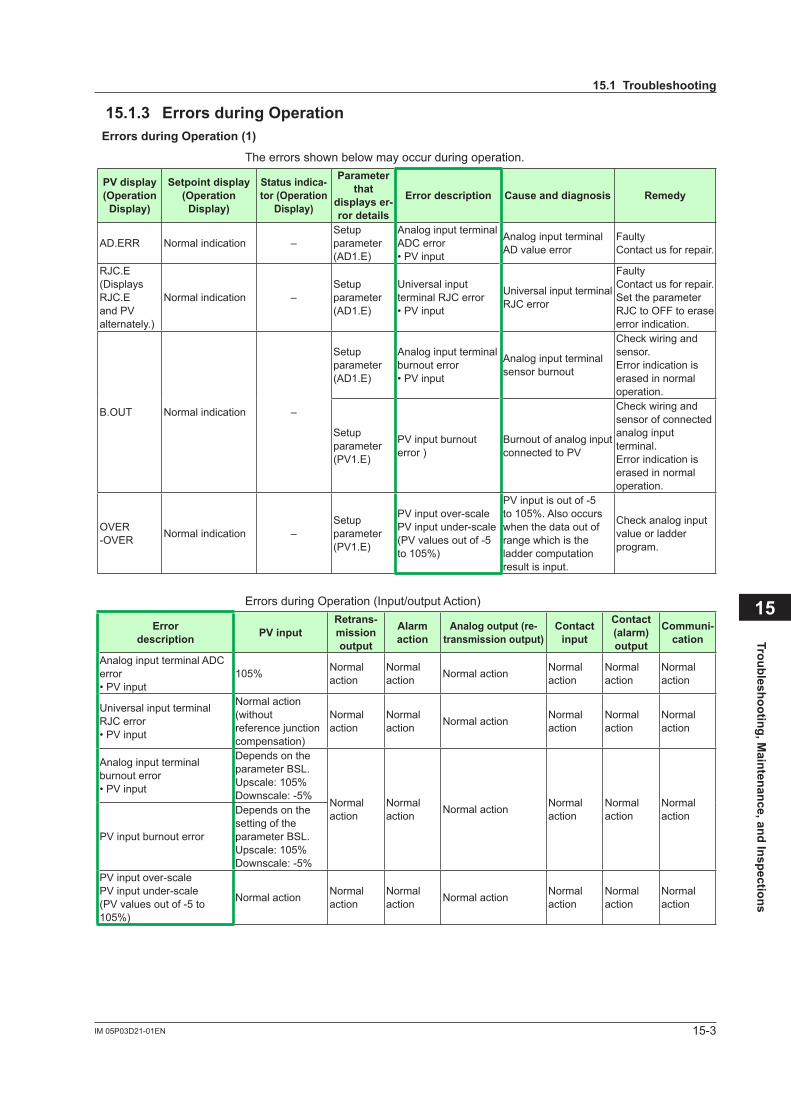
15-3IM 05P03D21-01EN
Troubleshooting, Maintenance, and Inspections
15
15.1 Troubleshooting
15.1.3 Errors during OperationErrors during Operation (1)
The errors shown below may occur during operation.
PV display (Operation
Display)
Setpoint display (Operation
Display)
Status indica-tor (Operation
Display)
Parameter that
displays er-ror details
Error description Cause and diagnosis Remedy
AD.ERR Normal indication –Setup parameter (AD1.E)
Analog input terminal ADC error•PVinput
Analog input terminal AD value error
FaultyContact us for repair.
RJC.E (Displays RJC.E andPValternately.)
Normal indication –Setup parameter (AD1.E)
Universal input terminal RJC error•PVinput
Universal input terminal RJC error
FaultyContact us for repair.Set the parameter RJC to OFF to erase error indication.
B.OUT Normal indication –
Setup parameter (AD1.E)
Analog input terminal burnout error•PVinput
Analog input terminal sensor burnout
Check wiring and sensor.Error indication is erased in normal operation.
Setup parameter (PV1.E)
PVinputburnouterror )
Burnout of analog input connectedtoPV
Check wiring and sensor of connected analog input terminal.Error indication is erased in normal operation.
OVER-OVER Normal indication –
Setup parameter (PV1.E)
PVinputover-scalePVinputunder-scale(PVvaluesoutof-5to105%)
PVinputisoutof-5to105%.Alsooccurswhen the data out of range which is the ladder computation result is input.
Check analog input value or ladder program.
Errors during Operation (Input/output Action)
Error description PV input
Retrans-mission output
Alarm action
Analog output (re-transmission output)
Contact input
Contact (alarm) output
Communi-cation
Analog input terminal ADC error•PVinput
105% Normal action
Normal action Normal action Normal
actionNormal action
Normal action
Universal input terminal RJC error•PVinput
Normal action(without referencejunctioncompensation)
Normal action
Normal action Normal action Normal
actionNormal action
Normal action
Analog input terminal burnout error•PVinput
Depends on the parameter BSL.Upscale:105%Downscale:-5%
Normal action
Normal action Normal action Normal
actionNormal action
Normal action
PVinputburnouterror
Depends on the setting of the parameter BSL.Upscale:105%Downscale:-5%
PVinputover-scalePVinputunder-scale(PVvaluesoutof-5to105%)
Normal action Normal action
Normal action Normal action Normal
actionNormal action
Normal action
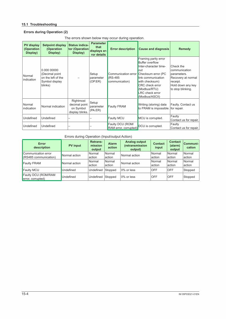
15-4 IM 05P03D21-01EN
15.1 Troubleshooting
Errors during Operation (2)
The errors shown below may occur during operation.
PV display (Operation
Display)
Setpoint display (Operation
Display)
Status indica-tor (Operation
Display)
Parameter that
displays er-ror details
Error description Cause and diagnosis Remedy
Normal indication
0.000 00000(Decimal point on the left of the Symbol display blinks)
–Setup parameter (OP.ER)
Communication error (RS-485 communication)
Framing parity errorBufferoverflowInter-character time-outChecksum error (PC link communication with checksum)CRC check error (Modbus/RTU)LRC check error (Modbus/ASCII)
Check the communication parameters.Recovery at normal receipt.Hold down any key to stop blinking.
Normal indication Normal indication
Rightmost decimal point
on Symbol display blinks.
Setup parameter (PA.ER)
Faulty FRAM Writing (storing) data to FRAM is impossible.
Faulty. Contact us for repair.
Undefined Undefined – – Faulty MCU MCU is corrupted. Faulty Contact us for repair.
Undefined Undefined – – Faulty DCU (ROM/RAM error, corrupted) DCU is corrupted. Faulty
Contact us for repair.
Errors during Operation (Input/output Action)
Error description PV input
Retrans-mission output
Alarm action
Analog output (retransmission
output)
Contact input
Contact (alarm) output
Communi-cation
Communication error (RS485 communication) Normal action Normal
actionNormal action Normal action Normal
actionNormal action
Normal action
Faulty FRAM Normal action Normal action
Normal action Normal action Normal
actionNormal action
Normal action
Faulty MCU Undefined Undefined Stopped 0%orless OFF OFF StoppedFaulty DCU (ROM/RAM error, corrupted) Undefined Undefined Stopped 0%orless OFF OFF Stopped
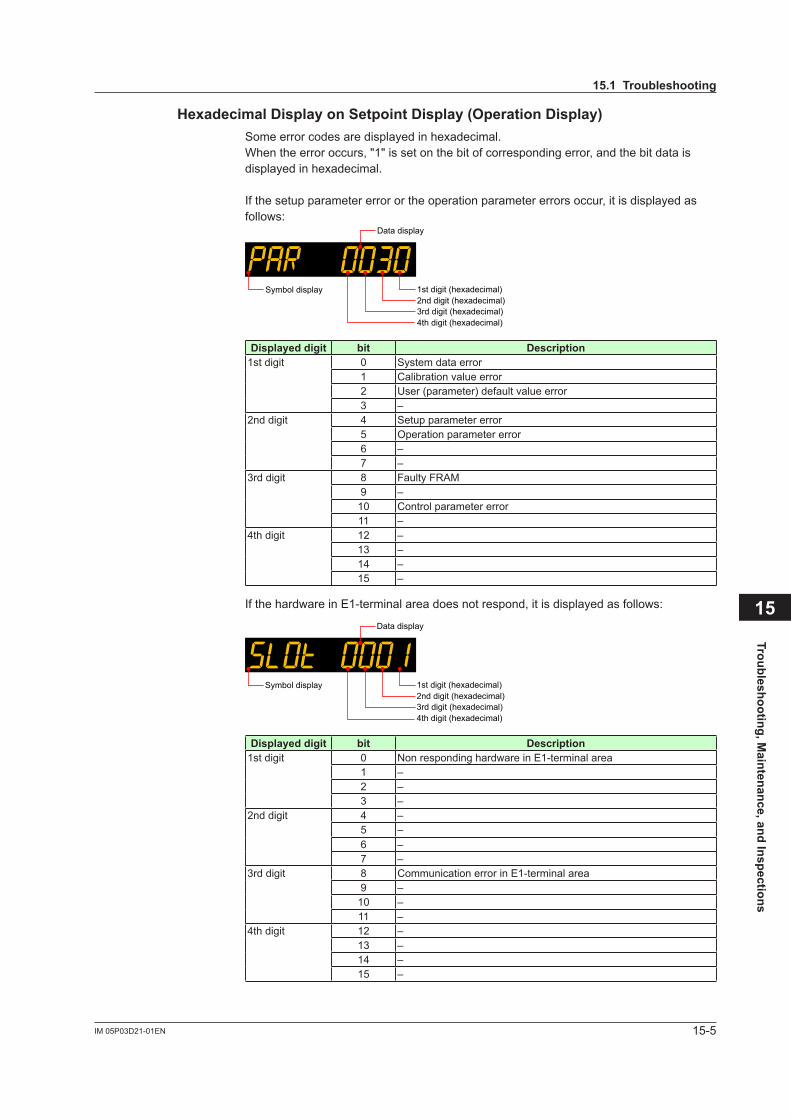
15-5IM 05P03D21-01EN
Troubleshooting, Maintenance, and Inspections
15
15.1 Troubleshooting
Hexadecimal Display on Setpoint Display (Operation Display)Some error codes are displayed in hexadecimal.When the error occurs, "1" is set on the bit of corresponding error, and the bit data is displayed in hexadecimal.
If the setup parameter error or the operation parameter errors occur, it is displayed as follows:
Data display
1st digit (hexadecimal)2nd digit (hexadecimal)3rd digit (hexadecimal)4th digit (hexadecimal)
Symbol display
Displayed digit bit Description1st digit 0 System data error
1 Calibration value error2 User (parameter) default value error3 –
2nd digit 4 Setup parameter error5 Operation parameter error6 –7 –
3rd digit 8 Faulty FRAM9 –10 Control parameter error11 –
4th digit 12 –13 –14 –15 –
If the hardware in E1-terminal area does not respond, it is displayed as follows:
Data display
1st digit (hexadecimal)2nd digit (hexadecimal)3rd digit (hexadecimal)4th digit (hexadecimal)
Symbol display
Displayed digit bit Description1st digit 0 Non responding hardware in E1-terminal area
1 –2 –3 –
2nd digit 4 –5 –6 –7 –
3rd digit 8 Communication error in E1-terminal area9 –10 –11 –
4th digit 12 –13 –14 –15 –
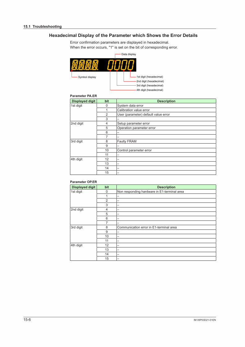
15-6 IM 05P03D21-01EN
15.1 Troubleshooting
Hexadecimal Display of the Parameter which Shows the Error DetailsError confirmation parameters are displayed in hexadecimal.When the error occurs, "1" is set on the bit of corresponding error.
Data display
1st digit (hexadecimal)
2nd digit (hexadecimal)3rd digit (hexadecimal)
4th digit (hexadecimal)
Symbol display
Parameter PA.ERDisplayed digit bit Description
1st digit 0 System data error1 Calibration value error2 User (parameter) default value error3 –
2nd digit 4 Setup parameter error5 Operation parameter error6 –7 –
3rd digit 8 Faulty FRAM9 –10 Control parameter error11 –
4th digit 12 –13 –14 –15 –
Parameter OP.ER Displayed digit bit Description
1st digit 0 Non responding hardware in E1-terminal area1 –2 –3 –
2nd digit 4 –5 –6 –7 –
3rd digit 8 Communication error in E1-terminal area9 –10 –11 –
4th digit 12 –13 –14 –15 –
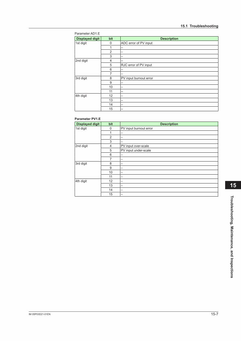
15-7IM 05P03D21-01EN
Troubleshooting, Maintenance, and Inspections
15
15.1 Troubleshooting
Parameter AD1.E Displayed digit bit Description
1st digit 0 ADCerrorofPVinput1 –2 –3 –
2nd digit 4 –5 RJCerrorofPVinput6 –7 –
3rd digit 8 PVinputburnouterror9 –10 –11 –
4th digit 12 –13 –14 –15 –
Parameter PV1.E Displayed digit bit Description
1st digit 0 PVinputburnouterror1 –2 –3 –
2nd digit 4 PVinputover-scale5 PVinputunder-scale6 –7 –
3rd digit 8 –9 –10 –11 –
4th digit 12 –13 –14 –15 –
15-8 IM 05P03D21-01EN
15.2 Maintenance
15.2.1 CleaningThe front panel and operation keys should be gently wiped with a cloth soaked with water and squeezed firmly.
CAUTIONIn order to prevent LCD from static electricity damage, do not wipe with dry cloth. (When LCD is electrified, it returns to normal in several minutes.) Do not use alcohol, benzene, or any other solvents.
15.2.2 Packaging when Shipping the Product for RepairShould the instrument break down and need to be shipped to our sales representative for repair, handle it as noted below:
CAUTIONWrite down the settings of parameters for a repair request.
WARNINGPrior to shipping the instrument, put it into an antistatic bag and repackage it using the original internal packaging materials and packaging container.
15.2.3 Replacing PartsDo not replace any parts inside the unit.
15-9IM 05P03D21-01EN
Troubleshooting, Maintenance, and Inspections
15
15.3 Periodic Maintenance
Check the operating condition periodically to use this instrument with good condition.
15-10 IM 05P03D21-01EN
15.4 Disposal
When disposing of this instrument, arrange for appropriate disposal as industrial waste according to the rules of a country, the area, or a local government.
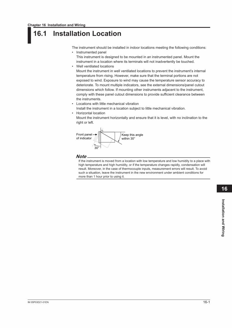
Installation and Wiring
16
16-1IM 05P03D21-01EN
16.1 Installation Location
The instrument should be installed in indoor locations meeting the following conditions:• Instrumented panel This instrument is designed to be mounted in an instrumented panel. Mount the
instrument in a location where its terminals will not inadvertently be touched.• Well ventilated locations Mount the instrument in well ventilated locations to prevent the instrument’s internal
temperature from rising. However, make sure that the terminal portions are not exposed to wind. Exposure to wind may cause the temperature sensor accuracy to deteriorate. To mount multiple indicators, see the external dimensions/panel cutout dimensionswhichfollow.Ifmountingotherinstrumentsadjacenttotheinstrument,comply with these panel cutout dimensions to provide sufficient clearance between the instruments.
• Locations with little mechanical vibration Installtheinstrumentinalocationsubjecttolittlemechanicalvibration.• Horizontal location Mount the instrument horizontally and ensure that it is level, with no inclination to the
right or left.
Front panelof indicator
Keep this anglewithin 30°
30°
NoteIf the instrument is moved from a location with low temperature and low humidity to a place with high temperature and high humidity, or if the temperature changes rapidly, condensation will result. Moreover, in the case of thermocouple inputs, measurement errors will result. To avoid such a situation, leave the instrument in the new environment under ambient conditions for more than 1 hour prior to using it.
Chapter 16 Installation and Wiring
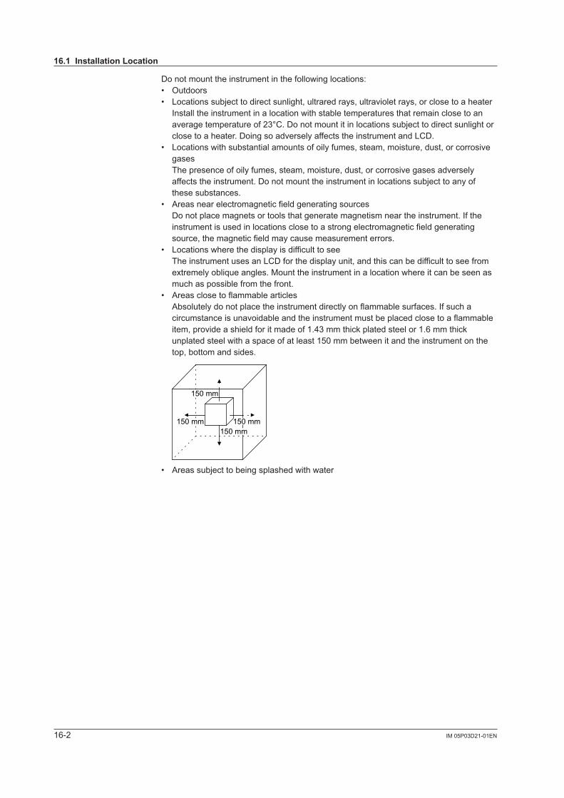
16-2 IM 05P03D21-01EN
Do not mount the instrument in the following locations:• Outdoors• Locationssubjecttodirectsunlight,ultraredrays,ultravioletrays,orclosetoaheater Install the instrument in a location with stable temperatures that remain close to an
averagetemperatureof23°C.Donotmountitinlocationssubjecttodirectsunlightorclose to a heater. Doing so adversely affects the instrument and LCD.
• Locations with substantial amounts of oily fumes, steam, moisture, dust, or corrosive gases
The presence of oily fumes, steam, moisture, dust, or corrosive gases adversely affectstheinstrument.Donotmounttheinstrumentinlocationssubjecttoanyofthese substances.
• Areas near electromagnetic field generating sources Do not place magnets or tools that generate magnetism near the instrument. If the
instrument is used in locations close to a strong electromagnetic field generating source, the magnetic field may cause measurement errors.
• Locations where the display is difficult to see The instrument uses an LCD for the display unit, and this can be difficult to see from
extremely oblique angles. Mount the instrument in a location where it can be seen as much as possible from the front.
• Areas close to flammable articles Absolutely do not place the instrument directly on flammable surfaces. If such a
circumstance is unavoidable and the instrument must be placed close to a flammable item, provide a shield for it made of 1.43 mm thick plated steel or 1.6 mm thick unplated steel with a space of at least 150 mm between it and the instrument on the top, bottom and sides.
150 mm150 mm
150 mm
150 mm
• Areassubjecttobeingsplashedwithwater
16.1 Installation Location
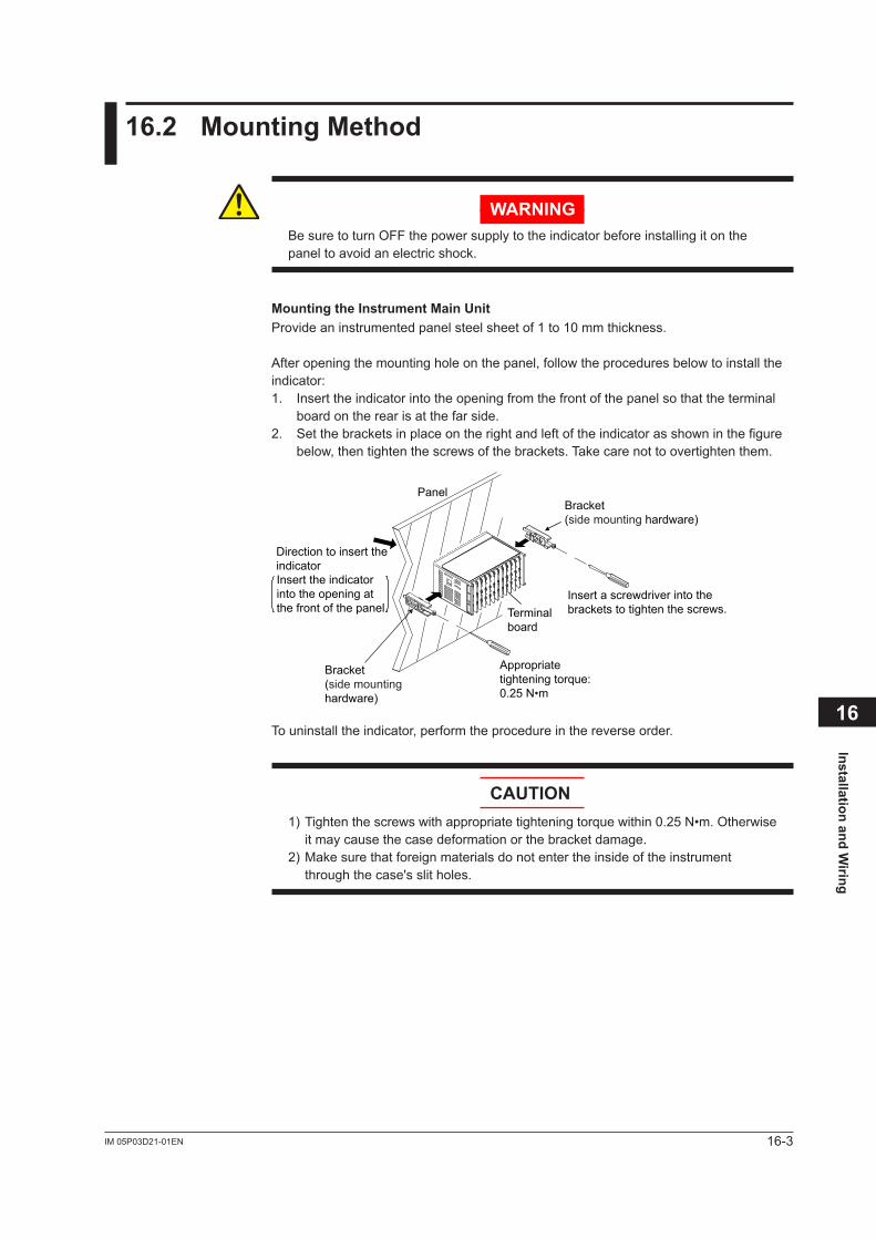
Installation and Wiring
16
16-3IM 05P03D21-01EN
16.2 Mounting Method
WARNINGBe sure to turn OFF the power supply to the indicator before installing it on the panel to avoid an electric shock.
Mounting the Instrument Main UnitProvide an instrumented panel steel sheet of 1 to 10 mm thickness.
After opening the mounting hole on the panel, follow the procedures below to install the indicator:1. Insert the indicator into the opening from the front of the panel so that the terminal
board on the rear is at the far side.2. Set the brackets in place on the right and left of the indicator as shown in the figure
below, then tighten the screws of the brackets. Take care not to overtighten them.
Terminal board
Bracket(side mountinghardware)
Panel
Insert a screwdriver into thebrackets to tighten the screws.
Appropriatetightening torque:0.25 N•m
Direction to insert theindicatorInsert the indicatorinto the opening atthe front of the panel.
Bracket(side mounting hardware)
To uninstall the indicator, perform the procedure in the reverse order.
CAUTION1) Tighten the screws with appropriate tightening torque within 0.25 N•m. Otherwise
it may cause the case deformation or the bracket damage.2) Make sure that foreign materials do not enter the inside of the instrument
through the case's slit holes.
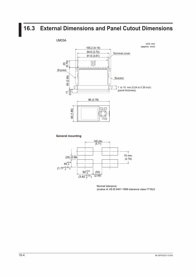
16-4 IM 05P03D21-01EN
16.3 External Dimensions and Panel Cutout Dimensions
Normal tolerance: ±(value of JIS B 0401-1998 tolerance class IT18)/2
11 (0.43
)65
(2.5
6)48
(1.8
9)
20(0
.79)
96 (3.78)
145 min.(5.71)
UM33A
94.6 (3.72)91.6 (3.61)
105.2 (4.14)Unit: mm
(approx. inch)
Bracket
Bracket
Terminal cover
1 to 10 mm (0.04 to 0.39 inch) (panel thickness)
General mounting
(53)(2.09)
(25) (0.98)
+0.8092
+0.030(3.62 )
70 min.(2.76)
+0.6045
+0.020(1.77 )
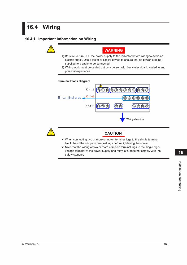
Installation and Wiring
16
16-5IM 05P03D21-01EN
16.4 Wiring
16.4.1 Important Information on Wiring
WARNING1) Be sure to turn OFF the power supply to the indicator before wiring to avoid an
electric shock. Use a tester or similar device to ensure that no power is being supplied to a cable to be connected.
2) Wiring work must be carried out by a person with basic electrical knowledge and practical experience.
Terminal Block Diagram
E1-terminal area 301-306
201-212
101-112
306 305 304 303 302 301
212 211 210 208 207 204 203
112 111 110 109 106 105 104108 107 103
202 201
102 101
Wiring direction
CAUTION Whenconnectingtwoormorecrimp-onterminallugstothesingleterminal
block, bend the crimp-on terminal lugs before tightening the screw. Notethatthewiringoftwoormorecrimp-onterminallugstothesinglehigh-
voltage terminal of the power supply and relay, etc. does not comply with the safety standard.
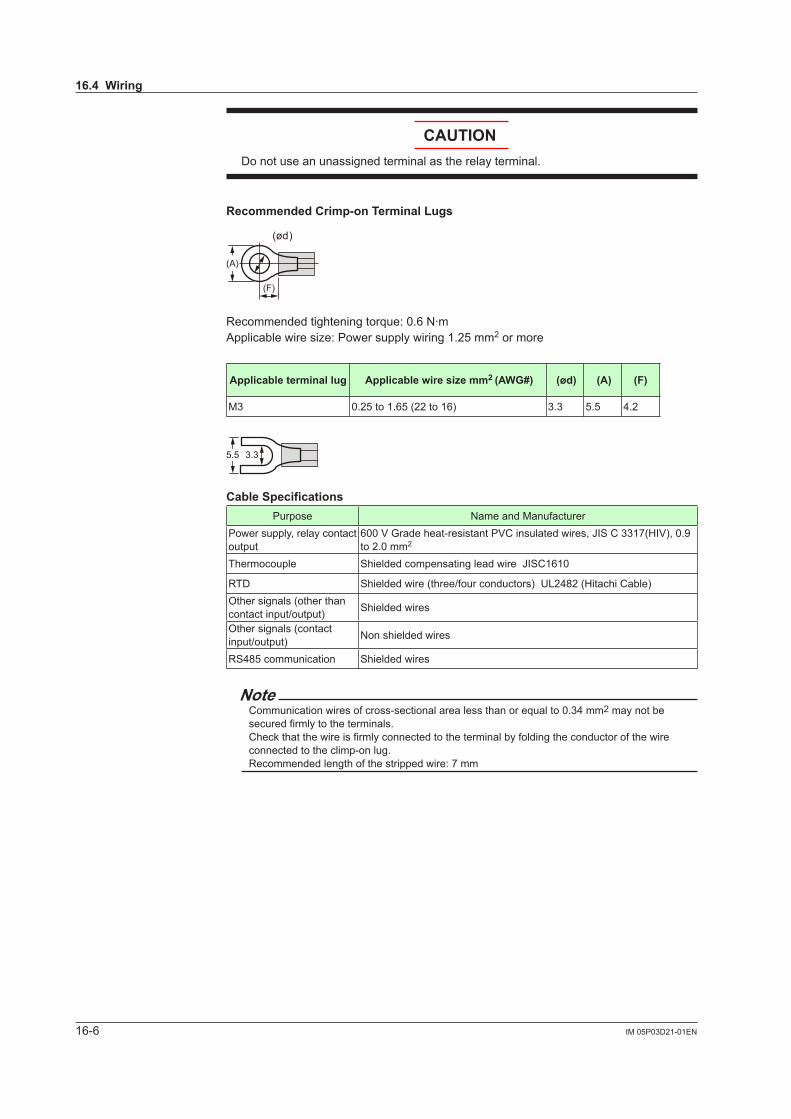
16-6 IM 05P03D21-01EN
CAUTIONDo not use an unassigned terminal as the relay terminal.
Recommended Crimp-on Terminal Lugs
(A)
(F)
(ød)
Recommended tightening torque: 0.6 N·mApplicable wire size: Power supply wiring 1.25 mm2 or more
Applicable terminal lug Applicable wire size mm2 (AWG#) (ød) (A) (F)
M3 0.25 to 1.65 (22 to 16) 3.3 5.5 4.2
5.5 3.3
Cable SpecificationsPurpose Name and Manufacturer
Power supply, relay contact output
600VGradeheat-resistantPVCinsulatedwires,JISC3317(HIV),0.9to 2.0 mm2
Thermocouple Shielded compensating lead wire JISC1610
RTD Shielded wire (three/four conductors) UL2482 (Hitachi Cable)Other signals (other than contact input/output) Shielded wires
Other signals (contact input/output) Non shielded wires
RS485 communication Shielded wires
NoteCommunication wires of cross-sectional area less than or equal to 0.34 mm2 may not be secured firmly to the terminals.Check that the wire is firmly connected to the terminal by folding the conductor of the wire connected to the climp-on lug.Recommended length of the stripped wire: 7 mm
16.4 Wiring
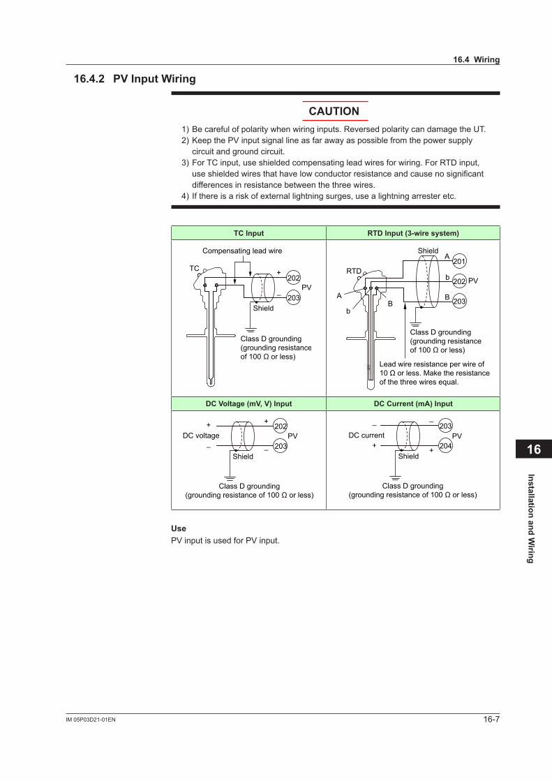
Installation and Wiring
16
16-7IM 05P03D21-01EN
16.4.2 PV Input Wiring
CAUTION1) Be careful of polarity when wiring inputs. Reversed polarity can damage the UT.2)KeepthePVinputsignallineasfarawayaspossiblefromthepowersupply
circuit and ground circuit.3) For TC input, use shielded compensating lead wires for wiring. For RTD input,
use shielded wires that have low conductor resistance and cause no significant differences in resistance between the three wires.
4) If there is a risk of external lightning surges, use a lightning arrester etc.
TC Input RTD Input (3-wire system)
203
202TC
–
+
Compensating lead wire
Class D grounding(grounding resistanceof 100 Ω or less)
Shield
PV
203
202
201RTD
A
B
b
Lead wire resistance per wire of10 Ω or less. Make the resistanceof the three wires equal.
A
bB
Class D grounding(grounding resistanceof 100 Ω or less)
Shield
PV
DC Voltage (mV, V) Input DC Current (mA) Input
203
202
–
++
–DC voltage
Class D grounding(grounding resistance of 100 Ω or less)
Shield
PV204
203–
++
–DC current
Class D grounding(grounding resistance of 100 Ω or less)
Shield
PV
UsePVinputisusedforPVinput.
16.4 Wiring
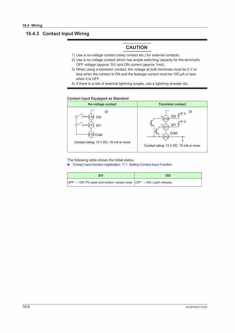
16-8 IM 05P03D21-01EN
16.4.3 Contact Input Wiring
CAUTION1) Use a no-voltage contact (relay contact etc.) for external contacts.2) Use a no-voltage contact which has ample switching capacity for the terminal's
OFFvoltage(approx.5V)andONcurrent(approx1mA).3)Whenusingatransistorcontact,thevoltageatbothterminalsmustbe2Vor
less when the contact is ON and the leakage current must be 100 µA or less when it is OFF.
4) If there is a risk of external lightning surges, use a lightning arrester etc.
Contact Input Equipped as StandardNo-voltage contact Transistor contact
DI2
DI1
COM
210
211
212
DI
Contact rating: 12 V DC, 10 mA or more
DI2
DI1
COM
210
211
212
DI+
+
–
+5 V
+5 V
Contact rating: 12 V DC, 10 mA or more
The following table shows the initial status. Contact input function registration: 11.1 Setting Contact Input Function
DI1 DI2
OFF→ON:PVpeakandbottomvaluesreset OFF→ON:Latchrelease
16.4 Wiring
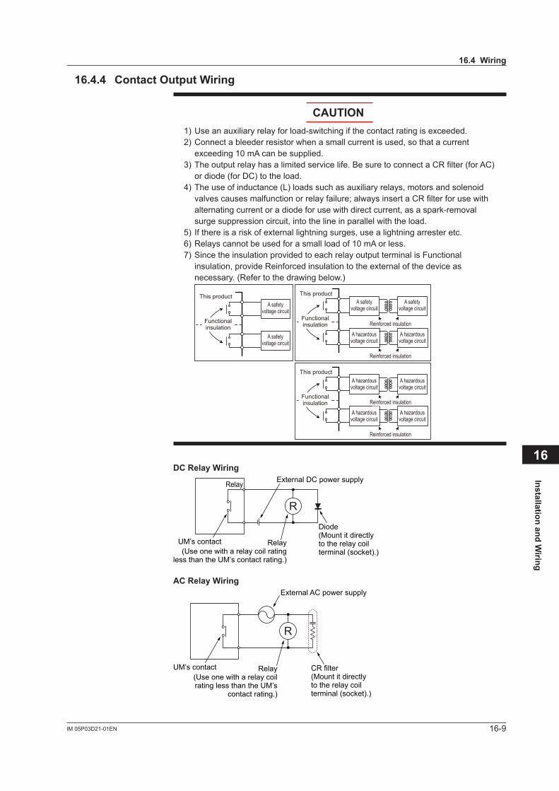
Installation and Wiring
16
16-9IM 05P03D21-01EN
16.4.4 Contact Output Wiring
CAUTION1) Use an auxiliary relay for load-switching if the contact rating is exceeded.2) Connect a bleeder resistor when a small current is used, so that a current
exceeding 10 mA can be supplied.3) The output relay has a limited service life. Be sure to connect a CR filter (for AC)
or diode (for DC) to the load.4) The use of inductance (L) loads such as auxiliary relays, motors and solenoid
valves causes malfunction or relay failure; always insert a CR filter for use with alternating current or a diode for use with direct current, as a spark-removal surge suppression circuit, into the line in parallel with the load.
5) If there is a risk of external lightning surges, use a lightning arrester etc.6) Relays cannot be used for a small load of 10 mA or less.7) Since the insulation provided to each relay output terminal is Functional
insulation, provide Reinforced insulation to the external of the device as necessary. (Refer to the drawing below.)
This product
Functionalinsulation
A safety voltage circuit
A safety voltage circuit
This product
Reinforced insulation
Reinforced insulation
Functionalinsulation
A hazardous voltage circuit
A hazardous voltage circuit
A safety voltage circuit
A safety voltage circuit
This product
Reinforced insulation
Reinforced insulation
Functionalinsulation
A hazardous voltage circuit
A hazardous voltage circuit
A hazardous voltage circuit
A hazardous voltage circuit
DC Relay Wiring
R
External DC power supplyRelay
UM’s contact
Diode(Mount it directlyto the relay coilterminal (socket).)
Relay(Use one with a relay coil rating
less than the UM’s contact rating.)
AC Relay Wiring
R
CR filter(Mount it directlyto the relay coilterminal (socket).)
Relay(Use one with a relay coilrating less than the UM’s
contact rating.)
UM’s contact
External AC power supply
16.4 Wiring
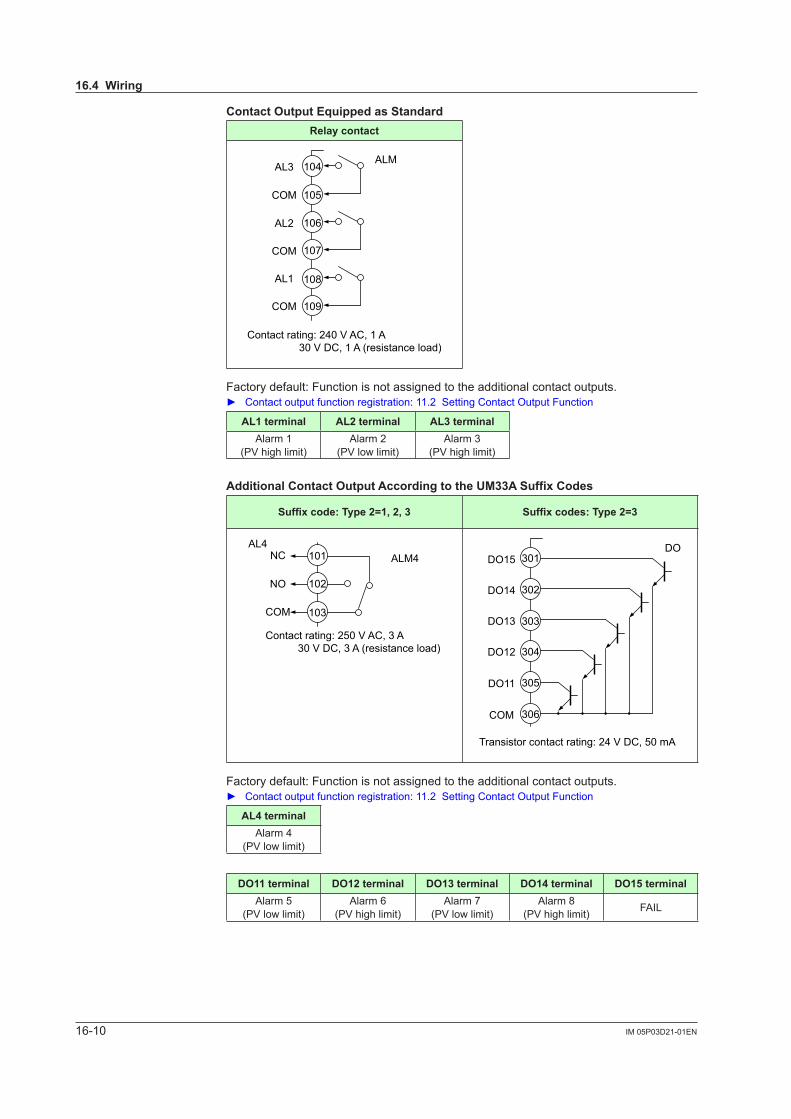
16-10 IM 05P03D21-01EN
Contact Output Equipped as StandardRelay contact
AL3
AL2
AL1
COM
COM
COM
Contact rating: 240 V AC, 1 A 30 V DC, 1 A (resistance load)
104
105
106
107
108
109
ALM
Factory default: Function is not assigned to the additional contact outputs. Contact output function registration: 11.2 Setting Contact Output Function
AL1 terminal AL2 terminal AL3 terminalAlarm 1
(PVhighlimit)Alarm 2
(PVlowlimit)Alarm 3
(PVhighlimit)
Additional Contact Output According to the UM33A Suffix Codes
Suffixcode:Type2=1,2,3 Suffixcodes:Type2=3
NC
NO
COM
101
102
103
ALM4AL4
Contact rating: 250 V AC, 3 A 30 V DC, 3 A (resistance load)
Transistor contact rating: 24 V DC, 50 mA
DO12
DO11
DO13
DO14
DO15
COM
301
302
303
304
305
306
DO
Factory default: Function is not assigned to the additional contact outputs. Contact output function registration: 11.2 Setting Contact Output Function
AL4 terminalAlarm 4
(PVlowlimit)
DO11 terminal DO12 terminal DO13 terminal DO14 terminal DO15 terminalAlarm 5
(PVlowlimit)Alarm 6
(PVhighlimit)Alarm 7
(PVlowlimit)Alarm 8
(PVhighlimit) FAIL
16.4 Wiring
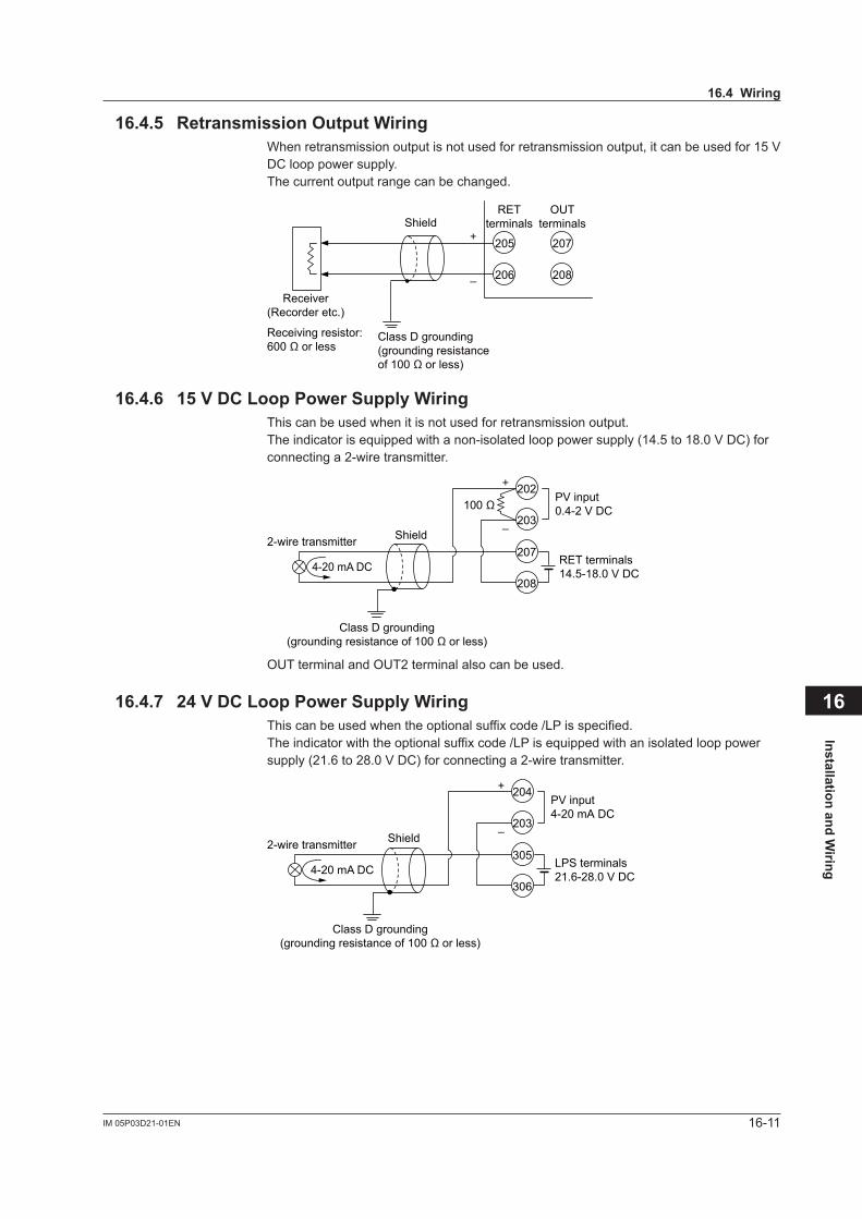
Installation and Wiring
16
16-11IM 05P03D21-01EN
16.4.5 Retransmission Output Wiring Whenretransmissionoutputisnotusedforretransmissionoutput,itcanbeusedfor15VDC loop power supply.The current output range can be changed.
206
205
208
207
Class D grounding(grounding resistanceof 100 Ω or less)
OUTterminals
RETterminalsShield
–
+
Receiver(Recorder etc.)
Receiving resistor:600 Ω or less
16.4.6 15 V DC Loop Power Supply WiringThis can be used when it is not used for retransmission output.Theindicatorisequippedwithanon-isolatedlooppowersupply(14.5to18.0VDC)forconnecting a 2-wire transmitter.
Class D grounding(grounding resistance of 100 Ω or less)
PV input0.4-2 V DC
Shield –
+
2-wire transmitterRET terminals14.5-18.0 V DC
100 Ω
208
207
203
202
4-20 mA DC
OUT terminal and OUT2 terminal also can be used.
16.4.7 24 V DC Loop Power Supply WiringThis can be used when the optional suffix code /LP is specified. The indicator with the optional suffix code /LP is equipped with an isolated loop power supply(21.6to28.0VDC)forconnectinga2-wiretransmitter.
Class D grounding(grounding resistance of 100 Ω or less)
PV input4-20 mA DC
Shield –
+
2-wire transmitterLPS terminals21.6-28.0 V DC
306
305
203
204
4-20 mA DC
16.4 Wiring
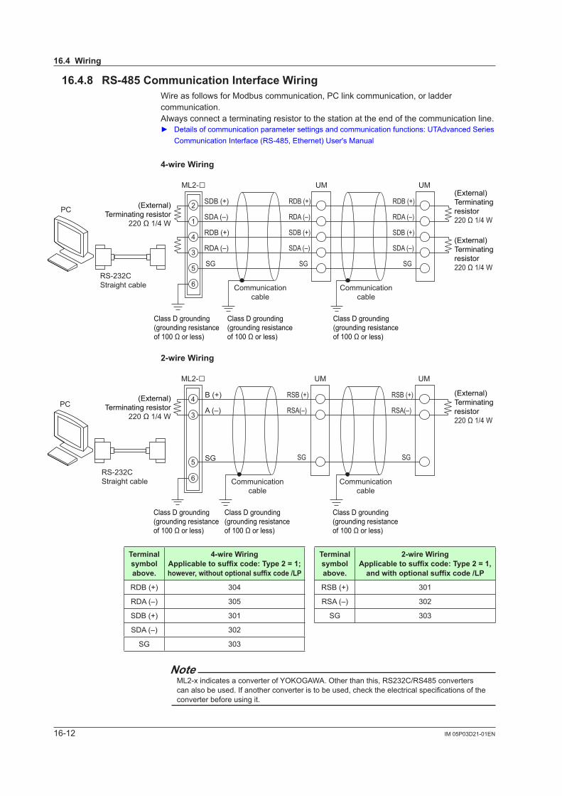
16-12 IM 05P03D21-01EN
16.4.8 RS-485CommunicationInterfaceWiringWire as follows for Modbus communication, PC link communication, or ladder communication.Always connect a terminating resistor to the station at the end of the communication line. Detailsofcommunicationparametersettingsandcommunicationfunctions:UTAdvancedSeries
CommunicationInterface(RS-485,Ethernet)User'sManual
4-wireWiring
ML2-
SG
SDB (+)
SDA (–)
RDB (+)
RDA (–)
RDB (+)
RDA (–)
SDB (+)
SDA (–)
SG
RDB (+)
RDA (–)
SDB (+)
SDA (–)
SGRS-232CStraight cable
UM
2
1
4
3
5
6
UM
Class D grounding(grounding resistanceof 100 Ω or less)
Communicationcable
Class D grounding(grounding resistanceof 100 Ω or less)
Communicationcable
Class D grounding(grounding resistanceof 100 Ω or less)
PC (External)Terminating resistor
220 Ω 1/4 W
(External)Terminating resistor220 Ω 1/4 W
(External)Terminating resistor220 Ω 1/4 W
2-wireWiring
SG
ML2-B (+)
A (–)
RSB (+)
RSA(–)
SG
RSB (+)
RSA(–)
SG
RS-232CStraight cable
PC4
3
5
6
UM UM
Class D grounding(grounding resistanceof 100 Ω or less)
(External)Terminating resistor
220 Ω 1/4 W
(External)Terminating resistor220 Ω 1/4 W
Communicationcable
Class D grounding(grounding resistanceof 100 Ω or less)
Communicationcable
Class D grounding(grounding resistanceof 100 Ω or less)
Terminalsymbolabove.
4-wireWiringApplicable to suffix code: Type 2 = 1; however, without optional suffix code /LP
Terminalsymbolabove.
2-wireWiringApplicable to suffix code: Type 2 = 1,
and with optional suffix code /LP
RDB(+) 304 RSB(+) 301
RDA(–) 305 RSA(–) 302
SDB(+) 301 SG 303
SDA(–) 302
SG 303
NoteML2-xindicatesaconverterofYOKOGAWA.Otherthanthis,RS232C/RS485converterscanalsobeused.Ifanotherconverteristobeused,checktheelectricalspecificationsoftheconverterbeforeusingit.
16.4Wiring
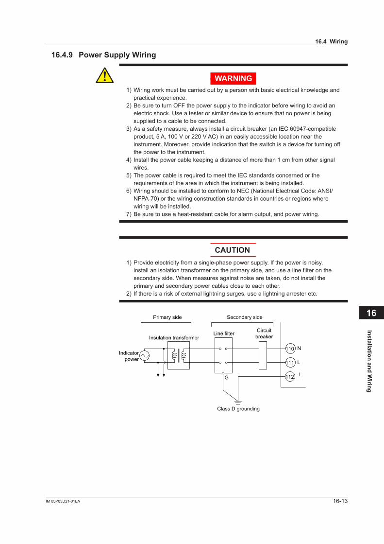
Installation and Wiring
16
16-13IM 05P03D21-01EN
16.4.9 Power Supply Wiring
WARNING1) Wiring work must be carried out by a person with basic electrical knowledge and
practical experience.2) Be sure to turn OFF the power supply to the indicator before wiring to avoid an
electric shock. Use a tester or similar device to ensure that no power is being supplied to a cable to be connected.
3) As a safety measure, always install a circuit breaker (an IEC 60947-compatible product,5A,100Vor220VAC)inaneasilyaccessiblelocationneartheinstrument. Moreover, provide indication that the switch is a device for turning off the power to the instrument.
4) Install the power cable keeping a distance of more than 1 cm from other signal wires.
5) The power cable is required to meet the IEC standards concerned or the requirements of the area in which the instrument is being installed.
6) Wiring should be installed to conform to NEC (National Electrical Code: ANSI/NFPA-70) or the wiring construction standards in countries or regions where wiring will be installed.
7) Be sure to use a heat-resistant cable for alarm output, and power wiring.
CAUTION1) Provide electricity from a single-phase power supply. If the power is noisy,
install an isolation transformer on the primary side, and use a line filter on the secondary side. When measures against noise are taken, do not install the primary and secondary power cables close to each other.
2) If there is a risk of external lightning surges, use a lightning arrester etc.
111
110
L
N
CircuitbreakerLine filter
Insulation transformer
Primary side Secondary side
Indicatorpower
112
Class D grounding
G
16.4 Wiring
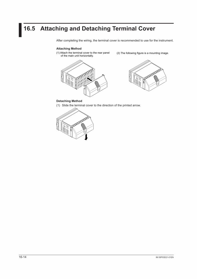
16-14 IM 05P03D21-01EN
16.5 Attaching and Detaching Terminal Cover
After completing the wiring, the terminal cover is recommended to use for the instrument.
Attaching Method
(2) The following figure is a mounting image.(1) Attach the terminal cover to the rear panel of the main unit horizontally.
Detaching Method(1) Slide the terminal cover to the direction of the printed arrow.
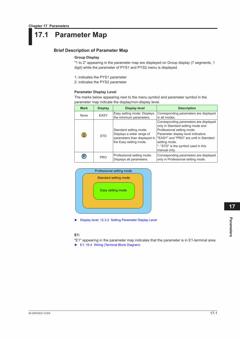
17-1IM 05P03D21-01EN
Parameters
17
17.1 Parameter Map
Brief Description of Parameter MapGroup Display"1 to 2" appearing in the parameter map are displayed on Group display (7 segments, 1 digit) while the parameter of PYS1 and PYS2 menu is displayed.
1: indicates the PYS1 parameter2: indicates the PYS2 parameter
Parameter Display LevelThe marks below appearing next to the menu symbol and parameter symbol in the parameter map indicate the display/non-display level.
Mark Display Display level Description
None EASY Easy setting mode: Displays the minimum parameters.
Corresponding parameters are displayed in all modes.
S STD
Standard setting mode: Displays a wider range of parameters than displayed in the Easy setting mode.
Corresponding parameters are displayed only in Standard setting mode and Professional setting mode.Parameter display level indicators "EASY" and "PRO" are unlit in Standard setting mode.*: "STD" is the symbol used in this manual only.
P PRO Professional setting mode: Displays all parameters.
Corresponding parameters are displayed only in Professional setting mode.
Professional setting mode
Standard setting mode
Easy setting mode
Displaylevel:12.3.2SettingParameterDisplayLevel
E1:"E1" appearing in the parameter map indicates that the parameter is in E1-terminal area. E1: 16.4 Wiring (Terminal Block Diagram)
Chapter 17 Parameters
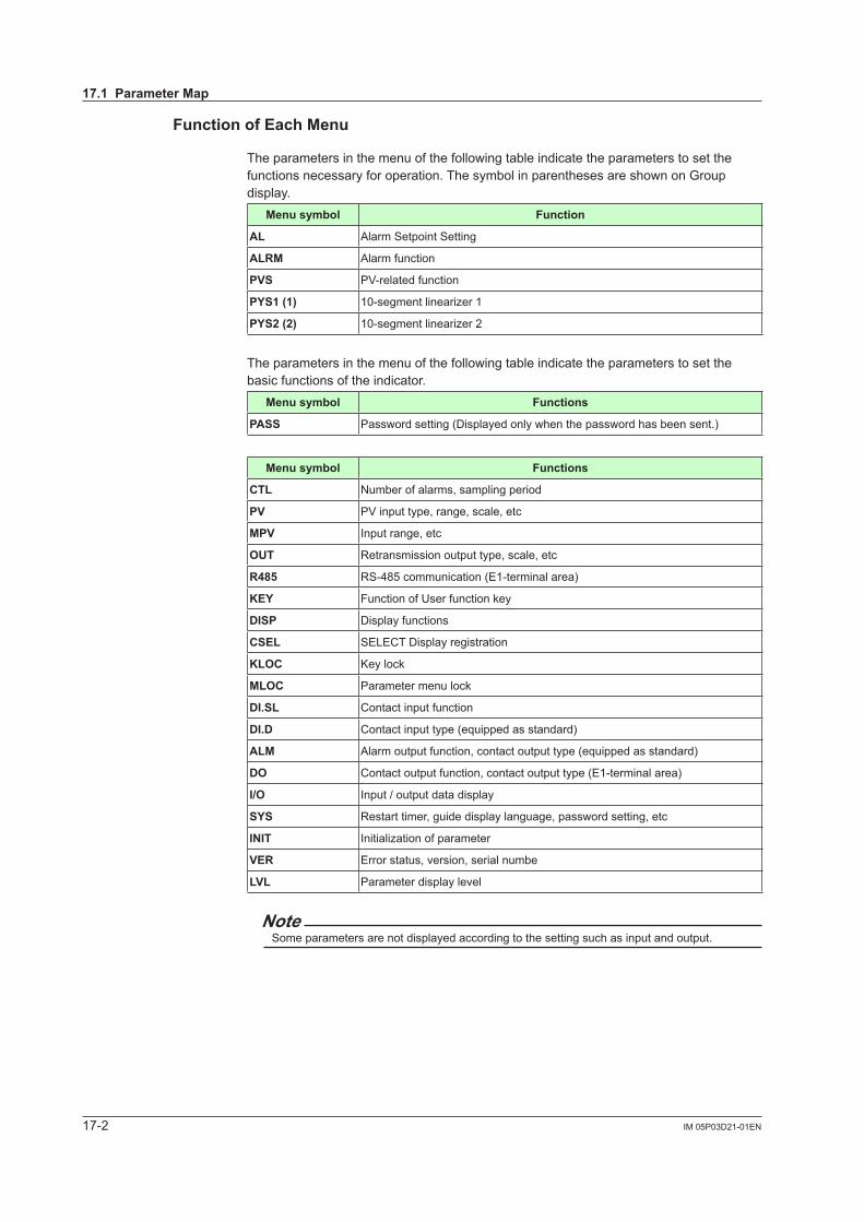
17-2 IM 05P03D21-01EN
Function of Each Menu
The parameters in the menu of the following table indicate the parameters to set the functions necessary for operation. The symbol in parentheses are shown on Group display.
Menu symbol Function
AL Alarm Setpoint Setting
ALRM Alarm function
PVS PV-relatedfunction
PYS1 (1) 10-segment linearizer 1
PYS2 (2) 10-segment linearizer 2
The parameters in the menu of the following table indicate the parameters to set the basic functions of the indicator.
Menu symbol Functions
PASS Password setting (Displayed only when the password has been sent.)
Menu symbol Functions
CTL Number of alarms, sampling period
PV PVinputtype,range,scale,etc
MPV Input range, etc
OUT Retransmission output type, scale, etc
R485 RS-485 communication (E1-terminal area)
KEY Function of User function key
DISP Display functions
CSEL SELECT Display registration
KLOC Key lock
MLOC Parameter menu lock
DI.SL Contact input function
DI.D Contact input type (equipped as standard)
ALM Alarm output function, contact output type (equipped as standard)
DO Contact output function, contact output type (E1-terminal area)
I/O Input / output data display
SYS Restart timer, guide display language, password setting, etc
INIT Initialization of parameter
VER Error status, version, serial numbe
LVL Parameter display level
NoteSome parameters are not displayed according to the setting such as input and output.
17.1 Parameter Map
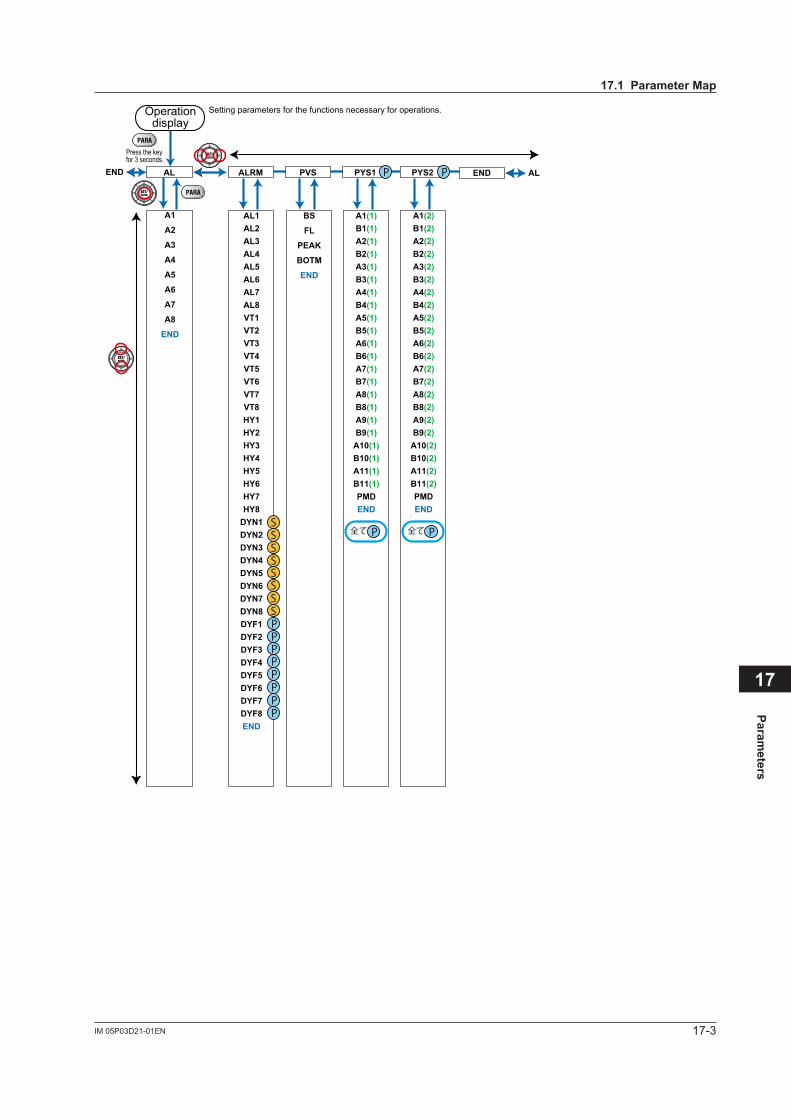
17-3IM 05P03D21-01EN
Parameters
17
AL1AL2AL3AL4AL5AL6AL7AL8VT1VT2VT3VT4VT5VT6VT7VT8HY1HY2HY3HY4HY5HY6HY7HY8
DYN1DYN2DYN3DYN4DYN5DYN6DYN7DYN8DYF1DYF2DYF3DYF4DYF5DYF6DYF7DYF8END
ALRM
A1(1)B1(1)A2(1)B2(1)A3(1)B3(1)A4(1)B4(1)A5(1)B5(1)A6(1)B6(1)A7(1)B7(1)A8(1)B8(1)A9(1)B9(1)
A10(1)B10(1)A11(1)B11(1)PMDEND
PYS1
A1(2)B1(2)A2(2)B2(2)A3(2)B3(2)A4(2)B4(2)A5(2)B5(2)A6(2)B6(2)A7(2)B7(2)A8(2)B8(2)A9(2)B9(2)
A10(2)B10(2)A11(2)B11(2)PMDEND
PYS2
BS
FL
PEAK
BOTM
END
PVSAL ENDEND
A1
A2
A3
A4
A5
A6
A7
A8
END
AL
P
SSSSSSSS
PPPPPPP
P P
P全て P全て
Operationdisplay
Setting parameters for the functions necessary for operations.
Press the keyfor 3 seconds.
17.1 Parameter Map
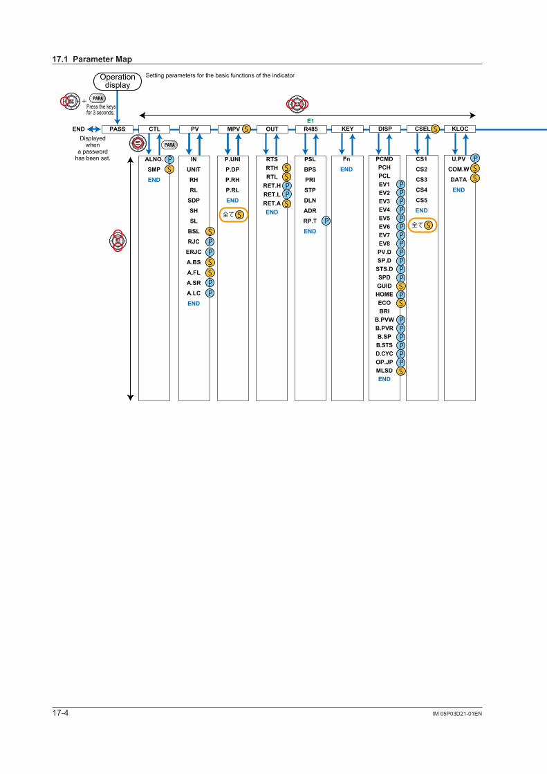
17-4 IM 05P03D21-01EN
IN
UNIT
RH
RL
SDP
SH
SL
BSL
RJC
ERJC
A.BS
A.FL
A.SR
A.LC
END
PSL
BPS
PRI
STP
DLN
ADR
RP.T
END
RTSRTHRTL
RET.HRET.LRET.AEND
DI1.D
DI2.D
END
PA.ER
OP.ER
AD1.E
PV1.E
MCU
DCU
ECU1(E1)
PARA
H.VER
SER1
SER2
END
U.DEF
F.DEF
END
R.TM
C.GRN
FREQ
QSM
LANG
PASS
END
KEY
X000
Y000
Y100(E1)
END
E1PV
P.UNI
P.DP
P.RH
P.RL
END
MPV
ALNO.
SMP
END
CTLPASS R485OUT DI.D VERINITSYSI/O
RST
LAT
LCD
PVRW
MG1
MG2
MG3
MG4
END
DI.SL
LEVL
LVL END
DO1.S
DO2.S
DO3.S
DO4.S
DO5.S
DO1.D
DO2.D
DO3.D
DO4.D
DO5.D
END
AL1.S
AL2.S
AL3.S
AL4.S
AL1.D
AL2.D
AL3.D
AL4.D
END
E1DOALM
+
END
PASSCTLPV
MPVOUT
R485(E1)
KEYDISPCSELKLOCDI.SLDI.DALM
DO(E1)
I/OSYSINITVERLVLAL
ALRMPVS
PYS1PYS2END
U.PV
COM.W
DATA
END
CS1
CS2
CS3
CS4
CS5
END
PCMDPCHPCLEV1EV2EV3EV4EV5EV6EV7EV8PV.DSP.D
STS.DSPDGUIDHOMEECOBRI
B.PVWB.PVRB.SPB.STSD.CYCOP.JPMLSDEND
Fn
END
MLOCKLOCCSELDISPKEY
P
P
PPPPPPP
P
PP
P
P
PPPPPP
P
S
S
S
P全て
PP
P
P
P
PP
S
SS
S
P
SS
S
SS
SS
P
S
P P
P
P
P
S
SS
SS
SS
SS
PPP
PP
SS
SS
PP
PPPP
P全て
P全て
PP
S全て
S全て
Displayedwhen
a passwordhas been set.
Setting parameters for the basic functions of the indicator
Press the keys for 3 seconds.
Operationdisplay
17.1 Parameter Map
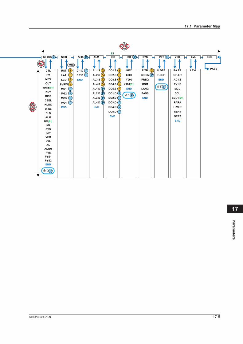
17-5IM 05P03D21-01EN
Parameters
17
IN
UNIT
RH
RL
SDP
SH
SL
BSL
RJC
ERJC
A.BS
A.FL
A.SR
A.LC
END
PSL
BPS
PRI
STP
DLN
ADR
RP.T
END
RTSRTHRTL
RET.HRET.LRET.AEND
DI1.D
DI2.D
END
PA.ER
OP.ER
AD1.E
PV1.E
MCU
DCU
ECU1(E1)
PARA
H.VER
SER1
SER2
END
U.DEF
F.DEF
END
R.TM
C.GRN
FREQ
QSM
LANG
PASS
END
KEY
X000
Y000
Y100(E1)
END
E1PV
P.UNI
P.DP
P.RH
P.RL
END
MPV
ALNO.
SMP
END
CTLPASS R485OUT DI.D VERINITSYSI/O
RST
LAT
LCD
PVRW
MG1
MG2
MG3
MG4
END
DI.SL
LEVL
LVL END
DO1.S
DO2.S
DO3.S
DO4.S
DO5.S
DO1.D
DO2.D
DO3.D
DO4.D
DO5.D
END
AL1.S
AL2.S
AL3.S
AL4.S
AL1.D
AL2.D
AL3.D
AL4.D
END
E1DOALM
+
END
PASSCTLPV
MPVOUT
R485(E1)
KEYDISPCSELKLOCDI.SLDI.DALM
DO(E1)
I/OSYSINITVERLVLAL
ALRMPVS
PYS1PYS2END
U.PV
COM.W
DATA
END
CS1
CS2
CS3
CS4
CS5
END
PCMDPCHPCLEV1EV2EV3EV4EV5EV6EV7EV8PV.DSP.D
STS.DSPDGUIDHOMEECOBRI
B.PVWB.PVRB.SPB.STSD.CYCOP.JPMLSDEND
Fn
END
MLOCKLOCCSELDISPKEY
P
P
PPPPPPP
P
PP
P
P
PPPPPP
P
S
S
S
P全て
PP
P
P
P
PP
S
SS
S
P
SS
S
SS
SS
P
S
P P
P
P
P
S
SS
SS
SS
SS
PPP
PP
SS
SS
PP
PPPP
P全て
P全て
PP
S全て
S全て
Displayedwhen
a passwordhas been set.
Setting parameters for the basic functions of the indicator
Press the keys for 3 seconds.
Operationdisplay
17.1 Parameter Map
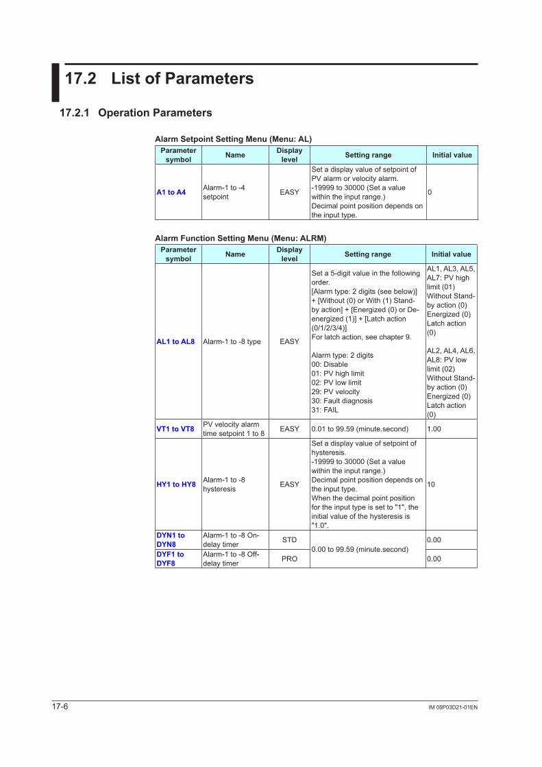
17-6 IM 05P03D21-01EN
17.2 List of Parameters
17.2.1 Operation Parameters
Alarm Setpoint Setting Menu (Menu: AL)Parameter
symbol Name Display level Setting range Initial value
A1 to A4 Alarm-1 to -4 setpoint EASY
Set a display value of setpoint of PValarmorvelocityalarm.-19999 to 30000 (Set a value within the input range.)Decimal point position depends on the input type.
0
Alarm Function Setting Menu (Menu: ALRM)Parameter
symbol Name Display level Setting range Initial value
AL1 to AL8 Alarm-1 to -8 type EASY
Set a 5-digit value in the following order.[Alarm type: 2 digits (see below)] + [Without (0) or With (1) Stand-by action] + [Energized (0) or De-energized (1)] + [Latch action (0/1/2/3/4)]For latch action, see chapter 9.
Alarm type: 2 digits00: Disable01:PVhighlimit02:PVlowlimit29:PVvelocity30: Fault diagnosis31: FAIL
AL1, AL3, AL5, AL7:PVhighlimit (01)Without Stand-by action (0)Energized (0)Latch action (0)
AL2, AL4, AL6, AL8:PVlowlimit (02)Without Stand-by action (0)Energized (0)Latch action (0)
VT1 to VT8 PVvelocityalarmtime setpoint 1 to 8 EASY 0.01 to 99.59 (minute.second) 1.00
HY1 to HY8 Alarm-1 to -8 hysteresis EASY
Set a display value of setpoint of hysteresis.-19999 to 30000 (Set a value within the input range.)Decimal point position depends on the input type.When the decimal point position for the input type is set to "1", the initial value of the hysteresis is "1.0".
10
DYN1 to DYN8
Alarm-1 to -8 On-delay timer STD
0.00 to 99.59 (minute.second)0.00
DYF1 to DYF8
Alarm-1 to -8 Off-delay timer PRO 0.00
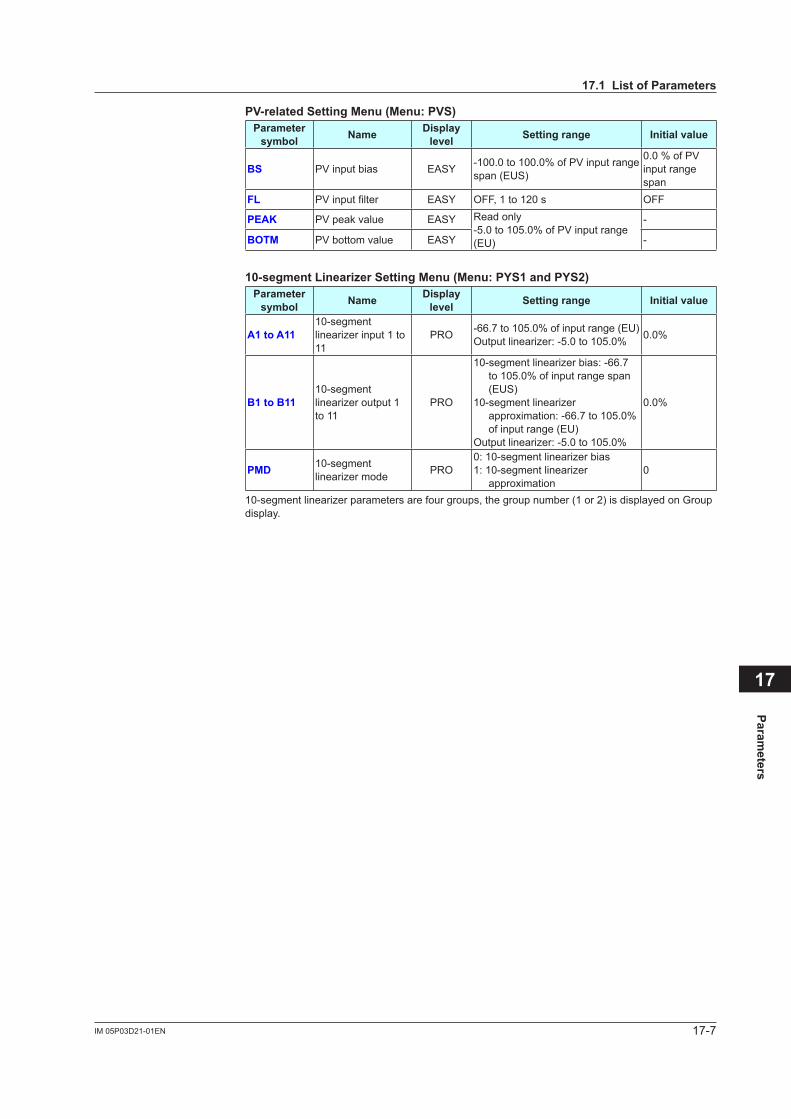
17-7IM 05P03D21-01EN
Parameters
17
17.1 List of Parameters
PV-related Setting Menu (Menu: PVS)Parameter
symbol Name Display level Setting range Initial value
BS PVinputbias EASY -100.0to100.0%ofPVinputrangespan (EUS)
0.0%ofPVinput range span
FL PVinputfilter EASY OFF, 1 to 120 s OFF
PEAK PVpeakvalue EASY Read only -5.0to105.0%ofPVinputrange(EU)
-
BOTM PVbottomvalue EASY -
10-segment Linearizer Setting Menu (Menu: PYS1 and PYS2)Parameter
symbol Name Display level Setting range Initial value
A1 to A1110-segment linearizer input 1 to 11
PRO -66.7to105.0%ofinputrange(EU)Outputlinearizer:-5.0to105.0% 0.0%
B1 to B1110-segment linearizer output 1 to 11
PRO
10-segment linearizer bias: -66.7 to105.0%ofinputrangespan(EUS)
10-segment linearizer approximation:-66.7to105.0%of input range (EU)
Outputlinearizer:-5.0to105.0%
0.0%
PMD 10-segment linearizer mode PRO
0: 10-segment linearizer bias1: 10-segment linearizer
approximation0
10-segment linearizer parameters are four groups, the group number (1 or 2) is displayed on Group display.
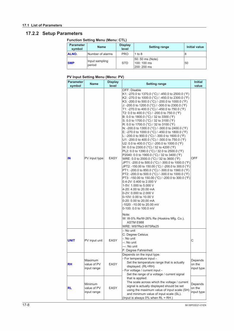
17-8 IM 05P03D21-01EN
17.2.2 Setup ParametersFunction Setting Menu (Menu: CTL)
Parameter symbol Name Display
level Setting range Initial value
ALNO. Number of alarms PRO 1 to 8 8
SMP Input sampling period STD
50: 50 ms (Note)100: 100 ms200: 200 ms
50
PV Input Setting Menu (Menu: PV)Parameter
symbol Name Display level Setting range Initial
value
IN PVinputtype EASY
OFF: DisableK1: -270.0 to 1370.0 (°C) / -450.0 to 2500.0 (°F)K2: -270.0 to 1000.0 (°C) / -450.0 to 2300.0 (°F)K3: -200.0 to 500.0 (°C) / -200.0 to 1000.0 (°F)J: -200.0 to 1200.0 (°C) / -300.0 to 2300.0 (°F)T1: -270.0 to 400.0 (°C) / -450.0 to 750.0 (°F)T2: 0.0 to 400.0 (°C) / -200.0 to 750.0 (°F)B: 0.0 to 1800.0 (°C) / 32 to 3300 (°F)S: 0.0 to 1700.0 (°C) / 32 to 3100 (°F)R: 0.0 to 1700.0 (°C) / 32 to 3100 (°F)N: -200.0 to 1300.0 (°C) / -300.0 to 2400.0 (°F)E: -270.0 to 1000.0 (°C) / -450.0 to 1800.0 (°F)L: -200.0 to 900.0 (°C) / -300.0 to 1600.0 (°F)U1: -200.0 to 400.0 (°C) / -300.0 to 750.0 (°F)U2: 0.0 to 400.0 (°C) / -200.0 to 1000.0 (°F)W: 0.0 to 2300.0 (°C) / 32 to 4200 (°F)PL2: 0.0 to 1390.0 (°C) / 32.0 to 2500.0 (°F)P2040: 0.0 to 1900.0 (°C) / 32 to 3400 (°F)WRE: 0.0 to 2000.0 (°C) / 32 to 3600 (°F)JPT1: -200.0 to 500.0 (°C) / -300.0 to 1000.0 (°F)JPT2: -150.00 to 150.00 (°C) / -200.0 to 300.0 (°F)PT1: -200.0 to 850.0 (°C) / -300.0 to 1560.0 (°F)PT2: -200.0 to 500.0 (°C) / -300.0 to 1000.0 (°F)PT3: -150.00 to 150.00 (°C) / -200.0 to 300.0 (°F)0.4-2V:0.400to2.000V1-5V:1.000to5.000V4-20: 4.00 to 20.00 mA0-2V:0.000to2.000V0-10V:0.00to10.00V0-20: 0.00 to 20.00 mA-1020:-10.00to20.00mV0-100:0.0to100.0mV
Note:W:W-5%Re/W-26%Re(HoskinsMfg.Co.),
ASTM E988WRE: W97Re3-W75Re25
OFF
UNIT PVinputunit EASY
-: No unitC: Degree Celsius-: No unit--: No unit---: No unitF: Degree Fahrenheit
C
RHMaximum valueofPVinput range
EASY
Depends on the input type.- For temperature input - Set the temperature range that is actually
displayed. (RL<RH)- For voltage / current input - Set the range of a voltage / current signal
that is applied. The scale across which the voltage / current
signal is actually displayed should be set using the maximum value of input scale (SH) and minimum value of input scale (SL).
(Inputisalways0%whenRL=RH.)
Depends on the input type
RLMinimum valueofPVinput range
EASYDepends on the input type
17.1 List of Parameters
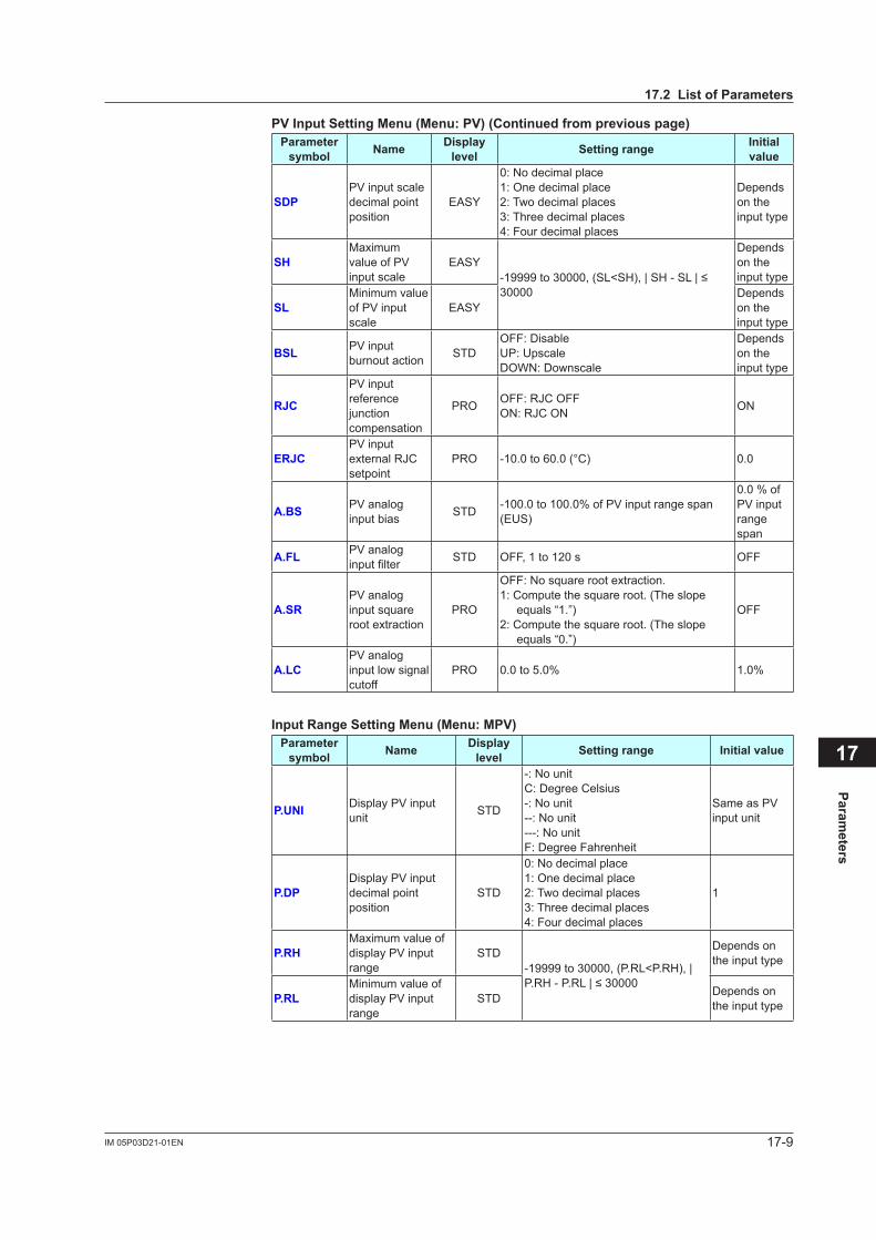
17-9IM 05P03D21-01EN
Parameters
17
PV Input Setting Menu (Menu: PV) (Continued from previous page)Parameter
symbol Name Display level Setting range Initial
value
SDPPVinputscaledecimal point position
EASY
0: No decimal place1: One decimal place2: Two decimal places3: Three decimal places4: Four decimal places
Depends on the input type
SHMaximum valueofPVinput scale
EASY-19999to30000,(SL<SH),|SH-SL|≤30000
Depends on the input type
SLMinimum value ofPVinputscale
EASYDepends on the input type
BSL PVinputburnout action STD
OFF: DisableUP: UpscaleDOWN: Downscale
Depends on the input type
RJC
PVinputreference junctioncompensation
PRO OFF: RJC OFFON: RJC ON ON
ERJCPVinputexternal RJC setpoint
PRO -10.0to60.0(°C) 0.0
A.BS PVanaloginput bias STD -100.0to100.0%ofPVinputrangespan
(EUS)
0.0%ofPVinputrange span
A.FL PVanaloginputfilter STD OFF, 1 to 120 s OFF
A.SRPVanaloginput square root extraction
PRO
OFF: No square root extraction.1: Compute the square root. (The slope
equals “1.”)2: Compute the square root. (The slope
equals “0.”)
OFF
A.LCPVanaloginput low signal cutoff
PRO 0.0to5.0% 1.0%
Input Range Setting Menu (Menu: MPV)Parameter
symbol Name Display level Setting range Initial value
P.UNI DisplayPVinputunit STD
-: No unitC: Degree Celsius-: No unit--: No unit---: No unitF: Degree Fahrenheit
SameasPVinput unit
P.DPDisplayPVinputdecimal point position
STD
0: No decimal place1: One decimal place2: Two decimal places3: Three decimal places4: Four decimal places
1
P.RHMaximum value of displayPVinputrange
STD-19999 to 30000, (P.RL<P.RH), | P.RH-P.RL|≤30000
Depends on the input type
P.RLMinimum value of displayPVinputrange
STD Depends on the input type
17.2 List of Parameters
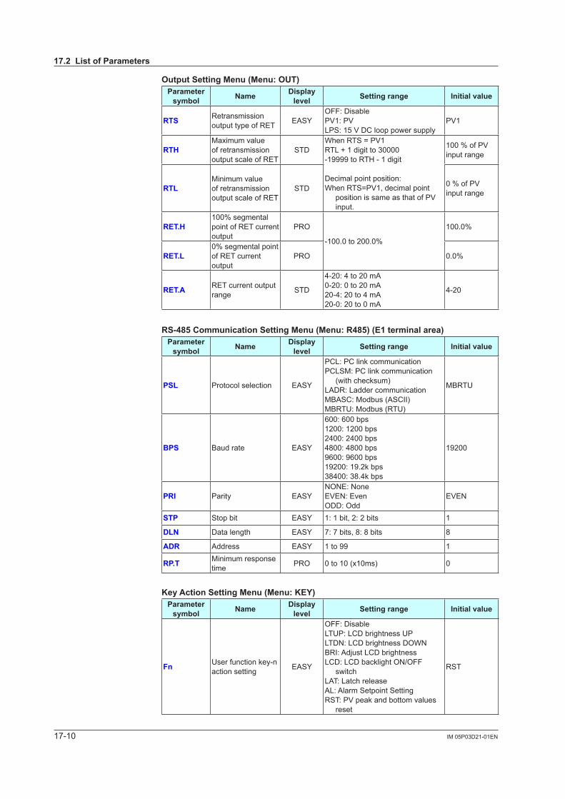
17-10 IM 05P03D21-01EN
Output Setting Menu (Menu: OUT)Parameter
symbol Name Display level Setting range Initial value
RTS Retransmission output type of RET EASY
OFF: DisablePV1:PVLPS:15VDClooppowersupply
PV1
RTHMaximum value of retransmission output scale of RET
STDWhenRTS=PV1RTL + 1 digit to 30000-19999 to RTH - 1 digit
Decimal point position:WhenRTS=PV1,decimalpoint
positionissameasthatofPVinput.
100%ofPVinput range
RTLMinimum value of retransmission output scale of RET
STD 0%ofPVinput range
RET.H100%segmentalpoint of RET current output
PRO
-100.0to200.0%
100.0%
RET.L0%segmentalpointof RET current output
PRO 0.0%
RET.A RET current output range STD
4-20: 4 to 20 mA0-20: 0 to 20 mA20-4: 20 to 4 mA20-0: 20 to 0 mA
4-20
RS-485 Communication Setting Menu (Menu: R485) (E1 terminal area)Parameter
symbol Name Display level Setting range Initial value
PSL Protocol selection EASY
PCL: PC link communicationPCLSM: PC link communication
(with checksum)LADR: Ladder communicationMBASC: Modbus (ASCII)MBRTU: Modbus (RTU)
MBRTU
BPS Baud rate EASY
600: 600 bps1200: 1200 bps2400: 2400 bps4800: 4800 bps9600: 9600 bps19200: 19.2k bps38400: 38.4k bps
19200
PRI Parity EASYNONE: NoneEVEN:EvenODD: Odd
EVEN
STP Stop bit EASY 1: 1 bit, 2: 2 bits 1
DLN Data length EASY 7: 7 bits, 8: 8 bits 8
ADR Address EASY 1 to 99 1
RP.T Minimum response time PRO 0 to 10 (x10ms) 0
Key Action Setting Menu (Menu: KEY)Parameter
symbol Name Display level Setting range Initial value
Fn User function key-n action setting EASY
OFF: DisableLTUP: LCD brightness UPLTDN: LCD brightness DOWNBRI:AdjustLCDbrightnessLCD: LCD backlight ON/OFF
switchLAT: Latch releaseAL: Alarm Setpoint SettingRST:PVpeakandbottomvalues
reset
RST
17.2 List of Parameters
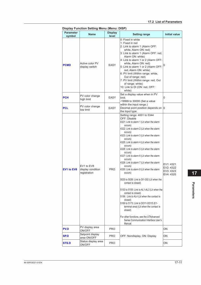
17-11IM 05P03D21-01EN
Parameters
17
Display Function Setting Menu (Menu: DISP)Parameter
symbol Name Display level Setting range Initial value
PCMD ActivecolorPVdisplay switch EASY
0: Fixed in white1: Fixed in red2: Link to alarm 1 (Alarm OFF:
white, Alarm ON: red)3: Link to alarm 1 (Alarm OFF: red,
Alarm ON: white)4: Link to alarm 1 or 2 (Alarm OFF:
white, Alarm ON: red)5: Link to alarm 1 or 2 (Alarm OFF:
red, Alarm ON: white)6:PVlimit(Withinrange:white,
Out of range: red)7:PVlimit(Withinrange:red,Out
of range: white)10: Link to DI (ON: red, OFF:
white)
0
PCH PVcolorchangehigh limit EASY
SetadisplayvaluewheninPVlimit.-19999 to 30000 (Set a value within the input range.)Decimal point position depends on the input type.
0
PCL PVcolorchangelow limit EASY 0
EV1 to EV8EV1toEV8display condition registration
PRO
Setting range: 4001 to 5344OFF: Disable4321: Link to alarm 1 (Lit when the alarm
occurs)4322: Link to alarm 2 (Lit when the alarm
occurs)4323: Link to alarm 3 (Lit when the alarm
occurs)4325: Link to alarm 4 (Lit when the alarm
occurs)4326: Link to alarm 5 (Lit when the alarm
occurs)4327: Link to alarm 6 (Lit when the alarm
occurs)4329: Link to alarm 7 (Lit when the alarm
occurs)4330: Link to alarm 8 (Lit when the alarm
occurs)
5025 to 5026: Link to DI1-DI2 (Lit when the contact is closed)
5153 to 5155: Link to AL1-AL3 (Lit when the contact is closed)
5156: Link to AL4 (Lit when the contact is closed)
5169 to 5173: Link to DO11-DO15 (E1-terminal area) (Lit when the contact is closed)
For other functions, see the UTAdvanced Series Communication Interface User’s Manual.
EV1:4321EV2:4322EV3:4323EV4:4325
PV.D PVdisplayareaON/OFF PRO
OFF: Nondisplay, ON: Display
ON
SP.D Setpoint display area ON/OFF PRO ON
STS.D Status display area ON/OFF PRO ON
17.2 List of Parameters
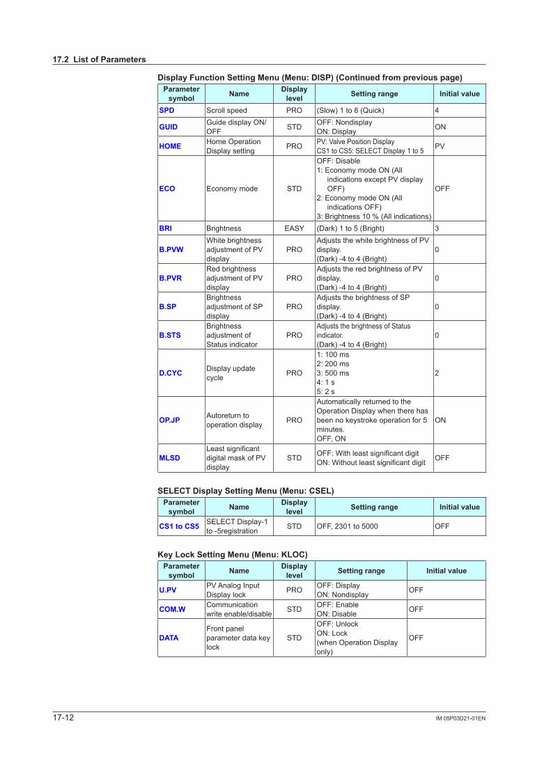
17-12 IM 05P03D21-01EN
Display Function Setting Menu (Menu: DISP) (Continued from previous page)Parameter
symbol Name Display level Setting range Initial value
SPD Scroll speed PRO (Slow) 1 to 8 (Quick) 4
GUID Guide display ON/OFF STD OFF: Nondisplay
ON: Display ON
HOME Home Operation Display setting PRO PV:ValvePositionDisplay
CS1 to CS5: SELECT Display 1 to 5 PV
ECO Economy mode STD
OFF: Disable1: Economy mode ON (All
indicationsexceptPVdisplayOFF)
2: Economy mode ON (All indications OFF)
3:Brightness10%(Allindications)
OFF
BRI Brightness EASY (Dark) 1 to 5 (Bright) 3
B.PVWWhite brightness adjustmentofPVdisplay
PROAdjuststhewhitebrightnessofPVdisplay.(Dark) -4 to 4 (Bright)
0
B.PVRRed brightness adjustmentofPVdisplay
PROAdjuststheredbrightnessofPVdisplay.(Dark) -4 to 4 (Bright)
0
B.SPBrightness adjustmentofSPdisplay
PROAdjuststhebrightnessofSPdisplay.(Dark) -4 to 4 (Bright)
0
B.STSBrightness adjustmentofStatus indicator
PROAdjuststhebrightnessofStatusindicator.(Dark) -4 to 4 (Bright)
0
D.CYC Display update cycle PRO
1: 100 ms2: 200 ms3: 500 ms4: 1 s5: 2 s
2
OP.JP Autoreturn to operation display PRO
Automatically returned to the Operation Display when there has been no keystroke operation for 5 minutes.OFF, ON
ON
MLSDLeastsignificantdigitalmaskofPVdisplay
STD OFF:WithleastsignificantdigitON:Withoutleastsignificantdigit OFF
SELECT Display Setting Menu (Menu: CSEL)Parameter
symbol Name Display level Setting range Initial value
CS1 to CS5 SELECT Display-1 to -5registration STD OFF, 2301 to 5000 OFF
Key Lock Setting Menu (Menu: KLOC)Parameter
symbol Name Display level Setting range Initial value
U.PV PVAnalogInputDisplay lock PRO OFF: Display
ON: Nondisplay OFF
COM.W Communication write enable/disable STD OFF: Enable
ON: Disable OFF
DATAFront panel parameter data key lock
STD
OFF: UnlockON: Lock(when Operation Display only)
OFF
17.2 List of Parameters
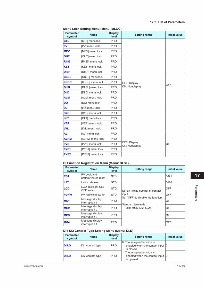
17-13IM 05P03D21-01EN
Parameters
17
Menu Lock Setting Menu (Menu: MLOC)Parameter
symbol Name Display level Setting range Initial value
CTL [CTL] menu lock PRO
OFF: DisplayON: Nondisplay OFF
PV [PV]menulock PRO
MPV [MPV]menulock PRO
OUT [OUT] menu lock PRO
R485 [R485] menu lock PRO
KEY [KEY] menu lock PRO
DISP [DISP] menu lock PRO
CSEL [CSEL] menu lock PRO
KLOC [KLOC] menu lock PRO
DI.SL [DI.SL] menu lock PRO
DI.D [DI.D] menu lock PRO
ALM [ALM] menu lock PRO
DO [DO] menu lock PRO
I/O [I/O] menu lock PRO
SYS [SYS] menu lock PRO
INIT [INIT] menu lock PRO
VER [VER]menulock PRO
LVL [LVL]menulock PRO
AL [AL] menu lock PRO
OFF: DisplayON: Nondisplay OFF
ALRM [ALRM] menu lock PRO
PVS [PVS]menulock PRO
PYS1 [PYS1] menu lock PRO
PYS2 [PYS2] menu lock PRO
DI Function Registration Menu (Menu: DI.SL)Parameter
symbol Name Display level Setting range Initial value
RST PVpeakandbottom values reset STD
Set an I relay number of contact input.Set “OFF” to disable the function.
Standard terminals DI1: 5025, DI2: 5026
5025
LAT Latch release STD 5026
LCD LCD backlight ON/OFF switch STD OFF
PVRW PVred/whiteswitch STD OFF
MG1 Message display interruption 1 PRO OFF
MG2 Message display interruption 2 PRO OFF
MG3 Message display interruption 3 PRO OFF
MG4 Message display interruption 4 PRO OFF
DI1-DI2 Contact Type Setting Menu (Menu: DI.D)Parameter
symbol Name Display level Setting range Initial value
DI1.D DI1 contact type PRO0: The assigned function is
enabled when the contact input is closed.
1: The assigned function is enabled when the contact input is opened.
0
DI2.D DI2 contact type PRO 0
17.2 List of Parameters
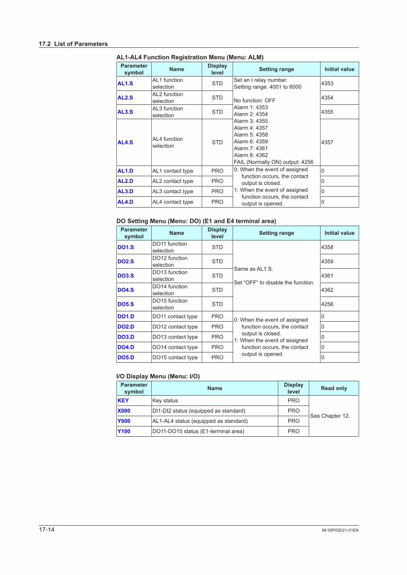
17-14 IM 05P03D21-01EN
AL1-AL4 Function Registration Menu (Menu: ALM)Parameter
symbol Name Display level Setting range Initial value
AL1.S AL1 function selection STD Set an I relay number.
Setting range: 4001 to 6000
No function: OFFAlarm 1: 4353Alarm 2: 4354Alarm 3: 4355Alarm 4: 4357Alarm 5: 4358Alarm 6: 4359Alarm 7: 4361Alarm 8: 4362FAIL (Normally ON) output: 4256
4353
AL2.S AL2 function selection STD 4354
AL3.S AL3 function selection STD 4355
AL4.S AL4 function selection STD 4357
AL1.D AL1 contact type PRO 0: When the event of assigned function occurs, the contact output is closed.
1: When the event of assigned function occurs, the contact output is opened.
0
AL2.D AL2 contact type PRO 0
AL3.D AL3 contact type PRO 0
AL4.D AL4 contact type PRO 0
DO Setting Menu (Menu: DO) (E1 and E4 terminal area)Parameter
symbol Name Display level Setting range Initial value
DO1.S DO11 function selection STD
Same as AL1.S.
Set “OFF” to disable the function.
4358
DO2.S DO12 function selection STD 4359
DO3.S DO13 function selection STD 4361
DO4.S DO14 function selection STD 4362
DO5.S DO15 function selection STD 4256
DO1.D DO11 contact type PRO 0: When the event of assigned function occurs, the contact output is closed.
1: When the event of assigned function occurs, the contact output is opened.
0
DO2.D DO12 contact type PRO 0
DO3.D DO13 contact type PRO 0
DO4.D DO14 contact type PRO 0
DO5.D DO15 contact type PRO 0
I/O Display Menu (Menu: I/O)Parameter
symbol Name Display level Read only
KEY Key status PRO
See Chapter 12.X000 DI1-DI2 status (equipped as standard) PRO
Y000 AL1-AL4 status (equipped as standard) PRO
Y100 DO11-DO15 status (E1-terminal area) PRO
17.2 List of Parameters
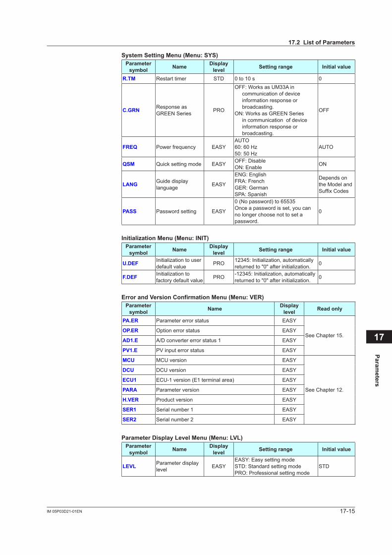
17-15IM 05P03D21-01EN
Parameters
17
System Setting Menu (Menu: SYS)Parameter
symbol Name Display level Setting range Initial value
R.TM Restart timer STD 0 to 10 s 0
C.GRN Response as GREEN Series PRO
OFF: Works as UM33A in communication of device information response or broadcasting.
ON: Works as GREEN Series in communication of device information response or broadcasting.
OFF
FREQ Power frequency EASYAUTO60: 60 Hz50: 50 Hz
AUTO
QSM Quick setting mode EASY OFF: DisableON: Enable ON
LANG Guide display language EASY
ENG: EnglishFRA: FrenchGER: GermanSPA: Spanish
Depends on the Model and SuffixCodes
PASS Password setting EASY
0 (No password) to 65535Once a password is set, you can no longer choose not to set a password.
0
Initialization Menu (Menu: INIT)Parameter
symbol Name Display level Setting range Initial value
U.DEF Initialization to user default value PRO 12345: Initialization, automatically
returned to "0" after initialization. 0
F.DEF Initialization to factory default value PRO -12345: Initialization, automatically
returned to "0" after initialization. 0
Error and Version Confirmation Menu (Menu: VER)Parameter
symbol Name Display level Read only
PA.ER Parameter error status EASY
See Chapter 15.OP.ER Option error status EASY
AD1.E A/D converter error status 1 EASY
PV1.E PVinputerrorstatus EASY
MCU MCU version EASY
See Chapter 12.
DCU DCU version EASY
ECU1 ECU-1 version (E1 terminal area) EASY
PARA Parameter version EASY
H.VER Product version EASY
SER1 Serial number 1 EASY
SER2 Serial number 2 EASY
Parameter Display Level Menu (Menu: LVL)Parameter
symbol Name Display level Setting range Initial value
LEVL Parameter display level EASY
EASY: Easy setting modeSTD: Standard setting modePRO: Professional setting mode
STD
17.2 List of Parameters

Blank Page
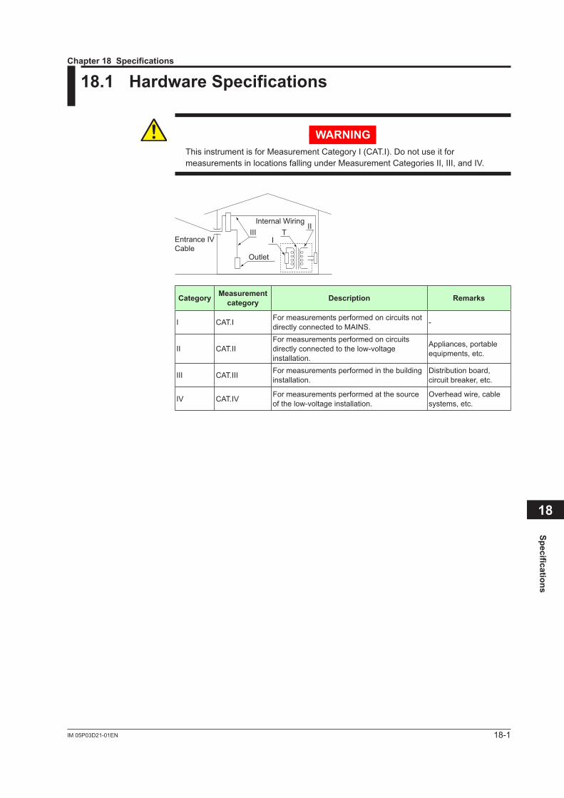
18-1IM 05P03D21-01EN
Specifications
18
18.1 Hardware Specifications
WARNINGThis instrument is for Measurement Category I (CAT.I). Do not use it for measurementsinlocationsfallingunderMeasurementCategoriesII,III,andIV.
Internal Wiring
Outlet
Entrance IVCable
III TI
II
Category Measurement category Description Remarks
I CAT.I For measurements performed on circuits not directly connected to MAINS. -
II CAT.IIFor measurements performed on circuits directly connected to the low-voltage installation.
Appliances, portable equipments, etc.
III CAT.III For measurements performed in the building installation.
Distribution board, circuit breaker, etc.
IV CAT.IV For measurements performed at the source of the low-voltage installation.
Overhead wire, cable systems, etc.
Chapter 18 Specifications
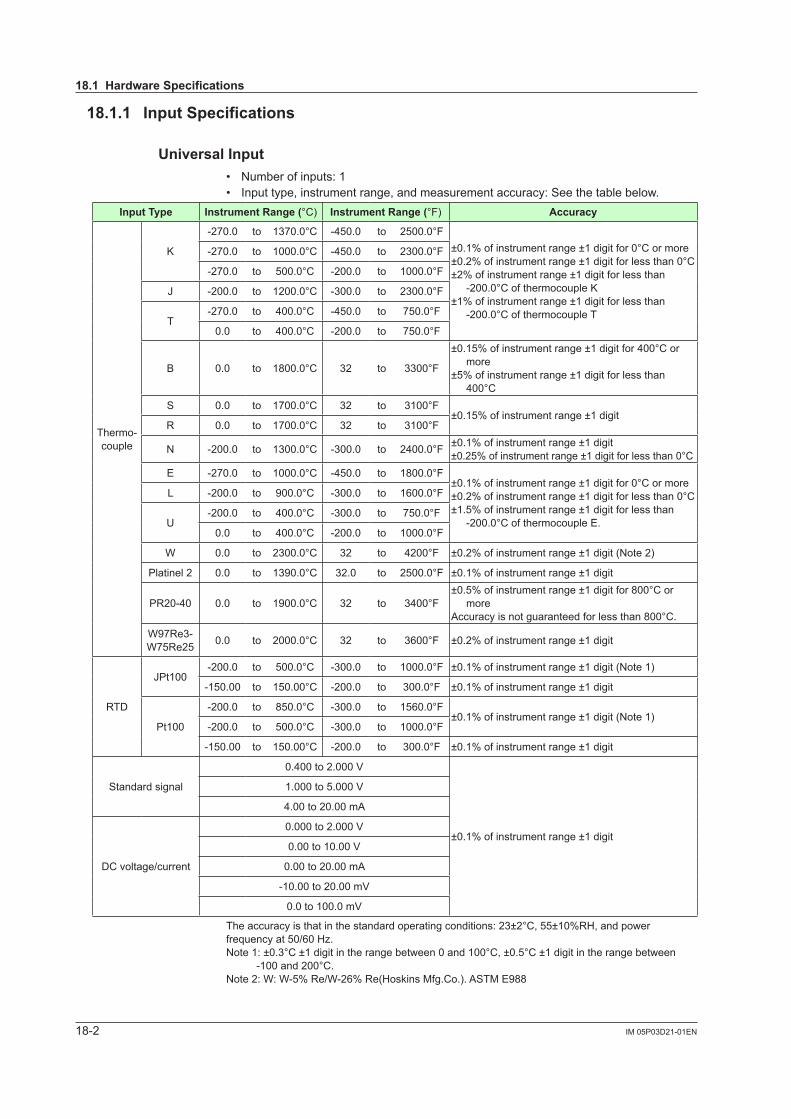
18-2 IM 05P03D21-01EN
18.1.1 Input Specifications
Universal Input• Number of inputs: 1• Input type, instrument range, and measurement accuracy: See the table below.
Input Type Instrument Range (°C) Instrument Range (°F) Accuracy
Thermo-couple
K
-270.0 to 1370.0°C -450.0 to 2500.0°F±0.1%ofinstrumentrange±1digitfor0°Cormore±0.2%ofinstrumentrange±1digitforlessthan0°C±2%ofinstrumentrange±1digitforlessthan
-200.0°CofthermocoupleK±1%ofinstrumentrange±1digitforlessthan
-200.0°CofthermocoupleT
-270.0 to 1000.0°C -450.0 to 2300.0°F
-270.0 to 500.0°C -200.0 to 1000.0°F
J -200.0 to 1200.0°C -300.0 to 2300.0°F
T-270.0 to 400.0°C -450.0 to 750.0°F
0.0 to 400.0°C -200.0 to 750.0°F
B 0.0 to 1800.0°C 32 to 3300°F
±0.15%ofinstrumentrange±1digitfor400°Cormore
±5%ofinstrumentrange±1digitforlessthan 400°C
S 0.0 to 1700.0°C 32 to 3100°F±0.15%ofinstrumentrange±1digit
R 0.0 to 1700.0°C 32 to 3100°F
N -200.0 to 1300.0°C -300.0 to 2400.0°F ±0.1%ofinstrumentrange±1digit±0.25%ofinstrumentrange±1digitforlessthan0°C
E -270.0 to 1000.0°C -450.0 to 1800.0°F±0.1%ofinstrumentrange±1digitfor0°Cormore±0.2%ofinstrumentrange±1digitforlessthan0°C±1.5%ofinstrumentrange±1digitforlessthan
-200.0°CofthermocoupleE.
L -200.0 to 900.0°C -300.0 to 1600.0°F
U-200.0 to 400.0°C -300.0 to 750.0°F
0.0 to 400.0°C -200.0 to 1000.0°F
W 0.0 to 2300.0°C 32 to 4200°F ±0.2%ofinstrumentrange±1digit(Note2)
Platinel 2 0.0 to 1390.0°C 32.0 to 2500.0°F ±0.1%ofinstrumentrange±1digit
PR20-40 0.0 to 1900.0°C 32 to 3400°F±0.5%ofinstrumentrange±1digitfor800°Cor
moreAccuracyisnotguaranteedforlessthan800°C.
W97Re3-W75Re25 0.0 to 2000.0°C 32 to 3600°F ±0.2%ofinstrumentrange±1digit
RTD
JPt100-200.0 to 500.0°C -300.0 to 1000.0°F ±0.1%ofinstrumentrange±1digit(Note1)
-150.00 to 150.00°C -200.0 to 300.0°F ±0.1%ofinstrumentrange±1digit
Pt100
-200.0 to 850.0°C -300.0 to 1560.0°F±0.1%ofinstrumentrange±1digit(Note1)
-200.0 to 500.0°C -300.0 to 1000.0°F
-150.00 to 150.00°C -200.0 to 300.0°F ±0.1%ofinstrumentrange±1digit
Standard signal
0.400 to 2.000V
±0.1%ofinstrumentrange±1digit
1.000 to 5.000V
4.00 to 20.00 mA
DC voltage/current
0.000 to 2.000V
0.00 to 10.00V
0.00 to 20.00 mA
-10.00 to 20.00mV
0.0 to 100.0mV
Theaccuracyisthatinthestandardoperatingconditions:23±2°C,55±10%RH,andpowerfrequency at 50/60 Hz.Note1:±0.3°C±1digitintherangebetween0and100°C,±0.5°C±1digitintherangebetween
-100and200°C.Note2:W:W-5%Re/W-26%Re(HoskinsMfg.Co.).ASTME988
18.1 Hardware Specifications
18-3IM 05P03D21-01EN
Specifications
18
• Input sampling period: Select from among 50, 100, and 200 ms• Burnout detection:
Functions at TC, RTD, and standard signal Upscale, downscale, and off can be specified. Forstandardsignal,burnoutisdeterminedtohaveoccurredifitis0.1Vor0.4mA
or less.• Input bias current: 0.05 µA (for TC or RTD)• Measurement current (RTD): About 0.16 mA• Input resistance:
TCormVinput:1MΩormore Vinput:About1MΩ mAinput:About250Ω
• Allowable signal source resistance: TCormVinput:250Ωorless Effectsofsignalsourceresistance:0.1µV/Ωorless DCvoltageinput:2kΩorless Effectsofsignalsourceresistance:About0.01%/100Ω
• Allowable wiring resistance: RTDinput:Max.150Ω/wire(Theconductorresistancebetweenthethreewires
shall be equal.) Wiringresistanceeffect:±0.1ºC/10Ω
• Allowable input voltage/current: TC,mV,mAorRTDinput:±10VDC Vinput:±20VDC mA input: ±40 mA
• Noiserejectionratio: Normal mode: 40 dB or more (50/60 Hz) Common mode: 120 dB or more (50/60 Hz) For100-240VAC,thepowerfrequencycanbesetmanually.Automaticdetection
is also available. For24VAC/DC,thepowerfrequencycanbesetmanually.
• Referencejunctioncompensationerror: ±1.0ºC (15 to 35ºC) ±1.5ºC (-10 to 15ºC, 35 to 50ºC)
• Applicable standards: JIS/IEC/DIN (ITS-90) for TC and RTD
18.1.2 Step Response Time SpecificationsWithin 500 ms (when the input sampling period is 50 ms or 100 ms)Within 1 s (when the input sampling period is 200 ms)(63%ofanalogoutputresponsetimewhenastepchangeof10to90%ofinputspanisapplied)
18.1.3 Relay Contact Output Specifications• Contact type and number of outputs:
Alarm-1 to -3 output: contact point 1a; 3 points (common is independent) Alarm-4 output: contact point 1c; 1 point
• Contact rating: Contactpoint1a(alarm-1to-3output):240VAC,1Aor30VDC,1A(resistance
load) Contact point 1c (alarm-4output):250VAC,3Aor30VDC,3A(resistanceload)
• Use: Alarm output, FAIL output, etc.Note: Cannot be used for a small load of 10 mA or less.
18.1 Hardware Specifications
18-4 IM 05P03D21-01EN
18.1.4 Retransmission Output Specifications• Numberofoutputs:Retransmissionoutput;1,sharedwith15VDClooppowersupply• Currentoutput:4to20mADCor0to20mADC/loadresistanceof600Ωorless• Currentoutputaccuracy:±0.1%ofspan(±5%ofspanfor1mAorless.)
Theaccuracyisthatinthestandardoperatingconditions:23±2°C,55±10%RH,andpower frequency at 50/60 Hz.
18.1.5 15 V DC Loop Power Supply Specifications(Shared with retransmission output)• Powersupply:14.5to18.0VDC• Maximum power supply: About 21 mA (with short-circuit current limiting circuit)
18.1.6 Contact Input Specifications• Number of inputs: 2 points• Input type: No-voltage contact input or transistor contact input• Inputcontactrating:12VDC,10mAormore
Use a contact of a minimum on-current of 1 mA or more • ON/OFF detection:
No-voltage contact input: Contactresistanceof1kΩorlessisdeterminedas“ON”andcontactresistance
of50kΩormoreas“OFF.” Transistor contact input:
Inputvoltageof2Vorlessisdeterminedas“ON”andleakagecurrentmustnotexceed 100 µA when “OFF.”
• Minimum status detection hold time: Input sampling period +50 ms• Use: Event input
18.1.7 Transistor Contact Output Specifications• Number of outputs: See the table of Model and Suffix Codes.• Output type: Open collector (SINK current)• Outputcontactrating:Max.24VDC,50mA• Output time resolution: Min. 50 ms• Use: Alarm output, FAIL output, etc.
18.1.8 24 V DC Loop Power Supply Specifications• Use: Power is supplied to a 2-wire transmitter.• Powersupply:21.6to28.0VDC• Rated current: 4 to 20 mA DC• Maximum power supply: About 30 mA (with short circuit current limiting circuit)
18.1 Hardware Specifications
18-5IM 05P03D21-01EN
Specifications
18
18.1.9 Safety and EMC Standards• Safety: Compliant with IEC/EN61010-1 (CE), approved by CAN/CSA C22.2
No.61010-1 (CSA), approved by UL61010-1. Installation category: CAT. II Pollution degree: 2 Measurement category: I (CAT. I) Ratedmeasurementinputvoltage:Max.10VDC Ratedtransientovervoltage:1500V(Note)Note: This is a reference safety standard value for Measurement Category I of IEC/EN/CSA/
UL61010-1. This value is not necessarily a guarantee of instrument performance.
• EMC Conformity standards: CE marking EN61326-1 Class A, Table 2 (For use in industrial locations) EN61326-2-3 EN 55011 Class A, Group1 EN 61000-3-2 Class A EN 61000-3-3 C-tick mark EN 55011 Class A, Group1Theinstrumentcontinuestooperateatameasurementaccuracyofwithin±20%oftherange during testing
18.1.10 Construction, Installation, and Wiring• Dust-proof and drip-proof: IP56 (for front panel)• Material:Polycarbonate(Flameretardancy:UL94V-0)• Case color: White (Light gray) or Black (Light charcoal gray)• Weight: 0.5 kg or less• External dimensions (mm): 96 (W) × 48 (H) × 65 (depth from the panel face)
(Depthexcepttheprojectionontherearpanel)• Installation: Direct panel mounting; mounting bracket, one each for left and right
mounting• Panel cutout dimensions (mm): 92+0.8/0 (W) × 45+0.6/0 (H)• Mounting attitude: Up to 30 degrees above the horizontal. No downward titling
allowed.• Wiring: M3 screw terminal with square washer (for signal wiring and power wiring)
19.1 Hardware Specifications
18-6 IM 05P03D21-01EN
18.1.11 Power Supply Specifications and Isolation • Power supply:
Ratedvoltage: 100–240VAC(+10%/-15%),50/60Hz 24VAC/DC(+10%/-15%)(for/DCoption)
• Powerconsumption:15VA(DC:7VA,AC:11VAif/DCoptionisspecified)• Data backup: Nonvolatile memory• Powerholduptime:20ms(for100VACdrive)• Withstanding voltage -Betweenprimaryterminalsandsecondaryterminals:2300VACfor1minute -Betweenprimaryterminals:1500VACfor1minute -Betweensecondaryterminals:500VACfor1minute
(Primary terminals: Power (*) and relay output terminals; Secondary terminals: Analog I/O signal terminals, contact input terminals, communication terminals, and functional grounding terminals.)
(*):Powerterminalsfor24VAC/DCmodelsarethesecondaryterminals.• Insulation resistance Betweenpowersupplyterminalsandagroundingterminal:20MΩormoreat500V
DC
• Isolation specifications
`
PV (universal ) input terminals
Alarm-4 relay (contact point c) output terminals
Alarm-1 relay (contact point a) output terminals
Alarm-2 relay (contact point a) output terminals
Alarm-3 relay (contact point a) output terminals
Contact input terminals (All)RS-485 communication terminals
24 V DC loop power supply terminals
Contact output (transistor) terminals
The circuits divided by lines are insulated multually.
Retransmission (analog) output terminals(not isolated between the analog output terminals)
Internalcircuits
Powersupply
18.1 Hardware Specifications

18-7IM 05P03D21-01EN
Specifications
18
18.1 Hardware Specifications
18.1.12 Environmental ConditionsNormal Operating Conditions
• Ambient temperature: -10 to 50ºC • Ambienthumidity:20to90%RH(nocondensationallowed)• Magnetic field: 400 A/m or less• Continuous vibration at 5 to 9 Hz: Half amplitude of 1.5 mm or less, 1oct/min for 90
minutes each in the three axis directions Continuous vibration at 9 to 150 Hz: 4.9 m/s2 or less, 1oct/min for 90 minutes each in
the three axis directions• Short-period vibration: 14.7 m/s2, 15 seconds or less• Shock: 98 m/s2 or less, 11 ms• Altitude: 2000 m or less above sea level• Warm-up time: 30 minutes or more after the power is turned on• Startup time: Within 10 seconds*: The LCD (a liquid crystal display) is used for a display portion of this product. The LCD has a characteristic that the display action becomes late at the low temperature.
Transportation and Storage Conditions• Temperature: -25 to 70ºC• Temperature change rate: 20ºC/h or less• Humidity:5to95%RH(nocondensationallowed)
Effects of Operating Conditions• Effect of ambient temperature:
VoltageorTCinput:±1µV/ºCor±0.01%ofF.S./ºC,whicheverislarger Currentinput:±0.01%ofF.S./ºC RTD input: ±0.05ºC/ºC (ambient temperature) or less Analogoutput:±0.02%ofF.S./ºCorless
• Effect of power supply voltage fluctuation Analoginput:±0.05%ofF.S.orless Analogoutput:±0.05%ofF.S.orless (Each within rated voltage range)

Blank Page
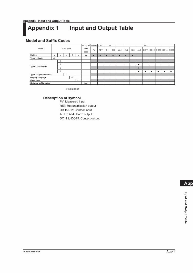
App-1IM 05P03D21-01EN
Input and Output Table
App
Appendix Input and Output Table
Appendix 1 Input and Output Table
Model and Suffix Codes
Model Suffix code
Optional
suffix
code
INPUT OUT DI DO
PV RET DI1 DI2 AL1 AL2 AL3 AL4 DO11 DO12 DO13 DO14 DO15
UM33A -x x x -0 x /xx Type 1: Basic -0
Type 2: Functions
01 2 3
Type 3: Open networks 0Display language -0Case color xOptional suffix codes /xx
: Equipped
Description of symbolPV:MeasuredinputRET: Retransmission outputDI1 to DI2: Contact inputAL1 to AL4: Alarm outputDO11 to DO15: Contact output

Blank Page
i
Revision Information Title : UM33A Digital Indicator with Alarms User’s Manual Manual No. : IM 05P03D21-01EN
Aug. 2010/1st EditionNewly published
Jan. 2011/2nd EditionUL approved and error correction
n Written by Yokogawa Electric Corporation n Published by Yokogawa Electric Corporation 2-9-32 Nakacho, Musashino-shi, Tokyo 180-8750, JAPAN

Blank Page
YOKOGAWA ELECTRIC CORPORATIONHeadquarters2-9-32, Nakacho, Musashino-shi, Tokyo, 180-8750 JAPAN
Branch Sales OfficesNagoya, Osaka, Hiroshima, Fukuoka, Sendai, Ichihara, Toyota, Kanazawa, and Kitakyusyu.
YOKOGAWA CORPORATION OF AMERICA2 Dart Road, Newnan, Georgia 30265-1094, U.S.A.Phone : 1-800-888-6400Fax : 1-770-254-0928
YOKOGAWA EUROPE B. V.Euroweg 2, 3825 HD Amersfoort, THE NETHERLANDSPhone : 31-88-4641000 Fax : 31-88-4641111
Branch Sales Offices / Wien (Austria), Zaventem (Belgium),Ratingen (Germany), Madrid (Spain), Runcorn (United Kingdom), Milano (Italy), Velizy-Villacoublay (France), Budapest (Hungary), Stockholm (Sweden), Sola (Norway), Warszawa (Poland), Vila Nova de Gaia (Portugal), Bucharest (Romania), Dublin (Ireland)
YOKOGAWA AMERICA DO SUL LTDA.Praca Acapulco, 31 - Santo Amaro. Sao Paulo/SP - BRAZILPhone : 55-11-5681-2400 Fax : 55-11-5681-4434
YOKOGAWA ENGINEERING ASIA PTE. LTD.5 Bedok South Road, 469270 SINGAPOREPhone : 65-6241-9933 Fax : 65-6241-2606
YOKOGAWA ELECTRIC KOREA CO., LTD.14-1, Yangpyongdong-4Ga, Youngdeungpo-Gu, Seoul, 150-866 KOREAPhone : 82-2-2628-6000 Fax : 82-2-2628-6400
YOKOGAWA AUSTRALIA PTY. LTD.Tower A, 112-118 Talavera Road, Macquarie Park,N.S.W.2113, AUSTRALIAPhone : 61-2-8870-1100 Fax : 61-2-8870-1111
YOKOGAWA INDIA LTD.Plot No.96 Electronic City Complex, Hosur Road, Bangalore 560100, INDIAPhone : 91-80-4158-6000 Fax : 91-80-2852-1442
YOKOGAWA CHINA CO., LTD.3F TowerD Cartelo Crocodile BuildingNo.568 West Tianshan Road, Shanghai 200335, CHINAPhone : 86-21-62396262 Fax : 86-21-62387866
Aug. '10
Printed in Korea