
USERS MANUAL - ads-img.co.jp€¦ · Users Manual – eco424, eco618, eco414, eco204,eco428,...
95
USERS MANUAL SVCam-ECO Line, eco618, eco424, eco414, eco415, eco204, eco445, eco267, eco285, eco274 and eco655 Gigabit Ethernet Cameras Digital Gigabit Ethernet Area-Scan Cameras Version 2.0 Last Update 21.01.2011
Transcript of USERS MANUAL - ads-img.co.jp€¦ · Users Manual – eco424, eco618, eco414, eco204,eco428,...

USERS MANUAL
SVCam-ECO Line, eco618, eco424, eco414,
eco415, eco204, eco445, eco267, eco285,
eco274 and eco655
Gigabit Ethernet Cameras
Digital Gigabit Ethernet Area-Scan Cameras
Version 2.0Last Update 21.01.2011

Users Manual – eco424, eco618, eco414, eco204,eco428, eco415, eco267,eco285, eco274 + eco655 p. 2
Contact:
SVS-VISTEK GmbH
Mühlbachstraße 2082229 Seefeld/Obb.Germany
Tel. +49-(0)8152-99 85-0www.svs-vistek.com
Service contact:E-Mail: [email protected]

Users Manual – eco424, eco414, eco 415, eco204, eco445, eco267, eco285, eco247 + eco655 p. 3
Content
1 INTRODUCTION ........................................................................................................................6
2 PINOUT AND INSTALLATION................................................................................................7
2.1 UNPACKING ....................................................................................................................................................... 72.2 POWER SUPPLY .................................................................................................................................................. 72.3 CONNECTORS ..................................................................................................................................................... 8
2.3.1 One common signal connector for:............................................................................................................... 8HR10A-10P-12PB (MATING CONNECTOR HR10A-10R-12S)......................................................................................... 8
2.3.2 “Ethernet” Connector .................................................................................................................................. 82.4 INSTALLATION/GETTING STARTED: RECOMMENDED PC.................................................................................... 82.5 HARDWARE...................................................................................................................................................... 102.6 AVAILABLE OPERATION MODES ....................................................................................................................... 10
2.6.1 General ....................................................................................................................................................... 102.6.2 Operation Modes ........................................................................................................................................ 11
2.7 LED SIGNALS SVCAM-ECO ........................................................................................................................... 11CAMERA STATUS ........................................................................................................................................................... 11BLINK CODES ................................................................................................................................................................ 11
3 SOFTWARE...............................................................................................................................12
3.1 SVCAPTURE/GIGE VISION CAMERA VIEWER .................................................................................................. 123.2 ADJUSTING TCP/IP RESPECTIVE NETWORK SETTINGS..................................................................................... 13
3.2.1 Network address assignment....................................................................................................................... 143.2.2 Persistent Network address assignment...................................................................................................... 153.2.3 Using jumbo frames .................................................................................................................................... 163.2.4 Performance considerations ....................................................................................................................... 163.2.5 Multicast ..................................................................................................................................................... 17
4 WINDOWS X64 SUPPORT ......................................................................................................18
5 CAMERA SETTINGS DIALOG ...............................................................................................19
5.1.1 Camera ....................................................................................................................................................... 215.1.2 Network....................................................................................................................................................... 215.1.3 Acquisition .................................................................................................................................................. 21
5.2 IMAGE .............................................................................................................................................................. 225.3 GAIN ................................................................................................................................................................ 235.4 OFFSET............................................................................................................................................................. 235.5 AUTOGAIN/AUTOEXPOSURE ........................................................................................................................... 23
6 ASSIGNING IO LINES .............................................................................................................24
6.1 ADJUSTING AN AOI (AREA OF INTEREST)......................................................................................................... 266.2 STROBE ............................................................................................................................................................ 266.3 PERSISTENCE ................................................................................................................................................... 26
7 SAVING IMAGES TO DISK ....................................................................................................27
8 DISPLAYING A CAMERA’S XML FILE ...............................................................................28
9 DISPLAYING A CAMERA’S FEATURE LIST ......................................................................29
10 OTHER MENU ITEMS..........................................................................................................29
11 CONTEXT MENU .................................................................................................................30
11.1 FILTER DRIVER ................................................................................................................................................ 3111.2 FIRMWARE UPDATE.......................................................................................................................................... 32
12 TECHNICAL DATA..............................................................................................................33
12.1 CCD USED/COSMETIC ISSUES:.......................................................................................................................... 3312.2 SIGNAL CONDITIONING .................................................................................................................................... 3312.3 OPTICAL AND MECHANICAL ISSUES.................................................................................................................. 33HR10A-10P-12PB (MATING CONNECTOR HR10A-10R-12S)....................................................................................... 35

Users Manual – eco424, eco414, eco 415, eco204, eco445, eco267, eco285, eco247 + eco655 p. 4
OPTION ......................................................................................................................................................................... 35BASIC ELECTRO-OPTIC SPECIFICATIONS OF CAMERAS .................................................................................................. 35BASIC ELECTRO-OPTIC SPECIFICATIONS OF CAMERAS .................................................................................................. 3612.4 ENVIRONMENTAL ISSUES ................................................................................................................................. 4112.5 SPECTRAL RESPONSE CURVES .......................................................................................................................... 4212.6 COMMENTS ON CAMERA TEMPERATURE .......................................................................................................... 4312.7 COMMENTS ON COLOR VERSION ..................................................................................................................... 43
13 WARRANTY TERMS ...........................................................................................................44
13.1 STANDARD PRODUCTS WARRANTY AND ADJUSTMENT ..................................................................................... 4413.2 DEVELOPMENT PRODUCT WARRANTY............................................................................................................. 44
14 APPENDIX A – TROUBLESHOOTING ..............................................................................46
14.1 GET CAMERA DIAGNOSTICS ............................................................................................................................. 46
15 TROUBLESHOOTING REQUEST LIST V1.3 ....................................................................49
16 APPENDIX B – BASIC TIMING FOR DIFFERENT OPERATION MODES....................50
16.1 FREE RUNNING ................................................................................................................................................ 5016.2 EXTERNAL TRIGGER AND PULSEWIDTH OF TRIGGER ....................................................................................... 5016.3 EXTERNAL AND SOFTWARE TRIGGER AND INTERNAL EXPOSURE TIME SETTING............................................... 50
17 APPENDIX C: SDK DESCRIPTION FOR CAMERA CONTROL .....................................51
17.1 OVERVIEW ....................................................................................................................................................... 5217.2 PREREQUISITES .............................................................................................................................................. 5217.3 SVGIGE SDK COMPONENTS.......................................................................................................................... 5217.4 DEVELOPMENT ENVIRONMENTS...................................................................................................................... 5317.5 WINDOWS X64 SUPPORT ................................................................................................................................ 5317.6 DOCUMENTATION ............................................................................................................................................ 5417.7 SYSTEM ARCHITECTURE ................................................................................................................................. 5417.8 FUNCTION GROUPS ......................................................................................................................................... 5517.9 DETAILED FUNCTION LISTING .......................................................................................................................... 5617.10 GENICAM INTERFACE ................................................................................................................................. 6117.11 BEST PROGRAMMING PRACTICES ............................................................................................................... 65
17.11.1 Connecting to the camera container ..................................................................................................... 6517.11.2 Connecting to a camera......................................................................................................................... 6517.11.3 Identifying a camera.............................................................................................................................. 6617.11.4 Determining maximal packet size ......................................................................................................... 6617.11.5 Opening a streaming channel ............................................................................................................... 6717.11.6 Receiving images in a callback function............................................................................................... 6717.11.7 Processing image data ........................................................................................................................... 6817.11.8 Decoding 12-bit images ......................................................................................................................... 6817.11.9 Adjusting tap balance automatically ..................................................................................................... 6917.11.10 Distributing image streams by multicast .......................................................................................... 7017.11.11 Receiving messages asynchronously ................................................................................................ 72
17.12 ADJUSTING IO CONFIGURATION .................................................................................................................. 7217.13 RS232 COMMUNICATION ............................................................................................................................. 74 APPLYING A LUT ................................................................................................................................................. 75 SVGIGE FILTERDRIVER INSTALLATION/DE-INSTALLATION ................................................................................. 76
18 APPENDIX D.........................................................................................................................77
AUTOMATED SVGIGE FILTERDRIVER INSTALLATION................................................77
AUTOMATED SVGIGE FILTERDRIVER DE-INSTALLATION .........................................78
MANUAL SVGIGE FILTERDRIVER INSTALLATION...............................................................80
18.1 INSTALLATION INSTRUCTION FOR FILTER DRIVER INSTALLATION ................................................................... 80
19 APPENDIX E .........................................................................................................................86
19.1 PC AND OS REQUIREMENTS ............................................................................................................................ 8619.2 FIREWALL CONSIDERATIONS ............................................................................................................................ 86

Users Manual – eco424, eco414, eco 415, eco204, eco445, eco267, eco285, eco247 + eco655 p. 5
20 APPENDIX F..........................................................................................................................88
20.1 FIRMWARE-UPDATE WITH “GIGE UPDATE TOOL.EXE“ PROGRAM ................................................................... 88
21 APPENDIX G.........................................................................................................................90
BASIC CIRCUITS FOR HARDWARE INTERFACING ................................................................90
FOR STROBE USE “OUT1”.........................................................................................................90
TTL INPUT CIRCUIT/ OUTPUT ( I.E STROBE ).........................................................................90
22 APPENDIX H SAFETY INSTARUCTIONS .......................................................................91
22.1 DEFINITION OF MARKINGS ............................................................................................................................... 9122.2 RESTRICTED FOR USE ...................................................................................................................................... 9422.3 CASES FOR INDEMINITY (LIMITED WARRANTY) .............................................................................................. 94

Users Manual – eco424, eco414, eco 415, eco204, eco445, eco267, eco285, eco247 + eco655 p. 6
1 Introduction
Thank you for purchasing a SVS-VISTEK product. SVS-VISTEK stands forreliable competence and customer oriented solutions in the field of professionalmachine vision systems. We believe that we are more than just a trade partnerof machine vision components and we believe in sharing our years ofdevelopment expertise with our customers. We offer single source solutionsand are a one-stop shopping center for all questions concerning professionalmachine vision. As a consequence, our insistence on the highest quality hasresulted in many companies worldwide that use our products and services withgreat success and satisfaction. Customers at home and abroad trust and relyon our know-how and experience.The following types are covered in this manual:
eco424 1/3” CCD, 640 x480 pixel, 12 Bit gray level resolution, ca. 124 fps;monochrome and color version
eco 414 1/2” CCD, 640 x 480 pixel, 12 Bit gray level resolution, ca. 125 fps;monochrome and color version
eco 415 1/2” CCD, 782 x 494 pixel, 12 Bit gray level resolution, ca. 86 fps;monochrome and color version
eco 618 1/4” CCD, 640 x 480 pixel, 12 Bit gray level resolution, ca. 160 fps; forIR applications
eco204 1/3”lCCD, 1024 x 768 pixel, 12 Bit gray level resolution, ca. 47 fps;monochrome and color version
eco445 1/3” CCD, 1280 x 960 pixel, 12 Bit gray level resolution, ca. 30fps;monochrome and color version
eco267 1/2” CCD, 1360 x 1024 pixel, 12 Bit gray level resolution, ca. 25 fps;monochrome and color version
svs285 2/3” CCD, 1360 x 1024 Pixel, 10/12 Bit gray level resolution, approx.34 frames/sec, monochrome and color version
eco274 1/2” CCD, 1600 x 1200 pixel, 12 Bit gray level resolution, ca. 26 fps;monochrome and color version .
svs655 2/3” CCD, 2456 x 2048 Pixel, 12 Bit gray level resolution, approx. 10frames/sec, monochrome and color version
For standard applications only 8 Bit are transmitted due to data load.For more information on the color versions, please see chapter 12.6.
If you need modifications, we will be glad to offer you a custom camerasuitable to your application.

Users Manual – eco424, eco414, eco 415, eco204, eco445, eco267, eco285, eco247 + eco655 p. 7
2 Pinout and Installation
Warning:The CCD camera is built with CMOS-LSI circuits. All internal electronics inthe camera are sensitive to high voltage or electrostatic discharge. Thecamera can be destroyed if carelessly handled, so extreme care shouldbe taken during set up and operation.
Do not expose the sensor to a direct laser beam as this could damage thesensor! See Safety Instructions at Appendix H. Warranty will be void ifnot followed.
2.1 Unpacking
Camera Power supply (if ordered/option) Mating connector User Manual Disk with SDK including “Filter Driver”, API and GUI “SVCapture” (for
GigE camera) program. Also a Firmware update tool.
XML File according to GenIcam standard released by AIA
committee.
2.2 Power supply
Current consumption:= 300 mA (typical)
Peak current on “Power on” up to 500 mA!Current consumption increases rapidly when “partial scan” feature isused!

Users Manual – eco424, eco414, eco 415, eco204, eco445, eco267, eco285, eco247 + eco655 p. 8
2.3 Connectors
2.3.1 One common signal connector for:
Trigger and TTL input to trigger camera General purpose I/Os UART communication Strobe Output (e.g. light ) Power
HR10A-10R-12PB (mating connector HR10A-10P-12S)
1 VIN- (GND)2 VIN+ (10 to 25DC)3 RXD data to camera (RS232 Level)4 TXD data from camera (RS232 Level)5 IN1 (0- 24 V) digital6 IN2 ( 0- 24 V) digital7 OUT1 (open drain max 24 V, 0.3 A) digital8 OUT2 (open drain max 24 V, 0.3 A) digital9 IN3+ (RS422 Level)10 IN3- (RS422 Level)11 OUT3 + (RS422 Level)12 OUT3- (RS422 Level)
See outline in chapter 12.3
2.3.2 “Ethernet” Connector
RJ 45 “Western” Connector complies with Autosensing 100 T Ethernetand Gigabit specification. Features Auto MDIX.
1 LED for status indication
2.4 Installation/Getting started: Recommended PC
It is recommended to use a PC with a Pentium P4 processor at 2,4 GHz orhigher. The camera is working also on lower frequencies but it might notdeliver the full frame rate in those cases.
If the camera is connected to the PC directly without using a network switch, afixed IP-Address and Subnet-Mask should be configured in the PC’sTCP/IP settings unless it is done by DHCP:
See: Start -> Settings -> Network connections -> LAN-connection ->Properties -> TCP/IP
A Gigabit Ethernet network adapter is needed (100 MBit adapters would alsowork, but with reduced frame rates). If your PC does not have a Gigabitinterface card purchase a card using an original INTEL (TM) Chip set.

Users Manual – eco424, eco414, eco 415, eco204, eco445, eco267, eco285, eco247 + eco655 p. 9
Currently PCI(e) bus cards with 82541 chip set version have been tested successfully.Currently we can recommend Intel pro 1000 PT,GT or MT. Recently problems with the “CT”version have been reported.
DO NOT USE INTEL PRO 1000 CT !!
If you do not follow this, a significantly reduced data transmission rateis observed. Also the loss of data can appear.

Users Manual – eco424, eco414, eco 415, eco204, eco445, eco267, eco285, eco247 + eco655 p. 10
2.5 Hardware
Install camera in the desired location. You can use the ¼’’ tripotadapter or use the 4 M3 holes in the adapter of the camera.
Connect the power supply. If you have ordered a P/S connect it to thecamera. If you use your own power supply ( e.g. 10 -25 V DC) makesure you connect it to Pin1(GND) and Pin 2 ( e.g. +12 -24 V).
If you – by mistake – supply line with GND pin the camera can bedamaged! If power supply was ordered, do not modify it.
Connect an Ethernet cable to your PC or a network switch like you would buildup a PC Network. Please note that cable length should not exceed 100 m fortheses camera (Cat 5E version). In doubt consult your local distributor.
Wait 15 seconds until the green LED at the RJ45 connector of the Camerablinks sometimes.
Then start “SVCapture.exe”.
2.6 Available operation modes
2.6.1 General
All modes are set by the interface which connects via Ethernet standardcable.
Minimum CAT 5E quality is required.
The default factory setting is Free Running/ Fixed frequency using theinternal logic for exposure control. You can also trigger the camera by hardwareand by PC (software trigger).
The color version will come on request with free software algorithm which willallow processing of the color image inside the PC or the camera. This must tobe done in order to interpolate the colors for each pixel. Please note that noresponsibility can be taken for the algorithm. It might be necessary to changethe algorithm according to the application.
See chapter 12.6

Users Manual – eco424, eco414, eco 415, eco204, eco445, eco267, eco285, eco247 + eco655 p. 11
2.6.2 Operation Modes
Free Running
Triggered, external exposure controlIf you want to trigger the camera and determine the exposure time bythe pulse width of Exsync, choose this mode. Then apply a trigger signalat the appropriate pins e.g. on pins of Phoenix connector (see 2.3.1).With the starting edge of the pulse the camera will start exposure time.The exposure time ends with next upcoming edge of Exsync. Pleasecheck the timing diagram in the appendix of this manual.
External triggered, internal camera exposure controlIf you want to trigger the camera and use the convenient exposure timecontrol of the micro controller then use this mode. You still can use theSVCapture GUI for setting exposure time (see “Exposure time”-fieldbelow). However you need to use the Exsync signal in order to triggerthe camera (see “Trigger”-buttons below).
External triggered via Software trigger with internal exposurecontrol
If you want to trigger the camera with a software trigger and use theSVCapture exposure time control of camera logic then use this mode.
2.7 LED Signals SVCam-ECO
Camera status
Signals: No connection with network cable (yellow slow) Allotment of the network address (yellow quick) Network address allotted (yellow) Connected with application (green) Streaming channel available (green slow) Acquisition enabled (green quick) Problem with initialization (red slow) Overheating (red quick)
Optional instead of “acquisition enabled”: Waiting for trigger (blue) Exposure active (cyan) Readout/FVAL (violet)
Blink codes
On Slow (approx. 1 Hz) Quickl (approx. 8 Hz)

Users Manual – eco424, eco414, eco 415, eco204, eco445, eco267, eco285, eco247 + eco655 p. 12
3 Software
3.1 SVCapture/GigE Vision Camera Viewer
Overview
You can use the SVCapture without the “Filter Driver” but if you want to lowerthe CPU load when grabbing images make sure it is installed.
You will observe a loss of frames if you do not use the driver.
If you have installed the camera and connected the power, you can install thedriver and the GUI to do the first test. Copy the “SVCapture.exe” to your diskdrive, double click on the SVCapture icon and a window will open.
The software SVCapture displays images sent from SVS-GigE-Cameras viaGigabit Ethernet to your PC (with Windows XP) and allows adjusting basiccamera settings.
Users Manual – eco424, eco414, eco 415, eco204, eco445, eco267, eco285, eco247 + eco655 p. 13
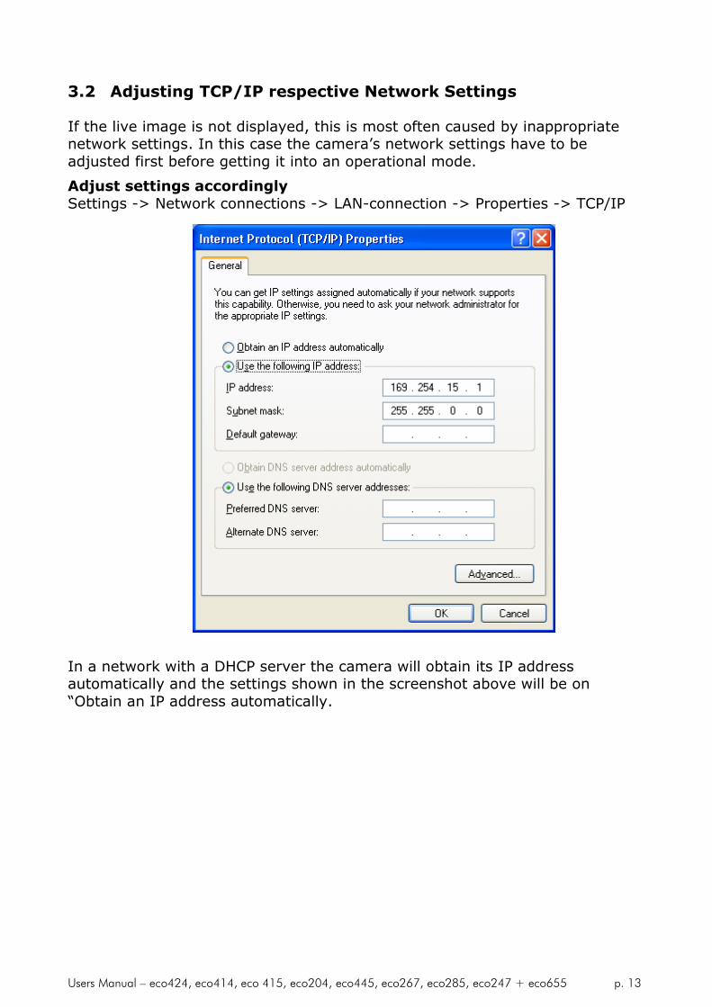
3.2 Adjusting TCP/IP respective Network Settings
If the live image is not displayed, this is most often caused by inappropriatenetwork settings. In this case the camera’s network settings have to beadjusted first before getting it into an operational mode.
Adjust settings accordinglySettings -> Network connections -> LAN-connection -> Properties -> TCP/IP
In a network with a DHCP server the camera will obtain its IP addressautomatically and the settings shown in the screenshot above will be on“Obtain an IP address automatically.

Users Manual – eco424, eco414, eco 415, eco204, eco445, eco267, eco285, eco247 + eco655 p. 14
3.2.1 Network address assignment
The main components of a network address are the IP (Internet Protocol)address and the network mask. The usually applied network mask“255.255.255.0” for small networks up to 254 PCs represents a 32-bit long bitmask where the first 24 bits are set to 1 and the last 8 bits are set to 0. Thisnetwork mask instructs the network hardware to let those devices exchangeinformation with each other where the first 24 bits of the IP addresses matchfor all devices.Thus the variable range of addresses is made from all possible combinations ofthe last 8 bits for which the network mask is set to 0. Exceptions are the firstaddress 0 and the last address 255 which have special meanings for networkmanagement functions. All other 254 combinations are usually free forassigning them to network devices.For a peer-to-peer connection of a GigE camera to a PC a network addressassignment based on LLA (Local Link Address) is recommended. This involvesa network mask “255.255.0.0” as well as a fixed first part “169.254.xxx.xxx”of the network address range. A GigE camera will fall back to LLA soon afterrecognizing that no DHCP server is available and that no fixed network addresswas assigned to the camera.In case a camera can not be reached by the SVCapture application a dialog willappear that allows for adjusting a camera’s network parameters. The simplestway is to click on “Automatic” which will provide to a search for a free IPaddress and to assigning it to the camera given that the interface IP could bedetermined properly.
That dialog can also be brought up when right clicking on an entry in thediscover dialog and subsequently selecting “Force IP address” in the contextmenu. However, when adjusting the PC network settings to LLA the cameramust not get assigned a fixed network addressNOTE: The network settings performed in the “Force IP address”dialog are only valid until the next shutdown and restart of a camera.For permanently changing a camera’s network settings the “Networksettings” dialog can be used instead. That dialog can also be opened inthe context menu which is displayed when right-clicking on an entry inthe discover dialog.
Users Manual – eco424, eco414, eco 415, eco204, eco445, eco267, eco285, eco247 + eco655 p. 15
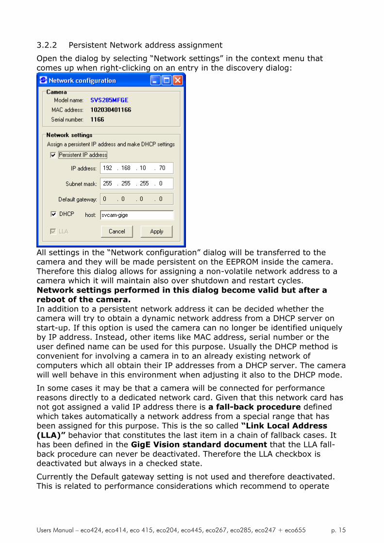
3.2.2 Persistent Network address assignment
Open the dialog by selecting “Network settings” in the context menu thatcomes up when right-clicking on an entry in the discovery dialog:
All settings in the “Network configuration” dialog will be transferred to thecamera and they will be made persistent on the EEPROM inside the camera.Therefore this dialog allows for assigning a non-volatile network address to acamera which it will maintain also over shutdown and restart cycles.Network settings performed in this dialog become valid but after areboot of the camera.In addition to a persistent network address it can be decided whether thecamera will try to obtain a dynamic network address from a DHCP server onstart-up. If this option is used the camera can no longer be identified uniquelyby IP address. Instead, other items like MAC address, serial number or theuser defined name can be used for this purpose. Usually the DHCP method isconvenient for involving a camera in to an already existing network ofcomputers which all obtain their IP addresses from a DHCP server. The camerawill well behave in this environment when adjusting it also to the DHCP mode.
In some cases it may be that a camera will be connected for performancereasons directly to a dedicated network card. Given that this network card hasnot got assigned a valid IP address there is a fall-back procedure definedwhich takes automatically a network address from a special range that hasbeen assigned for this purpose. This is the so called “Link Local Address(LLA)” behavior that constitutes the last item in a chain of fallback cases. Ithas been defined in the GigE Vision standard document that the LLA fall-back procedure can never be deactivated. Therefore the LLA checkbox isdeactivated but always in a checked state.
Currently the Default gateway setting is not used and therefore deactivated.This is related to performance considerations which recommend to operate

Users Manual – eco424, eco414, eco 415, eco204, eco445, eco267, eco285, eco247 + eco655 p. 16
GigE cameras in the same network segment where the clients exist and not toroute the data stream in to other networks.
3.2.3 Using jumbo frames
The transport efficiency in the streaming channel can be improved when using“jumbo frames” in network transport. This will reduce the overhead which iscaused by maintaining header data with each data packet. A network packethas usually a size of about 1500 bytes which can be increased to e.g. 16112 byswitching “jumbo frames” on. In addition to the network card “jumbo frames”have to be supported also by a switch that forwards the image data streamfrom a camera to the PC.Adjusting higher packet sizes requires network cards that support jumbopackets, e.g. Intel PRO/1000 PT which offers a single network port or IntelPRO/1000 MT which offers two network ports. Other cards have to be checkedwhether they contain an adjustment which allows for switching “jumbo frames”on.
NOTE: For Intel Pro/1000 cards the settings should be adjusted as follows:Flow control: GenerateInterrupt throttling rate: MinimalJumbo frames: adjust to minimum 9014 byteAll SVCam-GigE cameras support flow control and jumbo frames upto 16112bytes.
3.2.4 Performance considerations
Each GigE camera is a high-performance device. In order to use the fullperformance of a GigE camera a PC is required that meets at least the datatransfer figures that the connected camera is capable to deliver to theapplication.

Users Manual – eco424, eco414, eco 415, eco204, eco445, eco267, eco285, eco247 + eco655 p. 17
For example, a SVS625MFGE camera delivers a compound image data streamconsisting of two times 50 Megabytes/sec. of payload data plus networkoverhead. Therefore the PC that operates that camera should be capable oftransferring that amount of data as a net data stream over all its internalcomponents like network card, PCI bus and others. A PC with a dual corePentium D 3.0 GHz processor and an Intel PRO 1000 MT network card is anexample of a well equipped system.NOTE: All SVS GigE cameras can also be operated with computers of lessperformance than the camera delivers at highest frame rate. In this case themaximal available framerate will be below the camera’s maximum. This is avalid operating mode, however one has to be aware of the limits.HINT: Notebooks are in most cases not capable to operate datastreams at the maximum level that SVS GigE cameras deliver. One hasto be aware that connecting a SVS GigE camera to an average notebook willnot allow for operating the camera at highest framerate but only on lowerframerates.
3.2.5 Multicast
When images from a single camera are to be delivered to multiple PCs theusual way is to use multicast (RFC 2236). A switch receives an image datastream from a camera and distributes it to multiple destinations in this mode.Since a GigE camera always needs a single controlling application, there will beonly one master application. That controlling master application has to open acamera in multicast mode (IP 232.x.x.x for local multicast groups) for allowingother applications to connect to the same image data stream. Otherapplications will become listeners to an existing image data stream. They willnot get control access to the camera, however their eventual packet resendrequests will be served in the same way as for the controlling application.
When using SVCapture as the controlling application, the “Multicast” checkboxhas to be checked in the Device Discovery dialog before opening a camera.
It is important to enter a suitable maximal packet size. This packet size isdetermined as the minimum packet size from all intended listeners. When forexample all applications but one have jumbo frames adjusted to 16112 bytesand the one application has jumbo frames adjusted to 9000 bytes then theminimum (9000) has to be entered in the above shown dialog.
Users Manual – eco424, eco414, eco 415, eco204, eco445, eco267, eco285, eco247 + eco655 p. 18
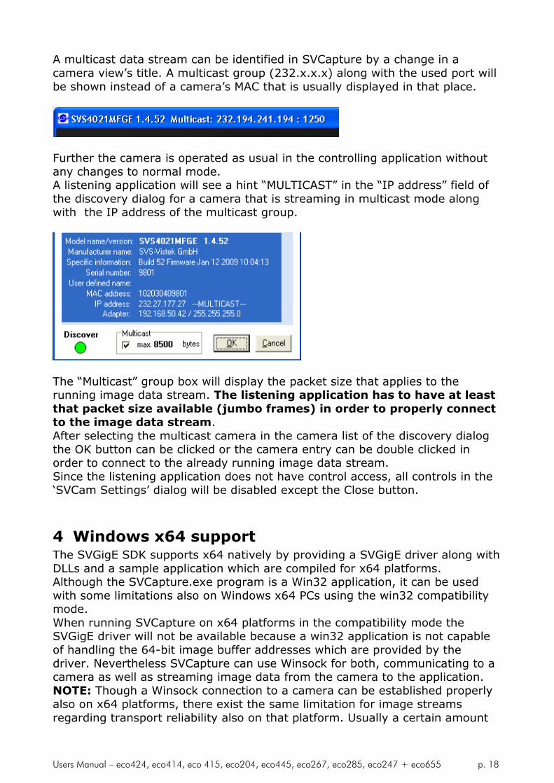
A multicast data stream can be identified in SVCapture by a change in acamera view’s title. A multicast group (232.x.x.x) along with the used port willbe shown instead of a camera’s MAC that is usually displayed in that place.
Further the camera is operated as usual in the controlling application withoutany changes to normal mode.A listening application will see a hint “MULTICAST” in the “IP address” field ofthe discovery dialog for a camera that is streaming in multicast mode alongwith the IP address of the multicast group.
The “Multicast” group box will display the packet size that applies to therunning image data stream. The listening application has to have at leastthat packet size available (jumbo frames) in order to properly connectto the image data stream.After selecting the multicast camera in the camera list of the discovery dialogthe OK button can be clicked or the camera entry can be double clicked inorder to connect to the already running image data stream.Since the listening application does not have control access, all controls in the‘SVCam Settings’ dialog will be disabled except the Close button.
4 Windows x64 supportThe SVGigE SDK supports x64 natively by providing a SVGigE driver along withDLLs and a sample application which are compiled for x64 platforms.Although the SVCapture.exe program is a Win32 application, it can be usedwith some limitations also on Windows x64 PCs using the win32 compatibilitymode.When running SVCapture on x64 platforms in the compatibility mode theSVGigE driver will not be available because a win32 application is not capableof handling the 64-bit image buffer addresses which are provided by thedriver. Nevertheless SVCapture can use Winsock for both, communicating to acamera as well as streaming image data from the camera to the application.NOTE: Though a Winsock connection to a camera can be established properlyalso on x64 platforms, there exist the same limitation for image streamsregarding transport reliability also on that platform. Usually a certain amount
Users Manual – eco424, eco414, eco 415, eco204, eco445, eco267, eco285, eco247 + eco655 p. 19
of network packets gets lost when working over Winsock. Though the GigEVision standard allows for resending lost packets it might be that under certaincircumstances visible failures in images can result from loosing networkpackets dependent on the system load. Therefore the recommended and mostreliable way for streaming image data from a camera to a PC is by using thefilter driver. The SVGigE_ExampleVC8.x64.exe allows for running a connectionwith both, filter driver as well as Winsock and for comparing those modes andtheir main characteristics against each other.
5 Camera settings dialogDouble clicking into the image area or selecting the “Camera settings” entry inthe “Camera” menu brings up a settings dialog that allows for accessing thevarious camera settings:
Note that SVcapture is currently not working under Win XP64 bit or Win 7 64 bit OS.
However, the sample program and driver work well . So itwill not be a problem for a developement.
Users Manual – eco424, eco414, eco 415, eco204, eco445, eco267, eco285, eco247 + eco655 p. 20
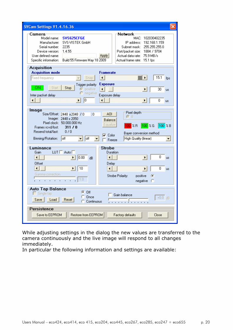
While adjusting settings in the dialog the new values are transferred to thecamera continuously and the live image will respond to all changesimmediately.In particular the following information and settings are available:

Users Manual – eco424, eco414, eco 415, eco204, eco445, eco267, eco285, eco247 + eco655 p. 21
In particular the following information and settings are available:
5.1.1 Camera
In the camera panel the following information is queried from the camera anddisplayed:
Model name: ecoZZZXVGE
Manufacturer name: SVS-VISTEK
Serial number
Device version
User defined name
Manufacturer specific information
5.1.2 Network
The network panel shows the currently used network related settings andparameters. These are in particular:
The camera’s MAC address
The camera’s IP address
The camera’s subnet mask
The camera’s streaming port and streaming packet size
The actual data rate
The actual frame rate
5.1.3 Acquisition
The acquisition panel contains the settings that are related to image acquisitionas follows:
Acquisition mode: (free running, software trigger, external triggerwith internal/external exposure)
Free Running: At the first installation it should be this mode. Inthis mode the camera creates all sync signals itself. There is noneed to trigger the camera (by EXSYNC) in order to get data. TheExposure time can be set by using the software Interface ofthe PC. It is controlled by the internal FPGA. No further externalsignals. The enclosed program allows the user to set the valuesfrom e.g. about 1/100.000/sec to 1 second. Exposure time can bechanged online during operation.
External trigger and using Pulse width of Trigger (externalexposure): In this mode the camera is waiting for an externaltrigger which causes the integration and read out. The exposuretime can be varied by the length of EXSYNC between the highgoing edge and the low going edge. The Time settings in thecontrol menu are not activated. This mode is useful in applications

Users Manual – eco424, eco414, eco 415, eco204, eco445, eco267, eco285, eco247 + eco655 p. 22
where the light level of the scene changes during operation. Aframe to frame variation is allowed. Trigger must be fed directly to
the camera by into the Hirose connector. A TTL (min. 5V)signal is provided from encoder, flashlight or any other source.
Details see Appendix G.
Software triggered and using PC: The frame rate is determinedby the number of Software TRIGGER pulses generated inside thePC per time. With each “Software pulse” the camera will readout aframe. The Exposure time is set as in free running mode. Exposuretime can be changed online during operation.
Frame rate: It allows to alter the frame rate between 1 and thespecified maximum value.
Exposure: The exposure time can be set in µsec. The minimalexposure time is about 50 µsec (depending on the camera type andspeed). The longest is about several seconds (triggered modes). Dueto the internal timing of the camera the program will adjust the valuesto the appropriate values.
Acquisition control (Start/Stop)
Single capture button (Snap)
Exposure (enter values > 2 sec. [2..85 sec.] into the Edit filed)
Exposure delay
Trigger polarity (positive/negative)
Single capture button: Takes a single shot of the actual scene
Inter-packet delay
The inter-packet delay has impact on a camera’s bandwidth usage. A setting ofan inter-packet delay of zero will send all image packets as fast as they areavailable dependent on the camera’s pixel clock, e.g. at 50 MHz. This is thepreferred setting when operating a single camera on a network interface.In case of multiple cameras or other devices working on the same physicalnetwork it might be desirable to send the packets of a camera’s streamingchannel with a certain inter-packet delay in order to allow multiple cameras ordevices to share a given network bandwidth.
NOTE: The inter-packet delay should be below the value which woulddecrease the frame rate.
5.2 Image
The image panel displays information about the picture geometry, the pixelclock and it allows for the following settings:
AOI (area of interest) which can be less or equal the imager size
Binning mode (off, vertical, horizontal, 2x2)No Binning = full resolution: horizontal x 1, vertical x 1 (default setting)H2 x V2 x: vertical 2 x and horizontal 2 x at the same time; Resolution:

Users Manual – eco424, eco414, eco 415, eco204, eco445, eco267, eco285, eco247 + eco655 p. 23
horizontal x ½, vertical x ½, Sensitivity is 4 x, pixel frequency is halved, max.frame rate is almost doubled. “No Binning” sets the camera to full resolution,H1 x 2 and 2 x 1 binning is also available
If you need other binning mode configurations consult factory or your nearestdistributor.
Please note: Using binning with a color version of the camera willcause incorrect colors and strange effects! However, for fastfocusing it might be useful.
Pixel depth (8-bit, 12-bit, 16-bit, if supported by camera)
Color (On/Off)
Bayer method (Disabled, Nearest neighbor, Simple, Bilinear, HQ Linear,Edge Sense, Gray)
Factors for white balance (Red, Green, Blue)
“Balance” button for performing automatic white balance
“Equalize” button for setting all colors to 100%
Freeze (display switched off while acquisition continuous, for testpurposes)
In addition the number of transferred frames is displayed as well as thenumber of eventually lost frames. A frame loss may happen for example incase of an insufficient network bandwidth or if the network connection getsinterrupted for a short time or in case of other network failures.Further the number of resent network packets is displayed. The secondnumber is the last resent packet number and the first number indicates thetotal number of resent packets.
5.3 Gain
The gain panel allows for adjusting gain and autogain (planned) with thefollowing controls:
The default gain setting is “0” dB. You may change the gain up to 6 dB (or higher) in stepsof 1/10th. Note that the dark offset will increase and dynamic range will not be improved.Please note that noise also is amplified. For good image quality do not increase gain morethan 6 dB; higher Gain is possible but not specified!
5.4 Offset
Dark level offset adjustment is possible. When 8 Bit are transmitted it can bechanged from 0 to 255. Please note that factory adjustment is optimized forS/N ratio and sensitivity. You may lose dynamic range. Alter only if youoperate at high temperatures like +40 °C. It can be altered for each channelseparately (for 2 tap Kodak CCDs).
5.5 AutoGain/AutoExposure
When the “Auto” checkbox is activated for cameras that provide for theAutoGain/AutoExposure feature, the “Luminance” panel changes to show thesettings that apply to this mode of operation. The manual settings for gain andoffset will disappear since the luminance will be controlled automatically.The automated luminance control algorithm takes advantage of both, exposureand gain settings. First the exposure will be tried to adjust it such that a set
Users Manual – eco424, eco414, eco 415, eco204, eco445, eco267, eco285, eco247 + eco655 p. 24
brightness value will be met. Once the highest exposure value has beenreached the algorithm will further increase luminance by increasing camera’sgain. The upper and lower limits for both controls are available in the“Luminance” panel once the “Auto” checkbox is checked.The actual exposure is shown on the “Acquisition” panel and the actual gain isdisplayed in the “Luminance” panel on the left to the “min” and “max” gainsettings.
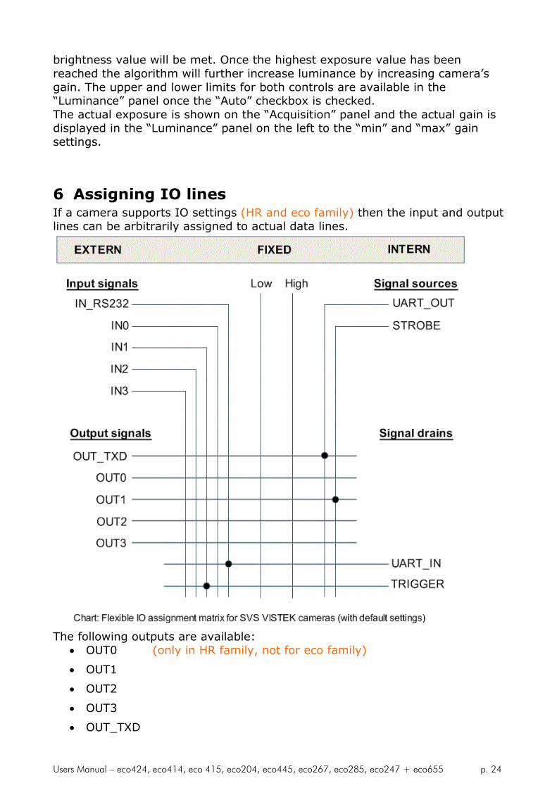
6 Assigning IO linesIf a camera supports IO settings (HR and eco family) then the input and outputlines can be arbitrarily assigned to actual data lines.
The following outputs are available: OUT0 (only in HR family, not for eco family)
OUT1
OUT2
OUT3
OUT_TXD
Users Manual – eco424, eco414, eco 415, eco204, eco445, eco267, eco285, eco247 + eco655 p. 25
Those output lines can be connected to the following signal sources:
UART_OUT
STROBE
any of the input lines
fixed signals Low or High
The following input lines are available:
IN0 (only in HR family, not for eco family)
IN1
IN2
IN3
IN_RS232
The input lines can be connected to the following signal drains:
UART_IN
Trigger
any of the output lines
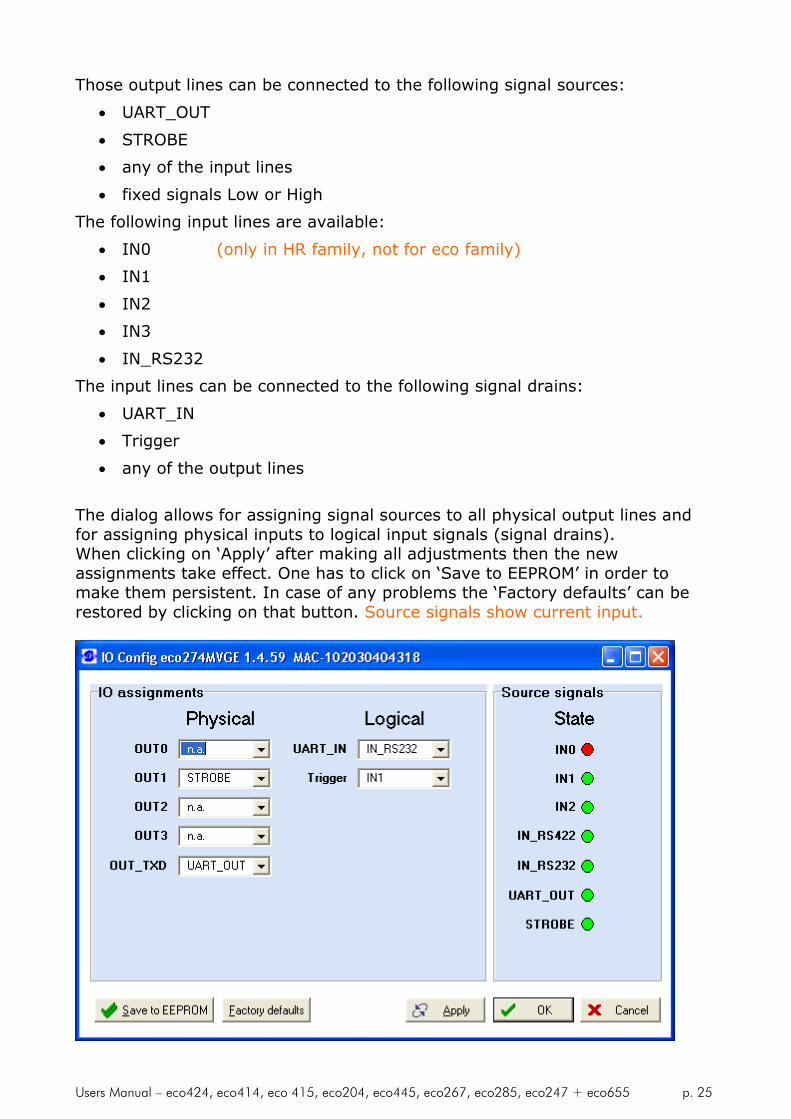
The dialog allows for assigning signal sources to all physical output lines andfor assigning physical inputs to logical input signals (signal drains).When clicking on ‘Apply’ after making all adjustments then the newassignments take effect. One has to click on ‘Save to EEPROM’ in order tomake them persistent. In case of any problems the ‘Factory defaults’ can berestored by clicking on that button. Source signals show current input.

Users Manual – eco424, eco414, eco 415, eco204, eco445, eco267, eco285, eco247 + eco655 p. 26
6.1 Adjusting an AOI (area of interest)
When clicking on the “AOI” button in the “Image” panel a graph tabletbecomes visible that allows for defining an AOI by dragging and resizing agray target area with a red border inside the imager limits, represented by arectangle with black borders.
Whenever the left mouse button is released after dragging/resizing the targetarea, the camera will be adjusted to the new settings. Alternatively the targetarea can be defined numerically by entering values into the edit fields forSize/Offset and subsequently clicking on “Apply”. After clicking on “Apply” thegraph tablet will disappear and the new settings are stored in the camera.
6.2 Strobe
The strobe panel allows for accessing the following settings for controlling lightsources:
Strobe duration
Strobe delay (Start of strobe related to a trigger pulse)
Strobe polarity (positive/negative)
6.3 Persistence
The buttons in the persistence panel allow for saving and restoring all settings: Save to EEPROM
Restore from EEPROM
Factory defaults
Close

Users Manual – eco424, eco414, eco 415, eco204, eco445, eco267, eco285, eco247 + eco655 p. 27
7 Saving images to diskThe live image can be saved to disk with the “Save as” item in the Imagemenu. After selecting a path and specifying a file name a picture in one of theformats JPEG, PNG (Portable Network Graphics), BMP or PIX (raw pixel data)will be saved to disk. Saving of 16-bit images is supported by the PNG and PIX(raw pixel data) formats.

Users Manual – eco424, eco414, eco 415, eco204, eco445, eco267, eco285, eco247 + eco655 p. 28
8 Displaying a camera’s XML fileAccordingly to the GigE Vision standard a GigE camera provides for an XML filethat defines the camera’s capabilities. Though the XML file will usually beprocessed by software, the SVCapture application allows for displaying acamera’s XML file on screen and saving it to disk. This functionality is availablein the “Camera” menu when clicking on the “Show XML file” entry.
Users Manual – eco424, eco414, eco 415, eco204, eco445, eco267, eco285, eco247 + eco655 p. 29
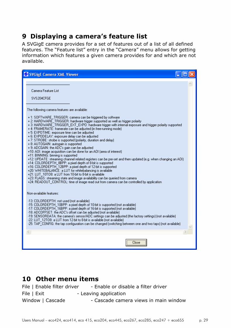
9 Displaying a camera’s feature listA SVGigE camera provides for a set of features out of a list of all definedfeatures. The “Feature list” entry in the “Camera” menu allows for gettinginformation which features a given camera provides for and which are notavailable.
10 Other menu itemsFile | Enable filter driver - Enable or disable a filter driver
File | Exit - Leaving application
Window | Cascade - Cascade camera views in main window

Users Manual – eco424, eco414, eco 415, eco204, eco445, eco267, eco285, eco247 + eco655 p. 30
Window | Tile - Assign each camera view a share of main window
Window | Delete - Close camera view that currently has the focus
About - Program and version information
11 Context menuA context menu can be activated in the image window by right clicking on themouse inside that window. The following functions can be controlled by thismenu:
Displaying pixel coordinates and values
Reducing the size of an image to 12,5%
Reducing the size of an image to 25%
Reducing the size of an image to 50%
Restoring the original 100% size of an image
Magnifying resolution to 200% (image fragment scrolled by left mouseclick)
Magnifying resolution to 400% (image fragment scrolled by left mouseclick)
Magnifying resolution to 800% (image fragment scrolled by left mouseclick)

Users Manual – eco424, eco414, eco 415, eco204, eco445, eco267, eco285, eco247 + eco655 p. 31
If “Pixel values” is selected the display switches in the bottom left corner todisplaying the min and max values at cursor position along with the differencemax-min which represents the image’s noise amplitude at cursor position:
11.1 Filter Driver
In order to lower CPU load on some PCs it is useful to save CPU power forother tasks. The driver delivered with the camera helps to do so. See Fehler!Verweisquelle konnte nicht gefunden werden. for installation.
It is recommended always to enable the filter driver, otherwise imagescan be lost!

Users Manual – eco424, eco414, eco 415, eco204, eco445, eco267, eco285, eco247 + eco655 p. 32
11.2 Firmware update
A separate tool called “Firmware Update Tool.exe” is provided to execute afirmware update.
Depending on the serial number a firmware update for the internalcamera logic might be useful or necessary. This can be essential in order touse the current available SVCapture or SDK.
Using unmatched hardware and software (e.g. HW 1.2 with SW 1.4)will NOT work. Numbering is consistent. So 1.4 SW requires 1.4 firmware!
In doubt please contact your local distributor.
Users Manual – eco424, eco414, eco 415, eco204, eco445, eco267, eco285, eco247 + eco655 p. 33
12 Technical Data
An easy logic allows the control of the camera by different signals to achieveoptimum image quality.
12.1 CCD used/cosmetic issues:
Sony: ICX 424, ICX618, ICX 414, ICX415, ICX204, ICX445, ICX267,
ICX285, ICX274 +ICX655
For Details see Sony ICX datasheets
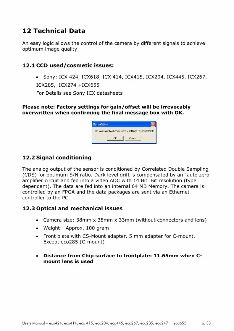
Please note: Factory settings for gain/offset will be irrevocablyoverwritten when confirming the final message box with OK.
12.2 Signal conditioning
The analog output of the sensor is conditioned by Correlated Double Sampling(CDS) for optimum S/N ratio. Dark level drift is compensated by an “auto zero”amplifier circuit and fed into a video ADC with 14 Bit Bit resolution (typedependant). The data are fed into an internal 64 MB Memory. The camera iscontrolled by an FPGA and the data packages are sent via an Ethernetcontroller to the PC.
12.3 Optical and mechanical issues
Camera size: 38mm x 38mm x 33mm (without connectors and lens)
Weight: Approx. 100 gram
Front plate with CS-Mount adapter. 5 mm adapter for C-mount.Except eco285 (C-mount)
Distance from Chip surface to frontplate: 11.65mm when C-mount lens is used

Users Manual – eco424, eco414, eco 415, eco204, eco445, eco267, eco285, eco247 + eco655 p. 34
Views on Camera eco424, 415, eco204,eco445, eco267,eco274 svs655 front plate with CS-Mount adapter.
svs285 has front plate with C-Mount adapter.Actually showing C-mount
( Difference from CS to C-mount is + 5mm)
Use 4 x M3 holes in frontplate for mounting !!!Proper heatsinking is required !!

Users Manual – eco424, eco414, eco 415, eco204, eco445, eco267, eco285, eco247 + eco655 p. 35
HR10A-10R-12PB (mating connector HR10A-10P-12S)
1 VIN- (GND)2 VIN+ (10 to 25VDC)3 RXD data to camera (RS232 Level)4 TXD data from camera (RS232 Level)5 IN1 ( 0- 24 V) digital6 IN2 ( 0- 24 V) digital7 OUT1 (open drain max 24 V, 0.3 A) digital8 OUT2 (open drain max 24 V, 0.3 A) digital9 IN3+ (RS422 Level)10 IN3- (RS422 Level)11 OUT3 + (RS422 Level)12 OUT3- (RS422 Level)
Option
Mounting Bracket ( do not scale)

Users Manual – eco424, eco414, eco 415, eco204, eco445, eco267, eco285, eco247 + eco655 p. 36
Basic electro-optic Specifications of Cameras
eco424
CCD ICX 424 1/3”Interline
640 x 480 PixelPixel Size 7.4 x 7.4µm
Pixelclock 1 x 50 MHz
Frame Rate (max.) 124 fps
Frame Rate (2 x 2Binning)
Offset ca. 40 counts in 12 Bit
Gain 18 db
S/N Ratio> 56dB (9,0 Bit),(Saturation/Dark Noise(RMS))
Fixed Pattern Noise ca. 8 counts in 12 Bit
Photo Response Non-uniformity (PRNU)
+/- 10%
Spectral Response 380 – 950 nm Monochrome
Exposure Time (internal) 3 µsec – 2 sec
Power consumption 3.3W (0.27A @ 12V)
eco414
CCD ICX 424 1/2”Interline
640 x 480 PixelPixel Size 9.9 x 9.9µm
Pixelclock 1 x 50 MHz
Frame Rate (max.) 125 fps
Frame Rate (2 x 2Binning)
Offset ca. 40 counts in 12 Bit
Gain 18 db
S/N Ratio> 58dB (9.5 Bit),(Saturation/Dark Noise(RMS))
Fixed Pattern Noise ca. 8 counts in 12 Bit
Photo Response Non-uniformity (PRNU)
+/- 10%
Spectral Response 380 – 950 nm Monochrome
Exposure Time (internal) 21 µsec – 2 sec
Power consumption 3.5W (0.29A @ 12V)

Users Manual – eco424, eco414, eco 415, eco204, eco445, eco267, eco285, eco247 + eco655 p. 37
eco618
CCD ICX 618 1/4”Interline
640 x 480 PixelPixel Size 5,6 x 5.6µm
Pixelclock 1 x 65 MHz
Frame Rate (max.) 160 fps
Frame Rate (2 x 2Binning)
Offset ca. 40 counts in 12 Bit
Gain 18 db
S/N Ratio> 58 dB (9,5 Bit),(Saturation/Dark Noise(RMS))
Fixed Pattern Noise ca. 8 counts in 12 Bit
Photo Response Non-uniformity (PRNU)
+/- 10%
Spectral Response 380 – 950 nm Monochrome
Exposure Time internal) 65 µsec – 2 sec
Power consumption 3.3W (0.27A @ 12V)
eco415
CCD ICX 415 1/2”Interline
780 x 580 Pixel Pixel Size 8.3 x 8,3 µm
Pixelclock 1 x 50 MHz
Frame Rate (max.) 86 fps
Frame Rate(2 x 2 Binning)
Offset ca. 40 counts in 12 Bit
Gain 18 db
S/N Ratio> 58dB (9.5 Bit),(Saturation/DarkNoise (RMS))
Fixed Pattern Noise ca. 8 counts in 12 Bit
Photo Response Non-uniformity (PRNU)
+/- 10%
Spectral Response 380 – 950 nm Monochrome
Exposure Time (internal) 21 µsec – 2 sec
Power consumption 3.3W (0.29A @ 12V)

Users Manual – eco424, eco414, eco 415, eco204, eco445, eco267, eco285, eco247 + eco655 p. 38
eco204
CCD ICX 204 1/3”Interline
1024 x 768 PixelPixel Size 4,65 x 4,65µm
Pixelclock 1 x 50 MHz
Frame Rate (max.) 47 fps
Frame Rate (2 x 2Binning)
Offsetca. 40 counts in 12Bit
Gain 18 db
S/N Ratio> 54dB (9 Bit),(Saturation/DarkNoise (RMS))
Fixed Pattern Noiseca. 40 counts in 12Bit
Photo Response Non-uniformity (PRNU)
+/- 10%
Spectral Response 380 – 950 nm Monochrome
Exposure Time (internal) 16 µsec – 2 sec
Power consumption 3.0W (0.28A @ 12V)
eco445
CCD ICX 204 1/3”Interline
1280 x 960 PixelPixel Size 3,75 x 3,75µm
Pixelclock 1 x 50 MHz
Frame Rate (max.) 30 fps
Frame Rate (2 x 2Binning)
Offsetca. 40 counts in 12Bit
Gain 18 db
S/N Ratio> 56dB (9 Bit),(Saturation/DarkNoise (RMS))
Fixed Pattern Noiseca. 40 counts in 12Bit
Photo Response Non-uniformity (PRNU)
+/- 10%
Spectral Response 380 – 950 nm Monochrome
Exposure Time (internal) 12 µsec – 2 sec
Power consumption 2.5W (0.28A @ 12V)
Users Manual – eco424, eco414, eco 415, eco204, eco445, eco267, eco285, eco247 + eco655 p. 39
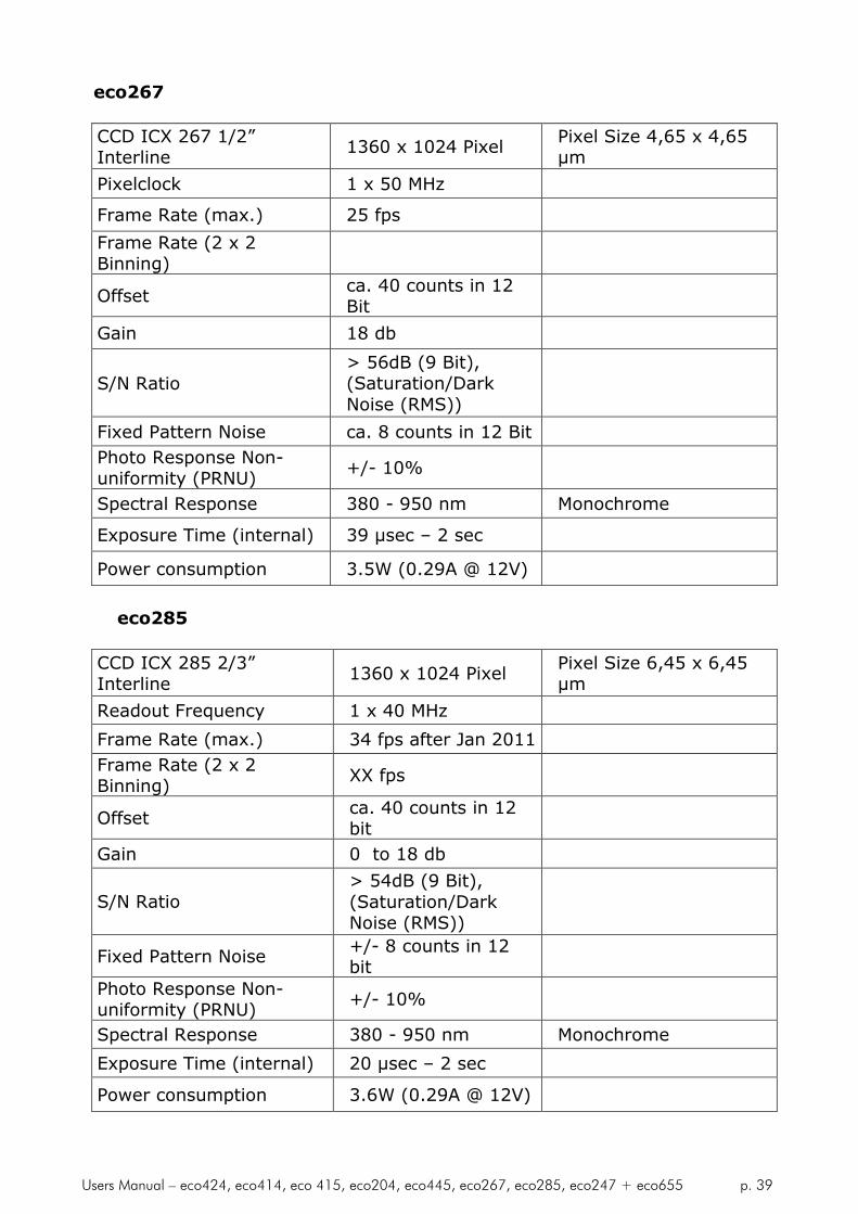
eco267
CCD ICX 267 1/2”Interline
1360 x 1024 PixelPixel Size 4,65 x 4,65µm
Pixelclock 1 x 50 MHz
Frame Rate (max.) 25 fps
Frame Rate (2 x 2Binning)
Offsetca. 40 counts in 12Bit
Gain 18 db
S/N Ratio> 56dB (9 Bit),(Saturation/DarkNoise (RMS))
Fixed Pattern Noise ca. 8 counts in 12 Bit
Photo Response Non-uniformity (PRNU)
+/- 10%
Spectral Response 380 - 950 nm Monochrome
Exposure Time (internal) 39 µsec – 2 sec
Power consumption 3.5W (0.29A @ 12V)
eco285
CCD ICX 285 2/3”Interline
1360 x 1024 PixelPixel Size 6,45 x 6,45µm
Readout Frequency 1 x 40 MHz
Frame Rate (max.) 34 fps after Jan 2011
Frame Rate (2 x 2Binning)
XX fps
Offsetca. 40 counts in 12bit
Gain 0 to 18 db
S/N Ratio> 54dB (9 Bit),(Saturation/DarkNoise (RMS))
Fixed Pattern Noise+/- 8 counts in 12bit
Photo Response Non-uniformity (PRNU)
+/- 10%
Spectral Response 380 - 950 nm Monochrome
Exposure Time (internal) 20 µsec – 2 sec
Power consumption 3.6W (0.29A @ 12V)

Users Manual – eco424, eco414, eco 415, eco204, eco445, eco267, eco285, eco247 + eco655 p. 40
eco274
CCD ICX 274 1/2”Interline
1600 x 1200 Pixel Pixel Size 4,4 x 4,4 µm
Pixelclock 1 x 50 MHz
Frame Rate (max.) 26 fps after Jan 2011
Frame Rate (2 x 2Binning)
Offsetca. 40 counts in 12Bit
Gain 0 to 18 dB
S/N Ratio> 54dB (9 Bit),(Saturation/DarkNoise (RMS))
Fixed Pattern Noise ca. 8 counts in 12 Bit
Photo Response Non-uniformity (PRNU)
+/- 10%
Spectral Response 380 - 950 nm Monochrome
Exposure Time (internal) 26 µsec – 2 sec
Power consumption 3.7W (0.32A @ 12V)
eco655
CCD ICX 655 2/3”Interline
2448 x 2050 PixelPixel Size 3,45 x 3,45µm
Readout Frequency 1x 50 MHz
Frame Rate (max.) 10 fps
Frame Rate (2 x 2Binning)
18 fps
Offsetca. 40 counts in 12Bit
Gain 0 to 18 db
S/N Ratio> 58dB (9.5 Bit),(Saturation/DarkNoise (RMS))
Fixed Pattern Noise < 8 count in 12 Bit
Photo Response Non-uniformity (PRNU)
+/- 10%
Spectral Response 380 – 950 nm Monochrome
Exposure Time (internal) 7 µsec – 1 sec
Power consumption 3.1W (0.29A @ 12V)

Users Manual – eco424, eco414, eco 415, eco204, eco445, eco267, eco285, eco247 + eco655 p. 41
12.4 Environmental Issues
4.8.1 EuropeThe camera is CE tested and the rules of EN 50022-2 apply.
4.8.2 USA and CanadaI. Labeling requirements:This device complies with part 15 of the FCC Rules. Operation is subject to thefollowing two conditions: (1) This device may not cause harmful interference,and (2) this device must accept any interference received, includinginterference that may cause undesired operation.
II. Information to the user:Note: This equipment has been tested and found to comply with the limits fora Class A digital device, pursuant to part 15 of the FCC Rules. These limits aredesigned to provide reasonable protection against harmful interference whenthe equipment is operated in a commercial environment. This equipmentgenerates, uses, and can radiate radio frequency energy and, if not installedand used in accordance with the instruction manual, may cause harmfulinterference to radio communications. Operation of this equipment in aresidential area is likely to cause harmful interference in which case the userwill be required to correct the interference at his own expense.
It is necessary to use a shielded power supply cable. You can than use the“shield contact” on the connector which has GND contact to the camerahousing. This is essential for any use. If not done and camera is destroyed dueto Radio Magnetic Interference (RMI) WARRANTY is void!
Operating temperature Spec: -10 to +40 °CIn order to keep dark current low. To achieve 9 optical Bit, operationat 25 °C max. is recommended.
Power: US/UK and European line adapter can bedelivered. Otherwise use +10 to +24V DC with filtered and stabilizedpower supply.
Shock is tested: About 60 g in 6 ms. Vibration test is 10 g in 6 ms
RoHS: All cameras comply with the recommendation of the EuropeanUnion concerning RoHS Rules.

Users Manual – eco424, eco414, eco 415, eco204, eco445, eco267, eco285, eco247 + eco655 p. 42
12.5 Spectral response curves
Monochrome Version All Color Versioneco424, eco414, eco415,eco204, eco267, eco247,eco655
0.0
0.1
0.2
0.3
0.4
0.5
0.6
0.7
0.8
0.9
1.0
400 500 600 700 800 900 1000
Wavelength [nm]
Re
lativ
ere
spo
nse
Wavelength [nm]
Re
lativ
ere
spo
nse
0.0
0.2
0.4
0.6
0.8
1.0
400 450 500 550 600 650 700
eco285
eco618

Users Manual – eco424, eco414, eco 415, eco204, eco445, eco267, eco285, eco247 + eco655 p. 43
Comments on camera temperature
There is no need to worry because the camera has been tested at highertemperatures than specified (40 °C).
12.6 Comments on Color Version
If you have purchased a color version (e.g. ecoZZZXVGE) of this camera,please note the following:
In all electrical terms the camera is identical to the black and white versions.
The camera uses a CCD which has a color mosaic filter. This filter is called"Bayer"-filter named after the person who invented it. It has a pattern on thelines which alternates as follows, e.g.:
First line: RGRGRG.... and so on (R = Red, B = Blue, G = Green)Second line: GBGBGB.... and so on
Please note that about half of the pixel are green, a quarter red and a quarterblue. This is due to the maximum sensitivity of the human eye at about 550 nm(green).
Note that the green pixel in the “red” line has different sensitivity thanthe green pixel in the “blue” line.
Because this camera is a single chip camera it is necessary to use an algorithmwhich interpolates those colors which are "not known" by the specific pixel. E.g.the red pixel does not know its green and blue components.
This means that the performance of the image depends on the software used.
Please be aware that it is not possible to incorporate the algorithm into thecamera so easily. Unlike NTSC/PAL cameras there is no hardware chip availablewhich can do that for such large images. The user has the advantage to alterthe colors depending on his needs. Thus the color image must be processed inthe PC.
We offer several algorithms in the SVCapture program which influence displayrate and image quality. However a color source code is available on request forthose who want to write an application.
We offer a complete set for a system setup containing camera, cable, powersupply, and software to help solving your applications.
Note that you can disable the color in the SVCapture program. Colorprocessing is not done inside the camera but in the PC. So some CPUpower is consumed.
If you have questions do not hesitate to contact us or your local dealer.

Users Manual – eco424, eco414, eco 415, eco204, eco445, eco267, eco285, eco247 + eco655 p. 44
13 Warranty Terms
13.1 Standard products warranty and adjustment
Seller warrants that the article to be delivered under this order will be freefrom detects in material and workmanship under normal use and service for aperiod of TWO years from date of shipment. The liability of Seller under thiswarranty is limited solely to replacing or repairing or issuing credit (at thediscretion for Seller) for such products that become defective during thewarranty period.
In order to permit Seller to properly administer this warranty, Buyer shallnotify Seller promptly in writing of any claims,; provide Seller with anopportunity to inspect and test the products claimed to be detective. Suchinspection may be on customer’s premises or Seller may request return of suchproducts at customer’s expense. Such expense will subsequently bereimbursed to customer if the product is found to be defective and Buyer shallnot return any product without prior return authorization from Seller.
If a returned product is found to be out of warranty or found to be within theapplicable specification, Buyer will have to pay an evaluation and handlingcharge, independent of possible repair and/or replacement costs. Seller willnotify Buyer of the amount of said evaluation and handling charges at the timethe return authorization is issued. The Seller will inform the Buyer of relatedrepair and/or replacement costs and request authorization before incurringsuch costs. Buyer shall identify all returned material with Sellers invoicenumber, under which material has been received.
If more than one invoice applies, material has to be clearly segregated andidentified by applicable invoice numbers. Adjustment is contingent upon Sellersexamination of product, disclosing that apparent defects have not been causedby misuse, abuse, improper installation of application, repair, alteration,accident or negligence in use, storage, transportation or handling. In no eventshall Seller be liable to Buyer for loss of profits, loss of use, or damages of anykind based upon a claim for breach of warranty.
13.2 Development Product Warranty
Developmental products of Seller are warranted to be free from defects inmaterials and workmanship and to meet the applicable preliminaryspecification only at the time of receipt by Buyer and for no longer period oftime in all other respects the warranties made above apply to developmentproducts.
The aforementioned provisions do not extend the original warranty period ofany article which has been repaired or replaced by Seller. If Warranty Label ofcamera is broken Warranty is void!

Users Manual – eco424, eco414, eco 415, eco204, eco445, eco267, eco285, eco247 + eco655 p. 45
SELLER MAKES NO OTHER WARRANTIES; EXPRESS OR IMPLIED; ANDSPECIFICALLY; SELLER MAKES NO WARRANTY OF MERCHANTABILITY OFFITNESS FOR PARTICULAR PURPOSE.

Users Manual – eco424, eco414, eco 415, eco204, eco445, eco267, eco285, eco247 + eco655 p. 46
14 Appendix A – Troubleshooting
14.1 Get camera diagnostics
When clicking on the Camera | Diagnostics menu entry a dialog will open thatallows for receiving camera diagnostics information.
The content of the Diagnostics window is low level register information. Usuallyit is needed only for remote analysis purposes of problem situations.
The following items provide some hints how to solve problem situations wherea connection between a PC and a camera can not be established successfully.

Users Manual – eco424, eco414, eco 415, eco204, eco445, eco267, eco285, eco247 + eco655 p. 47
Problem: A camera does not appear in the discovery dialog
Solutions: Click on “Refresh” in order to repeat the Discovery action.Disconnect and reconnect the camera’s power cable andrepeat the Discovery action after a few seconds. Make surethe PC has got a valid IP address.Shutdown and restart thePC and repeat the Discovery action. Check firewall settings(See “Firewall considerations” below).
Problem: A camera does not display a picture after it has beendiscovered and selected
Solutions: Force a valid IP address in to the camera using the dialogthat comes up when right- clicking on an entry in thediscovery dialog. Close the camera view and select thecamera again in the Discovery dialog. Shutdown and restartthe PC and select the camera again after discovery. Checkfirewall settings (e.g. disable firewall temporarily and selectthe camera again after discovery). Check if the processorspeed of the PC is sufficient for displaying images at thechosen frame rate. If available, connect the camera to adifferent network card.
Problem: No communication is possible between the camera andthe PC
Solution: Check if a firewall is active. This can prevent to establish anycommunication because this is a network issue check firewallsetting. Try to disable temporary the firewall and try again.
Problem: The video stream stops when adjusting the camera settings
Solution: This situation happens when the product between frame rateand exposure time becomes 1 second or greater. Any of thesettings can be reduced in order to get the cameraoperational again. The exposure settings field will becomered in order to signal that one of the frame rate or exposuresetting has to be reduced.
Problem: Camera does not respond to light
Solution: Please execute following steps:Check if camera is in a “Free Running”-mode. When done,check with “SVCapture” program if you can read back anydata from the camera like: Type of CCD, S/N numberexposure time settings and so on. If you trigger the cameraby hardware: Check if the Exsync signal is present. Thesignal swing for must be minimum 5V (max. 24V) Sourcemust provide 10 mA. Below such level the drivers in thecamera will not work. Check also the quality and swing. Ifthese signals are not there or do not have the right quality

Users Manual – eco424, eco414, eco 415, eco204, eco445, eco267, eco285, eco247 + eco655 p. 48
(like spikes) the camera can not read out any frame ordelivers distorted images.
Problem: The image is present but distorted
Solution: Try different operation mode. Like if triggered gives badresults try “Free Running” mode and reduce frame rate tominimum half possible one. Check if you are using original“INTEL”® chip set in your PC! If problem still exist call yourlocal support.
Problem: The image of a color version camera looks “ugly” orfalse colors appear.
Solution: If the raw image looks ok than pixel need to be shifted byeither one or one line. The image color depends on thealgorithm used. If the algorithm is starting with the wrongpixel such effects appear.
Problem: The colors of a color version are not perfect especiallywhen using halogen light
Solution: Halogen light contains strong portions of IR radiation. Usecut off filters at around 730 nm like Schott KG 3 to preventIR radiation reaching the CCD.
Problem: You use 64 bit OS system, but SVcapture does notwork
Solution: This is normal. Intead pls check the sample programs inSDK. They will wok without problem.

Users Manual – eco424, eco414, eco 415, eco204, eco445, eco267, eco285, eco247 + eco655 p. 49
15 Troubleshooting Request List V1.3
Dear valued customer,
In order to help you with your camera and any interfacing problems we
request that you fill in a description of your problems when you use the
camera. Please fax this form to us:
1) Type of camera (e.g. eco247XVGE)
2) Serial Number
3) Accessories used and where purchased or self made
a) Power supply
b) Cable
c) Lens type and focal length
4) Firmware version as well as operation mode, (send screenshot of
SVCapture program)
5) Description of the phenomena, e.g.:
a) missing lines or columns
b) distorted or noisy image (if possible send jpg image)
c) solarization effect
d) missing Bit, contrast less image
6) PC used, Chip Set/Brand and type of Ethernet card
7) Operating system used, e.g. WIN/XP/7/Linux

Users Manual – eco424, eco414, eco 415, eco204, eco445, eco267, eco285, eco247 + eco655 p. 50
16 Appendix B – Basic timing for different operationmodes
16.1 Free Running
A frame is readout automatically. There is no need to trigger the camera inorder to get data. The enclosed software allows the user to set exposure timein µSec. The time set stays resident after power off if the configuration issaved to camera if stored before.
16.2 External Trigger and Pulsewidth of Trigger
In this mode the camera is waiting for an external trigger which startsintegration and read out. Exposure time can be varied using the length of theTrigger pulse (I.E. between the high going edge and the low going edge). Thetime settings in the control software are not activated. This mode is useful inapplications where the light level of the sceen changes during operation andthe framegrabber can provide such a signal. Change of exposure time ispossible from one frame to the next.
16.3 External and Software trigger and internal exposure timesetting
The frame rate is determined by the number of Trigger pulses per time unit.With each positive transition (going high) the camera will readout a frame.Exposuretime is set in the same way as in the free running mode. Exposuretime can be changed online during operation. The time set stays resident afterpower off, if the configuration is saved to the camera.
Data
Exposuretime
Trigger
Data
Exposuretime
Data
Exposuretime
Trigger

Users Manual – eco424, eco414, eco 415, eco204, eco445, eco267, eco285, eco247 + eco655 p. 51
17 Appendix C: SDK Description for Camera Control
SVGigE API
GigE Vision CameraSoftware Development Kit (SDK)
Version: 1.4.18.42Date: 2009-09-24

Users Manual – eco424, eco414, eco 415, eco204, eco445, eco267, eco285, eco247 + eco655 p. 52
17.1 Overview
The GigE Vision standard is an award-winning specification for connectingcameras to computers by a Gigabit Ethernet cable. That type of connection iswell suited for transferring the huge data streams that are usually related toimage capturing devices. The current SVS GigE API software development kit(SDK) provides for integrating GigE cameras into own applications.
17.2 Prerequisites
In order to give an example for data transfer requirements, a camera with aresolution of 1600 by 1200 pixels and which is running at 35 frames persecond will generate a data stream of 1600 x 1200 x 35 = 67,2 Mbytes persecond. The bandwidth of the network connection must be capable oftransferring the image data stream from the camera to the client computerwith the image viewing or processing application.Before a GigE camera can be successfully used in a system, all networkparameters have to be adjusted to appropriate settings. This will be done bythe SVCapture program which usage is described in the “SVCapture userguide” document. A successful work with the SVS GigE API softwaredevelopment kit can be accomplished only when it has been proved that acamera can be operated over the network on full frame rate from the PC wherethe software development takes place.
17.3 SVGigE SDK components
The SVGigE SDK consists of the following components: SVGigE.h
SVGigE.cpp
SVGigE.dll
SVGigE.sys
SVGigETLFilter.dll
SVGigETLWinsock.dll
SVGigE SDK user guide.pdf (this document)
The DLL components have to be in the same directory as the executableor alternatively they can be put into the windows\system32 directory. Theheader file and the cpp file will usually be put into the development directories.They are needed for developing applications under various developmentenvironments.Before running the SVGigEFilter.dll the SVGigE driver has to be installedaccordingly to the instructions in the “SVCapture user guide” documentation.
Users Manual – eco424, eco414, eco 415, eco204, eco445, eco267, eco285, eco247 + eco655 p. 53
17.4 Development environments
The SVGigE SDK has been designed as DLL components (one API and twotransport layers: filter driver and winsock based) which export C-stylefunctions to be used by applications. A cpp file is provided in the SDK whichimplements the more than 100 functions that constitute the SVGigE API. Thecpp file forwards function calls from the software application to thecorresponding functions that are contained in the API-DLL module. For thispurpose the DLL modules will be loaded once when the first function callarrives in the API.The chosen programming interface of the API-DLL module is the least commondenominator which should ensure a broad applicability of the DLL module inmost programming environments that can compile C code. Three exampleapplications are currently provided that comprise the Borland C++ Builder 6environment, the Microsoft VisualStudio 6 as well as the Microsoft VisualStudio 2005 environments.The example applications show how to get a handle on a camera in the ownnetwork, how to adjust settings like frame rate and exposure time as well ashow to receive the image data stream by a callback function in the application.For demonstration purposes the image data stream is being displayed onscreen as a live image from the selected camera.
17.5 Windows x64 support
The SVGigE SDK supports 64-bit platforms. All functions in the SVGigE APIapply to x64 platforms in the same way as they do for Win32 platforms.Although win32 applications like SVCapture.exe are also supported on x64platforms in the compatibility mode, there exists a set of runtime componentsthat run natively on x64 platforms:
x64\SVGigE.sys – a filter driver for high-performance image streaming
SVGigETLFilter.x64.dll – a transport layer DLL for the SVGigE driver
SVGigETLWinsock.x64.dll – a transport layer DLL based on Winsock
SVGigE.x64.dll – the SVGigE API DLL used by camera applications
SVGigE_ExampleVC8.x64.exe – a sample application using all listedcomponents
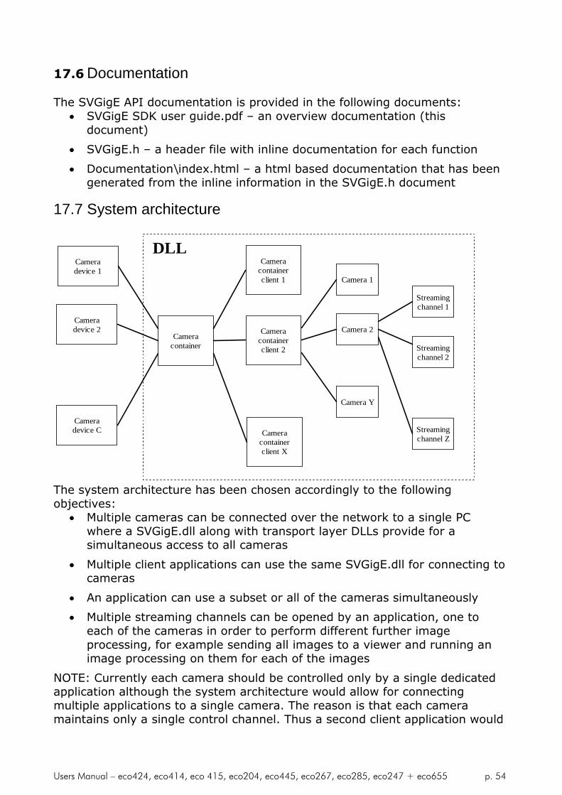
Users Manual – eco424, eco414, eco 415, eco204, eco445, eco267, eco285, eco247 + eco655 p. 54
17.6 Documentation
The SVGigE API documentation is provided in the following documents: SVGigE SDK user guide.pdf – an overview documentation (this
document)
SVGigE.h – a header file with inline documentation for each function
Documentation\index.html – a html based documentation that has beengenerated from the inline information in the SVGigE.h document
17.7 System architecture
Cameradevice 1
Cameradevice C
Cameradevice 2
Cameracontainer
Cameracontainerclient 1
Cameracontainerclient X
Cameracontainerclient 2
Camera 1
Camera 2
Camera Y
DLL
Streamingchannel 1
Streamingchannel Z
Streamingchannel 2
The system architecture has been chosen accordingly to the followingobjectives:
Multiple cameras can be connected over the network to a single PCwhere a SVGigE.dll along with transport layer DLLs provide for asimultaneous access to all cameras
Multiple client applications can use the same SVGigE.dll for connecting tocameras
An application can use a subset or all of the cameras simultaneously
Multiple streaming channels can be opened by an application, one toeach of the cameras in order to perform different further imageprocessing, for example sending all images to a viewer and running animage processing on them for each of the images
NOTE: Currently each camera should be controlled only by a single dedicatedapplication although the system architecture would allow for connectingmultiple applications to a single camera. The reason is that each cameramaintains only a single control channel. Thus a second client application would

Users Manual – eco424, eco414, eco 415, eco204, eco445, eco267, eco285, eco247 + eco655 p. 55
not get a handle on the camera as long as another client maintains a controlchannel to that camera.Looking at the system architecture it should become obvious that the DLLneeds a handle for performing operations on a camera container, on a cameraor on a streaming channel respectively. The client application will obtain thosehandles when registering for a camera container client, a camera or astreaming channel respectively. Those handles have to be stored locally and beused in all subsequent function calls to the different areas in the DLL. Allhandles will be valid until closure activities will be performed for a streamingchannel, a camera or a camera container client respectively.
17.8 Function groups
* Function categories:* ---------------------------------------------------------* 1 - Camera: Discovery and bookkeeping* 2 - Camera: Connection* 3 - Camera: Information* 4 - Stream: Channel control and statistics* 5 - Stream: Transfer parameters* 6 - Stream: Image access* 7 - Stream: Image conversion* 8 - Stream: Image characteristics* 9 - Stream: Image statistics* 10 - Stream: Messaging channel* 11 - Controlling camera: Frame rate* 12 - Controlling camera: Exposure* 13 - Controlling camera: Gain and offset* 14 - Controlling camera: Auto gain/exposure* 15 - Controlling camera: Acquisition trigger* 16 - Controlling camera: Strobe* 17 - Controlling camera: Tap balance* 18 - Controlling camera: Image parameter* 19 - Controlling camera: Image appearance* 20 - Special control: IOMux configuration* 21 - Special control: IO control* 22 - Special control: Serial communication* 23 - Special control: Direct register and memory access* 24 - Special control: Persistent settings and recovery* 25 - General functions* 26 - Diagnostics* ---------------------------------------------------------* 99 - Deprecated functions

Users Manual – eco424, eco414, eco 415, eco204, eco445, eco267, eco285, eco247 + eco655 p. 56
17.9 Detailed function listing
** 0 - GigE DLL (implicitly called)* ---------------------------------* isVersionCompliantDLL()* isLoadedGigEDLL()* getCamera()** 1 - Camera: Discovery and bookkeeping* -------------------------------------* CameraContainer_create()* CameraContainer_delete()* CameraContainer_discovery()* CameraContainer_getNumberOfCameras()* CameraContainer_getCamera()* CameraContainer_findCamera()** 2 - Camera: Connection* ----------------------* Camera_openConnection()* Camera_closeConnection()* Camera_setIPAddress()* Camera_forceValidNetworkSettings()** 3 - Camera: Information* ----------------------* Camera_getManufacturerName()* Camera_getModelName()* Camera_getDeviceVersion()* Camera_getManufacturerSpecificInformation()* Camera_getSerialNumber()* Camera_setUserDefinedName()* Camera_getUserDefinedName()* Camera_getMacAddress()* Camera_getIPAddress()* Camera_getSubnetMask()* Camera_getPixelClock()* Camera_isCameraFeature()* Camera_readXMLFile()** 4 - Stream: Channel control and statistics* ------------------------------------------* StreamingChannel_create()* StreamingChannel_delete()* StreamingChannel_getBufferInfo()* StreamingChannel_setReadoutTransfer()* StreamingChannel_getReadoutTransfer()

Users Manual – eco424, eco414, eco 415, eco204, eco445, eco267, eco285, eco247 + eco655 p. 57
* StreamingChannel_getFrameLoss()* StreamingChannel_getActualFrameRate()* StreamingChannel_getActualDataRate()* StreamingChannel_getPeakDataRate()** 5 - Stream: Transfer parameters* -------------------------------* Camera_evaluateMaximalPacketSize()* Camera_setStreamingPacketSize()* Camera_setInterPacketDelay()* Camera_getInterPacketDelay()* Camera_setMulticastMode()* Camera_getMulticastMode()* Camera_getMulticastGroup()** 6 - Stream: Image access* ------------------------* Image_getDataPointer()* Image_getBufferIndex()* Image_getSignalType()* Image_getCamera()* Image_release()** 7 - Stream: Image conversion* ----------------------------* Image_getImageRGB()* Image_getImageGray()* Image_getImage12bitAs8bit()* Image_getImage12bitAs16bit()* Image_getImage16bitAs8bit()** 8 - Stream: Image characteristics* ---------------------------------* Image_getSizeX()* Image_getSizeY()* Image_getPitch()* Image_getImageSize()* Image_getPixelType()** 9 - Stream: Image statistics* ----------------------------* Image_getImageID()* Image_getTimestamp()* Image_getTransferTime()* Image_getPacketCount()* Image_getPacketResend()** 10 - Stream: Messaging channel* ------------------------------

Users Manual – eco424, eco414, eco 415, eco204, eco445, eco267, eco285, eco247 + eco655 p. 58
* Stream_createEvent()* Stream_addMessageType()* Stream_removeMessageType()* Stream_isMessagePending()* Stream_registerEventCallback()* Stream_unregisterEventCallback()* Stream_getMessage()* Stream_getMessageData()* Stream_getMessageTimestamp()* Stream_releaseMessage()* Stream_flushMessages()* Stream_closeEvent()** 11 - Controlling camera: Frame rate* -----------------------------------* Camera_setFrameRate()* Camera_getFrameRate()* Camera_getFrameRateMin()* Camera_getFrameRateMax()* Camera_getFrameRateRange()* Camera_getFrameRateIncrement()** 12 - Controlling camera: Exposure* ---------------------------------* Camera_setExposureTime()* Camera_getExposureTime()* Camera_getExposureTimeMin()* Camera_getExposureTimeMax()* Camera_getExposureTimeRange()* Camera_getExposureTimeIncrement()* Camera_setExposureDelay()* Camera_getExposureDelay()* Camera_getExposureDelayMax()* Camera_getExposureDelayIncrement()** 13 - Controlling camera: Gain and offset* ----------------------------------------* Camera_setGain()* Camera_getGain()* Camera_getGainMax()* Camera_getGainMaxExtended()* Camera_getGainIncrement()* Camera_setOffset()* Camera_getOffset()* Camera_getOffsetMax()** 14 - Controlling camera: Auto gain/exposure* -------------------------------------------* Camera_setAutoGainEnabled()

Users Manual – eco424, eco414, eco 415, eco204, eco445, eco267, eco285, eco247 + eco655 p. 59
* Camera_getAutoGainEnabled()* Camera_setAutoGainBrightness()* Camera_getAutoGainBrightness()* Camera_setAutoGainDynamics()* Camera_getAutoGainDynamics()* Camera_setAutoGainLimits()* Camera_getAutoGainLimits()* Camera_setAutoExposureLimits()* Camera_getAutoExposureLimits()** 15 - Controlling camera: Acquisition trigger* --------------------------------------------* Camera_setAcquisitionControl()* Camera_getAcquisitionControl()* Camera_setAcquisitionMode()* Camera_setAcquisitionModeAndStart()* Camera_getAcquisitionMode()* Camera_softwareTrigger()* Camera_softwareTriggerID()* Camera_softwareTriggerIDEnable()* Camera_setTriggerPolarity()* Camera_getTriggerPolarity()** 16 - Controlling camera: Strobe* -------------------------------* Camera_setStrobePolarity()* Camera_getStrobePolarity()* Camera_setStrobePosition()* Camera_getStrobePosition()* Camera_getStrobePositionMax()* Camera_getStrobePositionIncrement()* Camera_setStrobeDuration()* Camera_getStrobeDuration()* Camera_getStrobeDurationMax()* Camera_getStrobeDurationIncrement()** 17 - Controlling camera: Tap balance* ------------------------------------* Camera_saveTapBalanceSettings()* Camera_loadTapBalanceSettings()* Camera_setTapConfiguration()* Camera_getTapConfiguration()* Camera_setAutoTapBalanceMode()* Camera_getAutoTapBalanceMode()* Camera_setTapBalance()* Camera_getTapBalance()** 18 - Controlling camera: Image parameter* ---------------------------------------

Users Manual – eco424, eco414, eco 415, eco204, eco445, eco267, eco285, eco247 + eco655 p. 60
* Camera_getImagerWidth()* Camera_getImagerHeight()* Camera_getSizeX()* Camera_getSizeY()* Camera_getPitch()* Camera_getImageSize()* Camera_setBinningMode()* Camera_getBinningMode()* Camera_setAreaOfInterest()* Camera_getAreaOfInterest()* Camera_getAreaOfInterestRange()* Camera_getAreaOfInterestIncrement()* Camera_resetTimestampCounter()* Camera_getTimestampCounter()* Camera_getTimestampTickFrequency()** 19 - Controlling camera: Image appearance* -----------------------------------------* Camera_getPixelType()* Camera_setPixelDepth()* Camera_getPixelDepth()* Camera_setWhiteBalance()* Camera_getWhiteBalance()* Camera_getWhiteBalanceMax()* Camera_setGammaCorrection()* Camera_setLookupTableMode()* Camera_getLookupTableMode()* Camera_setLookupTable()* Camera_getLookupTable()** 20 - Special control: IOMux configuration* -------------------------------------------------------* Camera_getMaxIOMuxIn()* Camera_getMaxIOMuxOut()* Camera_setIOAssignment()* Camera_getIOAssignment()** 21 - Special control: IO control* -------------------------------------------------------* Camera_setIOMuxIn()* Camera_getIOMuxIn()* Camera_setIO()* Camera_getIO()* Camera_setAcqLEDOverride()* Camera_getAcqLEDOverride()* Camera_setLEDIntensity()* Camera_getLEDIntensity()** 22 - Special control: Serial communication

Users Manual – eco424, eco414, eco 415, eco204, eco445, eco267, eco285, eco247 + eco655 p. 61
* -------------------------------------------------------* Camera_setUARTBuffer()* Camera_getUARTBuffer()* Camera_setUARTBaud()* Camera_getUARTBaud()** 23 - Special control: Direct register and memory access* -------------------------------------------------------* Camera_setGigECameraRegister()* Camera_getGigECameraRegister()* Camera_writeGigECameraMemory()* Camera_readGigECameraMemory()** 24 - Special control: Persistent settings and recovery* ------------------------------------------------------* Camera_writeEEPROM()* Camera_readEEPROM()* Camera_restoreFactoryDefaults()** 25 - General functions* ----------------------* SVGigE_estimateWhiteBalance()* SVGigE_writeImageToBitmapFile()** 26 - Diagnostics* ----------------* getErrorMessage()* Camera_registerForLogMessages()** ---------------------------------------------------------* 99 - Deprecated functions* ---------------------------------------------------------* Camera_startAcquisitionCycle()* Camera_setTapCalibration()* Camera_getTapCalibration()* Camera_setLUTMode()* Camera_getLUTMode()* Camera_createLUTwhiteBalance()* Camera_stampTimestamp()* Camera_getTimestamp()*
17.10 GenICam Interface
Each GigE Vision compliant camera contains an XML file that describesavailable features as well as their mapping to registers. In the following, anoverview shall be given about the features that are exposed from SVCam GigEcameras by XML file.

Users Manual – eco424, eco414, eco 415, eco204, eco445, eco267, eco285, eco247 + eco655 p. 62
Currently, the features exposed by XML represent a subset of all features thatthe cameras have. This is a development snapshot of the XML file which issupposed to provide for access to all features in future, as they are availableby C-functions.

Users Manual – eco424, eco414, eco 415, eco204, eco445, eco267, eco285, eco247 + eco655 p. 63

Users Manual – eco424, eco414, eco 415, eco204, eco445, eco267, eco285, eco247 + eco655 p. 64
Users Manual – eco424, eco414, eco 415, eco204, eco445, eco267, eco285, eco247 + eco655 p. 65
17.11Best programming practices
In the following a step-by-step procedure will be given how to communicate toa SVCam GigE camera by a software application. A working application thatimplements all hints can be found in the sources of the SVGigE_Example.VC8program which comes as a part of the SVGigE SDK.The project file of the SVGige_Example.VC8 program was generated by theVisual Studio 2005 development environment which can be used to compilethe project in order to get to a running application:NOTE: An application which was compiled with Visual Studio 2005 needs aruntime environment in order to run on a WinXP computer. Dependent on thesoftware components that have already been installed on the target computerit might be necessary to install the Microsoft VC runtime package(vcredist_x86.exe) in addition to the runtime DLLs that are shipped with VisualStudio 2005. A discussion of the involved problems can be found here:http://forums.microsoft.com/MSDN/ShowPost.aspx?PostID=164132&SiteId=1
17.11.1 Connecting to the camera container
Whenever an application is going to operate SVCam GigE cameras it has tobecome a client of the camera container first which is located inside theSVGigE.dll module.CameraContainerClient_handle CameraClient;CameraClient = CameraContainer_create(SVGigETL_TypeWinsock);
When establishing a connection to the camera container the application willdemand for the type of transport layer to be used for the network connectionto the camera, either a FilterDriver (recommended) or a Winsock (for firsttesting purposes) based transport layer. The FilterDriver based transport layerguaranties the highest possible performanceOnce the application is done with cameras the connection to the container willbe closed what will allow the SVGigE DLL to release all resources which wereoccupied for that client.CameraContainer_delete(CameraClient);
Between becoming a camera client and shutting down the connection to thecamera container an application will be allowed to operate all SVCam GigEcameras that are available in the attached network segment. The CameraClient
handle is used for identifying the application against the camera containermodule inside the SVGigE.dll.
17.11.2 Connecting to a camera
Based on a valid connection to the camera container an application can queryfor available cameras and can open connections to one or multiple cameras.Camera_handle Camera;
if( SVGigE_SUCCESS != CameraContainer_discovery(CameraClient) )return;
int NumCameras = CameraContainer_getNumberOfCameras(CameraClient);
if( 0 == NumCameras )return;
Camera = CameraContainer_getCamera(CameraClient, Index);// Index < NumCameras

Users Manual – eco424, eco414, eco 415, eco204, eco445, eco267, eco285, eco247 + eco655 p. 66
The Camera handle relates a specific camera to an application. The applicationwill have to open a connection to the camera before being able to issuecommands to the camera and to initiate an image stream.Camera_openConnection(Camera);
Once an application is done with a camera it needs to close the connection andthus allowing the camera container to release all resources that have beenkept occupied in meantime for the active application-camera relation.Camera_closeConnection(Camera);
After a camera connection has been closed it can be re-opened again at anytime as long as the program is a valid client to the camera container.Opening a camera requires the existence of a valid IP address in the camera.The easiest way for making sure connectivity is to force valid network settings:unsigned int IPAddress;unsigned int SubnetMask;SVGigERet = Camera_forceValidNetworkSettings(Camera, &IPAddress, &SubnetMask);
That function will do nothing in case the camera has already got a valid IPaddress. If this is not the case the function will first force a free IP address incurrent subnet into the camera. Subsequently that IP address may be assignedas a fixed IP address to the camera if this is wanted:Camera_setIPAddress(hCamera,IPAddress,NetMask);
When the available cameras in the attached network segment have changed itwill be necessary to run the discovery command again in order to synchronizethe information in the camera container with the actually available set ofcameras in the network. Afterwards one has to take care since a previousindex of a specific camera might have changed in meantime.Alternatively to selecting a camera by index a search string can be provided toa findCamera function:Camera = CameraContainer_findCamera(CameraClient, CameraItem);
In this case a string CameraItem will be provide to a camera container functionwhich tries to find a match between all discovered cameras where the givenstring is contained in at least one of the MAC address, IP address, serialnumber and user defined name items.
17.11.3 Identifying a camera
Every GigE camera maintains a set of information strings which allow foridentifying a camera in the network.CString CameraName = Camera_getMacAddress(Camera);CString CameraName = Camera_getIPAddress(Camera);CString ModelName = Camera_getModelName(Camera);CString Manufacturer = Camera_getManufacturerName(Camera);CString SerialNumber = Camera_getSerialNumber(Camera);CString DeviceVersion = Camera_getDeviceVersion(Camera);CString CameraName = Camera_getUserDefinedName(Camera);
An application could query those strings and could display one or acombination of those information strings to a user for allowing a selection of aspecific camera. However, applications that know beforehand which camera touse for a given purpose can use the findCamera function that was describedbefore.
17.11.4 Determining maximal packet size
From network history of last decades, a packet size upto 1500 bytes is quitecommon in most network infrastructures. This allows to transfer even hugefiles splitted into small packets in an efficient way. At the same time it

Users Manual – eco424, eco414, eco 415, eco204, eco445, eco267, eco285, eco247 + eco655 p. 67
becomes obvious that the overhead introduced by those relatively small packetsizes may limit the maximal performance.A way out of the performance bottleneck is the usage of bigger packet sizes, inparticular for fast streaming devices like digital cameras. Therefore currentnetwork cards allow for switching “Jumbo frames” on with upto 16 Kbytespacket size. The overall maximal usable network packet size, however,depends on all network system components and will be equal to the lowestvalue that is supported by any network card or switch on the network path.The SDK allows for determining the maximal possible network packet sizeautomatically based on “test frames” that are defined in the GigE Visionspecification. Therefore the following function has to be called before opening astreaming channel on a given network topology:SVGigE_RETURN
Camera_evaluateMaximalPacketSize(hCamera, // a valid camera handle&MaximalPacketSize); // the result will be returned to this variable
In all standalone (non-Multicast) applications the determined value should beused unchanged since it represents a value that allows for highest performanceand reliability of the image data transfer under given circumstances.Nevertheless, there might be situations like multicast scenarios, where themaster of a camera needs to intentionally further limit the packet size in orderto allow all clients to connect to an image stream with their specific maximalnetwork packet size. In that case the master application can use the followingfunction for limiting the network packet size to a value below the previouslydetermined maximal packet size:SVGigE_RETURN
Camera_setStreamingPacketSize(hCamera, // a valid camera handleStreamingPacketSize); // intended new streaming packet size
17.11.5 Opening a streaming channel
The main goal for operating cameras is to get an image stream back to theapplication. Once a connection to the desired camera has been opened astream can be initiated and a callback function for receiving that stream can beregistered.if( SVGigE_SUCCESS !=
StreamingChannel_create (&StreamingChannel, // a streaming channel handle will be returnedCameraClient, // a valid camera container client handleCamera, // a valid camera handleBufferCount, // buffer count&ImageCallback, // callback function pointer where images are delivered tothis) ) // the this pointer serves as a context that will be returned
return; // each time the callback function is called
The application will receive a handle for the streaming channel on success.That handle will be used later for shutting down the streaming channel oncethe application has finished working with the channel.StreamingChannel_delete(StreamingChannel);
Between opening and closing the streaming channel an application specificcallback function will be called for every image that the camera has captured.It is up to the application to process the image further in that callback function.
17.11.6 Receiving images in a callback function
It is important that the application defines the callback function as __stdcall inorder to make sure that the arguments are passed through correctly.SVGigE_RETURN __stdcall ImageCallback(Image_handle Image, void* Context);

Users Manual – eco424, eco414, eco 415, eco204, eco445, eco267, eco285, eco247 + eco655 p. 68
The Context argument will have the same value as it was provided by theapplication when creating the streaming channel. It can be used for examplefor establishing a reference to the object that is expected to receive that imagestream in one of its member functions.In the Image parameter the application will find a handle to the just capturedcamera image. That handle will be used to query all needed information aboutthe image from the SVGigE DLL. The image handle is valid only inside thecurrent call to the callback function. Any use of an image handle at a time willalways result in receiving an error code back from the function that was tried.Thus the usual way for further image processing is to query all interestinginformation inside the callback function and to copy that information into astructure that remains accessible to the application after returning from thecallback function.
IMAGE_INFO *ImageInfo = new IMAGE_INFO;ImageInfo->ImageData = Image_getDataPointer(Image);ImageInfo->SizeX = Image_getSizeX(Image);ImageInfo->SizeY = Image_getSizeY(Image);ImageInfo->PixelType = Image_getPixelType(Image);ImageInfo->ImageID = Image_getImageID(Image);
The newly allocated structure can be posted for example by a Windowsmessage to a function that is responsible for displaying the image or for furtherimage processing.
17.11.7 Processing image data
Once an image has been forwarded by a callback function to a specificprocessing function the image data will be worked on. Usually the camera hasalready started capturing a subsequent image at the time when a previousimage is processed. This requires working with at least two image buffers inorder to avoid overwriting data that is being processed by a subsequent imageacquisition process.The higher the delay between image acquisition and image processingbecomes the more buffer might be needed for avoiding any conflicts. Thenumber of needed buffers has to be estimated based on the specific runtimeconditions. The resulting number will be passed to the GigE driver as anargument when creating a streaming channel. The driver will allocate thatnumber of buffers where each buffer will have enough space for holding onecomplete image.An image processing function will operate for example based on the followingparameters:
ImageInfo->ImageDataImageInfo->SizeXImageInfo->SizeY
The ImageData pointer will be a reference to a buffer that was allocated by thedriver from persistent kernel memory and which address is mapped to userspace. The application is responsible for not violating the boundary that isgiven by the product of the SizeX and SizeY parameters.In case of color images that are coded as bayer pattern the SVGigE API offersa function for converting those images to a RGB format. The appropriateconversion needs to be done inside the callback function.
17.11.8 Decoding 12-bit images
When a camera is switched to 12-bit mode the received image usually needsdecoding in order to further process that image e.g. for displaying purposes (8-
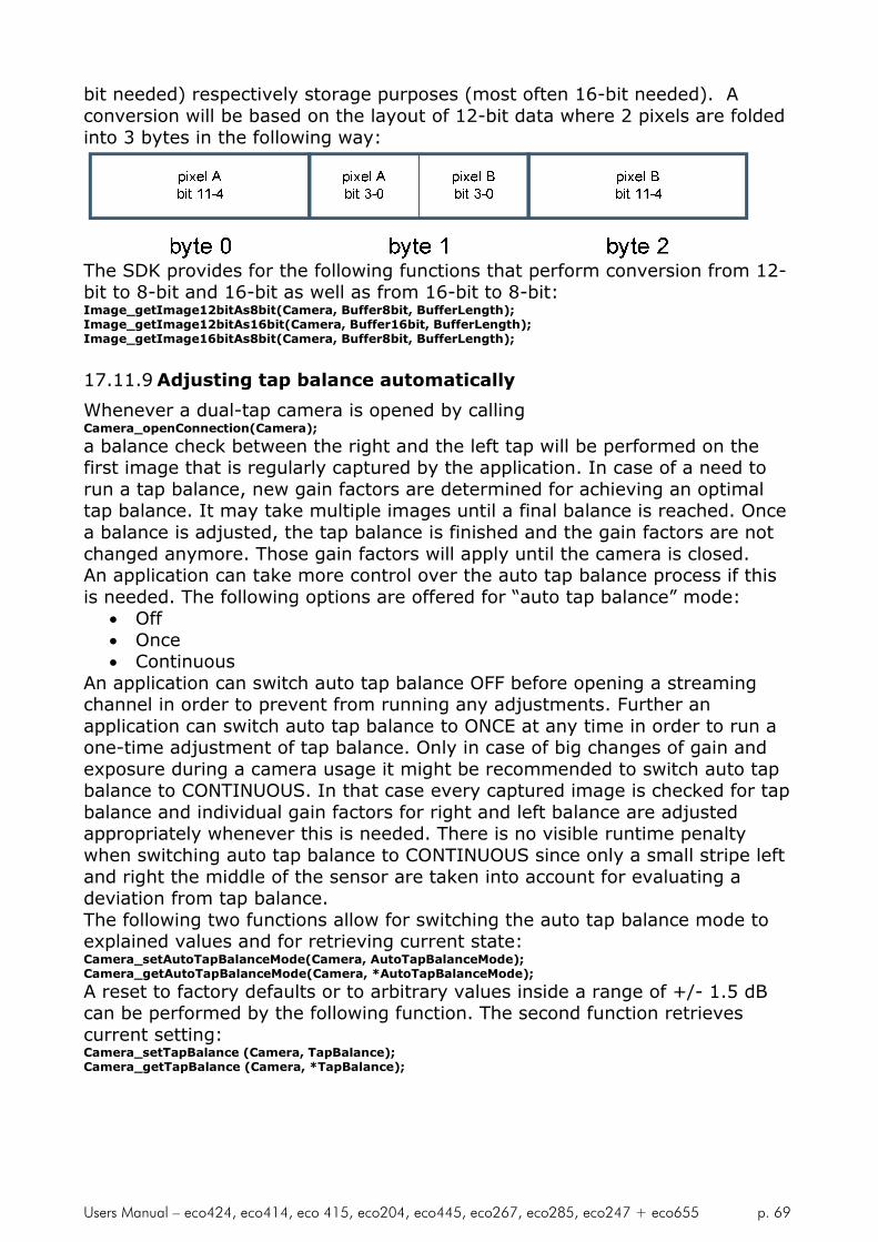
Users Manual – eco424, eco414, eco 415, eco204, eco445, eco267, eco285, eco247 + eco655 p. 69
bit needed) respectively storage purposes (most often 16-bit needed). Aconversion will be based on the layout of 12-bit data where 2 pixels are foldedinto 3 bytes in the following way:
The SDK provides for the following functions that perform conversion from 12-bit to 8-bit and 16-bit as well as from 16-bit to 8-bit:Image_getImage12bitAs8bit(Camera, Buffer8bit, BufferLength);Image_getImage12bitAs16bit(Camera, Buffer16bit, BufferLength);Image_getImage16bitAs8bit(Camera, Buffer8bit, BufferLength);
17.11.9 Adjusting tap balance automatically
Whenever a dual-tap camera is opened by callingCamera_openConnection(Camera);
a balance check between the right and the left tap will be performed on thefirst image that is regularly captured by the application. In case of a need torun a tap balance, new gain factors are determined for achieving an optimaltap balance. It may take multiple images until a final balance is reached. Oncea balance is adjusted, the tap balance is finished and the gain factors are notchanged anymore. Those gain factors will apply until the camera is closed.An application can take more control over the auto tap balance process if thisis needed. The following options are offered for “auto tap balance” mode:
Off Once Continuous
An application can switch auto tap balance OFF before opening a streamingchannel in order to prevent from running any adjustments. Further anapplication can switch auto tap balance to ONCE at any time in order to run aone-time adjustment of tap balance. Only in case of big changes of gain andexposure during a camera usage it might be recommended to switch auto tapbalance to CONTINUOUS. In that case every captured image is checked for tapbalance and individual gain factors for right and left balance are adjustedappropriately whenever this is needed. There is no visible runtime penaltywhen switching auto tap balance to CONTINUOUS since only a small stripe leftand right the middle of the sensor are taken into account for evaluating adeviation from tap balance.The following two functions allow for switching the auto tap balance mode toexplained values and for retrieving current state:Camera_setAutoTapBalanceMode(Camera, AutoTapBalanceMode);Camera_getAutoTapBalanceMode(Camera, *AutoTapBalanceMode);
A reset to factory defaults or to arbitrary values inside a range of +/- 1.5 dBcan be performed by the following function. The second function retrievescurrent setting:Camera_setTapBalance (Camera, TapBalance);Camera_getTapBalance (Camera, *TapBalance);

Users Manual – eco424, eco414, eco 415, eco204, eco445, eco267, eco285, eco247 + eco655 p. 70
17.11.10 Distributing image streams by multicast
The image stream of a GigE camera can be distributed to multiple PCs by usingthe multicast capabilities of current network hardware, in particular multicast-enabled switches. The following picture explains the basic principle:
A camera streams image data in a certain IP range (232.x.x.x) which has beendetermined for dynamic local host multicast allocation by the IANAorganisation (see http://www.iana.org/assignments/multicast-addresses formore details).A multicast-enabled switch is supposed to distribute the image stream to one,two or more applications. The advantage of having a switch distributing imagestreams is the optimal bandwidth usage between camera and switch as well asbetween switch and particular applications. There is no bandwidth wasted inthe described scenario.A multicast session consists of one controlling application and one or morelistening applications. Only the controlling application has write-access to thecamera. All other applications can only listen to the image stream that isinitiated and controlled by the controlling application.The connection between the controlling application and the camera isestablished as usual based on IP addresses. However, a switch has to bespecifically instructed for forwarding an image stream also to one or morelistening application. This is done by network packets which are sent out byapplications regularly all 60 seconds and which detection in a switch is knownas “IGMP snooping”.NOTE: A switch has to support “IGMP snooping” in order to establish asuccessful multicast session. Most often that feature is switched off innormal mode and has to be enabled by the web interface of a switch. Pleaserefer to instructions of a switch that is supposed to work in multicast mode.

Users Manual – eco424, eco414, eco 415, eco204, eco445, eco267, eco285, eco247 + eco655 p. 71
Programming interfaceWhen opening a camera, an application is supposed to check whether thecamera streams already in multicast mode using the function:Camera_getMulticastMode()
The multicast mode will be one of the following items: MULTICAST_MODE_NONE
MULTICAST_MODE_LISTENER
MULTICAST_MODE_CONTROLLER
If the camera is already streaming in multicast mode then the application canconnect to the camera but as listening application (MULTICAST_MODE_LISTENER).
Otherwise, if a camera is still idle (MULTICAST_MODE_NONE), an applicationcan request for a multicast session by switching a camera’s mode to“multicast” (MULTICAST_MODE_CONTROLLER) before opening the streamingchannel. The appropriate function is:
Camera_setMulticastMode()
Afterwards the application might check the automatically generated IP for themulticast group in the “232.x.x.x” range using the following function:Camera_getMulticastGroup()
Packet size considerationA controlling application will usually open a streaming channel at the highestavailable packet size, e.g. 16112 bytes. If another application connects to thatalready running streaming channel then a packet size problem may arise if thelistening application has not at least the packet size available that the imagestream is currently working with.Therefore a controlling application is supposed to limit the packet size of theimage data stream to a value which allows all intended listening applications toconnect to that image stream.If a listening application encounters a packet size problem, it will usuallyreceive the start and stop packages of each image since those are of smallsize. This causes a progress of image statistics like image counter, however,there will be no image data (image payload) available. The packet size has tobe reduced in this case by the controlling application in order to allow alllistening applications for receiving all image payload data properly.An application might choose to display a message to the user in the abovedescribed case like “Image payload missing. Multicast packet size too big? “ as it wasdone in the “SVGigE_Example.VC8” application in the SDK.
Users Manual – eco424, eco414, eco 415, eco204, eco445, eco267, eco285, eco247 + eco655 p. 72
17.11.11 Receiving messages asynchronously
An application can receive messages like e.g. “start of transfer”asynchronously in three different ways:
1. by registering an event callback
2. by using a blocking call when asking for new messages
3. by polling the event FIFO at arbitrary time
Before receiving any messages by event, an application will have to create anew event and then register one or multiple message types against that event.Afterwards, one of the above methods can be used for receiving events.
17.12 Adjusting IO configuration
SVS cameras have been equipped with a flexible IO interface includingstandard signals like TRIGGER and STROBE as well as common IO and UARTlines. The availability of particular signals is dependent on camera model. Forthe ECO-Line and HR-Line cameras the IO interface is available for freeconfiguration.The configuration of IO lines is based on a switching matrix as it is shownbelow.

Users Manual – eco424, eco414, eco 415, eco204, eco445, eco267, eco285, eco247 + eco655 p. 73
The above shown default assignment can be set by program as follows:
Camera_setIOAssignment(Camera,SVGigE_IOMux_OUT_IO_TXD,SVGigE_IOMux_IN_UART_OUT);Camera_setIOAssignment(Camera,SVGigE_IOMux_OUT_UART_IN,SVGigE_IOMux_IN_IO_RXD);Camera_setIOAssignment(Camera,SVGigE_IOMux_OUT_TRIGGER,SVGigE_IOMUX_IN1);Camera_setIOAssignment(Camera,SVGigE_IOMUX_OUT1,SVGigE_IOMux_IN_STROBE);
All not used outputs are usually not connected to any input. This is done asfollows:
Camera_setIOAssignment(Camera,SVGigE_IOMUX_OUT0,(SVGigE_IOMux_IN) 0);Camera_setIOAssignment(Camera,SVGigE_IOMUX_OUT2,(SVGigE_IOMux_IN) 0);Camera_setIOAssignment(Camera,SVGigE_IOMUX_OUT3,(SVGigE_IOMux_IN) 0);
Dependent on application requirements, above shown default configuration canbe changed arbitrarily by assigning other than the default inputs to an output.This involves in particular, that external input lines can also be put through toexternal output lines, e.g. for signal conversion purposes.
Fixed outputAn output line can also be driven to a determined value, Low or High.e.g. put a Low signal to OUT2:
Camera_setIOAssignment(Camera,SVGigE_IOMUX_OUT2, SVGigE_IOMux_IN_FIXED_LOW);
e.g. put a High signal to OUT2:Camera_setIOAssignment(Camera,SVGigE_IOMUX_OUT2, SVGigE_IOMux_IN_FIXED_HIGH);
Trigger simulation

Users Manual – eco424, eco414, eco 415, eco204, eco445, eco267, eco285, eco247 + eco655 p. 74
The ability to drive an output line to a determined value can also be used forsimulating a hardware trigger. From the camera operation point of view, this isalmost identical to releasing a trigger by an external hardware trigger signal.The only difference is that the electrical signal which triggers an imageacquisition will be generated inside the camera itself.The described trigger simulation can be done as follows:
Camera_setIOAssignment(Camera,SVGigE_IOMux_OUT_TRIGGER,SVGigE_IOMux_IN_FIXED_LOW);
Camera_setIOAssignment(Camera,SVGigE_IOMux_OUT_TRIGGER,SVGigE_IOMux_IN_FIXED_High);
The example applies to an active rising edge for releasing a trigger. Afterwardsone should not forget to connect the trigger with an appropriate externaltrigger line since otherwise external trigger signals would not have any effect:
Camera_setIOAssignment(Camera,SVGigE_IOMux_OUT_TRIGGER,SVGigE_IOMUX_IN1);
Input signalsIn addition to putting input signals through, e.g. for TRIGGER, their currentstate can also be determined by program as follows:IO_SIGNAL ProgrammedSignalValue;Camera_getIO(Camera, SVGigE_IOMUX_IN2, &ProgrammedSignalValue;
The above function call determines the current state of the IN2 signal line.Although the state of input signals can also be set by program, this is notrecommended. Instead, the fixed Low and High signals should be used in allcases where an output line has to be driven to a fixed value.
17.13 RS232 communication
Before starting RS232 communication, the UART’s parameters have to be adjusted appropriately.The following functions adjust and retrieve those settings:Camera_setUARTBaud(Camera_handle hCamera,SVGigE_BaudRate BaudRate);Camera_getUARTBaud(Camera_handle hCamera,SVGigE_BaudRate *ProgrammedBaudRate);
Subsequently, data can be sent and received over serial RS232 line using a block size of 512 bytes.If more than 512 bytes have to be sent or received, then those data will be transferred using thatblock size.Camera_setUARTBuffer(Camera_handle hCamera,unsigned char *Data,int DataLength);Camera_getUARTBuffer(Camera_handle hCamera,
unsigned char *Data,int *DataLengthReceived,int DataLengthMax,float Timeout);
NOTE: If DataLengthMax is set to less than the serial buffer size (512 bytes) and ifDataLengthMax is not sufficient for returning all buffered data then data loss will occur.
HINT: If more data will be transferred than the serial buffer size (512 bytes), then DataLengthMaxhas to match that serial buffer size. Only then a seamless transfer of data chunks can be performed,each chunk being the size of the serial buffer (512 bytes).

Users Manual – eco424, eco414, eco 415, eco204, eco445, eco267, eco285, eco247 + eco655 p. 75
Applying a LUT
SVS cameras may support a LUT, either 12-bit or 10-bit. They will be uploaded respectivelydownloaded to/from camera as an array of bytes using the following functions:Camera_setLookupTable(Camera_handle hCamera,
unsigned char *LookupTable,int LookupTableSize);
Camera_getLookupTable(Camera_handle hCamera,unsigned char *ProgrammedLookupTable,int LookupTableSize);
After uploading a LUT to the camera, the source pixel values from ADC will be translated to 8bitoutput values based on the LUT table as it is shown below.
255
40954094
18
17
16
12-bit input 8-bit output
255
1023
1022
6
5
4
10-bit input 8-bit output
7
1021
1020
Before uploading/downloading a LUT, a check needs to be performed what size of LUT issupported. The two values that need to be queried are:
CAMERA_FEATURE_LUT_12TO8
CAMERA_FEATURE_LUT_10TO8
Above values will be queried for by the following function:Camera_isCameraFeature(Camera_handle hCamera, CAMERA_FEATURE Feature);
If the function returns ‘true’ then it is save to use appropriate LUT size. Otherwise a trial forupload/download will fail.
A LUT can be enabled/disabled and the current mode can be retrieved by the following functions:Camera_setLookupTableMode(Camera_handle hCamera,
LUT_MODE LUTMode);Camera_getLookupTableMode(Camera_handle hCamera,
LUT_MODE *ProgrammedLUTMode);
There are functions provided that are implemented based of a LUT:
digital gain
digital offset

Users Manual – eco424, eco414, eco 415, eco204, eco445, eco267, eco285, eco247 + eco655 p. 76
gamma
The following functions allow for generating a LUT in order to control the above features:Camera_setGammaCorrection(Camera_handle Camera,
float GammaCorrection);Camera_setGammaCorrectionExt(Camera_handle Camera,
float GammaCorrection,float DigitalGain,float DigitalOffset);
First function will apply a ‘gamma’ in the range from 0.4 to 2.5 to all images and second functionwill additionally implement a digital gain and offset based on LUT.
SVGigE FilterDriver installation/de-installation
The SDK provides for functionality to install and to de-install a SVGigE FilterDriver:SVGigE_installFilterDriver(char *PathToDriverPackage,
char *FilenameINF,char *FilenameINF_m);
The 3 arguments will usually get a NULL pointer assigned. This provides to taking a default pathand default names of the INF files involved in driver installation.For de-installation the following function will be called:SVGigE_uninstallFilterDriver();
A SVGigE FilterDriver will be searched and subsequently de-installed from the system.

Users Manual – eco424, eco414, eco 415, eco204, eco445, eco267, eco285, eco247 + eco655 p. 77
18 Appendix D
Automated SVGigE Filter Driver installationSVCapture checks on start-up, whether a SVGigE filter driver is installed. If this is not the case thenthe user will be asked whether a filter driver should be installed automatically. An information isgiven that network connections will shortly be interrupted:
Alternatively, a FilterDriver installation can be started from menu:
The user will be informed about a short network interruption:
For both variants, the user will be asked for confirming warning dialogs:
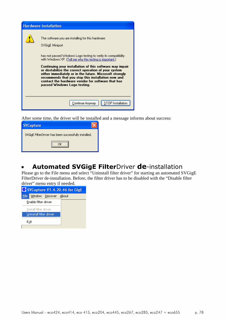
Users Manual – eco424, eco414, eco 415, eco204, eco445, eco267, eco285, eco247 + eco655 p. 78
After some time, the driver will be installed and a message informs about success:
Automated SVGigE FilterDriver de-installationPlease go to the File menu and select “Uninstall filter driver” for starting an automated SVGigEFilterDriver de-installation. Before, the filter driver has to be disabled with the “Disable filterdriver” menu entry if needed.
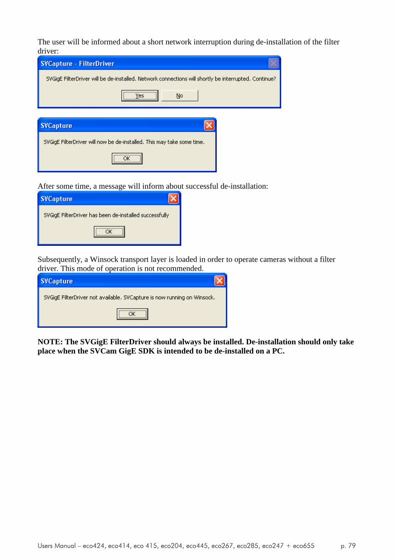
Users Manual – eco424, eco414, eco 415, eco204, eco445, eco267, eco285, eco247 + eco655 p. 79
The user will be informed about a short network interruption during de-installation of the filterdriver:
After some time, a message will inform about successful de-installation:
Subsequently, a Winsock transport layer is loaded in order to operate cameras without a filterdriver. This mode of operation is not recommended.
NOTE: The SVGigE FilterDriver should always be installed. De-installation should only takeplace when the SVCam GigE SDK is intended to be de-installed on a PC.

Users Manual – eco424, eco414, eco 415, eco204, eco445, eco267, eco285, eco247 + eco655 p. 80
Manual SVGigE FilterDriver installation
18.1 Installation Instruction for Filter Driver installation
In order to use the SVS GigE driver it has to be installed first. Thesetup will copy the driver to disk but will not install it. On astandard Windows XP/2000 system this has to be done by the following steps:
IMPORTANT: Usually the driver will be copied by the setupprocedure to the following location:
C:\Program Files\SVS-VISTEK GmbH\SVS GigE SDK 1.2.1\SVS GigE FilterDriver
Step-by-step
Step 1: Open the Network Connections dialog

Users Manual – eco424, eco414, eco 415, eco204, eco445, eco267, eco285, eco247 + eco655 p. 81
Step 2: Open the Properties dialog for LAN connections and click on “Install…”
Step 3: In the “Select Network Component Type” dialog select the Serviceoption and click on “Add…”

Users Manual – eco424, eco414, eco 415, eco204, eco445, eco267, eco285, eco247 + eco655 p. 82
Step 4: In the “Select Network Service” dialog click on “Have Disk…”
Step 5: *In the “Install From Disk” dialog the folder where the driver
files are located needs to be navigated to or entered directly into thefiles field.*

Users Manual – eco424, eco414, eco 415, eco204, eco445, eco267, eco285, eco247 + eco655 p. 83
Step 6: After clicking on OK the “Select Network Service” dialog will display amessage that the driver is not digitally signed. Click on OK.
Step 7: Because the driver not being digitally signed, a dialog will appear witha warning. Answer with “Continue Anyway” as often as needed.

Users Manual – eco424, eco414, eco 415, eco204, eco445, eco267, eco285, eco247 + eco655 p. 84
Step 8: After confirming the prior dialogs the driver is installed and shouldshow up as a new item in the “LAN Connections Properties” dialog.

Users Manual – eco424, eco414, eco 415, eco204, eco445, eco267, eco285, eco247 + eco655 p. 85
Step 9: The dialog can be closed and the “GigE Vision Driver SVS-VISTEKGmbH” is ready for use.
The main dialog in SVCapture will show an extension “FilterDriver” whichindicates that the driver will be used next time when opening a camera. If thisextension is not shown it can be activated in the “File | Enable filter driver”menu item.
Step 10: Follow point 5 “Displaying Live Images” in this documentation forstarting an image view. If the driver was successfully installed and worksproperly the externsion “FilterDriver” will remain in the main dialog’s caption.Otherwise it will disappear and the SVCapture program falls back to operatingthe GigE Vision camera over WinSock.
Users Manual – eco424, eco414, eco 415, eco204, eco445, eco267, eco285, eco247 + eco655 p. 86
19 Appendix E
19.1 PC and OS Requirements
It is recommended to use a PC with a Pentium P4 processor at 2.4 GHz orhigher. The camera is working also on lower frequencies but it might notdeliver the full frame rate in those cases. The operation system must be XP orWin 7. We don’t support WIN 98/ NT/2000 or older Operation systems. ALinux driver is available, too. For VXworks a source code for driverdevelopment can be offered on request. Interfacinging must be developed bythe experienced user.
19.2 Firewall considerations
The GigE Vision standard defines a communication based on UDP packetsbetween a GigE Vision compliant camera and a host PC. Often PC firewalls areadjusted to be restrictive and not to allow for sending UPD packets from theoutside of the PC to a port that has been opened by an application
Sometimes the firewall settings have been adjusted during installation of theoperating system or afterwards such that the user will be asked if the UDPdata stream should be enabled once a camera starts sending UDP packets tothe PC. When clicking OK in response to that question the application will beadded to a list of exceptions. A firewall will let those applications communicatewith network devices like a GigE Vision camera over the network. In case theWindows installation has been adjusted such that the user will not be askedwhen an outside device starts sending network packets to an application thenthat application has to be enabled manually in order to achieve the same asbefore.An appropriate dialog can be opened for example when right-clicking onthe network icon in the tray and selecting “Change Windows.
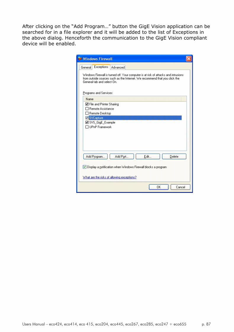
Users Manual – eco424, eco414, eco 415, eco204, eco445, eco267, eco285, eco247 + eco655 p. 87
After clicking on the “Add Program…” button the GigE Vision application can besearched for in a file explorer and it will be added to the list of Exceptions inthe above dialog. Henceforth the communication to the GigE Vision compliantdevice will be enabled.

Users Manual – eco424, eco414, eco 415, eco204, eco445, eco267, eco285, eco247 + eco655 p. 88
20 Appendix F
20.1 Firmware-Update with “GigE Update Tool.exe“ program
Note: In order to work with the latest driver and SVCapture it might benecessary to UPDATE the firmware inside the camera. This can be done in thefield. It is usually not necessary to send the camera in.
Warnings:
Camera must have power
Camera must be access able from PC via network
Camera SHOULD NOT be used during programming procedure
Camera SHOULD NOT be disconnected during programming procedureor be disconnected from network
Programming software SHOULD NOT be stopped during procedure.
It might take up to some minutes until it is completed.
Step1: Locate „svgigeup.exe“ using Windows Explorer

Users Manual – eco424, eco414, eco 415, eco204, eco445, eco267, eco285, eco247 + eco655 p. 89
Step 2 Execute svgigeup.exe
Step 3 Select Camera (e.g. 1 and press Enter)
Step 4: Wait and follow
instructions
YOU ARE DONE
After programming it is recommended to start the camera again. This meansyou have to disconnect power and – after some seconds – power up again.
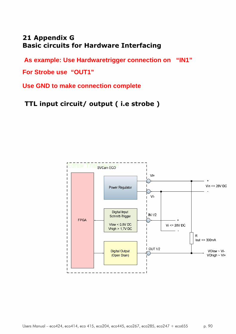
Users Manual – eco424, eco414, eco 415, eco204, eco445, eco267, eco285, eco247 + eco655 p. 90
21 Appendix GBasic circuits for Hardware Interfacing
As example: Use Hardwaretrigger connection on “IN1”
For Strobe use “OUT1”
Use GND to make connection complete
TTL input circuit/ output ( i.e strobe )

Users Manual – eco424, eco414, eco 415, eco204, eco445, eco267, eco285, eco247 + eco655 p. 91
22 Appendix H Safety Instructions
In order to avoid personal injuries, or property damages againsthim/her or people around him/her by using this product correctly.
Prior to use, read this section carefully to fully understand itsinstructions for correct use.
22.1 Definition of markings
The meaning of each mark used in this instruction manual is given below
DANGER This mark warns the user that improper use, indicated with thismark, may cause death or severe personal injuries against theuser or people around him/her.
CAUTION This mark warns the user that improper use, indicated with thismark, may cause personal injuries (*1) or material damages (*2)against the user or people around him/her.
Notes*1: Personal injuries meanwounds, burns, electric shocks,and others for which the personinjured need neither to behospitalized nor to be cared forthe long term*2: Material damages meanany direct or consequentialdamages related to property ormaterial loss
This mark indicates what the user SHOULD NOT DO. Thedetails of things, which the user should not do, are describednext to this mark.
This mark indicates what the user MUST DO. The details ofthings, which the user must do, are described next to thismark.
This mark indicates that the user must be alert against apossible DANGER. The details of the DANGER, which the usermust be aware of are described next to this mark.
This mark indicates that the user is given a CAUTION againstpossible hazards. The details of the CAUTION, which the usermust be aware of, are described next to this mark.
Handling Precautions

Users Manual – eco424, eco414, eco 415, eco204, eco445, eco267, eco285, eco247 + eco655 p. 92
DANGERIf any overheating sign is observed, discontinue the useimmediately.In the event that smoke, smell, or any other overheatingsign is observed, turn the power switch of the system OFFimmediately and remove the power cable(s) from thesystem connectors, like computer, camera, lightning. DoNOT try to continue to use the system. To do so in spite ofclear signs of malfunction invites a fire, an electric shockhazard, or a serious damage to the system components. Insuch case, contact for repair service us or ourdealer/distributor, from which you purchased the system.
If any malfunctioning sign is observed, discontinue the useimmediately.Do NOT try to use the system when it is malfunctioning.(Ex. No images on the monitor) In the event of malfunction,turn the power switch of the system OFF immediately andremove the system power cables from the systemcomponents connectors. In such case, contact for repairservice us or our dealer/distributor from which youpurchased the system.
If any foreign object gets into the system components,discontinue the use immediately.In the event that liquids, small particles, or any otherforeign objects get into the system components, do NOT tryto continue to use the system. To do so invites a fire or anelectric shock hazard. In that case, turn the power switch ofthe system components OFF immediately and remove thesystem power cables from the system componentsconnectors. After that, contact us or our dealer/distributorfrom which you purchased the camera for repairservice/technical advice.
Do NOT disassemble the system components.Do NOT attempt to pull apart; repair, or modify the systemcomponents on your own. To do so leads to a fire or anelectric shock accident. Contact us or the dealer/distributorfrom which you purchased the camera forrepair/modifacation.
Do NOT supply any power than specified.The system components are designed to work only underspecified voltage. Do NOT attempt to drive the systemcomponents with the power other than specified. Operatingthe system components under power other than specifiedinvites a fire or a electric shock hazard.
Do NOT use the system components in a high-humidityenvironment.

Users Manual – eco424, eco414, eco 415, eco204, eco445, eco267, eco285, eco247 + eco655 p. 93
Do NOT place the system components near a humidifier, orin other high-humidity environment. To do so may cause afire or an electric shock accident.
CAUTION
If the system components are operated in theelectromagnetic field, there may be cases where noises(vertical, horizontal, or oblique stripes) may appear to avideo output or causes other malfunctions. In that case,take preventive measures on the electromagnetic-wavegenerating source so that the system components do notreceive the interference by the electromagnetic- wave. Takeextra precautions against electromagnetic-wave-interference if the system components are used with aservomotor, inverter, or other electromagnetic-wave-generating equipment.
Avoid giving a strong shock against the systemcomponents. If your system components are used in thesystem where the connector are subjected to strongrepetitive shocks, the connector are possible to break down.If you intend to use your system components in such asituation, make sure to use an optional-connector-fixing-hardware to connect the connector-plug to the systemcomponents body.When the system components are not in use, put a lens ora lens-cap onto the cam head so that the image pickupplane of CCD is protected from dust, foreign object, or otherflaw-causing object. If the glass plane (image pickup plane)gets dirty, clean it with a cotton swab. When it needs to becleaned with a cleaner, be sure NOT to use any organicsolvent other than ethyl alcohol. Do not clean the othersystem components. In such a case call us or thedealer/distributor from which you purchased the systemcomponents for cleaning or cleaning instructions.As a countermeasure against condensation, when thesystem components are moved from a warm place to a coldplace, take appropriate precautions to prevent condensationfrom forming on the system components.
Do not pull strongly the any cable nor swing it. The stressfrom pulling or swinging may cause damage in the coatingof the cable, or breaks in the inside wires.
Avoid short-circuiting its signal output. Otherwise, thesystem components might be damaged.
If too much amount of light, (= the incoming light amountof 100 times or greater in comparison with standard light)enters CCD image pickup plane, video output might not beobtained. In such a case, take measures to reduce theamount of incoming light.
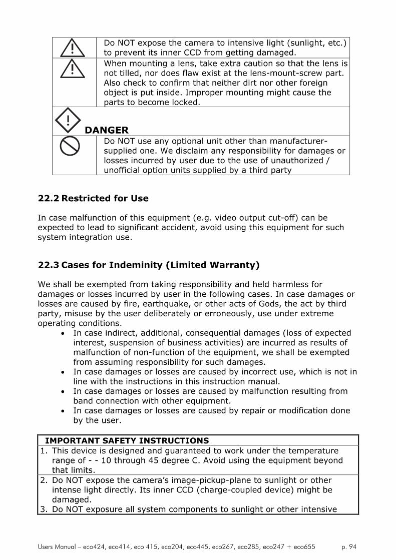
Users Manual – eco424, eco414, eco 415, eco204, eco445, eco267, eco285, eco247 + eco655 p. 94
Do NOT expose the camera to intensive light (sunlight, etc.)to prevent its inner CCD from getting damaged.
When mounting a lens, take extra caution so that the lens isnot tilled, nor does flaw exist at the lens-mount-screw part.Also check to confirm that neither dirt nor other foreignobject is put inside. Improper mounting might cause theparts to become locked.
DANGERDo NOT use any optional unit other than manufacturer-supplied one. We disclaim any responsibility for damages orlosses incurred by user due to the use of unauthorized /unofficial option units supplied by a third party
22.2 Restricted for Use
In case malfunction of this equipment (e.g. video output cut-off) can beexpected to lead to significant accident, avoid using this equipment for suchsystem integration use.
22.3 Cases for Indeminity (Limited Warranty)
We shall be exempted from taking responsibility and held harmless fordamages or losses incurred by user in the following cases. In case damages orlosses are caused by fire, earthquake, or other acts of Gods, the act by thirdparty, misuse by the user deliberately or erroneously, use under extremeoperating conditions.
In case indirect, additional, consequential damages (loss of expectedinterest, suspension of business activities) are incurred as results ofmalfunction of non-function of the equipment, we shall be exemptedfrom assuming responsibility for such damages.
In case damages or losses are caused by incorrect use, which is not inline with the instructions in this instruction manual.
In case damages or losses are caused by malfunction resulting fromband connection with other equipment.
In case damages or losses are caused by repair or modification doneby the user.
IMPORTANT SAFETY INSTRUCTIONS1. This device is designed and guaranteed to work under the temperature
range of - - 10 through 45 degree C. Avoid using the equipment beyondthat limits.
2. Do NOT expose the camera’s image-pickup-plane to sunlight or otherintense light directly. Its inner CCD (charge-coupled device) might bedamaged.
3. Do NOT exposure all system components to sunlight or other intensive

Users Manual – eco424, eco414, eco 415, eco204, eco445, eco267, eco285, eco247 + eco655 p. 95
light (UV, IR).4. In the event that any abnormal condition is observed, turn the power
switch OFF immediately. Do NOT try to continue to use the systemcomponents. To do so in spite of clear signs of malfunction invites a fire,an electric shock hazard, or any other serious damage to the systemcomponents. In such case, contact us or our dealer/distributor that youpurchased the system components from for repair service.
5. To clean the body of this equipment, make sure to turn all power switchesOFF first. To remove stubborn stains, use a soft cloth soaked in dilutedacid free detergent. After that, clean with a dry cloth.
6. In case the image-pickup-plane should be settled with fine dust, dirt, orscratched, ask our distributor for technical advice


