BETA Microphones Brochure (English).… · Beta ® ® ® ® ® ® ® ® ® ® ® ® ® ®

Users GuideWyse® Winterm™ 3 series,Based on Microsoft® Windows® CE
Issue: 121906PN: 883630-07 Rev. C

Copyright Notices© 2006, Wyse Technology Inc. All rights reserved.
This manual and the software and firmware described in it are copyrighted. You may not reproduce, transmit, transcribe, store in a retrieval system, or translate into any language or computer language, in any form or by any means, electronic, mechanical, magnetic, optical, chemical, manual or otherwise, any part of this publication without express written permission.
End User License Agreement (“License”)A copy of the Wyse Technology End User License Agreement is included in the software and provided for your reference only. The License at http://www.wyse.com/license as of the purchase date is the controlling licensing agreement. By copying, using, or installing the software or the product, you agree to be bound by those terms.
TrademarksWyse and Winterm are registered trademarks, and the Wyse logo and Winterm logo are trademarks of Wyse Technology Inc. ICA is a registered trademark and MetaFrame is a trademark of Citrix Systems Inc. Microsoft and Windows are registered trademarks of Microsoft Corporation. All other products are trademarks and/or registered trademarks of their respective companies. Specifications subject to change without notice.
PatentsThis product and/or associated software are protected by copyright, international treaties, and various patents, including the following U.S. patents: 6,836,885 and 5,918,039.
Restricted Rights LegendYou acknowledge that the Software is of U.S. origin. You agree to comply with all applicable international and national laws that apply to the Software, including the U.S. Export Administration Regulations, as well as end-user, end-use and country destination restrictions issued by U.S. and other governments. For additional information on exporting the Software, see http://www.microsoft.com/exporting.
Ordering InformationFor availability, pricing, and ordering information in the United States and Canada, call 1-800-GET-WYSE (1-800-438-9973) or visit us at http://www.wyse.com. In all other countries, contact your sales representative.
FCC StatementThis equipment has been tested and found to comply with the limits for either Class A or Class B digital devices (refer to “Thin Client Requirements Compliance”), pursuant to Part 15 of the FCC Rules. These limits are designed to provide reasonable protection against harmful interference in a residential installation. This equipment generates, uses, and can radiate radio frequency energy and, if not installed and used in accordance with the instructions, may cause harmful interference to radio communications. However, there is no guarantee that interference will not occur in a particular installation. If this equipment does cause harmful interference to radio or television reception, which can be determined by turning the equipment off and on, the user is encouraged to try to correct the interference by one or more of the following measures:• Reorient or relocate the receiving antenna.• Increase the separation between the equipment and the receiver.• Connect the equipment into an outlet on a circuit different from that to which the receiver is connected.• Consult the dealer or an experienced radio/TV technician for help.
CautionChanges or modifications not covered in this manual must be approved in writing by the manufacturer’s Regulatory Engineering department. Changes or modifications made without written approval may void the user’s authority to operate the equipment.

Regulatory Compliance for Thin Clients
EMC and Safety RequirementsModels x150SE, SX0, and VX0 thin clients are compliant with the regulatory requirements in the regions listed below.
U.S.A. - FCC Part 15 (class B), UL60950 Canada - ICES-003, CAN/CSA-C22 No. 60950Europe - EN 55022 (class B), EN 61000-3-2 (class A), EN 61000-3-3, EN 55024, EN 90650-1:2000+ALLAustralia / New Zealand - AS/NZS CISPR 22Japan - VCCI CISPR 22 (class B)China - CCC GB9254-1998, GB17625.1-2003, GB 4943-2001Korea - MIC
RF & EMC RequirementsModel VX0 thin clients with internal wireless option are compliant with the regulatory standards in the regions listed below.
U.S.A. - FCC Part 15 C, 15.401-15.407, FCC 1.1310 (RF exposure)Canada - RSS-210Europe - EN 55022 (class B), EN300.328, EN301.489-1, EN301.489-17 Australia / New Zealand - AS/NZS 4771Japan - Telec (Equipment Radio Regulation, 2006)China - SRRC (CMII)Korea - MIC (RRL)
Canadian DOC NoticesClass A - This digital apparatus does not exceed the Class A limits for radio noise emissions from digital apparatus set out in the Radio Interference Regulations of the Canadian Department of Communications.Le présent appareil numérique n’émet pas de bruits radioélectriques dépassant les limites applicables aux appareils numériques de la classe A prescrites dans le Réglement sur le brouillage radioélectrique édicté par le Ministère des Communications du Canada.
Class B - This digital apparatus does not exceed the Class B limits for radio noise emissions from digital apparatus set out in the Radio Interference Regulations of the Canadian Department of Communications.Le présent appareil numérique n’émet pas de bruits radioélectriques dépassant les limites applicables aux appareils numériques de la classe B prescrites dans le Réglement sur le brouillage radioélectrique édicté par le Ministère des Communications du Canada.
Wireless Usage and RequirementsRadio transmitting type devices (RF module) are present in the Model VX0 as an option. These devices operate in the 2.4 GHz band (i.e. 802.11b/g WLAN & Bluetooth).
As a general guideline, a separation of 20 cm (8 inches) between the wireless device and the body, for use of a wireless device near the body (this does not include extremities) is typical. This device should be used more than 20 cm (8 inches) from the body when wireless devices are on and transmitting.
Some circumstances require restrictions on wireless devices. Examples of common restrictions include:• When in environments where you are uncertain of the sanction to use wireless devices, ask the applicable
authority for authorization prior to use or turning on the wireless device.• Every country has different restrictions on the use of wireless devices. Since your system is equipped with a
wireless device, when traveling between countries with your system, check with the local Radio Approval authorities prior to any move or trip for any restrictions on the use of a wireless device in the destination country.
• Wireless devices are not user-serviceable. Do not modify them in any way. Modification to a wireless device will void the authorization to use it. Please contact the manufacturer for service.
Cable NoticeThe use of shielded I/O cables is required when connecting this equipment to any and all optional peripheral or host devices. Failure to do so may cause interference and violate FCC and international regulations for electromagnetic interference.

Noise Suppressor for Model x150SEA noise suppressor (ferrite bead) must be installed on the network cable of your thin client. This installation is necessary to maintain compliance with U.S. FCC B limits and European CISPR B EN55022 Class B limits. The noise suppressor is supplied by the manufacturer and is packed in your thin client shipping carton.
Device Power SupplyFor use with external power supply included in the shipping carton, or a certified equivalent model supplied by the manufacturer.
Model x150SE Thin Clients For use with External Power Supply DVE Model DSA-0421S-12 3 30, or certified equivalent model supplied by the manufacturer, rated 12Vdc, 2.5A.
Model SX0 Thin Clients For use with External Power Supply DVE Model DSA-0421S-12 3 30, or certified equivalent model supplied by the manufacturer, rated 12Vdc, 2.5A.
Model VX0 Thin Clients For Use with External Power Supply Model LSE9802A1255, or UL Listed Power Unit marked "Class 2" or "LPS" and rated for minimum 12 Vdc, 4.0A.
Battery Information: The VX0 Thin Client contains a battery replaceable by qualified service personnel only.
WarningThere is a risk of explosion if the battery is replaced by an incorrect type. Always dispose of used batteries according to the instructions accompanying the battery.

Contents
1 Introduction 1About this Guide 1
Organization of this Guide 1Wyse Technical Support 1
Related Online Resources Available at Wyse 2
2 Getting Started 3What Happens When You Turn on Your Thin Client 3
Accessing the Enterprise Servers Available 5Logging-In 6
Changing Your Password 6Knowing Your Assigned Privileges 6About the Session Services You Will Use 7
Logging-Out and Shutting Down 7Using the Desktop 8
Understanding the Taskbar Features 9Using the Connection Manager 10
3 Setting-up the Thin Client 13Using the Control Panel Applications 13
Setting the Date and Time 14Selecting Display Settings 15Setting Keyboard Properties 16Configuring Line Printer Daemon (LPD) Services 18
Creating a New LPD Configuration 18Editing an LPD Configuration 20Deleting an LPD Configuration 21
Configuring LPR Settings 22Configuring Modems 24Setting Mouse Properties 25Configuring Network Adapters 26Configuring the Optional Internal Wireless Feature 27Synchronizing Thin Client Time with SNTP Client 33Using the System Information Features 34Setting Volume Properties 35
Modifying PNAgent Settings on the Thin Client 36
Figures 37
Tables 39

vi Contents
This page intentionally blank.

1 Introduction
Wyse® WintermTM 3 series Thin Clients use the Windows™ CE operating system. These thin clients provide a local browser and access to applications, files, and network resources made available on machines hosting Citrix™ ICA and Microsoft™ RDP session services. Thin client emulation software is installed locally by default. Other locally installed software permits remote administration of the thin clients and provides local maintenance functions. Additional Add-ons are available that support a wide range of peripherals and features for environments needing a secure Windows user interface.
Session and network services available on enterprise networks may be accessed through a direct Intranet connection, a dial-up server, or an ISP which provides access to the Internet and thus permits the thin client to connect to an enterprise VPN (virtual private network) server.
NoteFor information about each of the connection types available on the thin client, refer to "Using the Connection Manager."
About this GuideThis guide is intended for users of the Wyse® WintermTM 3 series Thin Client. It provides detailed instructions on using the thin client to manage the connections and applications available to users from a network server.
Organization of this GuideThis guide is organized as follows:
Chapter 2, "Getting Started," provides information to help you quickly get started using your thin client. It describes basic thin client functions and provides instructions on using the Desktop and Connection Manger to manage the connections and applications available for you to use.
Chapter 3, "Setting-up the Thin Client," contains information to help you set up your thin client using the applications available in the Control Panel.
Wyse Technical SupportTo access Wyse technical resources, visit http://www.wyse.com/serviceandsupport. If you still have questions, you can submit your questions using the Wyse Support Help Form, or call Customer Support at 1-800-800-WYSE (toll free in U.S. and Canada). Hours of operation are from 5:00 am to 5:00 pm PST, Monday through Friday.
To access international support, visit http://www.wyse.com/global.

2 Chapter 1
Related Online Resources Available at WyseWyse® WintermTM 3 series Thin Client features can found in the Datasheet for your specific thin client model. Datasheets are available on the Wyse Web site at:http://http://www.wyse.com/products.
If you need to upgrade your CE .NET operating system, contact Wyse Customer Support at: http://www.wyse.com/serviceandsupport.
The Administrators Guide: Wyse® WintermTM 3 series, Based on Microsoft® Windows® CE is intended for administrators of the Wyse® WintermTM 3 series Thin Client. It provides information and detailed system configurations to help administrators design and manage a Wyse® WintermTM 3 series Thin Client environment. It is available at:http://www.wyse.com/manuals.
The Add-on Administrators Guide: Wyse® WintermTM 3 series, Based on Microsoft® Windows® CE is intended for administrators of the Wyse® WintermTM 3 series Thin Client. It provides instructions on preparing for installing the Add-ons as well as obtaining and verifying the Add-ons for the Wyse® WintermTM 3 series Thin Client. It also provides detailed procedures for installing and removing the Add-ons. In addition, this guide provides the Add-ons for Wyse® WintermTM 3 series Thin Client ReadMe documentation. It is available at: http://www.wyse.com/manuals.
The Local Smart Card Administrators Guide: Wyse® WintermTM 3 series, Based on Microsoft® Windows® CE is intended for administrators of the Wyse® WintermTM 3 series Thin Client. It provides instructions on preparing to install the Local Smart Card Add-on as well as instructions on obtaining and verifying the Add-on. It also provides detailed procedures for installing, removing, and using the Add-on. It is available at:http://www.wyse.com/manuals.
2 Getting Started
This chapter provides information to help you quickly get started using your thin client. It describes basic thin client functions and provides instructions on using the Desktop and Connection Manger to manage the connections and applications available for you to use.
What Happens When You Turn on Your Thin ClientWhat you see, initially, when you turn on or reboot your thin client, depends on your method of access to the enterprise intranet and how your network administrator has set up your account. With Wyse CE software, your thin client can also be turned on by the Wake-On-LAN feature. Using this feature, an administrator can turn on the thin client connection remotely.
A username and password may be required to log in to your thin client or the thin client may automatically log in when started. After logging on, you may see the Desktop, as described in "Using the Desktop," or the Connection Manager, as described in "Using the Connection Manager" (or if configured, an application or connection may be launched automatically).
NoteIf the thin client is configured to obtain an IP address from a DHCP server (this is the default for a new or reset thin client), a message is displayed indicating that the thin client is waiting for network services. If the thin client is unable to obtain an IP address, a message is displayed suggesting that an IP address be statically assigned. In such a case, have your administrator perform this task.
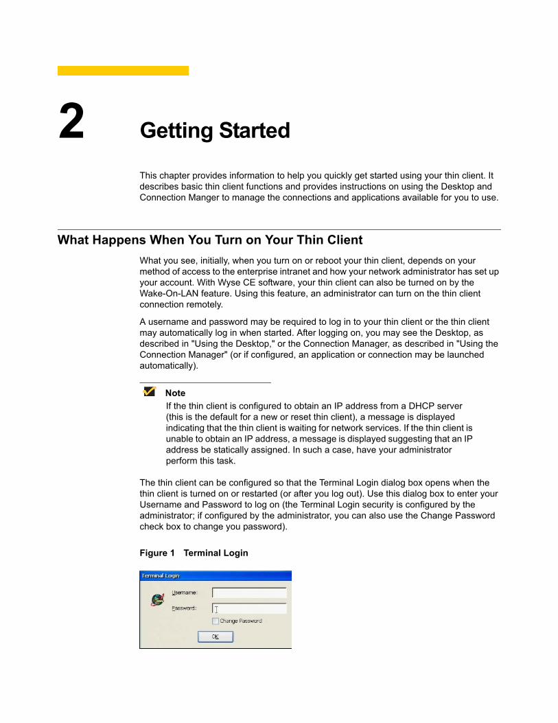
The thin client can be configured so that the Terminal Login dialog box opens when the thin client is turned on or restarted (or after you log out). Use this dialog box to enter your Username and Password to log on (the Terminal Login security is configured by the administrator; if configured by the administrator, you can also use the Change Password check box to change you password).
Figure 1 Terminal Login
4 Chapter 2
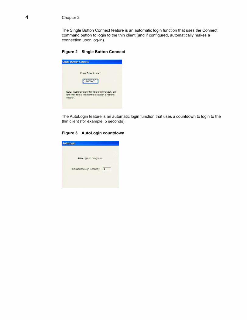
The Single Button Connect feature is an automatic login function that uses the Connect command button to login to the thin client (and if configured, automatically makes a connection upon log-in).
Figure 2 Single Button Connect
The AutoLogin feature is an automatic login function that uses a countdown to login to the thin client (for example, 5 seconds).
Figure 3 AutoLogin countdown

Getting Started 5
Accessing the Enterprise Servers AvailableThere are five basic methods of access to the enterprise server environment available to the thin client. Except for Ethernet Direct, all of the access methods require that some local settings be made on the thin client. For certain privileges, these local settings are retained and are available for the next thin client system start. Activating these local settings and the defined connections can also be automated at thin client system start.
Methods of access include:• Ethernet Direct - This is a connection from the thin client Ethernet port directly to the
enterprise intranet. No additional hardware is required. An account sign-on dialog box displays if required. In this configuration all network services may be used, including the enterprise DHCP server. A DHCP server on the network may provide not only the thin client IP address, but also the location of the file server containing the software updates.
• Wireless Direct - If a wireless network device is connected to and configured on the thin client, and a wireless a connection is established, the behavior is the same as for an Ethernet Direct connection.
• PPPoE - Point-to-Point Protocol over Ethernet (PPPoE) is available for use. The PPPoE Connection Wizard is available from the Connection Manager to configure and invoke a PPPoE connection to WAN. Once connected, all WAN packets go though a PPP connection over Ethernet to the modem.
• Dialup Modem - A dial-up modem can be used with the thin client to access a dial-up server. The dial-up server must be a Microsoft Remote Access Server or another server that supports industry-standard protocols. The dial-up server can provide either of the following methods of access to the enterprise intranet:• Direct access - An enterprise dial-up server directly connects to the enterprise
intranet.• Indirect access - An Internet Service Provider (ISP) dial-up server simply provides
access to the Internet, from which the thin client accesses an enterprise PPTP VPN server that connects to the enterprise intranet.
• VPN (PPTP) - Point-to-Point Tunneling Protocol (PPTP) is a network protocol that enables the secure transfer of data between a remote client (in this case the thin client) and an enterprise server environment by creating a Virtual Private Network (VPN) across TCP/IP-based data networks such as the Internet. It provides a password-protected path through the enterprise firewall to the enterprise server environment in which the network and session services required by thin clients reside. An Internet Service Provider (ISP) must be available to provide access to the Internet. Any of the standard means of connecting to the ISP may be used, such as a dial-up modem, cable modem, or DSL modem.
NoteThe connection to the ISP must be established before contacting the enterprise VPN (PPTP) server (this includes dial-up access, as well as direct access through cable modem and DSL modem paths).

6 Chapter 2
Logging-InAfter a connection to the enterprise intranet is established, login to the network and/or session services may or may not be required (depending on configurations set by the network administrator, the session servers, or any other requirements). If login to the enterprise intranet is required, a Terminal Login dialog box opens when you turn on the thin client, when you restart the thin client, or after logging off from a user account.
Username and password are assigned initially by the administrator when the account is established, but the password can be changed by the user at a thin client (see "Changing Your Password"). To login to a standard account, enter the username for the account and password allocated to you by the network administrator. Account usernames are not case sensitive, however, passwords are case sensitive.
NoteIf you cannot successfully login, ask your network administrator for help.
Changing Your PasswordIf you are required to log in, you can change your assigned password by selecting the Check here to change password check box in the Terminal Login dialog box and using the change password dialog box (type the new password in both the New Password and Confirm boxes, and click OK).
Knowing Your Assigned PrivilegesAs a thin client operator, you have a thin client account with certain privileges. Your thin client account is a set of application connection definitions and thin client configuration settings that are grouped under a privilege level and assigned to you by your administrator. Administrators create thin client accounts that possess specific connection capabilities, security, and various thin client functions. Assigned privileges allow you certain levels of access to thin client resources.
The three types of operator privilege levels are:• Administrator - With an Administrator privilege level, you can use all of the functions
of the thin client. For example, you can add, modify, and delete accounts, and configure or re-configure the connections available for any account.
• User - With a User privilege level, you can access and use a limited number of thin client functions (as determined by the administrator).
• Guest - With a Guest privilege level, you can access and use the fewest number of thin client functions (as configured by the administrator).

Getting Started 7
About the Session Services You Will UseThe Desktop connection icons and Connection Manager list entries allow you to initiate connections to servers providing ICA, RDP, terminal emulation, and other services. These services are configured by the administrator for you to use. You can start connections by using the various Desktop or the Connection Manager options made available by the administrator.
The Multiple Sessions feature allows the thin client to have multiple active connections. The number of active connections you can have depends on the following:• amount of RAM• types of connections open• number of connections configured
NoteIf your administrator has enabled Support launching multiple instances on new Desktop with the New Desktop option, you can also open multiple instances of one ICA or RDP connection (supported for published applications configured as Seamless Windows Connection or PNAgent enabled sessions).
Logging-Out and Shutting DownAfter using your thin client, you can sign off from your account (if you signed in initially) or you can shut down the thin client (if your privilege allows).
Clicking Start | Shut Down on the windows desktop or clicking Shut Down in the Connection Manager opens the Shutdown Window. Use this window to select the Logout, Shutdown the terminal, or Shutdown and Restart option you want. Logging out is available to all operator privilege levels (Guest, User, and Administrator), if local terminal security is enabled.
NoteIf an automatic login function is enabled and you log out or restart, the thin client will automatically login.
Figure 4 Shutdown Window
NoteDepending on how the servers and applications are configured, logging-off from or shutting down the thin client may not necessarily close the open server sessions. Generally, you should close sessions before logging-off from or shutting down the thin client.

8 Chapter 2
Using the DesktopA windows interface option (New Desktop) is provided that includes connections, applications, icons, a taskbar, a Start menu, and several related features. It allows you to easily make connections and use the various applications and features made available to your account by your administrator.
Figure 5 Desktop - User example
NoteThe Start menu allows quick and easy access to all programs and settings made available by your administrator, as well as shutting down the thin client.
Use the following guidelines:• To start connections, double-click a desktop icon, right-click on a desktop icon and
select Open, or use the Start menu (menu options depend on administrator configurations).
• To open the Control Panel, click Start | Settings | Control Panel. To start an application in the Control Panel, double-click the application icon.
• Desktop icons can easily be arranged by right-clicking on the desktop and using the menu provided.
• You can toggle between active connections using the taskbar (click on an open connection) or by using the Alt+Tab key combination (for details on these and other taskbar features, refer to "Understanding the Taskbar Features").
• Seamless integration of local and remote applications on the local desktop is supported. Within a single session, you can access multiple applications and switch between local and remote applications. In seamless windows mode, applications running on the server appear to the thin client as if they are running locally, and each application appears in its own re-sizable window. This feature is only available for published applications, and if configured by the administrator.

Getting Started 9
Understanding the Taskbar FeaturesThe taskbar provides several important features, including:• Taskbar Toggle support - Allows you to easily toggle (switch) between active
connections that are minimized on the taskbar by clicking the connection you want.• Task Manager - Right-clicking on an open area of the taskbar and selecting Task
Manager opens the Task Manager dialog box. This dialog box displays the active tasks available for you to toggle between (select a task and click Switch to) or end (select a task and click End Task).
• Taskbar and Start Menu Properties - Right-clicking on an open area of the taskbar and selecting Properties opens the Taskbar and Start Menu Properties dialog box (you can also click Start | Taskbar and Start Menu). Use this dialog box to customize the taskbar.
NoteProperties is not active (grayed) for Guest users.
Figure 6 Taskbar and Start Menu Properties
Use the following guidelines: • Always on Top - Select to have the taskbar remain on top of all windows.• Auto Hide - Select to automatically hide the taskbar when the mouse pointer is not
over the taskbar area.• Show Clock - Select to show the current time in the right-hand corner of the
taskbar.• Use Windows key - Select to use the Windows key locally with the thin client. For
example, pressing the Windows key during an ICA or RDP connection will open the thin client Start menu (not the start menu of the connection).
• Use Alt+Tab key - Select to use the Alt+Tab key combination to toggle between active local connections (for example, using the Alt+Tab key during ICA or RDP connections will toggle between the thin client active local connections - not the open applications within one ICA or RDP connection). If you clear the Use Alt+Tab key option, using the Alt+Tab key combination will toggle between several open applications within one active ICA or RDP connection.
10 Chapter 2
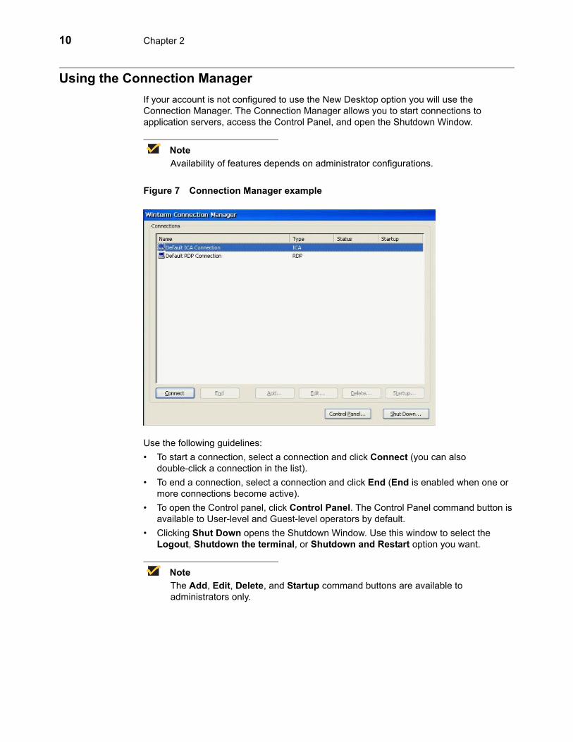
Using the Connection ManagerIf your account is not configured to use the New Desktop option you will use the Connection Manager. The Connection Manager allows you to start connections to application servers, access the Control Panel, and open the Shutdown Window.
NoteAvailability of features depends on administrator configurations.
Figure 7 Connection Manager example
Use the following guidelines:• To start a connection, select a connection and click Connect (you can also
double-click a connection in the list). • To end a connection, select a connection and click End (End is enabled when one or
more connections become active).• To open the Control panel, click Control Panel. The Control Panel command button is
available to User-level and Guest-level operators by default.• Clicking Shut Down opens the Shutdown Window. Use this window to select the
Logout, Shutdown the terminal, or Shutdown and Restart option you want.
NoteThe Add, Edit, Delete, and Startup command buttons are available to administrators only.

Getting Started 11
The Connection Manager also provides important information about a connection, including:• Icon - The icon preceding the listed name indicates the type of connection as follows:
• Computer terminal icon - Represents a standard thin-client, terminal emulation, or VPN connection.
• Telephone icon - Represents a dial-up connection.• Composite icon consisting of a computer terminal and a telephone - Indicates
that the standard connection will access the network through a dial-up server.• Name - The name of the connection assigned by the administrator.• Type - Supported connection types (the list that appears depends on the applications
installed on the thin client), including:• Citrix ICA Client• Dial-up Client• Ericom PowerTerm Terminal Emulator • Internet Explorer• Microsoft Remote Desktop Client• PPP over Ethernet (PPPoE)• VPN (PPTP) Client
• Status - The status of a connection can be either Active (if the connection is active) or blank (if the connection is not active).
• Startup - The startup of a connection can be either Autostart (if the connection is set to start at thin client startup) or blank (if the connection is not set to start at thin client startup).

12 Chapter 2
This page intentionally blank.
3 Setting-up the Thin Client
This chapter contains information to help you set up your thin client using the applications available in the Control Panel.
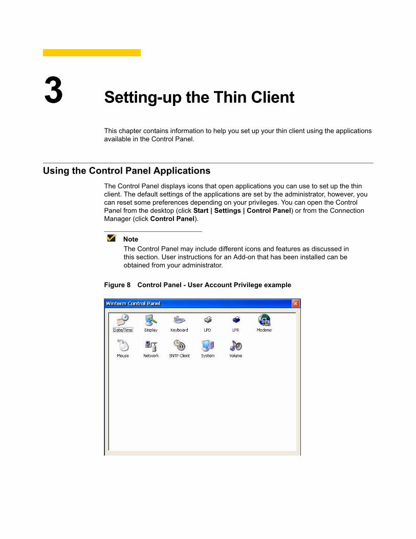
Using the Control Panel ApplicationsThe Control Panel displays icons that open applications you can use to set up the thin client. The default settings of the applications are set by the administrator, however, you can reset some preferences depending on your privileges. You can open the Control Panel from the desktop (click Start | Settings | Control Panel) or from the Connection Manager (click Control Panel).
NoteThe Control Panel may include different icons and features as discussed in this section. User instructions for an Add-on that has been installed can be obtained from your administrator.
Figure 8 Control Panel - User Account Privilege example
14 Chapter 3
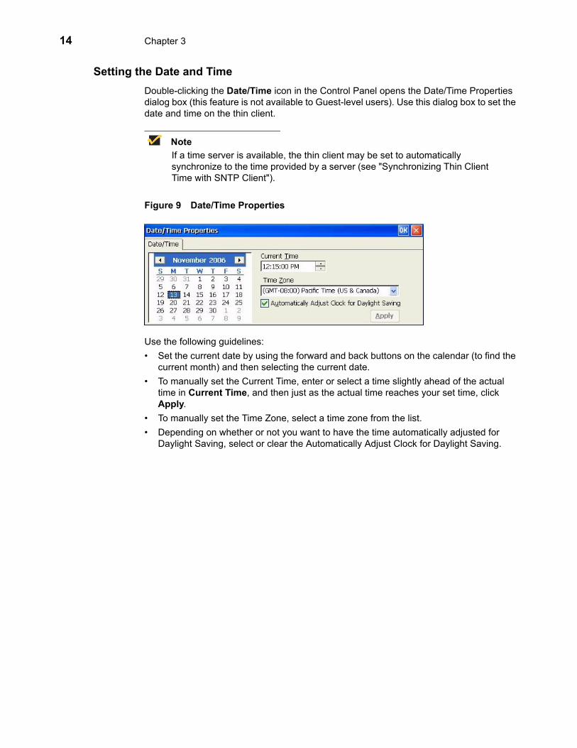
Setting the Date and TimeDouble-clicking the Date/Time icon in the Control Panel opens the Date/Time Properties dialog box (this feature is not available to Guest-level users). Use this dialog box to set the date and time on the thin client.
NoteIf a time server is available, the thin client may be set to automatically synchronize to the time provided by a server (see "Synchronizing Thin Client Time with SNTP Client").
Figure 9 Date/Time Properties
Use the following guidelines:• Set the current date by using the forward and back buttons on the calendar (to find the
current month) and then selecting the current date.• To manually set the Current Time, enter or select a time slightly ahead of the actual
time in Current Time, and then just as the actual time reaches your set time, click Apply.
• To manually set the Time Zone, select a time zone from the list.• Depending on whether or not you want to have the time automatically adjusted for
Daylight Saving, select or clear the Automatically Adjust Clock for Daylight Saving.
Setting-up the Thin Client 15
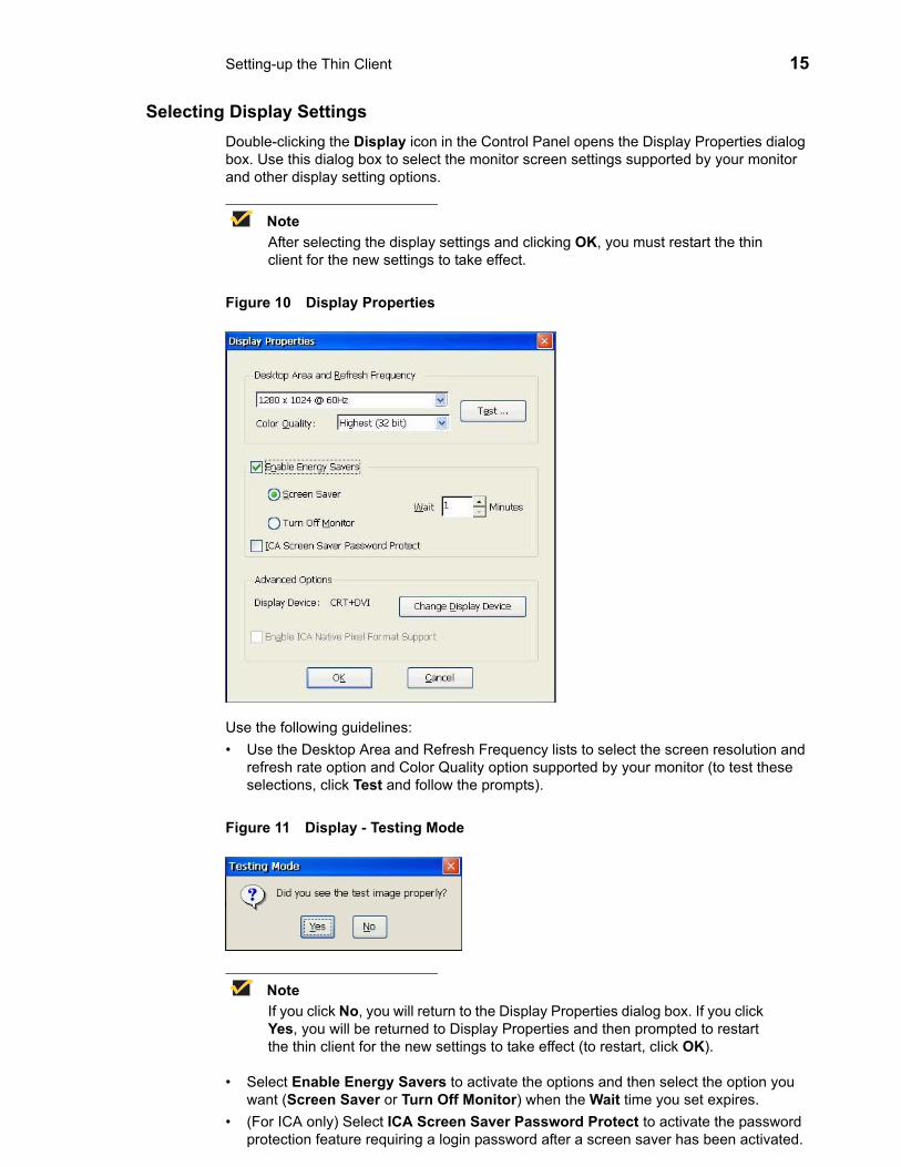
Selecting Display SettingsDouble-clicking the Display icon in the Control Panel opens the Display Properties dialog box. Use this dialog box to select the monitor screen settings supported by your monitor and other display setting options.
NoteAfter selecting the display settings and clicking OK, you must restart the thin client for the new settings to take effect.
Figure 10 Display Properties
Use the following guidelines:• Use the Desktop Area and Refresh Frequency lists to select the screen resolution and
refresh rate option and Color Quality option supported by your monitor (to test these selections, click Test and follow the prompts).
Figure 11 Display - Testing Mode
NoteIf you click No, you will return to the Display Properties dialog box. If you click Yes, you will be returned to Display Properties and then prompted to restart the thin client for the new settings to take effect (to restart, click OK).
• Select Enable Energy Savers to activate the options and then select the option you want (Screen Saver or Turn Off Monitor) when the Wait time you set expires.
• (For ICA only) Select ICA Screen Saver Password Protect to activate the password protection feature requiring a login password after a screen saver has been activated.

16 Chapter 3
• (For dual-monitor capable thin clients only) Click Change Display Device to open the Display Device dialog box. Use this dialog box to select the display option you want from the list (either CRT, DVI, CRT+DVI, or DVI+CRT; be sure to select the correct primary and secondary display for CRT+DVI or DVI+CRT). You can also select or clear the Extend my windows desktop check box (Extend my windows desktop allows you to drag items across your screen onto alternate monitors, or to resize a window to stretch it across more than one monitor. It is supported in the New Desktop user interface mode only; it is not supported in the Connection Manager user interface mode). After clicking OK, you will be prompted to restart the thin client for the changes to take effect (to restart, click OK).
Figure 12 Display Device
• (For ICA only) Select Enable ICA Native Pixel Format Support to activate this support feature and increase ICA performance (this feature will reduce RDP performance).
Setting Keyboard PropertiesDouble-clicking the Keyboard icon in the Control Panel opens the Keyboard Properties dialog box. Use this dialog box to select the keyboard language.
Figure 13 Keyboard Properties
Use the following guidelines:• Keyboard area:
• Type - Select the keyboard type from the list of supported keyboards.• Locale - Select one of the supported keyboard languages shown in Table 1.

Setting-up the Thin Client 17
NoteAn IEPC keyboard is required for any language other than English (US). The keyboard layouts are different for each of the languages in the list.
• NumLock on Boot - Select if you want the numeric keyboard to be active when the thin client starts.
• Character Repeat area:• Repeat delay slider control - Adjusts the repeat delay of keyboard characters.
Repeat delay determines how long the key must be held down before the character starts repeating.
• Repeat rate slider control - Adjusts the repeat rate of a keyboard character. Repeat rate determines how quickly the same character will appear on screen when the associated key is held down.
Table 1 Supported keyboard languages
Supported keyboard languages
Arabic (101) Hungarian
Arabic (102) Italian
Arabic (102) AZERTY Italian (142)
Belgian Dutch Japanese
Belgian French Korean
Brazilian (ABNT) Latin American
Canadian French Norwegian
Canadian French (Legacy) Polish (214)
Canadian Multi Standard Polish (Programmers)
Chinese Simplified - US Keyboard Portuguese
Chinese Traditional - US Keyboard Romanian
Croatian Russian
Czech Slovak
Danish Slovenian
Dutch Spanish
English (UK) Spanish Variation
English (US) Swedish
Finnish Swiss French
French Swiss German
German Turkish F
Greek Turkish Q
Hebrew US International

18 Chapter 3
Configuring Line Printer Daemon (LPD) ServicesA thin client can be configured to provide Line Printer Daemon (LPD) services (making the thin client a printer server receiving print jobs from one or more clients and spooling these jobs to a designated physical port). The LPD server receives print jobs sent to a named line printer queue from the LPR client and prints them on the designated printer. For information on LPR, refer to "Configuring LPR Settings."
NoteLPD service itself does not rely on static IP address to function, however, it is recommended that the LPD server (the thin client) be assigned a static IP address to avoid the need to re-configure the LPR clients due to LPD server IP address changes. To specify a static IP address for the LPD server (thin client), use Settings dialog box as described in "Configuring Network Adapters."
Double-clicking the LPD icon in the user or administrator Control Panel opens the LPD Config dialog box. Use this dialog box to select and configure an LPD server. Configuration allows a configuration to be created (New - see "Creating a New LPD Configuration"), edited (Edit - see "Editing an LPD Configuration"), or deleted (Delete - see "Deleting an LPD Configuration"). The remaining boxes and options define values common to all print queue configurations that the LPD Server manages.
Creating a New LPD ConfigurationTo create a new print queue configuration:
1. Double-click LPD in the Control Panel to open the LPD Config dialog box.
Figure 14 Initial LPD Config - New configuration
2. Select New.
3. Use the following guidelines (after configuring, be sure to click OK):
NoteInitially an LPD Server is disabled. All boxes and options are disabled except for Enable Printer, OK, and Cancel. To enable the LPD Server, select Enable Printer. A reboot is necessary after initially enabling the server. Similarly a reboot is necessary if the server is disabled by clearing Enable Printer.
• You must enter the name of the new print queue in Printer Name and select an output port in Port. In addition you can change the global settings Network Port and Extended Printer Init Delay to suit the needs of the current and any existing configurations.
Setting-up the Thin Client 19
• Printer Name actually refers to the print queue from which the server receives print jobs from an LPR client. The actual printer name may not match the print queue name. The name is case sensitive and is required. The LPD server can manage multiple print queues. Each queue is assigned a unique physical port specified by Port. This one-to-one correspondence between the queue name and physical port allows LPD to easily route print jobs to a designated printer. There are no fundamental limitations preventing the use of multiple physical ports for each named queue. However, no method is currently defined for this implementation that allows the identification of a specific port within a named queue.
• Port is the value of the physical port to which a printer is attached and the server sends the print job.
• Network Port is used to set a port value on which the LPD server listens for a print job from an LPR client. The LPD server listens on port 515 by default. You do not need to change this value unless the LPR client is sending a print job on a port other than the default port value.
• Selecting Extended Printer Init Delay gives the printer additional time to initialize. Enable this feature only if the printer requires additional time to initialize before printing. Otherwise, unnecessary delays may occur during printing.
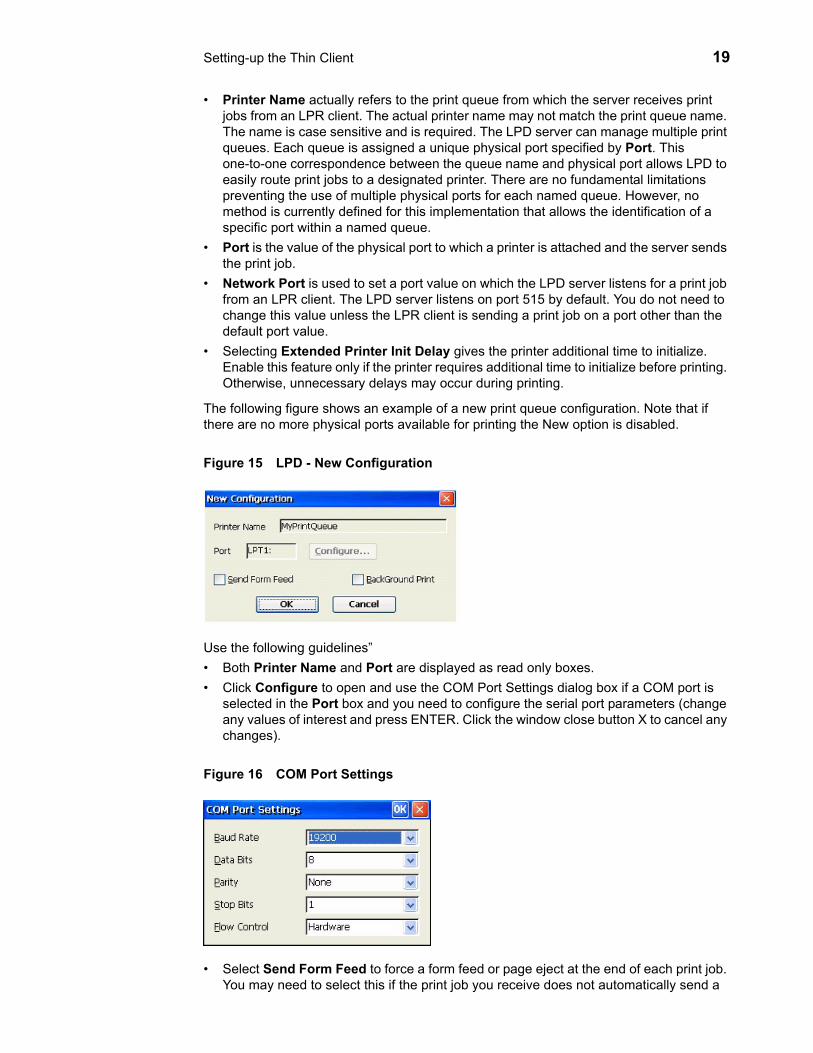
The following figure shows an example of a new print queue configuration. Note that if there are no more physical ports available for printing the New option is disabled.
Figure 15 LPD - New Configuration
Use the following guidelines”• Both Printer Name and Port are displayed as read only boxes.• Click Configure to open and use the COM Port Settings dialog box if a COM port is
selected in the Port box and you need to configure the serial port parameters (change any values of interest and press ENTER. Click the window close button X to cancel any changes).
Figure 16 COM Port Settings
• Select Send Form Feed to force a form feed or page eject at the end of each print job. You may need to select this if the print job you receive does not automatically send a

20 Chapter 3
form feed. But you may also receive an additional blank page if the print job you are receiving already has sent a form feed at the end of the print job.
• Selecting BackGround Print reduces the priority of the printing thread to a low level to reduce potential conflicts with priority foreground processes.
Editing an LPD ConfigurationTo edit a print queue configuration:
1. Double-click LPD in the Control Panel to open the LPD Config dialog box.
NoteYou may change any combination of values, including Printer Name. The following figure shows an example of an edit print queue configuration. Note that if there are no existing print queue configurations the Edit button is disabled.
Figure 17 Initial LPD Config - Edit configuration
2. Select Edit.
3. Use the configuration guidelines in "Creating a New LPD Configuration" to change any combination of values (after configuring, be sure to click OK).
The following figure shows the edit configuration screen after Port has been changed to COM1.
Figure 18 LPD - Edit Existing Configuration

Setting-up the Thin Client 21
Deleting an LPD ConfigurationTo delete a print queue configuration:
1. Double-click LPD in the Control Panel to open the LPD Config dialog box.
NoteIf there are no existing print queue configurations the Delete button is disabled.
Figure 19 Initial LPD Config - Edit configuration
2. Select Delete.
3. Click OK.

22 Chapter 3
Configuring LPR SettingsA thin client can also be configured as an LPR client. LPR is a component of the Line Printer Daemon Protocol. LPR works in conjunction with the line printer daemon (LPD) server. LPR is a client sending a print job to a server. LPD is a server receiving print tasks from one or more LPR clients and spooling these jobs to a physical port. The purpose of LPR is to assign a print job to a named line printer queue managed by the LPD server. LPR can be configured by double-clicking the LPR icon in the user or administrator Control Panel and using the LPR Configuration dialog box.
NoteLPR is supported for RDP connections, but not supported for ICA connections.
Figure 20 LPR Configuration
Use the following guidelines:• Host Name and Host Address - You can enter either a symbolic name or a dotted
decimal IP address for the LPD server. One or the other is required. The Host Name must resolve to a valid address. Using a Host Name is easier and more portable, since the IP address is dynamically determined, but it is not required.
• Port - The Port is used to set a port value of the LPD server to which the LPR client should send the print job. The LPD server listens to port 515 by default. You do not need to change this value unless the LPD server you are sending the print job to uses a port value other than the default.
• Queue - The Queue is the name of a specific queue managed by the LPD server to which the LPR client should send the print job. The behavior of the server is implementation dependent. Some servers will restrict printing to an explicitly specified queue, while others will dynamically create a queue name and then print the print job. The Queue name is case sensitive.
• Print Banner Page - Select Print Banner Page to enable printing an optional banner page that precedes the main print job. If this box is not selected the following boxes are disabled. Banner page printing is highly server dependent. Any of the following that should not be printed on the banner page should be left blank:• User Name - The User Name is optional and may be left blank. The maximum
length is 31 characters.• Job Name - The Job Name is optional and may be left blank. The maximum length
is 99 characters.• Class Name - The Class Name is optional and may be left blank. The maximum
length is 31 characters.

Setting-up the Thin Client 23
NoteYou can configure multiple thin clients with the same LPR settings, by pushing the desired registry settings to thin clients via a Wyse Device Manager script (for information on Wyse Device Manager, refer to the Wyse Device Manager documentation on the Wyse Web site.
After configuring the LPR client settings, you must configure the desired application to direct a print job to the LPR client. LPR client creates a logical port LPT8 on the thin client. You need to configure your application to send a print job to a printer attached to LPT8 Use the following guidelines when configuring an individual application.
NoteCurrently RDP is the only application confirmed to work with LPT8. However, any application that recognizes LPT8 as a printer port should be able to print to an LPD server using the LPR client.
To configure a client printer in order to use the LPR Client from a RDP session:
1. Double-click Client Printers in the Control Panel to open the Client Printers dialog box and click Add.
Figure 21 LPR Configuration - select port LPT8
2. Select LPT8 for the port. This is the unique port name that identifies the LPR client logical port.
3. Click Next and add a printer that corresponds to the printer attached to your LPD server. If you simply want to print text, you can select Generic/Text Only. However, if you want to print graphics you must select an actual printer.
4. After selecting your printer, you will be asked to name it. The name you choose is arbitrary, since this name is not used by the LPR client. However, it is helpful to give it a meaningful name so that you can easily identify it when printing from a RDP session.
5. After connecting to an RDP session, you can then print to the LPD Server by selecting the printer you have configured to use the LPR client.

24 Chapter 3
Configuring ModemsDouble-clicking the Modems icon in the Control Panel opens the Modem Settings dialog box (this feature is not available to Guest-level users). Use this dialog box to enter or modify control commands required to operate the modem. If Integrated Services Digital Network (ISDN) is to be used, be sure to click ISDN Settings to open a dialog box for entering ISDN parameters.
NoteRefer to the modem device instructions for listings of modem AT commands available for the modem.
Figure 22 Modem Settings
Configuring ISDN Settings
Clicking ISDN Settings in the Modem Settings dialog box opens the ISDN Settings dialog box. Use this dialog box to enter the parameters and protocol information for an Integrated Services Digital Network (ISDN) modem.
Figure 23 Modems - ISDN Settings (example of EiCon-Tech modem defaults)
Setting-up the Thin Client 25
Use the following guidelines:• Modem Name - Read-only display of the manufacturer and model of the modem
selected in the Modem Settings dialog box.• Primary ISDN Parameters area:
• Switch Type - Select the switch type from the drop-down list.• Service Profile ID 1 and Service Profile ID 2 - Enter the SPID numbers provided
by your telephone company.• Protocol - Select the ISDN protocol required by the telephone company.
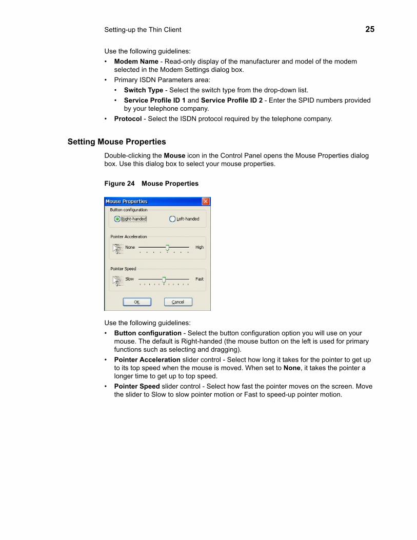
Setting Mouse PropertiesDouble-clicking the Mouse icon in the Control Panel opens the Mouse Properties dialog box. Use this dialog box to select your mouse properties.
Figure 24 Mouse Properties
Use the following guidelines:• Button configuration - Select the button configuration option you will use on your
mouse. The default is Right-handed (the mouse button on the left is used for primary functions such as selecting and dragging).
• Pointer Acceleration slider control - Select how long it takes for the pointer to get up to its top speed when the mouse is moved. When set to None, it takes the pointer a longer time to get up to top speed.
• Pointer Speed slider control - Select how fast the pointer moves on the screen. Move the slider to Slow to slow pointer motion or Fast to speed-up pointer motion.

26 Chapter 3
Configuring Network AdaptersDouble-clicking the Network icon in the Control Panel opens the Network Adapters Configuration dialog box (this feature is not available to Guest-level users). Use this dialog box to view the list of adapters installed on the thin client and to select the Network Adapters Configuration settings.
NoteFor information on configuring thin clients containing the optional Internal Wireless feature, refer to "Configuring the Optional Internal Wireless Feature." For information on configuring available wireless Add-ons, refer to the Add-on Administrators Guide: Wyse® WintermTM 3 series, Based on Microsoft® Windows® CE.
Figure 25 Network Adapters Configuration - without Internal Wireless feature
Use the following guidelines:• Select Check Network on BOOT if you want to have the thin client check the network
upon thin client start-up.• Select Accept terminal name from DHCP if you want to use terminal names assigned
from the DHCP server.• Enter the Terminal Name if you are not selecting Accept terminal name from DHCP.• Select the supported Network Speed from the list.• To change the configuration settings of an adapter, select it and click Properties to
open and use the Settings dialog box.
NoteIt is recommended that you modify default configuration settings according to instructions provided by your administrator.

Setting-up the Thin Client 27
Configuring the Optional Internal Wireless FeatureIf your thin client contains the optional Internal Wireless feature, use the information in this section to configure it.
To configure the optional Internal Wireless feature:
1. Double-click the Network icon in the Control Panel to open the Network Adapters Configuration dialog box (this feature is not available to Guest-level users).
NoteFor the New Desktop option, you can also double-click the wireless icon in the right corner of the taskbar to open the Property dialog box and continue with step 4.
Figure 26 Network Adapters Configuration - with Internal Wireless feature
2. Select the Internal Wireless from the list and click Properties to open the Settings dialog box.
Figure 27 Settings - Internal Wireless
3. Click Wireless Property to open the Property dialog box.
4. Click the Wireless Information tab.

28 Chapter 3
Figure 28 Property - Internal Wireless
From the Wireless Information tab you can configure settings for different wireless encryption and access control parameters. Depending on your wireless environment, continue with the set of procedures you need as described in "Without Wired Equivalent Privacy (WEP) Encryption," "With Wired Equivalent Privacy (WEP) Encryption," "With 802.1x Authentication - EAP-MD5 CHAP," "With 802.1x Authentication - PEAP-MSCHAPv2," "With 802.1x Authentication - EAP-TLS."
Without Wired Equivalent Privacy (WEP) Encryption
In this case, the wireless access point does not need encryption. Under this open system of authentication, any wireless station can request authentication. The station that needs to authenticate with another wireless station sends an authentication management frame that contains the identity of the sending station. The receiving station then returns a frame that indicates whether it recognizes the sending station.
1. Double-click Add New in the network list of the Wireless Information tab to open the Wireless Properties dialog box.
Figure 29 Wireless Properties without encryption
2. Enter the SSID of the wireless access point to which you want to connect and select Disabled for the Encryption type.
3. Click OK.

Setting-up the Thin Client 29
With Wired Equivalent Privacy (WEP) Encryption
In this case, the wireless access point uses encryption. Under this system of authentication, 64- bit or 128-bit encryption can be used.
1. Double-click Add New in the network list of the Wireless Information tab to open the Wireless Properties dialog box.
Figure 30 Wireless Properties with encryption
2. Enter the SSID of the wireless access point to which you want to connect and select WEP for the Encryption type.
3. Select Open for the Authentication type.
4. Enter the Network key (for 64-bit encryption, the key length must be 10 characters; for 128-bit encryption, the key length must be 26 characters).
5. Enter the Key Index.
6. Click OK.

30 Chapter 3
With 802.1x Authentication - EAP-MD5 CHAP
In this case, you will configure the adapter to connect to the access point to which you want to connect using EAP-MD5 authentication.
1. Double-click Add New in the network list of the Wireless Information tab to open the Wireless Properties dialog box.
Figure 31 Wireless Properties example using EAP-MD5 CHAP
2. Enter the SSID of the wireless access point to which you want to connect.
3. Depending on your access point set-up, use the following guidelines:• If your access point is set up to use WEP, select WEP for the Encryption type.• If your access point is set up to use TKIP, select TKIP for the Encryption type.• If your access point is set up to use open authentication, select Open for the
Authentication type.• If your access point is set up to use WPA authentication, select WPA for the
Authentication type.
4. Select The key is provided automatically if your access point supports WEP key broadcasting. Otherwise, clear The key is provided automatically and manually enter a Network key that matches your access point WEP key settings.
5. Select Enable 802.1X authentication on this network, and then select MD5-Challenge for the EAP type.
6. Click OK (after the thin client is associated with the access point and the User Logon dialog box appears, enter your logon account credentials, and then click OK).
Setting-up the Thin Client 31
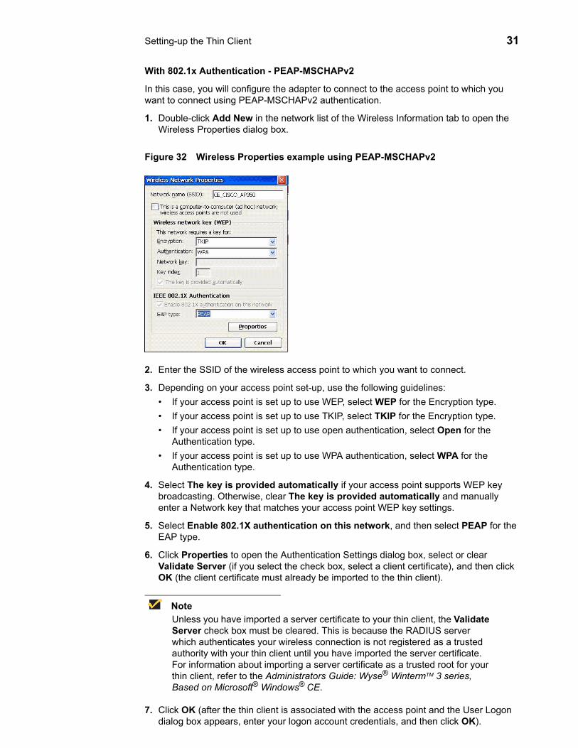
With 802.1x Authentication - PEAP-MSCHAPv2
In this case, you will configure the adapter to connect to the access point to which you want to connect using PEAP-MSCHAPv2 authentication.
1. Double-click Add New in the network list of the Wireless Information tab to open the Wireless Properties dialog box.
Figure 32 Wireless Properties example using PEAP-MSCHAPv2
2. Enter the SSID of the wireless access point to which you want to connect.
3. Depending on your access point set-up, use the following guidelines:• If your access point is set up to use WEP, select WEP for the Encryption type.• If your access point is set up to use TKIP, select TKIP for the Encryption type.• If your access point is set up to use open authentication, select Open for the
Authentication type.• If your access point is set up to use WPA authentication, select WPA for the
Authentication type.
4. Select The key is provided automatically if your access point supports WEP key broadcasting. Otherwise, clear The key is provided automatically and manually enter a Network key that matches your access point WEP key settings.
5. Select Enable 802.1X authentication on this network, and then select PEAP for the EAP type.
6. Click Properties to open the Authentication Settings dialog box, select or clear Validate Server (if you select the check box, select a client certificate), and then click OK (the client certificate must already be imported to the thin client).
NoteUnless you have imported a server certificate to your thin client, the Validate Server check box must be cleared. This is because the RADIUS server which authenticates your wireless connection is not registered as a trusted authority with your thin client until you have imported the server certificate. For information about importing a server certificate as a trusted root for your thin client, refer to the Administrators Guide: Wyse® WintermTM 3 series, Based on Microsoft® Windows® CE.
7. Click OK (after the thin client is associated with the access point and the User Logon dialog box appears, enter your logon account credentials, and then click OK).

32 Chapter 3
With 802.1x Authentication - EAP-TLS
In this case, you will configure the adapter to connect to the access point to which you want to connect using EAP-TLS authentication.
1. Double-click Add New in the network list of the Wireless Information tab to open the Wireless Properties dialog box.
Figure 33 Wireless Properties example using EAP-TLS
2. Enter the SSID of the wireless access point to which you want to connect.
3. Depending on your access point set-up, use the following guidelines:• If your access point is set up to use WEP, select WEP for the Encryption type.• If your access point is set up to use TKIP, select TKIP for the Encryption type.• If your access point is set up to use open authentication, select Open for the
Authentication type.• If your access point is set up to use WPA authentication, select WPA for the
Authentication type.
4. Select The key is provided automatically if your access point supports WEP key broadcasting. Otherwise, clear The key is provided automatically and manually enter a Network key that matches your access point WEP key settings.
5. Select Enable 802.1X authentication on this network, and then select TLS for the EAP type.
6. Click Properties to open the Authentication Settings dialog box, select or clear Validate Server (if you select the check box, select a client certificate), and then click OK (the client certificate must already be imported to the thin client).
NoteUnless you have imported a server certificate to your thin client, the Validate Server check box must be cleared. This is because the RADIUS server which authenticates your wireless connection is not registered as a trusted authority with your thin client until you have imported the server certificate. For information about importing a server certificate as a trusted root for your thin client, refer to the Administrators Guide: Wyse® WintermTM 3 series, Based on Microsoft® Windows® CE.
7. Click OK (after the thin client is associated with the access point and the User Logon dialog box appears, enter your logon account credentials, and then click OK).

Setting-up the Thin Client 33
Synchronizing Thin Client Time with SNTP ClientDouble-clicking the SNTP Client icon in the Control Panel opens the SNTP Client dialog box (this feature is not available to Guest-level users). Use this dialog box to synchronize the thin client clock to the time provided by a Simple Network Time Protocol (SNTP) server.
Figure 34 SNTP Client
SNTP Server lists servers that will be contacted to provide the time synchronization signal. The server list can be modified by using the Add, Edit, and Remove command buttons.
The synchronization can be set to occur upon intervals by using the Enable Synchronization check box (select the check box and enter the interval hours and minutes you want), or synchronization can be initiated immediately by clicking Synchronize. An error message appears if synchronization fails. This local synchronization feature can be used to test availability of listed SNTP servers.
To modify the server list, use the following guidelines:• Add - To add a server to the list, click Add to open the Add SNTP Server dialog box,
enter the SNTP server, and click OK.
Figure 35 SNTP - Add SNTP Server
• Edit - To edit a server in the list, select a server in the list, click Edit to open the Edit SNTP Server dialog box, clear the information, enter the SNTP server, and click OK.
Figure 36 SNTP - Edit SNTP Server
• Remove - To remove a server from the list, select it, click Remove, and click Yes to confirm.

34 Chapter 3
Using the System Information FeaturesDouble-clicking the System icon in the Control Panel opens the System Info dialog box. Use this dialog box to view information about the thin client, system, and thin client memory. You can also use this dialog box to allocate thin client memory.
General Tab
The General tab displays the manufacturer name, product information, installed memory, operating system version, copyright information, and so on. It also contains a check box (active for administrators only) that allows the administrator to reset the thin client to factory default settings.
Figure 37 System Info - General tab
System Info Tab
The System Info tab displays the system information (including, the Network Settings, Hardware Number, Flash Memory information, and so on).
Figure 38 System Info - System Info tab

Setting-up the Thin Client 35
Memory Tab
The Memory tab displays the memory allocated to run programs and the memory allocated for storage room. Use the slider to allocate unused RAM to either Storage Memory or Program Memory, and click OK.
Figure 39 System Info - Memory tab
Setting Volume PropertiesDouble-clicking the Volume icon in the Control Panel opens the Volume Properties dialog box. Use this dialog box to set the volume and to enable sounds for various events and conditions.
Figure 40 Volume Properties

36 Chapter 3
Modifying PNAgent Settings on the Thin ClientDepending on administrator configurations, you may be able to modify Program Neighborhood Agent (PNAgent) settings on the thin client through the Global ICA Client Settings icon in the Control Panel.
Enabling the Program Neighborhood Agent
To enable the PNAgent on the thin client:
1. Double-click the Global ICA Client Settings icon in the control panel (or right-click an exiting ICA connection and select Edit Connection) to open the Global ICA Client Settings dialog box, and select the Options tab.
2. Select the Enable PNAgent check box
3. Enter the Server URL in the PNAgent Configuration window and click Update.
4. Enter your logon credentials.
Depending on how the PNAgent has been configured on the server by the administrator, you may be given the option to save your password. If you select this option, you will not be prompted for your password again until the next time you change it. If you do not select this option, you will be prompted for your password each time you connect or reboot the thin client.
NoteIf the only logon mode available is Prompt User (which appears as a selected and dimmed out option on the Server tab), it means that you will be prompted to enter your logon credentials at the start of each session.
5. When you are finished configuring your settings, click OK to close the Global ICA Client Settings dialog box.
Changing the Server URL
The PNAgent requires the URL to a configuration file on the server running the Web Interface. This file contains the information the PNAgent needs for users to access remote applications on a local device.
After enabling the PNAgent, you can change the server URL on the thin client at any time by completing the following procedures:
1. Double-click the Global ICA Client Settings icon in the control panel (or right-click an exiting ICA connection and select Edit Connection) to open the Global ICA Client Settings dialog box, and select the Preferences tab.
2. Click PNAgent Settings.
3. Select the Server tab to display the currently selected URL.
4. Click Change, and enter the new server URL.
5. Click Update to apply the update and return to the Server tab.
NoteFor more information on the Citrix PNAgent, refer to the Citrix ICA documentation.

Figures1 Terminal Login 32 Single Button Connect 43 AutoLogin countdown 44 Shutdown Window 75 Desktop - User example 86 Taskbar and Start Menu Properties 97 Connection Manager example 108 Control Panel - User Account Privilege example 139 Date/Time Properties 1410 Display Properties 1511 Display - Testing Mode 1512 Display Device 1613 Keyboard Properties 1614 Initial LPD Config - New configuration 1815 LPD - New Configuration 1916 COM Port Settings 1917 Initial LPD Config - Edit configuration 2018 LPD - Edit Existing Configuration 2019 Initial LPD Config - Edit configuration 2120 LPR Configuration 2221 LPR Configuration - select port LPT8 2322 Modem Settings 2423 Modems - ISDN Settings (example of EiCon-Tech modem defaults) 2424 Mouse Properties 2525 Network Adapters Configuration - without Internal Wireless feature 2626 Network Adapters Configuration - with Internal Wireless feature 2727 Settings - Internal Wireless 2728 Property - Internal Wireless 2829 Wireless Properties without encryption 2830 Wireless Properties with encryption 2931 Wireless Properties example using EAP-MD5 CHAP 3032 Wireless Properties example using PEAP-MSCHAPv2 3133 Wireless Properties example using EAP-TLS 3234 SNTP Client 3335 SNTP - Add SNTP Server 3336 SNTP - Edit SNTP Server 3337 System Info - General tab 3438 System Info - System Info tab 3439 System Info - Memory tab 3540 Volume Properties 35

38

Tables1 Supported keyboard languages 17

Users Guide
Wyse® WintermTM 3 series, Based on Microsoft® Windows® CEIssue: 121906
Written and published by: Wyse Technology Inc., December 2006
Created using FrameMaker® and Acrobat®