User's Guide Title Pro-dialog Control 4 for Air & Water Cooled Chillers Series 30 Gx & Hxc Version 2
100
USER'S GUIDE TITLE: PRO-DIALOG CONTROL 4 FOR AIR & WATER COOLED CHILLERS SERIES 30 GX & HXC VERSION 2 REV: original Property of CARRIER S.A. Montluel. Not to be disclosed to persons outside the organization without Written authorization SYNOPTIQUE CARRIER - AIR-COOLED BI CIRCUIT - ABC PARTNERS 08/06/98 DATE SPECIFICATION N° COPY N° ECG CARRIER S.A. ECG-UG-00-001 06/12/00
-
Upload
vitor-santos -
Category
Documents
-
view
423 -
download
39
Transcript of User's Guide Title Pro-dialog Control 4 for Air & Water Cooled Chillers Series 30 Gx & Hxc Version 2

USER'S GUIDE
TITLE: PRO-DIALOG CONTROL 4 FOR AIR & WATER COOLEDCHILLERS SERIES 30 GX & HXC VERSION 2
REV: original
Property of CARRIER S.A. Montluel.Not to be disclosed to persons outside the organization without Written authorization
SYNOPTIQUE CARRIER - AIR-COOLED BI CIRCUIT - ABC PARTNERS 08/06/98
DAT
ESP
ECIF
ICAT
ION
N°
CO
PY N
° ECG CARRIER S.A. E
CG
-UG
-00-
001
06/1
2/00

22
21
20
19
18
17
16
15
14
13
12
11
10
9
8
7
6
5
4
3
2
Carrier Carrier Service1COMPANYNAMECOPY #
Ba-Tung PHAMORIGINATOR
CARRIER SAUSER'S GUIDE FOR
30GX&HX PRO_DIALOG 4 V.2ECG-UG-02-002
Rev: originalPage: /98
© CARRIER S.ANOT TO BE DISCLOSED TO PERSONS OUTSIDE CARRIER ORGANIZATION

1 - INTRODUCTION . . . . . . . . . . . . . . . . . . . . . . . . . . . . . . . . . . . 41.1 - About This Manual . . . . . . . . . . . . . . . . . . . . . . . . . . . . . 41.2 - Manual Structure and contents . . . . . . . . . . . . . . . . . . 4
2 - GENERAL DESCRIPTION . . . . . . . . . . . . . . . . . . . . . . . . . . . 42.1 - Generalities . . . . . . . . . . . . . . . . . . . . . . . . . . . . . . . . . . . 42.1 - Software Reference Number . . . . . . . . . . . . . . . . . . . . 72.3 - Abbreviations Used . . . . . . . . . . . . . . . . . . . . . . . . . . . . 7
3 - HARDWARE DESCRIPTION . . . . . . . . . . . . . . . . . . . . . . . . 83.1 - Produc Component . . . . . . . . . . . . . . . . . . . . . . . . . . . . 8
3.1.1 - Basic Board . . . . . . . . . . . . . . . . . . . . . . . . . . . . . 103.1.2 - CCN/Clock Option Board . . . . . . . . . . . . . . . . . 103.1.3 - Screw Compressor Protection Module . . . . . 11
3.1.3.1 - Screw Compressor Module Layout 113.1.3.2 - Compressor Part Number/MTA Header
Configuration . . . . . . . . . . . . . . . . . . . . 12
3.1.4 - 4 xDO Board . . . . . . . . . . . . . . . . . . . . . . . . . . . . 123.1.4.1 - General . . . . . . . . . . . . . . . . . . . . . . . . 123.1.4..2 - Terminal J4 Description . . . . . . . . 12
3.1.5 - AUX Boards . . . . . . . . . . . . . . . . . . . . . . . . . . . . . 133.1.5.1 - General . . . . . . . . . . . . . . . . . . . . . . . . 13
3.1.6 - EXV Driver Board . . . . . . . . . . . . . . . . . . . . . . . . 143.1.7 - 4 x AI - 2 x AO Board . . . . . . . . . . . . . . . . . . . . 143.1.8 - Aquasnap Basic Board . . . . . . . . . . . . . . . . . . 16
3.2 - Pressure Sensors . . . . . . . . . . . . . . . . . . . . . . . . . . . . . . 173.2.1 - High Pressure Side Sensors . . . . . . . . . . . . . 173.2.2 - Large Band Pressure Sensors . . . . . . . . . . . 173.2.3 - Suction and economizer Pressure Sensors 18
3.3 - Thermistors . . . . . . . . . . . . . . . . . . . . . . . . . . . . . . . . . . . 183.3.1 - Discharge Gas temperature . . . . . . . . . . . . . . 183.3.2 - 5K Resistor : Resistance vs Temperature
Curve . . . . . . . . . . . . . . . . . . . . . . . . . . . . . . . . . 19
4 - CONTROL DESCRIPTION . . . . . . . . . . . . . . . . . . . . . . . . . . 20
4.1 - General . . . . . . . . . . . . . . . . . . . . . . . . . . . . . . . . . . . . . . 204.2 - Configuration . . . . . . . . . . . . . . . . . . . . . . . . . . . . . . . . . 20
4.2.1 - General . . . . . . . . . . . . . . . . . . . . . . . . . . . . . . . . 204.2.2 - Main Interface Configuration sub menu
structure . . . . . . . . . . . . . . . . . . . . . . . . . . . . . . . 204.2.3 - Factory Configuration . . . . . . . . . . . . . . . . . . . 21
4.2.3.1 - Factory configuration from Service Tool . . . . . . . . . . . . . . . . . . . . . . . . . . . . 21
4.2.3.2 - Factory configuration from Main Interface . . . . . . . . . . . . . . . . . . . . . . . . 23
4.2.3.3 - Economizer TQ valve FeedbackSignal Wiring . . . . . . . . . . . . . . . . . . . . 24
4.2.4 - Service Configuration . . . . . . . . . . . . . . . . . . . 254.2.4.1 - Service 1 configuration from Service
Tool . . . . . . . . . . . . . . . . . . . . . . . . . . . . 254.2.4.2 - Service 1 configuration from Main
Interface . . . . . . . . . . . . . . . . . . . . . . . . 274.2.4.3 - Service 2 configuration from Service
Tool . . . . . . . . . . . . . . . . . . . . . . . . . . . . 284.2.4.4 - Service 2 configuration from Main
Interface . . . . . . . . . . . . . . . . . . . . . . . . 294.2.4.5 - Service 3 configuration from Service
Tool . . . . . . . . . . . . . . . . . . . . . . . . . . . . 304.2.4.6 - Service 3 configuration from Main
Interface . . . . . . . . . . . . . . . . . . . . . . . . 31
4.2.4.7 - Service 4 configuration from Service Tool . . . . . . . . . . . . . . . . . . . . . . . . . . . . 31
4.2.4.8 - Service 4 configuration from Main Interface, runtime sub menu . . . . . . 31
4.2.5 - User Configuration . . . . . . . . . . . . . . . . . . . . . . 32
4.2.6 - Network Configuration . . . . . . . . . . . . . . . . . . 324.2.6.1 - General . . . . . . . . . . . . . . . . . . . . . . . 324.2.6.2 - Configuring a Control as a
Broadcast Acknowledger . . . . . . . . 324.2.6.3 - Setting Time and Date . . . . . . . . . . 324.2.6.4 - Alarm Configuration Table . . . . . . 334.2.6.5 - Master/Slave Configuration . . . . . 35
4.3 - Cooler Interlock Contact . . . . . . . . . . . . . . . . . . . . . . . . 364.4 - Cooler heater control . . . . . . . . . . . . . . . . . . . . . . . . . . . 36
4.5 - Oil heater control . . . . . . . . . . . . . . . . . . . . . . . . . . 364.6 - Motor cooling control without plate exchanger
economizer . . . . . . . . . . . . . . . . . . . . . . . . . . . . . . . . . . . . 364.7 - Motor cooling control without sub cooling plate
exchanger economizer . . . . . . . . . . . . . . . . . . . . . . . . . . 374.7.1 - Motor cooling with TQ feedback Signal Control 374.8 - Capacity Control . . . . . . . . . . . . . . . . . . . . . . . . . . . . . . . 38
4.8.1 - Logic Description . . . . . . . . . . . . . . . . . . . . . . . 384.8.1.1 - Basic Logic . . . . . . . . . . . . . . . . . . . 384.8.1.2 - Z Multiplier Calculation . . . . . . . . 384.8.1.3 - Overrides . . . . . . . . . . . . . . . . . . . . 39
4.9 - Compressors & loaders loading sequence . . . . . . . 404.9.1 - General Description . . . . . . . . . . . . . . . . . . . . . 404.9.2 - Compressor capacity determination . . . . . . 414.9.3 - Staged Loading Increasing Capacity Logic 414.9.4 - Equal Loading Increasing Capacity Logic
with close control = NO . . . . . . . . . . . . . . . . . 414.9.5 - Equal Loading Increasing Capacity Logic
with close control = YES . . . . . . . . . . . . . . . . 424.9.6 - Equal Loading Decreasing Capacity Logic
with close control = YES . . . . . . . . . . . . . . . . 424.9.7 - Equal Loading Decreasing Capacity Logic
with close control = NO . . . . . . . . . . . . . . . . . 434.9.8 - Staged Loading Decreasing Capacity Logic
with close control = NO . . . . . . . . . . . . . . . . . 434.9.9 - Staged Loading Decreasing Capacity Logic
with close control = YES . . . . . . . . . . . . . . . . 444.10 - EXV Control . . . . . . . . . . . . . . . . . . . . . . . . . . . . . . . . . . 45
4.10.1 - General . . . . . . . . . . . . . . . . . . . . . . . . . . . . . . . 454.10.2 - Overrides . . . . . . . . . . . . . . . . . . . . . . . . . . . . . 45
4.11 - Air Cooled Condensing Pressure Control . . . . . . . 464.12.1 - Air Cooled Condensing Pressure Control -
Fan staging with AUX board . . . . . . . . . . . . . . . . . 464.12.2 - Air Cooled Condensing Pressure Control -
Fan staging . . . . . . . . . . . . . . . . . . . . . . . . . . . . . . . . 464.13 - Water Cooled Condensing Pressure Control . . . . 474.14 - High Pressure Override . . . . . . . . . . . . . . . . . . . . . . . 484.15 - High Current Override . . . . . . . . . . . . . . . . . . . . . . . . . 48
CONTENTS
CARRIER SAUSER'S GUIDE FOR
30GX&HX PRO_DIALOG 4 V.2ECG-UG-02-002
Rev: originalPage:2 /98
© CARRIER S.ANOT TO BE DISCLOSED TO PERSONS OUTSIDE CARRIER ORGANIZATION

4.16 - Stopping Function . . . . . . . . . . . . . . . . . . . . . . . . . . . . 484.16.1 - Stopping a compressor by capacity
unloading . . . . . . . . . . . . . . . . . . . . . . . . . . . . . 484.16.2 - Stopping the unit by manual command
(OFF) . . . . . . . . . . . . . . . . . . . . . . . . . . . . . . . . . 484.16.3 - Stopping a circuit by failure . . . . . . . . . . . . . 48
4.17 - Oil pressure control . . . . . . . . . . . . . . . . . . . . . . . . . . . 494.17.1 - Oil pressure setpoint determination . . . . . 494.17.2 - Oil pump control . . . . . . . . . . . . . . . . . . . . . . . 494.17.3 - Low oil pressure alarm determination . . . . 494.17.4 - Differential Oil Pressure Setpoint 1
alarm condition summary . . . . . . . . . . . . . . . 504.18 - Reclaim Operation . . . . . . . . . . . . . . . . . . . . . . . . . . . . 51
4.18.1 - General Description . . . . . . . . . . . . . . . . . . . 514.18.2 - Reclaim to Air Cooled Changeover
Initiation . . . . . . . . . . . . . . . . . . . . . . . . . . . . . . . 514.18.3 - Air Cooled To Reclaim Changeover
Initiation . . . . . . . . . . . . . . . . . . . . . . . . . . . . . . . 524.18.4 - Reclaim Operation hr_status
Description . . . . . . . . . . . . . . . . . . . . . . . . . . . . 524.18.5 - Reclaim Operation Using Air Cooled
Exchanger . . . . . . . . . . . . . . . . . . . . . . . . . . . . 524.18.6 - Reclaim Condenser Water Valve Control 524.18.7 - Reclaim Condenser Heater Control . . . . . 52
4.19 - Two Units Master/Slave Control . . . . . . . . . . . . . . . . 534.19.1 - General . . . . . . . . . . . . . . . . . . . . . . . . . . . . . . . 534.19.2 - Abnormal Conditions . . . . . . . . . . . . . . . . . . 55
5 - CCN ALARM MESSAGES . . . . . . . . . . . . . . . . . . . . . . . . . . . 57
6 - CCN COMPATIBILITY . . . . . . . . . . . . . . . . . . . . . . . . . . . . . . 60
7 - PRO_DIALOG 4 DOWNLOADER ADDENDUMINFORMATION . . . . . . . . . . . . . . . . . . . . . . . . . . . . . . . . . . . . 60
Appendix A - CCN DIPSLAY, SETPOINT, MAINTENANCE,CONFIGURATION TABLE SCREENS . . . . . . . 61
Appendix B - CCN Variables . . . . . . . . . . . . . . . . . . . . . . . . . . . . 76Appendix C - Wiring Schemes . . . . . . . . . . . . . . . . . . . . . . . . . . 83Appendix D - JBUS memory with GX& HX
default configuration . . . . . . . . . . . . . . . . . . . . . . . . 96Appendix E - SAM Screen . . . . . . . . . . . . . . . . . . . . . . . . . . . . . . 97Appendix F - CCN Network Example . . . . . . . . . . . . . . . . . . . . . 98
CONTENTS
CARRIER SAUSER'S GUIDE FOR
30GX&HX PRO_DIALOG 4 V.2ECG-UG-02-002
Rev: originalPage:3 /98
© CARRIER S.ANOT TO BE DISCLOSED TO PERSONS OUTSIDE CARRIER ORGANIZATION

1 - INTRODUCTION
1.1 - ABOUT THIS MANUAL
This manual is intended to be used as an additional guide for using and configuring the Pro-Dialog control forthe 30GX & HX chillers. The use of this document does not substitute the IOM.
This manual is intended for use by Service organizations inside the Carrier corporation. It is delivered onthe express condition that it is not to be disclosed, reproduced in whole or in part, or used formanufacture by anyone other than Carrier Corporation.
1.2 - MANUAL STRUCTURE AND CONTENTS
This manual includes the following sections:
v Introduction
v Product general description
v Hardware description
v Control description
v Appendixes
The introduction and product general description sections contain information about this manual as an overviewof the 30GX&HX Pro-Dialog Plus controls.
The hardware section provides complete information on boards, devices and connections used by the product.
The control description section is divided in several subsections. First provides a main description of hardwareconfiguration. This subsection provides sufficient information to runs the control in the most operating cases. Formore complete information, use the remaining sections and also IOM. Second subsection describes all the unitconfiguration and the methods to modify it. The last subsections describe the unit control logic’s.
2 - GENERAL DESCRIPTION
2.1 - GENERALITIES
PRO-DIALOG is a system for controlling units which use screw compressors:w Dual circuits
w Air cooled and water cooled chillers
w Non reversible heat machines
PRO-DIALOG controls compressors and loaders needed to maintain the desired leaving or entering watercontrol point. It automatically sets the position of the electronic expansion valve to maintain a correct refrigerantflow in the cooler. For air cooled units it controls the operation of the fans to maintain the correct condensingpressure in each circuit.
Safety circuits in the unit are constantly monitored by PRO-DIALOG to ensure its safe operation. PRO-DIALOGalso gives access to a Quick Test program covering all inputs and outputs excepted compressors outputs.
The control features of the 30GX&HX Pro-Dialog Plus are divided into standard features and options (additional board needed):
CARRIER SAUSER'S GUIDE FOR
30GX&HX PRO_DIALOG 4 V.2ECG-UG-02-002
Rev: originalPage: 4/98
© CARRIER S.ANOT TO BE DISCLOSED TO PERSONS OUTSIDE CARRIER ORGANIZATION

Standard features:
w Local control
w Remote control (external contacts)
w CCN control
w Compressor & loader sequence control (up to 4 compressors - two loaders per compressor)
w Cooler leaving or entering fluid temperature control
w Ramp loading
w Delay at startup
w Circuit & Compressors loading sequence optimization
w Heat machine condenser entering or leaving fluid control
w Head pressure control
w Cooling dual setpoints control
w Temperature reset
w Outdoor temperature monitoring
w Demand limit control
w High pressure and high current override
w Cooler and Condenser pump control
w Oil temperature control
w Motor temperature control
w Safety lock control
w Quick test function
w Diagnostics function
w Local Interface Display with Metric units
w Digital pressure gauges through the main interface
w Display of all I/O and other data
w CCN Network compatibility
w Occupancy and dual setpoint schedules
w SAM (LID 1B) compatibility
w Alarm POC
w System Manager compatibility
w Integrated two chillers master/slave control
Available options With optional board:
w Varifan control
w Condenser water valve control
w Reclaim sensors
w Cooler heater control
CARRIER SAUSER'S GUIDE FOR
30GX&HX PRO_DIALOG 4 V.2ECG-UG-02-002
Rev: originalPage: 5/98
© CARRIER S.ANOT TO BE DISCLOSED TO PERSONS OUTSIDE CARRIER ORGANIZATION
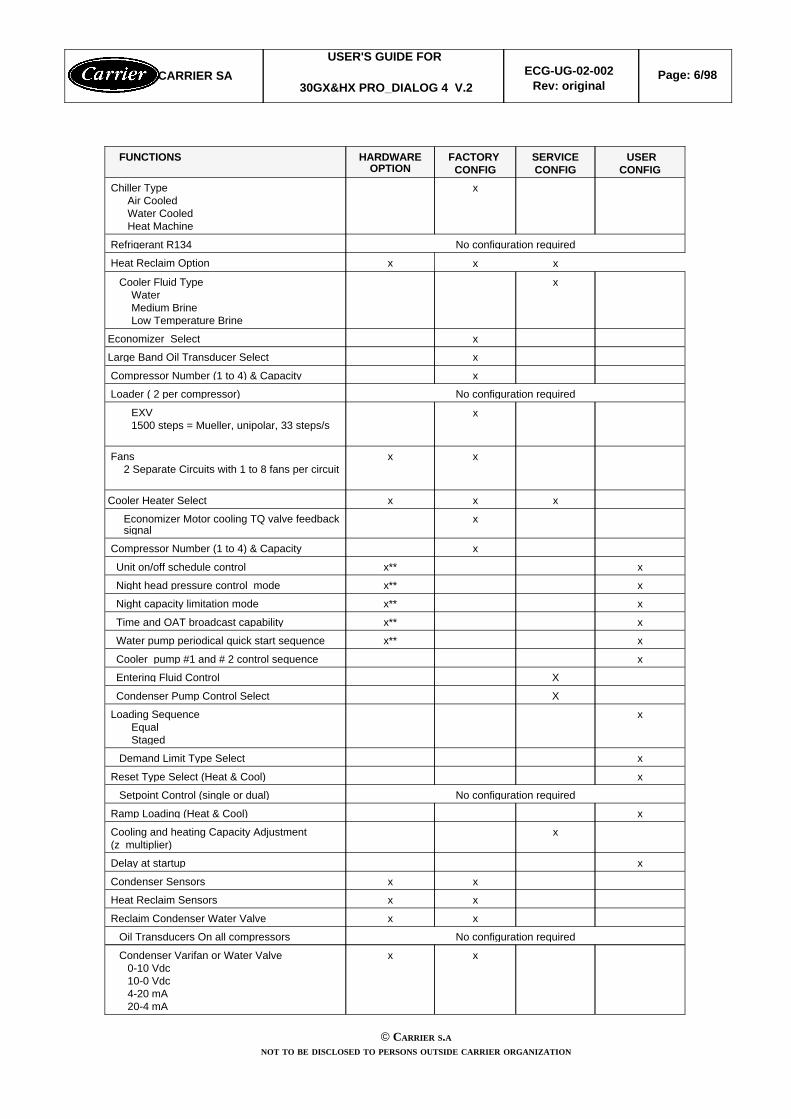
xx Condenser Varifan or Water Valve0-10 Vdc10-0 Vdc4-20 mA20-4 mA
No configuration required Oil Transducers On all compressors
xx Reclaim Condenser Water Valve
xx Heat Reclaim Sensors
xx Condenser Sensors
x Delay at startup
x Cooling and heating Capacity Adjustment (z multiplier)
x Ramp Loading (Heat & Cool)
No configuration required Setpoint Control (single or dual)
x Reset Type Select (Heat & Cool)
x Demand Limit Type Select
x Loading SequenceEqualStaged
XCondenser Pump Control Select
XEntering Fluid Control
xCooler pump #1 and # 2 control sequence
xx**Water pump periodical quick start sequence
xx**Time and OAT broadcast capability
xx**Night capacity limitation mode
xx**Night head pressure control mode
xx**Unit on/off schedule control
x Compressor Number (1 to 4) & Capacity
xEconomizer Motor cooling TQ valve feedbacksignal
xxxCooler Heater Select
xx Fans2 Separate Circuits with 1 to 8 fans per circuit
xEXV1500 steps = Mueller, unipolar, 33 steps/s
No configuration required Loader ( 2 per compressor)
x Compressor Number (1 to 4) & Capacity
xLarge Band Oil Transducer Select
xEconomizer Select
x Cooler Fluid TypeWaterMedium BrineLow Temperature Brine
xxx Heat Reclaim Option
No configuration required Refrigerant R134
x Chiller TypeAir CooledWater CooledHeat Machine
USERCONFIG
SERVICECONFIG
FACTORY CONFIG
HARDWAREOPTION
FUNCTIONS
CARRIER SAUSER'S GUIDE FOR
30GX&HX PRO_DIALOG 4 V.2ECG-UG-02-002
Rev: originalPage: 6/98
© CARRIER S.ANOT TO BE DISCLOSED TO PERSONS OUTSIDE CARRIER ORGANIZATION

xTwo units Master/Slave Control
x FSM & CSM II Control
x Close Control Select
x Maximum Current Override
x Maximum Condensing Temperature Override
USERCONFIG
SERVICECONFIG
FACTORY CONFIG
HARDWAREOPTION
FUNCTIONS
** : require a CCN/Clock boardAll Pro-Dialog controls can work either autonomously or they can be interfaced with the Carrier Comfort Network(CCN). In the later case a communication data cable is used to connect the unit to the CCN communication bus.When Pro-Dialog system operates autonomously it retains all of its own control capabilities but does not offerthe functionality of the CCN network.
2.2 - SOFTWARE REFERENCE NUMBER
This software is referenced under the 15 digits software reference number:
CSA-SR-208410XX
The two last digits (XX) provides the software version (e.g. 2.0).
15 digits reference number can be displayed in the CCN configuration Ctrl_ID table through the BuildingSupervisor, the Network Service Tool or the 30GX&HX Downloader.
Unit Main Interface Configuration Menu allows to display the software version: item #13, user 1 menu.
2.2 - Abbreviations Used
In this manual, the refrigeration circuits are called circuit A and circuit B. The compressors in circuit A arelabeled A1, and A2. Those in circuit B are B1 and B2.
CARRIER SAUSER'S GUIDE FOR
30GX&HX PRO_DIALOG 4 V.2ECG-UG-02-002
Rev: originalPage: 7/98
© CARRIER S.ANOT TO BE DISCLOSED TO PERSONS OUTSIDE CARRIER ORGANIZATION

3 - HARDWARE DESCRIPTION
3.1 - PRODUCT COMPONENT
This control shall employ the following electronic modules:
Basic Board 32 GB 500 182 EENRCP Board 32 GB 500 052 EECCN and RTC Board 32 GB 500 062 EE4 x DO Board (087) OP 12AS 004 EE4xAI - 2xAO Board OP 12AS 005 EE8 x DO Board (Auxiliary 2) 32 GB 500 312 EE8xDO - 4xAI - 2xAO Board (Auxiliary 1) 32 GB 500 322 EEEXV Board 32 GB 500 192 EEScrew Compressor Protection Module 32 GB 500 232 EELocal Interface Device 30GX dual circuits 32 GB 500 092 EE Local Interface Device 30HX dual circuits 32 GB 500 112 EELocal Interface Device 30GX single circuit 32 GB 500 082 EELocal Interface Device 30HX single circuit 32 GB 500 102 EE
This control shall employ the following sensors modules:
Thermistors HH79NZ047C (small size)HH79NZ059C (large size)
Low Pressure Transducer OP12DA040 EEHigh Pressure Transducer OP12DA039 EELarge Band Oil transducer OP12DA057 (for unit operating in low ambient)
CARRIER SAUSER'S GUIDE FOR
30GX&HX PRO_DIALOG 4 V.2ECG-UG-02-002
Rev: originalPage: 8/98
© CARRIER S.ANOT TO BE DISCLOSED TO PERSONS OUTSIDE CARRIER ORGANIZATION

COMPONENT USAGE
1[1]1[1]1[1]1[1]AUX 1 BOARD1[1]1[1]1[1]1[1]4 x AI-2xAO BOARD2[2]2[2]2[2]1PD4 - EXV BOARD
4321PD4 - SCPM BOARD1111PD4 - BASIC BOARD4321
NUMBER OF COMPRESSORSCOMPONENTS
UNIT TYPE : WATER COOLED
2[1]2[1]2[1]1[1]AUX 1 BOARD1[1]1[1]1[1]1[1]4 x AI-2xAO BOARD1[4]1[4]1[4] 1[4]NRCP BASIC BOARD1[3]1[3]1[3]1[3]AUX 2 BOARD (8xDO)1[3]1[3]1[3]2[3]4x DO BOARD2[2]2[2]2[2]1PD4 - EXV BOARD
4321PD4 - SCPM BOARD1111PD4 - BASIC BOARD4321
NUMBER OF COMPRESSORSCOMPONENTS
UNIT TYPE : AIR COOLED - 2 FAN STAGES PER CIRCUIT MAX
1[1]1[1]1[1]1[1]AUX 1 BOARD1[1]1[1]1[1]1[1]4 x AI-2xAO BOARD1[4]1[4]1[4]0NRCP BASIC BOARD1[3]1[3]1[3]1[3]AUX 2 BOARD (8xDO)2[3]2[3]2[3]2[3]4x DO BOARD2[2]2[2]2[2]1PD4 - EXV BOARD
4321PD4 - SCPM BOARD1111PD4 - BASIC BOARD4321
NUMBER OF COMPRESSORSCOMPONENTS
UNIT TYPE : AIR COOLED - MORE THAN 2 FAN STAGES (if no AUX board) or MORETHAN 4 FAN STAGES (AUX BOARD) PER CIRCUIT
1 - additional 4 x AI - 2 x AO board or 8xD0-4xAI-2xAO board required for varifan or reclaim sensors orwater valve option 2 - Second EXV board is required for motor cooling using EXV valve on economizer units3- 4xDO board or 8xDO board is required to control fans. 4xDO is also used to control hot gas bypassvalve on units with single compressor.4-additional NRCP board is required for reclaim option or cooler heater option.
CARRIER SAUSER'S GUIDE FOR
30GX&HX PRO_DIALOG 4 V.2ECG-UG-02-002
Rev: originalPage: 9/98
© CARRIER S.ANOT TO BE DISCLOSED TO PERSONS OUTSIDE CARRIER ORGANIZATION

3.2 - Basic Board
The PD4 - Basic board is 24VAC power supplied. It contains 8 Discrete Inputs (Switch type), 8 Digital Outputs (5triacs and 3 relays), 10 Analog Inputs (five thermistors and four pressure transducers) and 1 analog input (0-10Vdc) . See the schemes in Appendix E. The software is contained in a Flash EPROM (downloadable only withDownloader). All the setpoints, runtime and configuration parameters are contained in an EEPROM (datastorage at power down).
AllSafety Critical Signal (for Contactor Failure)26J3
AllAlarm Circuit B25J3
AllAlarm Circuit A24J3
Air cooledOil Heater Circuit B23J2
Air cooledOil Heater Circuit A22J2
All excepted air cooled withoutreclaim option
Condenser Pump21J2
AllCooler Pump #220J2
AllCooler Pump #119J2
AllCooler pump default18J5
All excepted air cooled withoutreclaim option
Condenser flow switch17J5
AllElectrical box thermostat & network power reversephase detection
16 a & 16 bJ5
AllCooler flow switch & customer interlock (lock_1)15 a & 15 bJ4 & J5
AllDemand limit switch14J4
All excepted heat machineHeat Reclaim switch 13J4
Heat machineHeat Cool switch 13J4
AllDual setpoint switch12J4
AllRemote Control switch status11J4
All0-10 VDC setpoint reset signal or demand limit signal10J8
AllCircuit B suction pressure9J7D
AllCircuit B discharge pressure8J7C
AllCircuit A suction pressure7J7B
AllCircuit A discharge pressure6J7A
Water cooled and heat pumpCondenser entering water temperature5J6
Water cooled and heat pumpCondenser leaving water temperature4J6
Air cooledOutside Temperature 4J6
Master/SlaveMaster/Slave common piping fluid temperature3J6
AllCooling entering water temperature2J6
AllCooling leaving water temperature1J6
UNIT TYPEFUNCTIONCHANNELTERMINAL
3.2 - CCN/Clock Option Board (factory installed)
The PD4 - Global chiller controller has a small option board that can be connected to the Basic Board via asingle 10 pin header and 4 metal standoff. This option board contains one RS-485 driver for CCNcommunication, a real time clock and super cap for two weeks backup. There are two connectors for CCN. Oneis a 3 pin screw connector ( 1= + signal, 2 = ground signal, 3 = - signal) and the other is a 6 pins phone jack.
CARRIER SAUSER'S GUIDE FOR
30GX&HX PRO_DIALOG 4 V.2ECG-UG-02-002
Rev: originalPage: 10/98
© CARRIER S.ANOT TO BE DISCLOSED TO PERSONS OUTSIDE CARRIER ORGANIZATION

3.3 - Screw Compressor Protection Module
This board shall monitor compressor pressure transducer, temperature sensors, oil level, high pressure switch,motor cooling solenoids, oil pumps, motor current, compressor wye-delta startup and compressor protection.
3.3.1 Screw Compressor Module Layout
N.B :Only Y✁✁✁✁ dip switch of the 4 is used to configure start-delta startup procedure (when in ONposition), the 3 others shall remain OFF ! If not, MTA header configuration alarm will occur.
Oil pressure0-5V pressure transducer 44J10BEconomizer pressure0-5V pressure transducer33J10ADischarge Gas Temperature 5K thermistor 22J9Compressor temperature5K thermistor 11J9
Usual FunctionsTypeChannel#AI #*Connector
Current Phase #3Current sensor 3-3J8Current Phase #2Current sensor 2-2J8Current Phase #1Current sensor 1-1J8
Usual FunctionsTypeChannel#CT #*Connector
Oil levelDry contact62J6High PressureDry contact51J7
Main FunctionsTypeChannel#DI #*Connector
Loader #224VAC, 10VATriac118J2Loader #124VAC, 10VATriac107J2
Motor cooling #2 or economizer valve forcircuit which has 2 compressors
24VAC, 10VATriac146J2Motor cooling #124VAC, 26 VATriac135J2Oil solenoid24VAC ,10VATriac124J2Oil pump115VAC,145VA,-Triac93J4Compressor output “Y”115VAC, 70VA,Relay/TRiac82J3Compressor output “D”115VAC, 250VARelay/Triac71J3
Main FunctionsLoad max(Voltage,power)
TypeChannel#DO #*Connector
CARRIER SAUSER'S GUIDE FOR
30GX&HX PRO_DIALOG 4 V.2ECG-UG-02-002
Rev: originalPage: 11/98
© CARRIER S.ANOT TO BE DISCLOSED TO PERSONS OUTSIDE CARRIER ORGANIZATION

3.3.2- Compressor Part Number / MTA header configuration
0 0 0 1 0 1 0 192 3906NW2146S7N0 0 0 1 1 1 1 1112 4606NW2174S7N0 0 1 0 1 0 1 1136 5606NW2209S7N0 1 0 0 1 0 1 0198 8006NW2300S7N
0 0 1 0 0 0 0 0114 3906NA2146S7N0 0 1 1 1 0 0 1164 6606NW2250S7N0 0 1 0 1 1 1 0142 4606NA2174S7N0 0 1 1 1 1 0 0170 5606NA2209S7N0 1 0 1 0 1 0 0218 8006NW2300S5E0 1 0 0 1 1 0 1204 6606NA2250S7N0 1 0 1 1 1 1 1240 8006NA2300S5N0 1 1 1 1 1 0 0298 8006NA2300S5E
Compressor MTA Header ConfigMSB(8 . . . . . . . 1) LSB
MTA (for 400V)
TonsCompressor phase 3 Part Number
3.1.4 - 4xDO BOARDThe 4xDO board has 4 digital outputs capable of switching 24 VAC at 1 amp numbered from 1 to 4 on connectorJ4. They have a common point numbered 12 on connector J4. D0 #1 and Do # 2 shall support 1 fanD0 #3 shall support 1 fan if circuit has less than 5 fans. It shall support 2 fans if circuit has more than 4 fans. D0 #4 shall support 1 fan if circuit has less than 6 fans. It shall support
2 fans if circuit has 6 fans.3 fans if circuit has 7 fans.4 fans if circuit has 8 fans.
3.1.4.2 - Terminal J4 Description
12121212 1212121211111111
DO #4DO #4DO #4DO #4
DO #3DO #3DO #3DO #3
DO #2DO #2DO #2DO #2
DO #1DO #1DO #1DO #1
24 VAC DO24 VAC DO24 VAC DO24 VAC DOPOWER SUPPLYPOWER SUPPLYPOWER SUPPLYPOWER SUPPLY
TRIACTRIACTRIACTRIAC
TRIACTRIACTRIACTRIAC
TRIACTRIACTRIACTRIAC
TRIACTRIACTRIACTRIAC
TO CONTACTOR # 1TO CONTACTOR # 1TO CONTACTOR # 1TO CONTACTOR # 1
TO CONTACTOR # 2TO CONTACTOR # 2TO CONTACTOR # 2TO CONTACTOR # 2
TO CONTACTOR #3 (or and #4)TO CONTACTOR #3 (or and #4)TO CONTACTOR #3 (or and #4)TO CONTACTOR #3 (or and #4)
TO OTHER CONTACTORSTO OTHER CONTACTORSTO OTHER CONTACTORSTO OTHER CONTACTORS
pins 12 are connected togetherpins 12 are connected togetherpins 12 are connected togetherpins 12 are connected together
4444 3333 2222 1111 TERMINAL J4TERMINAL J4TERMINAL J4TERMINAL J4
CARRIER SAUSER'S GUIDE FOR
30GX&HX PRO_DIALOG 4 V.2ECG-UG-02-002
Rev: originalPage: 12/98
© CARRIER S.ANOT TO BE DISCLOSED TO PERSONS OUTSIDE CARRIER ORGANIZATION

3.1.5 - AUX Boards 3.1.5.1 - General
R
S V
CH 4
J7
CH 1
--
R
S V
--
J2
--
CH
13
75 mm(2.95in)
CH 3
J4
CH 2
PD4-AUX1
--------
32GB 500 322 EE
-- G
+
12
STATUS
--
TPV
CH13
CEPL130487-01
J3
CH 12
J124VAC
--
------
SIO
J9
143 mm ( 5.60 in )
SIO
CH 11
--
11
CH 10
--
J5
TPV
CH14
l
3
2
1
--
3
2
1
CH 8
--
-- G
+
CH 7
--J6
CH
14
CH 6
l
--
J8
CH 5
CH 9
The AUX1 board shall allow:w the control of 1 to 8 fan stages;w the monitoring of 4 temperatures or 2 temperatures and 2 pressures.w the control of 2 Varifan or two water valves
The AUX2 board shall allow:w the control of 1 to 8 fan stages.
Discrete outputs requirements: AUX1 and AUX2
Fan 8 - circuit A , 4 or 8 circuit B88
Fan 7 - circuit A , 3 or 7 circuit B/Reclaim option,condenser heater
77Fan 6 - circuit A , 2 or 6 circuit B66Fan 5 - circuit A, 1 or 5 circuit B/ Reclaim valve B55
J3
Fan 4 - circuit A or circuit B/ Pumpdown valve B44Fan 3 - circuit A or circuit B33Fan 2 - circuit A or circuit B/ Reclaim valve A 22Fan 1 - circuit A or circuit B/ Pumpdown valve A 11
J2
AUX1&
AUX2
Main FunctionsChannel#DO #ConnectorBoard
All are standard 24 VAC/±10%. All 24Vac common ground must be connected together on board and to 24Vacground pin of J1. All DO’s total consomption = 115VA
CARRIER SAUSER'S GUIDE FOR
30GX&HX PRO_DIALOG 4 V.2ECG-UG-02-002
Rev: originalPage: 13/98
© CARRIER S.ANOT TO BE DISCLOSED TO PERSONS OUTSIDE CARRIER ORGANIZATION

3.1.6 - EXV BOARD
The EXV board shall be able to control 2 EXV’s and 2 thermistors.
Analog inputs requirements
Economizer Motor Cooling TQ Valve Feedback Signal Circuit B5/10 K thermistor2J3 (TH B)Economizer Motor Cooling TQ Valve Feedback Signal Circuit A5/10 K thermistor1J3 (TH A)
Usual FunctionsTypeAI#*
Connector
Discrete output requirements
The EXV board shall be able to drive both unipolar and bipolar stepper motors via a common connector. Thedefault configuration shall be unipolar, 30 steps/s step rates and 1500 steps range such as to allow easy retrofitwith Pro-Dialog phase 1, 2 and 3 units fitted with Mueller Brass EXV’s. It shall be able to handle 12V @ 0.5 A percoil and maintain a step rate of at least 200 steps per second (unipolar or bipolar).
Note: board shall be able to handle a total coil load of 1 Amp for unipolar and 2 Amps for bipolar.Connection to the EXV shall be done through two Molex, 5 pin, 3.91 pitch (one per EXV) [J2A & J2B].
12VDC (for unipolar stepper motor)Coil 4Coil 3Coil 2Coil 154321
Connector J2A & J2B - Pins description
3.1.7 - 4xAI-2xAO BOARD
This board provides 4 analog inputs (labeled AI #1, AI #2, AI #3, and AI #4 on the terminal J2) and 2 analogoutputs (labeled AO #1 and AO #2 on the terminal J1). It allows to use the following features:
w Optional reclaim thermistors when reclaim option is not used
w Remote discharge transducer on remote condenser on split units.
w Optional varifan on air cooled units or water valve on water cooled units
Each input can be independently configured with a bridge allowing to close 3 pair of pins named T,C or V.
V: Transducers 5 Volts power supply1: SignalR: -
V - 1 - RPressure transducer(remote dischargepressure circuit B)
V
Carrier thermistor: HH 79NZ 047, 5K@ 25°C1 - RunusedT,C
AI #2
V: Transducers 5 Volts power supply1: SignalR: -
V - 1 - RPressure transducer(remote dischargepressure circuit A)
V
unused1 - RunusedT,C
AI #1
REMARKSPINSFUNCTIONBRIDGEPOSITION
ANALOGINPUT
J2
CARRIER SAUSER'S GUIDE FOR
30GX&HX PRO_DIALOG 4 V.2ECG-UG-02-002
Rev: originalPage: 14/98
© CARRIER S.ANOT TO BE DISCLOSED TO PERSONS OUTSIDE CARRIER ORGANIZATION

1: +R: -
1 - RunusedC
V: Transducers 5 Volts power supply1: SignalR: -
V - 1 - Rnot usedV
Carrier thermistor: HH 79NZ 047, 5K@ 25°C1 - RReclaim enteringthermistor
T
AI #4
1: +R: -
1 - RunusedC
V: Transducers 5 Volts power supply1: SignalR: -
V - 1 - Rnot usedV
Carrier thermistor: HH 79NZ 047, 5K@ 25°C1 - RReclaim leavingthermistor
T
AI #3
REMARKSPINSFUNCTIONBRIDGEPOSITION
ANALOGINPUT
J2
Each output can be independently configured with a bridge allowing to close 2 pair of pins named C or V.
6: + R: -
6 - R4 - 20 mA Varifancircuit B
C
6: + R: -
6 - R0-10 Vdc Varifan circuitB
V
AO #2
5: + R: -
5 - R4 - 20 mA Varifancircuit A or water valve
C
5: + R: -
5 - R0- 10 Vdc Varifan circuitA or water valve
V
AO #1
REMARKSPINSFUNCTIONBRIDGEPOSITION
ANALOGOUTPUT
J1
CARRIER SAUSER'S GUIDE FOR
30GX&HX PRO_DIALOG 4 V.2ECG-UG-02-002
Rev: originalPage: 15/98
© CARRIER S.ANOT TO BE DISCLOSED TO PERSONS OUTSIDE CARRIER ORGANIZATION
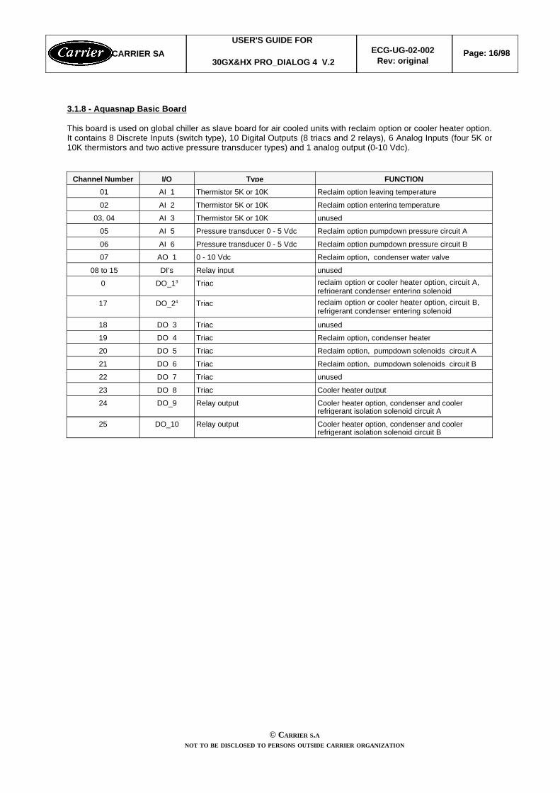
3.1.8 - Aquasnap Basic Board
This board is used on global chiller as slave board for air cooled units with reclaim option or cooler heater option.It contains 8 Discrete Inputs (switch type), 10 Digital Outputs (8 triacs and 2 relays), 6 Analog Inputs (four 5K or10K thermistors and two active pressure transducer types) and 1 analog output (0-10 Vdc).
Cooler heater option, condenser and coolerrefrigerant isolation solenoid circuit B
Relay outputDO_1025
Cooler heater option, condenser and coolerrefrigerant isolation solenoid circuit A
Relay outputDO_924
Cooler heater outputTriacDO 823
unusedTriacDO_722
Reclaim option, pumpdown solenoids circuit BTriacDO 621
Reclaim option, pumpdown solenoids circuit ATriacDO_520
Reclaim option, condenser heater TriacDO 419
unusedTriacDO 318
reclaim option or cooler heater option, circuit B,refrigerant condenser entering solenoid
TriacDO_2417
reclaim option or cooler heater option, circuit A,refrigerant condenser entering solenoid
TriacDO_130
unusedRelay inputDI’s 08 to 15
Reclaim option, condenser water valve0 - 10 VdcAO_1 07
Reclaim option pumpdown pressure circuit B Pressure transducer 0 - 5 VdcAI 6 06
Reclaim option pumpdown pressure circuit APressure transducer 0 - 5 VdcAI_5 05
unusedThermistor 5K or 10KAI 3 03, 04
Reclaim option entering temperatureThermistor 5K or 10KAI 2 02
Reclaim option leaving temperatureThermistor 5K or 10KAI_1 01FUNCTIONTypeI/OChannel Number
CARRIER SAUSER'S GUIDE FOR
30GX&HX PRO_DIALOG 4 V.2ECG-UG-02-002
Rev: originalPage: 16/98
© CARRIER S.ANOT TO BE DISCLOSED TO PERSONS OUTSIDE CARRIER ORGANIZATION

3.2 - Pressure sensors
They are used to measure in each circuit :
w Discharge gas pressure
w Suction pressure
w Economizer pressure
and in each compressor :
w Oil pressure
w Economizer pressure on first compressor and also in the second compressor if unit is not equippedwith economizer
They are electronic sensors which linearise the output signal and deliver a 0 to 5 Vdc to either the basic board orto an analog board. Three types of sensors are used.
3.2.1 - High pressure side sensors
They are used to measure discharge pressure and oil pressures when large band oil pressure transducer is notselected. Carrier part: OP12DA039
High pressure side transducer curve
3.2.2 - Large band pressure sensors
They are used to measure oil pressures for unit operating with low ambient (when large band oil pressuretransducer is selected). Carrier part: OP12DA057
Large band oil pressure transducer curve
CARRIER SAUSER'S GUIDE FOR
30GX&HX PRO_DIALOG 4 V.2ECG-UG-02-002
Rev: originalPage: 17/98
© CARRIER S.ANOT TO BE DISCLOSED TO PERSONS OUTSIDE CARRIER ORGANIZATION
50 100 150 200 250 450 500689 2068 2414 31032758
4
2
0
Vol
tage
(V
DC
)V
olta
ge (
VD
C)
Vol
tage
(V
DC
)V
olta
ge (
VD
C)
kPaPSI
3
1
5
34471724345 1034
PressurePressurePressurePressure
1379350300 400
-6.6 100 155 420 5001904 2252 28952670
4
2
Vol
tage
(V
DC
)V
olta
ge (
VD
C)
Vol
tage
(V
DC
)V
olta
ge (
VD
C)
kPaPSI
3
1
5
34471484-45 689
PressurePressurePressurePressure
1068 327276 38750
345 215

3.2.3 - Suction Pressure and Economizer Pressure sensors
These are in the low pressure side. Suction pressure transducer takes the place of the low pressure switches,low pressure gauges and the low pressure safety switch (where these are usually fitted). Economizer pressure isused to measure the intermediary pressure between low and high pressure. The oil pressure is subtracted fromthis pressure to determine the oil differential pressure for oil pressure safety purpose.
Carrier part: OP12DA040
Low pressure transducer curve
3.3 - THERMISTORS
All thermistor, excepted the reset sensor, have similar characteristics (see next page). They have Carrier Part No. HH 79 NZ 047
3.3.1 - Discharge gas temperature
This is installed on the discharge pipe of each compressor. It is used to control the discharge superheat. Thedischarge gas temperature (lowest discharge compressor temperature or average discharge temperature of bothcompressors) is subtracted to the saturated condensing temperature to determine the discharge superheat.
CARRIER SAUSER'S GUIDE FOR
30GX&HX PRO_DIALOG 4 V.2ECG-UG-02-002
Rev: originalPage: 18/98
© CARRIER S.ANOT TO BE DISCLOSED TO PERSONS OUTSIDE CARRIER ORGANIZATION
20 40 60 80 100 180 200
276 828 965 12411103
4
2
0
Vol
tage
(V
DC
)V
olta
ge (
VD
C)
Vol
tage
(V
DC
)V
olta
ge (
VD
C)
kPa
PSI
3
1
5
1379689138 414
PressurePressurePressurePressure
552
140120 160

5K Resistor: Resistance vs Temperature Curve
602,480,01 694,052,05 203,224,020 075,9-4,0612,679,51 725,151,55 321,223,520 606,4-4,5
285,2107,0623,279,01 756,851,05 442,223,021 152,6-5,0292,1106,5634,078,51 789,150,55 566,422,521 715,7-5,5298,6106,0645,278,01 822,150,05 693,922,022 295,6-6,0305,3105,5656,877,51 855,749,55 824,621,522 893,2-6,5311,6105,0668,677,01 890,149,05 958,721,023 509,0-7,0317,9104,5680,876,51 925,148,56 096,320,524 143,6-7,5323,8104,0693,376,01 960,948,06 237,520,024 797,8-8,0329,7103,5706,175,51 997,447,56 382,319,525 472,2-8,5335,3103,0719,275,02 034,747,06 530,919,026 167,5-9,0341,1102,5732,674,52 072,846,56 683,418,526 884,4-9,5346,3102,0746,574,02 111,746,06 839,818,027 623,8-10,0351,5101,5760,673,52 151,545,57 000,317,528 386,3-10,5356,7101,0775,073,02 192,245,0 7164.917,029 172,7-11,0361,6100,5789,872,52 233,844,57 333,916,529 984,0-11,5366,5100,0804,872,02 276,344,07 507,216,030 821,0-12,0371,199,5820,271,52 319,943,57 685,115,531 684,6-12,5375,899,0836,071,02 364,443,07 867,715,032 575,6-13,0380,398,5952,070,52 410,042,58 055,014,533 495,2-13,5384,798,0868,470,02 456,642,08 247,214,034 444,2-14,0389,097,5885,169,52 504,441,58 444,513,535 423,7-14,5393,397,0902,169,02 553,341,08 469,913,036 434,7-15,0397,696,5919,468,52 603,440,5 8854.712,537 478,4-15,5401,896,0937,168,02 654,740,0 9068.012,038 555,9-16,0406,095,5955,167,52 707,239,5 9287.011,539 668,3-16,5410,395,0973,467,02 761,139,09 511,711,040 816,9-17,0414,594,5992,166,52 816,238,5 9742.510,542 002,9-17,5418,894,01 011,066,02 872,838,0 9979.310,043 227,6-18,0423,093,51 030,365,52 930,737,510 222,6 9.544 492,4-18,5427,493,01 050,065,02 990,137,010 472,3 9.045 798,6-19,0431,892,51 069,964,53 051,036,510 728,88,547 147,7-19,5436,392,01 090,264,03 113,436,010 992,18,048 541,1-20,0440,991,51 110,963,53 177,535,511 262,77,549 980,4-20,5445,791,01 131,863,03 243,135,011 540,5 7.051 467,0-21,0450,690,51 153,262,53 310,434,511 826,0 6.553 002,7-21,5455,690,01 174,862,03 379,434,012 119,26,054 589,1-22,0460,889,51 196,961,53 450,233,512 420,55,556 227,9-22,5466,189,01 219,361,03 522,933,012 730,15,057 920,9-23,0571,688,51 242,160,53 597,332,513 048,3 4.559 670,0-23,5477,488,01 265,260,03 673,732,013 375,34,061 476,9-24,0483,287,51 288,759,53 752,131,513 711,43,563 343,7-24,5489,487,01 312,659,03 832,531,014 056,9 3.065 272,4-25,0495,786,51 336,958,53 915,030,514 412,2 2.567 265,0-25,5502,386,01 361,658,03 999,630,014 777,52,069 323,7-26,0509,285,51 386,857,54 086,329,515 153,1 1.571 450,6-26,5516,285,01 412,357,04 175,429,015 539,51,073 648,0-27,0523,684,51 438,356,54 266,728,515 936,90,575 918,3-27,5531,284,01 464,756,04 630,428,016 345,70,078 263,9-28,0539,183,51 491,655,54 456,627,516 766,3-0,580 687,1-28,5547,283,01 519,055,04 555,227,017 199,1-1,083 190,7-29,0555,782,51 546,954,54 656,426,517 644,5-1,585 777,0-29,5564,482,01 575,254,04 760,226,018 102,9-2,088 449,0-30,0573,481,51 604,153,54 866,825,518 574,8-2,591 209,3-30,5582,881,01 633,553,04 976,025,019 060,6-3,094 060,8-31,0592,480,51 663,552,55 088,124,519 560,8-3,597 006,4-31,5602,480,01 694,052,05 203,224,020 075,9-3,5100 049,0-32,0
(OHMS)(°C)(OHMS)(°C)(OHMS)(°C)(OHMS)(°C)(OHMS)(°C)
Resistance
Temp.Resistance
Temp.Resistance
Temp.Resistance
Temp.Resistance
Temp.
CARRIER SAUSER'S GUIDE FOR
30GX&HX PRO_DIALOG 4 V.2ECG-UG-02-002
Rev: originalPage: 19/98
© CARRIER S.ANOT TO BE DISCLOSED TO PERSONS OUTSIDE CARRIER ORGANIZATION

4.2 - CONFIGURATION4.2.1 - GeneralFour types of configuration are available:
w The factory configuration. It describes the "hardware" structure of the unit (e.g. the number of compressors,valve...). This configuration is accessible through the Main Interface Factory menu Menus or the NetworkService Tool and can be done by Carrier factory or service only.
w The Service configuration. It allows to modify operating parameters. This configuration is accessiblethrough the Main Interface Service Menus or the Network Service Tool and can be done by Carrierfactory or service only.
w The User configuration. It allows to modify a limited number of simple parameters (i.e. loading sequence,start-up delay, cooler pumps control, reset select...). This configuration can be done through the MainInterface or through the Network Service Tool. This configuration can be modified by the customer.
w The network configuration. It allows to modify parameters used by network functions (i.e. Alarm POC,Broadcast ...). This is accessible through the Building Supervisor or the Network Service Tool.
4.2.2 -Main interface configuration sub menu tree structure
‘broAdCASt’’7S‘’HoLidAY’’6M‘’SCHEduLE 2’’5E
‘’MAStEr SLAvE’’‘’SCHEduLE 1’’4T‘’SErViCE 3’’‘’dAtE’’3I
"FACtorY 2 MEnu"‘’SErViCE 2’’‘’USEr 2’’2"FACtorY 1 MEnu"‘’SErViCE 1’’‘’USEr 1’’1"FACtorY MEnu"‘’SErViCE MEnu’’‘’USEr MEnu’’0
FACTORYSERVICEUSERCONFIGURATION SUB MENUS
MAIN INTERFACE FACTORY CONFIGURATION SUB MENU TREE STRUCTURE
TQ_r_fbk (TQ valve feeddback)19pd4_aux (aux board select)18
exvb max (1500)17exva max (1500)16
heat sel (idem version 1.x)15cira lwt (idem version 1.x)14
evap_pas (idem version 1.x)13recl_opt (idem version 1.x)12hr temp (idem version 1.x)11
cpb2 mta (idem version 1.x)10cpb1 mta (idem version 1.x)9cpa2 mta (idem version 1.x)8cpa1_mta (idem version 1.x)7S
oil_sel (idem version 1.x)6Mecon sel (idem version 1.x)5Ehd selec (idem version 1.x)4Tnb fan b (idem version 1.x)3Inb fan a (idem version 1.x)2
fac_passunit_typ (idem version 1.x)1"FACtorY2 MEnu""FACtorY1 MEnu"0
FACTORY 2FACTORY 1FACTORY CONFIGURATION SUB-SUB MENUS
© CARRIER S.ANOT TO BE DISCLOSED TO PERSONS OUTSIDE CARRIER ORGANIZATION
CARRIER SAUSER'S GUIDE FOR
30GX&HX PRO_DIALOG 4 V.2 ECG - UG - 02 - 02
Rev: OriginalPage: 20 /98

4.2.3 - Factory configuration4.2.3.1 - Factory configuration from Service Tool
The Network Service tool allows to view and modify the factory configuration (table FACTORY in 'ModifyController').
TABLE NAME: FACTORY PIC TABLE TYPE : 10H, instance 1
DESCRIPTION STATUS DEFAULT UNITS POINT
1 Chiller Type 1,2,31 1 - unit_typ2 Circuit A Fan Stages Num 0 to 82 0 - nb_fan_a3 Circuit B Fan Stages Num 0 to 82 0 - nb_fan_b4 Varifan or W. Valves Sel 0/1/2/3/4 0 - hd_selec5 Economizer Select Yes/No3 No - econ_sel6 Large Bd Oil Transducers Yes/No4 No - oil_sel7 Comp A1 Must Trip Amps 0 to 5605 0 - mta_cpa18 Comp A2 Must Trip Amps 0 to 5605 0 - mta_cpa29 Comp B1 Must Trip Amps 0 to 5605 0 - mta_cpb110 Comp B2 Must Trip Amps 0 to 5605 0 - mta_cpb211 Reclaim Sensor Select Yes/No6 No - hr_tmp12 Air Cooled Reclaim Sel Yes/No7 No - recl_opt13 Evaporator Number Pass 1 to 38 3 - evap_pas14 Cooler LWT On Circuit A Yes/No9 Yes - cira_lwt15 Cooler Heater Select Yes/No10 No - heat_sel16 Factory Password 0 to 15011 113 - fac_pass17 EXV A Maximum Steps Numb 1500/1500012 1500 - exva_max18 EXV B Maximum Steps Numb 1500/1500012 1500 - exvb_max19 Motor Cool. TQ Feedback Yes/No13 No - TQ_r_fbk20 PD4 Aux Boards Select Yes/No14 No - pd4_aux
Parameters from 1 to 16 in version 1.x are the same than those in the new version 2.X.
For Retrofit from verson 1.x to the new 2.x, it is better to write down in a paper, configuration items from 1 to 16. Use Service Tool to upload all the configuration from version 1 (example address 1).Then use address search function to change the address to 2 before downloading the new softwareversion 2.x. Use Service Tool to add a new controller with a different addresse (example address 1 forversion 1 and address 2 for version 2). Once Upload configuration is done, fill factory configuration inFACTORY table and then download this.
1. 1 = air cooled. 2 = water cooled . 3 = heat machine2. 0 = no fan
< 4 = each DO output of the 4xDO board support 1 fan . > 5 = DO # 1 and DO # 2 support 1 fan each. DO # 3 support 2 fans DO # 4 support 1 fan if circuit has 5 fans max
DO # 4 support 2 fans if circuit has 6 fans max DO # 4 support 3 fans if circuit has 7 fans max DO # 4 support 4 fans if circuit has 8 fans max
nb : these fans are not controlled by a varifan. For pro_dialog 4 Auxiliary board select, each DO output of the Auxiliary board support 1 fan
© CARRIER S.ANOT TO BE DISCLOSED TO PERSONS OUTSIDE CARRIER ORGANIZATION
CARRIER SAUSER'S GUIDE FOR
30GX&HX PRO_DIALOG 4 V.2 ECG - UG - 02 - 02
Rev: OriginalPage: 21 /98
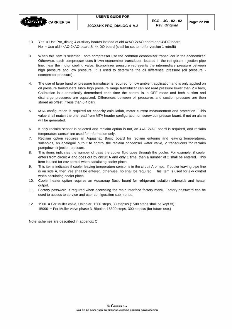
13. Yes = Use Pro_dialog 4 auxiliary boards instead of old 4xAO-2xAO board and 4xDO boardNo = Use old 4xAO-2xAO board & 4x DO board (shall be set to no for version 1 retrofit)
3. When this item is selected, both compressor use the common economizer transducer in the economizer.Otherwise, each compressor uses it own economizer transducer, located in the refrigerant injection pipeline, near the motor cooling valve. Economizer pressure represents the intermediary pressure betweenhigh pressure and low pressure. It is used to determine the oil differential pressure (oil pressure -economizer pressure).
4. The use of large band oil pressure transducer is required for low ambient application and is only applied onoil pressure transducers since high pressure range transducer can not read pressure lower than 2.4 bars,Calibration is automatically determined each time the control is in OFF mode and both suction anddischarge pressures are equalized. Differences between oil pressures and suction pressure are thenstored as offset (if less than 0.4 bar).
5. MTA configuration is required for capacity calculation, motor current measurement and protection. Thisvalue shall match the one read from MTA header configuration on screw compressor board, if not an alarmwill be generated.
6. If only reclaim sensor is selected and reclaim option is not, an 4xAI-2xAO board is required, and reclaimtemperature sensor are used for information only.
7. Reclaim option requires an Aquasnap Basic board for reclaim entering and leaving temperatures,solenoids, an analogue output to control the reclaim condenser water valve, 2 transducers for reclaimpumpdown injection pressure.
8. This items indicates the number of pass the cooler fluid goes through the cooler. For example, if coolerenters from circuit A and goes out by circuit A and only 1 time, then a number of 2 shall be entered. Thisitem is used for exv control when caculating cooler pinch.
9. This items indicates if cooler leaving temperature sensor is in the circuit A or not. If cooler leaving pipe lineis on side A, then Yes shall be entered, otherwise, no shall be required. This item is used for exv controlwhen caculating cooler pinch.
10. Cooler heater option requires an Aquasnap Basic board for refrigerant isolation solenoids and heateroutput.
11. Factory password is required when accessing the main interface factory menu. Factory password can beused to access to service and user configuration sub menus.
12. 1500 = For Muller valve, Unipolar, 1500 steps, 33 steps/s (1500 steps shall be kept !!!)15000 = For Muller valve phase 3, Bipolar, 15300 steps, 300 steps/s (for future use,)
Note: schemes are described in appendix C.
© CARRIER S.ANOT TO BE DISCLOSED TO PERSONS OUTSIDE CARRIER ORGANIZATION
CARRIER SAUSER'S GUIDE FOR
30GX&HX PRO_DIALOG 4 V.2 ECG - UG - 02 - 02
Rev: OriginalPage: 22 /98

4.2.3.2- Factory configuration from main interface
Economizer units with TQ feedback signal sensor-yes/notq r fbk19
Pro dialog 4 Aux boards select -yes/nopd4 aux18
EXV A Maximum Steps Number (Shall be left 1500)-1500 to 15000exva_max17
EXV A Maximum Steps Number (Shall be left 1500)-1500 to 15000exva_max16
Cooler heater select displayed on air cooled chiller only-yes/noheat sel15[1]
Cooler leaving sensor on circuit A select-yes/nocira lwt14
Cooler number of pass select-1 to 3evap pas13
Heat reclaim option select-yes/norecl opt12[1]
Reclaim sensors select-yes/nohr_temp11[1]
Compressor B2 Must Trip Amps. amps0 to 560cpb2_mta10[1]
Compressor B1 Must Trip Amps. amps0 to 560cpb1 mta9[1]
Compressor A2 Must Trip Amps. amps0 to 560cpa2 mta8[1]
Compressor A1 Must Trip Amps amps0 to 560cpa1 mta7
Large Band Oil transducer select-yes/nooil sel6
Economizer select-yes/noecon_sel5
Varifan or Water valve select-0,1,2,3,4hd_selec4
Number of fans on circuit B not controlled by a varifan -0 to 8nb fan b3[1]
Number of fans on circuit A not controlled by a varifan -0 to 8nb fan a2[1]
Chiller type select-1/2,3,4unit typ1
When selected this item shall allow to return to the Configurationmain menu.
-"FACTORYMEnu"
-0COMMENTSUNITSFORMATVARIABLEITEM #
Factory password-0 to 150fac_pass1
When selected this item shall allow to return to the Configurationmain menu.
-"FACTORY 2MEnu"
-0COMMENTSUNITSFORMATVARIABLEITEM #
© CARRIER S.ANOT TO BE DISCLOSED TO PERSONS OUTSIDE CARRIER ORGANIZATION
CARRIER SAUSER'S GUIDE FOR
30GX&HX PRO_DIALOG 4 V.2 ECG - UG - 02 - 02
Rev: OriginalPage: 23 /98

Economizer Tq valve Feedback Signal Control Wiring
© CARRIER S.ANOT TO BE DISCLOSED TO PERSONS OUTSIDE CARRIER ORGANIZATION
CARRIER SAUSER'S GUIDE FOR
30GX&HX PRO_DIALOG 4 V.2 ECG - UG - 02 - 02
Rev: OriginalPage: 24 /98
TQ output (done)
TQ output (done)SCPM A1
SCPM B1
THA
THB
EXV BOARD
Connexion to be done (tq_r_fbk = yes)

4.2.4 - Service configuration
4.2.4.1 - Service1 configuration table from Service Tool
The Network Service tool allows to view and modify the service configuration table SERVICE1. Unit shall bestopped and under CCN Operating Type control.
TABLE NAME: SERVICE1 PIC TABLE TYPE : 13H, instance 1
DESCRIPTION STATUS DEFAULT UNITS POINT
1 Cooler Fluid Type 1/2/31 1 - flui_typ2 Head Pressure Diff Timer 10 to 1202 90 sec head_tim3 Head Pressure Diff 3.8 to 223 5 ^C head_dif4 Prop PID Gain Varifan/Wv -20.0 to 20.04 1.0 - hd_pg5 Int PID Gain Varifan/Wv -5.0 to 5.04 1.0 - hd_ig6 Deri PID Gain Varifan/Wv -20.0 to 20.04 1.0 - hd_dg7 Cir A Superheat Setpoint 8.3 to 225 11 ^C dsh_sp_a8 Cir B Superheat Setpoint 8.3 to 225 11 ^C dsh_sp_b9 Cir A Cooler Pinch Setpt 0.5 to 2.66 1.0 ^C pinc_p_a10 Cir B Cooler Pinch Setpt 0.5 to 2.66 1.0 ^C pinc_p_b11 Maximum Condensing Temp 48.8 to 71.17 68 °C mct_sp12 Max Condensing Temp Diff 5.5 to 117 6.7 ^C mct_diff13 Maximum Current Setpoint 50 to 858 80 % curr_max14 Maximum Current Diff 5 to 208 10 % curr_dif15 Close Capacity Ctrl Sel Dsable/Enable9 Dsable - cls_ctrl16 Auto Z Multiplier Setpt 4 to 610 6 - zm_spt17 Maximum Z Multiplier 1.0 to 6.011 6.0 - hc_zm18 Entering Fluid Control Yes/No12 No - ewt_opt
Note: this table canl be downloadable at any time. However, modified value shall not be used by tasks until theunit is in off state . This shall not apply to the Varifan/water valves gains that shall be modified at any time andused immediately by the head pressure control tasks even if the unit is in operation.
1. > 1 = Water2 = Brine3 = Low Brine
Warning: This decision affects the freeze protection threshold.w water: 1.1°Cw brine & low brine: coldest setpoint - 4.4°C
2. Used to set fan cycling. Decreasing this value will increase fan cycling. This timer can be reduced since theunit is fitted with an important number of fan stages, as to increase the condensing control accuracy. But incertain cases, notably on units with few fan stages, at too small value can causes superheat huntingproblems.
3. Used to set fan cycling. Default value is 5 ^C, 11.1^C or higher value are recommanded if unit has varifan.This value can be increased on units with few fan stages to avoid superheat hunting problems.
© CARRIER S.ANOT TO BE DISCLOSED TO PERSONS OUTSIDE CARRIER ORGANIZATION
CARRIER SAUSER'S GUIDE FOR
30GX&HX PRO_DIALOG 4 V.2 ECG - UG - 02 - 02
Rev: OriginalPage: 25 /98
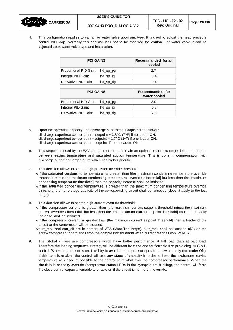
4. This configuration applies to varifan or water valve upon unit type. It is used to adjust the head pressurecontrol PID loop. Normally this decision has not to be modified for Varifan. For water valve it can beadjusted upon water valve type and installation.
0.4hd_sp_dgDerivative PID Gain:0.4hd_sp_igIntegral PID Gain:2.7 hd_sp_pgProportional PID Gain:
Recommanded for aircooled
PDI GAINS
2.0hd_sp_dgDerivative PID Gain:0.2hd_sp_igIntegral PID Gain:2.0 hd_sp_pgProportional PID Gain:
Recommanded forwater cooled
PDI GAINS
5. Upon the operating capacity, the discharge superheat is adjusted as follows : discharge superheat control point = setpoint + 3.8^C (7^F) if no loader ON.discharge superheat control point =setpoint + 1.7^C (3^F) if one loader ON.discharge superheat control point =setpoint if both loaders ON.
6. This setpoint is used by the EXV control in order to maintain an optimal cooIer exchange delta temperaturebetween leaving temperature and saturated suction temperature. This is done in compensation withdischarge superheat temperature which has higher priority.
7. This decision allows to set the high pressure override threshold:w If the saturated condensing temperature is greater than [the maximum condensing temperature override
threshold minus the maximum condensing temperature override differential] but less than the [maximumcondensing temperature threshold] then the capacity increase shall be inhibited.
w If the saturated condensing temperature is greater than the [maximum condensing temperature overridethreshold] then one stage capacity of the corresponding circuit shall be removed (doesn't apply to the laststage).
8. This decision allows to set the high current override threshold:w If the compressor current is greater than [the maximum current setpoint threshold minus the maximum
current override differential] but less than the [the maximum current setpoint threshold] then the capacityincrease shall be inhibited.
w If the compressor current is greater than [the maximum current setpoint threshold] then a loader of thecircuit or the compressor will be stopped.
w curr_max and curr_dif are in percent of MTA (Must Trip Amps). curr_max shall not exceed 85% as thescrew compressor board shall stop the compressor for alarm when current reaches 85% of MTA.
9. The Global chillers use compressors which have better performance at full load than at part load.Therefore the loading sequence strategy will be different from the one for flotronic II or pro-dialog 30 G & Hcontrol. When compressor is on, it will try to avoid the compressor operate at low capacity (no loader ON).If this item is enable, the control will use any stage of capacity in order to keep the exchanger leavingtemperature as closed at possible to the control point what ever the compressor performance. When thecircuit is in capacity override (compressor status LEDs in the synopsis are blinking), the control will forcethe close control capacity variable to enable until the circuit is no more in override.
© CARRIER S.ANOT TO BE DISCLOSED TO PERSONS OUTSIDE CARRIER ORGANIZATION
CARRIER SAUSER'S GUIDE FOR
30GX&HX PRO_DIALOG 4 V.2 ECG - UG - 02 - 02
Rev: OriginalPage: 26 /98

10. This decision allows to set the setpoint which is used for auto Z Multiplier calculation. The Z Multipliercalculation tries to maintain, for each compressor, a maximum number of starts per hour equal to [zm_spt].Thus, decreasing the setpoint shall increase the reactivity of the auto Z Multiplier to compressors cycling.
11. The Z Multiplier parameter allows to adjust the on/off time delay between compressors staging. It doesn'taffect loaders staging. Increasing this value shall increase the on/off time delay but shall reduce theaccuracy on the leaving temperature control.
w Tthe current Z Multiplier is the result of calculation based on the number of starts of compressors.However, the maximum Z multiplier calculation will be limited to the value entered in this decision.
12. This item allows the entering fluid control. Default is leaving fluid control. Entering fluid control can be usedfor small charge.
4.2.4.2 - Service1 configuration table from main interface
The main interface allows to view and modify the service configuration table SERVICE1. Unit shall be stoppedand service password or factory password are required.
Entering fluid temperature control selectewt opt18
Cooling and Heating Z multiplier.hc_zm17
Auto z multiplier setpoint.zm_spt16
Close capacity control selectcls ctrl15
Maximum Current differential in percent of MTA.curr dif14
Maximum Current setpoint in percent of MTAcurr max13
Maximum Condensing Temperature differential.mct diff12
Maximum Condensing Temperature setpointmct_sp11
Cooler pinch T setpoint Circuit B (lwt - sst setpoint displayed only if cap_b1 > 0).pinc_p_b10 [2]
Cooler pinch setpoint Circuit A (lwt - sst setpoint) pinc_p_a9
Discharge superheat setpoint circuit B (displayed only if cap_b1 > 0).dsh_sp_b8 [2]
Discharge superheat setpoint circuit A.dsh_sp_a7
Setpoint head pressure control - Derivative gain for Varifan or water valve control. Masked if theVarifan or the water valve is not selected (hd_selec = 0).
hd_sp_dg 6 [2]
Setpoint head pressure control - Integral gain for Varifan or water valve control. Masked if theVarifan or the water valve is not selected (hd_selec = 0).
hd_sp_ig 5 [2]
Setpoint head pressure control - Proportional gain for Varifan or water valve control. Masked ifthe Varifan or the water valve is not selected (hd_selec = 0).
hd_sp_pg 4 [2]
Fan control - head pressure differentialhead_dif 3[2]
Fan control - head pressure differential timer. head_tim 2 [2]
Fluid type select.flui_typ1
When selected this item shall allow to return to main menu.-0COMMENTSVARIABLEITEM #
© CARRIER S.ANOT TO BE DISCLOSED TO PERSONS OUTSIDE CARRIER ORGANIZATION
CARRIER SAUSER'S GUIDE FOR
30GX&HX PRO_DIALOG 4 V.2 ECG - UG - 02 - 02
Rev: OriginalPage: 27 /98
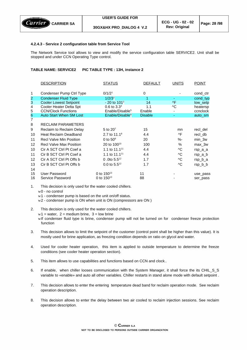
4.2.4.3 - Service 2 configuration table from Service Tool
The Network Service tool allows to view and modify the service configuration table SERVICE2. Unit shall bestopped and under CCN Operating Type control.
TABLE NAME: SERVICE2 PIC TABLE TYPE : 13H, instance 2
DESCRIPTION STATUS DEFAULT UNITS POINT
1 Condenser Pump Ctrl Type 0/1/21 0 - cond_ctr2 Condenser Fluid Type 1/2/32 1 - cond_typ3 Cooler Lowest Setpoint - 20 to 1013 14 ^F low_setp4 Cooler Heater Delta Spt 0.6 to 3.34 1.1 ^C heatersp5 CCN/Clock Functions Enable/Disable5 Enable - ccnclock6 Auto Start When SM Lost Enable/Disable6 Disable - auto_sm78 RECLAIM PARAMETERS9 Reclaim to Reclaim Delay 5 to 207 15 mn recl_del10 Heat Reclaim Deadband 2.7 to 11.18 4.4 ^F recl_db11 Recl Valve Min Position 0 to 509 20 %- min_3w12 Recl Valve Max Position 20 to 10010 100 % max_3w10 Cir A SCT Ctrl Pt Coef a 1.1 to 11.111 4.4 ^C rsp_a_a11 Cir B SCT Ctrl Pt Coef a 1.1 to 11.111 4.4 ^C rsp_a_b12 Cir A SCT Ctrl Pt Offs b 0 .0to 5.512 1.7 ^C rsp_b_a13 Cir B SCT Ctrl Pt Offs b 0.0 to 5.512 1.7 ^C rsp_b_b1415 User Password 0 to 15013 11 - use_pass16 Service Password 0 to 15013 88 - ser_pass
1. This decision is only used for the water cooled chillers.w 0 - no controlw 1 - condenser pump is based on the unit on/off status.w 2 - condenser pump is ON when unit is ON (compressors are ON )
2. This decision is only used for the water cooled chillers.w 1 = water, 2 = medium brine, 3 = low brine w If condenser fluid type is brine, condenser pump will not be turned on for condenser freeze protection
function
3. This decision allows to limit the setpoint of the customer (control point shall be higher than this value). It ismostly used for brine application, as freezing condition depends on ratio on glycol and water.
4. Used for cooler heater operation, this item is applied to outside temperature to determine the freezeconditions (see cooler heater operation section).
5. This item allows to use capabilities and functions based on CCN and clock..
6. If enable, when chiller looses communication with the System Manager, it shall force the its CHIL_S_Svariable to «enable» and auto all other variables. Chiller restarts in stand alone mode with default setpoint .
7. This decision allows to enter the entering temperature dead band for reclaim operation mode. See reclaimoperation description.
8. This decision allows to enter the delay between two air cooled to reclaim injection sessions. See reclaimoperation description.
© CARRIER S.ANOT TO BE DISCLOSED TO PERSONS OUTSIDE CARRIER ORGANIZATION
CARRIER SAUSER'S GUIDE FOR
30GX&HX PRO_DIALOG 4 V.2 ECG - UG - 02 - 02
Rev: OriginalPage: 28 /98

9. This decision allows to set the minimum position in percent of the reclaim condenser water valve. See reclaim operation description.
10. This decision allows to set the maximum position in percent of the reclaim condenser water valve. Seereclaim operation. See reclaim operation description.
11. coefficient A in delta F / percent for circuit. This decision allows to set the coefficient A of the saturatedcondensing temperature control point determination (rsp_a, for circuit A or rsp_b for circuit B) for eachcircuit when reclaim operation is active. See the items description below and reclaim operation description.
12. offset B in delta F. This decision allows to set the offset B of the saturated condensing temperature controlpoint determination (rsp_a, for circuit A or rsp_b for circuit B) for each circuit when reclaim operation isactive.
Thus each circuit will have its control point as follows :rsp_x = (hr_ewt + hr_lwt )/ 2 + rsp_x_a * cap_t_x / 100 + rsp_x_b:cap_t_x = current capacity in percent of the circuitx = circuit A or circuit B
13. User and service passwords used on main interface.
4.2.4.4 - Service 2 configuration table from main interface
The main interface allows to view and modify the service configuration table SERVICE2. Unit shall be stoppedand service password or factory password are required.
reclaim SCT control point determination, offset B, circuit B ^Crsp b b16[2]
reclaim SCT control point determination, offset B, circuit A ^Crsp b a15[2]
reclaim SCT control point determination, coef A , circuit B ^C%rsp a b14[2]
reclaim SCT control point determination, coef A , circuit A ^C%rsp_a_a13[2]
reclaim water valve maximum position%max_3w12[2]
reclaim water valve minimum position%min_3w11[2]
reclaim to reclaim delay minuterecl_del10[2]
reclaim entering temperature deadband^Chr deadb9[2]
Service password.-ser pass8
User password.-use_pass7
Auto restart when loss of communication with SM. Not dislayed if the control is notfitted with the optional CCN/clock board (ccnclock = yes).
-auto_sm6[1]
Clock capabilities select. Not displayed if the control is not fitted with the optionalCCN/clock board (RTC_CHIP_PRESENT = no). Always displayed when ccnclock =yes.
-ccnclock5[1]
Cooler lowest setpoint°Clow setp4[1]
Cooler heater delta setpoint.^Cheatersp5[1]
Condenser fluid type.-cond typ2Condenser control type.-cond_ctr1
When selected this item shall allow to return to main menu.--0
COMMENTSUNITSVARIABLEITEM #
© CARRIER S.ANOT TO BE DISCLOSED TO PERSONS OUTSIDE CARRIER ORGANIZATION
CARRIER SAUSER'S GUIDE FOR
30GX&HX PRO_DIALOG 4 V.2 ECG - UG - 02 - 02
Rev: OriginalPage: 29 /98

4.2.4.5 - Service 3 configuration table from Service Tool
The Network Service tool allows to view and modify the service configuration table MAINCFG. Unit should bestopped and under CCN Operating Type control.
TABLE NAME: MAINTCFG PIC TABLE TYPE : 13H, instance 4
DESCRIPTION STATUS DEFAULT UNITS POINT
1 MAINTENANCE CONFIG23 Servicing Alert Enable/Disable Disable - s_alert45 Refrigerant Charge Ctrl Enable/Disable Disable - charge_c6 Water Loop Control Enable/Disable Disable - wloop_c7 Air Exchanger Control Enable/Disable Disable - aexch_c89 CPump 1 Ctl Delay (days) 0 to 1000 0 - cpump1_c10 CPump 2 Ctl Delay (days) 0 to 1000 0 - cpump2_c11 HPump Ctrl Delay (days) 0 to 1000 0 hpump_c12 Water Filter Ctrl (days) 0 to 1000 0 - wfilte_c13 A1 Oil Filter Ctl (days) 0 to 1000 0 ofila1_c14 A2 Oil Filter Ctl (days) 0 to 1000 0 ofila2_c15 B1 Oil Filter Ctl (days) 0 to 1000 0 ofilb1_c16 B2 Oil Filter Ctl (days) 0 to 1000 0 ofilb2_c
4.2.4.6 - Service 3 configuration table from main interface
The main interface allows to view and modify the service configuration table MAINCFG. Unit should be stoppedand service password or factory password are required.
Oil filer b2 next service in days (displayed only cap b2 > 0)-ofilb2 m12[1]
Oil filer b1 next service in days (displayed only cap_b1> 0)-ofilb1_m11[1]
Oil filer a2 next service in days (displayed only cap_a2 > 0)-ofila2_m10[1]
Oil filer a1 next service in days.-ofila1 m9[1]
Water filter next service in days.-wfilte m8[1]
Condenser water pump next service in days, (displayed only if recl_opt = yes orunit typ = 2 or 3 and cond tr > 0)
-hpump_m7[1]
Cooler water pump #2 next service in days (displayed only if pump_seq > 1)-cpump2_m6[1]
Cooler water pump #1 next service in days (displayed only if pump_seq > 0)-cpump1_m5[1]
Air exchanger control select -aexch m4[1]
Water loop size control select -wloop m3[1]
Refrigerant charge control select -charge m2[1]
Reset maintenance select.-s reset1
When selected this item shall allow to return to the main menu.-0COMMENTSUNITSVARIABLEITEM #
This table is used for service maintenance alert and not available today.
© CARRIER S.ANOT TO BE DISCLOSED TO PERSONS OUTSIDE CARRIER ORGANIZATION
CARRIER SAUSER'S GUIDE FOR
30GX&HX PRO_DIALOG 4 V.2 ECG - UG - 02 - 02
Rev: OriginalPage: 30 /98

4.2.4.7 - Service 4 configuration table from Service Tool
The Network Service tool allows to view and modify the service configuration table UPDTHOUR. Unit should bestopped and under CCN Operating Type control.
TABLE NAME: UPDTHOUR PIC TABLE TYPE : 13H, instance 3
DESCRIPTION STATUS UNITS POINT
1 TABLE TO BE USED FOR RUN 2 TIMES & STARTS UPDATE IN 3 CASE OF CONTROL RETROFIT45 Machine Operating Hours nnnnn hours hr_mach6 Machine Starts nnnnn - st_mach7 Compressor A1 Hours nnnnn hours hr_cp_a18 Compressor A2 Hours nnnnn hours hr_cp_a29 Compressor A1 Starts nnnnn - st_cp_a110 Compressor A2 Starts nnnnn - st_cp_a211 Compressor B1 Hours nnnnn hours hr_cp_b112 Compressor B2 Hours nnnnn hours hr_cp_b213 Compressor B1 Starts nnnnn - st_cp_b114 Compressor B2 Starts nnnnn - st_cp_b215 Cooler Pump #1 Hours nnnnn hours hr_cpum116 Cooler Pump #2 Hours nnnnn hours hr_cpum217 Condenser Pump Hours nnnnn hours hr_hpump
Note: this table shall be used for purposes of transplanting the devices on time or starts number in the event of amodule hardware failure or software upgrade via downloading. It shall be usable only if all items are still nul.Afterwards, its access shall be denied.
4.2.4.8 - Service 4 configuration table from main interface, runtime sub menu
The main interface allows to view and modify the service configuration table UPDTHOUR. Unit shalld be stoppedand service password or factory password are required.
Condenser Pump operating hours. Not displayed if cond_ctr =0 or recl opt =0 and uni typ =1 or 4
hrs/10 or 100hr_hpump15 [1]
Cooler Pump #2 operating hours. Only if pump_seq > 1.hrs/10 or 100hr_cpum214 [1]
Cooler Pump #1 operating hours. Only if pump seq > 0.hrs/10 or 100hr cpum113 [1]
Average of Maximum number of compressors starts/hourduring last 24 hours
-st_cp_av12
Maximum number of compressors starts during last hour-st cp mx11
Compressor B2 starts (only if cap_b2 > 0)-/10 or 100st_cp_b210 [1]
Compressor B1 starts (only if cap_b1 > 0)-/10 or 100st_cp_b19 [1]
Compressor A2 starts (only if cap a2 > 0)-/10 or 100st cp a28 [1]
Compressor A1 starts-/10 or 100st cp a17
Machine starts-/10 or 100st mach6
Compressor B2 operating hours (only if cap b2 > 0)hrs/10 or 100hr cp b25 [1]
Compressor B1 operating hours (only if cap_b1 > 0)hrs/10 or 100hr_cp_b14 [1]
Compressor A2 operating hours (only if cap_a2 > 0)hrs/10 or 100hr_cp_a23 [1]
Compressor A1 operating hourshrs/10 or 100hr cp a12
Machine operating hourshrs/10 or 100hr mach1
When selected this item shall allow to return to the mainmenu.
-0COMMENTSUNITSVARIABLEITEM #
© CARRIER S.ANOT TO BE DISCLOSED TO PERSONS OUTSIDE CARRIER ORGANIZATION
CARRIER SAUSER'S GUIDE FOR
30GX&HX PRO_DIALOG 4 V.2 ECG - UG - 02 - 02
Rev: OriginalPage: 31 /98
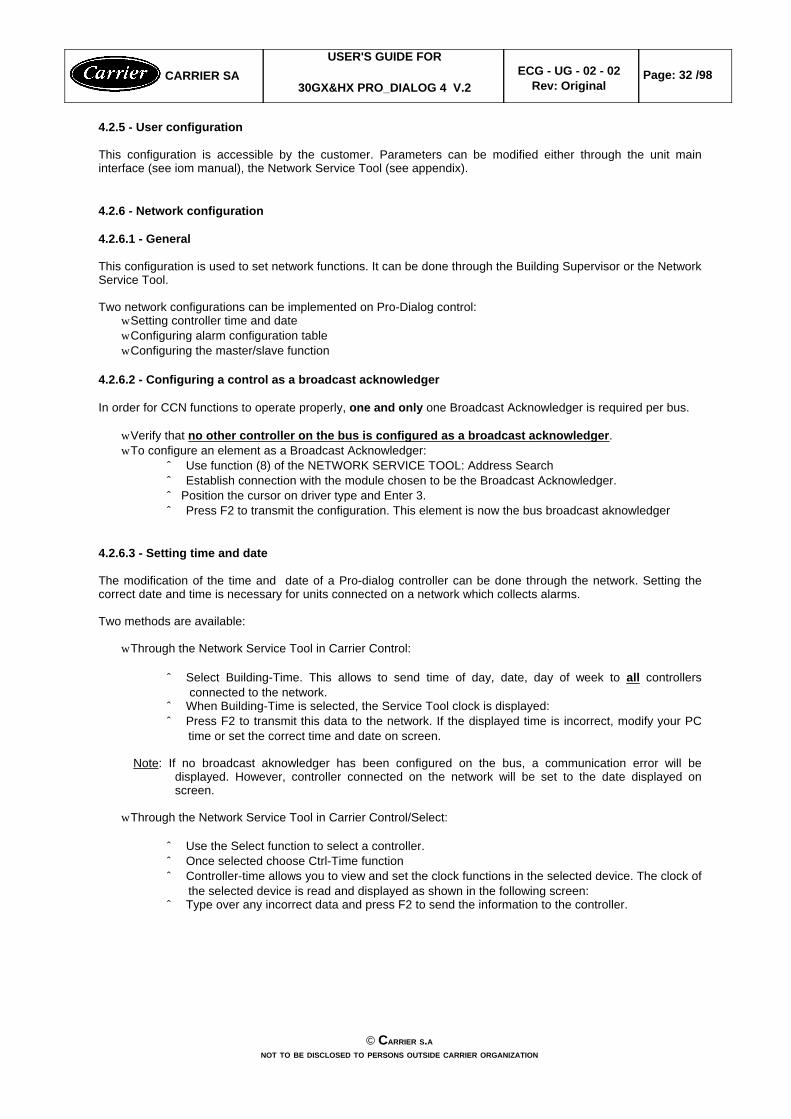
4.2.5 - User configuration
This configuration is accessible by the customer. Parameters can be modified either through the unit maininterface (see iom manual), the Network Service Tool (see appendix).
4.2.6 - Network configuration
4.2.6.1 - General
This configuration is used to set network functions. It can be done through the Building Supervisor or the NetworkService Tool.
Two network configurations can be implemented on Pro-Dialog control:w Setting controller time and datew Configuring alarm configuration tablew Configuring the master/slave function
4.2.6.2 - Configuring a control as a broadcast acknowledger
In order for CCN functions to operate properly, one and only one Broadcast Acknowledger is required per bus.
w Verify that no other controller on the bus is configured as a broadcast acknowledger.w To configure an element as a Broadcast Acknowledger:
ˆ Use function (8) of the NETWORK SERVICE TOOL: Address Searchˆ Establish connection with the module chosen to be the Broadcast Acknowledger.ˆ Position the cursor on driver type and Enter 3. ˆ Press F2 to transmit the configuration. This element is now the bus broadcast aknowledger
4.2.6.3 - Setting time and date
The modification of the time and date of a Pro-dialog controller can be done through the network. Setting thecorrect date and time is necessary for units connected on a network which collects alarms.
Two methods are available:
w Through the Network Service Tool in Carrier Control:
ˆ Select Building-Time. This allows to send time of day, date, day of week to all controllersconnected to the network.
ˆ When Building-Time is selected, the Service Tool clock is displayed:ˆ Press F2 to transmit this data to the network. If the displayed time is incorrect, modify your PC
time or set the correct time and date on screen.
Note: If no broadcast aknowledger has been configured on the bus, a communication error will bedisplayed. However, controller connected on the network will be set to the date displayed onscreen.
w Through the Network Service Tool in Carrier Control/Select:
ˆ Use the Select function to select a controller.ˆ Once selected choose Ctrl-Time functionˆ Controller-time allows you to view and set the clock functions in the selected device. The clock of
the selected device is read and displayed as shown in the following screen:ˆ Type over any incorrect data and press F2 to send the information to the controller.
© CARRIER S.ANOT TO BE DISCLOSED TO PERSONS OUTSIDE CARRIER ORGANIZATION
CARRIER SAUSER'S GUIDE FOR
30GX&HX PRO_DIALOG 4 V.2 ECG - UG - 02 - 02
Rev: OriginalPage: 32 /98

4.2.6.4 - Pro-Dialog alarm configuration table
The Pro-Dialog control has an alarm configuration table associated with it: ALARMDEF. This table can beaccessed through the Modify Controller menu of the Network Service Tool. This table needs to be configuredonly if the unit is network connected to a Building Supervisor, an Autodial Gateway or a Dataport 2, and only ifthese options are configured to receive network alarms.
The parameters which are configured in this table determine the handling of alarms.
TABLE NAME: ALARMDEF PIC TABLE TYPE : 14H, instance 4
DESCRIPTION STATUS DEFAULT POINT
1 Alarm Routing Control 0-11111111 00000000 ALRM_CNT2 Alarm Equipment Priority 0 - 7 4 EQP_TYP3 Comm Failure Retry Time 1 - 240 min 10 RETRY_TM4 Realarm Time 1 - 255 min 30 RE_ALARM5 Alarm System Name 8 chars PD4_GXHX ALRM_NAM
ALARMDEF Decisions description:
ALARM ROUTING CONTROL
This decision determines which CCN system elements will receive and process alarms sent by thePro-Dialog. Input for the decision consists of eight digits, each of which can be set to either 0 or 1. Setting adigit to 1 specifies that alarm will be sent to the system element that correspond to that digit. Setting all digitsto 0 disables alarm processing. Digits in this decision correspond to CCN elements in the following manners:
Note: If the CCN network does not contain a Building Supervisor, Autodial Gateway, or Dataport 2 toserve as an alarm acknowledger, all digits in this decision shall be set to 0 in order to preventunnecessary activity on the CCN communication bus.
Allowable Entries 0 = Disabled1 = Enabled
Default 00000000
ALARM EQUIPMENT PRIORITY
A Building Supervisor uses the value in this decision when sorting alarms by level. Within any group ofalarms that all have the same level, the Building Supervisor sorts alarms according to Alarm EquipmentPriority.
Allowable Entries 0 to 7 (priority numbers)
Default 4
COMM FAILURE RETRY TIME
© CARRIER S.ANOT TO BE DISCLOSED TO PERSONS OUTSIDE CARRIER ORGANIZATION
CARRIER SAUSER'S GUIDE FOR
30GX&HX PRO_DIALOG 4 V.2 ECG - UG - 02 - 02
Rev: OriginalPage: 33 /98
0 0 0 0 0 0 0 00 0 0 0 0 0 0 00 0 0 0 0 0 0 00 0 0 0 0 0 0 0
Local BuildingSupervisor(s)
Autodial Gateway(s)
Dataport 2

This decision specifies the amount of time that will be allowed to elapse between alarm retries. Retries occurwhen an alarm is not acknowledged by a network alarm acknowledger, which may be either a BuildingSupervisor, an Autodial Gateway, or a Dataport 2. If the acknowledgement is not received, the alarm will beretransmitted after the number of minutes specified in this decision.
Allowable Entries 1 to 240 minutes
Default 10 minutes
REALARM TIME
This decision specifies the amount of time that will be allowed to elapse between re-alarms. A re-alarmoccurs when the condition that caused the initial alarm continues to persist for the number of minutesspecified in this decision. Re-alarming will continue to occur at the specified interval until the conditioncausing the alarm is corrected.
Allowable Entries 1 to 254 minutes
Default 30 minutes
ALARM SYSTEM NAME
This decision specifies the system element name that will appear in alarms generated by the Pro-Dialogcontrol.
Allowable Entries Up to 8 alphanumeric characters
Default PRO_30GX
© CARRIER S.ANOT TO BE DISCLOSED TO PERSONS OUTSIDE CARRIER ORGANIZATION
CARRIER SAUSER'S GUIDE FOR
30GX&HX PRO_DIALOG 4 V.2 ECG - UG - 02 - 02
Rev: OriginalPage: 34 /98

4.2.6.5 - Master/Slave configuration table
The MST_SLV table can be accessed through the Modify Controller menu of the Network Service Tool or themain interface. This table needs to be configured if the master/slave function is used. Master/slave functionallows the Pro-Dialog unit to operate as master or a slave in a two chillers plant. See section 4.20.
TABLE NAME: MST_SLV PIC TABLE TYPE : 10H, instance 3
DESCRIPTION STATUS DEFAULT UNITS POINT
1 MASTER/SLAVE CONTROL23 Master/Slave Select: 0/1/21 0 - ms_sel4 0 = Disable5 1 = Master6 2 = Slave7 Master Control Type: 1/2/3 1 - ms_ctrl8 1 = Local Control9 2 = Remote Control10 3 = CCN Control11 Slave Address 1 to 236 1 - slv_addr12 Lag Start Timer 2 to 302 10 min lstr_tim13 Lead/Lag Balance Yes/No3 No - ll_bal14 Lead/Lag Balance Delta 40 to 4004 168 hours ll_bal_d15 Lag Unit Pump Control 0/1 0 - lag_pump16 0 = Stop if Unit Stops17 1 = Run if Unit Stops18 Lead Pulldown Time 0 to 605 0 minutes lead_pul
Decisions description:
1. This decision allows the unit to operate as master or a slave in a two chillers master/slave. The masterchiller monitors all external commands as start/stop, demand limiting, setpoint select or reset via CCN bus.Control of the slave chiller is done through commands (start/stop, demand limit, setpoint, heat cool)emitted by the master chiller. The slave will not be allowed to operate as a slave if its CHIL_S_S,CTRL_PNT or DEM_LIM, HC_SEL variables has a force priority higher than a control force.
2. This timer is started when all conditions to start the lag chiller are satisfied. Lag chiller shall not be starteduntil this timer is elapsed. To be set in the master unit table only.
3. This decision allows to activate two chillers lead/lag balance function. It is used for master/slave chillerrunning time equalization. When this function is active, once per day or each time the master chiller isswitched from the off to the on state the control determines the lead chiller based on both chillers run hoursdelta. When the run hours delta is greater than the configured lead/lag balance delta then a changeoverwill occur and the unit with the smallest operating hours value will become the lead. This function cannotoperate if the master chiller demand limit is less than 100%. In that case, the master chiller will always bethe lead. To be set in the master unit table only.
4. This function allows to set the lead/lag balance delta used for master/slave chiller running timeequalization. Lead/lag changeover occurs when the lead/lag operating time delta overlaps the configuredbalance value and provided that master unit is not under demand limit control.
5. This decision allows to set the lead chiller pull down duration before the lag chiller starts.
© CARRIER S.ANOT TO BE DISCLOSED TO PERSONS OUTSIDE CARRIER ORGANIZATION
CARRIER SAUSER'S GUIDE FOR
30GX&HX PRO_DIALOG 4 V.2 ECG - UG - 02 - 02
Rev: OriginalPage: 35 /98

4.3 - Cooler Interlock contact
A contact to check the status of a safety loop is provided (cooler flow switch and customer interlock are wiredinternally in series). Its function is to prevent the unit from starting if the contact is open while the delay at startup hasexpired. The contact must also stay closed as long as the unit is not stopped through Local, Remote or CCN control.
If the cooler pump is controlled by the pro-dialog and if the cooler contact is closed after 2 minutes the cooler pumpis turned OFF provided that the contact is failed CLOSED, the alarm 75 shall be active and the unit can't no morestart until manual reset.
4.4 - Cooler heater control
This function is applied only for air cooled units and is related to the cooler pump function when the unit state is OFFor when unit operates as a lag chiller in master/slave operation and in standby mode. This is provided on outdoorunit as a safeguard against the cooler freezing. The cooler heater is associated with refrigerant isolation solenoids,one output per circuit whose goal is to prevent the refrigerant from migrating into the condenser when chiller isstopped.
The following logic shall be used:
w If the outdoor air temperature is below the cooler heater trip point and if either the saturated suction temperatureof circuit A or saturated suction temperature of circuit B are lower than the cooler heater trip point plus 3.3 ^C,the cooler heater shall be activated.
w Normally the isolation valves shall prevent refrigerant in the cooler from migrating into the condenser. For thiscase, cooler heater can ensure cooler protection efficiently without the need of using cooler pump.
w If it is not the case (SST remain low), the pump shall be turned on every 7 minutes to check freezing conditionsand additional heat to the cooler : cooler fluid temp (< 3° - [SSTa + SSTb]/2). Pump shall be turned of if coolerfluid temp > (8°C - [SSTa + SSTb]/2).
w If both saturated suction temperatures of circuit A and circuit B are greater than the cooler heater trip point plus5.5 ^C, the cooler heater shall be turned off. The pump shall be allowed to stop.
heater trip point = freeze + heat_spt (heat_sp from SERVICE2 table)freeze = 1.1 for water, coldest setpoint - 4.4^C for brine
4.5 - Oil heater control
Each circuit has its own oil separator fitted with an oil heater. Both circuit oil heater are controlled independently .Since there is no oil temperature sensor, the oil heater will be controlled based on the saturated condensingtemperature as follows :
wOil heater ON when outside temperature is below 17°C.wOil heater OFF when outside temperature is above 25°CwOil heater OFF when circuit is in operation or oil level is low (oil_sw is OPEN).
4.6 - Motor Cooling Control without plate exchanger economizer
The screw compressor motors used in the Global Chiller control are refrigerant cooled. The control strategy for motorcooling relies on vapor at light loads, and supplementary liquid refrigerant at high loads. Each compressor will haveits own cooling solenoid. An additional motor cooling solenoid is required when operating in high condensingtemperature. It is automatically controlled by pro-dialog even if it is not mounted in the units. The motor coolingsolenoids shall be cycled to allow liquid to cool the motor. The main motor cooling solenoid control is based on themotor temperature and its setpoint (83°C) using a quasi-fuzzy logic. The additional motor cooling solenoid control isjust based on the discharge gas temperature.
CARRIER SAUSER'S GUIDE FOR
30GX&HX PRO_DIALOG 4 V.2ECG-UG-02-002
Rev: OriginalPage: 36/98
© CARRIER S.ANOT TO BE DISCLOSED TO PERSONS OUTSIDE CARRIER ORGANIZATION
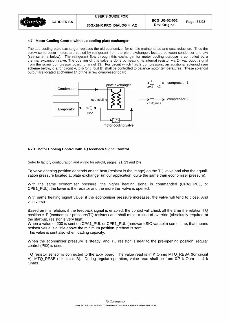
4.7 - Motor Cooling Control with sub cooling plate exchanger
The sub cooling plate exchanger replaces the old economizer for simple maintenance and cost reduction. Thus thescrew compressor motors are cooled by refrigerant from the plate exchanger, located between condenser and exv(see scheme below). The refrigerant flow through this exchanger for motor cooling purpose is controlled by athermal expansion valve. The opening of this valve is done by heating its internal resistor via 24 vac ouput signalfrom the screw compressor board, channel 13. For circuit which has 2 compressors, an additional solenoid (seescheme below, x=a for circuit A, x=b for circuit B) shall be controlled to balance motor temperatures. These solenoidoutput are located at channel 14 of the screw compressor board.
Evaporator
Condenser
EXV
motor cooling valve
sub-cooling
plate exchanger compressor 1
compressor 2
cpx1_mc2
cpx2_mc2
4.7.1 Motor Cooling Control with TQ feedback Signal Control
(refer to factory configuration and wiring for retrofit, pages, 21, 23 and 24)
Tq valve opening position depends on the heat (resistor is the image) on the TQ valve and also the equali-sation pressure located at plate exchanger (in our application, quite the same than economiser pressure).
With the same economiser pressure, the higher heating signal is commanded (CPA1_PUL, orCPB1_PUL), the lower is the resistor and the more the valve is opened.
With same heating signal value, if the economiser pressure increases, the valve will tend to close. Andvice versa
Based on this relation, if the feedback signal is enabled, the control will check all the time the relation TQposition = F (economiser pressure/TQ resistor) and shall make a kind of override (absolutely required atthe start-up, resistor is very high)When a value of 200 is sent on CPA1_PUL or CPB1_PUL (hardware SIO variable) some time, that meansresistor value is a little above the minimum position, preheat is sent.This value is sent also when loading capacity.
When the economiser pressure is steady, and TQ resistor is near to the pre-opening position, regularcontrol (PID) is used.
TQ resistor sensor is connected to the EXV board. The value read is in K Ohms MTQ_RESA (for circuitA), MTQ_RESB (for circuit B). During regular operation, value read shall be from 0.7 k Ohm to 4 kOhms.
CARRIER SAUSER'S GUIDE FOR
30GX&HX PRO_DIALOG 4 V.2ECG-UG-02-002
Rev: OriginalPage: 37/98
© CARRIER S.ANOT TO BE DISCLOSED TO PERSONS OUTSIDE CARRIER ORGANIZATION

4.8 - CAPACITY CONTROL
This function adjusts the number of active compressors and loaders to keep the leaving water temperature at thesetpoint. The precision with which this is achieved depends upon the capacity of the water loop, the water flowrate, the load and the number of capacity control steps available. The control continuously takes account of thetemperature error with respect to the control point, the rate of change of the leaving fluid temperature and the deltaof temperatures between the entering and leaving fluid in order to determine the optimum time to add or subtractsteps of capacity.
Note: a too important number of starts of a particular compressor will automatically cause a limitation of thecompressors starts. This will affect the precision of the water loop temperature control.
4.8.1 - Logic description
4.8.1.1 - Basic logic
To operate the capacity control task uses the following inputs:w EWT Entering water temperaturew LWT Leaving water temperaturew CTRL_PNT Control pointw Cooling z_multiplier Z Multiplier (range: 1.0 to 6.0)w Heating z_multiplier Z Multiplier (range: 1.0 to 6.0)
The control calculates the SMZ: load/unload factor. It is compared to the z_multiplier to determine when to add orremove stage:
w If (sum/z) > +z_multiplier -> stage = +1 (add a compressor)w If (sum/z) > +0.6 and if a loader is available (loader is OFF) -> stage = +1 (add a loader)w If (sum/z) < - z_multiplier -> stage = -1 (remove one compressor)w If sum/z) < -0.6 and loader is avaialble (loader is ON) -> stage = -1 (turn off one loader)
Note: z_multiplier doesn't apply to loaders.
4.8.1.2 - Z Multiplier calculation
The z_multiplier factor allows to indirectly increase the compressor on/off time delay. In consequence, it can beadjusted (increased) to avoid compressors short cycling. This function requires the following Service configuration:
vAuto Z Multiplier sepoint (zm_spt). Default to 6.vCooling and heating Z Multiplier max value (hc_zm). default to 6.0.
This function adapts the z_multiplier to the unit compressor cycles number (the cycle number shall be based onthe compressor which has been the most started during an hour). The significant period for compressors cyclingshall be of one hour.
If the cycle counter exceeds the setpoint (zm_spt), then the z_multiplier value shall be increased based on thecycle number (PID loop). The function shall not take care of the loaders cycling.
The calculated value of the z_multiplier shall not exceed the configured hc_zm. If the unit returns to normal operating condition with a cycles counter going down then the calculated z_multipliershall progressively return to its normal value (zm = 1.0). The rate at which the calculated z_multiplier returns tonormal shall be lower than the rate at which it is increased.
The setpoint value shall allow to adapt the auto z multiplier calculation to the installation. The setpoint rangesfrom 4 to 6.
During normal operation, each modification of the unit capacity is followed by a dead time when no capacitymodification is possible. The duration of this dead time is 90 seconds.
4.8.1.3 - Overrides
CARRIER SAUSER'S GUIDE FOR
30GX&HX PRO_DIALOG 4 V.2ECG-UG-02-002
Rev: OriginalPage: 38/98
© CARRIER S.ANOT TO BE DISCLOSED TO PERSONS OUTSIDE CARRIER ORGANIZATION

sum/z ratio will be overridden if any one of the following conditions is satisfied.
1 Cooler freeze protection2,3 Very Low saturated suction temperature4 Low source temperature protection5,6 Low discharge superheat temperature7, 8 Low temperature Cooling/High temperature heating9 Demand limit10 Cooler Lock11 Slow change override12 Ramp loading13 Minimum ON/OFF delay14 High temperature cooling and low temperature heating15 System Manager control16, 17 High pressure18,19 High current20, 21 Low saturated suction temperature22,23,24,25 High condensing temperature28 Compressor startup with loader 1 on due to low condensing temperature26, 27 Low Oil Level when circuit is OFF29,30 Stopping circuit due to low oil level (allowed thrice within 2 hours) before going to alarm31,32 High motor temperature on economizer units (T° > 93°C) 33,34 Stopping compressor due high motor temperature (T° > 110°C, allowed thrice within 2 hours)
before going to alarm35 Chiller current limit
Note : When overrides 2,3 , 5, 6, 16, 17, 18, 19, 20, 21 are active, the variable close control (cls_ctrl) shall beenabled whatever the configuration to allow unloading the last loader in the circuit.
Chiller Current Override (override #35)
This function allows customer to limit the total current (it does not include current of fans, valves, heaters, oil pumps...) of all the compressors during operation. The chiller current limit can be modified through USER configuration(USER table or User configuration by main interface). This function is similar to demand limit function.
wIf the chiller current is greater than the chiller current limit , then a stage of capacity will be removed.wIf chiller current plus the added current of selected compressor is greater than the chiller current limit, the
increase of capacity will not be allowed. If the compressors is OFF, its added current is 80% of its MTA. If theselected compressor is on but deos not reach 100% capacity, an added stage on the same compressor will add40% of its current.
CARRIER SAUSER'S GUIDE FOR
30GX&HX PRO_DIALOG 4 V.2ECG-UG-02-002
Rev: OriginalPage: 39/98
© CARRIER S.ANOT TO BE DISCLOSED TO PERSONS OUTSIDE CARRIER ORGANIZATION
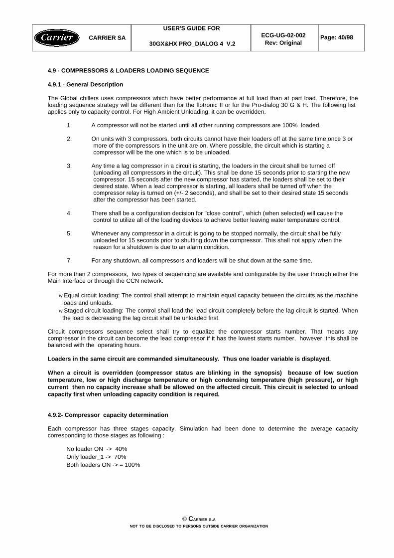
4.9 - COMPRESSORS & LOADERS LOADING SEQUENCE
4.9.1 - General Description
The Global chillers uses compressors which have better performance at full load than at part load. Therefore, theloading sequence strategy will be different than for the flotronic II or for the Pro-dialog 30 G & H. The following list applies only to capacity control. For High Ambient Unloading, it can be overridden.
1. A compressor will not be started until all other running compressors are 100% loaded.
2. On units with 3 compressors, both circuits cannot have their loaders off at the same time once 3 ormore of the compressors in the unit are on. Where possible, the circuit which is starting acompressor will be the one which is to be unloaded.
3. Any time a lag compressor in a circuit is starting, the loaders in the circuit shall be turned off(unloading all compressors in the circuit). This shall be done 15 seconds prior to starting the newcompressor. 15 seconds after the new compressor has started, the loaders shall be set to theirdesired state. When a lead compressor is starting, all loaders shall be turned off when thecompressor relay is turned on (+/- 2 seconds), and shall be set to their desired state 15 secondsafter the compressor has been started.
4. There shall be a configuration decision for "close control", which (when selected) will cause thecontrol to utilize all of the loading devices to achieve better leaving water temperature control.
5. Whenever any compressor in a circuit is going to be stopped normally, the circuit shall be fullyunloaded for 15 seconds prior to shutting down the compressor. This shall not apply when thereason for a shutdown is due to an alarm condition.
7. For any shutdown, all compressors and loaders will be shut down at the same time.
For more than 2 compressors, two types of sequencing are available and configurable by the user through either theMain Interface or through the CCN network:
w Equal circuit loading: The control shall attempt to maintain equal capacity between the circuits as the machineloads and unloads.
w Staged circuit loading: The control shall load the lead circuit completely before the lag circuit is started. Whenthe load is decreasing the lag circuit shall be unloaded first.
Circuit compressors sequence select shall try to equalize the compressor starts number. That means anycompressor in the circuit can become the lead compressor if it has the lowest starts number, however, this shall bebalanced with the operating hours.
Loaders in the same circuit are commanded simultaneously. Thus one loader variable is displayed.
When a circuit is overridden (compressor status are blinking in the synopsis) because of low suctiontemperature, low or high discharge temperature or high condensing temperature (high pressure), or highcurrent then no capacity increase shall be allowed on the affected circuit. This circuit is selected to unloadcapacity first when unloading capacity condition is required.
4.9.2- Compressor capacity determination
Each compressor has three stages capacity. Simulation had been done to determine the average capacitycorresponding to those stages as following :
No loader ON -> 40%Only loader_1 -> 70%Both loaders ON -> = 100%
CARRIER SAUSER'S GUIDE FOR
30GX&HX PRO_DIALOG 4 V.2ECG-UG-02-002
Rev: OriginalPage: 40/98
© CARRIER S.ANOT TO BE DISCLOSED TO PERSONS OUTSIDE CARRIER ORGANIZATION

4.9.3- Staged Loading Increasing Capacity Logic
ONON2ONON2
OFFON2ONON2
ONON1ONON2
OFFON1ONON2
OFFOFF0ONON2
OFFOFF0OFFON2
OFFOFF0ONON1
OFFOFF0OFFON1
OFFOFF0OFFOFF1
OFFOFF0OFFOFF0
LOADER2
LOADER1
NUMBER OFCOMPRESSORS
LOADER2
LOADER1
NUMBER OFCOMPRESSORS
LAG CIRCUIT LEAD CIRCUIT
4.9.4- Equal Loading Increasing Capacity Logic with close_control = NO
ONON2ONON2
OFFON2ONON2
ONON1ONON2
ONON1OFFON2
ONON1ONON1
OFFON1ONON1
OFFON1OFFON1
OFFOFF0ONON1
OFFOFF0OFFON1
OFFOFF0OFFOFF1
OFFOFF0OFFOFF0
LOADER2
LOADER1
NUMBER OFCOMPRESSORS
LOADER2
LOADER1
NUMBER OFCOMPRESSORS
LAG CIRCUIT LEAD CIRCUIT
CARRIER SAUSER'S GUIDE FOR
30GX&HX PRO_DIALOG 4 V.2ECG-UG-02-002
Rev: OriginalPage: 41/98
© CARRIER S.ANOT TO BE DISCLOSED TO PERSONS OUTSIDE CARRIER ORGANIZATION
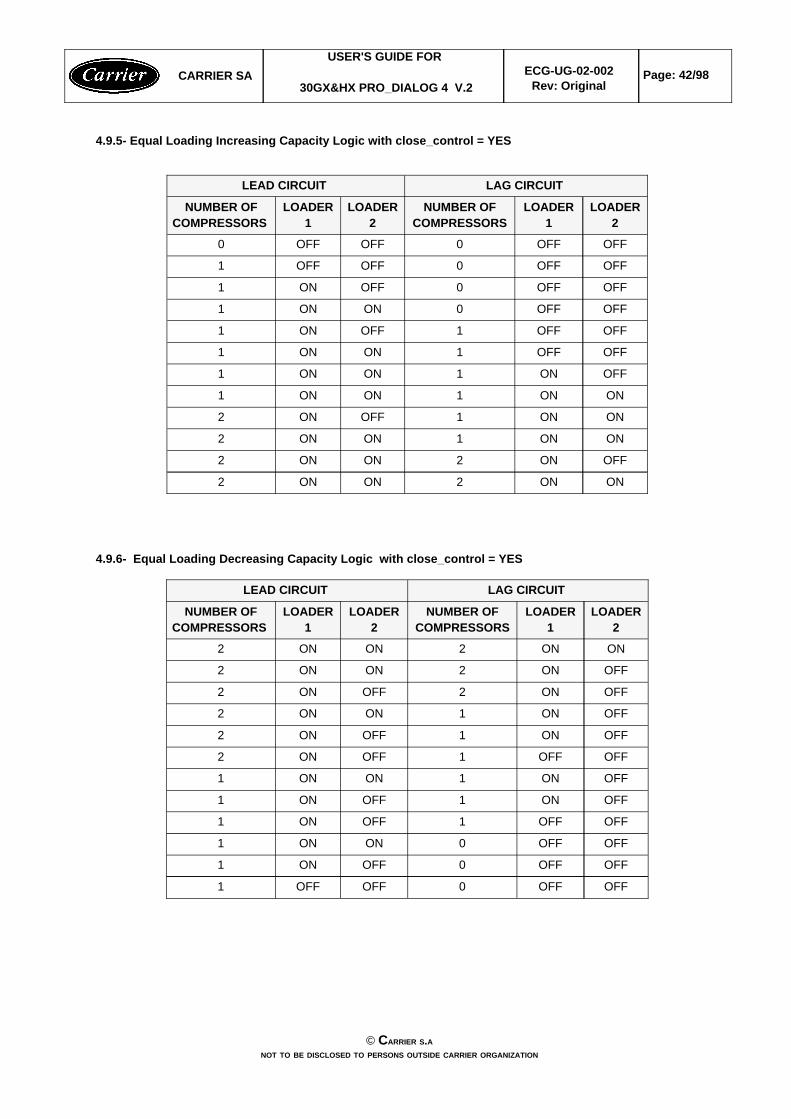
4.9.5- Equal Loading Increasing Capacity Logic with close_control = YES
ONON2ONON2
OFFON2ONON2
ONON1ONON2
ONON1OFFON2
ONON1ONON1
OFFON1ONON1
OFFOFF1ONON1
OFFOFF1OFFON1
OFFOFF0ONON1
OFFOFF0OFFON1
OFFOFF0OFFOFF1
OFFOFF0OFFOFF0
LOADER2
LOADER1
NUMBER OFCOMPRESSORS
LOADER2
LOADER1
NUMBER OFCOMPRESSORS
LAG CIRCUIT LEAD CIRCUIT
4.9.6- Equal Loading Decreasing Capacity Logic with close_control = YES
OFFOFF0OFFOFF1
OFFOFF0OFFON1
OFFOFF0ONON1
OFFOFF1OFFON1
OFFON1OFFON1
OFFON1ONON1
OFFOFF1OFFON2
OFFON1OFFON2
OFFON1ONON2
OFFON2OFFON2
OFFON2ONON2
ONON2ONON2
LOADER2
LOADER1
NUMBER OFCOMPRESSORS
LOADER2
LOADER1
NUMBER OFCOMPRESSORS
LAG CIRCUIT LEAD CIRCUIT
CARRIER SAUSER'S GUIDE FOR
30GX&HX PRO_DIALOG 4 V.2ECG-UG-02-002
Rev: OriginalPage: 42/98
© CARRIER S.ANOT TO BE DISCLOSED TO PERSONS OUTSIDE CARRIER ORGANIZATION

4.9.7 - Equal Loading Decreasing Capacity Logic with close_control = NO
OFFOFF0OFFOFF0
OFFOFF0OFFOFF1
OFFOFF0OFFON1
OFFOFF0ONON1
OFFON1OFFON1
OFFON1ONON1
ONON1ONON1
OFFON1ONON2
ONON1ONON2
OFFON2ONON2
ONON2ONON2
LOADER2
LOADER1
NUMBER OFCOMPRESSORS
LOADER2
LOADER1
NUMBER OFCOMPRESSORS
LAG CIRCUIT LEAD CIRCUIT
4.9.8 - Staged Loading Decreasing Capacity Logic with close_control = NO
OFFOFF0OFFOFF0
OFFOFF0OFFOFF1
OFFOFF0OFFON1
OFFOFF0ONON1
OFFOFF0OFFON2
OFFOFF0ONON2
OFFON1ONON2
ONON1ONON2
OFFON2ONON2
ONON2ONON2
LOADER2
LOADER1
NUMBER OFCOMPRESSORS
LOADER2
LOADER1
NUMBER OFCOMPRESSORS
LAG CIRCUIT LEAD CIRCUIT
CARRIER SAUSER'S GUIDE FOR
30GX&HX PRO_DIALOG 4 V.2ECG-UG-02-002
Rev: OriginalPage: 43/98
© CARRIER S.ANOT TO BE DISCLOSED TO PERSONS OUTSIDE CARRIER ORGANIZATION

4.9.9 - Staged Loading Decreasing Capacity Logic with close_control = YES
OFFOFF0OFFOFF0
OFFOFF0OFFOFF1
OFFOFF0OFFON1
OFFOFF0ONON1
OFFOFF0OFFON2
OFFOFF1OFFON2
OFFOFF1ONON2
OFFON1ONON2
ONON1ONON2
OFFON2ONON2
ONON2ONON2
LOADER2
LOADER1
NUMBER OFCOMPRESSORS
LOADER2
LOADER1
NUMBER OFCOMPRESSORS
LAG CIRCUIT LEAD CIRCUIT
CARRIER SAUSER'S GUIDE FOR
30GX&HX PRO_DIALOG 4 V.2ECG-UG-02-002
Rev: OriginalPage: 44/98
© CARRIER S.ANOT TO BE DISCLOSED TO PERSONS OUTSIDE CARRIER ORGANIZATION

4.10 - EXV CONTROL
4.10.1 - General
The EXV is controlled to maintain minimum pinch for insuring the cooler exchange performance through the deltatemperature between the cooler fluid and the saturated suction temperature. EXV opening movement will normallydecrease the cooler pinch and thus increase the cooler exchange performance. But it shall not open too muchprovided a drop in discharge superheat , low oil pressure and refrigerant flow.
The EXV control shall deal with two goals : Smaller Cooler Pinch and Discharge Superheat Protection.
Additional protection against excessive EXV opening is applied to ensure the condenser heat transfer (sub cooling).It may happen when operating in high condensing temperature and indirectly high discharge superheat, exv wouldtend to open continuously to get the lower pinch due to the setpoint and unfortunately in certain conditions, this valuehas reached the limit, though it is higher than the setpoint. Therefore, EXV position limit shall be set when there isno more variation in cooler pinch for a variation of EXV position of 4 percent.
EXV position shall also be limited to avoid hunting problem due to low discharge superheat protection. It may occurwhen operating in a low condensing temperature, the discharge superheat protection can switch from enable todisable in few scans and so on.
This control uses a kind of auto adaptive method whose goal is to find out the optimal position of EXV for insuring anoptimal pinch with a correct discharge superheat and sub cooling.
4.10.2 - Overrides
over_exv Override Description with and priority precedence.
1 Low ambient startup 2 Low Saturated Suction Temperature3 Very Low Saturated Suction Temperature4 Very Low Discharge Superheat5 Mop control (Closing EXV)6 Cooler pinch regular control7 Reclaim injection override8 High Saturated Suction Temperature (no movement)9 Low Saturated Suction with High Saturated Condensing Temperature10,11 Capacity increase12,13, 14 Capacity decrease15 Reclaim pumpdown session16,17 Discharge Superheat lower than control point18, 20 Safeguard Discharge Superheat 19 Exv position limitation active21,26 Safeguard optimal cooler pinch due high Discharge Superheat or lower exv
position22 Closing EXV due to good pinch and high motor temperature for economizer unit 23 Exv position limitation active, and go back to previous position24, 25 EXV limitation is reinitialized
CARRIER SAUSER'S GUIDE FOR
30GX&HX PRO_DIALOG 4 V.2ECG-UG-02-002
Rev: OriginalPage: 45/98
© CARRIER S.ANOT TO BE DISCLOSED TO PERSONS OUTSIDE CARRIER ORGANIZATION

4.11 - Air Cooled Condensing Pressure Control
Head pressure differential value and head pressure differential timer can be adjusted in the Service menu.Decreasing these values will increase fan cycling. This differential value and timer can be reduced since the unit isfitted with an important number of fan stages, as to increase the condensing control accuracy. But in certain cases,notably on units with few fan stages, at too small value can causes superheat hunting problems.Varifan PID gains can be modified in the Service menu (not recommended). See section 4.2.3.
SCT control point without varifan
To avoid fan cycles and also to ensure a minimum expected SCT for oil pressure, SCT control shall beadjusted based on OAT, the same for SCT differential as
55°C (13°F1)
OAT20°c0°c68°F32°F
+ 1 fan
- 1 fan
SCT control point
35°C (95°F)
40°C (104°F)35°C (95°F)
SCT Diff
4.12.1 - Air Cooled Condensing Pressure Control - Fan staging with Aux board
Each DO shall support only one fan. The first DO is not used if varifan is present to standardize the wayof making connection and to avoid wiring mistake.
4.12.2 - Air Cooled Condensing Pressure Control - Fan staging
The combination described here below is for 4 fans configured maximum, each DO commands 1 fan
4fan_1 + fan_2 + fan_3 + fan_4onononon43fan_1 + fan_2+ fan_3 offononon32fan_1 + fan_2offoffonon21fan_1offoffoffon100offoffoffoff0
totalfans
fans controlledDO_4DO_3DO_2DO_1stage
CARRIER SAUSER'S GUIDE FOR
30GX&HX PRO_DIALOG 4 V.2ECG-UG-02-002
Rev: OriginalPage: 46/98
© CARRIER S.ANOT TO BE DISCLOSED TO PERSONS OUTSIDE CARRIER ORGANIZATION

The following combinations are used for a circuit with more than 4 fans configured
5fan_1 + fan_2 + fan_3 + fan_4 + fan_5onononon54fan_1 + fan_2 + fan_3 + fan_4offononon43fan_1 + - + fan_3 + fan_4offonoffon32fan_1 + fan_2offoffonon21fan_1offoffoffon100offoffoffoff0
total fans
fans controlledDO_4DO_3DO_2DO_1stage
6fan_1+ fan_2 + fan_3 + fan_4 + fan_5 + fan_6onononon65fan_1+ - + fan_3 + fan_4+ fan_5 + fan_6 ononoffon54fan_1+ fan_2 + fan_3 + fan_4offononon43fan_1+ - + fan_3 + fan_4offonoffon32fan_1+ fan_2offoffonon21fan_1offoffoffon10-offoffoffoff0
total fans
fans controlledDO_4DO_3DO_2DO_1stage
7fan_1 + fan_2 + fan_3 + fan_4 + fan_5 + fan_6 + fan_7onononon76fan_1 + - + fan_3 + fan_4 + fan_5 + fan_6 + fan_7ononoffon65fan_1 + fan_2 + - + - + fan_5 + fan_6 + fan_7 onoffonon54fan_1 + fan_2 + fan_3 + fan_4offononon43fan_1 + - + fan_3 + fan_4offonoffon32fan_1 + fan_2offoffonon21fan_1offoffoffon10-offoffoffoff0
total fans
fans controlledDO_4DO_3DO_2DO_1stage
8fan_1 + fan_2 + fan_3 + fan_4 + fan_5 + fan_6 + fan_7 + fan_8onononon87fan_1 + - + fan_3 + fan_4 + fan_5 + fan_6 + fan_7 + fan_8ononoffon76fan_1 + fan_2 + - + - + fan_5 + fan_6 + fan_7 + fan_8onoffonon65fan_1 + - + - + - + fan_5 + fan_6 + fan_7 + fan_8onoffoffon54fan_1 + fan_2 + fan_3 + fan_4offononon43fan_1 + - + fan_3 + fan_4offonoffon32fan_1 + fan_2offoffonon21fan_1offoffoffon10-offoffoffoff0
total fans
fans controlledDO_4DO_3DO_2DO_1stage
4.13 - Water Cooled Condensing Pressure Control
The control of a common water valve for both circuits is required. The water valve control will be based on thehighest saturated condensing temperature of both circuit or based on the operating circuit if the other is OFF.
Water valve PID gains can be modified in the Service menu (when unit is OFF). See section 4.2.3. They areaccessible though the table SERVICE1 and can be modified during operation.
CARRIER SAUSER'S GUIDE FOR
30GX&HX PRO_DIALOG 4 V.2ECG-UG-02-002
Rev: OriginalPage: 47/98
© CARRIER S.ANOT TO BE DISCLOSED TO PERSONS OUTSIDE CARRIER ORGANIZATION
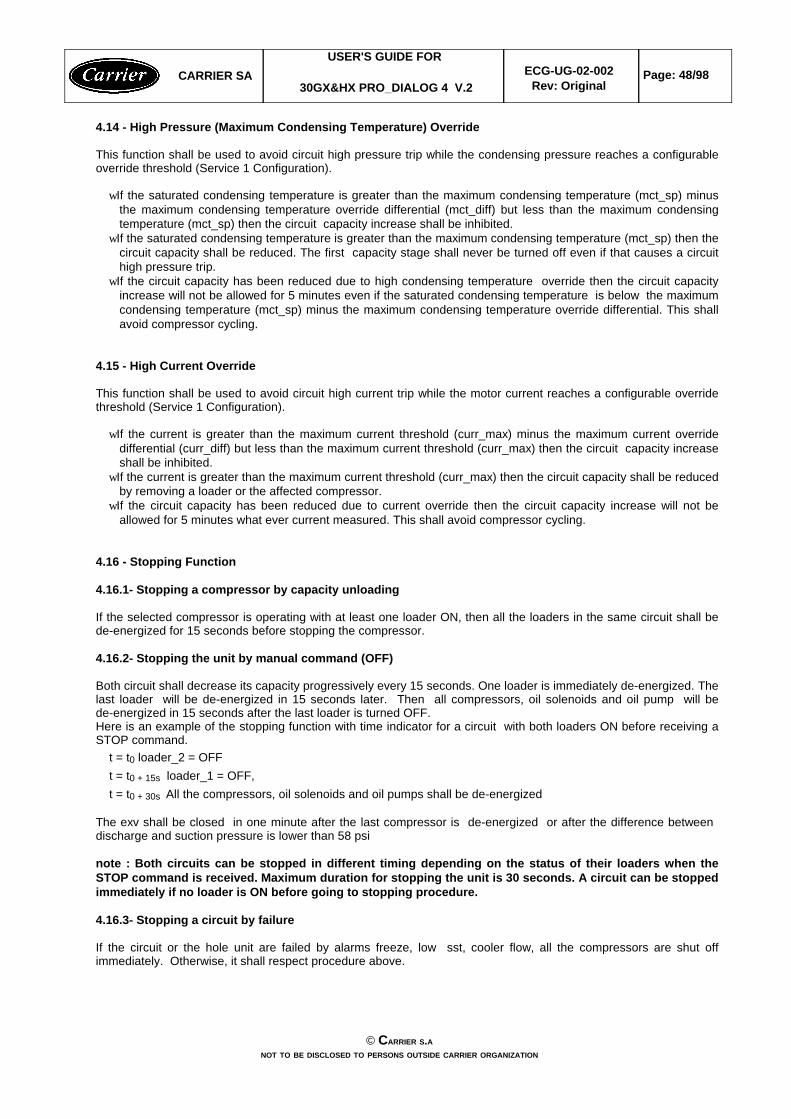
4.14 - High Pressure (Maximum Condensing Temperature) Override
This function shall be used to avoid circuit high pressure trip while the condensing pressure reaches a configurableoverride threshold (Service 1 Configuration).
wIf the saturated condensing temperature is greater than the maximum condensing temperature (mct_sp) minusthe maximum condensing temperature override differential (mct_diff) but less than the maximum condensingtemperature (mct_sp) then the circuit capacity increase shall be inhibited.
wIf the saturated condensing temperature is greater than the maximum condensing temperature (mct_sp) then thecircuit capacity shall be reduced. The first capacity stage shall never be turned off even if that causes a circuithigh pressure trip.
wIf the circuit capacity has been reduced due to high condensing temperature override then the circuit capacityincrease will not be allowed for 5 minutes even if the saturated condensing temperature is below the maximumcondensing temperature (mct_sp) minus the maximum condensing temperature override differential. This shallavoid compressor cycling.
4.15 - High Current Override
This function shall be used to avoid circuit high current trip while the motor current reaches a configurable overridethreshold (Service 1 Configuration).
wIf the current is greater than the maximum current threshold (curr_max) minus the maximum current overridedifferential (curr_diff) but less than the maximum current threshold (curr_max) then the circuit capacity increaseshall be inhibited.
wIf the current is greater than the maximum current threshold (curr_max) then the circuit capacity shall be reducedby removing a loader or the affected compressor.
wIf the circuit capacity has been reduced due to current override then the circuit capacity increase will not beallowed for 5 minutes what ever current measured. This shall avoid compressor cycling.
4.16 - Stopping Function
4.16.1- Stopping a compressor by capacity unloading
If the selected compressor is operating with at least one loader ON, then all the loaders in the same circuit shall bede-energized for 15 seconds before stopping the compressor.
4.16.2- Stopping the unit by manual command (OFF)
Both circuit shall decrease its capacity progressively every 15 seconds. One loader is immediately de-energized. Thelast loader will be de-energized in 15 seconds later. Then all compressors, oil solenoids and oil pump will bede-energized in 15 seconds after the last loader is turned OFF.Here is an example of the stopping function with time indicator for a circuit with both loaders ON before receiving aSTOP command. t = t0 loader_2 = OFF t = t0 + 15s loader_1 = OFF, t = t0 + 30s All the compressors, oil solenoids and oil pumps shall be de-energized
The exv shall be closed in one minute after the last compressor is de-energized or after the difference between discharge and suction pressure is lower than 58 psi
note : Both circuits can be stopped in different timing depending on the status of their loaders when theSTOP command is received. Maximum duration for stopping the unit is 30 seconds. A circuit can be stoppedimmediately if no loader is ON before going to stopping procedure.
4.16.3- Stopping a circuit by failure
If the circuit or the hole unit are failed by alarms freeze, low sst, cooler flow, all the compressors are shut offimmediately. Otherwise, it shall respect procedure above.
CARRIER SAUSER'S GUIDE FOR
30GX&HX PRO_DIALOG 4 V.2ECG-UG-02-002
Rev: OriginalPage: 48/98
© CARRIER S.ANOT TO BE DISCLOSED TO PERSONS OUTSIDE CARRIER ORGANIZATION

4.17- Oil pressure control
4.17.1- Oil pressure Setpoint determination
The following algorithm applies to all unit types:
104 86 70 Oil setpoint 1(kpa)> 350240 < AND <350< 240Suction pressure (kpa)
Oil Setpoint2 is calculated as follows:
0.63645* (DP - SP) + 35 2* (DP - SP) - 1516 0.235* (DP - SP) + 4Oil setpoint 2(kpa)> 1137861 < AND < 1137< 861DP - SP (kpa)
* DP = Discharge Pressure* SP = Suction pressure
4.17.2- Oil pump control
The oil pump is generally used to provide pre-lubrification of the compressor. Moreover, it is controlled to insure acorrect oil pressure during capacity transition or during operation with low condensing temperature that cause a dropof oil pressure to avoid tripping in alarm.
Thus the oil pump is turned ON when the Differential Oil Pressure is lower than Oil Setpoint 1 plus 13 kpa. and remained ON until Differential Oil Pressure is greater than Oil Setpoint 1 plus 35 kpa AND difference betweendischarge and economizer pressure is greater than Oil Setpoint 1 plus 150 kpa to avoid oil pump cycles.
4.17.3- Low Oil pressure alarm determination
ALARM 68 for Compressor A1, ALARM 69 for Compressor A2, ALARM 70 for Compressor B1, ALARM 71 forCompressor B2.
Criteria For Trip Tested only when the compressor is ON.
DOP: Differential Oil Pressure for the appropriate compressor. DOP = Oil pressure - Economizer pressure.
Economizer pressure is the common (econ_sel = YES) Economizer Pressure transducer reading for thecircuit involved or the appropriate economizer pressure transducer (econ_sel = NO) associated to thecompressor.
A. Compressor has started with Normal Ambient (oat > 10 °C) or or condenser temperature (temp > 18°C)
1. If the compressor has been running for less than 5 seconds then ignore the alarm.
2. If the compressor has been running for more than 5 seconds but less than 30 seconds andDOP < (Oil Setpoint1/30)*(Comp. Running Time [in seconds])for 3 continuous readings, then the alarm shall be tripped.
3. If the compressor has been running for 30 seconds or more, then if:a). DOP < Oil pressure setpoint1 for 15 continuous seconds,
ORb). (Poil - Psuction) < Oil pressure setpoint2 for 15 continuous seconds,then the alarm shall be tripped
B. Compressor has started with Low Ambient (oat < 10 °C) or low condenser temperature (temp < 18°C)
1. If the compressor has been running for less than 90 seconds then ignore the alarm.
CARRIER SAUSER'S GUIDE FOR
30GX&HX PRO_DIALOG 4 V.2ECG-UG-02-002
Rev: OriginalPage: 49/98
© CARRIER S.ANOT TO BE DISCLOSED TO PERSONS OUTSIDE CARRIER ORGANIZATION

2. If the compressor has been running for more than 90 seconds but less than 180 seconds andDOP < (Oil Setpoint1/90)*(Comp. Running Time [in seconds] - 90)for 3 continuous readings, then the alarm shall be tripped.
3. If the compressor has been running for 180 seconds or more, then if:a). DOP < Oil pressure setpoint1 for 15 continuous seconds,
ORb). (Poil - Psuction) < Oil pressure setpoint2 for 15 continuous seconds,then the alarm shall be tripped.
Action To Be Taken
1. If the alarm is tripped then the affected compressor shall be stopped. The other compressors shallcontinue to run.
4.17.4- Differential Oil Pressure Setpoint 1 alarm condition summary.
CARRIER SAUSER'S GUIDE FOR
30GX&HX PRO_DIALOG 4 V.2ECG-UG-02-002
Rev: OriginalPage: 50/98
© CARRIER S.ANOT TO BE DISCLOSED TO PERSONS OUTSIDE CARRIER ORGANIZATION
0
Dif
fere
ntia
l O
il p
ress
ure
requ
ired
180s
oil pressure trip
Oil pressure trip with low ambient or
90s30s5s
oil setpoint1oil setpoint1oil setpoint1oil setpoint1
3 continued3 continued3 continued3 continued
reading valuesreading valuesreading valuesreading values
3 continued3 continued3 continued3 continuedreading valuesreading valuesreading valuesreading values
15 s delay15 s delay
time from start
low condensing temperature
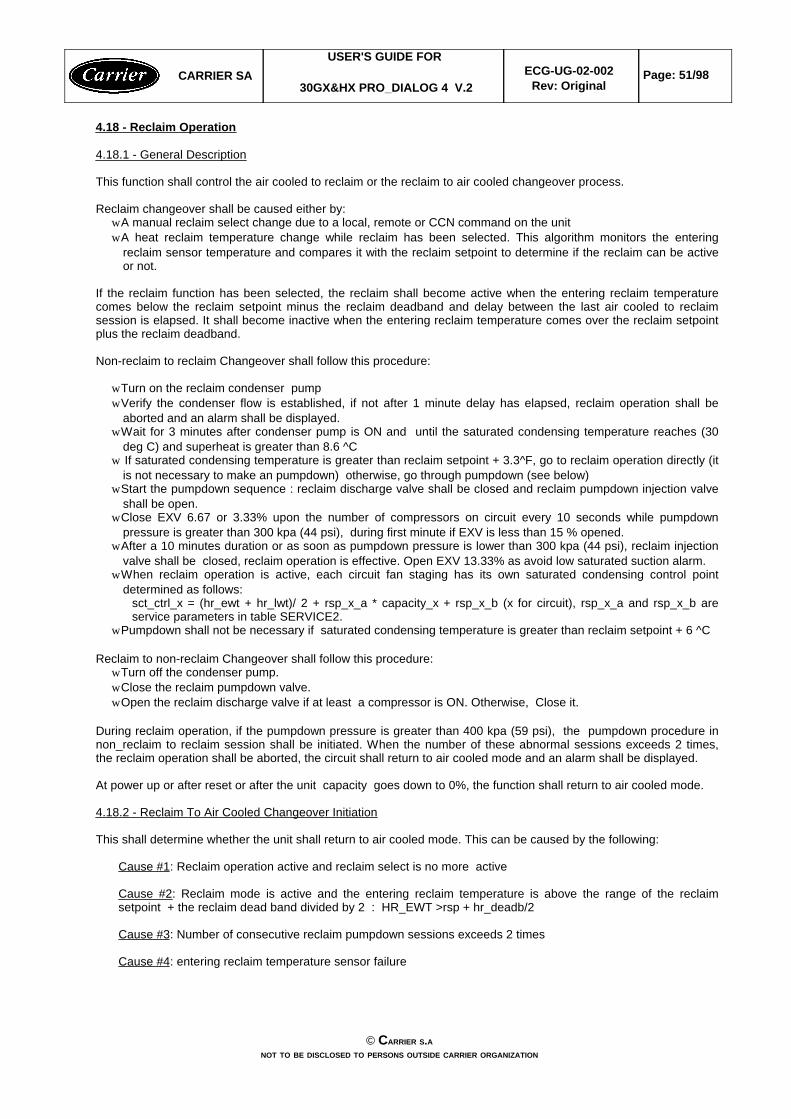
4.18 - Reclaim Operation
4.18.1 - General Description
This function shall control the air cooled to reclaim or the reclaim to air cooled changeover process.
Reclaim changeover shall be caused either by:w A manual reclaim select change due to a local, remote or CCN command on the unitw A heat reclaim temperature change while reclaim has been selected. This algorithm monitors the entering
reclaim sensor temperature and compares it with the reclaim setpoint to determine if the reclaim can be activeor not.
If the reclaim function has been selected, the reclaim shall become active when the entering reclaim temperaturecomes below the reclaim setpoint minus the reclaim deadband and delay between the last air cooled to reclaimsession is elapsed. It shall become inactive when the entering reclaim temperature comes over the reclaim setpointplus the reclaim deadband.
Non-reclaim to reclaim Changeover shall follow this procedure:
w Turn on the reclaim condenser pumpw Verify the condenser flow is established, if not after 1 minute delay has elapsed, reclaim operation shall be
aborted and an alarm shall be displayed.w Wait for 3 minutes after condenser pump is ON and until the saturated condensing temperature reaches (30
deg C) and superheat is greater than 8.6 ^Cw If saturated condensing temperature is greater than reclaim setpoint + 3.3^F, go to reclaim operation directly (it
is not necessary to make an pumpdown) otherwise, go through pumpdown (see below)w Start the pumpdown sequence : reclaim discharge valve shall be closed and reclaim pumpdown injection valve
shall be open.w Close EXV 6.67 or 3.33% upon the number of compressors on circuit every 10 seconds while pumpdown
pressure is greater than 300 kpa (44 psi), during first minute if EXV is less than 15 % opened. w After a 10 minutes duration or as soon as pumpdown pressure is lower than 300 kpa (44 psi), reclaim injection
valve shall be closed, reclaim operation is effective. Open EXV 13.33% as avoid low saturated suction alarm.w When reclaim operation is active, each circuit fan staging has its own saturated condensing control point
determined as follows:sct_ctrl_x = (hr_ewt + hr_lwt)/ 2 + rsp_x_a * capacity_x + rsp_x_b (x for circuit), rsp_x_a and rsp_x_b areservice parameters in table SERVICE2.
w Pumpdown shall not be necessary if saturated condensing temperature is greater than reclaim setpoint + 6 ^C
Reclaim to non-reclaim Changeover shall follow this procedure:w Turn off the condenser pump. w Close the reclaim pumpdown valve. w Open the reclaim discharge valve if at least a compressor is ON. Otherwise, Close it.
During reclaim operation, if the pumpdown pressure is greater than 400 kpa (59 psi), the pumpdown procedure innon_reclaim to reclaim session shall be initiated. When the number of these abnormal sessions exceeds 2 times,the reclaim operation shall be aborted, the circuit shall return to air cooled mode and an alarm shall be displayed.
At power up or after reset or after the unit capacity goes down to 0%, the function shall return to air cooled mode.
4.18.2 - Reclaim To Air Cooled Changeover Initiation
This shall determine whether the unit shall return to air cooled mode. This can be caused by the following:
Cause #1: Reclaim operation active and reclaim select is no more active
Cause #2: Reclaim mode is active and the entering reclaim temperature is above the range of the reclaimsetpoint + the reclaim dead band divided by 2 : HR_EWT >rsp + hr_deadb/2
Cause #3: Number of consecutive reclaim pumpdown sessions exceeds 2 times
Cause #4: entering reclaim temperature sensor failure
CARRIER SAUSER'S GUIDE FOR
30GX&HX PRO_DIALOG 4 V.2ECG-UG-02-002
Rev: OriginalPage: 51/98
© CARRIER S.ANOT TO BE DISCLOSED TO PERSONS OUTSIDE CARRIER ORGANIZATION

4.18.3 - Air Cooled To Reclaim Changeover Initiation
A non-reclaim to reclaim injection session has been required and at least one compressor is on and the unit is notfailed and the entering reclaim temperature is not failed and this one is below the reclaim setpoint - half of configuredreclaim deadband and delay between the last reclaim injection has elapsed.
4.18.4 - Reclaim Operation status hr_status Description
Information on reclaim operation is available on table RECLAIM (hrstatus) or on INFORMATION menu (hr_status).hr_status parameter shall contain reclaim operation indicator of both circuit in two digits, one digit per circuit (left digitfor circuit A, the other for circuit B) with the following description :
Reclaim failed due to flow switch 5
Reclaim pumpdown failed 4
Reclaim operation active3
Reclaim pumpdown mode2
Reclaim mode request 1
Air cooled operation0
Status descriptionreclaim operationindicator
*note : in case of reclaim operation failure (alarm # 83 for circuit A, alarm # 84 for circuit B), hr_status will not beinitialized until the manual reset on main interface is done.
4.18.5 - Reclaim Operation Using Air Cooled Exchanger
To avoid high pressure problem, the remained condenser (hr_val_x) can be turned ON if SCT is above reclaimsetpoint + 8.3 deg C and all fans are ON provided that fans staging is not enough to avoid the risk of exceeding highpressure override threshold. When turning ON, the remained condenser (hr_val_a) is kept to ON for at least 3minutes to let fans staging to be stabilized. This condenser can be turned OFF if it has been ON for more than 3minutes and if saturated condensing temperature is below the reclaim setpoint (rsp) to ensure the reclaim operationperformance.
4.18.6 - Reclaim Condenser Water Valve Control
if unit is not in reclaim operation, then the reclaim condenser water valve remains in minimum position.
In reclaim operation : wIf reclaim entering temperature is below 20 deg C, then reclaim condenser valve is at minimum position.wIf reclaim entering temperature is above 40 deg C, then reclaim condenser valve is at maximum position.wIf entering temperature is within the range 20 degC and 40 deg C, then reclaim condenser water valve positionwill be an interpolation between minimum and maximum position.
4.18.7 - Reclaim Condenser Heater Control
Reclaim condenser heater is ON when entering or leaving fluid are lower than 3.0 deg C( 37.4 degF). It is turnedOFF when both temperatures are above 4.4 deg C (40.0 deg F).
CARRIER SAUSER'S GUIDE FOR
30GX&HX PRO_DIALOG 4 V.2ECG-UG-02-002
Rev: OriginalPage: 52/98
© CARRIER S.ANOT TO BE DISCLOSED TO PERSONS OUTSIDE CARRIER ORGANIZATION

4.19 - Two Units Master/Slave Control
4.19.1 - General
This function allows to perform master/slave plant control between two chillers linked by the CCN network. Masterand slave chiller need to operate on the same bus. Master/slave operations shall operate in cooling or heating mode.
To operate properly, the master and the slave chillers must have an additional CHWS sensor located on thecommon chilled leaving piping when the water control is done on the outlet side. This CHWS sensor shall beconnected on each chiller basic board. When the water system control is done on the inlet side no additional CHWSsensor is required.
Parallel chiller control with dedicated pumps is recommended. Chiller must start and stop its own water pumplocated on its own piping. If pumps are not dedicated for each chiller pimping, chiller isolation valves are required:each chiller must open and close its own isolation valve through the control (valve shall be connected to the pumpoutputs).
Water system control with no individual chiller pump control is feasible. It is not recommended when the system loadis low or if the control point is close from the freeze water tripping point (because of system instability that can becaused by the freeze protection override). System flow is constant even if the master or the slave chiller is stopped.In that case, the system pump shall be controlled by the master chiller.
Series chillers with dedicated primary pumping and constant flow shall be feasible but not recommended. Pumpstart/stop must be controlled externally. Each series chiller must control its own isolation and bypass valves: stoppedchiller must be isolated from water flow (chiller pump command shall be used for valves control. Each chiller mustopen and close its own chilled isolation valve).
The master chiller shall monitor all external commands as start/stop, demand limiting or setpoint select. It needs tobe started in Master operating type. The slave chiller must operate in CCN mode. If the master chiller is turned offwhile the master/slave function is active then, the slave chiller shall be stopped.
The master/slave linkage shall not be allowed to operate if any one of the slave chiller CTRL_PNT, DEM_LIM,LAG_LIM, CTRL_PNT HC_SEL or LCW_STPT variables has a force priority higher than a control force. In that case,the master slave operations shall not be allowed or shall be disabled.
The control of the slave chiller shall be done through commands emitted by the master chiller. The slave chiller hasno action in the master/slave operations: it shall only verify that CCN communication with its master is correct.
The master function shall provide the ability to select a lead chiller among the master and the slave. Selection shallbe based on the delta between the master and the slave run hours and shall try to optimize the runtime hours. If thisfunction is unused then, the lead chiller shall always the master. Lead/lag changeover between the master and theslave due to hour balance shall occur during chiller operations odd days at 12:00 a.m. or at startup.
The lead chiller shall always be started first and the lag chiller shall be maintained at zero percent capacity throughmaster forcing the lag demand limit value (LAG_LIM) to 0%. The lag water pump shall be maintained off. When thelead chiller cannot be loaded anymore (because it is loaded at its full available capacity or at the master demandlimit value) then the lag start timer is started. When the lag start timer is elapsed, if the error on the master controlledsetpoint is greater than 3^F and if the pulldown time is elapsed then, the lag chiller water pump shall be turned on (ifrequired by configuration) and the lag chiller shall be allowed to start through master forcing the lag chiller demandlimit value (LAG_LIM) to its own demand limit value. To ensure that the lag chiller will be unloaded first in case ofwater load decrease then, the lead chiller setpoint error shall be reset of upwards 4^F provided that the lag capacityis not zero.
CARRIER SAUSER'S GUIDE FOR
30GX&HX PRO_DIALOG 4 V.2ECG-UG-02-002
Rev: OriginalPage: 53/98
© CARRIER S.ANOT TO BE DISCLOSED TO PERSONS OUTSIDE CARRIER ORGANIZATION
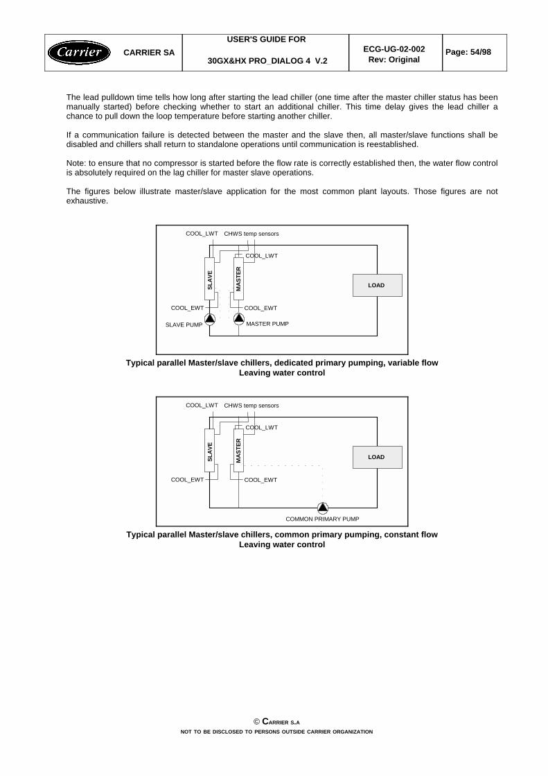
The lead pulldown time tells how long after starting the lead chiller (one time after the master chiller status has beenmanually started) before checking whether to start an additional chiller. This time delay gives the lead chiller achance to pull down the loop temperature before starting another chiller.
If a communication failure is detected between the master and the slave then, all master/slave functions shall bedisabled and chillers shall return to standalone operations until communication is reestablished.
Note: to ensure that no compressor is started before the flow rate is correctly established then, the water flow controlis absolutely required on the lag chiller for master slave operations.
The figures below illustrate master/slave application for the most common plant layouts. Those figures are notexhaustive.
MAS
TER
CHWS temp sensors
COOL_EWTCOOL_EWT
SLAV
E
LOAD
SLAVE PUMP MASTER PUMP
COOL_LWT
COOL_LWT
Typical parallel Master/slave chillers, dedicated primary pumping, variable flowLeaving water control
MAS
TER
CHWS temp sensors
COOL_EWTCOOL_EWT
SLAV
E
LOAD
COMMON PRIMARY PUMP
COOL_LWT
COOL_LWT
Typical parallel Master/slave chillers, common primary pumping, constant flowLeaving water control
CARRIER SAUSER'S GUIDE FOR
30GX&HX PRO_DIALOG 4 V.2ECG-UG-02-002
Rev: OriginalPage: 54/98
© CARRIER S.ANOT TO BE DISCLOSED TO PERSONS OUTSIDE CARRIER ORGANIZATION
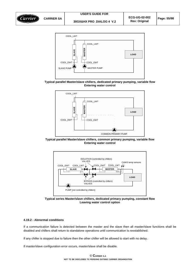
MAS
TER
COOL_EWTCOOL_EWT
SLAV
E
LOAD
SLAVE PUMP MASTER PUMP
COOL_LWT
COOL_LWT
Typical parallel Master/slave chillers, dedicated primary pumping, variable flowEntering water control
MAS
TER
COOL_EWTCOOL_EWT
SLAV
E
LOAD
COMMON PRIMARY PUMP
COOL_LWT
COOL_LWT
Typical parallel Master/slave chillers, common primary pumping, variable flowEntering water control
COOL_EWT
SLAVE
LOAD
CHWS temp sensorsCOOL_EWT COOL_LWTCOOL_LWT
MASTER
PUMP (not controlled by chillers)
ISOLATION (controlled by chillers)VALVES
BYPASS (controlled by chillers)VALVES
Typical series Master/slave chillers, dedicated primary pumping, constant flowLeaving water control option
4.19.2 - Abnormal conditions
If a communication failure is detected between the master and the slave then all master/slave functions shall bedisabled and chillers shall return to standalone operations until communication is reestablished.
If any chiller is stopped due to failure then the other chiller will be allowed to start with no delay.
If master/slave configuration error occurs, master/slave shall be disable.
CARRIER SAUSER'S GUIDE FOR
30GX&HX PRO_DIALOG 4 V.2ECG-UG-02-002
Rev: OriginalPage: 55/98
© CARRIER S.ANOT TO BE DISCLOSED TO PERSONS OUTSIDE CARRIER ORGANIZATION

Master/Slave Error
The following error shall be updated in the M_MSTSLV Maintenance table (priority order):
master and slave heatcool status are not the same.x13No communication with slave.xx12The master chiller operating type is not Master: master_oper_typ ≠ masterx11The slave chiller is down due to fault (chilstat = 5)xx10The slave chiller is in local or remote control (chilstat = 3)xx9
There is a conflict between the master and the slave pump option: the master is notconfigured for lag pump control while the slave is configured for lag pump control.
x8
There is a conflict between the master and the slave pump option: the master is configuredfor lag pump control while the slave is not configured for lag pump control.
x7
There is a conflict between the master and the slave lwt option: the master is configured forlwt control while the slave is configured for ewt control.
x6
There is a conflict between the master and the slave lwt option: the master is configured forewt control while the slave is configured for lwt control.
x5Slave pump_seq incorrect configurationx4There is no slave configured at the slave addressx3Master and slave units have the same network address.x2
The master or slave water pump is not configured while the control of the lag unit pump isrequired (lag_pump = 1)
xx1Normalxx0
DescriptionSlaveMasterErrorcode
Master/Slave alarm code
Note
Master/slave sequence can be controlled through the Network Service Tool or PCDCT tools (see appendix, M_MSTSLV Maintenance Table)
CARRIER SAUSER'S GUIDE FOR
30GX&HX PRO_DIALOG 4 V.2ECG-UG-02-002
Rev: OriginalPage: 56/98
© CARRIER S.ANOT TO BE DISCLOSED TO PERSONS OUTSIDE CARRIER ORGANIZATION

5 - CCN ALARM MESSAGES
The Building Supervisor displays current alarms messages and their return to normal provided that the CCN tableALARMDEF has been correctly configured.
The Network Service Tool Diagnostic Menu allows to display 5 current alarms messages (even if the ALARDEF tableis not configured).
The following gives the messages that shall be displayed by the Building Supervisor or from main interface.
Alarm 1 Cooler Entering ThermistorAlarm 2 Cooler Leaving ThermistorAlarm 3 Condenser Entering ThermistorAlarm 4 Condenser Leaving ThermistorAlarm 5 Reclaim Condenser Entering ThermistorAlarm 6 Reclaim Condenser Leaving ThermistorAlarm 7 OAT ThermistorAlarm 8 MASTER/Slave Common Fluid ThermistorAlarm 9 Compressor A1 Discharge Gas Temperature ThermistorAlarm 10 Compressor A2 Discharge Gas Temperature ThermistorAlarm 11 Compressor B1 Discharge Gas Temperature ThermistorAlarm 12 Compressor B2 Discharge Gas Temperature Thermistor
Alarm 13 0-10V Reset/Limit Input
Alarm 14 Circuit A Discharge TransducerAlarm 15 Circuit B Discharge TransducerAlarm 16 Circuit A Suction TransducerAlarm 17 Circuit B Suction TransducerAlarm 18 Compressor A1 Oil TransducerAlarm 19 Compressor A2 Oil TransducerAlarm 20 Compressor B1 Oil TransducerAlarm 21 Compressor B2 Oil TransducerAlarm 22 Compressor A1 Economizer TransducerAlarm 23 Compressor A2 Economizer TransducerAlarm 24 Compressor B1 Economizer TransducerAlarm 25 Compressor B2 Economizer TransducerAlarm 26 Circuit A Remote Discharge Pressure TransducerAlarm 26 Circuit A Reclaim Pumpdown Pressure TransducerAlarm 27 Circuit B Reclaim Pumpdown Pressure Transducer
Alarm 28 Circuit A Motor Cooling TQ feedback Sensor FailureAlarm 29 Circuit B Motor Cooling TQ feedback Sensor Failure
Alarm 30 Loss of communication with Screw Compressor Board 1Alarm 31 Loss of communication with Screw Compressor Board 2Alarm 32 Loss of communication with Screw Compressor Board 3Alarm 33 Loss of communication with Screw Compressor Board 4Alarm 34 Loss of communication with EXV Board 1Alarm 35 Loss of communication with Fans Board 1Alarm 36 Loss of communication with Fans Board 2Alarm 37 Loss of communication with 4xAI_2xAO or Aux Type 1 Board Alarm 38 Loss of communication with Reclaim or Cooler Heater Board Alarm 39 Loss of communication with CCN / Clock Board
Alarm 40 Electrical Box Thermostat or reverse phase detection FailureAlarm 41 Unit is in CCN emergency stopAlarm 42 Initial factory configuration requiredAlarm 43 Illegal configuration
Alarm 44 Circuit A High PressureAlarm 45 Circuit B High PressureAlarm 46 Compressor A1 Oil Solenoid Failure
CARRIER SAUSER'S GUIDE FOR
30GX&HX PRO_DIALOG 4 V.2ECG-UG-02-002
Rev: OriginalPage: 57/98
© CARRIER S.ANOT TO BE DISCLOSED TO PERSONS OUTSIDE CARRIER ORGANIZATION

Alarm 47 Compressor A2 Oil Solenoid FailureAlarm 48 Compressor B1 Oil Solenoid FailureAlarm 49 Compressor B2 Oil Solenoid FailureAlarm 50 Compressor A1 Prestart Low Oil PressureAlarm 51 Compressor A2 Prestart Low Oil PressureAlarm 52 Compressor B1 Prestart Low Oil PressureAlarm 53 Compressor B2 Prestart Low Oil PressureAlarm 54 Circuit A Low Oil LevelAlarm 55 Circuit B Low Oil LevelAlarm 56 Circuit A Low Suction TemperatureAlarm 57 Circuit B Low Suction TemperatureAlarm 58 Circuit A High Suction TemperatureAlarm 59 Circuit B High Suction TemperatureAlarm 60 Circuit A Low Discharge Superheat Alarm 61 Circuit B Low Discharge Superheat Alarm 62 Compressor A1 Maximum Delta Pressure Check Oil LineAlarm 63 Compressor A2 Maximum Delta Pressure Check Oil LineAlarm 64 Compressor B1 Maximum Delta Pressure Check Oil LineAlarm 65 Compressor B2 Maximum Delta Pressure Check Oil LineAlarm 66 Loss of communication with System Manager Alarm 67 Master/Slave communication FailureAlarm 68 Compressor A1 Low Oil PressureAlarm 69 Compressor A2 Low Oil PressureAlarm 70 Compressor B1 Low Oil PressureAlarm 71 Compressor B2 Low Oil PressureAlarm 72 Cooler Freeze ProtectionAlarm 73 Circuit A Condenser FreezeAlarm 74 Circuit B Condenser FreezeAlarm 75 Cooler Interlock FailureAlarm 76 Condenser Lock FailureAlarm 77 Compressor A1 High CurrentAlarm 78 Compressor A2 High CurrentAlarm 79 Compressor B1 High CurrentAlarm 80 Compressor B2 High CurrentAlarm 81 Cooler Pump 1 DefaultAlarm 82 Cooler Pump 2 DefaultAlarm 83 Circuit A Reclaim Pumpdown Failure Alarm 84 Circuit B Reclaim Pumpdown FailureAlarm 85 Reclaim Operation Failed by Condenser Flow SwitchAlarm 86 Master chiller configuration errorAlarm 87 Service maintenance alert
Alarms compressorAlarm 101 Compressor A1 Motor Temperature Too HighAlarm 102 Compressor A1 Motor Temperaure Out of RangeAlarm 103 Compressor A1 High Pressure SwitchAlarm 104 Compressor A1 Over Current Alarm 105 Compressor A1 Lock RotorAlarm 106 Compressor A1 Ground FaultAlarm 107 Compressor A1 Phase Loss L1Alarm 108 Compressor A1 Phase Loss L2Alarm 109 Compressor A1 Phase Loss L3Alarm 110 Compressor A1 Unbalance > 14 %Alarm 111 Compressor A1 Unbalance > 18 %Alarm 112 Compressor A1 No Motor CurrentAlarm 113 Compressor A1 Star Delta Starter Failure Alarm 114 Compressor A1 Contactor FailureAlarm 115 Compressor A1 Unable To StopAlarm 116 Compressor A1 Phase ReversalAlarm 117 Compressor A1 MTA Configuration Header Fault
CARRIER SAUSER'S GUIDE FOR
30GX&HX PRO_DIALOG 4 V.2ECG-UG-02-002
Rev: OriginalPage: 58/98
© CARRIER S.ANOT TO BE DISCLOSED TO PERSONS OUTSIDE CARRIER ORGANIZATION

Alarm 201 Compressor A2 Motor Temperature Too HighAlarm 202 Compressor A2 Motor Temperature Out of RangeAlarm 203 Compressor A2 High Pressure SwitchAlarm 204 Compressor A2 Over Current Alarm 205 Compressor A2 Lock RotorAlarm 206 Compressor A2 Ground FaultAlarm 207 Compressor A2 Phase Loss L1Alarm 208 Compressor A2 Phase Loss L2Alarm 209 Compressor A2 Phase Loss L3Alarm 210 Compressor A2 Unbalance > 14 %Alarm 211 Compressor A2 Unbalance > 18 %Alarm 212 Compressor A2 No Motor CurrentAlarm 213 Compressor A2 Star Delta Starter Failure Alarm 214 Compressor A2 Contactor FailureAlarm 215 Compressor A2 Unable To StopAlarm 216 Compressor A2 Phase ReversalAlarm 217 Compressor A2 MTA Configuration Header Fault
Alarm 301 Compressor B1 Motor Temperature Too HighAlarm 302 Compressor B1 Motor Temperature Out of RangeAlarm 303 Compressor B1 High Pressure SwitchAlarm 304 Compressor B1 Over Current Alarm 305 Compressor B1 Lock RotorAlarm 306 Compressor B1 Ground FaultAlarm 307 Compressor B1 Phase Loss L1Alarm 308 Compressor B1 Phase Loss L2Alarm 309 Compressor B1 Phase Loss L3Alarm 310 Compressor B1 Unbalance > 14 %Alarm 311 Compressor B1 Unbalance > 18 %Alarm 312 Compressor B1 No Motor CurrentAlarm 313 Compressor B1 Star Delta Starter Failure Alarm 314 Compressor B1 Contactor FailureAlarm 315 Compressor B1 Unable To StopAlarm 316 Compressor B1 Phase ReversalAlarm 317 Compressor B1 MTA Configuration Header Fault
Alarm 401 Compressor B2 Motor Temperature Too HighAlarm 402 Compressor B2 Motor Temperature Out of RangeAlarm 403 Compressor B2 High Pressure SwitchAlarm 404 Compressor B2 Over Current Alarm 405 Compressor B2 Lock RotorAlarm 406 Compressor B2 Ground FaultAlarm 407 Compressor B2 Phase Loss L1Alarm 408 Compressor B2 Phase Loss L2Alarm 409 Compressor B2 Phase Loss L3Alarm 410 Compressor B2 Unbalance > 14 %Alarm 411 Compressor B2 Unbalance > 18 %Alarm 412 Compressor B2 No Motor CurrentAlarm 413 Compressor B2 Star Delta Starter Failure Alarm 414 Compressor B2 Contactor FailureAlarm 415 Compressor B2 Unable To StopAlarm 416 Compressor B2 Phase ReversalAlarm 417 Compressor B2 MTA Configuration Header Fault
CARRIER SAUSER'S GUIDE FOR
30GX&HX PRO_DIALOG 4 V.2ECG-UG-02-002
Rev: OriginalPage: 59/98
© CARRIER S.ANOT TO BE DISCLOSED TO PERSONS OUTSIDE CARRIER ORGANIZATION

6 - CCN COMPATIBILITY
30GX&HX Pro-Dialog 4 Control is compatible with:wThe Building SupervisorwThe Network Service Tool
30GX&HX Pro-Dialog 4 Control is compatible with the following POCs:wAlarm POC IIwAutodial Gateway IIwData Transfer/Collection HistorywDataport 1wDataport 2wSAMwNDSwCCN/JBUS GatewaywFlotronic System ManagerwChiller SYstem Manager III
7 - PRO_DIALOG 4 DOWNLOADER ADDENDUM INFORMATION
The pro_dialog 4 control software shall be downloaded using the downloader version 3.0 or later. Here is theexample of the downloader list (download.lis) which contains only pro_dialog 4 controls :
CESR208410-22 PD4 Global chiller GX & HXC SR 2.2 (1)CESR208400-22 PD4 Recip chiller 30 GK & 30HZ V2 SR 2.2 (1)CESRNRCP53-10 NRCP PD4 SLAVE ADDRESS 53 version 1.0 (2)CESRSCPM10-60 PD4 SCPM board download SR 1.06 (2)
1. Software can be downloaded through CCN bus or through SIO bus2. Software shall only be downloaded through SIO bus. Before downloading the software, use the reset command to erase the old software. Once F2 key is pressed, turn off and on quickly the power supply of the board, the message «Hard restart command successful !». Then go to the downloader , Select download, software and then press F2 to download the software as usual.
The «CESRNRCP53-10» shal be used for Aquasnap basic board download when cooler heater and reclaim optionare selected.
CARRIER SAUSER'S GUIDE FOR
30GX&HX PRO_DIALOG 4 V.2ECG-UG-02-002
Rev: OriginalPage: 60/98
© CARRIER S.ANOT TO BE DISCLOSED TO PERSONS OUTSIDE CARRIER ORGANIZATION

APPENDIX A - CCN DISPLAY, SETPOINT, MAINTENANCE TABLE SCREENS ...
DISPLAY SCREEN
TABLE NAME: GENUNIT PIC TABLE TYPE : 11H, instance 1
DESCRIPTION STATUS UNITS POINTS FORCEABLE
1 GENERAL PARAMETERS23 Control Type Local/CCN/Remote1 - ctr_type N4 Run Status running/Off/Stopping/Delay2 - status N5 CCN Chiller Start/Stop Enable/Dsable3 - CHIL_S_S Y6 Chiller Occupied? Yes/No4 - CHIL_OCC Y7 Minutes Left for Start 0-15 min MIN_LEFT N8 Heat/Cool Select Heat/Cool5 - HC_SEL Y9 Heat Reclaim Select Yes/No10 - RECL_SEL Y1011 Alarm State Normal6 - ALM N12 Current Alarm 1 nnn - alarm_1 N13 Current Alarm 2 nnn - alarm_2 N14 Current Alarm 3 nnn - alarm_3 N15 Current Alarm 4 nnn - alarm_4 N16 Current Alarm 5 nnn - alarm_5 N1718 Percent Total Capacity nnn % CAP_T N19 Active Demand Limit Val nnn7 % DEM_LIM Y20 Lag Capacity Limit Value nnn % LAG_LIM N21 Current Setpoint ±nnn.n °F SP N22 Setpoint Occupied? Yes/No4 - SP_OCC Y23 Control Point ±nnn.n8 °F CTRL_PNT Y24 Controlled Water Temp ±nnn.n °F CTRL_WT N25 External Temperature ±nnn.n °F OAT N2627 Emergency Stop Enable/Emstop9 - EMSTOP Y
1 : Unit control type in effect as described in section 4.4.1.
2 : Unit current status as described in section 4.5.wRunning means that the unit is started or allowed to startwOff means that the unit is stopped with all its outputs offwStopping means that the unit is required to stop but all its outputs (compressors) are not yet stopped.wDelay means that the unit is allowed to start but the delay at startup is not yet elapsed.
3 : Allows to Start/Stop the chiller only when unit under CCN control type. Forced value is displayed but unusedwhen the unit is not under CCN control.
4 : Occupied state. This item can be forced. If the unit is in CCN mode, the forced value shall be used instead of thereal occupancy state. If the unit is not in CCN mode the forced value shall be unused and the regular timeschedule shall be used. Forced value and force code shall appear in the GENUNIT Points Display table only if theunit is under CCN control.
5: Heat/cool select. This item can be forced. If the unit is in CCN mode, the forced value shall be used whatever thestatus of the remote heat/cool contacts. If the unit is not in CCN mode the forced value shall be unused. Forcedvalue and force code shall appear in the GENUNIT Points Display table only if the unit is under CCN control.
CARRIER SAUSER'S GUIDE FOR
30GX&HX PRO_DIALOG 4 V.2ECG-UG-02-002
Rev: OriginalPage: 61/98
© CARRIER S.ANOT TO BE DISCLOSED TO PERSONS OUTSIDE CARRIER ORGANIZATION

6 : Alarm statuswNormal (no alarm)wPartial (alarm but unit is not down)wShutdown (unit is down)
7: Active Demand Limit Value. This item can be forced. If the unit is in CCN mode, the forced value shall be usedwhatever the status of the external limit switch contact and whatever the value of the demand limit switch setpoint.If the unit is not in CCN mode the forced value shall be unused. Forced value and force code shall appear in theGENUNIT Points Display table only if the unit is under CCN control.
8: Control Point. This item can be forced. If the unit is in CCN mode, the forced value shall be used instead of thereal control point calculation. If the unit is not in CCN mode the forced value shall be unused. Forced value andforce code shall appear in the GENUNIT Points Display table only if the unit is under CCN control.
9 : Active all the time even if the unit is not in CCN control type.
10: Heat Reclaim Select. This item can be forced. If the unit is in CCN mode, the forced value shall be usedwhatever the status of the remote reclaim switch. Forced value and force code shall appear in the GENUNITPoints Display table only if the unit is under CCN control.
DISPLAY SCREEN
TABLE NAME: CIRCA_AN PIC TABLE TYPE : 11H, instance 2
DESCRIPTION STATUS UNITS POINTS FORCEABLE
1 CIRCUIT A ANALOG VALUES2.3 Percent Total Capacity 0 - 100 % CAPA_T N4 Discharge Pressure nnn.n psi DP_A N5 Suction Pressure nnn.n psi SP_A N6 Oil Pressure Cp1 nnn.n psi CPA1_OP N7 Oil Pressure Cp2 nnn.n psi CPA2_OP N8 Oil Press Difference Cp1 nnn.n psi DOP_A1 N9 Oil Press Difference Cp2 nnn.n psi DOP_A2 N10 Economizer Pressure Cp1 nnn.n psi CPA1_ECP N11 Economizer Pressure Cp2 nnn.n psi CPA2_ECP N12 Saturated Condensing Tmp ±nnn.n °F SCT_A N13 Saturated Suction Temp ±nnn.n °F SST_A N14 Discharge Gas Temp Cp 1 ±nnn.n °F CPA1_DGT N15 Discharge Gas Temp Cp 2 ±nnn.n °F CPA2_DGT N16 Average Discharge Gas Tp ±nnn.n °F dt_a N17 Motor Temperature Comp 1 ±nnn.n °F CPA1_TMP N18 Motor Temperature Comp 2 ±nnn.n °F CPA2_TMP N19 Motor Current Comp 1 nnn.n AMPS CPA1_CUR N20 Motor Current Comp 2 nnn.n AMPS CPA2_CUR N21 EXV Position 0 - 100 % EXV_A N22 Head Press Actuator Pos 0 - 100 % hd_pos_a N23 Cooler Exchange Delta T n.n ^F PINCH_A N24 Motor Cool TQ in Kohms nn.n MTQ_RESA N25 Motor Cooling Puls Cycle nnn CPA1_PUL N
CARRIER SAUSER'S GUIDE FOR
30GX&HX PRO_DIALOG 4 V.2ECG-UG-02-002
Rev: OriginalPage: 62/98
© CARRIER S.ANOT TO BE DISCLOSED TO PERSONS OUTSIDE CARRIER ORGANIZATION

DISPLAY SCREENTABLE NAME: CIRCA_D PIC TABLE TYPE : 11H, instance 3
DESCRIPTION STATUS UNITS POINTS FORCIBLE
1 CIRCUIT A DISCRETE23 Compressor 1 Output On/Off - CP_A1 N4 Cp1 Mtr Cool Solenoid 1 On/Off - cpa1_mc1 N5 Cp1 Mtr Cool Solenoid 2 On/Off - cpa1_mc2 N6 Cp1, Oil Solenoid Out On/Off - cpa1_ols N7 Compressor 2 Output On/Off - CP_A2 N8 Cp2 Mtr Cool Solenoid 1 On/Off - cpa2_mc1 N9 Cp2 Mtr Cool Solenoid 2 On/Off - cpa2_mc2 N10 Cp2, Oil Solenoid Out On/Off - cpa2_ols N11 Cir A, Loader 1 Output On/Off - ldr_1_a N12 Cir A, Loader 2 Output On/Off - ldr_2_a N13 Cir A, Oil Heater Output On/Off - oil_h_a N14 Cir A, Oil Level Input Low/High - oil_l_a N15 Cir A, Oil Pump Output On/Off - oilpmp_a N16 Cir A Refrig Isolate Out On/Off - refa_iso N1718 FANS OUTPUT19 Fan Output DO # 1 On/Off - fan_a1 N20 Fan Output DO # 2 On/Off - fan_a2 N21 Fan Output DO # 3 On/Off - fan_a3 N22 Fan Output DO # 4 On/Off - fan_a4 N23 Fan Output DO # 5 On/Off - fan_a5 N24 Fan Output DO # 6 On/Off - fan_a6 N25 Fan Output DO # 7 On/Off - fan_a7 N26 Fan Output DO # 8 On/Off - fan_a8 N27 Fan Staging Number 0 - 8 - FAN_ST_A N
DISPLAY SCREEN
TABLE NAME: CIRCB_AN PIC TABLE TYPE : 11H, instance 4
DESCRIPTION STATUS UNITS POINTS FORCEABLE
1 CIRCUIT B ANALOG VALUES2.3 Percent Total Capacity 0 - 100 % CAPB_T N4 Discharge Pressure nnn.n psi DP_B N5 Suction Pressure nnn.n psi SP_B N6 Oil Pressure Cp1 nnn.n psi CPB1_OP N7 Oil Pressure Cp2 nnn.n psi CPB2_OP N8 Oil Press Difference Cp1 nnn.n psi DOP_B1 N9 Oil Press Difference Cp2 nnn.n psi DOP_B2 N10 Economizer Pressure Cp1 nnn.n psi CPB1_ECP N11 Economizer Pressure Cp2 nnn.n psi CPB2_ECP N12 Saturated Condensing Tmp ±nnn.n °F SCT_B N13 Saturated Suction Temp ±nnn.n °F SST_B N
CARRIER SAUSER'S GUIDE FOR
30GX&HX PRO_DIALOG 4 V.2ECG-UG-02-002
Rev: OriginalPage: 63/98
© CARRIER S.ANOT TO BE DISCLOSED TO PERSONS OUTSIDE CARRIER ORGANIZATION
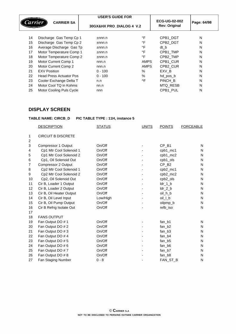
14 Discharge Gas Temp Cp 1 ±nnn.n °F CPB1_DGT N15 Discharge Gas Temp Cp 2 ±nnn.n °F CPB2_DGT N16 Average Discharge Gas Tp ±nnn.n °F dt_b N17 Motor Temperature Comp 1 ±nnn.n °F CPB1_TMP N18 Motor Temperature Comp 2 ±nnn.n °F CPB2_TMP N19 Motor Current Comp 1 nnn.n AMPS CPB1_CUR N20 Motor Current Comp 2 nnn.n AMPS CPB2_CUR N21 EXV Position 0 - 100 % EXV_B N22 Head Press Actuator Pos 0 - 100 % hd_pos_b N23 Cooler Exchange Delta T n.n ^F PINCH_B N24 Motor Cool TQ in Kohms nn.n MTQ_RESB N25 Motor Cooling Puls Cycle nnn CPB1_PUL N
DISPLAY SCREEN
TABLE NAME: CIRCB_D PIC TABLE TYPE : 11H, instance 5
DESCRIPTION STATUS UNITS POINTS FORCEABLE
1 CIRCUIT B DISCRETE23 Compressor 1 Output On/Off - CP_B1 N4 Cp1 Mtr Cool Solenoid 1 On/Off - cpb1_mc1 N5 Cp1 Mtr Cool Solenoid 2 On/Off - cpb1_mc2 N6 Cp1, Oil Solenoid Out On/Off - cpb1_ols N7 Compressor 2 Output On/Off - CP_B2 N8 Cp2 Mtr Cool Solenoid 1 On/Off - cpb2_mc1 N9 Cp2 Mtr Cool Solenoid 2 On/Off - cpb2_mc2 N10 Cp2, Oil Solenoid Out On/Off - cpb2_ols N11 Cir B, Loader 1 Output On/Off - ldr_1_b N12 Cir B, Loader 2 Output On/Off - ldr_2_b N13 Cir B, Oil Heater Output On/Off - oil_h_b N14 Cir B, Oil Level Input Low/High - oil_l_b N15 Cir B, Oil Pump Output On/Off - oilpmp_b N16 Cir B Refrig Isolate Out On/Off - refb_iso N1718 FANS OUTPUT19 Fan Output DO # 1 On/Off - fan_b1 N20 Fan Output DO # 2 On/Off - fan_b2 N21 Fan Output DO # 3 On/Off - fan_b3 N22 Fan Output DO # 4 On/Off - fan_b4 N23 Fan Output DO # 5 On/Off - fan_b5 N24 Fan Output DO # 6 On/Off - fan_b6 N25 Fan Output DO # 7 On/Off - fan_b7 N26 Fan Output DO # 8 On/Off - fan_b8 N27 Fan Staging Number 0 - 8 - FAN_ST_B N
CARRIER SAUSER'S GUIDE FOR
30GX&HX PRO_DIALOG 4 V.2ECG-UG-02-002
Rev: OriginalPage: 64/98
© CARRIER S.ANOT TO BE DISCLOSED TO PERSONS OUTSIDE CARRIER ORGANIZATION

DISPLAY SCREEN
TABLE NAME: OPTIONS PIC TABLE TYPE : 11H, instance 6
DESCRIPTION STATUS UNITS POINTS FORCEABLE
1 UNIT DISCRETE IN2 Remote On/Off Switch Open/Close - onoff_sw N3 Remote Heat/Cool Switch Open/Close - hc_sw N4 Remote Reclaim Switch Open/Close - recl_sw N5 Remote Setpoint Switch Open/Close - setp_sw N6 Limit Switch Status Open/Close - limit_sw N7 Interlock Status Open/Close - lock_1 N8 Pump Run status On/Off - pump_def N9 Condenser Flow Status Open/Close - condflow N10 Electrical Box Thermostat Open/Close4 - elec_box N1112 UNIT DISCRETE OUT13 Cooler Pump #1 Command On/Off1 - CLPUMP_1 Y14 Cooler Pump #2 Command On/Off1 - CLPUMP_2 Y15 Rotate Pumps Now? Yes/No1 - ROT_PUMP Y16 Condenser Pump Command On/Off3 - COND_PMP Y17 Cooler Heater Command On/Off - coolheat N18 Critical Alarm Signal On/Off5 - SAFE_ALM N1920 UNIT ANALOG21 Cooler Entering Fluid ±nnn.n °F COOL_EWT N22 Cooler Leaving Fluid ±nnn.n °F COOL_LWT N23 Condenser Entering Fluid ±nnn.n °F COND_EWT N24 Condenser Leaving Fluid ±nnn.n °F COND_LWT N25 CHWS Temperature ±nnn.n °F CHWSTEMP N26 External 0-10Vdc Signal ±nn.n Volts EXT_VDC N27 Current Cond Setpoint nnn.n2 °F COND_SP Y28 Chiller Total Current nnn.n amps tot_curr N
1: Cooler pump control. This item can be forced On or Off if the unit is in CCN mode and if the CHIL_S_S isdisabled. If the unit is not in CCN mode the forced value shall be unused and the regular calculation shall beused. Forced value and force code shall appear in the OPTIONS Points Display table only if the unit is under CCNcontrol and if CHIL_S_S is disabled. If PUMP#1 is forced, no force shall be allowed on PUMP_2 and vice versa.
2: Condensing Setpoint. This item can be forced. If the unit is in CCN mode, the forced value shall be used insteadof the real control point calculation. If the unit is not in CCN mode the forced value shall be unused and theregular calculation shall be used. Forced value and force code shall appear in the OPTIONS Points Display tableonly if the unit is under CCN control.
3: Condenser pumpcontrol. This item can be forced On but not Off. If the unit is in CCN mode, the forced value shallbe used instead of regular pump control point. If the unit is not in CCN mode the forced value shall be unused andthe regular calculation shall be used. Forced value and force code shall appear in the OPTIONS Points Displaytable only if the unit is under CCN control.
4: Electrical box Thermostat. This item indicates the electrical box thermostat and network power reverse phasedetection status (wired internally in series 16a and 16b on PD4-BASIC BOARD). These contacts, when openedwill prevent the unit from starting.
5: This output is energized when a contact failure is reported by any SCPM board
CARRIER SAUSER'S GUIDE FOR
30GX&HX PRO_DIALOG 4 V.2ECG-UG-02-002
Rev: OriginalPage: 65/98
© CARRIER S.ANOT TO BE DISCLOSED TO PERSONS OUTSIDE CARRIER ORGANIZATION

DISPLAY SCREEN
TABLE NAME: RECLAIM PIC TABLE TYPE : 11H, instance 7
DESCRIPTION STATUS UNITS POINTS FORCEABLE
1 RECLAIM ANALOG PARAM2 Reclaim Entering Fluid ±nnn.n °F HR_EWT N3 Reclaim Leaving Fluid ±nnn.n °F HR_LWT N4 Reclaim Fluid Setpoint ±nnn.n °F hr_sp N5 Cir A SCT Control Point ±nnn.n °F sct_a_sp N6 Cir B SCT Control Point ±nnn.n °F sct_b_sp N7 Cir A Pumpdown Pressure ±nnn.n psi pmpd_p_a N8 Cir B Pumpdown Pressure ±nnn.n psi pmpd_p_b N9 A Saturated Pumpdown Tmp ±nnn.n °F pd_sat_a N10 B Saturated Pumpdown Tmp ±nnn.n °F pd_sat_b N11 HR Cond Valve Position ±nnn.n % hr_v_pos N1213 RECLAIM DISCRETE PARAM - N14 Heat Reclaim Select Yes/No No RECL_SEL N15 Condenser Flow Status Open/Close - condflow N16 Cir A Reclaim Valve Stat On/Off - hr_val_a N17 Cir B Reclaim Valve Stat On/Off - hr_val_b N18 A Pumpdown Valve Status On/Off - pd_val_a N19 B Pumpdown Valve Status On/Off - pd_val_b N20 Circuit A Reclaim Status n hrstat_a N21 Circuit B Reclaim Status n hrstat_b N22 Reclaim Condenser Heater On/Off - cond_htr N
CARRIER SAUSER'S GUIDE FOR
30GX&HX PRO_DIALOG 4 V.2ECG-UG-02-002
Rev: OriginalPage: 66/98
© CARRIER S.ANOT TO BE DISCLOSED TO PERSONS OUTSIDE CARRIER ORGANIZATION

TABLE NAME: MODES PIC TABLE TYPE : 11H, instance 8
DESCRIPTION STATUS UNITS POINTS FORCEABLE
1 OPERATING MODES2 Startup Delay in Effect Yes/No - Mode[07] N3 Second Setpoint in Use Yes/No - Mode[08] N4 Reset in Effect Yes/No - Mode[09] N5 Demand Limit Active Yes/No - Mode[10] N6 Ramp Loading Active Yes/No - Mode[11] N7 Low Source Protection Yes/No - Mode[12] N8 Low Cooler Suction Cir A Yes/No - Mode[13] N9 Low Cooler Suction Cir B Yes/No - Mode[14] N10 Low Dis Superheat Cir A Yes/No - Mode[15] N11 Low Dis Superheat Cir B Yes/No - Mode[16] N12 High Pres Override Cir A Yes/No - Mode[17] N13 High Pres Override Cir B Yes/No - Mode[18] N14 High Current Over Cir A Yes/No - Mode[19] N15 High Current Over Cir B Yes/No - Mode[20] N16 Reclaim Active? Yes/No - Mode[21] N17 Cooler Heater Active? Yes/No - Mode[22] N18 Cooler Pumps Rotation? Yes/No - Mode[23] N19 Pump Periodic Start? Yes/No - Mode[24] N20 Night Capacity Active? Yes/No - Mode[25] N21 System Manager Active? Yes/No - Mode[26] N22 Master Slave Active? Yes/No - Mode[27] N
CARRIER SAUSER'S GUIDE FOR
30GX&HX PRO_DIALOG 4 V.2ECG-UG-02-002
Rev: OriginalPage: 67/98
© CARRIER S.ANOT TO BE DISCLOSED TO PERSONS OUTSIDE CARRIER ORGANIZATION

CONFIGURATION SCREEN
TABLE NAME: USER PIC TABLE TYPE : 10H, instance 2
DESCRIPTION STATUS DEFAULT UNITS POINT
1 USER CONFIGURATION23 Circuit Loading Sequence 0/1/2 0 - lead_cir4 0 = Auto5 1 = Circuit A First6 2 = Circuit B First7 Loading Sequence 0/1 0 - seq_typ89 Ramp Loading Select Yes/No No - ramp_sel1011 Unit Off to On Delay 1 to 15 1 min off_on_d1213 Cooler Pumps Sequence 0/1/2/3/4 0 - pump_seq 14 0 = No Pump15 1 = One Pump Only16 2 = Two Pumps Auto17 3 = Pump#1 Manual18 4 = Pump#2 Manual19 Pump Auto Rotation Delay 24 to 3000 48 hours pump_del20 Periodic Pumps Start Yes/No No - pump_per2122 Reset Type Select 0 to 3 0 - res_sel23 0 = None24 1 = Voltage Control 25 2 = Delta T Control26 3 = OAT Control2728 Demand Limit Type Select 0 to 2 0 - lim_sel29 0 = None30 1 = Switch Control31 2 = 0-10vdc Control32 Vdc For 100% Demand Lim 0 to 10 0 volts lim_mx33 Vdc For 0% Demand Limit 0 to 10 10 volts lim_ze3435 Night Control36 Start Hour 00:00 to 24:00 00:00 - nh_start37 End Hour 00:00 to 24:00 00:00 - nh_end38 Capacity Limit 0 to 100 100 % nh_limit39 Capacity Limit 0 to 100 100 % nh_limit4041 Chiller Comp Current Limit 90 to 15001 1500 amps curr_lim42 Menu Description Select Yes/No Yes - menu_des43 Pass For All User Config Yes/No No - all_pass
1. Refer to control capacity override #35, chiller current limit description
CARRIER SAUSER'S GUIDE FOR
30GX&HX PRO_DIALOG 4 V.2ECG-UG-02-002
Rev: OriginalPage: 68/98
© CARRIER S.ANOT TO BE DISCLOSED TO PERSONS OUTSIDE CARRIER ORGANIZATION
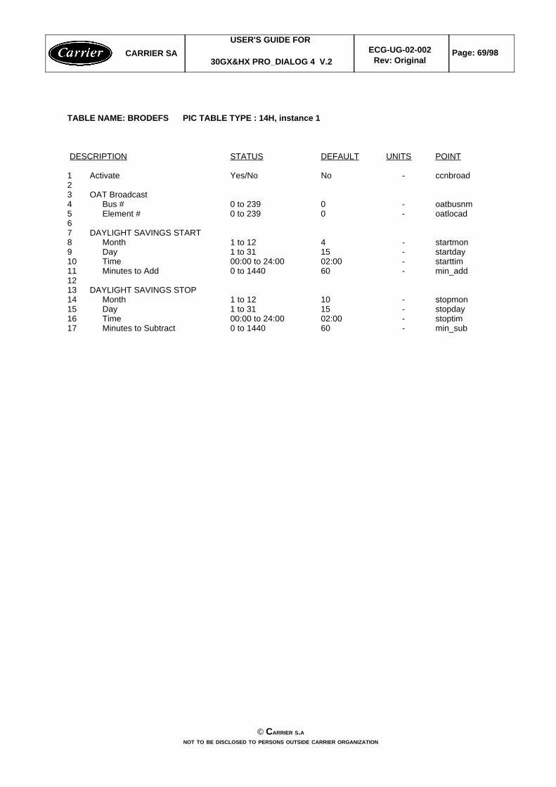
TABLE NAME: BRODEFS PIC TABLE TYPE : 14H, instance 1
DESCRIPTION STATUS DEFAULT UNITS POINT
1 Activate Yes/No No - ccnbroad23 OAT Broadcast4 Bus # 0 to 239 0 - oatbusnm5 Element # 0 to 239 0 - oatlocad67 DAYLIGHT SAVINGS START8 Month 1 to 12 4 - startmon9 Day 1 to 31 15 - startday10 Time 00:00 to 24:00 02:00 - starttim11 Minutes to Add 0 to 1440 60 - min_add1213 DAYLIGHT SAVINGS STOP14 Month 1 to 12 10 - stopmon15 Day 1 to 31 15 - stopday16 Time 00:00 to 24:00 02:00 - stoptim17 Minutes to Subtract 0 to 1440 60 - min_sub
CARRIER SAUSER'S GUIDE FOR
30GX&HX PRO_DIALOG 4 V.2ECG-UG-02-002
Rev: OriginalPage: 69/98
© CARRIER S.ANOT TO BE DISCLOSED TO PERSONS OUTSIDE CARRIER ORGANIZATION

CONFIGURATION SCREEN
TABLE NAME: OCCDEFCS / OCCPC01S and OCCPC02S PIC TABLE TYPE : 14H, instance 2
DESCRIPTION STATUS DEFAULT UNITS POINT
1 Timed Override Hours 0-4 0 - ovr_ext2 Period 1 DOW (MTWTFSSH) 0/1 11111111 - dow13 Occupied From 0:00-24:00 0:00 - occtod14 Occupied To 0:00-24:00 24:00 - unoctod15 Period 2 DOW (MTWTFSSH) 0/1 00000000 - dow26 Occupied From 0:00-24:00 0:00 - occtod27 Occupied To 0:00-24:00 24:00 - unoctod28 Period 3 DOW (MTWTFSSH) 0/1 00000000 - dow39 Occupied From 0:00-24:00 0:00 - occtod310 Occupied To 0:00-24:00 24:00 - unoctod311 Period 4 DOW (MTWTFSSH) 0/1 00000000 - dow412 Occupied From 0:00-24:00 0:00 - occtod413 Occupied To 0:00-24:00 24:00 - unoctod414 Period 5 DOW (MTWTFSSH) 0/1 00000000 - dow515 Occupied From 0:00-24:00 0:00 - occtod516 Occupied To 0:00-24:00 24:00 - unoctod517 Period 6 DOW (MTWTFSSH) 0/1 00000000 - dow618 Occupied From 0:00-24:00 0:00 - occtod619 Occupied To 0:00-24:00 24:00 - unoctod620 Period 7 DOW (MTWTFSSH) 0/1 00000000 - dow721 Occupied From 0:00-24:00 0:00 - occtod722 Occupied To 0:00-24:00 24:00 - unoctod723 Period 8 DOW (MTWTFSSH) 0/1 00000000 - dow824 Occupied From 0:00-24:00 0:00 - occtod825 Occupied To 0:00-24:00 24:00 - unoctod8
TABLE NAME: HOLIDAY / HOLDY01S to HOLDY016S PIC TABLE TYPE : 14H, instance 3
DESCRIPTION STATUS DEFAULT UNITS POINT
Holiday Start Month 0-12 0 - HOL_MONStart Day 0-31 0 - HOL_DAYDuration (days) 0-99 0 - HOL_LEN
CARRIER SAUSER'S GUIDE FOR
30GX&HX PRO_DIALOG 4 V.2ECG-UG-02-002
Rev: OriginalPage: 70/98
© CARRIER S.ANOT TO BE DISCLOSED TO PERSONS OUTSIDE CARRIER ORGANIZATION

SETPOINT SCREEN
TABLE NAME: SETPOINT PIC TABLE TYPE : 17H, instance 1
DESCRIPTION STATUS DEFAULT UNITS POINT
1 COOLING2 Cooling Setpoint 1 - 20 to 101 44.0 °F csp13 Cooling Setpoint 2 - 20 to 101 44.0 °F csp24 Voltage No Reset Value 0 to 10 0.0 volts v_cr_no5 Voltage Full Reset Value 0 to 10 0.0 volts v_cr_fu6 Delta T No Reset Value 0 to 25 0.0 ^F dt_cr_no7 Delta T Full Reset Value 0 to 25 0.0 ^F dt_cr_fu8 OAT No Reset Value 14 to 125 0.0 °F oatcr_no9 OAT Full Reset Value 14 to 125 0.0 °F oatcr_fu10 Cooling Reset Deg. Value -30 to 30 0.0 ^F cr_deg11 Cooling Ramp Loading 0.2 to 2.0 1.0 ^F cramp_sp1213 HEATING14 Heating Setpoint 80 to 153 100.0 °F hsp15 Voltage No Reset Value 0 to 10 0.0 volts v_hr_no16 Voltage Full Reset Value 0 to 10 0.0 volts v_hr_fu17 Delta T No Reset Value 0 to 25 0.0 ^F dt_hr_no18 Delta T Full Reset Value 0 to 25 0.0 ^F dt_hr_fu19 Heating Reset Deg. Value -30 to 30 0.0 ^F hr_deg20 Heating Ramp Loading 0.2 to 2.0 1.0 ^F hramp_sp2122 HEAD PRESSURE23 Sat Cond Temp Setpoint 95 to 1401 104.0 °F headsp24 Reclaim Setpoint 95 to 140 122.0 °F rsp2526 DEMAND LIMIT27 Switch Demand Limit Setp 0 to 100 100 % lim_sp
1 : For water cooled, headsp low limit is 80°F (26.7 degC)
CARRIER SAUSER'S GUIDE FOR
30GX&HX PRO_DIALOG 4 V.2ECG-UG-02-002
Rev: OriginalPage: 71/98
© CARRIER S.ANOT TO BE DISCLOSED TO PERSONS OUTSIDE CARRIER ORGANIZATION

MAINTENANCE SCREEN
TABLE NAME: LOADFACT PIC TABLE TYPE : 12H, instance 1DESCRIPTION STATUS UNITS POINT
1 CAPACITY CONTROL2 Average Ctrl Water Temp ±nnn.n °F ctrl_avg3 Differential Water Temp ±nnn.n °F diff_wt4 Water Delta T ±nnn.n ^F delta_t5 Control Point ±nnn.n °F CTRL_PNT6 Reset Amount ±nnn.n ^F reset7 Controlled Temp Error ±nnn.n ^F tp_error8 Actual Capacity nnn % cap_t9 Actual Capacity Limit nnn % cap_lim10 Current Z Multiplier Val ±n.n - zm11 Load/Unload Factor ±nnn.n - smz12 Active Capacity Override nn - over_cap1314 CIRCUIT A EXV CONTROL15 EXV Position nnn.n % EXV_A16 EXV Position Limit nnn.n % exvlim_a17 Cooler Exchange Delta T n.n ^F PINCH_A18 Discharge Superheat n.n °F DSH_A19 Economizer pinch offset n.n ^F offset_a20 EXV Override nn - ov_exv_a2122 CIRCUIT B EXV CONTROL23 EXV Position nnn.n % EXV_B24 EXV Position Limit nnn.n % exvlim_b25 Cooler Exchange Delta T n.n ^F PINCH_B26 Discharge Superheat n.n °F DSH_B27 Economizer pinch offset n.n ^F offset_b28 EXV Override nn - ov_exv_b
TABLE NAME: LAST_POR PIC TABLE TYPE : 12H, instance 6
1 PowerDown 1:day-mon-year nnnnnn ddmmyy date_of12 PowerDown 1:hour-minute nnnn hhmm time_of13 Power On 2: day-mon-year nnnnnn ddmmyy date_on14 Power On 2: hour-minute nnnn hhmm time_on15 PowerDown 2:day-mon-year nnnnnn ddmmyy date_of26 PowerDown 2:hour-minute nnnn hhmm time_of27 Power On 2: day-mon-year nnnnnn ddmmyy date_on28 Power On 2: hour-minute nnnn hhmm time_on29 PowerDown 3:day-mon-year nnnnnn ddmmyy date_of310 PowerDown 3:hour-minute nnnn hhmm time_of311 Power On 3: day-mon-year nnnnnn ddmmyy date_on312 Power On 3: hour-minute nnnn hhmm time_on313 PowerDown 4:day-mon-year nnnnnn ddmmyy date_of414 PowerDown 4:hour-minute nnnn hhmm time_of415 Power On 4: day-mon-year nnnnnn ddmmyy date_on416 Power On 4: hour-minute nnnn hhmm time_on417 PowerDown 5:day-mon-year nnnnnn ddmmyy date_of518 PowerDown 5:hour-minute nnnn hhmm time_of519 Power On 5: day-mon-year nnnnnn ddmmyy date_on520 Power On 5: hour-minute nnnn hhmm time_on5
CARRIER SAUSER'S GUIDE FOR
30GX&HX PRO_DIALOG 4 V.2ECG-UG-02-002
Rev: OriginalPage: 72/98
© CARRIER S.ANOT TO BE DISCLOSED TO PERSONS OUTSIDE CARRIER ORGANIZATION

MAINTENANCE SCREEN
TABLE NAME: M_MSTSLV PIC TABLE TYPE : 12H, instance 3
DESCRIPTION STATUS UNITS POINT
1 MASTER/SLAVE CONTROL2 Unit is Master or Slave Disable/Master/Slave - mstslv3 Master Control Type Local/Remote/CCN3 - ms_ctrl4 Master/Slave Ctrl Active True/False - ms_activ5 Lead Unit is the: Master/Slave - lead_sel6 Slave Chiller State 0/1/2/3/4/51 - slv_stat7 Slave Chiller Total Cap 0-100 % slv_capt8 Lag Start Delay 1 to 302 minutes l_strt_d9 Lead/Lag Hours Delta ±nnnnn3 hours ll_hr_d10 Lead/Lag Changeover? Yes/No4 - ll_chang11 Lead Pulldown? Yes/No4 - ll_pull12 Master/Slave Error nn - ms_error13 Max Available Capacity ? True/False5 - cap_max
1: Slave chiller chilstat value2: This decision is consistent for Master chiller only. It shall be set by default to 0 for the slave chiller.3: Always CCN for the slave chiller.4: This decision is consistent for Master chiller only. It shall be set by default to 'No' for the slave chiller.5: This item is true when chiller has loaded its total unbroken capacity tonnage.
TABLE NAME: SERMAINT PIC TABLE TYPE : 12H, instance 5
DESCRIPTION STATUS UNITS POINT FORCEABLE
1 Reset Maintenance Alert nn - S_RESET Y2 1 - 11: reset individually3 12 : reset all45 OPERATION WARNINGS6 1 - Refrigerant Charge Normal/Low - charge_m N7 2 - Water Loop Size Normal/Low - wloop_m N8 3 - Air Exchanger Normal/Dirty - aexch_m N1011 GENERAL SERVICING DELAYS12 4 - CPump 1 (days) 0 to 1000/Alert - cpump1_m N13 5 - CPump 2 (days) 0 to 1000/Alert - cpump2_m N14 6 - HPump (days) 0 to 1000/Alert - hpump_m N15 7 - Water Filter (days) 0 to 1000/Alert - wfilte_m N16 8 - A1 Oil Filter (days) 0 to 1000/Alert ofila1_m N17 9 - A2 Oil Filter (days) 0 to 1000/Alert ofila2_m N18 10- B1 Oil Filter (day) 0 to 1000/Alert ofilb1_m N19 11- B2 Oil Filter (days) 0 to 1000/Alert ofilb2_m N
CARRIER SAUSER'S GUIDE FOR
30GX&HX PRO_DIALOG 4 V.2ECG-UG-02-002
Rev: OriginalPage: 73/98
© CARRIER S.ANOT TO BE DISCLOSED TO PERSONS OUTSIDE CARRIER ORGANIZATION
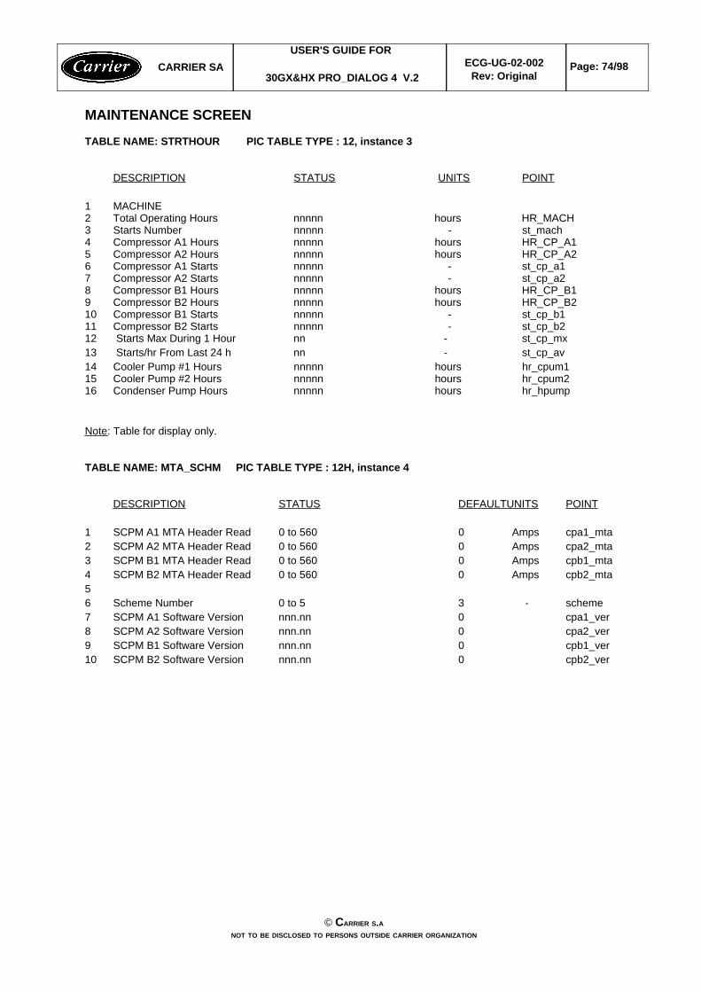
MAINTENANCE SCREEN
TABLE NAME: STRTHOUR PIC TABLE TYPE : 12, instance 3
DESCRIPTION STATUS UNITS POINT
1 MACHINE2 Total Operating Hours nnnnn hours HR_MACH3 Starts Number nnnnn - st_mach4 Compressor A1 Hours nnnnn hours HR_CP_A15 Compressor A2 Hours nnnnn hours HR_CP_A26 Compressor A1 Starts nnnnn - st_cp_a17 Compressor A2 Starts nnnnn - st_cp_a28 Compressor B1 Hours nnnnn hours HR_CP_B19 Compressor B2 Hours nnnnn hours HR_CP_B210 Compressor B1 Starts nnnnn - st_cp_b111 Compressor B2 Starts nnnnn - st_cp_b212 Starts Max During 1 Hour nn - st_cp_mx13 Starts/hr From Last 24 h nn - st_cp_av14 Cooler Pump #1 Hours nnnnn hours hr_cpum115 Cooler Pump #2 Hours nnnnn hours hr_cpum216 Condenser Pump Hours nnnnn hours hr_hpump
Note: Table for display only.
TABLE NAME: MTA_SCHM PIC TABLE TYPE : 12H, instance 4
DESCRIPTION STATUS DEFAULTUNITS POINT
1 SCPM A1 MTA Header Read 0 to 560 0 Amps cpa1_mta2 SCPM A2 MTA Header Read 0 to 560 0 Amps cpa2_mta3 SCPM B1 MTA Header Read 0 to 560 0 Amps cpb1_mta4 SCPM B2 MTA Header Read 0 to 560 0 Amps cpb2_mta56 Scheme Number 0 to 5 3 - scheme7 SCPM A1 Software Version nnn.nn 0 cpa1_ver8 SCPM A2 Software Version nnn.nn 0 cpa2_ver9 SCPM B1 Software Version nnn.nn 0 cpb1_ver10 SCPM B2 Software Version nnn.nn 0 cpb2_ver
CARRIER SAUSER'S GUIDE FOR
30GX&HX PRO_DIALOG 4 V.2ECG-UG-02-002
Rev: OriginalPage: 74/98
© CARRIER S.ANOT TO BE DISCLOSED TO PERSONS OUTSIDE CARRIER ORGANIZATION

TABLE NAME: OCCMAINT PIC TABLE TYPE : 15,
DESCRIPTION STATUS UNITS POINT
1 Current Mode (1=occup.) 0/1 - MODE2 Current Occup Period # 1 to 8 - PER_NO3 Timed -Override in Effect Yes/No - OVERLAST4 Timed-Override Duration 0 to 4 hours OVR_HRS5 Current Occupied Time 00:00 to 23:59 - STRTTIME6 Current Unoccupied Time 00:00 to 23:59 - ENDTIME7 Next Occupied Day Mon to Sun - NXTOCDAY8 Next Occupied Time 00:00 to 23:59 - NXTOCTIM9 Next Unocupied Day Mon to Sun - NXTUNDAY10 Next Unoccupied Time 00:00 to 23:59 - NXTUNTIM11 Prev Unocupied Day Mon to Sun - PRVUNDAY12 Prev Unoccupied Time 00:00 to 23:59 - PRVUNTIM
CARRIER SAUSER'S GUIDE FOR
30GX&HX PRO_DIALOG 4 V.2ECG-UG-02-002
Rev: OriginalPage: 75/98
© CARRIER S.ANOT TO BE DISCLOSED TO PERSONS OUTSIDE CARRIER ORGANIZATION

APPENDIX B
CCN Variables
The following variables can be used for trace functions (Network Service Tool-Trace, Data Collection).
CCN Variables: Hardware SIO Points
cpa2 _mta> 0H-DO-Compressor A2, CommandCP_A2
allH-AI-Compressor A1, status and MTA reading CPA1_STA
allH-AI°FCompressor A1, Motor Temperature CPA1_TMP
allH-AI°FCompressor A1, Discharge Gas TemperatureCPA1_DGT
allH-AIpsiCompressor A1, Economizer PressureCPA1_ECP
allH-AIpsiCompressor A1, Oil PressureCPA1_OP
allH-AIAmpsCompressor A1, Current CPA1_CUR
econ_sel = 1H-AO-Circuit A Motor cooling thermal valve outputCPA1_PUL
AllH-DO-Compressor A1, multiplexed DO'sb5b4b3b2b1b0 b0: cpa1_mc1 Motor cooling 1b1: cpa1_mc2 Motor cooling 2 oreconomizer valveb2: cpa1_ols Oil solenoidb3: cpa1_ld1 Loader 1 outputb4: cpa1_ld2 Loader 2 output b5: oilpmp_a Oil pump output circuit A
CPA1_MUX
allH-DO-Compressor A1, CommandCP_A1
AllH-DOCondenser Water Pump , CommandCONDPUMP
pump_seq > 1H-DOCooler Water Pump # 2, CommandCPUMP_2
pump_seq > 0H-DOCooler Water Pump # 1, CommandCPUMP_1
allH-AI°FCooler leaving water temperatureCOOL_LWT
allH-AI°FCooler entering water temperatureCOOL_EWT
unit_typ = 2 or 3 H-AI°FCondenser leaving water temperatureCOND_LWT
unit_typ = 2 or 3H-AI°FCondenser entering water temperatureCOND_EWT
AllH-AI°FChiller Water System for Master / Slave ControlCHWSTEMP
cpb1_mta > 0H-DOCircuit B Alarm Relay, CommandALARM_B
allH-DOCircuit A Alarm Relay, CommandALARM_A
CONFIGURATIONTYPEUNITSDESCRIPTIONSPOINTNAMES
CARRIER SAUSER'S GUIDE FOR
30GX&HX PRO_DIALOG 4 V.2ECG-UG-02-002
Rev: OriginalPage: 76/98
© CARRIER S.ANOT TO BE DISCLOSED TO PERSONS OUTSIDE CARRIER ORGANIZATION

cb2_mta> 0H-AIpsiCompressor B2, Oil PressureCPB2_OP
cb2_mta> 0H-AIAmpsCompressor B2, Current CPB2_CUR
cb2_mta > 0H-DO-Compressor B2, multiplexed DO'sb5b4b3b2b1b0 b0: cpb2_mc1 Motor cooling 1b1: cpb2_mc2 Motor cooling 2 oreconomizer valveb2: cpb2_ols Oil solenoidb3: cpb2_ld1 Loader 1 outputb4: cpb2_ld2 Loader 2 output b5: not used
CPB2_MUX
cpb2_mta> 0H-DO-Compressor B2, CommandCP_B2
cpb1_mta> 0H-AI-Compressor B1, status and MTA reading CPB1_STAT
cpb1_mta > 0H-AI°FCompressor B1, Motor Temperature CPB1_TMP
cpb1_mta> 0H-AI°FCompressor B1, Discharge Gas TemperatureCPB1_DGT
cpb1_mta > 0H-AIpsiCompressor B1, Economizer PressureCPB1_ECP
cpb1_mta > 0H-AIpsiCompressor B1, Oil PressureCPB1_OP
cpb1_mta > 0H-AIAmpsCompressor B1, Current CPB1_CUR
cpb1_mta> 0 andecon_sel = 1
H-AO-Circuit B Motor cooling thermal valve outputCPB1_PUL
cpb1_mta > 0H-DO-Compressor B1, multiplexed DO'sb5b4b3b2b1b0 b0: cpb1_mc1 Motor cooling 1b1: cpb1_mc2 Motor cooling 2 oreconomizer valveb2: cpb1_ols Oil solenoidb3: cpb1_ld1 Loader 1 outputb4: cpb1_ld2 Loader 2 output b5: oilpmp_b Oil pump output circuit B
CPB1_MUX
cpb1_mta> 0H-DO-Compressor B1, CommandCP_B1
cpa2_mta> 0H-AI-Compressor A2, status and MTA reading CPA2_STA
cpa2_mta> 0H-AI°FCompressor A2, Motor Temperature CPA2_TMP
cpa2_mta> 0H-AI°FCompressor A2, Discharge Gas TemperatureCPA2_DGT
cpa2_mta > 0 andecon_sel = 0
H-AIpsiCompressor A2, Economizer PressureCPA2_ECP
cpa2_mta> 0H-AIpsiCompressor A2, Oil PressureCPA2_OP
cpa2_mta > 0H-AIAmpsCompressor A2, Current CPA2_CUR
cpa2_mta > 0H-DO-Compressor A2, multiplexed DO'sb5b4b3b2b1b0 b0: cpa2_mc1 Motor cooling 1b1: cpa2_mc2 Motor cooling 2 oreconomizer valveb2: cpa2_ols Oil solenoidb3: cpa2_ld1 Loader 1 outputb4: cpa2_ld2 Loader 2 output b5: not used
CPA2_MUX
CONFIGURATIONTYPEUNITSDESCRIPTIONSPOINTNAMES
CARRIER SAUSER'S GUIDE FOR
30GX&HX PRO_DIALOG 4 V.2ECG-UG-02-002
Rev: OriginalPage: 77/98
© CARRIER S.ANOT TO BE DISCLOSED TO PERSONS OUTSIDE CARRIER ORGANIZATION

all
(all)(all)
(unit_typ = 3)(unit_typ = 1 or 4)
(all)(all)(all)(all)
(uni_typ = 1 or 4)
H-DIM-Basic board multilexed DI's:b7b6b5b4b3b2b1b0
b0: onoff_sw Remote on/off switchb1: spt_sw Remote dual setpoint swb2: hc_sw Remote heat/cool switchb2: recl_sw Remote reclaim swutchb3: limit_sw demand limit switch b4: lock_1 Cooler interlock b5: elec_box Electrical Box Thermostatb6: condflow Condenser flow switchb7: pump_def Pump default
MUX_DI
econ_sel and tq_r_fbk=YES
H-AI-Motor Cooling Feedback Signal circuit B MTQ_RESB
econ_sel and tq_r_fbk=YES
H-AI-Motor Cooling Feedback Signal circuit A MTQ_RESA
recl_opt = 1H-AO0 -10Vdc
Reclaim Condenser Water ValveHR_WTRVL
hr_tmp = 1H-AI°FReclaim Entering Water TemperatureHR_LWT
hr_tmp = 1H-AI°FReclaim Entering Water TemperatureHR_EWT
hd_selec > 0H-AO4 - 20mA0 -
10Vdc
Varifan or Water Valve Circuit BHD_B
hd_selec > 0H-AO4 - 20mA0 -
10Vdc
Varifan or Water Valve Circuit AHD_A
cb2_mta> 0H-AIpsiDischarge Pressure Circuit BDP_B
allH-AIpsiDischarge Pressure Circuit ADP_A
allH-AIvoltsExternal 0 - 10 Vdc input sensor EXT_VDC
cb2_mta > 0H-AO%EXV Movement Circuit BEXV_ST_B
allH-AO%EXV Movement Circuit AEXV_ST_A
cb2_mta> 0H-AI-Compressor B2, status and MTA reading CPB2_STA
cb2_mta> 0H-AI°FCompressor B2, Motor Temperature CPB2_TMP
cb2_mta> 0H-AI°FCompressor B2, Discharge Gas TemperatureCPB2_DGT
cb2_mta > 0 andecon_sel = 0
H-AIpsiCompressor B2, Economizer PressureCPB2_ECP
CONFIGURATIONTYPEUNITSDESCRIPTIONSPOINTNAMES
CARRIER SAUSER'S GUIDE FOR
30GX&HX PRO_DIALOG 4 V.2ECG-UG-02-002
Rev: OriginalPage: 78/98
© CARRIER S.ANOT TO BE DISCLOSED TO PERSONS OUTSIDE CARRIER ORGANIZATION
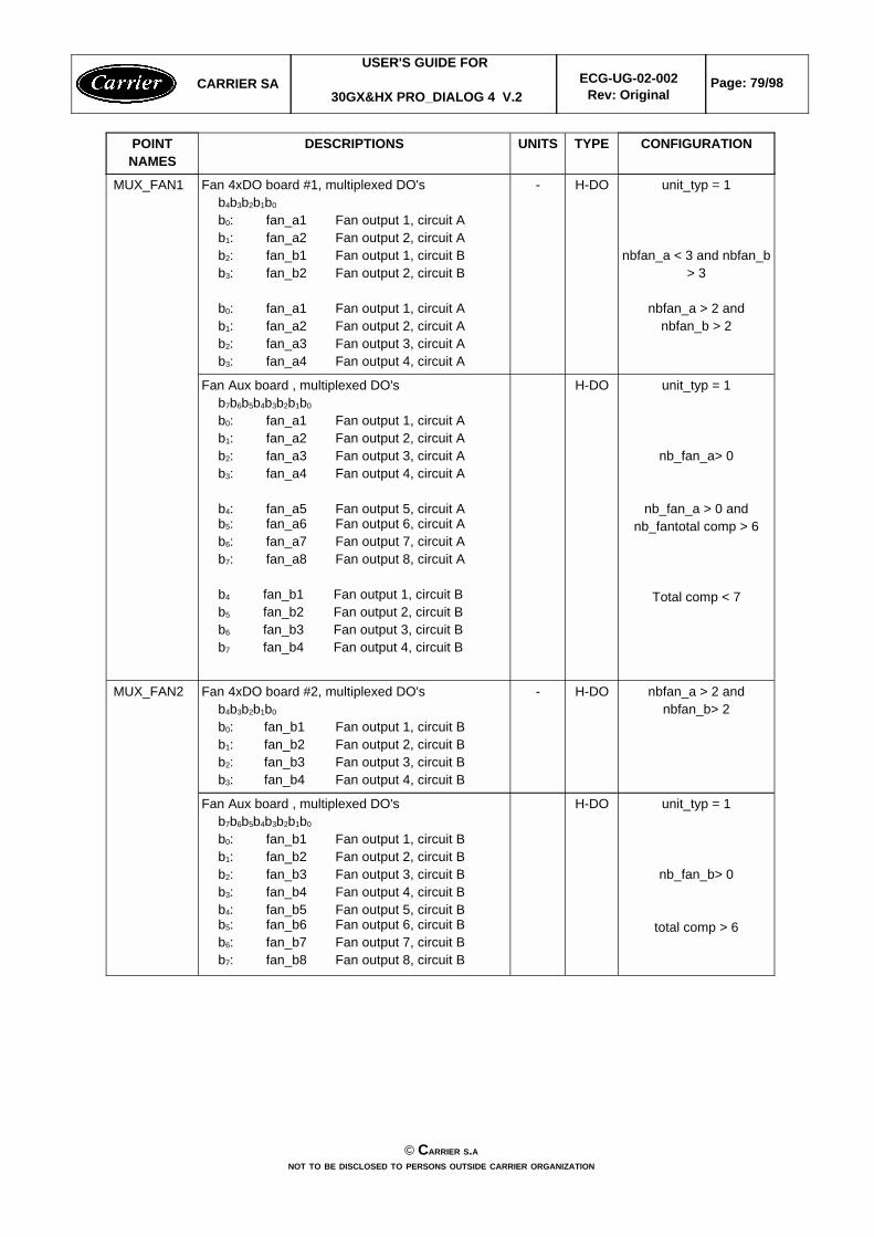
unit_typ = 1
nb_fan_b> 0
total comp > 6
H-DOFan Aux board , multiplexed DO'sb7b6b5b4b3b2b1b0 b0: fan_b1 Fan output 1, circuit Bb1: fan_b2 Fan output 2, circuit Bb2: fan_b3 Fan output 3, circuit Bb3: fan_b4 Fan output 4, circuit Bb4: fan_b5 Fan output 5, circuit Bb5: fan_b6 Fan output 6, circuit Bb6: fan_b7 Fan output 7, circuit Bb7: fan_b8 Fan output 8, circuit B
nbfan_a > 2 andnbfan_b> 2
H-DO-Fan 4xDO board #2, multiplexed DO'sb4b3b2b1b0 b0: fan_b1 Fan output 1, circuit Bb1: fan_b2 Fan output 2, circuit Bb2: fan_b3 Fan output 3, circuit Bb3: fan_b4 Fan output 4, circuit B
MUX_FAN2
unit_typ = 1
nb_fan_a> 0
nb_fan_a > 0 andnb_fantotal comp > 6
Total comp < 7
H-DOFan Aux board , multiplexed DO'sb7b6b5b4b3b2b1b0 b0: fan_a1 Fan output 1, circuit Ab1: fan_a2 Fan output 2, circuit Ab2: fan_a3 Fan output 3, circuit Ab3: fan_a4 Fan output 4, circuit A
b4: fan_a5 Fan output 5, circuit Ab5: fan_a6 Fan output 6, circuit Ab6: fan_a7 Fan output 7, circuit Ab7: fan_a8 Fan output 8, circuit A
b4 fan_b1 Fan output 1, circuit Bb5 fan_b2 Fan output 2, circuit Bb6 fan_b3 Fan output 3, circuit Bb7 fan_b4 Fan output 4, circuit B
unit_typ = 1
nbfan_a < 3 and nbfan_b> 3
nbfan_a > 2 andnbfan_b > 2
H-DO-Fan 4xDO board #1, multiplexed DO'sb4b3b2b1b0 b0: fan_a1 Fan output 1, circuit Ab1: fan_a2 Fan output 2, circuit Ab2: fan_b1 Fan output 1, circuit Bb3: fan_b2 Fan output 2, circuit B
b0: fan_a1 Fan output 1, circuit Ab1: fan_a2 Fan output 2, circuit Ab2: fan_a3 Fan output 3, circuit Ab3: fan_a4 Fan output 4, circuit A
MUX_FAN1
CONFIGURATIONTYPEUNITSDESCRIPTIONSPOINTNAMES
CARRIER SAUSER'S GUIDE FOR
30GX&HX PRO_DIALOG 4 V.2ECG-UG-02-002
Rev: OriginalPage: 79/98
© CARRIER S.ANOT TO BE DISCLOSED TO PERSONS OUTSIDE CARRIER ORGANIZATION

alllH-DO-Critical Alarm Signal, CommandSAFE_ALM
allH-AIPSISuction pressure, circuit BSP_B
allH-AIPSISuction pressure, circuit ASP_A
recl_opt = yes andcpb1_mta > 0
H-AIPSIReclaim Pumpdown Pressure circuit BPD_P_B
recl_opt = yesH-AIPSIReclaim Pumpdown Pressure circuit APD_P_A
unit_typ = 1 or 4 andcpb1_mta > 0
H-DOOil Heater Circuit BOIL_HTRB
unit_typ = 1 or 4H-DOOil Heater Circuit AOIL_HTRA
unit_typ = 1 or 4H-AI°FOutside Air TemperatureOAT
heat_sel = yes orrecl_opt = yesrecl_opt = yesrecl_opt = yes
recl_opt = yesrecl_opt = yesrecl_opt = yes
(heat_sel = yes)(heat_sel = yes)(heat_sel = yes)
H-DOM-NRCP (AQUASNAP) Basic board multilexed DO's,or AUX 1 Basic board multilexed DO's:
b9b8b7b6b5b4b3b2b1b0
b0: hr_val_a reclaim valve circuit Ab1: hr_val_b reclaim valve circuit Bb2: unusedb3: cond_htr reclaim condenser heaterb4: pd_val_a pumpdown valve circuit Ab5: pd_val_b pumpdown valve circuit Bb6: unusedb7: cool_htr cooler heaterb8: refa_iso refriegerant solenoid Ab9: refb_iso refriegerant solenoid B
MUX_HRDO
CONFIGURATIONTYPEUNITSDESCRIPTIONSPOINTNAMES
CARRIER SAUSER'S GUIDE FOR
30GX&HX PRO_DIALOG 4 V.2ECG-UG-02-002
Rev: OriginalPage: 80/98
© CARRIER S.ANOT TO BE DISCLOSED TO PERSONS OUTSIDE CARRIER ORGANIZATION

CCN Variables: Software SIO Points
S-A°FLeaving Water TemperatureLWT
S-A°FCCN Leaving Chiller Water SetpointLCW_STPT
S-A%Master Slave Lag limitLAG_LIM
S-AHoursCompressor B2 Run time Operation HR_CP_B2
S-AHoursCompressor B1 Run time Operation HR_CP_B1
S-AHoursCompressor A2 Run time Operation HR_CP_A2
S-AHoursCompressor A1 Run time Operation HR_CP_A1
S-AHoursChiller Run time Operation HR_MACH
S-A-Heat/Cool Select ( 0=Cool 1= Heat )HC_SEL
S-AFan stages Circuit BFAN_ST_B
S-AFan stages Circuit AFAN_ST_A
S-A%EXV Position Circuit BEXV_B
S-A%EXV Position Circuit AEXV_A
S-A°FEntering Water TemperatureEWT
S-D-Emergency Stop Enable/Disable via CCN flagEMSTOP
S-ApsiCompressor B2, Oil Differential Pressure DOP_B2
S-ApsiCompressor B1, Oil Differential Pressure DOP_B1
S-ApsiCompressor A2, Oil Differential Pressure DOP_A2
S-ApsiCompressor A1, Oil Differential Pressure DOP_A1
S-A^FDischarge Superheat Circuit BDSH_B
S-A^FDischarge Superheat Circuit ADSH_A
S-APercentActive Demand Limit ValueDEM_LIM
S-A°FChiller Control Water CTRL_WT
S-A°FChille Control PointCTRL_PNT
S-D-Cooler heater outputCOOLHEAT
S-A°FConsensing SetpointCOND_SP
S-D-Condenser pump statusCOND_PMP
S-D-Cooler pump # 2 statusCL_PUMP2
S-D-Cooler pump # 1 statusCL_PUMP1
S-D-CCN Enable/Disable the start/Stop Chiller FlagCHIL_S_S
S-D-CCN Chiller Occupancy FlagCHIL_OCC
S-D-CCN Chiller status (for SM & Master/Slave operation )CHILSTAT
S-APercentChiller Available Percent Capacity (running or not)CAP_T_AV
S-APercentMachine Percent CapacityCAP_T
S-APercentCircuit B Percent CapacityCAPB_T
S-APercentCircuit A Percent CapacityCAPA_T
S-AI-Alarm Status (0=no alarm 1=partial alarm 2=total alarm) ALM
TYPEUNITSDESCRIPTIONSPOINT NAMES
CARRIER SAUSER'S GUIDE FOR
30GX&HX PRO_DIALOG 4 V.2ECG-UG-02-002
Rev: OriginalPage: 81/98
© CARRIER S.ANOT TO BE DISCLOSED TO PERSONS OUTSIDE CARRIER ORGANIZATION

S-A-Circuit A & B Oil level indicator : 3 = Circuit A & Circuit B oil level are both high2 = Circuit A oil level is high, circuit B oil level is low1 = Circuit A oil level is low, circuit B oil level is high0 = Circuit A & Circuit B oil level are both low
TOT_OIL
S-A-Unit state information (int value):
1 = local operating type, off mode2 = local operating type, on mode3 = remote operating type, off mode4 = remote operating type, on mode5 = ccn operating type, off mode6 = ccn operating type, on mode7 = ccn operating type, off mode, system manager control8 = ccn operating type, on mode, system manager control9 = Master operating type, off mode10 = Master operating type, on mode11 = Master operating type, Master Slave Control, off mode12 = Master operating type, Master Slave Control, on modeoff mode = unit is commended to OFF or totally failedon mode = unit is commended to ON (status could also bedelay)
STATE
S-A°FSaturated Suction Temperature, Circuit BSST_B
S-A°FSaturated Suction Temperature, Circuit ASST_A
S-DSetpoint occupancy statusSP_OCC
S-A-Sum/Z Value for capacity PID Loop ControlSMZ
S-A°FSaturated Condensing Temperature, Circuit BSCT_B
S-A°FSaturated Condensing Temperature, Circuit ASCT_AS-D-Servicing alert ResetS RESETS-D-Rotate pumps nowROT PUMP
S-D-Reclaim SelectRECL_SEL
S-A^FCooler Exchange Deltat T circuit BPINCH_B
S-A^FCooler Exchange Deltat T circuit APINCH_A
S-AminMinutes left for startMIN_LEFT
TYPEUNITSDESCRIPTIONSPOINT NAMES
CARRIER SAUSER'S GUIDE FOR
30GX&HX PRO_DIALOG 4 V.2ECG-UG-02-002
Rev: OriginalPage: 82/98
© CARRIER S.ANOT TO BE DISCLOSED TO PERSONS OUTSIDE CARRIER ORGANIZATION

SCHEME 1 : Water Cooled Chillers 1 compressor, Aux Board
Channel 27-28: virtual
-AIChannel 38-MTQ RESAAIChannel 37-Channel 33EXV ST AChannel 29
EXV BOARD #1Address = 29
SAFE ALMDOChannel 26DOChannel 25
ALARM ADOChannel 24-DOChannel 23-DOChannel 22CONDPUMPDOChannel 21CPUMP 2DOChannel 20CPUMP 1DOChannel 19pump_defDI11 - bit 7cond_flowDI11 - bit 6
-AIChannel 94elec boxDI11 - bit 5 -AIChannel 93lock 1DI11 - bit 4
-AIChannel 55CPA1 STAAIChannel 92lim swDI11 - bit 3-AIChannel 54CPA1 TMPAIChannel 91hc swDI11 - bit 2-AIChannel 53CPA1 DGTAIChannel 90spt swDI11 - bit 1-AIChannel 52CPA1 ECPAIChannel 89onoff swDI11- bit 0
AOChannel 51CPA1 OPAIChannel 88MUX DI 1Channel 11HD AAOChannel 50CPA1 CURAIChannel 87EXT VDCAIChannel 10-DOCh 49 bit-7CPA1 PULDOChannel 86AIChannel 09-DOCh 49 bit-6oilpmp aDO85 - bit 5AIChannel 08-DOCh 49 bit-5a1 ldr 2DO85 - bit 4SP AAIChannel 07-DOCh 49 bit-4a1 ldr 1DO85 - bit 3DP AAIChannel 06-DOCh 49 bit-3cpa1 olsDO85 - bit 2COND EWTAIChannel 05-DOCh 49 bit-2cpa1 mc2DO85 - bit 1COND LWTAIChannel 04-DOCh 49 bit-1cpa1 mc1DO85 - bit 0CHWSTEMPAIChannel 03-DOCh 49 bit-0CPA1 MUXChannel 85COOL EWTAIChannel 02-Channel 49CP A1DOChannel 84COOL LWTAIChannel 01
AUXILIARY BOARD # 1 Address = 49
SCPM BOARD #1Address =84
BASIC BOARDAddress = 1
CARRIER SA USER’S GUIDE FOR 30GX&HX PRO_DIALOG 4 V.2
ECG-UG-02-002Rev: Original
Page: 83 / 98
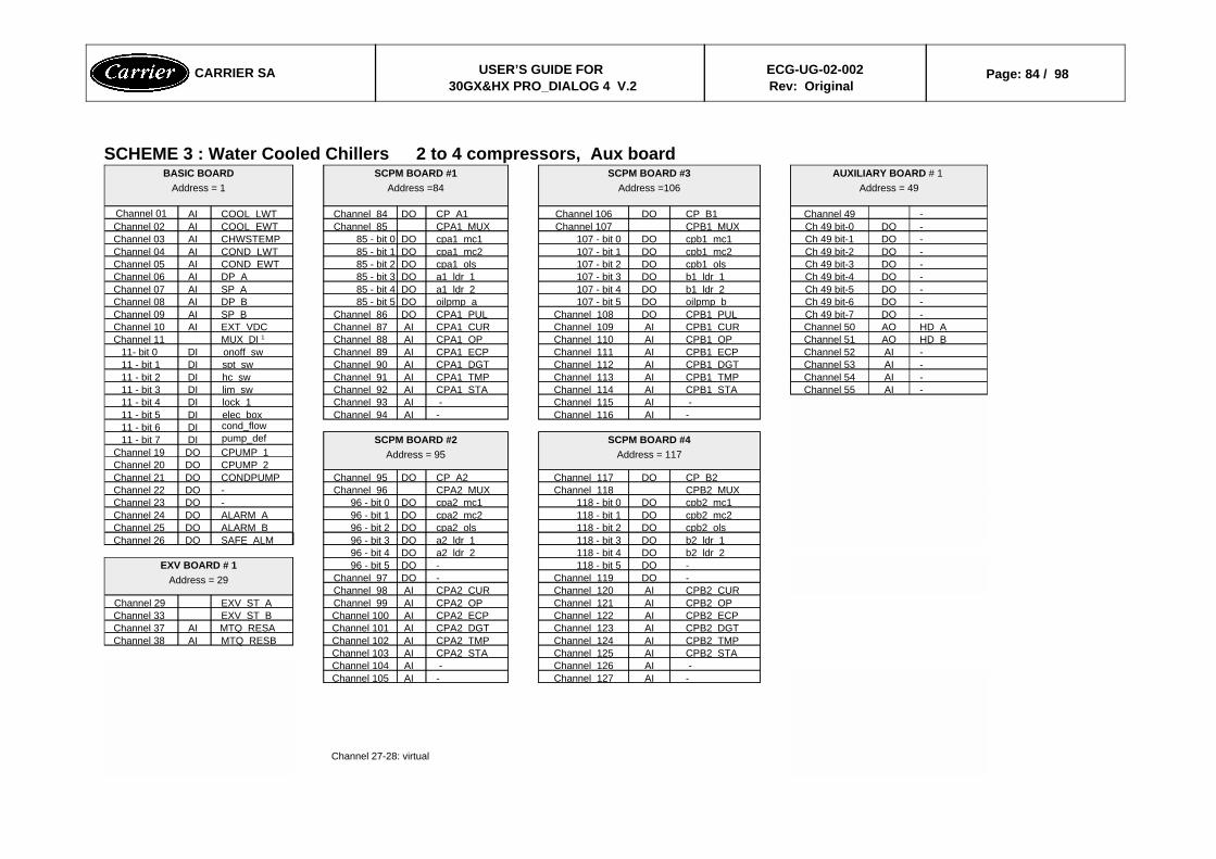
SCHEME 3 : Water Cooled Chillers 2 to 4 compressors, Aux board
Channel 27-28: virtual
-AIChannel 127-AIChannel 105 -AIChannel 126 -AIChannel 104CPB2 STAAIChannel 125CPA2 STAAIChannel 103CPB2 TMPAIChannel 124CPA2 TMPAIChannel 102MTQ RESBAIChannel 38CPB2 DGTAIChannel 123CPA2 DGTAIChannel 101MTQ RESAAIChannel 37CPB2 ECPAIChannel 122CPA2 ECPAIChannel 100EXV ST BChannel 33CPB2 OPAIChannel 121CPA2 OPAIChannel 99EXV ST AChannel 29CPB2 CURAIChannel 120CPA2 CURAIChannel 98-DOChannel 119-DOChannel 97-DO118 - bit 5-DO96 - bit 5EXV BOARD # 1
Address = 29
b2 ldr 2DO118 - bit 4a2 ldr 2DO96 - bit 4b2 ldr 1DO118 - bit 3a2 ldr 1DO96 - bit 3SAFE ALMDOChannel 26cpb2 olsDO118 - bit 2cpa2 olsDO96 - bit 2ALARM BDOChannel 25cpb2 mc2DO118 - bit 1cpa2 mc2DO96 - bit 1ALARM ADOChannel 24cpb2 mc1DO118 - bit 0cpa2 mc1DO96 - bit 0-DOChannel 23CPB2 MUXChannel 118CPA2 MUXChannel 96-DOChannel 22CP B2DOChannel 117CP A2DOChannel 95CONDPUMPDOChannel 21
CPUMP 2DOChannel 20CPUMP 1DOChannel 19
SCPM BOARD #4Address = 117
SCPM BOARD #2Address = 95
pump_defDI11 - bit 7cond_flowDI11 - bit 6
-AIChannel 116-AIChannel 94elec boxDI11 - bit 5 -AIChannel 115 -AIChannel 93lock 1DI11 - bit 4
-AIChannel 55CPB1 STAAIChannel 114CPA1 STAAIChannel 92lim swDI11 - bit 3-AIChannel 54CPB1 TMPAIChannel 113CPA1 TMPAIChannel 91hc swDI11 - bit 2-AIChannel 53CPB1 DGTAIChannel 112CPA1 DGTAIChannel 90spt swDI11 - bit 1-AIChannel 52CPB1 ECPAIChannel 111CPA1 ECPAIChannel 89onoff swDI11- bit 0HD BAOChannel 51CPB1 OPAIChannel 110CPA1 OPAIChannel 88MUX DI 1Channel 11HD AAOChannel 50CPB1 CURAIChannel 109CPA1 CURAIChannel 87EXT VDCAIChannel 10-DOCh 49 bit-7CPB1 PULDOChannel 108CPA1 PULDOChannel 86SP BAIChannel 09-DOCh 49 bit-6oilpmp bDO107 - bit 5oilpmp aDO85 - bit 5DP BAIChannel 08-DOCh 49 bit-5b1 ldr 2DO107 - bit 4a1 ldr 2DO85 - bit 4SP AAIChannel 07-DOCh 49 bit-4b1 ldr 1DO107 - bit 3a1 ldr 1DO85 - bit 3DP AAIChannel 06-DOCh 49 bit-3cpb1 olsDO107 - bit 2cpa1 olsDO85 - bit 2COND EWTAIChannel 05-DOCh 49 bit-2cpb1 mc2DO107 - bit 1cpa1 mc2DO85 - bit 1COND LWTAIChannel 04-DOCh 49 bit-1cpb1 mc1DO107 - bit 0cpa1 mc1DO85 - bit 0CHWSTEMPAIChannel 03-DOCh 49 bit-0CPB1 MUXChannel 107CPA1 MUXChannel 85COOL EWTAIChannel 02-Channel 49CP B1DOChannel 106CP A1DOChannel 84COOL LWTAIChannel 01
AUXILIARY BOARD # 1 Address = 49
SCPM BOARD #3Address =106
SCPM BOARD #1Address =84
BASIC BOARDAddress = 1
CARRIER SA USER’S GUIDE FOR 30GX&HX PRO_DIALOG 4 V.2
ECG-UG-02-002Rev: Original
Page: 84 / 98

SCHEME 4 : Water Cooled Chillers 2 to 4 Compressors, no Aux Board
HD BAOChannel 52-HD AAOChannel 51-Channel 27-28: virtual -AIChannel 50
-AIChannel 49-AIChannel 48-AIChannel 47
- -AIChan126-127 -AIChan104-1054xAI - 2xAO BOARD
Address = 47
CPB2 STAAIChannel 125CPA2 STAAIChannel 103CPB2 TMPAIChannel 124CPA2 TMPAIChannel 102MTQ RESBAIChannel 38CPB2 DGTAIChannel 123CPA2 DGTAIChannel 101MTQ RESAAIChannel 37CPB2 ECPAIChannel 122CPA2 ECPAIChannel 100EXV ST BChannel 33CPB2 OPAIChannel 121CPA2 OPAIChannel 99EXV ST AChannel 29CPB2 CURAIChannel 120CPA2 CURAIChannel 98-DOChannel 119-DOChannel 97-DO118 - bit 5-DO96 - bit 5EXV BOARD # 1
Address = 29
b2 ldr 2DO118 - bit 4a2 ldr 2DO96 - bit 4b2 ldr 1DO118 - bit 3a2 ldr 1DO96 - bit 3SAFE ALMDOChannel 26cpb2 olsDO118 - bit 2cpa2 olsDO96 - bit 2ALARM BDOChannel 25cpb2 mc2DO118 - bit 1cpa2 mc2DO96 - bit 1ALARM ADOChannel 24cpb2 mc1DO118 - bit 0cpa2 mc1DO96 - bit 0-DOChannel 23CPB2 MUXChannel 118CPA2 MUXChannel 96-DOChannel 22CP B2DOChannel 117CP A2DOChannel 95CONDPUMPDOChannel 21
CPUMP 2DOChannel 20CPUMP 1DOChannel 19
SCPM BOARDAddress = 117
SCPM BOARDAddress = 40
pump_defDI11 - bit 7cond_flowDI11 - bit 6
--elec boxDI11 - bit 5 -AIChan 115-16 -AIChan 93-94lock 1DI11 - bit 4CPB1 STAAIChannel 114CPA1 STAAIChannel 92lim swDI11 - bit 3CPB1 TMPAIChannel 113CPA1 TMPAIChannel 91hc swDI11 - bit 2CPB1 DGTAIChannel 112CPA1 DGTAIChannel 90spt swDI11 - bit 1CPB1 ECPAIChannel 111CPA1 ECPAIChannel 89onoff swDI11- bit 0CPB1 OPAIChannel 110CPA1 OPAIChannel 88MUX DI 1Channel 11CPB1 CURAIChannel 109CPA1 CURAIChannel 87EXT VDCAIChannel 10CPB1 PULDOChannel 108CPA1 PULDOChannel 86SP BAIChannel 09oilpmp bDO107 - bit 5oilpmp aDO85 - bit 5DP BAIChannel 08b1 ldr 2DO107 - bit 4a1 ldr 2DO85 - bit 4SP AAIChannel 07b1 ldr 1DO107 - bit 3a1 ldr 1DO85 - bit 3DP AAIChannel 06cpb1 olsDO107 - bit 2cpa1 olsDO85 - bit 2COND EWTAIChannel 05cpb1 mc2DO107 - bit 1cpa1 mc2DO85 - bit 1COND LWTAIChannel 04cpb1 mc1DO107 - bit 0cpa1 mc1DO85 - bit 0CHWSTEMPAIChannel 03CPB1 MUXChannel 107CPA1 MUXChannel 85COOL EWTAIChannel 02CP B1DOChannel 106CP A1DOChannel 84COOL LWTAIChannel 01
SCPM BOARDAddress = 106
SCPM BOARDAddress = 84
BASIC BOARDAddress = 1
CARRIER SA USER’S GUIDE FOR 30GX&HX PRO_DIALOG 4 V.2
ECG-UG-02-002Rev: Original
Page: 85 / 98
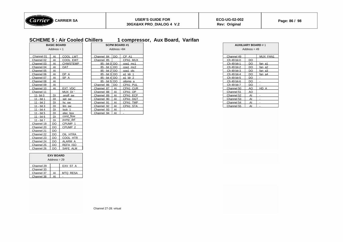
SCHEME 5 : Air Cooled Chillers 1 compressor, Aux Board, Varifan
Channel 27-28: virtual
-AIChannel 38MTQ RESAAIChannel 37
Channel 33EXV ST AChannel 29
EXV BOARDAddress = 29
SAFE ALMDOChannel 26REFA ISODOChannel 25ALARM ADOChannel 24COOL HTRDOChannel 23OIL HTRADOChannel 22
DOChannel 21CPUMP 2DOChannel 20CPUMP 1DOChannel 19pump_defDI11 - bit 7cond_flowDI11 - bit 6
-AIChannel 94elec boxDI11 - bit 5 -AIChannel 93lock 1DI11 - bit 4
-AIChannel 55CPA1 STAAIChannel 92lim swDI11 - bit 3-AIChannel 54CPA1 TMPAIChannel 91hc swDI11 - bit 2-AIChannel 53CPA1 DGTAIChannel 90spt swDI11 - bit 1-AIChannel 52CPA1 ECPAIChannel 89onoff swDI11- bit 0
AOChannel 51CPA1 OPAIChannel 88MUX DI 1Channel 11HD AAOChannel 50CPA1 CURAIChannel 87EXT VDCAIChannel 10-DOCh 49 bit-7CPA1 PULDOChannel 86AIChannel 09-DOCh 49 bit-6oilpmp aDO85 - bit 5AIChannel 08-DOCh 49 bit-5a1 ldr 2DO85 - bit 4SP AAIChannel 07fan a4DOCh 49 bit-4a1 ldr 1DO85 - bit 3DP AAIChannel 06fan a3DOCh 49 bit-3cpa1 olsDO85 - bit 2AIChannel 05fan a2DOCh 49 bit-2cpa1 mc2DO85 - bit 1OATAIChannel 04fan a1DOCh 49 bit-1cpa1 mc1DO85 - bit 0CHWSTEMPAIChannel 03
DOCh 49 bit-0CPA1 MUXChannel 85COOL EWTAIChannel 02MUX FAN1Channel 49CP A1DOChannel 84COOL LWTAIChannel 01
AUXILIARY BOARD # 1 Address = 49
SCPM BOARD #1Address =84
BASIC BOARDAddress = 1
CARRIER SA USER’S GUIDE FOR 30GX&HX PRO_DIALOG 4 V.2
ECG-UG-02-002Rev: Original
Page: 86 / 98

SCHEME 6 : Air Cooled Chillers 1 compressor, Aux Board, No Varifan
Channel 27-28: virtual
-AIChannel 38MTQ RESAAIChannel 37
Channel 33EXV ST AChannel 29
EXV BOARDAddress = 29
SAFE ALMDOChannel 26REFA ISODOChannel 25ALARM ADOChannel 24COOL HTRDOChannel 23OIL HTRADOChannel 22
DOChannel 21CPUMP 2DOChannel 20CPUMP 1DOChannel 19pump_defDI11 - bit 7cond_flowDI11 - bit 6
-AIChannel 94elec boxDI11 - bit 5 -AIChannel 93lock 1DI11 - bit 4CPA1 STAAIChannel 92lim swDI11 - bit 3CPA1 TMPAIChannel 91hc swDI11 - bit 2CPA1 DGTAIChannel 90spt swDI11 - bit 1CPA1 ECPAIChannel 89onoff swDI11- bit 0CPA1 OPAIChannel 88MUX DI 1Channel 11CPA1 CURAIChannel 87EXT VDCAIChannel 10
-DOCh 49 bit-7CPA1 PULDOChannel 86AIChannel 09-DOCh 49 bit-6oilpmp aDO85 - bit 5AIChannel 08-DOCh 49 bit-5a1 ldr 2DO85 - bit 4SP AAIChannel 07-DOCh 49 bit-4a1 ldr 1DO85 - bit 3DP AAIChannel 06fan a4DOCh 49 bit-3cpa1 olsDO85 - bit 2AIChannel 05fan a3DOCh 49 bit-2cpa1 mc2DO85 - bit 1OATAIChannel 04fan a2DOCh 49 bit-1cpa1 mc1DO85 - bit 0CHWSTEMPAIChannel 03fan a1DOCh 49 bit-0CPA1 MUXChannel 85COOL EWTAIChannel 02MUX FAN1Channel 49CP A1DOChannel 84COOL LWTAIChannel 01
AUXILIARY BOARD # 1 Address = 49
SCPM BOARD #1Address =84
BASIC BOARDAddress = 1
CARRIER SA USER’S GUIDE FOR 30GX&HX PRO_DIALOG 4 V.2
ECG-UG-02-002Rev: Original
Page: 87 / 98

SCHEME 8 : Air Cooled Chillers < 3 separate fan stages 2 to 4 compressors, Cooler heater = NO, Reclaim option = no No Aux Board
HD_BAOChannel 52Channel 27-28: virtual HD AAOChannel 51
HR EWTAIChannel 50HR LWTAIChannel 49
AIChannel 48AIChannel 47
-AIChannel 127-AIChannel 105 -AIChannel 126 -AIChannel 1044xAI - 2xAO BOARD
Address = 47
fan b239 - bit 3CPB2 STAAIChannel 125CPA2 STAAIChannel 103fan b139 - bit 2CPB2 TMPAIChannel 124CPA2 TMPAIChannel 102MTQ RESBAIChannel 38fan a239 - bit 1CPB2 DGTAIChannel 123CPA2 DGTAIChannel 101MTQ RESAAIChannel 37fan a139 - bit 0CPB2 ECPAIChannel 122CPA2 ECPAIChannel 100EXV ST BChannel 33
MUX FAN1Channel 39CPB2 OPAIChannel 121CPA2 OPAIChannel 99EXV ST AChannel 29CPB2 CURAIChannel 120CPA2 CURAIChannel 98-DOChannel 119-DOChannel 97
4xDO BOARD #1Address = 39-DO118 - bit 5-DO96 - bit 5EXV BOARDAddress = 29
b2 ldr 2DO118 - bit 4a2 ldr 2DO96 - bit 4b2 ldr 1DO118 - bit 3a2 ldr 1DO96 - bit 3SAFE ALMDOChannel 26cpb2 olsDO118 - bit 2cpa2 olsDO96 - bit 2ALARM BDOChannel 25cpb2 mc2DO118 - bit 1cpa2 mc2DO96 - bit 1ALARM ADOChannel 24cpb2 mc1DO118 - bit 0cpa2 mc1DO96 - bit 0OIL HTRBDOChannel 23CPB2 MUXChannel 118CPA2 MUXChannel 96OIL HTRADOChannel 22CP B2DOChannel 117CP A2DOChannel 95-DOChannel 21
CPUMP 2DOChannel 20CPUMP 1DOChannel 19
SCPM BOARD #4Address = 117
SCPM BOARD #2Address = 95
pump_defDI11 - bit 7cond_flowDI11 - bit 6
-AIChannel 116-AIChannel 94elec boxDI11 - bit 5 -AIChannel 115 -AIChannel 93lock 1DI11 - bit 4CPB1 STAAIChannel 114CPA1 STAAIChannel 92lim swDI11 - bit 3CPB1 TMPAIChannel 113CPA1 TMPAIChannel 91recl swDI11 - bit 2CPB1 DGTAIChannel 112CPA1 DGTAIChannel 90spt swDI11 - bit 1CPB1 ECPAIChannel 111CPA1 ECPAIChannel 89onoff swDI11- bit 0CPB1 OPAIChannel 110CPA1 OPAIChannel 88MUX DI 1Channel 11CPB1 CURAIChannel 109CPA1 CURAIChannel 87EXT VDCAIChannel 10CPB1 PULDOChannel 108CPA1 PULDOChannel 86SP BAIChannel 09oilpmp bDO107 - bit 5oilpmp aDO85 - bit 5DP BAIChannel 08b1 ldr 2DO107 - bit 4a1 ldr 2DO85 - bit 4SP AAIChannel 07b1 ldr 1DO107 - bit 3a1 ldr 1DO85 - bit 3DP AAIChannel 06cpb1 olsDO107 - bit 2cpa1 olsDO85 - bit 2-AIChannel 05cpb1 mc2DO107 - bit 1cpa1 mc2DO85 - bit 1OATAIChannel 04cpb1 mc1DO107 - bit 0cpa1 mc1DO85 - bit 0CHWSTEMPAIChannel 03CPB1 MUXChannel 107CPA1 MUXChannel 85COOL EWTAIChannel 02CP B1DOChannel 106CP A1DOChannel 84COOL LWTAIChannel 01
SCPM BOARD #3Address =106
SCPM BOARD #1Address =84
BASIC BOARDAddress = 1
CARRIER SA USER’S GUIDE FOR 30GX&HX PRO_DIALOG 4 V.2
ECG-UG-02-002Rev: Original
Page: 88 / 98
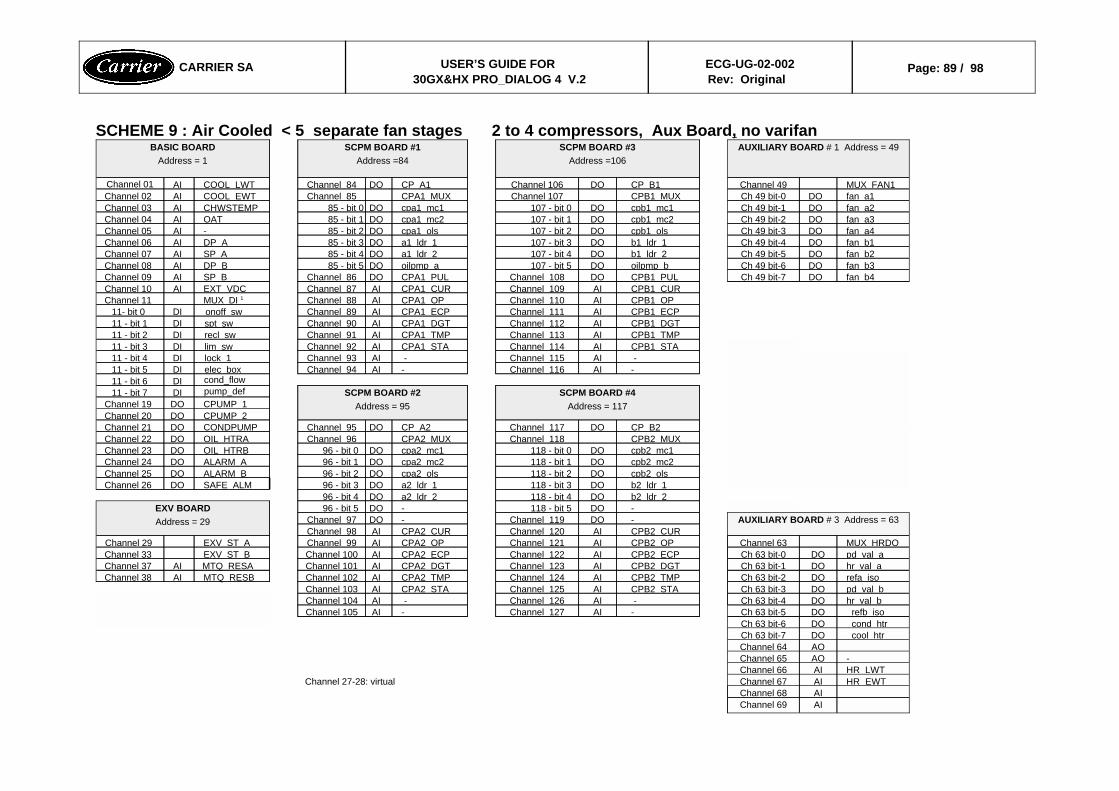
SCHEME 9 : Air Cooled < 5 separate fan stages 2 to 4 compressors, Aux Board, no varifan
AIChannel 69AIChannel 68
HR EWTAIChannel 67Channel 27-28: virtual HR LWTAIChannel 66-AOChannel 65
AOChannel 64cool htrDOCh 63 bit-7cond htrDOCh 63 bit-6refb isoDOCh 63 bit-5-AIChannel 127-AIChannel 105
hr val bDOCh 63 bit-4 -AIChannel 126 -AIChannel 104pd val bDOCh 63 bit-3CPB2 STAAIChannel 125CPA2 STAAIChannel 103refa isoDOCh 63 bit-2CPB2 TMPAIChannel 124CPA2 TMPAIChannel 102MTQ RESBAIChannel 38hr val aDOCh 63 bit-1CPB2 DGTAIChannel 123CPA2 DGTAIChannel 101MTQ RESAAIChannel 37pd val aDOCh 63 bit-0CPB2 ECPAIChannel 122CPA2 ECPAIChannel 100EXV ST BChannel 33MUX HRDOChannel 63CPB2 OPAIChannel 121CPA2 OPAIChannel 99EXV ST AChannel 29
CPB2 CURAIChannel 120CPA2 CURAIChannel 98AUXILIARY BOARD # 3 Address = 63-DOChannel 119-DOChannel 97
-DO118 - bit 5-DO96 - bit 5EXV BOARDAddress = 29
b2 ldr 2DO118 - bit 4a2 ldr 2DO96 - bit 4b2 ldr 1DO118 - bit 3a2 ldr 1DO96 - bit 3SAFE ALMDOChannel 26cpb2 olsDO118 - bit 2cpa2 olsDO96 - bit 2ALARM BDOChannel 25cpb2 mc2DO118 - bit 1cpa2 mc2DO96 - bit 1ALARM ADOChannel 24cpb2 mc1DO118 - bit 0cpa2 mc1DO96 - bit 0OIL HTRBDOChannel 23CPB2 MUXChannel 118CPA2 MUXChannel 96OIL HTRADOChannel 22CP B2DOChannel 117CP A2DOChannel 95CONDPUMPDOChannel 21
CPUMP 2DOChannel 20CPUMP 1DOChannel 19
SCPM BOARD #4Address = 117
SCPM BOARD #2Address = 95
pump_defDI11 - bit 7cond_flowDI11 - bit 6
-AIChannel 116-AIChannel 94elec boxDI11 - bit 5 -AIChannel 115 -AIChannel 93lock 1DI11 - bit 4CPB1 STAAIChannel 114CPA1 STAAIChannel 92lim swDI11 - bit 3CPB1 TMPAIChannel 113CPA1 TMPAIChannel 91recl swDI11 - bit 2CPB1 DGTAIChannel 112CPA1 DGTAIChannel 90spt swDI11 - bit 1CPB1 ECPAIChannel 111CPA1 ECPAIChannel 89onoff swDI11- bit 0CPB1 OPAIChannel 110CPA1 OPAIChannel 88MUX DI 1Channel 11CPB1 CURAIChannel 109CPA1 CURAIChannel 87EXT VDCAIChannel 10
fan b4DOCh 49 bit-7CPB1 PULDOChannel 108CPA1 PULDOChannel 86SP BAIChannel 09fan b3DOCh 49 bit-6oilpmp bDO107 - bit 5oilpmp aDO85 - bit 5DP BAIChannel 08fan b2DOCh 49 bit-5b1 ldr 2DO107 - bit 4a1 ldr 2DO85 - bit 4SP AAIChannel 07fan b1DOCh 49 bit-4b1 ldr 1DO107 - bit 3a1 ldr 1DO85 - bit 3DP AAIChannel 06fan a4DOCh 49 bit-3cpb1 olsDO107 - bit 2cpa1 olsDO85 - bit 2-AIChannel 05fan a3DOCh 49 bit-2cpb1 mc2DO107 - bit 1cpa1 mc2DO85 - bit 1OATAIChannel 04fan a2DOCh 49 bit-1cpb1 mc1DO107 - bit 0cpa1 mc1DO85 - bit 0CHWSTEMPAIChannel 03fan a1DOCh 49 bit-0CPB1 MUXChannel 107CPA1 MUXChannel 85COOL EWTAIChannel 02MUX FAN1Channel 49CP B1DOChannel 106CP A1DOChannel 84COOL LWTAIChannel 01
AUXILIARY BOARD # 1 Address = 49SCPM BOARD #3Address =106
SCPM BOARD #1Address =84
BASIC BOARDAddress = 1
CARRIER SA USER’S GUIDE FOR 30GX&HX PRO_DIALOG 4 V.2
ECG-UG-02-002Rev: Original
Page: 89 / 98
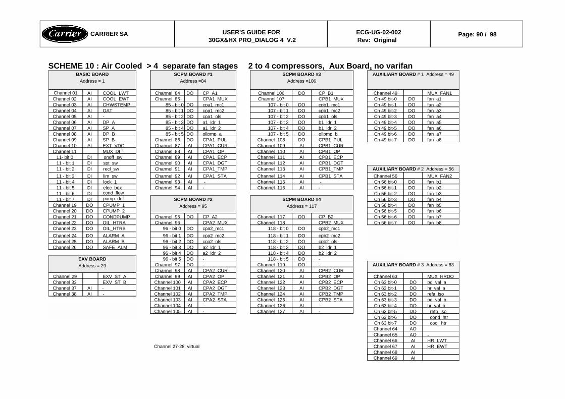
SCHEME 10 : Air Cooled > 4 separate fan stages 2 to 4 compressors, Aux Board, no varifan
AIChannel 69AIChannel 68
HR EWTAIChannel 67Channel 27-28: virtual HR LWTAIChannel 66-AOChannel 65
AOChannel 64cool htrDOCh 63 bit-7cond htrDOCh 63 bit-6refb isoDOCh 63 bit-5-AIChannel 127-AIChannel 105
hr val bDOCh 63 bit-4 -AIChannel 126 -AIChannel 104pd val bDOCh 63 bit-3CPB2 STAAIChannel 125CPA2 STAAIChannel 103refa isoDOCh 63 bit-2CPB2 TMPAIChannel 124CPA2 TMPAIChannel 102-AIChannel 38hr val aDOCh 63 bit-1CPB2 DGTAIChannel 123CPA2 DGTAIChannel 101-AIChannel 37pd val aDOCh 63 bit-0CPB2 ECPAIChannel 122CPA2 ECPAIChannel 100EXV ST BChannel 33MUX HRDOChannel 63CPB2 OPAIChannel 121CPA2 OPAIChannel 99EXV ST AChannel 29
CPB2 CURAIChannel 120CPA2 CURAIChannel 98AUXILIARY BOARD # 3 Address = 63-DOChannel 119-DOChannel 97
-DO118 - bit 5-DO96 - bit 5EXV BOARDAddress = 29
b2 ldr 2DO118 - bit 4a2 ldr 2DO96 - bit 4b2 ldr 1DO118 - bit 3a2 ldr 1DO96 - bit 3SAFE ALMDOChannel 26cpb2 olsDO118 - bit 2cpa2 olsDO96 - bit 2ALARM BDOChannel 25cpb2 mc2DO118 - bit 1cpa2 mc2DO96 - bit 1ALARM ADOChannel 24cpb2_mc1DO118 - bit 0cpa2_mc1DO96 - bit 0OIL_HTRBDOChannel 23
fan b8DOCh 56 bit-7CPB2 MUXChannel 118CPA2 MUXChannel 96OIL HTRADOChannel 22fan b7DOCh 56 bit-6CP B2DOChannel 117CP A2DOChannel 95CONDPUMPDOChannel 21fan b6DOCh 56 bit-5CPUMP 2DOChannel 20fan b5DOCh 56 bit-4CPUMP 1DOChannel 19fan b4DOCh 56 bit-3SCPM BOARD #4
Address = 117SCPM BOARD #2
Address = 95pump_defDI11 - bit 7
fan b3DOCh 56 bit-2cond_flowDI11 - bit 6fan b2DOCh 56 bit-1-AIChannel 116-AIChannel 94elec boxDI11 - bit 5fan b1DOCh 56 bit-0 -AIChannel 115 -AIChannel 93lock 1DI11 - bit 4MUX FAN2Channel 56CPB1 STAAIChannel 114CPA1 STAAIChannel 92lim swDI11 - bit 3
AUXILIARY BOARD # 2 Address = 56CPB1_TMPAIChannel 113CPA1_TMPAIChannel 91recl_swDI11 - bit 2CPB1 DGTAIChannel 112CPA1 DGTAIChannel 90spt swDI11 - bit 1CPB1 ECPAIChannel 111CPA1 ECPAIChannel 89onoff swDI11- bit 0CPB1 OPAIChannel 110CPA1 OPAIChannel 88MUX DI 1Channel 11CPB1 CURAIChannel 109CPA1 CURAIChannel 87EXT VDCAIChannel 10
fan a8DOCh 49 bit-7CPB1 PULDOChannel 108CPA1 PULDOChannel 86SP BAIChannel 09fan a7DOCh 49 bit-6oilpmp bDO107 - bit 5oilpmp aDO85 - bit 5DP BAIChannel 08fan a6DOCh 49 bit-5b1 ldr 2DO107 - bit 4a1 ldr 2DO85 - bit 4SP AAIChannel 07fan a5DOCh 49 bit-4b1 ldr 1DO107 - bit 3a1 ldr 1DO85 - bit 3DP AAIChannel 06fan a4DOCh 49 bit-3cpb1 olsDO107 - bit 2cpa1 olsDO85 - bit 2-AIChannel 05fan a3DOCh 49 bit-2cpb1 mc2DO107 - bit 1cpa1 mc2DO85 - bit 1OATAIChannel 04fan a2DOCh 49 bit-1cpb1 mc1DO107 - bit 0cpa1 mc1DO85 - bit 0CHWSTEMPAIChannel 03fan a1DOCh 49 bit-0CPB1 MUXChannel 107CPA1 MUXChannel 85COOL EWTAIChannel 02MUX FAN1Channel 49CP B1DOChannel 106CP A1DOChannel 84COOL LWTAIChannel 01
AUXILIARY BOARD # 1 Address = 49SCPM BOARD #3Address =106
SCPM BOARD #1Address =84
BASIC BOARDAddress = 1
CARRIER SA USER’S GUIDE FOR 30GX&HX PRO_DIALOG 4 V.2
ECG-UG-02-002Rev: Original
Page: 90 / 98

SCHEME 11: Air Cooled < 5 separate fan stages 2 to 4 compressors Aux Board, varifan
PD_P_BAIChannel 69PD P AAIChannel 68Channel 27-28: virtual HR EWTAIChannel 67HR LWTAIChannel 66-AOChannel 65HR WTRVLAOChannel 64 cool htrDOCh 63 bit-7 cond htrDOCh 63 bit-6refb isoDOCh 63 bit-5-AIChannel 127-AIChannel 105hr val bDOCh 63 bit-4 -AIChannel 126 -AIChannel 104pd val bDOCh 63 bit-3CPB2 STAAIChannel 125CPA2 STAAIChannel 103refa isoDOCh 63 bit-2CPB2 TMPAIChannel 124CPA2 TMPAIChannel 102MTQ RESBAIChannel 38hr val aDOCh 63 bit-1CPB2 DGTAIChannel 123CPA2 DGTAIChannel 101MTQ RESA-AIChannel 37pd val aDOCh 63 bit-0CPB2 ECPAIChannel 122CPA2 ECPAIChannel 100EXV ST B Channel 33MUX HRDOChannel 63CPB2 OPAIChannel 121CPA2 OPAIChannel 99EXV ST B Channel 29
CPB2 CURAIChannel 120CPA2 CURAIChannel 98AUXILIARY BOARD # 3 Address = 63-DOChannel 119-DOChannel 97EXV BOARD Address = 29
-DO118 - bit 5-DO96 - bit 5b2 ldr 2DO118 - bit 4a2 ldr 2DO96 - bit 4SAFE ALMDOChannel 26b2 ldr 1DO118 - bit 3a2 ldr 1DO96 - bit 3ALARM BDOChannel 25cpb2 olsDO118 - bit 2cpa2 olsDO96 - bit 2ALARM ADOChannel 24cpb2 mc2DO118 - bit 1cpa2 mc2DO96 - bit 1OIL HTRBDOChannel 23cpb2 mc1DO118 - bit 0cpa2 mc1DO96 - bit 0OIL HTRADOChannel 22CPB2 MUXChannel 118CPA2 MUXChannel 96CONDPUMPDOChannel 21CP B2DOChannel 117CP A2DOChannel 95CPUMP 2DOChannel 20
CPUMP 1DOChannel 19SCPM BOARD #4 Address = 117SCPM BOARD #2 Address = 95pump_defDI11 - bit 7
cond_flowDI11 - bit 6-AIChannel 116-AIChannel 94elec boxDI11 - bit 5 -AIChannel 115 -AIChannel 93lock 1DI11 - bit 4CPB1 STAAIChannel 114CPA1 STAAIChannel 92lim swDI11 - bit 3CPB1 TMPAIChannel 113CPA1 TMPAIChannel 91recl swDI11 - bit 2CPB1 DGTAIChannel 112CPA1 DGTAIChannel 90spt swDI11 - bit 1
-AIChan 52-54CPB1 ECPAIChannel 111CPA1 ECPAIChannel 89onoff swDI11- bit 0HD BAOChannel 51CPB1 OPAIChannel 110CPA1 OPAIChannel 88MUX DI 1Channel 11HD AAOChannel 50CPB1 CURAIChannel 109CPA1 CURAIChannel 87EXT VDCAIChannel 10fan b3DOCh 49 bit-7CPB1 PULDOChannel 108CPA1 PULDOChannel 86SP BAIChannel 09fan b2DOCh 49 bit-6oilpmp bDO107 - bit 5oilpmp aDO85 - bit 5DP BAIChannel 08fan b1DOCh 49 bit-5b1 ldr 2DO107 - bit 4a1 ldr 2DO85 - bit 4SP AAIChannel 07-DOCh 49 bit-4b1 ldr 1DO107 - bit 3a1 ldr 1DO85 - bit 3DP AAIChannel 06fan a3DOCh 49 bit-3cpb1 olsDO107 - bit 2cpa1 olsDO85 - bit 2-AIChannel 05fan a2DOCh 49 bit-2cpb1 mc2DO107 - bit 1cpa1 mc2DO85 - bit 1OATAIChannel 04fan a1DOCh 49 bit-1cpb1 mc1DO107 - bit 0cpa1 mc1DO85 - bit 0CHWSTEMPAIChannel 03-DOCh 49 bit-0CPB1 MUXChannel 107CPA1 MUXChannel 85COOL EWTAIChannel 02MUX FAN1Channel 49CP B1DOChannel 106CP A1DOChannel 84COOL LWTAIChannel 01
AUXILIARY BOARD # 1 Address = 49SCPM BOARD #3 Address =106SCPM BOARD #1 Address =84BASIC BOARDAddress = 1
CARRIER SA USER’S GUIDE FOR 30GX&HX PRO_DIALOG 4 V.2
ECG-UG-02-002Rev: Original
Page: 91 / 98

SCHEME 12 : Air Cooled > 4 separate fan stages 2 to 4 Compressors Aux Board, varifan
PD_P_BAIChannel 69PD P AAIChannel 68Channel 27-28: virtual HR EWTAIChannel 67HR LWTAIChannel 66-AOChannel 65HR WTRVLAOChannel 64 cool htrDOCh 63 bit-7 cond htrDOCh 63 bit-6refb isoDOCh 63 bit-5-AIChannel 127-AIChannel 105hr val bDOCh 63 bit-4 -AIChannel 126 -AIChannel 104pd val bDOCh 63 bit-3CPB2 STAAIChannel 125CPA2 STAAIChannel 103refa isoDOCh 63 bit-2CPB2 TMPAIChannel 124CPA2 TMPAIChannel 102MTQ RESBAIChannel 38hr val aDOCh 63 bit-1CPB2 DGTAIChannel 123CPA2 DGTAIChannel 101MTQ RESAAIChannel 37pd val aDOCh 63 bit-0CPB2 ECPAIChannel 122CPA2 ECPAIChannel 100EXV ST B Channel 33MUX HRDOChannel 63CPB2 OPAIChannel 121CPA2 OPAIChannel 99EXV ST B Channel 29
CPB2 CURAIChannel 120CPA2 CURAIChannel 98AUXILIARY BOARD # 3 Address = 63-DOChannel 119-DOChannel 97EXV BOARD#1 Address = 29
-DO118 - bit 5-DO96 - bit 5-AIChan 59-62b2 ldr 2DO118 - bit 4a2 ldr 2DO96 - bit 4SAFE ALMDOChannel 26
AOChannel 58b2 ldr 1DO118 - bit 3a2 ldr 1DO96 - bit 3ALARM BDOChannel 25HD BAOChannel 57cpb2 olsDO118 - bit 2cpa2 olsDO96 - bit 2ALARM ADOChannel 24fan b7DOCh 56 bit-7cpb2 mc2DO118 - bit 1cpa2 mc2DO96 - bit 1OIL HTRBDOChannel 23fan b6DOCh 56 bit-6cpb2 mc1DO118 - bit 0cpa2 mc1DO96 - bit 0OIL HTRADOChannel 22fan b5DOCh 56 bit-5CPB2 MUXChannel 118CPA2 MUXChannel 96CONDPUMPDOChannel 21fan b4DOCh 56 bit-4CP B2DOChannel 117CP A2DOChannel 95CPUMP 2DOChannel 20fan b3DOCh 56 bit-3CPUMP 1DOChannel 19fan b2DOCh 56 bit-2SCPM BOARD #4 Address = 117SCPM BOARD #2 Address = 95pump_defDI11 - bit 7fan b1DOCh 56 bit-1cond_flowDI11 - bit 6-DOCh 56 bit-0-AIChannel 116-AIChannel 94elec boxDI11 - bit 5MUX FAN1Channel 56 -AIChannel 115 -AIChannel 93lock 1DI11 - bit 4
CPB1 STAAIChannel 114CPA1 STAAIChannel 92lim swDI11 - bit 3AUXILIARY BOARD # 2 Address = 56CPB1 TMPAIChannel 113CPA1 TMPAIChannel 91recl swDI11 - bit 2
CPB1 DGTAIChannel 112CPA1 DGTAIChannel 90spt swDI11 - bit 1-AIChan 52-54CPB1 ECPAIChannel 111CPA1 ECPAIChannel 89onoff swDI11- bit 0
AOChannel 51CPB1 OPAIChannel 110CPA1 OPAIChannel 88MUX DI 1Channel 11HD AAOChannel 50CPB1 CURAIChannel 109CPA1 CURAIChannel 87EXT VDCAIChannel 10fan a7DOCh 49 bit-7CPB1 PULDOChannel 108CPA1 PULDOChannel 86SP BAIChannel 09fan a6DOCh 49 bit-6oilpmp bDO107 - bit 5oilpmp aDO85 - bit 5DP BAIChannel 08fan a5DOCh 49 bit-5b1 ldr 2DO107 - bit 4a1 ldr 2DO85 - bit 4SP AAIChannel 07fan a4DOCh 49 bit-4b1 ldr 1DO107 - bit 3a1 ldr 1DO85 - bit 3DP AAIChannel 06fan a3DOCh 49 bit-3cpb1 olsDO107 - bit 2cpa1 olsDO85 - bit 2-AIChannel 05fan a2DOCh 49 bit-2cpb1 mc2DO107 - bit 1cpa1 mc2DO85 - bit 1OATAIChannel 04fan a1DOCh 49 bit-1cpb1 mc1DO107 - bit 0cpa1 mc1DO85 - bit 0CHWSTEMPAIChannel 03f-DOCh 49 bit-0CPB1 MUXChannel 107CPA1 MUXChannel 85COOL EWTAIChannel 02MUX FAN1Channel 49CP B1DOChannel 106CP A1DOChannel 84COOL LWTAIChannel 01
AUXILIARY BOARD # 1 Address = 49SCPM BOARD #3 Address =106SCPM BOARD #1 Address =84BASIC BOARDAddress = 1
CARRIER SA USER’S GUIDE FOR 30GX&HX PRO_DIALOG 4 V.2
ECG-UG-02-002Rev: Original
Page: 92 / 98

SCHEME 13 : Air Cooled Chillers >2 separate fan stages, 2 to 4 Compressors, Cooler heater = NO, Reclaim option = no, No Aux Board
fan b443 - bit 3Channel 80 - 83 : freeHD BAOChannel 52fan b343 - bit 2Channel 27-28: virtual HD AAOChannel 51fan b243 - bit 1Channel 26 : DO unusedHR EWTAIChannel 50fan b143 - bit 0HR LWTAIChannel 49
MUX FAN2Channel 43AIChannel 48AIChannel 47
4xDO BOARD #2Address = 43
-AIChannel 127-AIChannel 105 -AIChannel 126 -AIChannel 1044xAI - 2xAO BOARD
Address = 47
fan a439 - bit 3CPB2 STAAIChannel 125CPA2 STAAIChannel 103fan a339 - bit 2CPB2 TMPAIChannel 124CPA2 TMPAIChannel 102MTQ RESBAIChannel 38fan a239 - bit 1CPB2 DGTAIChannel 123CPA2 DGTAIChannel 101MTQ RESAAIChannel 37fan a139 - bit 0CPB2 ECPAIChannel 122CPA2 ECPAIChannel 100EXV ST BChannel 33
MUX FAN1Channel 39CPB2 OPAIChannel 121CPA2 OPAIChannel 99EXV ST AChannel 29CPB2 CURAIChannel 120CPA2 CURAIChannel 98-DOChannel 119-DOChannel 97
4xDO BOARD #1Address = 39
-DO118 - bit 5-DO96 - bit 5EXV BOARDAddress = 29
b2 ldr 2DO118 - bit 4a2 ldr 2DO96 - bit 4b2 ldr 1DO118 - bit 3a2 ldr 1DO96 - bit 3unusedDOCh 26-28cpb2 olsDO118 - bit 2cpa2 olsDO96 - bit 2ALARM BDOChannel 25cpb2 mc2DO118 - bit 1cpa2 mc2DO96 - bit 1ALARM ADOChannel 24cpb2 mc1DO118 - bit 0cpa2 mc1DO96 - bit 0OIL HTRBDOChannel 23CPB2 MUXChannel 118CPA2 MUXChannel 96OIL HTRADOChannel 22CP B2DOChannel 117CP A2DOChannel 95DOChannel 21
CPUMP 2DOChannel 20CPUMP 1DOChannel 19
SCPM BOARD #4Address = 117
SCPM BOARD #2Address = 95
pump_defDI11 - bit 7cond_flowDI11 - bit 6
-AIChannel 116-AIChannel 94elec boxDI11 - bit 5 -AIChannel 115 -AIChannel 93lock 1DI11 - bit 4CPB1 STAAIChannel 114CPA1 STAAIChannel 92lim swDI11 - bit 3CPB1 TMPAIChannel 113CPA1 TMPAIChannel 91recl swDI11 - bit 2CPB1 DGTAIChannel 112CPA1 DGTAIChannel 90spt swDI11 - bit 1CPB1 ECPAIChannel 111CPA1 ECPAIChannel 89onoff swDI11- bit 0CPB1 OPAIChannel 110CPA1 OPAIChannel 88MUX DI 1Channel 11CPB1 CURAIChannel 109CPA1 CURAIChannel 87EXT VDCAIChannel 10CPB1 PULDOChannel 108CPA1 PULDOChannel 86SP BAIChannel 09oilpmp bDO107 - bit 5oilpmp aDO85 - bit 5DP BAIChannel 08b1 ldr 2DO107 - bit 4a1 ldr 2DO85 - bit 4SP AAIChannel 07b1 ldr 1DO107 - bit 3a1 ldr 1DO85 - bit 3DP AAIChannel 06cpb1 olsDO107 - bit 2cpa1 olsDO85 - bit 2-AIChannel 05cpb1 mc2DO107 - bit 1cpa1 mc2DO85 - bit 1OATAIChannel 04cpb1 mc1DO107 - bit 0cpa1 mc1DO85 - bit 0CHWSTEMPAIChannel 03CPB1 MUXChannel 107CPA1 MUXChannel 85COOL EWTAIChannel 02CP B1DOChannel 106CP A1DOChannel 84COOL LWTAIChannel 01
SCPM BOARD #3Address =106
SCPM BOARD #1Address =84
BASIC BOARDAddress = 1
CARRIER SA USER’S GUIDE FOR 30GX&HX PRO_DIALOG 4 V.2
ECG-UG-02-002Rev: Original
Page: 93 / 98

SCHEME 14 : Air Cooled Chillers < 3 separate fan stages 2 to 4 Compressors, Cooler heater = YES or Reclaim option= YES, No Aux Board
Channel 80 - 83 : freeHD BAOChannel 52Channel 27-28: virtual HD AAOChannel 51Channel 26 : DO unused-AIChannel 50
-AIChannel 49AIChannel 48AIChannel 47
-AIChannel 127-AIChannel 105 -AIChannel 126 -AIChannel 1044xAI - 2xAO BOARD
Address = 47
fan b239 - bit 3CPB2 STAAIChannel 125CPA2 STAAIChannel 103fan b139 - bit 2CPB2 TMPAIChannel 124CPA2 TMPAIChannel 102MTQ RESBAIChannel 38fan a239 - bit 1CPB2 DGTAIChannel 123CPA2 DGTAIChannel 101MTQ RESAAIChannel 37fan a139 - bit 0CPB2 ECPAIChannel 122CPA2 ECPAIChannel 100EXV ST BChannel 33
MUX FAN1Channel 39CPB2 OPAIChannel 121CPA2 OPAIChannel 99EXV ST AChannel 29CPB2 CURAIChannel 120CPA2 CURAIChannel 98-DOChannel 119-DOChannel 97
4xDO BOARD #1Address = 39
-DO118 - bit 5-DO96 - bit 5EXV BOARDAddress = 29
b2 ldr 2DO118 - bit 4a2 ldr 2DO96 - bit 4virtual-unusedDOCh 78- 79b2 ldr 1DO118 - bit 3a2 ldr 1DO96 - bit 3unusedDOCh 26-28refb isoDO 68 bit 9cpb2 olsDO118 - bit 2cpa2 olsDO96 - bit 2ALARM BDOChannel 25refa isoDO 68 bit 8cpb2 mc2DO118 - bit 1cpa2 mc2DO96 - bit 1ALARM ADOChannel 24cool htrDO 68 bit 7cpb2 mc1DO118 - bit 0cpa2 mc1DO96 - bit 0OIL HTRBDOChannel 23-DO 68 bit 6CPB2 MUXChannel 118CPA2 MUXChannel 96OIL HTRADOChannel 22pd val bDO 68 bit 5CP B2DOChannel 117CP A2DOChannel 95HPUMPDOChannel 21pd val aDO 68 bit 4CPUMP 2DOChannel 20cond htrDO 68 bit 3CPUMP 1DOChannel 19-DO 68 bit 2SCPM BOARD #4
Address = 117SCPM BOARD #2
Address = 95pump_defDI11 - bit 7
hr val bDO 68 bit 1cond_flowDI11 - bit 6hr val aDO 68 bit 0-AIChannel 116-AIChannel 94elec boxDI11 - bit 5MUX NRCPMUXChannel 68 -AIChannel 115 -AIChannel 93lock 1DI11 - bit 4-DIChannel 67CPB1 STAAIChannel 114CPA1 STAAIChannel 92lim swDI11 - bit 3-DIChannel 66CPB1 TMPAIChannel 113CPA1 TMPAIChannel 91recl swDI11 - bit 2-DIChannel 65CPB1 DGTAIChannel 112CPA1 DGTAIChannel 90spt swDI11 - bit 1-DIChannel 64CPB1 ECPAIChannel 111CPA1 ECPAIChannel 89onoff swDI11- bit 0-DIChannel 63CPB1 OPAIChannel 110CPA1 OPAIChannel 88MUX DI 1Channel 11-DIChannel 62CPB1 CURAIChannel 109CPA1 CURAIChannel 87EXT VDCAIChannel 10-DIChannel 61CPB1 PULDOChannel 108CPA1 PULDOChannel 86SP BAIChannel 09-DIChannel 60oilpmp bDO107 - bit 5oilpmp aDO85 - bit 5DP BAIChannel 08HR WTRVLAOChannel 59b1 ldr 2DO107 - bit 4a1 ldr 2DO85 - bit 4SP AAIChannel 07PD P BAIChannel 58b1 ldr 1DO107 - bit 3a1 ldr 1DO85 - bit 3DP AAIChannel 06PD P AAIChannel 57cpb1 olsDO107 - bit 2cpa1 olsDO85 - bit 2-AIChannel 05-AIChannel 56cpb1 mc2DO107 - bit 1cpa1 mc2DO85 - bit 1OATAIChannel 04-AIChannel 55cpb1 mc1DO107 - bit 0cpa1 mc1DO85 - bit 0CHWSTEMPAIChannel 03HR EWTAIChannel 54CPB1 MUXChannel 107CPA1 MUXChannel 85COOL EWTAIChannel 02HR LWTAIChannel 53CP B1DOChannel 106CP A1DOChannel 84COOL LWTAIChannel 01
NRCP BASIC BOARDAddress = 53
SCPM BOARD #3Address =106
SCPM BOARD #1Address =84
BASIC BOARDAddress = 1
CARRIER SA USER’S GUIDE FOR 30GX&HX PRO_DIALOG 4 V.2
ECG-UG-02-002Rev: Original
Page: 94 / 98

SCHEME 15 : Air Cooled Chillers > 2 separate fan stages 2 to 4 Compressors, Cooler heater = YES or Reclaim option= YES, No Aux Board
fan b443 - bit 3Channel 80 - 83 : freeHD BAOChannel 52fan b343 - bit 2Channel 27-28: virtual HD AAOChannel 51fan b243 - bit 1Channel 26 : DO unused-AIChannel 50fan b143 - bit 0-AIChannel 49
MUX FAN2Channel 43AIChannel 48AIChannel 47
4xDO BOARD #2Address = 43
-AIChannel 127-AIChannel 105 -AIChannel 126 -AIChannel 1044xAI - 2xAO BOARD
Address = 47
fan a439 - bit 3CPB2 STAAIChannel 125CPA2 STAAIChannel 103fan a339 - bit 2CPB2 TMPAIChannel 124CPA2 TMPAIChannel 102MTQ RESBAIChannel 38fan a239 - bit 1CPB2 DGTAIChannel 123CPA2 DGTAIChannel 101MTQ RESAAIChannel 37fan a139 - bit 0CPB2 ECPAIChannel 122CPA2 ECPAIChannel 100EXV ST BChannel 33
MUX FAN1Channel 39CPB2 OPAIChannel 121CPA2 OPAIChannel 99EXV ST AChannel 29CPB2 CURAIChannel 120CPA2 CURAIChannel 98-DOChannel 119-DOChannel 97
4xDO BOARD #1Address = 39
-DO118 - bit 5-DO96 - bit 5EXV BOARDAddress = 29
b2 ldr 2DO118 - bit 4a2 ldr 2DO96 - bit 4virtual-unusedDOCh 78- 79b2 ldr 1DO118 - bit 3a2 ldr 1DO96 - bit 3unusedDOCh 26-28refb isoDO 68 bit 9cpb2 olsDO118 - bit 2cpa2 olsDO96 - bit 2ALARM BDOChannel 25refa isoDO 68 bit 8cpb2 mc2DO118 - bit 1cpa2 mc2DO96 - bit 1ALARM ADOChannel 24cool htrDO 68 bit 7cpb2 mc1DO118 - bit 0cpa2 mc1DO96 - bit 0OIL HTRBDOChannel 23-DO 68 bit 6CPB2 MUXChannel 118CPA2 MUXChannel 96OIL HTRADOChannel 22pd val bDO 68 bit 5CP B2DOChannel 117CP A2DOChannel 95CONDPUMPDOChannel 21pd val aDO 68 bit 4CPUMP 2DOChannel 20cond htrDO 68 bit 3CPUMP 1DOChannel 19-DO 68 bit 2SCPM BOARD #4
Address = 117SCPM BOARD #2
Address = 95pump_defDI11 - bit 7
hr val bDO 68 bit 1cond_flowDI11 - bit 6hr val aDO 68 bit 0-AIChannel 116-AIChannel 94elec boxDI11 - bit 5MUX NRCPMUXChannel 68 -AIChannel 115 -AIChannel 93lock 1DI11 - bit 4-DIChannel 67CPB1 STAAIChannel 114CPA1 STAAIChannel 92lim swDI11 - bit 3-DIChannel 66CPB1 TMPAIChannel 113CPA1 TMPAIChannel 91recl swDI11 - bit 2-DIChannel 65CPB1 DGTAIChannel 112CPA1 DGTAIChannel 90spt swDI11 - bit 1-DIChannel 64CPB1 ECPAIChannel 111CPA1 ECPAIChannel 89onoff swDI11- bit 0-DIChannel 63CPB1 OPAIChannel 110CPA1 OPAIChannel 88MUX DI 1Channel 11-DIChannel 62CPB1 CURAIChannel 109CPA1 CURAIChannel 87EXT VDCAIChannel 10-DIChannel 61CPB1 PULDOChannel 108CPA1 PULDOChannel 86SP BAIChannel 09-DIChannel 60oilpmp bDO107 - bit 5oilpmp aDO85 - bit 5DP BAIChannel 08HR WTRVLAOChannel 59b1 ldr 2DO107 - bit 4a1 ldr 2DO85 - bit 4SP AAIChannel 07PD P BAIChannel 58b1 ldr 1DO107 - bit 3a1 ldr 1DO85 - bit 3DP AAIChannel 06PD P AAIChannel 57cpb1 olsDO107 - bit 2cpa1 olsDO85 - bit 2-AIChannel 05-AIChannel 56cpb1 mc2DO107 - bit 1cpa1 mc2DO85 - bit 1OATAIChannel 04-AIChannel 55cpb1 mc1DO107 - bit 0cpa1 mc1DO85 - bit 0CHWSTEMPAIChannel 03HR EWTAIChannel 54CPB1 MUXChannel 107CPA1 MUXChannel 85COOL EWTAIChannel 02HR LWTAIChannel 53CP B1DOChannel 106CP A1DOChannel 84COOL LWTAIChannel 01
NRCP BASIC BOARDAddress = 53
SCPM BOARD #3Address =106
SCPM BOARD #1Address =84
BASIC BOARDAddress = 1
CARRIER SA USER’S GUIDE FOR 30GX&HX PRO_DIALOG 4 V.2
ECG-UG-02-002Rev: Original
Page: 95 / 98

CARRIER SA USER’S GUIDE FOR 30GX&HX PRO_DIALOG 4 V.2
ECG-UG-02-002Rev: Original
Page: 96 / 98

Default = 0, no parity and 1 stop bitXJBUS parity and stop bitR/W114 [72h]Default = 1XJBUS addressR/W113 [71h]Default = 9600XJBUS baud rateR/W112 [70h]
XDemand Limit ValueR/W109 [h6D]Write value must be multiplied by 10XControl PointR/W108 [h6C]0 = Off 1 = OnXChiller Start/Stop ***R/W107 [6Bh]Write value must be multiplied by 10XHeating Setpoint R/W99 [h62]Write value must be multiplied by 10XCooling Setpoint 2R/W98 [h62]Write value must be multiplied by 10XCooling Setpoint 1R/W97 [h61]
XJBUS alarm codeR66 [h42]2 = CCN communication failureXGateway current alarm codeR61 [h3D]
XActive alarm 5*R45 [h2D]XActive alarm 4*R44 [h2C]XActive alarm 3*R43 [h2B]XActive alarm 2*R42 [h2A]
Provide the code of up to 5 active alarms. Theseare stored in arrival order.Alarms read from CCN/JBUS are alarm index butnot alarms codes as followsfrom iom, alarm codes 101 to 117 , index = 88(code 101) to 104 ( code 117)from iom, alarm codes 201 to 217 , index = 105(code 201) to 121 (code 217)- - - - - - - -from iom, alarm codes 401 to 417 , index = 139(code 401) to 155 (code 417)
XActive alarm 1*R41 [h29]XTotal Number of active alarmsR40 [h28]XR---XCompressor B2 HoursR16 [h10]XCompressor B1 HoursR15 [h0F]XCompressor A2 HoursR14 [h0E]XCompressor A1 HoursR13 [h0D]XMachine Operating HoursR12 [h0C]XCondenser Pump statusR11 [h0B]XCooler Pump # 1 statusR10 [h0A]
0 = cool, 1 = heatXHeat Cool SelectR9 [h09]0 = Normal, 16 = Partial, 25 = ShutdownXAlarm StateR8 [h08]0 = Off, 1 = On, 6=delay, 24=runningXChiller StateR7 [h07]
XDemand Limit R6 [h06]XUnit Percent Active CapacityR5 [h05]
Read value must be divided by 10XControl PointR4 [h04]Read value must be divided by 10XCircuit B Discharge PressureR3 [h03]Read value must be divided by 10XCircuit A Discharge PressureR2 [h02]Read value must be divided by 10XLeaving Fluid TemperatureR1 [h01]Read value must be divided by 10XEntering Fluid TemperatureR0 [h00]
FLOATINTREMARK**TYPE**CONTENTJBUS
ACCESSREGISTERADDRESS
APPENDIX E- JBUS MEMORY MAPPING - 30GX&HX V2.X DEFAULT CONFIGURATION
CARRIER SA USER’S GUIDE FOR30GX&HX PRO_DIALOG 4 V.2
ECG-UG-02-002Rev : Original Page: 96 / 98

COMFORTNETWORK
CARRIER SAUSER'S GUIDE FOR
30GX&HX PRO_DIALOG 4 V.2ECG-UG-02-002
Rev: OriginalPage:97 / 98
© CARRIER S.ANOT TO BE DISCLOSED TO PERSONS OUTSIDE CARRIER ORGANIZATION
PRO-DIALOG 30DQ
PRO-DIALOG 30GX & HX
REPEATER
REPEATER
CCN/JBUS
DATAPORT I
DATAPORT II
PRO-DIALOG 30GH
FLOTRONIC II
FLOTRONIC I
FSM
FLOTRONIC I
3200 MP
19XL
AUTODIAL
AUTODIAL
GATEWAY
GATEWAY
MODEM
MODEM
BUILDING
BUILDING
SUPERVISOR
SUPERVISOR
NETWORKSERVICETOOL
PRIMARY CCN BUS
GW
WSM
39 L
CSM
GW
GW
TSM
39 L
39 L
DATA COLLECTION
NDS BRIDGE
DATA TRANSFERT
TSM SECONDARY BUS
SECONDARYBUS
AIR TERMINAL
AIR TERMINAL
35
37
GATEWAYJ-BUS/RS-485 TO
TO
TO
BMS
BMS
BMS
LOCAL BUILDING SUPERVISOR
REMOTE BUILDING SUPERVISOR
SAM
RS-485
ASCII/RS-232
ASCII/RS-232
SERVICE WINDOW 2

APPENDIX F SAM SCREEN FOR 30GX&HX PRO-DIALOG PLUS
CARRIER SAUSER'S GUIDE FOR
30GX&HX PRO_DIALOG 4 V.2ECG-UG-02-002
Rev: OriginalPage:98 / 98
© CARRIER S.ANOT TO BE DISCLOSED TO PERSONS OUTSIDE CARRIER ORGANIZATION
!ON - COOLING 05-20-94 15:00NORMAL 255 hours
ENTERING LEAVING OUTDOOR
12.5 6.7 12CAPACITY HEATCOOL PUMP
50 0 0CTRL PNT CTRL WT LIMIT
6.0 6.7 100 CCN LOCAL REMOTE MENU LOCAL
CARRIER CONFORTNETWORK
OFFOFF - COOLER HEATER ACTIVEREADY TO START IN XX MINON - COOLINGON - COOL-RECLAIMON - COOL-RESET ACTIVEON - COOL- RECL-RESETON - HEATINGON - HEAT - RESET ACTIVEON - MASTER AND LEAD UNITON - MASTER AND LAG UNITON - SLAVE AND LEAD UNITON - SLAVE AND LAG UNITON - UNDER SM CONTROL
NORMALPARTIAL: ALARM XXSHUTDOWN: ALARM XX