User’s Guide - Puget Sound Instrument · 7.7 Automatic Compass Deviation Correction ... 43 7.8...
37
User’s Guide for Leisure Pilots 715, 730 & 740 Issue 06 for use with version V3.00 software (or later) in the Pilot Computer
Transcript of User’s Guide - Puget Sound Instrument · 7.7 Automatic Compass Deviation Correction ... 43 7.8...

User’s Guidefor
Leisure Pilots715, 730 & 740
Issue 06for use with
version V3.00 software (or later) in the Pilot Computer

Leisure Pilots 715, 730 and 740
32
WWWWWelcome elcome elcome elcome elcome ....All of us at would like to welcome you to the reliableworld of our autopilot systems and thank you for buying ourproduct.
Your new autopilot, whether it is the fixed 730 or 740 or thehand held 715, is easy to operate, helping you to enjoy yourboating. It will consistently steer your boat on a straightcourse, helping to give optimum fuel economy and minimisewear on your steering system.
Your Safety It is the responsibility of the Helmsman to ensure andmaintain the safe navigation and control of thevessel at all times. The autopilot is only an aid tosteering, suitable for unconfined waters.
Your System The system consists of the following basic units:
• Autopilot Control• Pilot Computer• Compass Sensor• Rudder Feedback Unit• Drive Unit for the steering system
It may also include options such as:• a second autopilot control• connections to a chartplotter or navigator• connections to instruments
These options can be added to the system at any time. YourCetrekCetrekCetrekCetrekCetrek Dealer will be glad to give you the latest informationon any of them.
DocumentReference:
807300Issue 06
March 1999
EMC Directive 89/336/EEC
This product has been designed to be compliant with the above Directive.Maximum performance and compliance with the EMC Directive can only be
ensured by correct installation. It is strongly recommended that theinstallation conforms with the following standards:
SMALL CRAFT - ELECTRICAL SYSTEMS:a) ISO 10133 - Extra Low-Voltage DC Installationsb) ISO 13297 - Alternating Current InstallationsISO - International Standards Organisation
The information contained in this manual is believed to be accurate at thetime of going to print but no responsibility, direct or consequential, can be
accepted by Cetrek Ltd for damage resulting from the use of thisinformation. Cetrek Ltd reserve the right to make changes without notice toany of its products, documentation or services. © Cetrek Ltd 1997

Leisure Pilots 715, 730 and 740
54
Contents
1. Using the Pilot ..................................................71.1 The Autopilot Control .................................... 71.2 The LCD display .............................................. 91.3 The Function Keys .......................................... 91.4 Getting started............................................. 101.5 Standby mode (Manual steering) ................. 111.6 Jog Steer ...................................................... 111.7 Auto mode (with“COMPASS” control ) ....... 111.8 Selecting how the Arrow Keys function ....... 12
Dodge .......................................................... 12Changing course .......................................... 13Tack .............................................................. 13
1.9 The Information display ............................... 131.10 Rudder Position Indicator ............................. 151.11 Digital Rudder position display ..................... 161.12 Lighting ........................................................ 161.13 Pilot A, B, C (619 only) .................................. 16
2. Compass course control .................................17To engage Compass course control ............. 17Tacking under Compass control ................... 17
3. Wind course control .......................................18To engage Wind course control ................... 18Tacking under Wind control ......................... 18
4. Navigator course control ................................204.1 NMEA 0183 messages ................................. 214.2 Using Navigator control ............................... 224.3 Selecting a Navigator ................................... 224.4 To engage Navigator control ........................ 224.5 Navigator errors ........................................... 24
5. Sea State Adjustments ...................................255.1 Rudder ratio ................................................. 255.2 Response (also known as Yaw). ................... 25
Adaptive control .......................................... 26Manual control ............................................ 26
6. Installing the Pilot ..........................................316.1 Specifications ............................................... 316.2 Mounting the Autopilot Control .................. 326.3 Connecting the Pilot Control ....................... 35
7. Dockside and Sea trial settings......................36Using the settings menus............................. 36
Dockside Settings ...........................................377.1 Powering up for the first time...................... 377.2 Setting the Rudder Feedback type. .............. 377.3 Setting the Boat Type. .................................. 387.4 Rudder settings routine ............................... 397.5 Align Compass ............................................. 407.6 Checking the settings .................................. 41Sea Trials .........................................................437.7 Automatic Compass Deviation Correction ... 437.8 Compass alignment (Cetrek compass’) ........ 457.9 Center Rudder .............................................. 467.10 Final Sea Trial and Fine Tuning ..................... 46
8. Pilot configuration reference .........................488.30 Pilot Configuration menu summary ............. 63
9. System Messages............................................6410. System Faults ..................................................6511. Rudder Angle Template ..................................6712. Default settings ..............................................68
Index ...................................................................... 69

Leisure Pilots 715, 730 and 740
76
1.1.1.1.1. Using the PilotUsing the PilotUsing the PilotUsing the PilotUsing the Pilot
1.1 The Autopilot Control
The Pilot Control is where the helmsman controls all of thefunctions of the autopilot system. Operation has been keptvery simple with just 5 or 6 function keys and a CourseControl Knob.
The LCD constantly displays autopilot related data; Autopilotstatus, Heading or Course, Rudder Position and Coursecontrol device.
It also has an information display area across the top of theLCD. You can choose which of the available information isshown here, giving you quick access to relevant information.You can also quickly access and change Sea State settings.
Course changing is a simple turn of the Course control knobor a press of the direction key.
The direction keys can be either used for Course change orDodge. Course change can be either 1º per press or 10º perpress. Dodge is an easy means of momentarily changingcourse to avoid an obstruction, release the key and the pilotreturns you back to your original course.
The stylish Pilot 715 has been designed for hand heldcontrol.
The compact Pilot 730 and the larger 740 have beendesigned for bulkhead or trunnion mounting.
The only operating difference between the three pilots is thatthe 715 does not have a dedicated ‘OFF’ function key.
In an EMERGENCY press the key or press and
hold the key for three seconds to turn theautopilot OFF and regain manual control.
715 PilotControl
Liquid CrystalDisplay
Function keys
Observe 715socket and plug
mating alignment
Course controlknob
730 Pilot Control
740 Pilot Control

Leisure Pilots 715, 730 and 740
98
1.2 The LCD display
The LCD Display
1.3 The Function Keys• powers up (turns on) the autopilot system.• with the system powered up, toggles between Standby
and Auto mode.• press and hold for three seconds to switch the system OFF
and save any changed settings.• Accepts new course in Manual waypoint sequence.
• gives access to lighting and selected Sea stateadjustments, plus NMEA information.
• press and hold for three seconds to access the full list ofinformation that may be viewed.
• selects the course control device; Compass, Wind orNavigator.
• press and hold for three seconds to display the PilotConfiguration Menu.
• press and hold the and keys together for threeseconds to access the Dockside and Sea Trial Menus.
• to Dodge, Change course or Tack in Auto mode,depending on function selected.
• moves the rudder in Standby mode.• changes the values of the settings.
Course Control knob• to change course in Auto mode.• changes value in some menus.
fitted on the Pilot 730 and 740.• saves the settings and powers down (turns off) the system
(the Auto key still turns the system off as well).
Autopilot status symbols
Information display
Course controlindicators
Alarm symbol
Heading andCourse display
Rudder positionindicator
Steering motoractivity indicators
Functionality of the Pilot system is dependant on the PilotComputer fitted. The basic unit is the 930609, the enhancedunit is the 930619.
This User’s Guide covers both systems. Parts that are relevantonly to the 619 are marked as such.
A summary of the extra features a 619 systems has:
• 3 memory settings, PILOT A, B & C.
• up to 3 navigators can be connected and easily selected.
• a Gyro compass can be used.
• an Off Course alarm is available.
• a ‘Turn Rate’ setting is available.
• an external alarm connection is available.
• a Rate sensor connection is available.
Audible warning Device.The Pilot 740 has an audible warning device in the form of abuzzer that accompanies any alarm, and confirms any keypresses.

Leisure Pilots 715, 730 and 740
1110
1.5 Standby mode (Manual Control of the steering)
The Standby symbol is displayed to show that the Pilot is inStandby mode.
The large numbers in the centre of the LCD are showing thelive Heading. The Heading will change as you manually steer,just like a conventional compass.The Pilot is not in control of the vessel’s steering.
1.6 Jog Steer
When in Standby mode the Jog Steer function can be used.Pressing either the or key, moves the rudder inthat direction. The rudder stops moving when the key isreleased, it does not return to the midships position.
( - - - J O G To Jog Steer to Port (left), press the key.
J O G - - - ) To Jog Steer to Starboard (right), press the key.
The Jog Steer function will not operate in Auto mode orwhen settings are being altered.
1.7 Auto mode (with“COMPASS” heading control )
Press the key to switch the Pilot from Standby to Automode. The pilot is now controlling the vessels steering tomaintain its instructed course to steer.
Press the key at any time to revert to Standby modeand resume manual control.
The LCD display changes from showing the standby symbolto showing the Auto symbol. The large numbers show theCourse to Steer which is set by the compass, navigator orwindvane, as indicated on the right of the LCD.
AUTO
1.4 Getting started
The pilot will always be in 1 of 2 basic modes of operation:
1. This symbol displayed on the right of the LCD, indicatesthat the pilot is in Standby mode allowing manual controlof the steering. The Pilot is switched on, but not in controlof the vessel rudder.
2. This symbol indicates that the pilot is in Auto mode wherethe Pilot is in control of the vessel’s course, via aCompass, Windvane or Navigator.
As soon as the key is pressed, the Pilot will power up(turn on) in Standby mode and display the live compassHeading.
There will be a delay of about 10 seconds while the Pilotcarries out a self test routine.
First the pilot displays all the elements of the LCD.Next the Information display shows:
C E T R E K Cetrek,
6 0 9 V * . * * Pilot Computer type (609 or 619) and Software Version,
S P O O L V A L This will only be displayed, when J3 (in the Pilot Computer) has been set to
solenoid (spool valve) control.
P I L O T * * * Pilot Control Type, “PILOT715” or “PILOT730” or“PILOT740” or if a mixture of Leisure heads “LEISURE”.
If 730/740 and ProPilot heads are mixed, “ERROR“ willappear.
R A T E G Y R O This will only be displayed, when a Rate sensor is fitted tothe Pilot Computer.
T E S T I N G This is displayed during the rest of the test.
HEAD 123 The vessel's heading is displayed after successful testing.
GYRO CAL This is displayed only if a 619 has a Gyro stepper selected.See section 8.25, page 61.
AUTO

Leisure Pilots 715, 730 and 740
1312
Changing course
The Course Control knob allows course changes in 1ºincrements for fine tuning.
Head 150 To change course, in Auto mode, rotate the Course Controlknob until the large numbers on the LCD show the newcourse (or wind angle in Wind mode).
Alternatively, if the arrow key function is set to CourseChange, press the or keys, (one press represents 1ºor 10º depending which is selected). The Pilot willimmediately bring the vessel on to the new course.Becautious, 10º on a fast boat is a substantial turn.
For large course changes it is usually safest to switch the Pilotback to Standby mode, steer to the new course manually,then switch back to Auto mode.
Tack
The Tack function is available only if “SAILBOAT” hasbeen selected as the Boat Type in the Pilot Configuration.
When the pilot is in Auto mode and the and keyshave been set to Tack function, pressing either of the keyswill change the Course to steer through a preset angle inthat direction, effecting a Tack. The Pilot will then holdcourse on this new heading. The angle of the Tack dependson the angle set, see section 8.15, page 56.
See section 2 for use with Compass course control, section 3 for use with Wind course control.
1.9 The Information display
The key steps through a list of information itemsdisplayed in the Information area of the LCD. Items may beadded or removed from the list, customising the pilot to suityour own requirements.
The default displayed settings that will show withoutadditional NMEA inputs are: Heading, Lighting, (Pilot A,B,C,619 only), Rudder Ratio and Battery Voltage.
1 5 6 º
1.8 Selecting how the Arrow Keys functionIn Auto mode, each time the and keys are pressedat the same time, the Pilot cycles through the arrow keyfunctions.
DODGE MD Dodge function (default setting).
COURSE 1 Course Change function ( 1º per press).When this is selected, a small ‘1’ will blink in the Infoline heading display.
COURSE 10 Course Change function ( 10º per press).When this is selected, a small ‘10’ will blink in the Infoline heading display
T A C K M O D E Tack function (the Tack function is only available when“SAILBOAT” has been selected as theBoat Type on installation).
When this is selected, a small ‘T’ will blink in the Infoline heading display.
These functions only operate in Auto mode, but NOT whenan adjustable setting has been selected.
DodgeWhen you are in Auto mode with the Dodge functionselected, pressing either the or key will move therudder in that direction. When the key is released, the Pilotwill return the vessel to its original course. This function isused to “Dodge” obstacles in the vessel’s path and return toa parallel track from your original.
( - - D 0 D G E Press the key and the display will indicate a Dodge toPort (left) and the vessel will turn to Port.
D 0 D G E - - ) Press the key and the display will indicate a Dodge toStarboard (right) and the vessel will turn to Starboard.
For safety, Dodge limits should be set to limit ruddermovement when dodging. These should prevent sudden,severe course changes, see section 8.11, page 54.
E
ED
+
E

Leisure Pilots 715, 730 and 740
1514
Despite being turned on, information requiring an NMEAmessage will only be displayed if the correct message isavailable to the autopilot.
Press and hold the key for three seconds to exit theInformation Menu.
Press and hold the key to save the settings (this alsoturns the Pilot OFF).
Connection details, and a list of NMEA sentences supported,are in the 930609/619 Pilot Computer Installation Guide.
1.10 Rudder Position Indicator
The LCD displays a bar graph of the rudder position, up to30º. The graph shows the rudder position in 5º steps frommidships.
Rudder midships 10º of rudder to port
In Auto mode, when the pilot is controlling ruddermovement, two black arrows are used to indicate steeringmotor activity. Both arrows are displayed when the rudder isnot active. One arrow indicates that the rudder is beingdriven in that direction.
Rudder amidships 10º of rudder to starboardrudder still moving to starboard.
Rudder Position Indicator
When the rudder has reached the autopilots Rudder Limit thesegments will flash.
When showing adjustable items, such as Lighting and Rudderratio, the or keys change the value of the setting.If no adjustment is made within 7 seconds, the informationdisplay will automatically revert to the live heading display,returning the and keys to their previous function.
Non adjustable items do not time-out after 7 seconds, anddo not change the function of the and keys.
Customising the Information display List
The full list of items that can be displayed and their defaultstatus[ ] are:
always available:
Live heading,[ON]Lighting,[ON]Pilot A,B,C (619 only) [ON]Rudder Ratio, [ON]Response, [OFF]Counter rudder, [OFF]Turn Rate (619 only), [OFF]
Trim, [OFF]Battery Voltage, [ON].Digital Rudder angle, [OFF]
with suitable NMEA messages supplied:Waypoint Name, [ON]XTE (Cross Track Error), [ON]Bearing, [ON]Distance, [ON]Speed, [ON]Depth, [ON]Wind Angle, [ON]Wind Speed, [ON]SOG (Speed Over Ground), [ON]COG (Course Over Ground), [ON]Water Temperature. [ON]
To change which items are displayed
Press and hold the key for three seconds to enter theInformation Menu.
The key now steps through all items in the menu,except Heading and Lighting which cannot be turned off.
If there is an asterix ‘ *’ by the item it will be displayed.
Stop at the item you wish to change.Use the or key to: • turn the item on or off • change the units of the Depth and Temperature displays.
The value displayed is the one that the Pilot will use.

Leisure Pilots 715, 730 and 740
1716
2.2.2.2.2. Compass course controlCompass course controlCompass course controlCompass course controlCompass course controlTo engage Compass course controlIf “COMPASS” is displayed on the right of the LCD, simplypress the key to turn the Pilot to Auto mode. The Pilotwill take the live compass heading as its Course to steer, andhold the vessel on that heading.
If “NAV” or “WIND” is displayed, press the keyrepeatedly until the word “COMPASS” flashes. Press the
key to select Auto mode under Compass control,otherwise the pilot will return to its previous setting.
In an emergency, press the key or press andhold the /AUTO key to turn the pilot OFF and regainmanual control.
To make small changes to the course heading, whilst still inAuto mode, turn the Course Control knob (or the
o r keys if set to Course change). The Pilot willturn the vessel onto the new heading.
To make large course changes, press the key to returnthe Pilot to Standby mode, steer the vessel manually, thenpress the key again to engage the Pilot and continueon your new heading.
A ‘blinking’ top bar after ‘HEAD’ in the Info line indicates anexternal compass is being used, see section 8.23 and 8.24.
Tacking under Compass control (SAILBOAT types only)When the pilot is in Auto mode and the or keyshave been set to Tack function, pressing either of the keyswill change the Course to steer through a preset angle inthat direction, effecting a Tack. The Pilot will then holdcourse on this new heading. The angle of the Tack may beadjusted in the Pilot Configuration menu, section 8.15, page 54.
T A C K I N G Press the key for a port Tack, left of your course. Thenew course is displayed by the LCD’s large characters.
Press the key for a starboard Tack, right of your course.The new course is displayed by the LCD’s large characters.The Tack function will not operate in Standby mode or whenMenu settings are being altered.
1.11 Digital Rudder position displayThis digital readout gives rudder position in 1º steps and canbe added to the displayed Information list, section 1.9, page14 explains how.
RUD (00) Rudder is at midships
RUD (05 Rudder is 5 degrees to Port.
RUD 20) Rudder is 20 degrees to Starboard.
1.12 Lighting
Press the key repeatedly until “LIGHT HI” or“LIGHT LO” is displayed.
Press the or key to change the Lighting settingbetween high and low.
The Information display reverts back to showing Live Headingif it has not received a key press for 7 seconds
1.13 Pilot A, B, C (619 only)
The Pilot will store 3 sets of Sea State and Configurationvalues, PILOT A set, PILOT B set and PILOT C set. Each set canbe tuned for a different speed or sea condition. Thehelmsman can then quickly switch between the settings ashe needs them.
These may have been set up during Sea Trials but you willneed to know which Pilot set is for which conditions. Thesecan be modified to suit your needs. See section 8 ‘PilotConfiguration Reference’
Press the key until “PILOT” is displayed.
Press the or key to change between sets.
The Information display reverts back to showing Live Headingif it has not received a key press for 7 seconds 1 5 6 º

Leisure Pilots 715, 730 and 740
1918
Tack Angle
The Tack function will also work when gybing.
To make small changes to the wind angle, whilst still in Automode, turn the Course control knob. The Pilot will turn thevessel onto the new heading and hold the new wind angle.
To make larger course changes press the key todisengage Auto mode, turn the vessel manually, then pressthe key to engage Auto mode again to continue onyour new heading and a new wind angle.
3.3.3.3.3. Wind course controlWind course controlWind course controlWind course controlWind course control
Wind Control is only available when “SAILBOAT” isselected as the Boat Type and an NMEA Windvane is fitted.
To engage Wind course control
If the word ‘Wind’ is not displayed on the right side of theLCD, press the key repeatedly until the word “WIND”flashes .
Press the key to engage Auto mode under WindControl, otherwise the pilot will return to using the previousselection.
In an emergency press the key or press andhold the key to turn the pilot OFF and regainmanual control.
The autopilot will now steer the vessel under Windvanecontrol, to a course that maintains the current wind angle.The pilot will adjust the vessel's course with any shifts inwind angle.
The heading display now shows the True wind angle relativeto the vessel. So for example, 090 indicates true wind on thestarboard beam.
Tacking under Wind control
To initiate the Tack function of the and keys, pressthem at the same time, repeatedly until “TACKMODE” isdisplayed in the Information line of the LCD.
To tack, press either the or key. The Pilot Computerwill automatically calculate the new course (double thepresent true wind angle) and will steer the vessel on to thenew course, holding the new wind angle.

Leisure Pilots 715, 730 and 740
2120
If a new waypoint is selected in the navigator, manually orbecause it is in a route, the Pilot will be triggered, by achange of waypoint identifier, to accept a new course tosteer.
The Pilot will then automatically turn to the new course, or
wait until the key is pressed before it turns, dependingwhether the automatic or manual option has been set. Seesection 8.20, page 59 for setting instructions.
While under Navigator Control, both the arrow keys andCourse control knob still operate.
4.1 NMEA 0183 messages
The Pilot Computer is capable of processing the followingNMEA 0183 messages for navigation (it will also processother messages for instrumentation, see the Pilot ComputerInstallation Guide for details). Cross Track Error, Bearing toWaypoint and Waypoint identifier are required as aminimum.
NMEA CROSS TRACK BEARING TO WAYPOINT VELOCITYMESSAGE ERROR WAYPOINT IDENTIFIERAPB/APA � � � -BOD - � � -BWC - � � -XTE � - - -RMA - - - �
RMB � � � -RMC - - - �
VTG - - - �
VHW - - - �
� indicates that the data should be present in the givenmessage according to the NMEA 0183 specification, howeverplease note that not all manufacturers provide all the datarequired by a given message.
Providing the navigator outputs the minimum information,automatic waypoint sequence can be used.
4.4.4.4.4. Navigator course controlNavigator course controlNavigator course controlNavigator course controlNavigator course control
The Pilot can be interfaced to a navigation device such as aGPS, Loran or Plotter using the Industry Standard NMEA0183 format.
Once a waypoint has been selected as a target and thenavigation device is providing the Pilot with navigation datato the target, the Pilot may be engaged under Navigatorcourse control.
Steer the boat onto the desired heading to minimise anyCross Track Error so that Auto mode can be engaged.
As soon as Navigator course control is selected the Pilot willread the magnetic bearing to the target from the navigatorand use this as the course to steer. Selecting Auto mode willthen cause the Pilot to turn the vessel onto that course andhold it.
The Pilot constantly monitors the Cross Track Error signalfrom the navigator and applies Navigator Gain to maintain adirect Course Over Ground to the target.
Note that the vessel may establish a “crab” angle tocompensate for wind and tide as it steers to the waypoint.
Navigator Control
Leisure Pilots 715, 730 and 740
2322
The Pilot will not engage Navigator Control immediately ifthe Bearing to Waypoint is greater than 20º of your heading(more than 0.05 nautical miles Cross Track Error) as thiswould cause a sharp turn.
BWP 145 In this instance, the press of the key displays the BWP(Bearing to Waypoint).
The next press of the key displays the XTE (Cross TrackError).
X T E ( 0 . 1 4 The number displayed is the cross track error in onehundredth’s of a mile. The arrow indicates if the error is toPort or Starboard. This example shows 0.14 miles Port (left)of the track.
X T E 0 . 0 2 ) This example shows 0.02 miles Starboard (right) of the track.
XTE 000 This example shows that the pilot is on track.
The third press of the key will engage the autopilotand is likely to cause a sharp turn.
So if the Bearing to waypoint is greater than 20º from yourheading, or the XTE is greater than 0.05, it would be safer tomanually steer closer to the course. Once the Bearing to NextWaypoint and Cross Track Error are at acceptable values pressthe key to engage Navigator control.
Once the Pilot reaches the waypoint, the Navigator will sendit a new Course to steer.
If Automatic Waypoint Sequence is selected, the Pilot willflash the bearing to next waypoint, for 7 seconds, but turnonto it automatically after the first 2 seconds.
If Manual Waypoint Acceptance is selected, the Pilot willscroll the message “NEW WPT PRESS AUTO” for 10seconds. The vessel will not turn onto the new course unless
the key is pressed.
If the key has NOT been pressed, after 10seconds the Pilot will switch to Compass controland continue on its present heading until Nav isre-selected or new instructions are received.
4.2 Using Navigator control
Programme the navigator with a waypoint or route, andselect the target. The basic information used for Pilot controlis:-
• Bearing to Next Waypoint.
• Cross Track Error: Whether you are port or starboard ofthe course and by how much, expressed in units ofone hundredth of a nautical mile (60ft).
• Alarm Condition: This indicates if information receivedfrom the navigator is valid or not.
• Change of Waypoint Identifier.
If you do not want Automatic Waypoint switching, change toManual Waypoint switching, see section 8.20, page 57.
4.3 Selecting a Navigator
If ‘NAV’ is not displayed on the right of the LCD, press the key repeatedly until the word “NAV” flashes. The
option “NAV1” is shown in the Information display.
N A V 1 This selects the navigator connected to NMEA 1 in the PilotComputer (PL11).
If the system has a 930619 Pilot Computer, additionalnavigators can be connected. Press the key to selectthe navigator connected to:
N A V 2 NMEA 2 in the Pilot Computer (PL17).N A V 3 NMEA 3 in the Pilot Computer (PL16).
C 7 7 5 Only displayed when used as a 2nd station to a Chartpilot 775 system
4.4 To engage Navigator control
While NAV is flashing, press the key to engage Automode under navigator control, otherwise the pilot will returnto its previous setting.
If the Bearing to Waypoint is within 20º of your heading andthere is less than 0.05 nautical miles Cross Track Error, thePilot will immediately engage Auto mode under Navigatorcourse control.Bearing and Cross Track Error can be viewed in theInformation display.

Leisure Pilots 715, 730 and 740
2524
5.5.5.5.5. Sea State AdjustmentsSea State AdjustmentsSea State AdjustmentsSea State AdjustmentsSea State Adjustments5.1 Rudder ratioThe Rudder ratio setting is used primarily to match ruddermovement to boat speed. Generally the higher the speed theless movement is required, the lower the setting needs to be.
If the setting is too low the vessel will understeer and tend todrift off course to one side.
If the setting is too high the vessel will oversteer and build uposcillations from side to side.
If NMEA Speed information is connected to the PilotComputer, the Pilot can be configured to automaticallyadjust the Rudder ratio setting in relation to the vessel’sspeed, see section 8..8, page 51.
To manually adjust the Rudder ratio setting, press the key repeatedly until “RUDDER” is displayed (this setting canbe turned off from the Information list, in which case themethod described in section 8 can be used).Adjust the setting using the and keys.
The range is from 0 (Minimum movement) to 20 (Maximummovement).
The Information display reverts back to showing Live Headingif it has not received a key press for 7 seconds
5.2 Response (also known as Yaw).
The Response setting is primarily the autopilot’s “weather”control. It sets the amount that the vessel is permitted tomove off course before rudder is applied to bring it backonto its set heading.
Response needs to open (increase the setting value) in heavyseas and close (decrease the setting value) in calm seas.
This will normally be set to Adaptive (the factory default) andso require no manual adjustment.
4.5 Navigator errors
NO NAV If the Pilot is not receiving navigator data, this message willappear. Navigator control cannot be selected. Check thecable, connections and message format.
NO XTE This indicates that no Cross Track Error information is beingreceived from the Navigator.In the event of a navigator error or fault condition, the Pilotwill display a fault message, hold the vessel on its presentheading and will not accept any further course changes fromthe Navigator until the error clears.
If the alarm clears, the Pilot will accept data again andNavigator control can resume. If the fault condition remains,turn back to Compass control, or manually steer the vessel.
NAVG ERR If the Pilot receives an error message from the navigatorwhen Auto mode is selected it will display this message andremain in Standby mode.
NO WAYPT “No waypoint” is only displayed when the Pilot is used as a2nd station to a Chartpilot 775, and no ‘Target’ waypoint hasbeen selected on the Chartpilot.
An explaination of navigator alarms is given in section 9,page 64.

Leisure Pilots 715, 730 and 740
2726
Adaptive control
The Pilot’s “Adaptive” software has been designed tooptimise Response, Counter Rudder and Trim in order toobtain the best performance, as conditions change.
With Response set to Adaptive, the Pilot automatically finetunes the controlled rudder movements to roughly the samefrequency and magnitude as those performed by hand whensteering manually. If viewed, the value will change betweenA0 (calm sea) and A5 (rough sea) as it adjusts itself.
When sea states or conditions obviously change, forinstance, after turning to a new course from a following seato a head sea, the Adaptive Software adjusts to suit thechange in conditions.
Proper setting has a marked effect on steering system wearand tear, as well as battery life in sailing craft.
Manual control
To manually control Response, add the setting to theInformation cycle (see section 1.9, page 14).
To adjust the Response setting, press the key repeatedlyuntil “Resp ” is displayed.
Adjust using the and keys. ‘Adaptive ‘ control canstill be turned on and off from here.
The range of settings is: Adaptive (A0 to A5) then from 1(Very responsive) to 20 (Least responsive).To avoid incorrect setting:Planing boat types are limited to a maximum setting of 2,Semi-displacement boat types to a maximum of 5,Sailboat and Displacement boat types to a maximum of 20.
If the response setting is too high, the vessel moves a longway from the course before it is corrected. You will need todecrease the Response setting to correct this.
If the response setting is too low, the vessel will hold itscourse but the helm will be constantly and rapidly moving,making small unnecessary corrections.
Increase the Response setting to correct this. This conditioncauses the most wear in the steering gear and is wasteful ofpower.
The Information display reverts back to showing Live Headingif it has not received a key press for 7 seconds.
Proper setting has a marked effect on steering system wearand tear, as well as battery life in sailing craft.

The next sections relate to:
• the installation of theautopilot system
• pilot settings referenceguide
• fault finding
Leisure Pilots 715, 730 and 740
3130
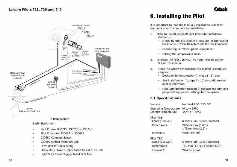
6.6.6.6.6. Installing the PilotInstalling the PilotInstalling the PilotInstalling the PilotInstalling the Pilot
It is important to read the Manual / Installation Leaflet foreach unit prior to commencing installation.
1. Refer to the 930609/619 Pilot Computer InstallationGuide for:• A step by step installation procedure for connecting
the Pilot 715/730/740 system into the Pilot Computer.
• Connecting Cetrek peripheral equipment.
• Setting the Jumpers and Links.
2. To install the Pilot 715/730/740 itself, refer to section6.2 of this manual.
3. Once the system’s mechanical installation is complete,carry out:• Dockside Settings (section 7, steps 1 - 6), and
• Sea Trials (section 7, steps 7 - 10) to configure thepilot to the vessel.
• Pilot Configuration (section 8) explains the Pilot andperipheral equipment settings for the system.
6.1 Specifications
Voltage: Nominal 12V / 24V DCOperating Temperature: 0º to +55ºCStorage Temperature: -20º to +70ºC
Pilot 715 Cable (510545): 6 way x 6m (19.5’) Screened. Dimensions: 220mm max (8.65”)
x 75mm max (2.9”) Enclosure: Weatherproof
Pilot 730 Cable (510529): 6 way x 6m (19.5’) Screened Dimensions: 110 mm (4.3”) x 110 mm (4.3”) Enclosure: Weatherproof.
Basic Equipment
• Pilot Control 930715, 930730 or 930740• Pilot Computer 930609 or 930619• 930580 Compass Sensor• 930809 Rudder Feedback Unit• Drive Unit for the steering• Heavy Duty Power Supply, fused to suit drive unit• Light Duty Power Supply, fused at 5 Amp
A Basic System

Leisure Pilots 715, 730 and 740
3332
Pilot 730
A Trunnion Mounting kit is available, part number 930293.
To bulkhead mount: Use the template to cut the holes in thebulkhead for the cable and 4 studs.
Pass the cable out through the bulkhead and connect it tothe rear of the Pilot 730. Screw the M4 studs into the rearcase. Place the pilot in position, then secure it to thebulkhead with the thumbnuts supplied.
Ideally, if the rear of the 730 is going into an enclosed area,that area should be adequately ventilated so that the rearsees the same ambient temperature as the front.
A 15 metre (49ft) cable is available, part nº 510548.
Allow adequate clearance for cable connections toensure cables are not unduly stressed and that thereis sufficient length of cable to remove the unit forservice purposes.
Not toScale
Pilot 740 Cable (510529): 6 way x 6m (19.5’) Screened Dimensions: 110 mm (4.3”) x 200 mm (7.8”) Enclosure: Weatherproof.
6.2 Mounting the Autopilot Control
For the sake of safety, there must be an autopilot controlwithin reach of the Helmsman AT ALL TIMES, to enable quickdisengagement of the Pilot.
Pilot 715
The Pilot 715 connects to the Bulkhead Socket. Thebulkhead socket and its cable connect to the Pilot Computer.The Socket requires a 25 mm (1.0”) diameter hole formounting.
A 6 metre (19.5ft) extension cable is available, part nº510499.
Extra socket positions can be installed, part nº 930027
Allow adequate clearance for cable connections toensure cables are not unduly stressed.
Observesocket and
plug matingalignment

Leisure Pilots 715, 730 and 740
3534
BulkheadConnector
Remove theplug fromthe firstcable.
Then connectthe wires ofboth units intothe plug of thesecond cable.The wires arethe samecolours.
Insert the plug into PL10.
6.3 Connecting the Pilot Control
Route the cable to the Pilot Computer. If the cable needs topass through a bulkhead, note the wire colours in theconnector, then remove it temporarily.
Incorrect wiring (e.g. reverse polarity) can causeirreparable damage to some equipment and is notcovered by Cetrek warranty.
Insert the connector into the Pilot Computer (PL10). Connectthe cable screen securely to the fixing ‘tongue’ using the twocable ties provided.
When connecting two or more Leisure Pilots, the wires mustbe connected in parallel, into the same connector, thenplugged into PL10.
BlackOrangeYellow
RedViolet
Brown
PL10GNDTX dataTX LatchLDSS+RX dataTX clock
654321
Connect the cable screento the fixing ‘tongue’.
Pilot 740
A Trunnion Mounting kit is available, part number 930289.
To bulkhead mount: Use the template to cut the holes in thebulkhead for the cable and 4 studs.
Pass the cable out through the bulkhead and connect it tothe rear of the Pilot 740. Screw the M4 studs into the rearcase. Place the pilot in position, then secure it inside thebulkhead with the thumbnuts supplied.
A 15 metre (49ft) cable is available, part nº 510548.
Allow adequate clearance for cable connections toensure cables are not unduly stressed and that thereis sufficient length of cable to remove the unit forservice purposes.
Not to Scale
Leisure Pilots 715, 730 and 740
3736
Dockside SettingsDockside SettingsDockside SettingsDockside SettingsDockside Settings
Summary of steps:1 Powering up for the first time.2 Setting the Rudder Feedback type.3 Setting boat type.4 Rudder settings routine.5 Aligning the compass.6 Checking the settings.
7.1 Powering up for the first time
Ensure that all units are installed correctly, that the correctsize fuses or circuit breakers are fitted and that the ship’sbatteries are adequately charged. Check that all the systemconnections are correctly made and return the rudder to themidships position before the power is applied.
Switch the Pilot system supply ON (both Heavy Duty andLight Duty Supplies).
If the pilot starts to move the rudder, switch off atonce and re-check the connections.
Press the key. If all is correct the Pilot displays a startupsequence (fully explained on page 10) finishing with
HEAD *** a heading display, which may not be accurate at this stage.
The Info line will display “ERROR” if a 730 or 740 and aProPilot are connected on the same system.
F A U L T 1 6 5 A 619 system with Gyro and no magnetic compass will give afault 165 (no compass) message when first powered up.Refer to section 8, page 48 and set the gyro settings, 8.24 to8.27, then restart the unit.
7.2 Setting the Rudder Feedback type.
The system comes from the factory set to Amplified for the930809 or 930819 Rudder feedback unit (RFU). If a 930837or other RFU is to be used, please refer to sections 8.0,page 48 and 8.12, page 55 if you need to change the signalamplification.
Step 2
Step 1
7.7.7.7.7. Dockside and Sea trial settingsDockside and Sea trial settingsDockside and Sea trial settingsDockside and Sea trial settingsDockside and Sea trial settings
Having completed the mechanical installation and wiring ofthe system, the next step is to configure the Pilot for thecharacteristics of the boat.
In order to use the pilot successfully, it is MANDATORY thatyou carry out the Boat Type and the Rudder Settings Routine.For the system to work correctly, both Dockside settings andSea trials, need to be completed fully.
The method below is used during Dockside settings and Seatrials.
While in standby, press and hold the and keysuntil “DOCKSIDE-[(]/SEATRIAL-[)]” isdisplayed.
Press the key to select the Dockside settings menu.
Press the key to select the Sea Trial settings menu.
Using the settings menus
The settings use self prompting, scrolling messages, givingdetails on how to change the setting or to skip to the nextoption:
SET BOAT TYPE/TO CHANGE-[)]/SKIP-[MODE]
The setting To change the setting To skip to the next press this key. setting, press this key
Do not engage Auto mode until the Dockside Settings havebeen completed.
To exit, at any time, press and hold the and keys.
To save any changed settings, turn the Pilot OFF by pressingand holding the key.
There are two summary cards supplied for these settings. Itmay be more convenient to use them after having read thisUser’s Guide.

Leisure Pilots 715, 730 and 740
3938
7.4 Rudder settings routine
Press the key, the display shows “RUDDERS E T T I N G S - [ ) ] / S K I P - [ M O D E ] ” .During the Rudder settings routine the rudder willbe moved under autopilot control. It is thereforeimportant to ensure the rudder and steering gearcan move safely from hardover to hardover withouthitting anything. Check that the steering movesfreely from lock to lock without undue stiffness andthat it can move to its full travel without the RudderFeedback arm fouling the steering.
The Rudder settings routine will set:-
• Rudder Phasing sets the rudder signal polarity so thatthe Pilot displays the correct direction of ruddermovement.
• Motor Phasing sets the correct direction of ruddermovement when commanded by the autopilot.
• Rudder Limits sets the maximum rudder movement,either side of midships, useable under autopilot control.
• Center Rudder sets the rudders midships position.
Press the key to start the Rudder settings routine.
First the Pilot scrolls the message “CENTER THERUDDER-[)]. Position the rudder at midships byviewing the actual rudder, then press the key.
The display will now scroll “RUDDER TOSTARBOARD END STOP-[)]”. Turn the helm tostarboard, to a position just before the mechanical end stopand with it held in this position press the key again.
A default value of 30º appears in the Heading Display andthe Information line scrolls “ENTER THIS RUDDERANGLE -[()]/SKIP-[MODE]“. Using theRudder Angle Template on page 67 estimate the currentangle of the vessel’s rudder just before the mechanical end
stop. Use the and keys to alter the default value tothe estimated angle. Press the key to enter thisinformation.
With the amplification correct, set the rudder to midships, ifthe Rudder Position display is 5 degrees or less, it will becorrected during the rudder settings routine. If over 5degrees, mechanically re-adjust the Rudder feedback unit(refer to its Installation Instructions).
Depending on how the Rudder Feedback Unit is mounted,the direction of the pilot’s rudder information may bereversed, this will be automatically corrected later.
7.3 Setting the Boat Type.
With the Pilot in Standby, press and hold the and keys until “DOCKSIDE-[(]/SEATRIAL-[)]” isdisplayed. Press the key to select the Dockside settingsmenu, the display scrolls the message “SET BOATTYPE/TO CHANGE-[)]/SKIP-[MODE]”.
In the Autopilot’s memory there are 4 boat types to choosefrom. Press the key to display the current Boat Type andthen press the key repeatedly to scroll through the boattypes, the setting left displayed will be the one used.
P L A N I N G PLANING hull (high speed power boat, 20+ knots)
S A I L B O A T SAILING vessel
D I S P L A C E DISPLACEMENT hull (up to 10 knots)
S E M I D I S P SEMI-DISPLACEMENT hull (10 to 20 knots)
Setting the Boat type to “SAILBOAT” enables the extrafacilities of Wind course control and its Tack function.
The Boat type selection restricts pilot settings as below:
Setting Response TrimPlaning 2 max 10 maxSailboat 20 max 20 maxDisplacement 20 max 10 maxSemi-displacement 5 max 10 max
Step 3
Step 4
Leisure Pilots 715, 730 and 740
4140
Press the key, “DOCKSIDE SETTINGSCOMPLETE [MODE]” will be displayed.
Press the key to exit the Dockside Settings menu.
Save the settings by holding down the key to turn thePilot OFF.
The Dockside settings are now complete.
7.6 Checking the settings
Press the key to turn the pilot back on.
Check that there are no bars present in the Rudder PositionIndicator when the rudder is in the midships position.
Turn the helm to Starboard until the rudder position scaleflashes. Check that the rudder has not quite reached themechanical limit of rudder movement.
Repeat for Port helm.
Re-centre the rudder. Switch the Pilot into Auto mode, bypressing the key. Very little or no rudder movementshould occur.
If the rudder drives continuously to one side, switchoff the power at the breaker at once. Check themechanical and electrical installation. There is aTroubleshooting Guide in the 930609/619Installation Guide which may help.
If the rudder continuously ‘hunts’ about midships, turn thePilot off and remove as much freeplay as possible from thesteering and Rudder feedback unit linkage. This also occurson Power Steering systems particularly if the steering isplumbed with flexible hose. If that does not stop it, increasethe Rudder Deadband setting, see section 8.9, page 54.
With the pilot in Auto mode, check that when you press andhold the key, the motor drives the rudder so that itsclose too but doesn’t touch the Starboard end stop. Checkthat the rudder display segments flash. The rudder shouldcentre when the key is released.
Step 6
The display scrolls “RUDDER TO PORT ENDSTOP-[)]”. Turn the helm to port, to a position justbefore the mechanical end stop and with it held in this
position, press the key again.
To prevent possible damage to your steering gear; ifthe Port and Starboard positions that you selectwere different angles the Pilot will set both RudderLimits to the smaller angle.
Now the Pilot asks you to “CENTER THE RUDDER-[)]”, centre the rudder again by viewing the actual rudder
and with it held in this position, press the key.
The display scrolls “NOW PRESS AUTO-[AUTO]”.Ensure the rudder is free to move, press the key, whichengages the motor and drives the rudder from hard over tohard over four times:
H-OVER 1 from the centre rudder position to a Rudder Limit
H-OVER 2 then across to the other Rudder Limit
H-OVER 3 the rudder is returned to first Rudder Limit
C E N T E R I N G and finally the rudder is centred again
”RUDDER IS NOW SET-[MODE]” is displayedto confirm that the Rudder Phasing, Motor Phasing, RudderLimits and Center Rudder settings have all been completedsuccessfully.
7.5 Align Compass
Not all compass’ support this feature. The 930580 and930687 do. For other compass’ see the documentation thatcomes with them.
Press the key, the display will show “ALIGNC O M P A S S - [ ( ) ] / S K I P - [ M O D E ] ” .
Using the and keys or Course control knob, set theheading display of the LCD to the vessel's approximateheading (this is set more accurately during the Sea Trials).
Step 5

Leisure Pilots 715, 730 and 740
4342
Press and hold the key, and repeat for Port rudder.
Hardover times can now be checked. Refer to sections8.6 Motor speed and 8.7 Motor ramp, to set DC reversingmotors.
Press the key to return to Standby mode.
Save any changed settings by holding down the key toturn the Pilot OFF.
You are now ready to start the Sea Trials.
Sea Trials Sea Trials Sea Trials Sea Trials Sea Trials
The next stage of installation is to set-up the Pilot at sea.
It is essential that your compass is properlycorrected.
Summary of Steps7 Automatic deviation correction of Cetrek compass’.8 Compass alignment for Cetrek compass’.9 Center the rudder
10 Final Sea trial and fine tuning
Steps 7 & 8 below correct the Cetrek compass’ 580 and 687.For other compass’ or Gyros, follow the documentation thatcomes with them then carry out steps 9 and 10.
To access the Sea Trials menu, with the pilot in standby, pressand hold the and keys simultaneously, then pressthe key.
Press the key to step through the settings.To exit, at any time, press and hold the and keys.To save any change settings, press and hold the keywhich also turns the Pilot off.
7.7 Automatic Compass DeviationCorrection for 930580 and 930687 compass’.
The 930580 and 930687 compass have facilities toautomatically measure and compensate for the majority ofcompass deviation found on board a vessel. The compasssensor must be mounted clear of strong magnetic fields,caused by heavy duty cables, motors, speakers etc.
Before continuing, ensure you have a method of obtainingan accurate heading, i.e. GPS, transits or a correctedmagnetic compass.
This must be performed in a calm sea, away fromlarge iron structures.It is dangerous to carry out these trials in restrictedor busy waters.
Step 7

Leisure Pilots 715, 730 and 740
4544
Step 8
The Pilot must have been turned off before the start of everydeviation correction run.
7.8 Compass alignment (Cetrek compass’)
Having completed the Automatic deviation correctionprocedure the compass must be ‘electronically’ aligned withthe vessel’s bow.
Press the key “ALIGN COMPASS-[)]/SKIP-[MODE]” is displayed. Hold the vessel on asteady heading. The compass heading is displayed. Using the
or keys, or the Course control knob, change thevalue until it is the same as the vessel’s true heading. Whencorrect, press the key.
Checking the compass settings
Comparison checks against known headings should becarried out to verify the accuracy of the compass.
Turn the vessel again through a full 360º with the Pilot inStandby mode. The live heading is displayed in largernumbers in the Heading display, note the amount of error atthe eight Cardinal and Intercardinal points. The error shouldnow have reduced to less than +/- 3º at each point.
If this accuracy cannot be achieved, the compass willprobably need to be moved and corrected again.
619 Only. If two compass’ have been fitted on a 619 system, bothwill need selecting, then calibrating and aligning, seperately.
Turn the vessel through a full 360º with the Pilot in Standbymode and note the amount of error at the eight Cardinal andIntercardinal points.
The deviation correction requires the vessel to turnCLOCKWISE approximately 2½ times, in a smooth turn.
Turn the system on. In Standby mode, press and hold the and keys until
“DOCKSIDE-[(]/SEATRIAL-[)]” isdisplayed. Press the key to select the Sea Trial settings.
The Pilot will now display“COMPASS CORRECTION-[)]/SKIP-[MODE]”.
Press the key“COMPASS UNCORRECTED CALIBRATENOW-[)]/SKIP-[MODE]” is displayed.
Begin your turn, then press the key to start thesequence running, the Pilot displays “TURNBOAT”.....
The display then shows “KEEP TURNING”.
After approximately 2½ turns the display shows“COMPASS CORRECTED-CALIBRATE NOW-[)]/SKIP[MODE]”, the automatic deviationcorrection routine has been completed.
If the pilot displays “COMPASS CORRECTED-CALIBRATE NOW-[)]/SKIP[MODE]” itmeans that the autopilot already has correction valuesstored. Press the key to erase previous information and“COMPASS UNCORRECTED-CALIBRATENOW-[)]/SKIP-[MODE]” is displayed.
If “ERROR 7” or “8” is displayed, the compass has astrong magnetic field too close to it. Remove the source orrelocate the compass to a more suitable position.
To abort the routine, press the and keys together.The display returns to “COMPASS UNCORRECTED-CALIBRATE NOW-[)]/SKIP-[MODE]”.Turn the Pilot off by pressing the key.

Leisure Pilots 715, 730 and 740
4746
Check and readjust the motor speed (section 8.6) and motorramp (section 8.7) if necessary.
Set sensible Dodge limits, see section 8.11 on page 54.
619 only, set Pilot B and C values, although they may need towait for different sea states to fully check them.
The Pilot installation is now complete.
Save any changed settings by holding down the key toturn the Pilot OFF.
7.9 Center Rudder
Press the key until “CENTER RUDDER-[)]/SKIP-MODE]” is displayed.
This routine will set the electronic center rudder positionmore accurately than that set in the dockside settings.
Steer the vessel on a straight heading, at normal cruisingspeed (ensure that there is no cross wind or similar requiringStanding Helm). Press the key to set the current rudderposition as the new midships position.
The message “CENTER RUDDER-[)]/SKIP-MODE]” is displayed to allow the setting to be done againif needed.If the position is correct, press the key and the Pilot willexit the Sea trial settings mode.
7.10 Final Sea Trial and Fine Tuning
Steer the vessel in a straight line at normal cruising speedand press the key.The vessel should now hold a steady course.
If the vessel does not hold a steady course, change the SeaState adjustment Rudder Ratio to set the pilot for optimumperformance, as you would on any voyage (see section 5,page 25).
If the vessel drifts off course to one side, increase the rudderratio setting by one.
If the vessel oscillates from side to side, decrease the rudderratio setting by one.
Change it one step at a time.
Press the key repeatedly until “RuddeR” is displayedfor Rudder Ratio and change the setting by using the
or keys.
Press the key to regain Manual Control.
Step 10
Step 9

Leisure Pilots 715, 730 and 740
4948
Press the key, “RESP ” is displayed. Change thesetting by using the or keys.
The range of settings is:Adaptive (A0 to A5) then from 1(Very responsive) to 20 (Least responsive).Planing boat types are limited to a maximum setting of 2,Semi-displacement boat types to a maximum of 5,Sailboat and Displacement boat types to 20.
8.3 Counter Rudder
C-rUD 8 To prevent the vessel from overshooting at the end of a largecourse change, the amount of applied rudder is reduced asthe vessel approaches the new heading.If the vessel is turning fast, the applied rudder needs to bereduced earlier than if the vessel was turning slowly.
This setting balances the rate that the vessel is turningagainst the rate at which the reduction of applied rudderoccurs.
If this is set too high the vessel will not settle on to the newheading quickly enough.
If the Counter Rudder is set too low the vessel will overshootand the pilot will have to correct with opposite helmaccordingly, possibly causing the vessel to oscillate from sideto side, before settling to the new heading.
Press the key "C-RUD " is displayed.Change the setting by using the or keys.
The range is from 0 (No Counter Rudder) to 20 (MaximumCounter Rudder).
This setting can be turned on, then viewed and adjusted in theInfo list.
8. Pilot configuration reference
This section contains details of the Pilot configurationsettings. They rarely need adjustment, but might be neededto fine tune the Pilot for an unusual vessel, or for settingperipheral equipment options.
To access the Pilot Configuration menu, with the Pilot instandby, press and hold the key until“CHANGE SETTING-[()]/FORWARD-[MODE]/BACKWARD-[INFO]” is displayed.
Pressing the key steps forwards through the list of settings.Pressing the key steps back through the list of settings.
Pressing and holding the key now exits the menu, thenre-enters it at the last viewed setting.
To save changed settings, turn the Pilot OFF by pressing andholding the key.
8.1 Rudder ratio
RUDDER 5 The Rudder ratio setting is usually altered from theinformation display, see section 5, page 25. This is analternative place to change the value.Press the key, "RUDDER" is displayed.Change the setting by using the or keys.
The range is from 0 (Minimum movement) to 20 (Maximummovement).
8.2 Response
RESP A 2 The Response setting is usually set to Adaptive but can beturned on and altered from the Information display, see‘manual control’, section 5, page 26. This is an alternativeplace to change the value.Response sets the amount that the vessel is permitted tomove off course before rudder is applied to bring it backonto its set heading.

Leisure Pilots 715, 730 and 740
5150
8.6 Motor Speed (DC reversing motors only)
MOTSP100 Motor Speed limits the drive motor speed to give ahard-over to hard-over time suitable for the vessel. This isespecially useful if the vessel has a high steering inertia.
PWM (Pulse Width Modulation) is the method used tocontrol the speed of the motor.
The Motor Speed setting starts at 100%, which is themaximum motor speed the drive unit can provide. Press the
key to reduce the speed (increasing the Hard-overtime), to achieve the Hard-over to Hard-over time calculatedfor your vessel.Hard-over time is double at 50% power.
As a guide, the Hard-over to Hard-over time should beapproximately:
Planing vessel's 8 - 12 secondsSemi-Displacement vessel's 11 - 16 secondsDisplacement and Sailing vessel's 15 - 18 seconds
Press the key, "MOTSP" or “PWM 0FF” isdisplayed. Change the setting by using the or keys.
The range is from PWM OFF, then 100% to 50% inincrements of 5%.
The default is 100%.
PWM OFF There are a few conditions when PWM is a disadvantage,such as running down wind with a large following sea. Toswitch PWM off, press the key until “PWM 0FF” isdisplayed.
PWM is automatically turned off when J3 in the PilotComputer is set for spool valve operation.
8.4 Turn Rate (619 Pilot Computers only)
TURNR 16 This sets the minimum radius of turn that is allowed whenunder Pilot control. When set to 0 (off) the rate of turn isnot limited and small radius turns are allowed.The range is from 0 (off), then 1 (large radius turns only) to20 (small radius turns allowed).
This setting can be turned on, then viewed and adjusted inthe Info list.
8.5 Trim
TRIM 4 Normally, if the rudder is amidships the vessel will travel in astraight line. Sometimes something will cause the vessel todrag to one side, for example the wind, towing something orcurrent. To counteract this, a few degrees of rudder will beapplied, this is termed Trim or Standing Helm.This setting adjusts the rate at which that standing helm isapplied.
The higher the setting, the faster the standing helm isapplied. This should be set so that the Pilot will trim thevessel within 60 seconds. On single screwed vessel's or sailingyachts it is only possible to check the Trim setting while usingthe craft when, for example, the prevailing conditions causethe vessel to steer with offset rudder. The correct Trimadjustment setting for these types of vessel is therefore bestfound by experience.
To check the Trim adjustment with twin engine vessel's, runthe boat under Pilot command with both engines running,then close down one engine. The vessel will initially go offcourse but should return to course in less than 60 seconds. Ifthe vessel takes a longer period of time to return to coursethen increase the value set for Trim.
Press the key, "TRIM" is displayed.Change the setting by using the or keys.
The range is from 0 (No Trim) to 10 (Maximum Trim)although if the Boat type is set to SAILBOAT, the maximum isincreased to 20.
This setting can be turned on, then viewed and adjusted inthe Info list.
Leisure Pilots 715, 730 and 740
5352
8.8 Transition Speed (for Rudder Ratio)
NO TRSPD The Transition Speed setting indicates to the Pilot when toincrease rudder ratio, to give you greater rudder movementfor manoeuvring at slower speeds. As your speed changes,the software creates a gradual adjustment of Rudder ratio,instead of using the fixed Rudder ratio value. This obviouslyrequires NMEA speed information to be available to the PilotComputer.
This setting is most beneficial for planing vessel's which needincreasing rudder movement to maintain steering controlwhen not on the plane.
Establish at what point, in knots, your vessel is comfortablyon the plane. Enter the Pilot Configuration menu and usethe key to increase the Transition Speed setting to thisvalue.
Above this value the Pilot will use the Rudder ratio setting.Below it, the amount of Rudder ratio is gradually increased,up to double, giving more control at slower speeds.
Press the key, "NO TRSPD" is displayed. Change thesetting by using the or keys.
The range is from NO TRSPD (no transition speed) to 50knots in increments of 1 knot.
If there is no speed data available, set this to NO TRSPD.
The Pilot can use speed data from an NMEA 0183 speed orvelocity message, refer to the 930609/619 Pilot ComputerInstallation Guide for more details.
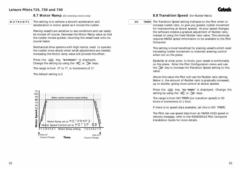
8.7 Motor Ramp (DC reversing motors only)
M O T R A M P 2 This setting is to achieve a smooth acceleration anddeceleration in motor speed as it moves the rudder .
Planing vessel's are sensitive to sea conditions and can easilybe moved off course. Decrease the Motor Ramp value so thatthe rudder moves quicker, returning the vessel back onto itscourse faster.
Mechanical drive systems with high inertia, need to operatethe rudder more slowly when small adjustments are needed,increasing the Motor ramp value will provide this effect.
Press the key, "MOTRAMP-" is displayed.Change the setting by using the or keys.
The range is from 0º to 7º, in increments of 1º.
The default setting is 2.

Leisure Pilots 715, 730 and 740
5554
8.12 Amplified Rudder Feedback Unit
AMPFD FB This setting is the software equivalent of moving J1 in thePilot computer. Some Rudder feedback units require thesignal amplifier to be turned off. Provided the jumper J1 inthe Pilot computer is in the factory default position(amplified), this setting turns the amplifier off or back on.
Set to Amplified for set to Non-amplified for930809 930837930819 Linears with integral RFU
Press the key, the current setting is displayed.Change the setting by using the or keys.
The choice is “AMPFD FB” amplifier on (factory default)or “NOAMP FB” No amplification.
8.13 Rudder Gauge Type
C E T R E K This setting is not used yet.
8.14 Wind Gain
Wind Gain is only used when “SAILBOAT” is selected asthe Boat Type.
WNDGN 1 This sets the gain of the signal from the NMEA Windvane. Ifthe vessel does not respond to wind shifts fast enough,increase the setting.Press the key, "WNDGN" is displayed.Change the setting by using the or keys.
The range is from 0 (no Wind Gain) to 10 (maximum WindGain).
8.9 Rudder Deadband
RDBND 3 Some steering systems have slack in them, owing to wear orsystem design, which gives a few uncontrolled degrees ofrudder movement. Hydraulic drive and power steeringsystems often have some overshoot.
To stop the Pilot trying to correct these small movementswhich it can never do, the rudder deadband setting allows asmall course error movement without the pilot applyingrudder.
Press the key, “RDBND” is displayed. Use the or keys to set this to the minimum value that avoids
hunting of the rudder. The range is from 0 (0º) to 20 (2º).
Too much slack in the steering system will affectPilot performance.
8.10 Rudder Limits
RUDLIM 7 This allows adjustments to the maximum rudder movement,either side of midships, obtainable under autopilot control.The Dockside Settings automatically calculated this value,however Rudder Limits allows manual override.Press the key, "RUDLIM" is displayed. Change thesetting by using the or keys.
The range is from 4 (16º) to 10 (40º).
Ensure the limit setting does not allow the rudder totouch its mechanical end stops.
8.11 Dodge Limits
D G E L I M 1 0 This limits the maximum rudder movement, either side ofmidships, that the dodge function can use. It should be setso that the vessel will not execute a dangerous turn at fullspeed.Press the key, "DGELIM" is displayed. Change thesetting by using the or keys.
The range is from 1 (4º) to 10 (40º). It cannot be set greaterthan the Rudder Limit.

Leisure Pilots 715, 730 and 740
5756
8.16 Off Course Alarm (619 0nly)
An Off Course Alarm can be turned on. It can be set from 1ºto 20º in 1º steps.
Oca off As soon as the vessel has been Off Course by the set amountfor a period of 30 seconds the alarm will be triggered.
The alarm will be triggered instantly if the vessel becomes offcourse by more than twice the set amount.
Once the vessel is back on course the alarm will cancel. Itcannot be manually cancelled.
The range is from OFF, then 1 (1º) to 20 (20º).The default is OFF.
Press the key, "OCA OFF" is displayed. Change thesetting by using the or keys.
8.17 External Alarm (619 0nly)
XALM ON This allows any external alarm system connected to User Port2 in the 930619 Pilot Computer to be turned on or off.Press the key until "XALM OFF" is displayed. Turnthe alarm on or off by using the or keys.The default is on.
8.18 Power Steer Gain
PSTEER 5 This adjusts the sensitivity of the steering when it iscontrolled by a remote Cetrek Proportional steer.Press the key, "PSTEER" is displayed. Change thesetting by using the or keys.
The range is from 1 (least sensitive) to 10 (most sensitive).The default is 5.
8.15 Tack Angle
Tack Angle is only used when “SAILBOAT” is selected asthe Boat Type.
T A C K A 1 0 0 This is the angle through which the vessel will tack when aPort or Starboard Tack is initiated under Compass control.The tack function uses the compass heading and subtracts oradds the tack angle to create the new course to Port orStarboard, respectively. Manually calculate the Tack Angle inthe normal way and enter it here.
Tack Angle
Press the key, "TACKA " is displayed. Change thesetting by using the or keys.
The range is from 60º to 110º in increments of 10º.

Leisure Pilots 715, 730 and 740
5958
8.20 Waypoint Sequence
When following a route, prepared on a navigator or plotter,there are two options: the Pilot can follow the whole routeautomatically or to require manual acceptance of a changeof course.
AUTO WPT When Automatic Waypoint Sequence is selected, the Pilot onreaching a waypoint will flash the bearing to next waypoint,for 7 seconds, but turn onto it automatically after the first 2seconds.
MAN WPT When Manual Waypoint Acceptance is selected, the Pilot, onreaching a waypoint, will scroll the message “NEW WPTPRESS AUTO” for 10 seconds. The vessel will not turn ontothe new course unless the key is pressed.
If the key has NOT been pressed, after 7seconds the Pilot will switch to Compass controland continue on its present heading until newinstructions are received.
In the Pilot Configuration Menu, press the key until"AUTO WPT" or “MAN WPT” is displayed. Change thesetting by using the or keys.
8.21 Navigator Name
N A V 1 N A M E Change the Navigator Name to reflect the type of navigatorconnected to NMEA 1: "NAV", "DECCA", "LORAN", "GPS" or"PLOT".Additional ports, NMEA 2 and NMEA 3 are available with a930619 Pilot Computer. Change the NAV2 and NAV3NAME,in the same manner, if other navigators are fitted.
Change the setting by using the or keys.
8.19 Navigator Gain
NAVGN 5 If your Pilot is working with a Navigator, adjustment ofNavigator Gain will be available. The speed of the vesselaffects the Navigator Gain, high speed requires lessNavigator Gain and slow speed requires higher NavigatorGain
Set the navigator’s output data to minimum damping (1second intervals) and set the Navigator Gain to 5 (this issuitable for most applications).
If this is set too high the pilot will trim the vessel’s course toomuch causing the vessel to oversteer either side of thedesired track. If the Navigator Gain is set too low the vesselis pushed off track, the pilot will not bring the vessel to thedesired track “XTE 000”.
Press the key, “NAVGN” is displayed.
The range is from 0 (No Gain) to 9 (Maximum Gain).The default setting is 5.
Navigator Gain
Leisure Pilots 715, 730 and 740
6160
8.24 Gyro Type(619 systems only, when Compass Type 8.27 is ‘Gyro’)
G Y R O S T E P Selects between Stepper and HDT gyro types.Change the setting by using the or keys.
If this is changed incorrectly an alarm message shows. Pressthe key to supress the alarm and let the setting becorrected.
If an HDT gyro is being used, when the info line displays theheading , the character after ‘GYRO’ blinks its top bar as areminder.
8.25 Gyro Cal(619 systems only, when Compass Type 8.27 is ‘Gyro’ andGyro Type 8.24 is Stepper)
GYRO CAL This calibration aligns the Gyro with the vessels heading.Press the and keys simultaneously. The heading willflash. Use the and keys or rotate the Course controlknob until the LCD displays the ships heading.Press the and keys simultaneously to accept thesetting.If the system is set to startup in Gyro Stepper mode,calibration will be displayed whenever the system is poweredup. Set the heading as above , then the Pilot will switch tonormal mode.
8.26 Gyro ratio(619 systems only, when Compass Type 8.27 is ‘Gyro’ andGyro Type 8.24 is Stepper)
G Y R A T 3 6 0 When first installing the gyro stepper it will be necessary totell the pilot the gyro rate. It can be 90, 180 or 360.Press the and keys simultaneously to change thesetting.
8.27 Gyro or Magnetic compass (619 systems only)
M A G N E T I C This allows switching between a Magnetic and a Gyrocompass.Change by pressing the and keys simultaneously.
If this is changed incorrectly an alarm message shows. Pressthe key to supress the alarm and let the setting becorrected.
8.22 Compass Damping (580 compass 0nly)
AUTO CD The Pilot will automatically calculate a suitable dampingsetting for the compass display to correspond with seaconditions, using the Automatic Compass Damping routine.
The normal setting is Automatic Compass Damping, this mayonly need to be changed if the compass has been mountedhigh above the waterline.
Press the key, "AUTO CD" or “CDAMP” isdisplayed. Change the setting by using the or keys.
The range of settings is: Automatic Compass Damping; thenfrom 1 minimum to 10 maximum damping.The default is Automatic.
8.23 Compass source(619 systems only, when Compass Type 8.27 is ‘Magnetic’)
C O M P A U T O This allows selection between two magnetic compass’. Theoptions are ‘AUTO’, ‘INTERNAL’ or ‘ EXTERNAL’.When “AUTO” is selected, at power up, the 619 will look fora 580, if it cannot find one it will look for a HDM or CetrekData message on PL12 and use that.
‘INTERNAL’ forces the 619 to use the 580 compass.
‘EXTERNAL’ forces the use of the compass connected to PL12.
Press the key, "COMPAUTO" , “COMP INT” or“COMP EXT” is displayed.Change the setting by using the or keys.
If this is changed incorrectly an alarm message shows. Pressthe key to supress the alarm and let the setting becorrected.
If an external compass is being used, when the info linedisplays the heading , the character after ‘HEAD’ blinks itstop bar as a reminder.

Leisure Pilots 715, 730 and 740
6362
8.30 Pilot Configuration menu summaryFrom standby, press and hold key to enter or exit this menu.
Key Display Function See Section
R U D D E R Rudder Ratio (0-20 ) .............................................. 5.1 and 8.1
R E S P Response (A1-5, then 1-2, 5 or 20) ......................... 5.2 and 8.2
C - R U D Counter Rudder (0-20) ....................................................... 8.3
TURNR * Turn Rate (0-20) ................................................................... 8.4
T R I M Trim (0-10 but Sailboat 0-20) ............................................. 8.5
M O T S P Motor Speed Control, or PWM Off ..................................... 8.6
MOT RAMP Motor Ramp Control(0-7) ................................................... 8.7
T R S P D Transition Speed, 0 to 50 knots .......................................... 8.8
R D B N D Rudder Deadband (0-20) .................................................... 8.9
R U D L I M Rudder Limits (4-10) ......................................................... 8.10
D G E L I M Dodge limit (1-10) ............................................................ 8.11
A M P F D Rudder Feedback amplifier (On/Off) ................................. 8.12
C E T R E K Spare setting, not used. ................................................... 8.13
W N D G N Wind Gain.(0-10) .............................................................. 8.14
TACK ANG Tack Angle.(60-110) .......................................................... 8.15
OCA * Off Course Alarm.(OFF, 1º-20º) ......................................... 8.16
XALM * External Alarm. (ON or OFF) ............................................. 8.17
P S T E E R Power Steer Gain (1-10) ................................................... 8.18
N A V G N Navigator Gain (0-9) ......................................................... 8.19
AUTO WPT Waypoint Sequence (Auto or Manual) ............................ 8.20
NAV NAME Navigator Name ............................................................... 8.21
AUTO CD Compass Damping, (Auto or 0-5) ..................................... 8.22
COMPAUTO * Magnetic Compass Source (Auto,Int,Ext) ......................... 8.23
STEPPER * Gyro Type (Stepper or HDT) .............................................. 8.24
GYRO CAL * Gyro Calibration (set heading) ......................................... 8.25
GYRORATE * Gyro Ratio (90, 180 or 360) .............................................. 8.26
MAGNETIC * Compass Selector (Magnetic or Gyro) .............................. 8.27
R E S T O R E Restore defaults (not Rudder & Compass) ........................ 8.28
R E S E T A L L Clear Rudder & Compass , restore all defaults. ................. 8.29
(*= not always seen, dependant on Pilot computer and configuration)
�
�
�
�
Press and hold the key to exit the Pilot Configurationmenu.
Save any changed settings by turning the Pilot OFF bypressing and holding the key.
It is advisable to record the optimised settings, incase they are accidentally changed at any time.
Be cautious about using these next twosettings.
8.28 Restore
r E S t o r e When this message is displayed, pressing the and keys simultaneously will return the default
values to all settings ( including boat type to Planing) apartfrom the Rudder Settings and Compass Calibration andAlignment values.The display will flash once when the values have been reset.Reset the boat type, unless it is a Planing hull, as described insection 7, step 3, page 38.
8.29 Reset All
R E S E T A L L When this message is displayed, pressing the and keys simultaneously will clear all values. It
will also reset the default values to all other settings.The pilot will switch off once the reset has been done.
Leisure Pilots 715, 730 and 740
6564
10. System F10. System F10. System F10. System F10. System Faultsaultsaultsaultsaults
The System faults are identified by numbers as indicatedbelow. A full list of system faults can be found in the PilotComputer Installation Guide.
For safety reasons, some faults will result in theautopilot automatically switching to Manual mode.
002 NOVRAM CHECKSUM ERROR• This fault may indicate that the Autopilot’s storedparameters are no longer valid, these should be checkedbefore further use. It may appear immediately after asoftware update. If so, switch the unit off at the Pilot Controlhead and back on again to clear it.
036 EXTERNAL COMPASS MESSAGE FAULT• The compass message has not been received correctly bythe Pilot Computer.If this occurs repeatedly then the compass should berepaired.
Warning messages 128 and above are accompaniedby a visual alarms, and the autopilot will switch tostandby (manual) mode.
130 STACK OVERFLOW• Indicates that the software has crashed. This may be due toexcessive electrical noise near the pilot computer. Removeany sources of electrical noise then power OFF and back ONagain to clear the fault. If the problem persists, consult yourlocal Cetrek dealer or distributor.
134 CONTROL HEAD ALARM.• Indicates that data from the Pilot Control connected toPL10 is not present. Check the cable and connections.
165 COMPASS TIMEOUT• The Pilot computer is not receiving heading informationfrom the compass/gyro. Check the supply and wiring.If a 580 sensor is connected, check PL8, pins 2, 3 and 4. Theirvoltage should be 2.5V ±1.5V, if they are not, the compass isfaulty.
9. System Messages9. System Messages9. System Messages9. System Messages9. System Messages
If your autopilot detects a problem with the system it willdisplay a warning on the LCD. For safety, a very seriousproblem will also turn the autopilot to Standby (manualsteering) mode. Here are the messages that we hope you willnever see, along with some explanations and some tips onwhat to do before you call your Cetrek dealer.
System AlarmsLOW BATTERY The battery voltage is low.
• Clear the alarm by pressing any key except the OFF key.Once cleared the alarm will not trigger again until theautopilot has been turned off and back on again. If thevoltage drops too low, autopilot operation may be impaired.Check the vessel’s charging system.
WIND ALARM The autopilot has “timed out” after not receiving expected WindInstrument Data.• Check the Data output from the Wind instrument.
NAVIGATORALARM
• The autopilot has received more Navigator Data than itexpected or
• The autopilot has “timed out” because it has not receivedexpected Navigator Data within a predetermined length oftime.
Make the following checks:
• That the Navigator is turned on.• That the Data output format from the Navigator is
NMEA 0183.• That NAV is selected correctly.• On the PCB inside the Pilot computer there are LED’s
beside each NAV port (PL11 in 609, PL11, 16 & 17 in 619).The LED for each port will flash if data is being received bythat port.
• Check the Navigator for bad reception or faultyequipment.
• Check the data output from the Navigator.

Leisure Pilots 715, 730 and 740
6766
176 RATE SENSOR ALARM• Indicates that the data signal from the optional Rate Gyrois no longer present (PL19 pin4 is at 5V). PL19 pin4 should beat a nominal 2.5V when data is present.
192 GYRO STEPPER ALARM• Indicates that the data signals from the Gyro stepper arefaulty, all high or all lowCheck LEDs on 930525 PCB.
198 RUDDER FEEDBACK FAULT• This may be caused by a fault in the Rudder Feedback Unit,wiring, excessive travel on the Rudder Feedback Arm or thelink J1 (or the software setting) is set incorrectly.Check that the Rudder Feedback Unit and its linkage has notbeen knocked or damaged.
200 MOTOR PHASING CHECK• This indicates that the rudder setting data is wrong. Repeatthe rudder setting routine detailed in section 7.4.
224 RUDDER DRIVE FAULT• The Pilot computer has sent a drive command to the driveunit but the Rudder Feedback Unit has not detected a changein the rudder position.
Check that the Rudder Feedback has not becomedisconnected from the Rudder Arm, also check that thesteering system, especially the motor, is operating the ruddergear correctly.
Ensure that the drive unit cables have not becomedisconnected or loose.
If You Need Assistance
If you do ever need to contact your Cetrek Dealer orDistributor, it would save time if you could make a note ofthe following details for them:
For each unit in the system:Model number:Serial number:Software version:
A description of the failure.
11. Rudder Angle T11. Rudder Angle T11. Rudder Angle T11. Rudder Angle T11. Rudder Angle Templateemplateemplateemplateemplate

Leisure Pilots 715, 730 and 740
6968
IndexIndexIndexIndexIndex
AAdaptive ........................................ 26Alarm ............................................. 64Alarm, audible ............................... 57Alarm, external .............................. 57Alarm, Off Course .......................... 57Align Compass ............................... 40'AMPFD FB' ..................................... 55Amplified RFU ................................ 55Apparent Wind Angle .................... 18Arrow Keys .................................... 12Audible alarm ................................ 57'AUTO CD' ....................................... 60Auto Mode ..................10, 11, 23, 59Auto Symbol .................................. 10Automatic Waypoint Following 23, 59Autopilot Control .................. 3, 7, 32
BBasic Equipment ........................ 3, 30Bearing to Next Waypoint .22, 23, 59blinking bar ................................... 17Boat Type .....................12, 13, 18, 38Bulkhead Socket ............................ 32
CCable ....................................... 31, 35
Screen ....................................... 35Calibrate, Compass ........................ 44Calibrate. Gyro ............................... 61'CDAMP ' ........................................ 60Center rudder ................................ 46Changing Course ........................... 19Clear all values ............................... 62Compass
Align ......................................... 45Deviation Correction ................. 43
Compass Control ..................... 17, 56
Compass Damping......................... 60Compass Sensor .................. 3, 30, 44Compass source ............................. 60Connections ................................... 35Counter Rudder ............................. 49Course Change ........................ 12, 13Course, Off alarm .......................... 57Course Over Ground ...................... 20Course Select Knob ........................ 13Cross Track Error ............................ 22Customising ................................... 14
DDefault settings ....................... 38, 68Depth Units ................................... 14Deviation Correction,Compass ....... 43Dimensions .................................... 31Displacement Vessel ...................... 38Dodge ............................................ 12Drag............................................... 50Drive Unit .................................. 3, 30
EEnd stop ........................................ 40Engage Navigator Control ............. 17Error, compass ............................... 44External Alarm ............................... 57
FFunction keys ................................... 7
GGybing ........................................... 19Gyro ............................................... 61Gyro Cal ......................................... 61Gyro ratio ...................................... 61Gyro Type ....................................... 61
12. Default settings12. Default settings12. Default settings12. Default settings12. Default settingsBoat type variations:609s use Pilot A settings.
Planing boat type Pilot A, B, CRudder Ratio 4, 6, 6Counter Rudder 1, 2, 2
Semi disp. boat type Pilot A, B, CRudder Ratio 7, 10, 10Counter Rudder 3, 4, 4
Disp. boat type Pilot A, B, CRudder Ratio 10, 12, 12Counter Rudder 4, 6, 6
Sailboat boat type Pilot A, B, CRudder Ratio 10, 12, 12Counter Rudder 4, 6, 6
INFO list 609 619Live Heading ON ONLighting ON ONPilot A, B, C (619 only) ONRudder Ratio ON ONResponse OFF OFFCounter Rudder OFF OFFTurn Rate (619 only) OFFTrim OFF OFFWPT Name ON ONXTE ON ONBearing ON ONDistance ON ONSpeed ON ONDepth ON ONWind angle ON ONWind speed ON ONSOG ON ONCOG ON ONWater Temperature ON ONBattery Voltage ON ONDig. Rudder Angle OFF OFF
Pilot SettingsBoat type PlaningRudder Ratio 4Response AdaptiveCounter Rudder 1Turn Rate (619 only) 20Trim 4Motor Speed Control 100%Motor Ramp 2Transition Speed no trspdRudder Deadband 3Rudder Limits (Set at Dockside settings)Dodge Limits 10Amplified RFU AMPFD FBRudder Gauge Type CETREKWind gain 1Tack Angle 100ºOff Course Alarm (619 only) OFFExternal alarm (619 only) ONPower Steer Gain 5Navigator Gain 5WPT Sequence AutoNavigator Name 1 NameNavigator Name 2 (619 only) NameNavigator Name 3 (619 only) NameCompass Damping AUTO CDCompass Type AUTOGyro Type (619 Gyro only) StepperGyro Cal (619 Stepper only) 00Gyro Ratio (619 stepper only) 360Magnetic or Gyro (619 only) MagneticRestore not relevantReset All not relevant

Leisure Pilots 715, 730 and 740
7170
HHard-over time......................... 42, 51Hardover time ................................ 51Heading ............................. 12, 24, 37Hunting ......................................... 54
IInformation display ....................... 13Information List ......................... 9, 13Installation Settings ....................... 37Installation Steps 1- 5 .................... 36
JJog Steer ........................................ 11Jumper J1 ...................................... 55
KKeyboard ......................................... 9
LLCD Display ...................................... 9Lighting ......................................... 16Low Battery ................................... 64
MManual Control ....................... 11, 17Manual Waypoint Acceptance ....... 59Menu ............................................. 36Motor Speed Control ..................... 51Motor Speed Reduction Angle ....... 52Mounting pilots ................. 32, 33, 34
NNavigator
Control ..................................... 20Course Over Ground ................. 20Selecting NMEA Input ............... 22
Navigator Alarm ............................ 24Navigator Gain .............................. 58Navigator Name ............................ 59'NEW WAYPOINT PRESS AUTO . 23, 59
NMEA0183 Messages ......................... 21Speed Message ......................... 25
NMEA sentences ............................ 15'NO TRSPD' .................................... 53'NOAMP FB' .................................... 55
OOFF .................................................. 9Off Course Alarm ........................... 57Operating Temperature .................. 31Oversteer ....................................... 25
PPilot A, B, C .................................... 16Pilot Computer .............. 3, 25, 30, 35Pilot Configuration .............. 9, 48, 63Planing Vessel ................................ 38Power Steer Gain ........................... 57Power Supply ................................. 30Pulse Width Modulation ................ 51PWM .............................................. 51
RRate Sensor .................................... 10Reset All ......................................... 62Response ................................. 25, 48Response,Adaptive ........................ 26Restore .......................................... 62Rudder
Center ....................................... 46Centering .................................. 55Deadband ................................. 54Ratio ................................... 25, 48
Rudder Angle Template .................. 39Rudder Feedback Unit .......... 3, 30, 38Rudder Limit .................................. 15Rudder Limits ........................... 40, 54Rudder Position Indicator .............. 15Rudder Ratio .................................. 46
Rudder Settings Routine ................ 39Motor Phasing .................... 39–40Rudder Limits ............................ 39Rudder Phasing ......................... 39Rudder Position Display ............ 37Rudder Set ................................ 40
SSafety ......................3, 13, 23, 32, 65Sailing Vessel ..................... 18, 38, 51Sea State Adjustments ................... 25Sea Trials ........................................ 43Self Test ......................................... 10Semi-Displacement Vessel .............. 38Skip ................................................ 36Software Version Number .............. 10Specifications................................. 31Speed
NMEA ....................................... 25Transition (Rudder Ratio) .......... 53
Spool Valve .................................... 10Standby Mode ............................... 10Standby Symbol ............................. 10Standing helm ............................... 50Switching Off ................................... 9Switching On ....................... 9, 10, 37System Faults ................................. 65System Messages ........................... 64
TTack
Angle ............................ 13, 17, 56Port ........................................... 17Starboard .................................. 17
Tack function ........................... 12, 13Target ............................................. 20Temperature ratings ....................... 31Top bar .................................... 60, 61Transition Speed (Rudder Ratio) ..... 53Trim ............................................... 50Turn radius ..................................... 50Turn Rate ....................................... 50
UUndersteer ..................................... 25
WWaypoint Identifier ........................ 22Waypoint Sequence ....................... 59Wind Alarm ................................... 64Wind Control ................................. 18Wind Gain ..................................... 55Windvane control .......................... 18